JLRTB02018 - 'Smart key not found' Message Displayed On Instrument Panel Cluster (IPC) and Intermittent Smart Key Operation
JLRTB02018 - 'Smart key not found' Message Displayed On Instrument Panel Cluster (IPC) and Intermittent Smart Key Operation
JLRTB02018
TECHNICAL BULLETIN
17 FEB 2020
![]()
© Jaguar Land Rover Limited
All rights reserved.
SECTION:
419-10
SUBJECT/CONCERN:
'Smart key not found' Message Displayed On Instrument Panel Cluster (IPC) and Intermittent Smart Key Operation
MARKETS:
ASIA PACIFIC; CHINA; EUROPE; JAPAN; KOREA; MENA; OVERSEAS
CONDITION SUMMARY:
SITUATION:
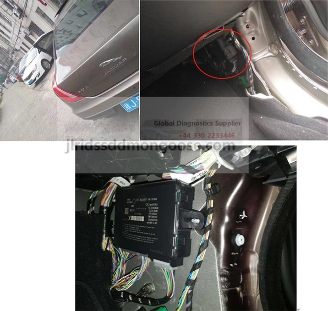
The 'Smart Key Not Found' warning message is displayed on the with possible intermittent smart key operation.
CAUSE:
Possible >span class="acronym">Radio Frequency (RF) coaxial cable concern or defective RF receiver. Suggested customer concern code - JD1.
ACTION:
Follow the instructions below.
PARTS:
| PART NUMBER | DESCRIPTION | QUANTITY |
|---|---|---|
| E-PACE | ||
| J9C12467 | RF receiver | 1 |
| I-PACE | ||
| T4K8326 | RF receiver | 1 |
TOOLS:
Jaguar Land Rover (JLR) approved diagnostic equipment
JLR approved battery support unit
WARRANTY:
NOTES:
- Repair procedures are under constant review, and therefore times are subject to change; those quoted here must be taken as guidance only. Use TOPIx to obtain the latest repair time.
- The JLR claims submission system requires the use of causal part numbers. Labor only claims must show the causal part number with a quantity of zero.
| DESCRIPTION | SRO | TIME (HOURS) | CONDITION CODE | CAUSAL PART |
| E-PACE - RF receiver - Renew | 86.80.89 | 2.7 | X7 | J9C12467 |
| I-PACE - RF receiver - Renew | 86.80.89 | 2.1 | X7 | T4K8326 |
NOTE:
Normal Warranty procedures apply.
DIAGNOSTIC INSTRUCTION:
- CAUTION:
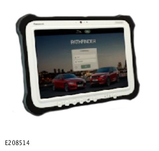
This procedure requires a minimum of Pathfinder 259 loaded or later.
NOTE:The Jaguar Land Rover (JLR) approved diagnostic equipment will read the Vehicle Identification Number (VIN) for the vehicle and automatically take the vehicle out of ‘Transportation mode’ if required.
Connect the JLR approved battery support unit. - Connect the JLR approved diagnostic equipment to the vehicle and begin a new session.
- Follow the JLR approved diagnostic equipment prompts.
- Select 'ECU Diagnostics'.
- Select 'All Diagnostic Trouble Code(s) (DTC)s'.
- If there areDTCs stored in the Remote Function Actuator (RFA), do not continue with this technical bulletin and continue with diagnosis (see TOPIx Workshop Manual section 419-01: Anti-Theft - Passive - Diagnosis and Testing - Anti-Theft - Passive).
- If there are noDTCs stored in the RFA, continue to the service instruction.
SERVICE INFORMATION:
NOTE:
Some components have been removed for clarity.
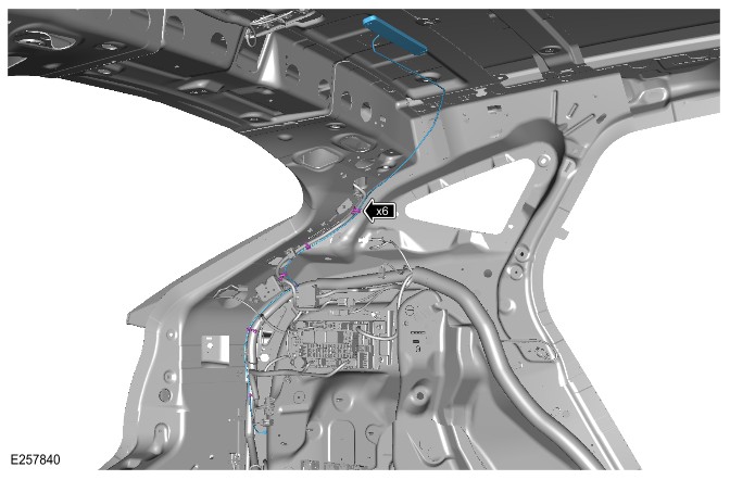 E-PACE - Coaxial cable wiring harness route.
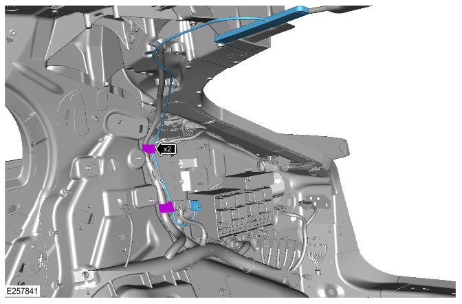 I-PACE - Coaxial cable wiring harness route.
SERVICE INSTRUCTION:
NOTES:
- If the keyless entry functionality is correct, do not continue with this technical bulletin. Continue diagnosis using the JLR approved diagnostic equipment and see TOPIx workshop manual.
- Check the voltage of the smart key battery and renew if required.
- The coaxial cable and RF receiver cannot be renewed separately.
E-PACE vehicles only
- Remove the left loadspace trim panel (see TOPIx Workshop Manual section 501-05: Interior Trim and Ornamentation - Removal and Installation - Loadspace Trim Panel).
- NOTE:
Do not remove the headliner from the vehicle.
Lower the headliner for access (see TOPIx Workshop Manual section 501-05: Interior Trim and Ornamentation - Removal and Installation - Headliner). - Inspect the coaxial cable from the RF receiver to the RFA is correctly routed, secured in position and is not trapped. Inspect the condition of the connectors, connector pins between the RF receiver and RFA for damage, make sure that connections are secure. Refer to the 'Service Information' section for wiring harness routes and locations.
- If the coaxial cable is found to be incorrectly routed or trapped, but no damage has occurred, continue to step 4.
- If the coaxial cable and/or connectors and connector pins are found to be damaged, continue to step 5.
- If the coaxial cable is not found to be damaged, incorrectly routed or trapped, continue with diagnosis (see TOPIx Workshop Manual section 419-01: Anti-Theft - Passive - Diagnosis and Testing - Anti-Theft - Passive).
- Refer to the 'Service Information' section to correctly re-route the coaxial cable.
- NOTE:
Make sure the RF receiver is secured correctly by applying gentle pressure to both sides of the antenna body only, and not in the middle section.
Renew the RF receiver and coaxial cable (see TOPIx Workshop Manual section 419-10: Multifunction Electronic Modules - Removal and Installation - Radio Frequency Receiver).- Refer to the 'Service Information' section to make sure the coaxial cable is correctly routed.
- Install the headliner (see TOPIx Workshop Manual section 501-05: Interior Trim and Ornamentation - Removal and Installation - Headliner).
- Install the left loadspace trim panel (see TOPIx Workshop Manual section 501-05: Interior Trim and Ornamentation - Removal and Installation - Loadspace Trim Panel).
- Remove the right loadspace trim panel (see TOPIx Workshop Manual section 501-05: Interior Trim and Ornamentation - Removal and Installation - Loadspace Trim Panel).
- NOTE:
Do not remove the headliner from the vehicle.
Lower the headliner for access (see TOPIx Workshop Manual section 501-05: Interior Trim and Ornamentation - Removal and Installation - Headliner). - Inspect the coaxial cable from the RF receiver to the RFA is correctly routed, secured in position and is not trapped. Inspect the condition of the connectors, connector pins between the RF receiver and RFA for damage, make sure that connections are secure. Refer to the 'Service Information' section for wiring harness routes and locations.
- If the coaxial cable is found to be incorrectly routed or trapped, but no damage has occurred, continue to step 11.
- If the coaxial cable and/or connectors and connector pins are found to be damaged, continue to step 12.
- If the coaxial cable is not found to be damaged, incorrectly routed or trapped, continue with diagnosis (see TOPIx Workshop Manual section 419-01: Anti-Theft - Passive - Diagnosis and Testing - Anti-Theft - Passive).
- Refer to the 'Service Information' section to correctly re-route the coaxial cable.
- NOTE:
Make sure the RF receiver is secured correctly by applying gentle pressure to both sides of the antenna body only, and not in the middle section.
Renew the RF receiver and coaxial cable (see TOPIx Workshop Manual section 419-10: Multifunction Electronic Modules - Removal and Installation - Radio Frequency Receiver).- Refer to the 'Service Information' section to make sure the coaxial cable is correctly routed.
- Install the headliner (see TOPIx Workshop Manual section 501-05: Interior Trim and Ornamentation - Removal and Installation - Headliner).
- Install the right loadspace trim panel (see TOPIx Workshop Manual section 501-05: Interior Trim and Ornamentation - Removal and Installation - Loadspace Trim Panel).
I-PACE vehicles only