Range Rover Sport / L494 2017 ELECTRICAL BATTERY AND CHARGING SYSTEM
414-00: Battery and Charging System - General Information
414-01: Battery, Mounting and Cables
2017.0 RANGE ROVER SPORT (LW), 414-01
BATTERY, MOUNTING AND CABLES (G1341944)
Torque Specifications
| DESCRIPTION | NM | LB-FT | LB-IN |
|---|---|---|---|
| Startup battery mounting strap bolt | 9 | - | 80 |
| Startup battery terminal connector | 6 | - | 53 |
| Auxiliary battery clamp bolt | 9 | - | 80 |
| Auxiliary battery terminal connector | 6 | - | 53 |
| Electric Power Inverter Converter (EPIC) mounting bolts | 9 | - | 80 |
| EPIC coolant pump mounting bolt | 6 | - | 53 |
| High Voltage (HV) cable mounting bolts | 10 | 7 | - |
| Electric vehicle mode switch mounting bolts | 2 | - | 17 |
| Suspension air supply unit mounting bolt | 10 | 7 | - |
| Suspension air supply unit mounting nut | 25 | 18 | - |
Description and Operation
2017.0 RANGE ROVER SPORT (LW), 414-01
BATTERY, MOUNTING AND CABLES
BATTERY AND CABLES (G1950059)
COMPONENT LOCATION - 1 OF 3 - VEHICLES WITH SINGLE BATTERY SYSTEM
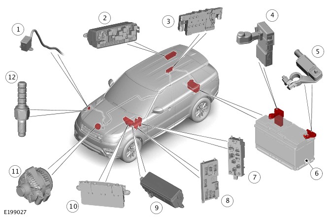
| ITEM | DESCRIPTION |
|---|---|
| 1 | Jump start terminal - Positive |
| 2 | Rear Junction Box (RJB) |
| 3 | Battery Junction Box (BJB) |
| 4 | Megafuse |
| 5 | Battery Monitoring System (BMS) sensor |
| 6 | Battery |
| 7 | Passenger Junction Box (PJB) |
| 8 | Body Control /Gateway Module (BCM/GWM) assembly |
| 9 | Engine Junction Box (EJB) |
| 10 | Auxiliary Junction Box (AJB) |
| 11 | Generator |
| 12 | Jump start terminal - Ground |
COMPONENT LOCATION - 2 OF 3 - SINGLE BATTERY SYSTEM WITH STOP/START SYSTEM - ALL VEHICLES, EXCEPT COLD CLIMATE TDV6 3.0L DIESEL ENGINE AND TDV8 4.4L DIESEL ENGINE VEHICLES
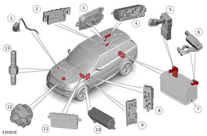
| ITEM | DESCRIPTION |
|---|---|
| 1 | Jump start terminal - Positive |
| 2 | Battery Junction Box (BJB) |
| 3 | Voltage Quality Module (VQM) |
| 4 | Rear Junction Box (RJB) |
| 5 | Megafuse |
| 6 | Battery Monitoring System (BMS) sensor |
| 7 | Battery |
| 8 | Passenger Junction Box (PJB) |
| 9 | Body Control Module/Gateway Module (BCM/GWM) assembly |
| 10 | Engine Junction Box (EJB) |
| 11 | Auxiliary Junction Box (AJB) |
| 12 | Generator |
| 13 | Jump start terminal - Ground |
COMPONENT LOCATION - 3 OF 3 - DUAL BATTERY SYSTEM - TDV8 4.4L DIESEL ENGINE AND COLD CLIMATE TDV6 3.0L DIESEL ENGINE VEHICLES
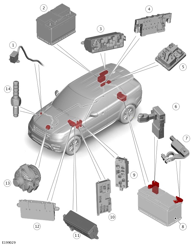
| ITEM | DESCRIPTION |
|---|---|
| 1 | Jump start terminal - Positive |
| 2 | Auxiliary battery |
| 3 | Rear Junction Box (RJB) |
| 4 | Battery Junction Box (BJB) |
| 5 | Power Supply Distribution Box (PSDB) |
| 6 | Megafuse |
| 7 | Battery Monitoring System (BMS) sensor |
| 8 | Primary battery |
| 9 | Passenger Junction Box (PJB) |
| 10 | Body Control Module/Gateway Module (BCM/GWM) assembly |
| 11 | Engine Junction Box (EJB) |
| 12 | Auxiliary Junction Box (AJB) |
| 13 | Generator |
| 14 | Jump start terminal - Ground |
The primary battery provides power to the Battery Junction Box (BJB) which delivering power to the:
- Body Control Module/Gateway Module (BCM/GWM) assembly
- Passenger Junction Box (PJB)
- Engine Junction Box (EJB)
- Rear Junction Box (RJB)
- Auxiliary Junction Box (AJB)
- Voltage Quality Module (VQM) - Single battery system with auto stop/start system only - All vehicles, except cold climate TDV6 3.0L diesel engine and TDV8 4.4L diesel engine vehicles
- Power Supply Distribution Box (PSDB) - Dual battery system only - TDV8 4.4L diesel engine and cold climate TDV6 3.0L diesel engine vehicles
- Jump start terminal - Positive
- Starter motor and generator.
The junction boxes contain fusible links, fuses, and relays to distribute electrical power to various vehicle systems.
A Battery Monitoring System (BMS) sensor is mounted on the primary battery negative terminal. The BMS sensor is integral with the primary battery ground cable and is controlled by the BCM/GWM assembly.
The auxiliary battery is not equipped with a BMS sensor.
When connecting a slave power supply to the vehicle, always use the ground terminal stud point on the right side top mount in the engine compartment. Never connect directly to the battery negative terminal, because the BMS sensor can be damaged.
If a new primary battery is fitted to the vehicle, the BMS sensor will require re-calibrating using a Land Rover approved diagnostic equipment. This will also apply if a new auxiliary battery is fitted to TDV8 4.4L diesel and TDV6 3.0L diesel cold climate vehicles.
The BCM/GWM assembly is the main controller of the vehicle body systems. The BCM/GWM assembly contains most of the software required to control the battery charging system and components. The BCM/GWM assembly monitors the components and can store fault related Diagnostic Trouble Codes (DTCs).
The dual battery system is used on TDV8 4.4L diesel engine and TDV6 3.0L diesel engine vehicles in cold climate markets with or without stop/start system. The dual battery system prevents the vehicle electrical systems from being subjected to undesirably low voltages during repeated engine restarts. If the electrical systems are subject to low voltages the user may notice degraded performance of components and systems. In this case incorrect fault Diagnostic Trouble Codes (DTCs) may be stored.
The dual battery system switches the auxiliary battery in parallel with the primary battery if:
- The ambient temperature falls below a certain threshold
- The state of charge of the primary battery falls below a certain level.
Thereby the auxiliary battery is able to assist the primary battery in cranking the car at a suitable speed to provide a start.
Monitoring of the primary and auxiliary battery condition is controlled by the BCM/GWM assembly and the BMS sensor.
POWER MODES
The Body Control Module/Gateway Module (BCM/GWM) assembly controls the power supplies for the various vehicle functions. There are nine power modes available to determine the operating condition of the vehicle.
Only five of these modes will be noticeable to the driver and technicians as follows:
- Power mode 0 - Ignition off
- Power mode 4 - Accessory
- Power mode 6 - Ignition on
- Power mode 7 - Engine running
- Power mode 9 - Crank before engine running.
TRANSIT MODE
All new vehicles will be delivered from the factory in transit mode. Transit mode replaces the traditional transit relay and inhibits a number of electrical systems and features to eliminate quiescent drain from the battery during delivery. Transit mode also inhibits some electrical loads when the engine is running to provide that the battery is never discharged while the engine is running.
To remove the vehicle from transit mode, the Land Rover approved diagnostic equipment must be connected during the Pre-Delivery Inspection (PDI). For additional information, refer to:Preliminary (101-01 Pre-Delivery Inspection Manual, Description and Operation).
Two jump start terminals are located adjacent to the right side top mount in the engine compartment. A cover protects the positive terminal when not in use. If jump starting is required, the cover must be removed and the positive jump lead attached securely. The cover must be equipped to the positive terminal when not in use. The negative jump lead is attached to a stud located on the right side top mount.
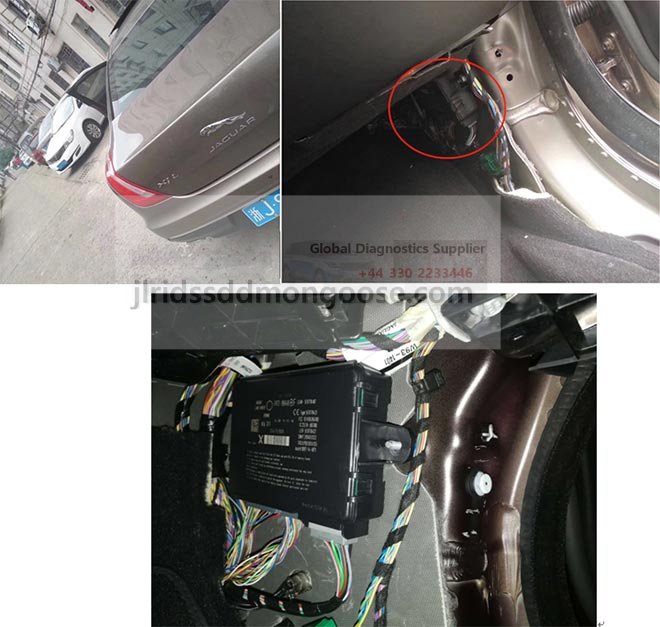
PRIMARY AND AUXILIARY BATTERY AND BATTERY MONITORING SYSTEM SENSOR
The auxiliary battery is not equipped with a Battery Monitoring System (BMS) sensor.
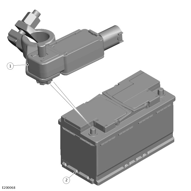
| ITEM | DESCRIPTION |
|---|---|
| 1 | Battery Monitoring System (BMS) sensor |
| 2 | Primary battery |
The primary battery is located in a plastic tray under the luggage compartment floor in a central position in the luggage compartment.
The auxiliary battery is located on the right side of the luggage compartment on a battery support tray. The auxiliary battery negative terminal is connected via a cable to the vehicle body. The positive terminal is connected by a cable to the Power Supply Distribution Box (PSDB).
Both of the batteries are vented via a tube which passes through a grommet in the floorpan. Both of the batteries are secured with a strap, threaded rods and a clamp bolted to a tray.
Above the dual battery cold start temperature threshold, and above a certain primary battery state of charge:
- The dual battery system isolates all electrical components and systems sensitive to low supply voltage from the primary battery while an engine start is in progress.
- The isolated components and systems are supplied from the auxiliary battery.
Without the dual battery system, the electrical power required by the starter motor to crank the engine for each start would cause a voltage drop. The voltage drop across the entire vehicle electrical network causes control modules to function incorrectly. The voltage drops causes in some cases reset and/or record Diagnostic Trouble Codes (DTCs).
The primary battery on petrol and diesel vehicles is a 90Ahr, 850A CCA Absorbed Glass Mat (AGM) Valve Regulated Lead-Acid (VRLA) battery.
The auxiliary battery is a 70Ahr, 760A CCA Absorbed Glass Mat (AGM) Valve Regulated Lead-Acid (VRLA) battery.
Battery Monitoring System sensor
The Battery Monitoring System (BMS) sensor is located on the battery negative terminal, and receives a 12 V power supply direct from the primary battery positive terminal. It is connected to the Body Control Module/Gateway Module (BCM/GWM) assembly via a Local Interconnect Network (LIN) bus connection. The BMS sensor contains software maps that provide a mathematical model of battery conditions, and constantly transmits information to the BCM/GWM assembly regarding the vehicle state and electrical loading.
When connecting a slave power supply to the vehicle, always use the ground terminal stud point on the right side top mount in the engine compartment. Never connect directly to the battery negative terminal, because the BMS senso can be damaged.
The BMS sensor monitors various battery parameters, which are directly measured or predictive values:
- Battery current and voltage are the result of direct measurement.
- State of Charge, State of Function and electrolyte temperature are predicted values.
These signals are used by both the charging system and the auto stop/start system to ensure the vehicle functions are optimized. The measurement is autonomous and happens in all states to enable an accurate condition of the battery to be assessed at all times. Software based values are calculated and used as a backup in the event of a system fault condition. If any of the measured/predicted values do not meet the necessary thresholds, the auto stop/start feature will be suspended until the thresholds are met. In the case of a fault condition, the auto stop/start system will be disabled for the duration of the particular drive cycle. A Diagnostic Trouble Code (DTC) relating to faults will be stored in the BCM/GWM assembly.
Due to the self-calibration routine, it is recommended that all power supply diagnostic testing is carried out using the Land Rover approved diagnostic equipment rather than a digital multimeter.
The BMS sensor Diagnostic Trouble Codes (DTCs) can be used to help diagnose BMS faults. The DTCs are stored in BCM/GWM assembly. These DTCs can be read using the Land Rover approved diagnostic equipment. The Land Rover approved diagnostic equipment has a process for an automated power supply diagnostic procedure. The procedure provides a menu driven process to locate a fault in a logical sequence. The procedure uses the capability of the BMS sensor and generator LIN bus controlled functions. These functions provide current flow information and will detect if the BMS sensor or generator are functioning correctly.
The BMS sensor also has a hardwired connection to the battery positive terminal. This connection is used to avoid any potential voltage drop in the circuit which results incorrect information received by the BMS sensor. If this connection becomes open, the BCM/GWM assembly detects a communication loss with the BMS sensor. Then the BCM/GWM assembly default to a fail-safe fixed charging voltage of 14 Volts, stores a related DTC, and sends a message to the Instrument Cluster (IC) via the High Speed (HS) Controller Area Network (CAN) comfort systems bus to illuminate the charge warning indicatorFor additional information, refer to:Instrument Cluster (413-01 Instrument Cluster, Description and Operation)..
VOLTAGE QUALITY MODULE
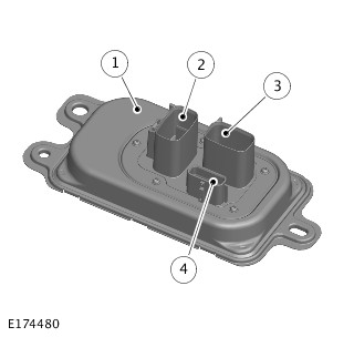
| ITEM | DESCRIPTION |
|---|---|
| 1 | Voltage Quality Module (VQM) |
| 2 | Power connector |
| 3 | Ground connector |
| 4 | Signal connector |
The Voltage Quality Module (VQM) is located adjacent to the Rear Junction Box (RJB) in the right side of the luggage compartment. The VQM is attached to the rear floor with three bolts. The VQM consists of a Direct Current (DC) - DC converter and an interface. This interface provides the communication with the Body Control Module/Gateway Module (BCM/GWM) assembly.
The DC - DC converter can produce a constant 12 V output voltage from the varying input voltage supplied by the battery during an engine restart. This constant 12 V output voltage is needed for the crucial vehicle systems.
The VQM supplies a constant voltage during an engine restart for the following:
- The Instrument Cluster (IC)
- The infotainment system components - Depends on equipment
- The Rear View Mirror (RVM) - If equipped
- The Parking Assist Control Module (PACM) - If equipped
- The Rear View Camera (RVC) - If equipped
- The left and right Blind Spot Monitoring Control Module (BMCM) - If equipped.
The VQM has three connections:
- Two power connectors:
- A battery feed connection from the Battery Junction Box (BJB) via a 60 A fuse
- A power output connection to the Rear Junction Box (RJB).
- An additional connector to provide electrical connection to the other modules and ground.
The VQM receives an ignition signal from the BCM/GWM assembly, and a crank signal from the starter motor relay located in the Engine Junction Box (EJB). The VQM sends status and diagnostic messages to the BCM/GWM assembly via a Local Interconnect Network (LIN) bus connection.
BODY CONTROL MODULE/GATEWAY MODULE ASSEMBLY
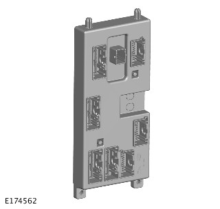
The Body Control Module/Gateway Module (BCM/GWM) assembly is attached to a bracket, which is bolted to the passenger side of the cross-car beam, behind the instrument panel.
The BCM/GWM assembly is located adjacent to the Passenger Junction Box (PJB), and it is the main controller of the vehicle body systems.
The BCM/GWM assembly contains software to control the following functions:
- Determine condition of primary and auxiliary batteries.
- Generator output. Control the generator output to reach a desired system voltage or target battery state of charge.
- Load management. Load management can control off certain loads in the event of stop/start events and the 12 V power system being overloaded.
- Control stop/start system functionality. The BCM/GWM assembly can only inhibit stop/start functionality depending on power system condition. The BCM/GWM assembly also provides supporting functionality via load management and Power Supply Distribution Box (PSDB) / Voltage Quality Module (VQM) control.
- Control the PSDB to enable the switching of the battery inputs.
The BCM/GWM assembly communicates with other system control modules on the followings:
- High Speed (HS) Controller Area Network (CAN) powertrain systems bus
- HS CAN power mode zero systems bus
- HS CAN chassis systems bus
- HS CAN comfort systems bus
- Medium Speed (MS) CAN body systems bus
- Over the flexray network system.
The BCM/GWM assembly communicates with the BMS sensor, the PSDB, the VQM, and the generator via a Local Interconnect Network (LIN) bus.
POWER SUPPLY DISTRIBUTION BOX
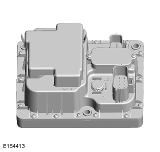
The Power Supply Distribution Box (PSDB) is located in the right side of the luggage compartment, rearward of the Battery Junction Box (BJB). The PSDB incorporates two banks of Metal Oxide Semi-conductor Field Effect Transistors (MOSFETs).
The MOSFETs are activated by the Body Control Module/Gateway Module (BCM/GWM) assembly:
- To switch the vehicle loads between the batteries during an auto stop/start event
- For charging the auxiliary battery.
The PSDB receives a battery supply direct from the primary battery to BAT1 terminal and a battery supply from the auxiliary battery to BAT2 terminal. The PSDB also incorporates a microcontroller, which receives commands from the BCM/GWM assembly via a Local Interconnect Network (LIN) bus connection. The PSDB connects or disconnects either the primary or auxiliary battery to the vehicle loads according to the BCM/GWM assembly commands. In addition, there is a diagnostic connection between the BCM/GWM assembly and PSDB, to detect faults with the PSDB.
The MOSFETs in the PSDB have a fail-safe body diode mode. This mode will provide there is always a connection from the primary battery to the vehicle loads in the event of a failure in the PSDB. At least 60 A can be supplied to the loads in this mode. The BCM/GWM assembly will detect such a failure and will shut down non-essential loads so as not to overload the PSDB.
BATTERY MONITORING SYSTEM SENSOR
When the ignition is off (power mode 0), the Battery Monitoring System (BMS) sensor records the primary battery state of charge.
If the battery state of charge falls by 7 % from the critical start point, the BMS sensor will start to monitor the battery for five minutes. The BMS sends a 'Warning' message on the Local Interconnect Network (LIN) bus to the Body Control Module/Gateway Module (BCM/GWM) assembly. The BMS sensor will determine that the control modules are still 'awake' if the battery charge has continued to fall below 50 %. When this occurs the BMS sensor sends a 'Shut down' message on the LIN bus to the BCM/GWM assembly. The BCM/GWM assembly then transmits a 'Shut down' message on the Controller Area Network (CAN) buses to all control modules, requesting them to shut down.
The BMS sensor will monitor the battery state of charge for a further 15 minutes. The BMS sensor determine if the battery state of charge is still dropping due to the quiescent drain current. The BMS sensor sends a 'Power Disconnect' signal to the BCM/GWM assembly on the LIN bus. The BCM/GWM assembly then sends a signal to the Rear Junction Box (RJB) to open its internal relays. When the relays are open, the power supply from the battery to non-critical control modules is removed. The non-critical control modules are any modules associated with the infotainment system and also the climate control system.
The use of the LIN bus communication provides that no other control modules are 'woken' during this process. If CAN bus communication was used, all modules on the CAN bus would be woken by the message.
The BCM/GWM assembly contains most of the software required to control the battery charging system and components. The BCM/GWM assembly monitors the components and the status of the stop/start system, and can store fault related Diagnostic Trouble Codes (DTCs). The BCM/GWM assembly contains the Intelligent Power Management System (IPMS). The BMS software is contained within the BMS sensor and communicates with the IPMS on the LIN bus. The IPMS uses information from the BMS in order to determine the condition of the batteries.
The BCM/GWM assembly software will monitor the state of charge of the battery and will determine when an auto stop/start event can occur. It can also intervene to maintain vehicle systems by keeping the engine running or initiating a restart. For example, climate control system requirements or request for restart from the Powertrain Control Module (PCM). A brake pressure signal is received from the PCM which will indicate to the BCM/GWM assembly that an engine restart is required. The foot brake pedal is operated by the driver.
BATTERY MONITORING SYSTEM SENSOR LOW BATTERY WARNING AND ENERGY MANAGEMENT MESSAGES
The Battery Monitoring System (BMS) sensor continuously monitors the condition of the primary battery. If excessive primary battery discharge occurs, the system will begin to shut down non-essential electrical systems in order to protect the battery.
The BMS sensor displays warning messages to inform the driver:
- The battery is either at a low level of charge
- The engine-off power consumption limit has been exceeded.
Low Battery - 'Please switch engine on or system will shutdown in 3 minutes'
This message will be displayed as a warning on the Touch Screen (TS) if the engine is not running. This indicates that the primary battery charge has fallen below a predefined threshold. As soon as the primary battery is charged above this threshold, the message will be removed.
Low Battery - 'Please start your engine'
This message will be displayed on the message center if the engine is not running. This indicates that the primary battery charge has fallen below a predefined threshold. As soon as the primary battery is charged above this threshold, the message will be removed. This message can be manually removed by pressing the 'OK' switch on the steering wheel switchpack.
'System will shut down in 3 minutes'
This message will be displayed as an energy management message on the TS. This message appears if the engine is not running and system features are causing excessive battery discharge. After three minutes the Body Control Module/Gateway Module (BCM/GWM) assembly will begin shutting down vehicle systems. Normal system operation will resume when the engine is started.
These messages are based on a percentage of the battery capacity available for the driver to use the vehicle systems with the engine off. The percentage can change based upon several factors. Once activated, the resetting of these messages will not occur until the vehicle is driven for ten minutes with the engine running. This time allows to the battery to replace any lost charge. However, if the engine is run for less than ten minutes, the messages will only be displayed after an additional five minutes. This occurs, when the ignition is switched on but the engine is not running.
BATTERY MONITORING SYSTEM SENSOR SELF CALIBRATION
The Battery Monitoring System (BMS) sensor periodically initiates a self-calibration routine. To self-calibrate, the BMS charges the primary battery to its full condition.
If the vehicle is only driven for short periods the charging process could take a number of days to complete.
When the primary battery is fully charged the system then resumes normal charging control. The optimum level of charge will be between 12.6 V and 15 V, depending on primary battery condition, temperature and loading.
The BMS sensor also monitors the primary battery condition with the engine switched off. If a low voltage condition is detected the BMS sensor can request the infotainment system is switched off to protect primary battery voltage.
VOLTAGE QUALITY MODULE
During a warm engine restart, significant low voltage transients occur in the vehicle electrical systems. The Voltage Quality Module (VQM) is a Direct Current (DC) - DC converter and produce a constant 12 V output voltage from a varying (and lower) input voltage.
A = BATTERY VOLTAGE: B = GROUND: C = BATTERY CHARGING VOLTAGE.
| ITEM | DESCRIPTION |
|---|---|
| 1 | Voltage Quality Module (VQM) |
| 2 | Rear Junction Box (RJB) |
| 3 | Voltage sensitive loads 1 |
| 4 | Voltage sensitive loads 2 |
| 5 | Electric loads |
| 6 | Battery Monitoring System (BMS) sensor |
| 7 | Battery |
| 8 | Generator |
| 9 | Starter motor |
Bypass mode is the VQMs normal operating mode. In this mode the power from the battery to the voltage sensitive loads passes through on the VQM without any intervention. The VQM can support 600 W of continuous power in bypass mode.
A = BATTERY VOLTAGE: B = GROUND: C = BATTERY CHARGING VOLTAGE.
| ITEM | DESCRIPTION |
|---|---|
| 1 | Voltage Quality Module (VQM) |
| 2 | Rear Junction Box (RJB) |
| 3 | Voltage sensitive loads 1 |
| 4 | Voltage sensitive loads 2 |
| 5 | Electric loads |
| 6 | Battery Monitoring System (BMS) sensor |
| 7 | Battery |
| 8 | Generator |
| 9 | Starter motor |
During a warm engine restart a hardwired connection from the starter motor relay provides the crank signal to the VQM. At this point the VQM switches into boost mode, and activates the Direct Current (DC) - DC converter. The DC - DC converter maintains a constant output voltage between 11 V and 14 V (depending on the input voltage) to the voltage sensitive loads for five seconds. The VQM can support 450 W of continuous power in boost mode. After the engine has restarted, and the voltage at the battery terminal will ramp up, the VQM returns to bypass mode.
Boost mode is inhibited at ambient temperatures below 0 °C (32 °F), when auto stop/start function is disabled.
ELECTRICAL LOAD MANAGEMENT
The Body Control Module/Gateway Module (BCM/GWM) assembly contains the electrical load management. The electrical load management uses the Intelligent Power Management System (IPMS) functionality and is based on Battery Monitoring System (BMS) sensor inputs. The BCM/GWM assembly will monitor the vehicle system power loads before and during an auto engine stop.
Before an auto engine stop, the BCM/GWM assembly will transmit a signal to the system control modules on all Controller Area Network (CAN) buses. The BCM/GWM assembly requests a power save on all electrical loads and set a minimum electrical value override. The BCM/GWM assembly monitors the vehicle electrical loads. It will inhibit an auto engine stop until the load current is at a value low enough to be supported by the battery. If the electrical loads cannot be reduced sufficiently, the BCM/GWM assembly will inhibit the auto engine stop.
When the engine is stopped after an auto engine stop, the BCM/GWM assembly will continue to monitor the battery state of charge. If battery voltage falls below 11.0 V, the BCM/GWM assembly will initiate an engine start. The 11.0 V is a level which will result in degraded starting performance or possible battery damage.
SYSTEM INHIBITS
The auto stop/start inhibit monitoring of the battery is performed by the Body Control Module/Gateway Module (BCM/GWM) assembly. If the battery voltage is too low to support an auto stop/start, then the BCM/GWM assembly will suspend auto stop/start.
The BCM/GWM assembly monitors the battery and the Voltage Quality Module (VQM). Any fault found will cause the BCM/GWM assembly to inhibit auto stop/start and the BCM/GWM assembly will record a Diagnostic Trouble Code (DTC).
DUAL BATTERY SYSTEM - TDV8 4.4L DIESEL ENGINE AND COLD CLIMATE TDV6 3.0L DIESEL ENGINE VEHICLES
The dual battery system on vehicles with an auxiliary battery, allows both batteries to be connected in parallel. The dual battery system provides increased amperage to the starter motor for efficient starting in cold climates. The auxiliary battery assists the primary battery in operating the starter motor to crank the engine at a sufficient speed for efficient starting.
In addition, the auxiliary battery supplies the sensitive loads when the auto stop/start is active.
The PSDB connects or isolates the batteries on receipt of Local Interconnect Network (LIN) bus information from the Body Control Module/Gateway Module (BCM/GWM) assembly.
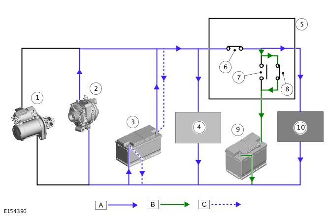
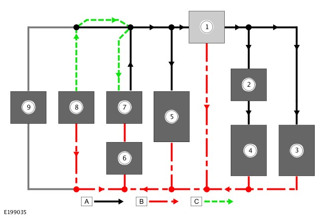
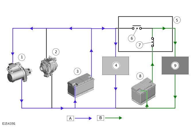
A = PRIMARY BATTERY/GENERATOR SUPPLY: B = AUXILIARY BATTERY CHARGING: C = PRIMARY BATTERY CHARGING.
| ITEM | DESCRIPTION |
|---|---|
| 1 | Starter motor / Tandem Solenoid Starter (TSS) motor |
| 2 | Generator |
| 3 | Primary battery |
| 4 | Power and engine management system loads |
| 5 | Power Supply Distribution Box (PSDB) |
| 6 | Battery 1 connection on Power Supply Distribution Box (PSDB) - Connected |
| 7 | Battery 2 connection on Power Supply Distribution Box (PSDB) - Disconnected |
| 8 | Battery 2 connection on Power Supply Distribution Box (PSDB) - Connected |
| 9 | Auxiliary battery |
| 10 | Sensitive loads |
When the engine is running, all electrical systems are powered from the primary battery and the generator. The BCM/GWM assembly and the Power Supply Distribution Box (PSDB) communicate via the LIN bus, and the PSDB isolates the auxiliary battery from the system.
The BCM/GWM assembly monitors the state of charge of both the primary and auxiliary batteries. The BCM/GWM assembly provides that sufficient voltage is available for the next auto stop/start engine start. The BCM/GWM assembly can apply charging to the auxiliary battery via the PSDB, if it is required. If the charging of auxiliary battery is necessary, the PSDB connects the auxiliary battery, and the generator starts to charge it.
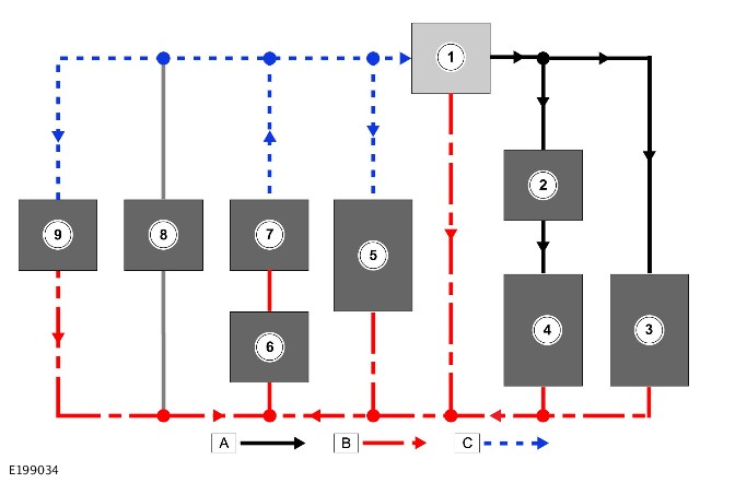
A = PRIMARY BATTERY SUPPLY: B = AUXILIARY BATTERY SUPPLY.
| ITEM | DESCRIPTION |
|---|---|
| 1 | Starter motor / Tandem Solenoid Starter (TSS) motor |
| 2 | Generator |
| 3 | Primary battery |
| 4 | Power and engine management system loads |
| 5 | Power Supply Distribution Box (PSDB) |
| 6 | Battery 1 connection on Power Supply Distribution Box (PSDB) - Connected |
| 7 | Battery 2 connection on Power Supply Distribution Box (PSDB) - Connected |
| 8 | Auxiliary battery |
| 9 | Sensitive loads |
When the ambient temperature is below a predetermined level and the BCM/GWM assembly receives a start signal the following occurs:
- The BCM/GWM assembly communicates with the PSDB via the LIN bus to keep the primary battery connected, and also connect the auxiliary battery. The power for the starter motor is supplied from both batteries.
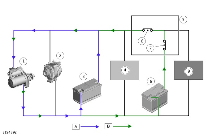
A = PRIMARY BATTERY SUPPLY: B = AUXILIARY BATTERY SUPPLY.
| ITEM | DESCRIPTION |
|---|---|
| 1 | Tandem Solenoid Starter (TSS) motor |
| 2 | Generator |
| 3 | Primary battery |
| 4 | Power and engine management system loads |
| 5 | Power Supply Distribution Box (PSDB) |
| 6 | Battery 1 connection on Power Supply Distribution Box (PSDB) - Disconnected |
| 7 | Battery 2 connection on Power Supply Distribution Box (PSDB) - Connected |
| 8 | Auxiliary battery |
| 9 | Sensitive loads |
When the auto stop/ start is required, the BCM/GWM assembly sends a signal to the PSDB via the LIN bus. The PSDB isolates the primary battery from sensitive loads. The primary battery supplies the starter motor and power loads only, to provide the quick engine start. In same time the PSDB connects the auxiliary battery to supply the sensitive loads, while the auto stop/start in progress.
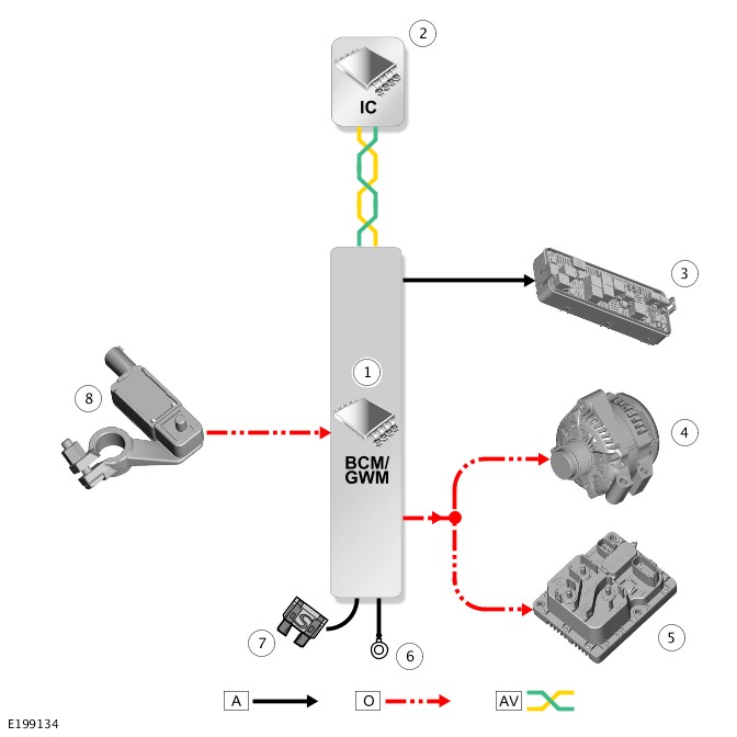
CONTROL DIAGRAM - 1 OF 3 - SINGLE BATTERY SYSTEM
A = HARDWIRED: O = LOCAL INTERCONNECT NETWORK (LIN) BUS: AV = HIGH SPEED (HS) CONTROLLER AREA NETWORK (CAN) COMFORT SYSTEM BUS.
| ITEM | DESCRIPTION |
|---|---|
| 1 | Body Control Module/Gateway Module (BCM/GWM) assembly |
| 2 | Instrument Cluster (IC) |
| 3 | Generator |
| 4 | Voltage Quality Module (VQM) - Vehicles with auto stop/start system, except cold climate TDV6 3.0L diesel engine and TDV8 4.4L diesel engine vehicles |
| 5 | Rear Junction Box (RJB) |
| 6 | Ground |
| 7 | Power supply |
| 8 | Battery Monitoring System (BMS) sensor |
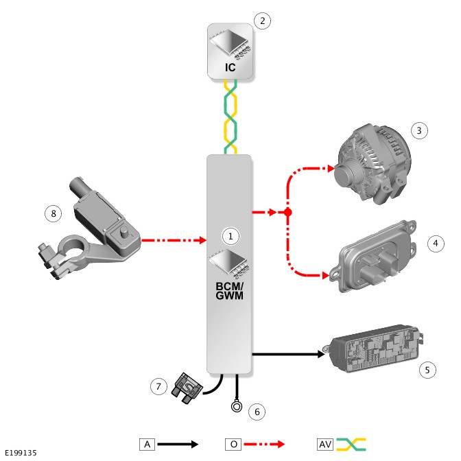
CONTROL DIAGRAM - 2 OF 3 - DUAL BATTERY SYSTEM - TDV8 4.4L DIESEL ENGINE AND COLD CLIMATE TDV6 3.0L DIESEL ENGINE VEHICLES
A = HARDWIRED: O = LOCAL INTERCONNECT NETWORK (LIN) BUS: AV = HIGH SPEED (HS) CONTROLLER AREA NETWORK (CAN) COMFORT SYSTEM BUS.
| ITEM | DESCRIPTION |
|---|---|
| 1 | Body Control Module/Gateway Module (BCM/GWM) assembly |
| 2 | Instrument Cluster (IC) |
| 3 | Rear Junction Box (RJB) |
| 4 | Generator |
| 5 | Power Supply Distribution Box (PSDB) |
| 6 | Ground |
| 7 | Power supply |
| 8 | Battery Monitoring System (BMS) sensor |
VOLTAGE QUALITY MODULE
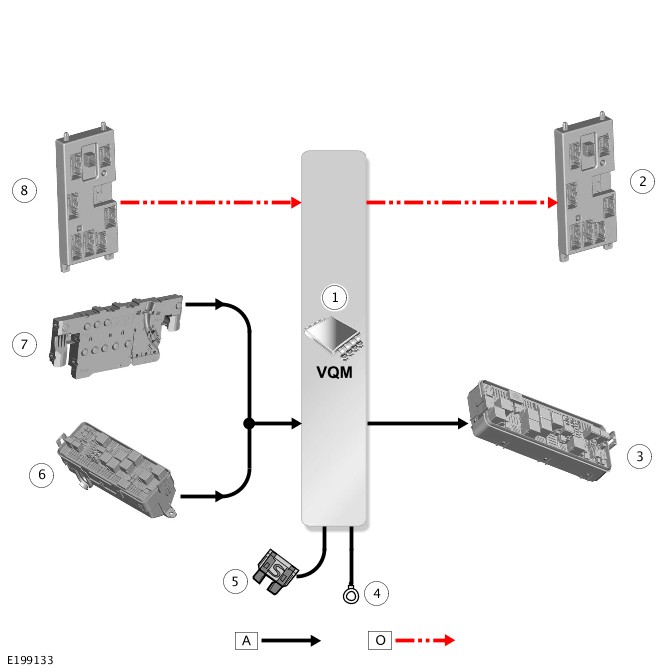
A = HARDWIRED: O = LOCAL INTERCONNECT NETWORK (LIN) BUS.
| ITEM | DESCRIPTION |
|---|---|
| 1 | Voltage Quality Module (VQM) |
| 2 | Status and diagnostic messages to the Body Control Module/Gateway Module (BCM/GWM) assembly |
| 3 | Rear Junction Box (RJB) |
| 4 | Ground |
| 5 | Power supply |
| 6 | Crank signal from the starter motor relay located in the Engine Junction Box (EJB) |
| 7 | Battery Junction Box (BJB) |
| 8 | Ignition signal from the Body Control Module/Gateway Module (BCM/GWM) assembly |
Diagnosis and Testing
2017.0 RANGE ROVER SPORT (LW), 414-01
BATTERY, MOUNTING AND CABLES
BATTERY - VEHICLES WITH: 8HP70H 8-SPEED AUTOMATIC TRANSMISSION, VEHICLES WITH: SDV6 3.0L DIESEL - HYBRID ELECTRIC VEHICLE (G1676855)
For a detailed description of the Battery, Mounting and Cables, refer to the relevant Description and Operation section in the workshop manual. REFER to:Battery and Cables (414-01 Battery, Mounting and Cables, Description and Operation).
-
A risk assessment must be performed before any work is undertaken.
-
All hybrid electric vehicle work must be performed by a suitably qualified person.
-
Appropriate Personal Protection Equipment (PPE) must be worn when working on or near a hybrid electric vehicle high voltage system.
-
The hybrid electric vehicle battery pack casing must not be opened due to the risk of exposure to hazardous voltage, which may cause serious injury or death.
-
The electric power inverter converter casing must not be disassembled due to the risk of exposure to hazardous voltage, which may cause serious injury or death.
-
If the hybrid electric vehicle battery pack is damaged or overcharged, there is a risk of exposure to hazardous voltage and/or highly corrosive electrolyte mist. If liquid or vapour is observed leaking from the hybrid electric vehicle battery pack, take the following action:
- Evacuate the area
- Notify manager
- Do not breathe smoke/vapour
- Contain spillage using spill kit
- Wash any spillage off body and clothing (remove contaminated clothing)
-
If the hybrid electric vehicle warning indicator is illuminated, the Battery Energy Control Module (BECM) cannot isolate the high voltage cables. Live working will be necessary to rectify the fault.
-
The motor generator can generate a voltage if the wheels are rotated, even if the hybrid electric vehicle system has been made safe.
-
Diagnosis by substitution from a donor vehicle is NOT acceptable. Substitution of control modules does not guarantee confirmation of a fault, and may also cause additional faults in the vehicle being tested and/or the donor vehicle.
-
When probing connectors to take measurements in the course of the pinpoint tests, use the adaptor kit, part number 3548-1358-00.
-
If the control module or a component is suspect and the vehicle remains under manufacturer warranty, refer to the Warranty Policy and Procedures manual (section B1.2), or determine if any prior approval programme is in operation, prior to the installation of a new module/component.
-
Generic scan tools may not read the codes listed, or may read only 5-digit codes. Match the 5 digits from the scan tool to the first 5 digits of the 7-digit code listed to identify the fault (the last 2 digits give extra information read by the manufacturer-approved diagnostic system).
-
When performing voltage or resistance tests, always use a digital multimeter accurate to three decimal places, and with an up-to-date calibration certificate. When testing resistance, always take the resistance of the digital multimeter leads into account.
-
Check and rectify basic faults before beginning diagnostic routines involving pinpoint tests.
-
Inspect connectors for signs of water ingress, and pins for damage and/or corrosion.
-
If DTCs are recorded and, after performing the pinpoint tests, a fault is not present, an intermittent concern may be the cause. Always check for loose connections and corroded terminals.
-
Check JLR claims submission system for open campaigns. Refer to the corresponding bulletins and SSMs which may be valid for the specific customer complaint and complete the recommendations as required.
- Verify the customer concern
- Visually inspect for obvious signs of damage and system integrity
Visual Inspection
| MECHANICAL | ELECTRICAL |
|---|---|
|
|
- If an obvious cause for an observed or reported concern is found, correct the cause (if possible) before proceeding to the next step
- If the cause is not visually evident, verify the symptom and refer to the Symptom Chart, alternatively check for Diagnostic Trouble Codes (DTCs) and refer to the DTC Index
- Check JLR claims submission system for open campaigns. Refer to the corresponding bulletins and SSMs which may be valid for the specific customer complaint and carry out the recommendations as required.
| SYMPTOM | POSSIBLE CAUSES | ACTION |
|---|---|---|
| Liquid or vapour electrolyte emission from hybrid electric vehicle battery pack vent |
|
|
| Hybrid electric vehicle warning indicator illuminated |
|
|
| Hybrid electric vehicle battery pack cooling system leak |
|
NOTE:
The hybrid electric vehicle battery pack has a stand alone cooling system
|
| Electric power inverter converter cooling system leak |
|
NOTE:
The electric power inverter converter cooling system is incorporated into the engine cooling system
|
| Motor generator cooling system leak |
|
NOTE:
The motor generator cooling system is incorporated into the engine cooling system
|
For a list of Diagnostic Trouble Codes (DTCs) that could be logged on this vehicle, please refer to Section 100-00.
2017.0 RANGE ROVER SPORT (LW), 414-01
BATTERY, MOUNTING AND CABLES
BATTERY (G2723152)
For a detailed description of the battery system and operation, refer to the relevant Description and Operation section of the workshop manual REFER to:Battery and Cables (414-01 Battery, Mounting and Cables, Description and Operation).
Diagnosis by substitution from a donor vehicle is NOT acceptable. Substitution of control modules does not guarantee confirmation of a fault and may also cause additional faults in the vehicle being checked and/or the donor vehicle.
-
Generic scan tools may not read the codes listed, or may read only five digit codes. Match the five digits from the scan tool to the first five digits of the seven digit code listed to identify the fault (the last two digits give additional information read by the manufacturer-approved diagnostic system).
-
When performing voltage or resistance tests, always use a digital multimeter that has the resolution ability to view 3 decimal places. For example, on the 2 volts range can measure 1mV or 2 K Ohm range can measure 1 Ohm. When testing resistance always take the resistance of the digital multimeter leads into account.
-
Check and rectify basic faults before beginning diagnostic routines involving pinpoint tests.
-
If Diagnostic Trouble Code(s) (DTC)s are recorded and, after performing the pinpoint tests, a fault is not present, an intermittent concern may be the cause. Always check for loose connections and corroded terminals.
- Verify the customer concern
- Visually inspect for obvious signs of mechanical or electrical damage
Visual Inspection
| MECHANICAL | ELECTRICAL |
|---|---|
|
|
- If an obvious cause for an observed or reported concern is found, correct the cause (if possible) before proceeding to the next step
- If the cause is not visually evident check for DTCs and refer to the DTC Index
- Check the JLR claims submission system for open campaigns. Refer to the corresponding bulletins and SSMs which may be valid for the specific customer complaint and complete the recommendations as required.
The Jaguar Land Rover Approved battery support unit must be disconnected when the diagnostic routine application runs through its process.
Connect the Jaguar Land Rover Approved Diagnostic Equipment to the vehicle. Locate and run the 'Power supply service mode diagnostic' application by following the on-screen instructions
The diagnostic routine will perform five tests as follows:
- Check the customer and vehicle system’s battery usage. To do this it will interrogate the Battery Monitoring Sensor (BMS) for data, this is only applicable for vehicles with a battery age greater than 30 days, do not reset the battery time in service counter prior to running this application. This will give guidance as to the customer and vehicle use of available power and how this has affected the battery, for example high discharge due to use of the in car entertainment without the engine running
- Check for known DTCs that will prevent the tests that will follow from being performed, this will show updated help text around these DTCs
- Set the generator to mid voltage point, this will check that the Local Interconnect Network (LIN) bus is working correctly and that the generator is able self regulate, this is done by checking the voltage and current at the generator and the battery
- Switch the generator off, this will check that the LIN bus is working correctly and that the generator is able to self regulate, this is done by checking the voltage and current at the generator and the battery
- Switch the generator to max charge, this will check that the LIN bus is working correctly and that the generator is able to self regulate, this is done by checking the voltage and current at the generator and the battery
When the routine application is complete, exit the session. Using the Jaguar Land Rover Approved Battery Diagnostic Equipment complete any further specific battery tests as required
| SYMPTOM | POSSIBLE CAUSES | ACTION |
|---|---|---|
|
|
|
|
|
|
For further guidance in diagnosing battery issues, refer to the battery diagnostics instructions for the Midtronics GRX-3080 / EXP-1080 / GR8-1180 Diagnostic Battery Chargers in this section
For a list of DTCs that could be set on this vehicle, please refer to Section 100-00.
2017.0 RANGE ROVER SPORT (LW), 414-01
BATTERY, MOUNTING AND CABLES
BATTERY DIAGNOSTICS - 12 VOLT MIDTRONICS EXP-1080 JLR HAND-HELD BATTERY DIAGNOSTIC TOOL (G2156741)
For a detailed description of the battery system and operation, refer to the relevant Description and Operation section of the workshop manual. REFER to: Battery and Cables (414-01, Description and Operation).
Diagnosis by substitution from a donor vehicle is NOT acceptable. Substitution of control modules does not guarantee confirmation of a fault and may also cause additional faults in the vehicle being checked and/or the donor vehicle.
-
Generic scan tools may not read the codes listed, or may read only five digit codes. Match the five digits from the scan tool to the first five digits of the seven digit code listed to identify the fault (the last two digits give additional information read by the manufacturer-approved diagnostic system).
-
When performing voltage or resistance tests, always use a digital multimeter that has the resolution ability to view 3 decimal places. For example, on the 2 volts range can measure 1mV or 2 K Ohm range can measure 1 Ohm. When testing resistance always take the resistance of the digital multimeter leads into account.
-
Check and rectify basic faults before beginning diagnostic routines involving pinpoint tests.
-
If Diagnostic Trouble Code(s) (DTC)s are recorded and, after performing the pinpoint tests, a fault is not present, an intermittent concern may be the cause. Always check for loose connections and corroded terminals.
- Verify the customer concern
- Visually inspect for obvious signs of mechanical or electrical damage
Visual Inspection
| MECHANICAL | ELECTRICAL |
|---|---|
|
|
- If an obvious cause for an observed or reported concern is found, correct the cause (if possible) before proceeding to the next step
- If the cause is not visually evident check for Diagnostic Trouble Codes (DTCs) and refer to the DTC Index
- Check JLR claims submission system for open campaigns. Refer to the corresponding bulletins and SSMs which may be valid for the specific customer complaint and complete the recommendations as required.
|
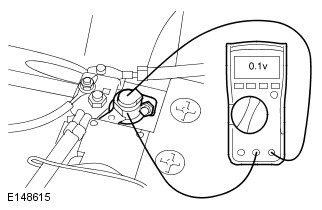
PINPOINT TEST A : VOLTAGE DROP ACROSS VEHICLE HARNESS AND BATTERY TERMINAL
|
|
|---|---|
| A1: GROUND CIRCUIT | |
| TEST CONDITIONS | DETAILS/RESULTS/ACTIONS |
|
NOTE:
This test checks for high resistance between the battery terminal and the battery clamp. |
|
|
1
Connect the multimeter across the battery negative terminal and the battery clamp as shown in picture (do not disconnect the battery at this stage). Set the multimeter to read Direct Current (DC) voltage.
|
|
 |
2
Start the engine, turn on the following:
|
|
|
Is reading equal to or below 0.1 volts?
Yes
No
Switch all electrical loads and engine off, return the vehicle to an ignition off condition. Disconnect the battery negative clamp, clean clamp and terminal then reconnect and repeat test GO toA1.
|
| A2: POWER CIRCUIT | |
|---|---|
| TEST CONDITIONS | DETAILS/RESULTS/ACTIONS |
|
NOTE:
This test checks for high resistance between the battery terminal and the battery clamp. |
|
|
1
Connect the multimeter across the battery positive terminal and the battery clamp as shown in picture (do not disconnect the battery at this stage). Set the multimeter to read DC voltage.
|
|
 |
2
Start the engine, turn on the following:
|
|
|
Is reading equal to or below 0.1 volts?
Yes
Complete Midtronics battery test procedure
No
Switch all electrical loads and engine off, return the vehicle to an ignition off condition. Disconnect the battery power clamp, clean clamp and terminal then reconnect and repeat test GO toA2.
|
The following steps must be completed to facilitate correct operation of the EXP-1080 JLR hand-held battery diagnostic tool during the battery test procedure
| CHECKS | ACTION |
|---|---|
| Battery fluid leakage, check for battery fluid leaks or damage to the battery casing |
NOTE:
If visible damage to the case is evident do not return battery under warranty. |
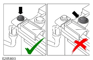
| Battery vent pipe routing | Check for routing, make sure there are no kinks |
| EXP-1080 fly lead, condition of clamps | Clean or replace as required |
| EXP-1080 fly lead connection | Confirm secure connection |
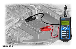
The Midtronics EXP-1080 JLR hand-held battery diagnostic tool is suitable for testing flooded and absorbed glass mat (AGM) type batteries including Primary and Secondary batteries.
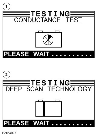
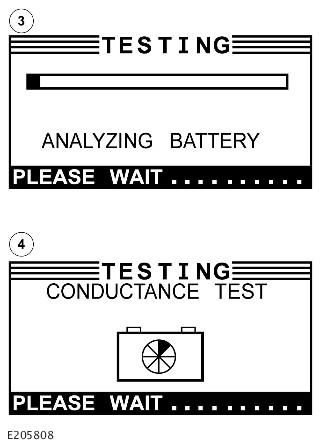
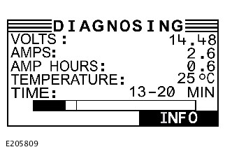
Using the Midtronics EXP-1080 JLR hand-held battery diagnostic tool, the following test procedure will confirm the serviceability of the battery (see Completing a Battery Test)
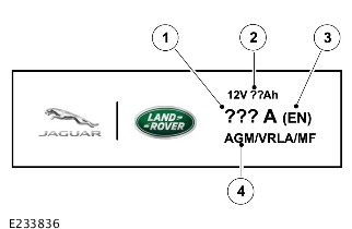
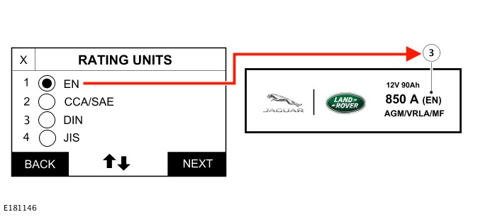
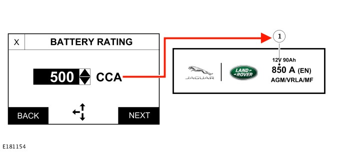
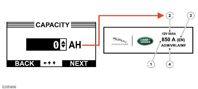
Battery Label Example
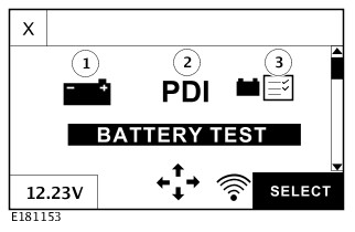
The Midtronics EXP-1080 JLR hand-held battery diagnostic tool has three types of battery test available to the technician to select:
Battery Test
- 1.The BATTERY TEST should be used on any battery that has started its warranty life cycle. The battery is in use and installed to a vehicle registered to an owner
Pre-Delivery Inspection (PDI) / Storage
- 2.The PDI / STORAGE test should be used on any battery that has not yet been entered into the warranty life cycle. The battery is installed to a NEW vehicle, but the vehicle has not yet been sold/registered to an owner
Battery Storage
- 3. This BATT. STORAGE test should be used on any battery that has not yet been entered into the warranty life cycle. The battery is not in use and is a Parts Stock battery and has not yet been installed to a vehicle
Completing a Battery Test
Battery Tester Results Table
If the vehicle is equipped with a flooded battery, make sure the replacement battery is a flooded battery of the same specification (cold cranking amperage (CCA), battery standard (EN/SAE) / amp hour rating (Ah)) as the original battery
Under no circumstances should you fit a flooded battery to a vehicle that originally had an AGM battery, unless formally instructed by Jaguar/Land Rover
If the vehicle is equipped with an absorbed glass mat (AGM) battery, make sure the replacement battery is a AGM battery of the same specification (cold cranking amperage (CCA), battery standard (EN/SAE) / amp hour rating (Ah)) as the original battery, unless formally instructed by Jaguar/Land Rover
For a list of Diagnostic Trouble Codes (DTCs) that could be set on this vehicle, please refer to Section 100-00.
2017.0 RANGE ROVER SPORT (LW), 414-01
BATTERY, MOUNTING AND CABLES
BATTERY DIAGNOSTICS - 12 VOLT MIDTRONICS GRX-3080 JLR DIAGNOSTIC BATTERY CHARGER (G2156742)
For a detailed description of the battery system and operation, refer to the relevant Description and Operation section of the workshop manual REFER to:Battery and Cables (414-01 Battery, Mounting and Cables, Description and Operation).
Diagnosis by substitution from a donor vehicle is NOT acceptable. Substitution of control modules does not guarantee confirmation of a fault and may also cause additional faults in the vehicle being checked and/or the donor vehicle.
-
Generic scan tools may not read the codes listed, or may read only five digit codes. Match the five digits from the scan tool to the first five digits of the seven digit code listed to identify the fault (the last two digits give additional information read by the manufacturer-approved diagnostic system).
-
When performing voltage or resistance tests, always use a digital multimeter that has the resolution ability to view 3 decimal places. For example, on the 2 volts range can measure 1mV or 2 K Ohm range can measure 1 Ohm. When testing resistance always take the resistance of the digital multimeter leads into account.
-
Check and rectify basic faults before beginning diagnostic routines involving pinpoint tests.
-
If Diagnostic Trouble Code(s) (DTC)s are recorded and, after performing the pinpoint tests, a fault is not present, an intermittent concern may be the cause. Always check for loose connections and corroded terminals.
- Verify the customer concern
- Visually inspect for obvious signs of mechanical or electrical damage
Visual Inspection
| MECHANICAL | ELECTRICAL |
|---|---|
|
|
- If an obvious cause for an observed or reported concern is found, correct the cause (if possible) before proceeding to the next step
- If the cause is not visually evident check for Diagnostic Trouble Codes (DTCs) and refer to the DTC Index
- Check JLR claims submission system for open campaigns. Refer to the corresponding bulletins and SSMs which may be valid for the specific customer complaint and complete the recommendations as required.
The following steps must be completed to facilitate correct operation of the GRX-3080 JLR diagnostic battery charger during the battery test procedure
| CHECKS | ACTION |
|---|---|
| Battery fluid leakage, check for battery fluid leaks or damage to the battery casing |
NOTE:
If visible damage to the case is evident do not return battery under warranty. |
| Battery vent pipe routing | Check for routing, make sure there are no kinks |
| GRX-3080 fly lead, condition of clamps | Clean or replace as required |
| GRX-3080 fly lead connection | Confirm secure connection |
The GRX-3080 JLR diagnostic battery charger is suitable for testing flooded and absorbed glass mat (AGM) type batteries including Primary and Secondary batteries
Using the GRX-3080 JLR diagnostic battery charger, the following test procedure will confirm the serviceability of the battery (see Completing a Battery Test)
Battery Label Example
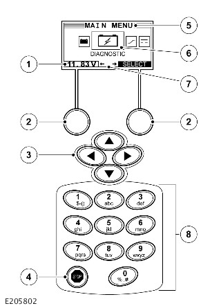
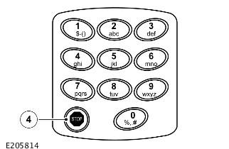
The GRX-3080 JLR diagnostic battery charger has an integrated display and keypad, the display guides the user through on-screen navigation aids, directions and messages. The illustration (below) shows how the elements on the screen relate to the keypad and details the functions of the various keys:
Before performing any battery diagnostic on a vehicle, make sure the ignition is OFF and the vehicle is powered down, with the modules entering 'sleep mode' before commencing and with the hazard switch illumination extinguished
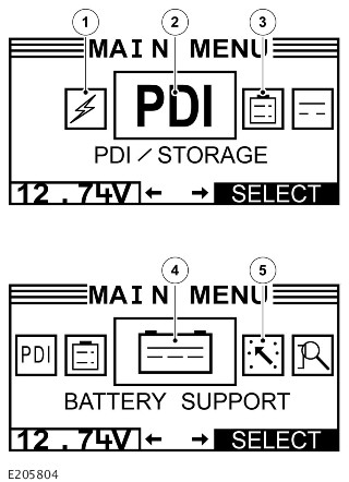
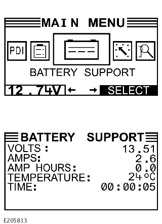
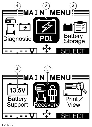
The Midtronics GRX-3080 JLR diagnostic battery charger has three types of battery test (Diagnostic Charging, Pre-Delivery Inspection (PDI) / Storage and Battery Storage), one battery support function (Battery Support Power Supply) and one manual charging option available (Recovery Charging) for the technician to select:
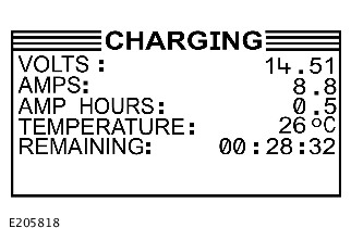
DIAGNOSTIC CHARGING
- 1. The DIAGNOSTIC CHARGING test needs to be used on any battery that has started its warranty life cycle. The battery is in use and installed to a vehicle registered to an owner. The GRX-3080 JLR diagnostic battery charger will determine the internal condition of a battery before attempting to apply a charge to it. If required, it will then charge and assess the battery until the battery condition is established and a test result is given
PDI / STORAGE
- 2. The PDI / STORAGE test needs to be used on any battery that has not yet been entered into the warranty life cycle. The battery is installed to a NEW vehicle, but the vehicle has not yet been sold/registered to an owner. The GRX-3080 JLR diagnostic battery charger will determine the internal condition of a battery before attempting to apply a charge to it. If required, it will then charge and assess the battery until the battery condition is established and a test result is given
BATTERY STORAGE
- 3. The BATT. STORAGE test should be used on any battery that has not yet been entered into the warranty life cycle. The battery is not in use and is a Parts Stock battery and has not yet been installed to a vehicle. The GRX-3080 JLR diagnostic battery charger will determine the internal condition of a battery before attempting to apply a charge to it. If required, it will then charge and assess the battery until the battery condition is established and a test result is given
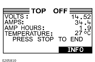
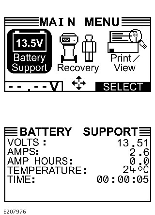
BATTERY SUPPORT Power Supply
- 4. The BATTERY SUPPORT Power Supply function needs to be used whenever the vehicle comes in to the workshop for regular maintenance or vehicle module updates. Updating modules can take up to several hours and during that period a lot of current will be depleted from the battery. To support the battery during this process use the BATTERY SUPPORT function. When working on a vehicle, it is recommended that the GRX-3080 is connected and switched to the BATTERY SUPPORT function to make sure that, when the work is completed, the battery’s state of charge is maintained at a healthy level
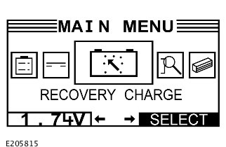
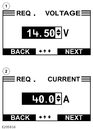
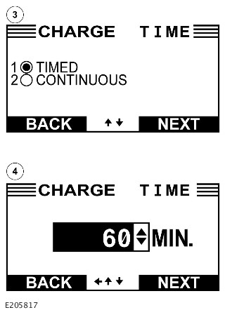
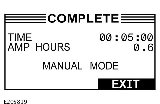
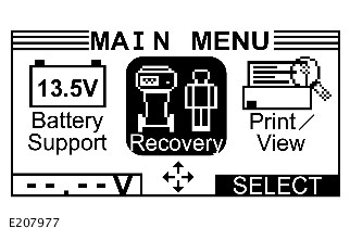
RECOVERY CHARGING
- 5. The RECOVERY CHARGING mode should only be used when the battery voltage is below nine volts. The current should be set to 50 amps for a flooded battery or 40 amps for an AGM battery. The timer for the duration of the RECOVERY CHARGING cycle should be set for one hour. set RECOVERY CHARGING is complete, the DIAGNOSTIC CHARGING (see above) mode may be used to assess the battery
Completing a Battery Test
Battery Tester Results Table
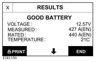
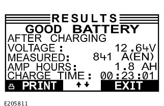
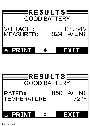
| RESULTS | ACTION |
|---|---|
| GOOD BATTERY |
|
| REPLACE BATTERY |
NOTE:
A 'REPLACE BATTERY' result may also mean a poor connection between the battery cables on the vehicle and the battery. Check connections and rectify as required
|
| FROZEN BATTERY |
|
| UNABLE TO DO TEST |
|
If the vehicle is equipped with a flooded battery, make sure the replacement battery is a flooded battery of the same specification (cold cranking amperage (CCA), battery standard (EN/SAE) / amp hour rating (Ah)) as the original battery
Under no circumstances should you fit a flooded battery to a vehicle that originally had an AGM battery, unless formally instructed by Jaguar/Land Rover
If the vehicle is equipped with an absorbed glass mat (AGM) battery, make sure the replacement battery is a AGM battery of the same specification (cold cranking amperage (CCA), battery standard (EN/SAE) / amp hour rating (Ah)) as the original battery, unless formally instructed by Jaguar/Land Rover
For a list of Diagnostic Trouble Codes (DTCs) that could be set on this vehicle, please refer to Section 100-00
2017.0 RANGE ROVER SPORT (LW), 414-01
BATTERY, MOUNTING AND CABLES
BATTERY DIAGNOSTICS - 12 VOLT MIDTRONICS GR8-1180 JLR DIAGNOSTIC BATTERY CHARGER (G2156743)
For a detailed description of the battery system and operation, refer to the relevant Description and Operation section of the workshop manual REFER to:Battery and Cables (414-01 Battery, Mounting and Cables, Description and Operation).
Diagnosis by substitution from a donor vehicle is NOT acceptable. Substitution of control modules does not guarantee confirmation of a fault and may also cause additional faults in the vehicle being checked and/or the donor vehicle.
-
Generic scan tools may not read the codes listed, or may read only five digit codes. Match the five digits from the scan tool to the first five digits of the seven digit code listed to identify the fault (the last two digits give additional information read by the manufacturer-approved diagnostic system).
-
When performing voltage or resistance tests, always use a digital multimeter that has the resolution ability to view 3 decimal places. For example, on the 2 volts range can measure 1mV or 2 K Ohm range can measure 1 Ohm. When testing resistance always take the resistance of the digital multimeter leads into account.
-
Check and rectify basic faults before beginning diagnostic routines involving pinpoint tests.
-
If Diagnostic Trouble Code(s) (DTC)s are recorded and, after performing the pinpoint tests, a fault is not present, an intermittent concern may be the cause. Always check for loose connections and corroded terminals.
- Verify the customer concern
- Visually inspect for obvious signs of mechanical or electrical damage
Visual Inspection
| MECHANICAL | ELECTRICAL |
|---|---|
|
|
- If an obvious cause for an observed or reported concern is found, correct the cause (if possible) before proceeding to the next step
- If the cause is not visually evident check for Diagnostic Trouble Codes (DTCs) and refer to the DTC Index
- Check JLR claims submission system for open campaigns. Refer to the corresponding bulletins and SSMs which may be valid for the specific customer complaint and complete the recommendations as required.
The following steps must be completed to facilitate correct operation of the GR8-1180 JLR diagnostic battery charger during the battery test procedure
| CHECKS | ACTION |
|---|---|
| Battery fluid leakage, check for battery fluid leaks or damage to the battery casing |
NOTE:
If visible damage to the case is evident do not return battery under warranty. |
| Battery vent pipe routing | Check for routing, make sure there are no kinks |
| GR8-1180 fly lead, condition of clamps | Clean or replace as required |
| GR8-1180 fly lead connection | Confirm secure connection |
The GR8-1180 JLR diagnostic battery charger is suitable for testing flooded and absorbed glass mat (AGM) type batteries including Primary and Secondary batteries
Using the GR8-1180 JLR diagnostic battery charger, the following test procedure will confirm the serviceability of the battery (see Completing a Battery Test)
Battery Label Example
The GR8-1180 JLR diagnostic battery charger has an integrated display and keypad, the display guides the user through on-screen navigation aids, directions and messages. The illustration (below) shows how the elements on the screen relate to the keypad and details the functions of the various keys:
Before performing any battery diagnostic on a vehicle, make sure the ignition is OFF and the vehicle is powered down, with the modules entering 'sleep mode' before commencing and with the hazard switch illumination extinguished
The Midtronics GR8-1180 JLR diagnostic battery charger has three types of battery test (Diagnostic Charging, Pre-Delivery Inspection (PDI) / Storage and Battery Storage), one battery support function (Battery Support Power Supply) and one manual charging option available (Recovery Charging) for the technician to select:
DIAGNOSTIC CHARGING
- 1. The DIAGNOSTIC CHARGING test needs to be used on any battery that has started its warranty life cycle. The battery is in use and installed to a vehicle registered to an owner. The GR8-1180 JLR diagnostic battery charger will determine the internal condition of a battery before attempting to apply a charge to it. If required, it will then charge and assess the battery until the battery condition is established and a test result is given
PDI/ STORAGE
- 2. The PDI / STORAGE test needs to be used on any battery that has not yet been entered into the warranty life cycle. The battery is installed to a NEW vehicle, but the vehicle has not yet been sold/registered to an owner. The GR8-1180 JLR diagnostic battery charger will determine the internal condition of a battery before attempting to apply a charge to it. If required, it will then charge and assess the battery until the battery condition is established and a test result is given
BATTERY STORAGE
- 3. The BATT. STORAGE test should be used on any battery that has not yet been entered into the warranty life cycle. The battery is not in use and is a Parts Stock battery and has not yet been installed to a vehicle. The GR8-1180 JLR diagnostic battery charger will determine the internal condition of a battery before attempting to apply a charge to it. If required, it will then charge and assess the battery until the battery condition is established and a test result is given
BATTERY SUPPORT Power Supply
- 4. The BATTERY SUPPORT Power Supply function needs to be used whenever the vehicle comes in to the workshop for regular maintenance or vehicle module updates. Updating modules can take up to several hours and during that period a lot of current will be depleted from the battery. To support the battery during this process use the BATTERY SUPPORT function. When working on a vehicle, it is recommended that the GR8-1180 JLR diagnostic battery charger is connected and switched to the BATTERY SUPPORT function to make sure that, when the work is completed, the battery’s state of charge is maintained at a healthy level
RECOVERY CHARGING
- 5. The RECOVERY CHARGING mode should only be used when the battery voltage is below nine volts. The current should be set to 50 amps for a flooded battery or 40 amps for an AGM battery. The timer for the duration of the RECOVERY CHARGING cycle should be set for one hour. When RECOVERY CHARGING is complete, the DIAGNOSTIC CHARGING (see above) mode may be used to assess the battery
Completing a Battery Test
Battery Tester Results Table
| RESULTS | ACTION |
|---|---|
| GOOD BATTERY |
|
| REPLACE BATTERY |
NOTE:
A 'REPLACE BATTERY' result may also mean a poor connection between the battery cables on the vehicle and the battery. Check connections and rectify as required
|
| FROZEN BATTERY |
|
| UNABLE TO DO TEST |
|
If the vehicle is equipped with a flooded battery, make sure the replacement battery is a flooded battery of the same specification (cold cranking amperage (CCA), battery standard (EN/SAE) / amp hour rating (Ah)) as the original battery
Under no circumstances should you fit a flooded battery to a vehicle that originally had an AGM battery, unless formally instructed by Jaguar/Land Rover
If the vehicle is equipped with an absorbed glass mat (AGM) battery, make sure the replacement battery is a AGM battery of the same specification (cold cranking amperage (CCA), battery standard (EN/SAE) / amp hour rating (Ah)) as the original battery, unless formally instructed by Jaguar/Land Rover
For a list of Diagnostic Trouble Codes (DTCs) that could be set on this vehicle, please refer to Section 100-00
BATTERY, MOUNTING AND CABLES
LOW BATTERY DIAGNOSTICS (G2339982)
For a detailed description of the Charging System, refer to the relevant Description and Operation section in the workshop manual.
Diagnosis by substitution from a donor vehicle is NOT acceptable. Substitution of control modules does not guarantee confirmation of a fault, and may also cause additional faults in the vehicle being tested and/or the donor vehicle.
Preparation - Only on vehicles, installed with a Secure Tracker feature
-
The 'Service Mode' feature is not available on North American Specification (NAS) market vehicles.
-
Before disconnecting power to the Telematic Control Unit Module (TCU) the vehicle owner must place the TCU into 'Service Mode'. The 'Service Mode' disables all alert triggers, except movement alert.
-
This must be done for example when disconnecting the startup battery to do maintenance repairs.
-
For security purposes 'Service Mode' is the sole responsibility of the vehicle owner as it requires a Personal Identification Number (PIN) code that has been defined by the owner.
The TCU 'Service Mode' can be activated in the following ways:
- Through the Call Center - The owner calls the Telematics Service Provider (TSP) and requests to set the vehicle into 'Service Mode'.
- Through the 'InControl© Remote' mobile phone application - The owner enables the 'Service Mode'.
- Through the InControl© website - The owner enables the 'Service Mode'.
-
If the TCU is not set into 'Service Mode', then communication to and from the TCU may be lost, which may prevent the vehicle starting.
-
Failure to do so may result in any warranty claim being rejected.
If the disconnection procedure is not performed, the system will send a theft alert to the following:
- The owner, through the InControl© Remote mobile phone application.
- The Telematics Service Provider (TSP).
Then the system will enter 'Theft Notification' or 'Stolen Vehicle Tracking' mode during which time the charge in the TCU battery would be used. The emergency services may be falsely alerted that the vehicle has been stolen.
When the startup battery is disconnected for a period of time, the vehicle owner can define the time it is to be disconnected for. If the time is exceeded, the vehicle owner must re-activate the 'Service Mode'. To re-activate the 'Service Mode' the vehicle owner is required to use 'InControl© Remote' mobile phone application.
-
If a control module or a component is not to specification and the vehicle remains under manufacturer warranty, refer to the Warranty Policy and Procedures manual, or determine if any prior approval program is in operation, prior to the installation of a new module/component.
-
When performing voltage or resistance tests, always use a digital multimeter accurate to three decimal places, and with an up-to-date calibration certificate. When testing resistance always take the resistance of the digital multimeter leads into account.
-
Check and rectify basic faults before beginning diagnostic routines involving pinpoint tests.
- Verify the customer concern
- Visually inspect for obvious signs of damage and system integrity
Visual Inspection
| MECHANICAL | ELECTRICAL |
|---|---|
|
|
- If an obvious cause for an observed or reported concern is found, correct the cause (if possible) before proceeding to the next step
- If the cause is not visually evident, verify the symptom and refer to the Symptom Chart, alternatively check for Diagnostic Trouble Code(s) (DTC) and refer to the DTC Index
- Check JLR Claims Submission System for open campaigns. Refer to the corresponding bulletins and SSMs which may be valid for the specific customer complaint and complete the recommendations as required
| SYMPTOM | POSSIBLE CAUSES | ACTION |
|---|---|---|
| Low battery warning indicator illuminated |
|
|
The following questions should be put to the customer on arrival at the service centre. The data gathered should be recorded and retained as the information may be needed to be added to a Technical Assistance (TA) request for engineering evaluation if the vehicle's battery system fault. Select and record the appropriate response to each of the questions listed below:
- 1) Before the low battery was noted, had the vehicle doors been opened and closed multiple times while the vehicle had been unlocked and the engine off for over an hour or more (this may happen during loading and unloading of luggage, equipment, etc)? YES / NO
- 2) Has the Stop/Start function consistently been inhibited during the drive cycle? YES / NO
- 3) How often is the vehicle used? Daily / Every Other Day / Weekly / Less Than One Day A Week
- 4) What is the average length of journeys made? Less Than 10 Miles / Between 10 and 50 Miles / Over 50 Miles
- 5) How many engine starts (not including Stop/Start activations) does the vehicle typically undergo in one day? Less Than 5 / Greater Than 5
- 6) If applicable, has the rear tailgate failed to extend fully at any point leading up to the low battery issue? YES (give details) / NO
- 7) Are any accessories installed to the vehicle (either through the OBD port or hard wired ie: such as dash cameras)? YES (give details) / NO
- 8) Note any other information - ask the customer if they have any additional comments they feel may be relevant to the factors leading up to the fault
|
PINPOINT TEST A : INITIAL CONSULTATION - IMMEDIATE VEHICLE HISTORY PRIOR TO LOW BATTERY WARNINGS
|
|
|---|---|
| A1: HAS CUSTOMER BEHAVIOR CAUSED THE LOW BATTERY WARNING? | |
| TEST CONDITIONS | DETAILS/RESULTS/ACTIONS |
|
1
Gather information from the customer about recent usage. Specifically, ask the customer the following:
|
|
|
|
Before the low battery warning appeared, had the vehicle doors been opened and closed multiple times while the vehicle had been unlocked and the engine off for over an hour or more (this may happen during loading and unloading of luggage, equipment, etc)?
Yes
No
GO to Pinpoint TestB.
|
| A2: QUIESCENT DRAIN TEST (1) | |
|---|---|
| TEST CONDITIONS | DETAILS/RESULTS/ACTIONS |
|
1
Refer to the relevant section of the workshop manual and test the battery quiescent drain REFER to:Quiescent Drain (414-00 Battery and Charging System - General Information, Description and Operation).
|
|
|
|
Has the quiescent current drain test been passed? (ie: the vehicle's typical battery drain values are less than 30mA)
Yes
To confirm the state of battery health, refer to the appropriate Midtronics Battery Diagnostics/Battery Charger procedures and follow the on-screen instructions REFER to:(414-01 Battery, Mounting and Cables)
Battery Diagnostics - 12 Volt Midtronics EXP-1080 JLR Hand-Held Battery Diagnostic Tool (Diagnosis and Testing),
Battery Diagnostics - 12 Volt Midtronics GRX-3080 JLR Diagnostic Battery Charger (Diagnosis and Testing),
Battery Diagnostics - 12 Volt Midtronics GR8-1180 JLR Diagnostic Battery Charger (Diagnosis and Testing).
When the Midtronics procedures have been successfully completed, the vehicle may be returned to the customer. Advise customer that pattern of usage has caused low battery warning and how to avoid reoccurrenceNo
GO to Pinpoint TestB.
|
| B2: BATTERY TESTING | |
|---|---|
| TEST CONDITIONS | DETAILS/RESULTS/ACTIONS |
|
1
To confirm the state of battery health, refer to the appropriate Midtronics Battery Diagnostics/Battery Charger procedures and follow the on-screen instructions REFER to:(414-01 Battery, Mounting and Cables)
Battery Diagnostics - 12 Volt Midtronics EXP-1080 JLR Hand-Held Battery Diagnostic Tool (Diagnosis and Testing),
Battery Diagnostics - 12 Volt Midtronics GRX-3080 JLR Diagnostic Battery Charger (Diagnosis and Testing),
Battery Diagnostics - 12 Volt Midtronics GR8-1180 JLR Diagnostic Battery Charger (Diagnosis and Testing).
|
|
|
|
Is the battery test passed?
Yes
Raise a TA request to log service actions. Using the Jaguar Land Rover approved diagnostic equipment, reset the BMS and return the vehicle to the customer
No
If battery diagnostics suggest a battery replacement is warranted, replace battery. Using the Jaguar Land Rover approved diagnostic equipment, reset the BMS and return the vehicle to the customer. If the battery in not replaced, raise a TA to log service actions. Using the Jaguar Land Rover approved diagnostic equipment, reset the BMS and return the vehicle to the customer
|
| B3: QUIESCENT DRAIN TEST (2) | |
|---|---|
| TEST CONDITIONS | DETAILS/RESULTS/ACTIONS |
|
1
Refer to the relevant section of the workshop manual and test the battery quiescent drain REFER to:Quiescent Drain (414-00 Battery and Charging System - General Information, Description and Operation).
|
|
|
|
Has the quiescent current drain test been passed? (ie: the vehicle's typical battery drain values are less than 30mA)
Yes
No
|
| B5: BATTERY SUPPORT/CONSULT LOGS | |
|---|---|
| TEST CONDITIONS | DETAILS/RESULTS/ACTIONS |
|
1
Attach a Jaguar Land Rover approved battery support unit to prevent the battery going flat
|
|
|
2
Raise a TA request and add the information gathered from the customer questionnaire completed when the vehicle was initially brought in to the service centre
|
|
|
3
Contact the Technical Assistance team to request access to a CAN logging device with breakout harness (to facilitate access to vehicle CAN logs). Download CAN logs as required
|
|
|
4
Consult with Technical Assistance team and examine the CAN logs to ascertain module/systems causing battery drain and rectify as required
|
|
|
5
To confirm the state of battery health, refer to the appropriate Midtronics Battery Diagnostics/Battery Charger procedures and follow the on-screen instructions REFER to:(414-01 Battery, Mounting and Cables)
Battery Diagnostics - 12 Volt Midtronics EXP-1080 JLR Hand-Held Battery Diagnostic Tool (Diagnosis and Testing),
Battery Diagnostics - 12 Volt Midtronics GRX-3080 JLR Diagnostic Battery Charger (Diagnosis and Testing),
Battery Diagnostics - 12 Volt Midtronics GR8-1180 JLR Diagnostic Battery Charger (Diagnosis and Testing).
|
|
|
|
Is the battery test passed?
Yes
Using the Jaguar Land Rover approved diagnostic equipment, reset the BMS and return the vehicle to the customer
No
If battery diagnostics suggest a battery replacement is required, replace battery. Using the Jaguar Land Rover approved diagnostic equipment, reset the BMS and return the vehicle to the customer
|
In cases where the customer reports a low battery warning on a vehicle indicating a drain on the battery (and where the battery drain has NOT been detected by the quiescent drain test REFER to:Quiescent Drain (414-00 Battery and Charging System - General Information, Description and Operation).), a more thorough investigation may be required to identify the root cause of the battery drain
Print out the test plan and user guide form (below) and follow the battery drain investigation procedures. There are seven sets of tests, each set comprises three task lists. Not all seven sets of tests needs to be completed on every vehicle, this is a list of actions designed to prompt a vehicle failure. If a failure is detected, do not continue with the remaining sets, connect a Jaguar Land Rover approved battery support unit to prevent the battery going flat and raise a TA request immediately. If the vehicle is only available for a reduced amount of time, complete as many sets as possible before the return of the vehicle
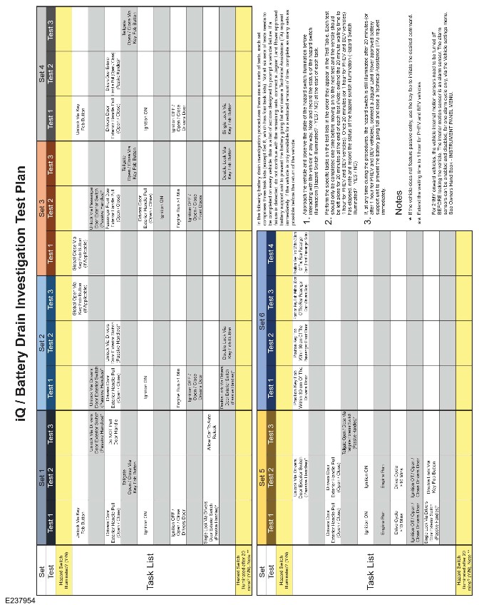
For a list of DTC that could be set on this vehicle, please refer to Section 100-00. REFER to:Diagnostic Trouble Code Index - DTC: Gateway Module (GWM) (100-00 General Information, Description and Operation).
2017.0 RANGE ROVER SPORT (LW), 414-01
BATTERY, MOUNTING AND CABLES
FLAT BATTERY DIAGNOSTICS (G2626607)
For a detailed description of the Charging System, refer to the relevant Description and Operation section in the workshop manual.
Diagnosis by substitution from a donor vehicle is NOT acceptable. Substitution of control modules does not guarantee confirmation of a fault, and may also cause additional faults in the vehicle being tested and/or the donor vehicle.
Preparation - Only on vehicles, installed with a Secure Tracker feature
-
The 'Service Mode' feature is not available on North American Specification (NAS) market vehicles.
-
Before disconnecting power to the Telematic Control Unit Module (TCU) the vehicle owner must place the TCU into 'Service Mode'. The 'Service Mode' disables all alert triggers, except movement alert.
-
This must be done for example when disconnecting the startup battery to do maintenance repairs.
-
For security purposes 'Service Mode' is the sole responsibility of the vehicle owner as it requires a Personal Identification Number (PIN) code that has been defined by the owner.
The TCU 'Service Mode' can be activated in the following ways:
- Through the Call Center - The owner calls the Telematics Service Provider (TSP) and requests to set the vehicle into 'Service Mode'.
- Through the 'InControl© Remote' mobile phone application - The owner enables the 'Service Mode'.
- Through the InControl© website - The owner enables the 'Service Mode'.
-
If the TCU is not set into 'Service Mode', then communication to and from the TCU may be lost, which may prevent the vehicle starting.
-
Failure to do so may result in any warranty claim being rejected.
If the disconnection procedure is not performed, the system will send a theft alert to the following:
- The owner, through the InControl© Remote mobile phone application.
- The Telematics Service Provider (TSP).
Then the system will enter 'Theft Notification' or 'Stolen Vehicle Tracking' mode during which time the charge in the TCU battery would be used. The emergency services may be falsely alerted that the vehicle has been stolen.
When the startup battery is disconnected for a period of time, the vehicle owner can define the time it is to be disconnected for. If the time is exceeded, the vehicle owner must re-activate the 'Service Mode'. To re-activate the 'Service Mode' the vehicle owner is required to use 'InControl© Remote' mobile phone application.
-
If a control module or a component is at fault or may be at fault and the vehicle remains under manufacturer warranty, refer to the Warranty Policy and Procedures manual, or determine if any prior approval program is in operation, prior to the installation of a new module/component.
-
When performing voltage or resistance tests, always use a digital multimeter accurate to three decimal places, and with an up-to-date calibration certificate. When testing resistance always take the resistance of the digital multimeter leads into account.
-
Check and rectify basic faults before beginning diagnostic routines involving pinpoint tests.
- Verify the customer concern
- Visually inspect for obvious signs of damage and system integrity
Visual Inspection
| MECHANICAL | ELECTRICAL |
|---|---|
|
|
- If an obvious cause for an observed or reported concern is found, correct the cause (if possible) before proceeding to the next step
- If the cause is not visually evident, verify the symptom and refer to the Symptom Chart, alternatively check for Diagnostic Trouble Code(s) (DTC) and refer to the DTC Index
- Check JLR claims submission system for open campaigns. Refer to the corresponding bulletins and SSMs which may be valid for the specific customer complaint and complete the recommendations as required.
| SYMPTOM | POSSIBLE CAUSES | ACTION |
|---|---|---|
| Customer complains of flat battery |
|
|
The following questions should be put to the customer on arrival at the service centre. The data gathered should be recorded and retained as the information may be needed to be added to a Technical Assistance (TA) request for engineering evaluation if the vehicle's battery system fault. Select and record the appropriate response to each of the questions listed below:
- 1) Has the battery gone flat within the past 36 hours? YES / NO
- 2) How long has the vehicle stood prior to discovering the flat battery? Less Than 3 Days / Between 3 And 7 Days / Between 7 And 14 Days/ Longer Than 14 Days
- 3) Before the flat battery was noted, had the vehicle doors been opened and closed multiple times while the vehicle had been unlocked and the engine off for over an hour or more (this may happen during loading and unloading of luggage, equipment, etc)? YES / NO
- 4) How did you gain access to the vehicle? Through Key Fob / Use of Manual Key / Through Handle Pull
- 5) Have you required assistance for battery issues previously? YES (give details) / NO
- 6) Has the Stop/Start function consistently been inhibited during the drive cycle? YES / NO
- 7) How often is the vehicle used? Daily / Every Other Day / Weekly / Less Than One Use A Week
- 8) What is the average length of journeys made? Less Than 10 Miles / Between 10 and 50 Miles / Over 50 Miles
- 9) How many engine starts (not including Stop/Start activations) does the vehicle typically undergo in one day? Less Than 5 / Greater Than 5
- 10) Have any instrument pack warnings been observed leading up to the flat battery issue? YES (give details) / NO
- 11) If applicable, has the rear tailgate failed to extend fully at any point leading up to the flat battery issue? YES (give details) / NO
- 12) Are any accessories installed to the vehicle (either through the OBD port or hard wired ie: such as dash cameras)? YES (give details) / NO
- 13) Note any other information - ask the customer if they have any additional comments they feel may be relevant to the factors leading up to the fault
|
PINPOINT TEST A :
|
|
|---|---|
| A1: RECORD BATTERY VOLTAGE AND ATTEMPT ENGINE START | |
| TEST CONDITIONS | DETAILS/RESULTS/ACTIONS |
|
1
If the vehicle has been recovered to the retailer, then, using a Digital Multi Meter (DMM), record the battery open circuit voltage and make a note of the voltage
|
|
|
2
Attempt to start the engine
|
|
|
|
Does the engine start unaided?
Yes
No
Complete the RECOVERY CHARGING process using a manufacturer approved battery charger. If either a Midtronics GRX-3080 or GR8-1180 Diagnostic Battery Charger is available, then follow the Recovery Charging procedures as described elsewhere in this manual REFER to:(414-01 Battery, Mounting and Cables)
Battery Diagnostics - 12 Volt Midtronics GRX-3080 JLR Diagnostic Battery Charger (Diagnosis and Testing),
Battery Diagnostics - 12 Volt Midtronics GR8-1180 JLR Diagnostic Battery Charger (Diagnosis and Testing).
If no suitable tools (ie: with access to Recovery Charging procedures) are available, then charge the battery for 1 hour. When charging/recovery charging has been completed, then GO toA2. |
| A2: POWER SUPPLY SYSTEMS TEST | |
|---|---|
| TEST CONDITIONS | DETAILS/RESULTS/ACTIONS |
|
1
Using the manufacturer approved diagnostic system (SDD), connect the diagnostic tool to the vehicle. If SDD is not available, then proceed to the next step (A3)
|
|
|
2
Complete the Power Supply Systems test (72020). Using SDD, select Electrical - Warning Lights - Power Supply System Test
|
|
|
|
If SDD has been used, has the vehicle passed the power supply system test?
Yes
No
Follow the on-screen instructions to identify the root cause of the power supply system fault and rectify as required, then GO toA3.
|
| A3: BATTERY TESTING | |
|---|---|
| TEST CONDITIONS | DETAILS/RESULTS/ACTIONS |
|
1
To confirm the state of battery health, refer to the appropriate Midtronics Battery Diagnostics/Battery Charger procedures and follow the on-screen instructions REFER to:(414-01 Battery, Mounting and Cables)
Battery Diagnostics - 12 Volt Midtronics EXP-1080 JLR Hand-Held Battery Diagnostic Tool (Diagnosis and Testing),
Battery Diagnostics - 12 Volt Midtronics GRX-3080 JLR Diagnostic Battery Charger (Diagnosis and Testing),
Battery Diagnostics - 12 Volt Midtronics GR8-1180 JLR Diagnostic Battery Charger (Diagnosis and Testing).
|
|
|
|
After completion of the battery testing procedures as above, do the results indicate "Good Battery"?
Yes
GO to Pinpoint TestB.
No
If using the Midtronics EXP-1080 JLR Hand-Held Battery Diagnostic Tool, the process flow may result in a "REPLACE BATTERY" decision. In this case, with reference to the relevant section of the workshop manual, replace the battery taking care to complete the battery replacement process in order to appropriately clear/reset the BMS, then GO to Pinpoint TestB.
|
| B2: QUIESCENT DRAIN TEST (QUIESCENT RELAY BOX - RELAY 1 AND 2 OPEN EVENT COUNTERS GREATER THAN OR EQUAL TO 1) | |
|---|---|
| TEST CONDITIONS | DETAILS/RESULTS/ACTIONS |
|
1
Refer to the relevant section of the workshop manual and test the battery quiescent drain REFER to:Quiescent Drain (414-00 Battery and Charging System - General Information, Description and Operation).
|
|
|
|
Has the quiescent current drain test been passed? (ie: the vehicle's typical battery drain values are less than 30mA)
Yes
No
|
| B3: QUIESCENT DRAIN TEST (QUIESCENT RELAY BOX - RELAY 1 AND 2 OPEN EVENT COUNTERS LESS THAN 1) | |
|---|---|
| TEST CONDITIONS | DETAILS/RESULTS/ACTIONS |
|
1
Refer to the relevant section of the workshop manual and test the battery quiescent drain REFER to:Quiescent Drain (414-00 Battery and Charging System - General Information, Description and Operation).
|
|
|
|
Has the quiescent current drain test been passed? (ie: the vehicle's typical battery drain values are less than 30mA)
Yes
Using the manufacturer approved diagnostic system, check for related DTC and refer to the relevant DTC index for diagnosis and repairs as appropriate. When repairs (if required) have been completed, return the vehicle to the customer
No
|
| B5: RAISE /CONSULT LOGS | |
|---|---|
| TEST CONDITIONS | DETAILS/RESULTS/ACTIONS |
|
1
Raise a TA request and add the information gathered from the customer questionnaire completed when the vehicle was initially brought in to the service centre
|
|
|
|
Is the Hazard Warning light illuminated?
Yes
No
Module level quiescent suspected. Consult with Technical Assistance team to ascertain module/systems causing battery drain and rectify as required. Then, GO toB7.
|
| B6: HAZARD ILLUMINATION ON AND BATTERY DRAIN GREATER THAN 2 AMPS? | |
|---|---|
| TEST CONDITIONS | DETAILS/RESULTS/ACTIONS |
|
1
Using a manufacturer approved Picoscope or Digital Multi Meter (DMM), measure the battery drain
|
|
|
|
Is the battery drain greater than 2 amps?
Yes
Contact the Technical Assistance team to request access to a CAN logging device with breakout harness (to facilitate access to vehicle CAN logs). Download CAN logs as required. Consult with Technical Assistance team and examine the CAN logs to ascertain module/systems causing battery drain and rectify as required. Then, GO toB7.
No
Consult with Technical Assistance team to ascertain module/systems causing battery drain and rectify as required. Then, GO toB7.
|
| B7: FINAL BATTERY CHECKS | |
|---|---|
| TEST CONDITIONS | DETAILS/RESULTS/ACTIONS |
|
1
To confirm the state of battery health, refer to the appropriate Midtronics Battery Diagnostics/Battery Charger procedures and follow the on-screen instructions REFER to:(414-01 Battery, Mounting and Cables)
Battery Diagnostics - 12 Volt Midtronics EXP-1080 JLR Hand-Held Battery Diagnostic Tool (Diagnosis and Testing),
Battery Diagnostics - 12 Volt Midtronics GRX-3080 JLR Diagnostic Battery Charger (Diagnosis and Testing),
Battery Diagnostics - 12 Volt Midtronics GR8-1180 JLR Diagnostic Battery Charger (Diagnosis and Testing).
|
|
|
|
After completion of the battery testing procedures as above, do the results indicate "Good Battery"?
Yes
Return the vehicle to the customer
No
If using the Midtronics EXP-1080 JLR Hand-Held Battery Diagnostic Tool, the process flow may result in a "REPLACE BATTERY" decision. In this case, with reference to the relevant section of the workshop manual, replace the battery taking care to complete the battery replacement process in order to appropriately clear/reset the BMS, then return the vehicle to the customer
|
In cases where the customer reports a flat battery and where the battery drain has NOT been detected by the quiescent drain test REFER to:Quiescent Drain (414-00 Battery and Charging System - General Information, Description and Operation)., a more thorough investigation may be required to identify the root cause of the battery drain
Print out the test plan and user guide form (below) and follow the battery drain investigation procedures. There are seven sets of tests, each set comprises three task lists. Not all seven sets of tests needs to be completed on every vehicle, this is a list of actions designed to prompt a vehicle failure. If a failure is detected, do not continue with the remaining sets, connect a manufacturer approved battery support unit to prevent the battery going flat and raise a TA request immediately. If the vehicle is only available for a reduced amount of time, complete as many sets as possible before the return of the vehicle
For a list of DTC that could be set on this vehicle, please refer to Section 100-00. REFER to:Diagnostic Trouble Code Index - DTC: Body Control Module (BCM) (100-00 General Information, Description and Operation).
Repairs2017.0 RANGE ROVER SPORT (LW), 414-01
BATTERY, MOUNTING AND CABLES
STARTUP BATTERY - VEHICLES WITH: 5 SEATS (G2743757)
| Name | Quantity | Part Number |
|---|---|---|
| Startup Battery | 1 | LR094642 |
| Name | Quantity | Part Number | VIN range from |
|---|---|---|---|
| Startup Battery | 1 | LR093840 | GA000001 |
| Name | Quantity | Part Number |
|---|---|---|
| Startup Battery | 1 | LR104511 |
PUBLISHED: 13-JUL-2018
2017.0 RANGE ROVER SPORT (LW), 414-01
BATTERY, MOUNTING AND CABLES
BATTERY - VEHICLES WITHOUT: 7 SEATS (G1558977)
- 86.15.01
- STARTUP BATTERY - RENEW
- 2000 CC, INGENIUM DIESEL
- 0.40
- USED WITHINS
- 86.15.01
- STARTUP BATTERY - RENEW
- 2000 CC, SI4
- 0.40
- USED WITHINS
- 86.15.01
- STARTUP BATTERY - RENEW
- 3000 CC, AJ V6 (AJ126)
- 0.40
- USED WITHINS
- 86.15.01
- STARTUP BATTERY - RENEW
- 3000 CC, TDV6
- 0.40
- USED WITHINS
- 86.15.01
- STARTUP BATTERY - RENEW
- 4400 CC, TDV8
- 0.40
- USED WITHINS
- 86.15.01
- STARTUP BATTERY - RENEW
- 5000 CC, AJ V8
- 0.40
- USED WITHINS
GENERAL EQUIPMENT
| EQUIPMENT NAME |
|---|
| Jaguar Land Rover approved diagnostic equipment |
- This procedure contains some variation in the illustrations depending on the vehicle specification, but the essential information is always correct.
- This procedure contains illustrations showing certain components removed to provide extra clarity.
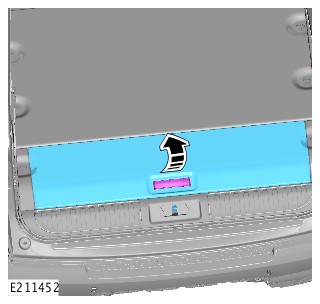
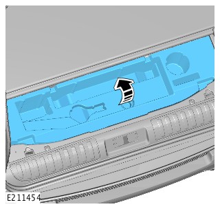
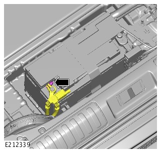
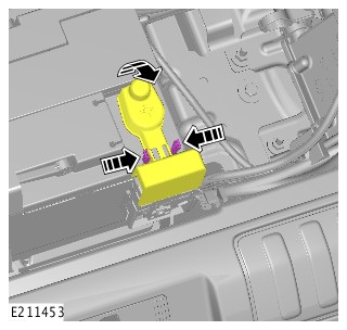
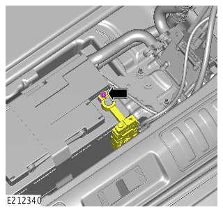
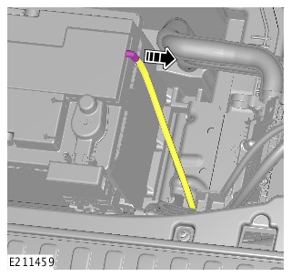
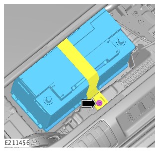
-
- Install the battery.
- Secure the battery with the fabric strap.
Torque: 9Nm
- Install the vent hose.
-
CAUTIONS:
-
Make sure the battery monitoring system (BMS) electrical connector is connected to the module, before installing the BMS on to the battery terminal.
-
Make sure the clamping lug on the BMS is below the top of the negative terminal post as shown.
Connect the startup battery positive cable.Torque: 6Nm -
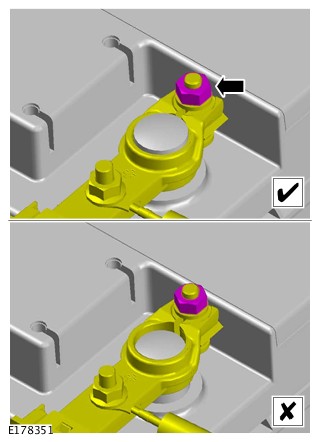
- Install the positive terminal cover.
- Connect the startup battery ground cable.
Torque: 6Nm
- Install the tool kit tray.
- Install the loadspace floor panel.
- Install the right loadspace trim panel.
- Complete the battery rest procedure using the approved Jaguar Land Rover diagnostic equipment.
2017.0 RANGE ROVER SPORT (LW), 414-01
BATTERY, MOUNTING AND CABLES
STARTUP BATTERY - VEHICLES WITH: 7 SEATS (G2798134)
| Name | Quantity | Part Number |
|---|---|---|
| Startup Battery | 1 | LR094642 |
| Name | Quantity | Part Number | VIN range from |
|---|---|---|---|
| Startup Battery | 1 | LR093840 | GA000001 |
| Name | Quantity | Part Number |
|---|---|---|
| Startup Battery | 1 | LR104511 |
PUBLISHED: 13-JUL-2018
2017.0 RANGE ROVER SPORT (LW), 414-01
BATTERY, MOUNTING AND CABLES
BATTERY - VEHICLES WITH: 7 SEATS (G1716321)
- 86.15.01
- STARTUP BATTERY - RENEW
- 2000 CC, INGENIUM DIESEL
- 0.40
- USED WITHINS
- 86.15.01
- STARTUP BATTERY - RENEW
- 2000 CC, SI4
- 0.40
- USED WITHINS
- 86.15.01
- STARTUP BATTERY - RENEW
- 3000 CC, AJ V6 (AJ126)
- 0.40
- USED WITHINS
- 86.15.01
- STARTUP BATTERY - RENEW
- 3000 CC, TDV6
- 0.40
- USED WITHINS
- 86.15.01
- STARTUP BATTERY - RENEW
- 4400 CC, TDV8
- 0.40
- USED WITHINS
- 86.15.01
- STARTUP BATTERY - RENEW
- 5000 CC, AJ V8
- 0.40
- USED WITHINS
-
Some variation in the illustrations may occur, but the essential information is always correct.
-
Removal steps in this procedure may contain installation details.
-
If a new battery is installed, the battery monitoring system (BMS) must be reset using Land Rover approved diagnostic equipment.
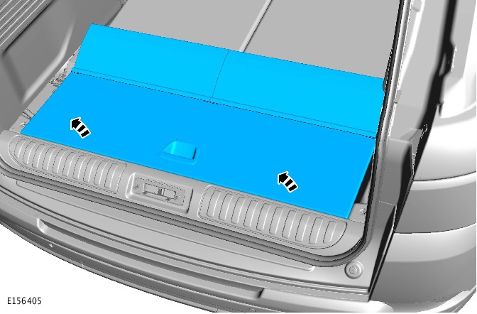
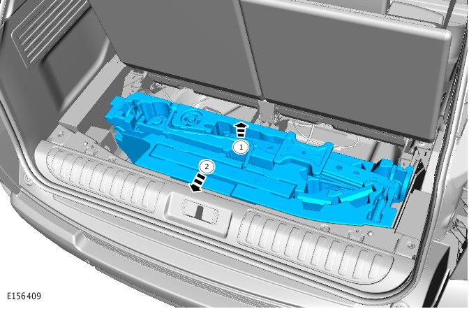
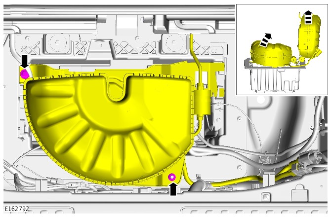
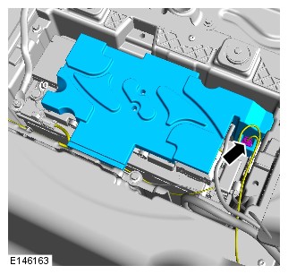
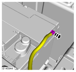
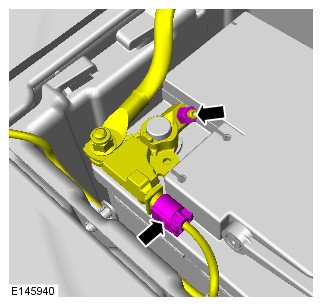
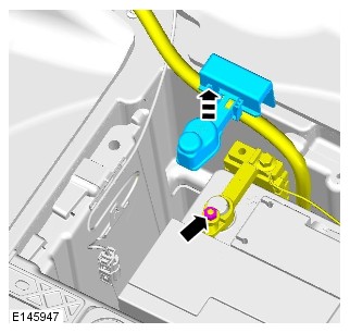
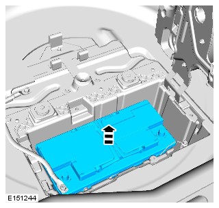
-
CAUTIONS:
-
Make sure that the air suspension compressor is located correctly in its mounting bracket.
-
Make sure that the battery monitoring system (BMS) module wiring harness does not get caught beneath the battery securing clamp.
-
Make sure that the battery is positioned fully outboard on the battery tray and that no harnesses or hoses are trapped.
-
Make sure that the component is correctly located on its mounting bracket. Lift the component by 10mm before lowering into position.
-
Make sure the battery monitoring system (BMS) electrical connector is connected to the module, before installing the BMS on to the battery terminal.
To install, reverse the removal procedure. -
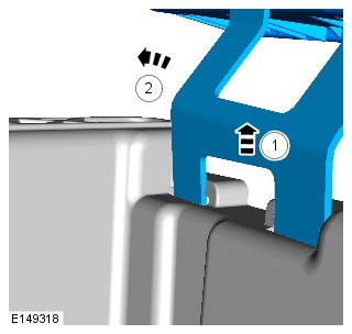
-
Using Land Rover approved diagnostic equipment, reset the battery monitoring system (BMS).NOTE:
This step is only necessary when installing a new battery.
2017.0 RANGE ROVER SPORT (LW), 414-01
BATTERY, MOUNTING AND CABLES
HYBRID ELECTRIC VEHICLE POWER DOWN/UP (G1661160)
- 01.01.30
- HIGH VOLTAGE BATTERY - DISCONNECT
- 3000 CC, TDV6, DIESEL, HEV
- 0.60
- USED WITHINS
SPECIAL TOOL(S)
JLR-415-009
Hybrid Electric Vehicle (HEV) Battery Isolator
JLR-415-042
Blanking plug
GENERAL EQUIPMENT
| EQUIPMENT NAME |
|---|
| Hybrid / Electric Vehicle Personal Protective Equipment (PPE) |
| Hybrid Electric Vehicle (HEV) break-out box - VM8105 |


-
This procedure must be carried out in the exact sequence shown. Failure to do so could result in serious personal injury.
-
It is the responsibility of the EVAP/EVSAP to make sure they comply with any local legislation regarding working with High Voltages (HV) within this procedure.
-
This procedure requires the use Class 0 Personal Protective Equipment (PPE), all persons involved in this procedure must have read and understood the PPE requirements as detailed in section 414-01B Electric Vehicle Safety Rules.
-
The approved Personal Protective Equipment (PPE) must be worn where indicated by the orange PPE icons within this procedure, all persons involved in this procedure must have read and understood section 100-00 About This Manual before continuing.
-
All PPE equipment must be checked for wear or damage prior to use and replaced if damaged.
-
Approved personal protection equipment, to include; safety glasses or visor, black rubber gloves meeting the required standards and non-flammable, non-melting clothing, must be worn when instructed to do so.
-
All padlock keys must be kept in the designated secured storage container away from the vehicle.
Some components shown removed for clarity.
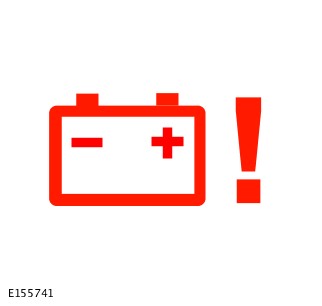
-
WARNING:
If either P0AA1-04 or P0AA4-04 diagnostic trouble codes (DTCs) are stored, the decommissioning procedure must not be carried out.
- Connect the Land Rover approved diagnostic equipment and carry out a diagnostic check on the high voltage system.
- If either P0AA1-04 or P0AA4-04 diagnostic trouble codes (DTCs) are stored, proceed to step 26
-
Raise and support the vehicleWARNING:
Make sure to support the vehicle with axle stands.
- Make sure that the transmission is in PARK with the engine and ignition switched off.
- Using the Land Rover approved diagnostic equipment locate the decommissioning procedure but do not start the process at this stage.
- Remove all smart keys least 5 metres away from the vehicle and lock in the designated key box.
-
Make sure that all external 12 volt sources are disconnected from the vehicle. For example; towbar sockets, 12 volt accessory sockets and charging points.WARNING:
All external 12 volt sources must be disconnected from the vehicle before proceeding.
-
Disconnect the primary battery ground cable.WARNING:
Make sure that the battery ground cable is placed securely away from the battery ground post.
Refer to:Specifications (414-00 Battery and Charging System - General Information, Specifications).
-
Disconnect the auxiliary battery ground cable.WARNING:
Make sure that the battery ground cable is placed securely away from the battery ground post.
Refer to:Specifications (414-00 Battery and Charging System - General Information, Specifications).
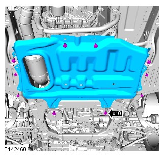
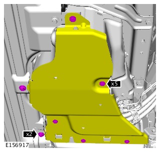
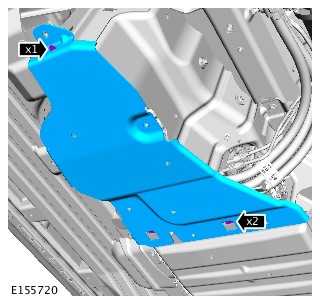
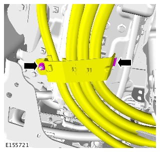
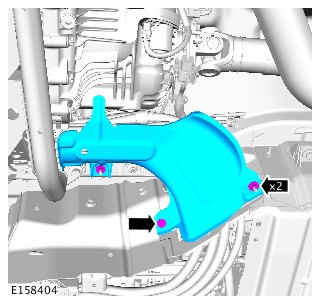
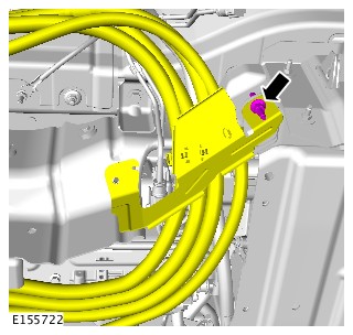
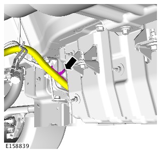
-
- Using the Land Rover approved diagnostic equipment start the decommissioning procedure and carry out the equipment safety test on the VM8105 special tool.
- Install the safety check connector to the female connector on the VM8105.
- Press the test button and wait for a test pass to be displayed on the screen.
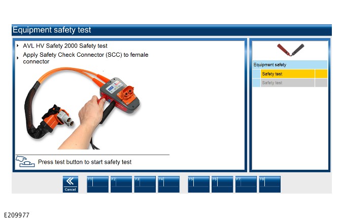
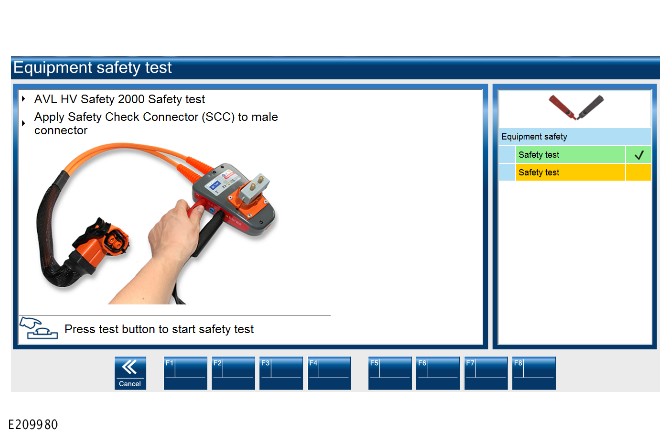
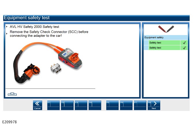
-
 WARNINGS:
-
Make sure that the recommended personal protection equipment is worn during this step. Failure to do so could result in serious injury.
-
The technician must wear Class 0 insulated rubber gloves and a safety visor during this step.
-
Do not carry out this step until the high voltage system has been allowed to completely discharge.
Release the HV connector locking lever and detach from the battery. -

-
Install the special tool blanking cap JLR-415-042 to the break-out box VM8105.Special Tool(s): JLR-415-042
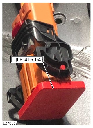
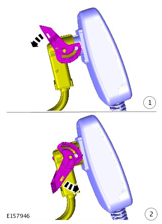
-
WARNINGS:
-
Make sure that the recommended personal protection equipment is worn during this step. Failure to do so could result in serious injury.
-
This step must be carried out in the exact sequence shown.
- Connect the special tool AVL 2000 voltage tester to the Land Rover approved diagnostic equipment.
- Connect the tester probes to the VM8105 on the vehicle as shown in the illustration.
- Resume the on screen instructions.
-
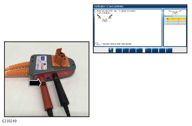
-
WARNINGS:
-
Make sure that the recommended personal protection equipment is worn during this step. Failure to do so could result in serious injury.
-
This step must be carried out in the exact sequence shown.
- Remove the black test probe (1) and connect to a suitable chassis earth.
- Resume the on screen instructions.
-
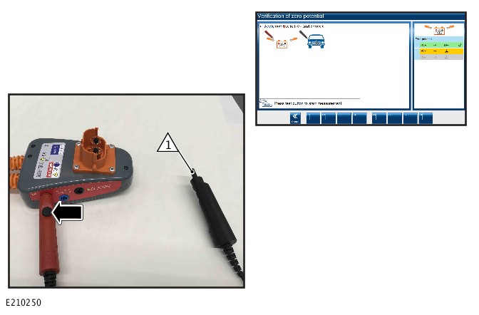
-
WARNINGS:
-
Make sure that the recommended personal protection equipment is worn during this step. Failure to do so could result in serious injury.
-
This step must be carried out in the exact sequence shown.
- Move the red test probe (1) and connect it to the negative input on the VM8105.
- Connect the black test probe (2) to a suitable chassis earth.
- Resume the on screen instructions.
-
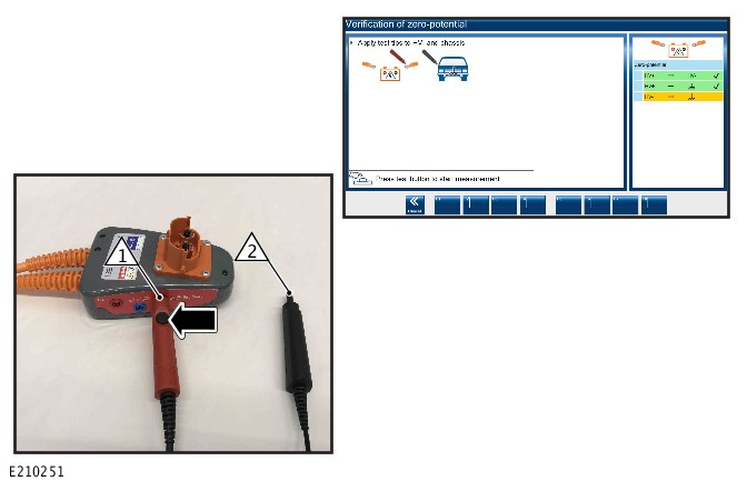
-
WARNINGS:
-
Make sure that the recommended personal protection equipment is worn during this step. Failure to do so could result in serious injury.
-
This step must be carried out in the exact sequence shown.
If the decommissioning procedure resulted in a pass, proceed to step 33. If the procedure did not result in a pass, proceed to the next step. -
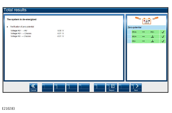
-
WARNINGS:
-
Make sure that the recommended personal protection equipment is worn during this step. Failure to do so could result in serious injury.
-
This step must be carried out in the exact sequence shown.
If the procedure resulted in a fail wait 5 minutes then repeat the decommissioning procedure from step 24. If the procedure results in another failure follow from steps 29-32 and quarantine the vehicle. -
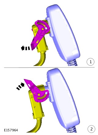
-
Remove the special tool blanking cap JLR-415-042 from the break-out box VM8105.Special Tool(s): JLR-415-042
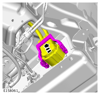
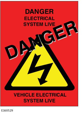
-
Disconnect the break-out boxVM8105 from the blanking plug.General Equipment: Hybrid Electric Vehicle (HEV) break-out box - VM8105General Equipment: Hybrid / Electric Vehicle Personal Protective Equipment (PPE)
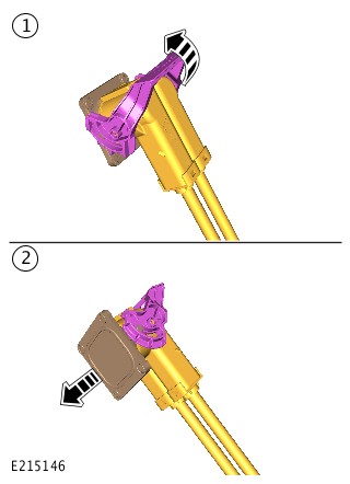
- The VM8105 must be retested before continuing, using the Land Rover approved diagnostic equipment repeat steps 18-20. If the re-test of VM8105 results in a pass continue to step 36. If the re-test resulted in a fail then another VM8105 must be acquired and the procedure started again from step 18.
-
WARNING:
Make sure that the special tool is located correctly.
Special Tool(s): JLR-415-009
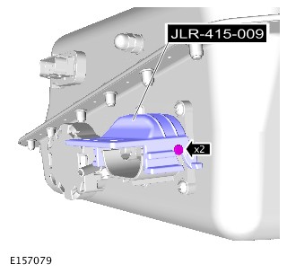
-
WARNING:
Make sure that the special tool is located correctly.
Special Tool(s): JLR-415-009
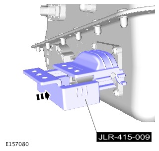
-
WARNING:
All padlock keys must be kept in the designated secured storage container away from the vehicle.
Using a suitable padlock, secure the special tool to the high voltage battery.Special Tool(s): JLR-415-009
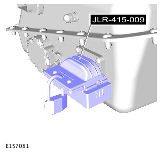

-
A Permit To Work (PTW) can now be issued by the EVAP using the instruction detailed in the EV safety rules.NOTE:
Only a EVAP trained technician can issue a PTW.
- Make sure the session file is saved on the approved Land Rover diagnostic tool.
- Carry out the system bonding test.
Refer to:Hybrid Electric Vehicle System Bonding Test (414-01 Battery, Mounting and Cables, General Procedures).
-
Remove the special tools.Special Tool(s): JLR-415-009
- Connect the auxiliary battery ground cable.
Refer to:Specifications (414-00 Battery and Charging System - General Information, Specifications).
- Connect the primary battery ground cable.
Refer to:Specifications (414-00 Battery and Charging System - General Information, Specifications).
- The EVAP must now sign the cancellation and power up sections of the PTW.
2017.0 RANGE ROVER SPORT (LW), 414-01
BATTERY, MOUNTING AND CABLES
HYBRID ELECTRIC VEHICLE POWER DOWN/UP (G1661160)
- 01.01.30
- HIGH VOLTAGE BATTERY - DISCONNECT
- 3000 CC, TDV6, DIESEL, HEV
- 0.60
- USED WITHINS
SPECIAL TOOL(S)
JLR-415-009
Hybrid Electric Vehicle (HEV) Battery Isolator
JLR-415-042
Blanking plug
GENERAL EQUIPMENT
| EQUIPMENT NAME |
|---|
| Hybrid / Electric Vehicle Personal Protective Equipment (PPE) |
| Hybrid Electric Vehicle (HEV) break-out box - VM8105 |
-
This procedure must be carried out in the exact sequence shown. Failure to do so could result in serious personal injury.
-
It is the responsibility of the EVAP/EVSAP to make sure they comply with any local legislation regarding working with High Voltages (HV) within this procedure.
-
This procedure requires the use Class 0 Personal Protective Equipment (PPE), all persons involved in this procedure must have read and understood the PPE requirements as detailed in section 414-01B Electric Vehicle Safety Rules.
-
The approved Personal Protective Equipment (PPE) must be worn where indicated by the orange PPE icons within this procedure, all persons involved in this procedure must have read and understood section 100-00 About This Manual before continuing.
-
All PPE equipment must be checked for wear or damage prior to use and replaced if damaged.
-
Approved personal protection equipment, to include; safety glasses or visor, black rubber gloves meeting the required standards and non-flammable, non-melting clothing, must be worn when instructed to do so.
-
All padlock keys must be kept in the designated secured storage container away from the vehicle.
Some components shown removed for clarity.
-
WARNING:
If either P0AA1-04 or P0AA4-04 diagnostic trouble codes (DTCs) are stored, the decommissioning procedure must not be carried out.
- Connect the Land Rover approved diagnostic equipment and carry out a diagnostic check on the high voltage system.
- If either P0AA1-04 or P0AA4-04 diagnostic trouble codes (DTCs) are stored, proceed to step 26
-
Raise and support the vehicleWARNING:
Make sure to support the vehicle with axle stands.
- Make sure that the transmission is in PARK with the engine and ignition switched off.
- Using the Land Rover approved diagnostic equipment locate the decommissioning procedure but do not start the process at this stage.
- Remove all smart keys least 5 metres away from the vehicle and lock in the designated key box.
-
Make sure that all external 12 volt sources are disconnected from the vehicle. For example; towbar sockets, 12 volt accessory sockets and charging points.WARNING:
All external 12 volt sources must be disconnected from the vehicle before proceeding.
-
Disconnect the primary battery ground cable.WARNING:
Make sure that the battery ground cable is placed securely away from the battery ground post.
Refer to:Specifications (414-00 Battery and Charging System - General Information, Specifications).
-
Disconnect the auxiliary battery ground cable.WARNING:
Make sure that the battery ground cable is placed securely away from the battery ground post.
Refer to:Specifications (414-00 Battery and Charging System - General Information, Specifications).
-
- Using the Land Rover approved diagnostic equipment start the decommissioning procedure and carry out the equipment safety test on the VM8105 special tool.
- Install the safety check connector to the female connector on the VM8105.
- Press the test button and wait for a test pass to be displayed on the screen.
-
WARNINGS:
-
Make sure that the recommended personal protection equipment is worn during this step. Failure to do so could result in serious injury.
-
The technician must wear Class 0 insulated rubber gloves and a safety visor during this step.
-
Do not carry out this step until the high voltage system has been allowed to completely discharge.
Release the HV connector locking lever and detach from the battery. -
-
Install the special tool blanking cap JLR-415-042 to the break-out box VM8105.Special Tool(s): JLR-415-042
-
WARNINGS:
-
Make sure that the recommended personal protection equipment is worn during this step. Failure to do so could result in serious injury.
-
This step must be carried out in the exact sequence shown.
- Connect the special tool AVL 2000 voltage tester to the Land Rover approved diagnostic equipment.
- Connect the tester probes to the VM8105 on the vehicle as shown in the illustration.
- Resume the on screen instructions.
-
-
WARNINGS:
-
Make sure that the recommended personal protection equipment is worn during this step. Failure to do so could result in serious injury.
-
This step must be carried out in the exact sequence shown.
- Remove the black test probe (1) and connect to a suitable chassis earth.
- Resume the on screen instructions.
-
-
WARNINGS:
-
Make sure that the recommended personal protection equipment is worn during this step. Failure to do so could result in serious injury.
-
This step must be carried out in the exact sequence shown.
- Move the red test probe (1) and connect it to the negative input on the VM8105.
- Connect the black test probe (2) to a suitable chassis earth.
- Resume the on screen instructions.
-
-
WARNINGS:
-
Make sure that the recommended personal protection equipment is worn during this step. Failure to do so could result in serious injury.
-
This step must be carried out in the exact sequence shown.
If the decommissioning procedure resulted in a pass, proceed to step 33. If the procedure did not result in a pass, proceed to the next step. -
-
WARNINGS:
-
Make sure that the recommended personal protection equipment is worn during this step. Failure to do so could result in serious injury.
-
This step must be carried out in the exact sequence shown.
If the procedure resulted in a fail wait 5 minutes then repeat the decommissioning procedure from step 24. If the procedure results in another failure follow from steps 29-32 and quarantine the vehicle. -
-
Remove the special tool blanking cap JLR-415-042 from the break-out box VM8105.Special Tool(s): JLR-415-042
-
Disconnect the break-out boxVM8105 from the blanking plug.General Equipment: Hybrid Electric Vehicle (HEV) break-out box - VM8105General Equipment: Hybrid / Electric Vehicle Personal Protective Equipment (PPE)
- The VM8105 must be retested before continuing, using the Land Rover approved diagnostic equipment repeat steps 18-20. If the re-test of VM8105 results in a pass continue to step 36. If the re-test resulted in a fail then another VM8105 must be acquired and the procedure started again from step 18.
-
WARNING:
Make sure that the special tool is located correctly.
Special Tool(s): JLR-415-009
-
WARNING:
Make sure that the special tool is located correctly.
Special Tool(s): JLR-415-009
-
WARNING:
All padlock keys must be kept in the designated secured storage container away from the vehicle.
Using a suitable padlock, secure the special tool to the high voltage battery.Special Tool(s): JLR-415-009
-
A Permit To Work (PTW) can now be issued by the EVAP using the instruction detailed in the EV safety rules.NOTE:
Only a EVAP trained technician can issue a PTW.
- Make sure the session file is saved on the approved Land Rover diagnostic tool.
- Carry out the system bonding test.
Refer to:Hybrid Electric Vehicle System Bonding Test (414-01 Battery, Mounting and Cables, General Procedures).
-
Remove the special tools.Special Tool(s): JLR-415-009
- Connect the auxiliary battery ground cable.
Refer to:Specifications (414-00 Battery and Charging System - General Information, Specifications).
- Connect the primary battery ground cable.
Refer to:Specifications (414-00 Battery and Charging System - General Information, Specifications).
- The EVAP must now sign the cancellation and power up sections of the PTW.
2017.0 RANGE ROVER SPORT (LW), 414-01
BATTERY, MOUNTING AND CABLES
HYBRID ELECTRIC VEHICLE SYSTEM BONDING TEST (G1671559)
- 01.01.31
- HEV SYSTEM ELECTRICAL BONDING TEST
- 3000 CC, TDV6, DIESEL, HEV
- 0.40
- USED WITHINS
-
If the vehicle has been decommissioned, do not re-commission the vehicle until all the bonding checks have been carried out and have passed (any concerns must be rectified).
-
If the vehicle is NOT decommissioned whilst carrying out this procedure, make sure that the hybrid electric vehicle (HEV) decommissioning procedure is followed before rectifying any concerns.
Make sure that the components are clean, dry and free from corrosion and foreign material.
-
CAUTION:
The probe at point 2 must be in direct contact with the casing, not the bonding strap or bonding strap fixing.
- Using Land Rover approved diagnostic equipment, carry out the HEV system bonding test application between the two points shown.
- Point 1: The HEV battery pack cradle bonding strap fixing.
- Point 2: The transfer case casing.
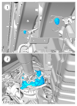
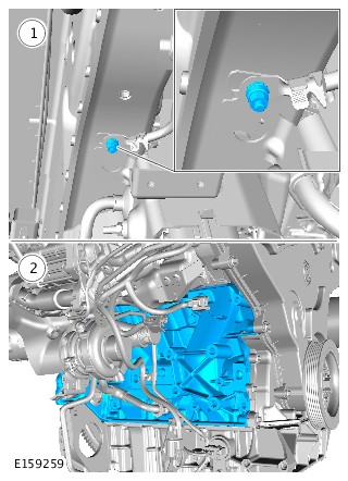
-
CAUTION:
The probe at point 2 must be in direct contact with the casing, not the bonding strap or bonding strap fixing.
- Using Land Rover approved diagnostic equipment, carry out the HEV system bonding test application between the two points shown.
- Point 1: The HEV battery pack cradle bonding strap fixing.
- Point 2: The electric power inverter converter (EPIC) casing.
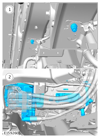
-
CAUTION:
The probe at point 2 must be in direct contact with the casing, not the bonding strap or bonding strap fixing.
- Using Land Rover approved diagnostic equipment, carry out the HEV system bonding test application between the two points shown.
- Point 1: The HEV battery pack cradle bonding strap fixing.
- Point 2: The HEV battery pack casing.
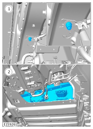
2017.0 RANGE ROVER SPORT (LW), 414-01
BATTERY, MOUNTING AND CABLES
HYBRID ELECTRIC VEHICLE BATTERY COOLING SYSTEM DRAINING, FILLING AND BLEEDING (G1707208)
- 15.10.38
- COOLANT - DRAINING, FILLING AND BLEEDING - HIGH VOLTAGE (HV) BATTERY PACK
- 3000 CC, TDV6, DIESEL, HEV
- 1.30
- USED WITHINS
SPECIAL TOOL(S)
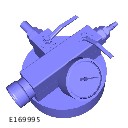
HU-919
Coolant System Vacuum Refill Kit
GENERAL EQUIPMENT
| EQUIPMENT NAME |
|---|
| Jaguar Land Rover approved diagnostic equipment |
Before disconnecting any components, make sure the area is clean and free from foreign material. When disconnected all openings must be sealed.
-
This procedure contains some variation in the illustrations depending on the vehicle specification, but the essential information is always correct.
-
This procedure contains illustrations showing certain components removed to provide extra clarity.
- Raise and support the vehicle on a suitable 2 post lift.
Refer to:Lifting (100-02 Jacking and Lifting, Description and Operation).
- Remove the rear right fender splash shield.
Refer to:Rear Fender Splash Shield (501-08 Exterior Trim and Ornamentation, Removal and Installation).
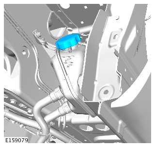
- Remove the right rear rocker panel moulding.
Refer to:Rear Rocker Panel Moulding (501-08 Exterior Trim and Ornamentation, Removal and Installation).
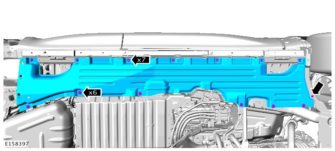

- Allow the coolant to drain into a suitable container.
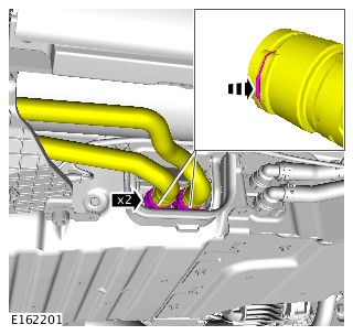
- Prepare a sufficient amount of coolant to the specified concentration.
Refer to:Specifications (303-03A Engine Cooling - TDV6 3.0L Diesel /TDV6 3.0L Diesel - Gen 1.5/TDV6 3.0L Diesel - Gen 2, Specifications).
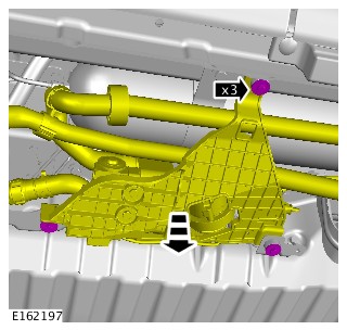
-
CAUTION:
Make sure the coolant supply valve is in the closed position on the special tool.
- Connect the hose from the vacuum refill adaptor into a container of clean coolant.
Special Tool(s): HU-919
- Connect a regulated compressed air supply to the venturi tube assembly.
- Install the cooling system vacuum refill adaptor to the expansion tank.
- Connect the hose from the vacuum refill adaptor into a container of clean coolant.
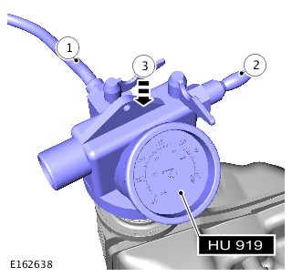
-
CAUTION:
Make sure the coolant supply valve is in the closed position on the vacuum filler gauge assembly.
Open the air supply valve until -0.8 Bar is shown on the gauge.Special Tool(s): HU-919
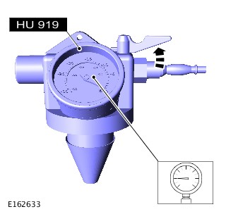
-
- Close the air supply valve.
Special Tool(s): HU-919
- Allow 1 minute to check the vacuum is held.
- Close the air supply valve.

-
Open the coolant supply valve and allow the coolant to be drawn into the system.Special Tool(s): HU-919
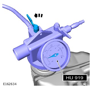
- Remove the special tool.
Special Tool(s): HU-919
-
Using the approved Jaguar Land Rover approved diagnostic equipment, run the battery coolant pump until the coolant level drops and coolant can be seen circulating around the system through the expansion tank.CAUTION:
If the coolant pump fails to run, the coolant pump has entered its run-dry mode. In this case the coolant pump assembly will require lowering further. This will make sure that the coolant pump is primed correctly and any air in the system is dispersed.
General Equipment: Jaguar Land Rover approved diagnostic equipment
- Check the coolant level in the HEV battery coolant expansion tank, top up as required.
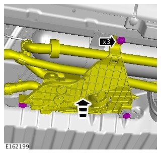
- Install the right rear rocker panel.
Refer to:Rear Rocker Panel Moulding (501-08 Exterior Trim and Ornamentation, Removal and Installation).
- Install the rear right fender splash shield.
Refer to:Rear Fender Splash Shield (501-08 Exterior Trim and Ornamentation, Removal and Installation).
2017.0 RANGE ROVER SPORT (LW), 414-01
BATTERY, MOUNTING AND CABLES
AUXILIARY BATTERY (G1551626)
- 86.15.09
- BATTERY - AUXILIARY - RENEW
- ALL DERIVATIVES
- 0.20
- USED WITHINS
- This procedure contains some variation in the illustrations depending on the vehicle specification, but the essential information is always correct.
- This procedure contains illustrations showing certain components removed to provide extra clarity.
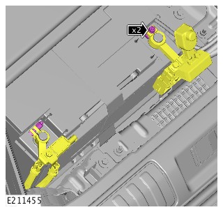
- Remove the right loadspace trim panel.
Refer to:Right Loadspace Trim Panel (501-05 Interior Trim and Ornamentation, Removal and Installation).
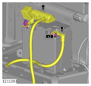
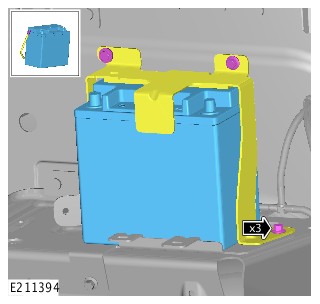
-
- Install the auxiliary battery.
- Connect the vent hose.
- Install the battery clamp.
Torque: 9Nm
-
- Connect the auxiliary battery positive cable.
Torque: 6Nm
- Connect the auxiliary battery ground cable.
Torque: 6Nm
- Connect the auxiliary battery positive cable.
- Install the right loadspace side trim panel.
Refer to:Right Loadspace Trim Panel (501-05 Interior Trim and Ornamentation, Removal and Installation).
-
- Connect the startup battery positive cable.
Torque: 6Nm
- Connect the startup battery ground cable.
Torque: 6Nm
- Connect the startup battery positive cable.
- Install the tool kit tray.
-
Install the loadspace floor trim panelNOTE:
Do not carry out the battery reset procedure on the Jaguar Land Rover approved diagnostic as there is no Battery Monitoring System (BMS) on the auxiliary battery.
2017.0 RANGE ROVER SPORT (LW), 414-01
BATTERY, MOUNTING AND CABLES
BATTERY - VEHICLES WITHOUT: 7 SEATS (G1558977)
- 86.15.01
- STARTUP BATTERY - RENEW
- 2000 CC, INGENIUM DIESEL
- 0.40
- USED WITHINS
- 86.15.01
- STARTUP BATTERY - RENEW
- 2000 CC, SI4
- 0.40
- USED WITHINS
- 86.15.01
- STARTUP BATTERY - RENEW
- 3000 CC, AJ V6 (AJ126)
- 0.40
- USED WITHINS
- 86.15.01
- STARTUP BATTERY - RENEW
- 3000 CC, TDV6
- 0.40
- USED WITHINS
- 86.15.01
- STARTUP BATTERY - RENEW
- 4400 CC, TDV8
- 0.40
- USED WITHINS
- 86.15.01
- STARTUP BATTERY - RENEW
- 5000 CC, AJ V8
- 0.40
- USED WITHINS
GENERAL EQUIPMENT
| EQUIPMENT NAME |
|---|
| Jaguar Land Rover approved diagnostic equipment |
- This procedure contains some variation in the illustrations depending on the vehicle specification, but the essential information is always correct.
- This procedure contains illustrations showing certain components removed to provide extra clarity.
-
- Install the battery.
- Secure the battery with the fabric strap.
Torque: 9Nm
- Install the vent hose.
-
CAUTIONS:
-
Make sure the battery monitoring system (BMS) electrical connector is connected to the module, before installing the BMS on to the battery terminal.
-
Make sure the clamping lug on the BMS is below the top of the negative terminal post as shown.
Connect the startup battery positive cable.Torque: 6Nm -
- Install the positive terminal cover.
- Connect the startup battery ground cable.
Torque: 6Nm
- Install the tool kit tray.
- Install the loadspace floor panel.
- Install the right loadspace trim panel.
- Complete the battery rest procedure using the approved Jaguar Land Rover diagnostic equipment.
2017.0 RANGE ROVER SPORT (LW), 414-01
BATTERY, MOUNTING AND CABLES
BATTERY - VEHICLES WITH: 7 SEATS (G1716321)
- 86.15.01
- STARTUP BATTERY - RENEW
- 2000 CC, INGENIUM DIESEL
- 0.40
- USED WITHINS
- 86.15.01
- STARTUP BATTERY - RENEW
- 2000 CC, SI4
- 0.40
- USED WITHINS
- 86.15.01
- STARTUP BATTERY - RENEW
- 3000 CC, AJ V6 (AJ126)
- 0.40
- USED WITHINS
- 86.15.01
- STARTUP BATTERY - RENEW
- 3000 CC, TDV6
- 0.40
- USED WITHINS
- 86.15.01
- STARTUP BATTERY - RENEW
- 4400 CC, TDV8
- 0.40
- USED WITHINS
- 86.15.01
- STARTUP BATTERY - RENEW
- 5000 CC, AJ V8
- 0.40
- USED WITHINS
-
Some variation in the illustrations may occur, but the essential information is always correct.
-
Removal steps in this procedure may contain installation details.
-
If a new battery is installed, the battery monitoring system (BMS) must be reset using Land Rover approved diagnostic equipment.
-
CAUTIONS:
-
Make sure that the air suspension compressor is located correctly in its mounting bracket.
-
Make sure that the battery monitoring system (BMS) module wiring harness does not get caught beneath the battery securing clamp.
-
Make sure that the battery is positioned fully outboard on the battery tray and that no harnesses or hoses are trapped.
-
Make sure that the component is correctly located on its mounting bracket. Lift the component by 10mm before lowering into position.
-
Make sure the battery monitoring system (BMS) electrical connector is connected to the module, before installing the BMS on to the battery terminal.
To install, reverse the removal procedure. -
-
Using Land Rover approved diagnostic equipment, reset the battery monitoring system (BMS).NOTE:
This step is only necessary when installing a new battery.
2017.0 RANGE ROVER SPORT (LW), 414-01
BATTERY, MOUNTING AND CABLES
BATTERY TRAY (G1716335)
- 86.15.11
- BATTERY CARRIER - RENEW
- 2000 CC, INGENIUM DIESEL
- 0.40
- USED WITHINS
- 86.15.11
- BATTERY CARRIER - RENEW
- 2000 CC, SI4
- 0.40
- USED WITHINS
- 86.15.11
- BATTERY CARRIER - RENEW
- 3000 CC, AJ V6 (AJ126)
- 0.40
- USED WITHINS
- 86.15.11
- BATTERY CARRIER - RENEW
- 3000 CC, TDV6
- 0.40
- USED WITHINS
- 86.15.11
- BATTERY CARRIER - RENEW
- 4400 CC, TDV8
- 0.40
- USED WITHINS
- 86.15.11
- BATTERY CARRIER - RENEW
- 5000 CC, AJ V8
- 0.40
- USED WITHINS
Removal steps in this procedure may contain installation details.
- Remove the battery.
Refer to:Battery - Vehicles Without: 7 Seats (414-01 Battery, Mounting and Cables, Removal and Installation).
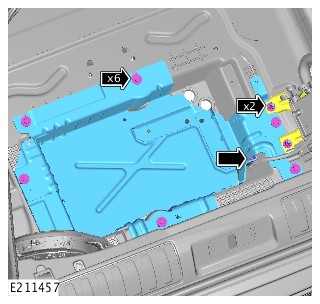
- Install the startup battery tray.
TorqueBattery tray to body bolts: 5NmTraction battery heater bracket nuts: 10Nm
- Install the startup battery.
Refer to:Battery - Vehicles Without: 7 Seats (414-01 Battery, Mounting and Cables, Removal and Installation).
2017.0 RANGE ROVER SPORT (LW), 414-01
BATTERY, MOUNTING AND CABLES
HYBRID ELECTRIC VEHICLE BATTERY - VEHICLES WITH: 8HP70H 8-SPEED AUTOMATIC TRANSMISSION, VEHICLES WITH: SDV6 3.0L DIESEL - HYBRID ELECTRIC VEHICLE (G1661161)
- 15.10.13
- HIGH VOLTAGE BATTERY PACK - RENEW
- 3000 CC, TDV6, DIESEL, HEV
- 4.10
- USED WITHINS
This procedure can only be carried out after the vehicle has been decommissioned, by an approved person.
Some variation in the illustrations may occur, but the essential information is always correct.
-
Refer to:Hybrid Electric Vehicle Battery Pack Cradle - Vehicles With: 8HP70H 8-Speed Automatic Transmission, Vehicles With: SDV6 3.0L Diesel - Hybrid Electric Vehicle (414-01 Battery, Mounting and Cables, Removal and Installation).
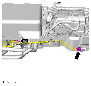

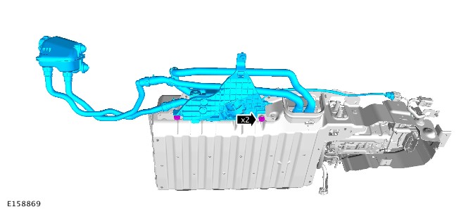
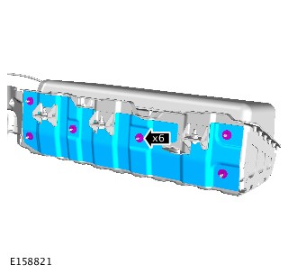
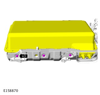
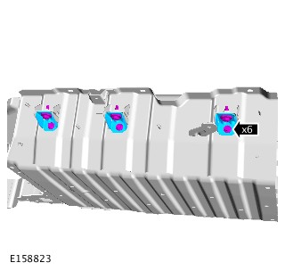
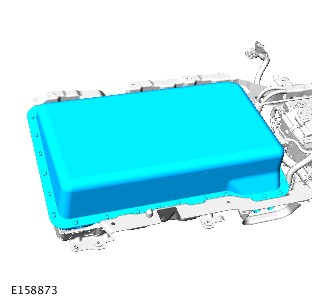
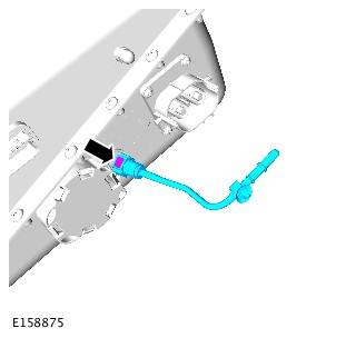
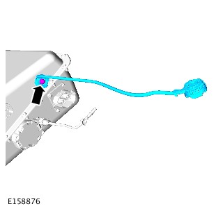
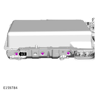
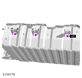
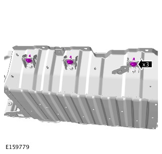
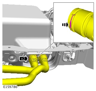
-
Refer to:Hybrid Electric Vehicle Battery Pack Cradle - Vehicles With: 8HP70H 8-Speed Automatic Transmission, Vehicles With: SDV6 3.0L Diesel - Hybrid Electric Vehicle (414-01 Battery, Mounting and Cables, Removal and Installation).
2017.0 RANGE ROVER SPORT (LW), 414-01
BATTERY, MOUNTING AND CABLES
HYBRID ELECTRIC VEHICLE BATTERY PACK CRADLE - VEHICLES WITH: 8HP70H 8-SPEED AUTOMATIC TRANSMISSION, VEHICLES WITH: SDV6 3.0L DIESEL - HYBRID ELECTRIC VEHICLE (G1701399)
- 15.10.05.99
- CARRIER - BATTERY PACK - REMOVE FOR ACCESS AND REFIT
- 3000 CC, TDV6, DIESEL, HEV
- 4.40
- USED WITHINS
GENERAL EQUIPMENT
| EQUIPMENT NAME |
|---|
| Transmission jack |
This procedure can only be carried out after the vehicle has been decommissioned, by an approved person.
Some variation in the illustrations may occur, but the essential information is always correct.
- Decommission the vehicle.
Refer to:Hybrid Electric Vehicle Power Down/Up (414-01 Battery, Mounting and Cables, General Procedures).
-
Refer to:Cooling System Draining and Vacuum Filling (303-03A Engine Cooling - TDV6 3.0L Diesel /TDV6 3.0L Diesel - Gen 1.5/TDV6 3.0L Diesel - Gen 2, General Procedures).
-
Refer to:Air Conditioning System Recovery, Evacuation and Charging (412-00 Climate Control System - General Information, General Procedures).
-
NOTE:
RH side only.
Refer to:Rear Rocker Panel Moulding (501-08 Exterior Trim and Ornamentation, Removal and Installation).
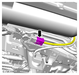
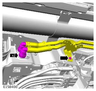
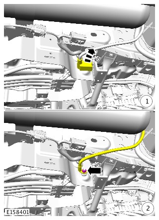
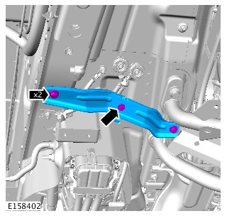
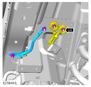
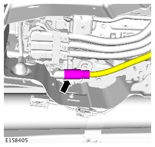
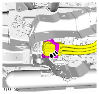
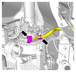
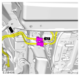
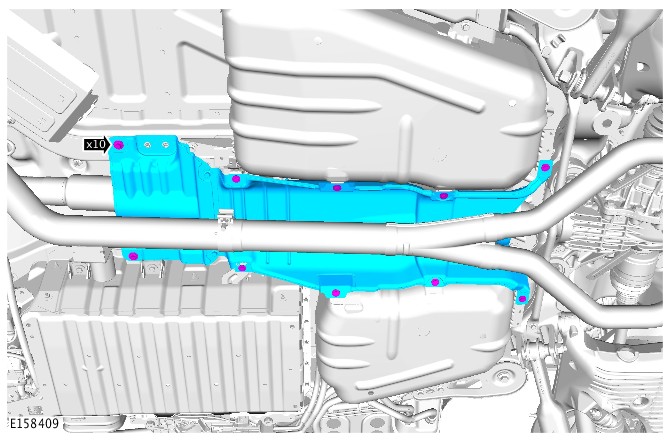
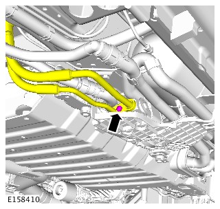
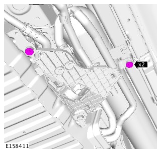
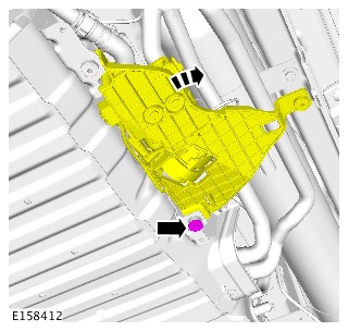
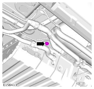
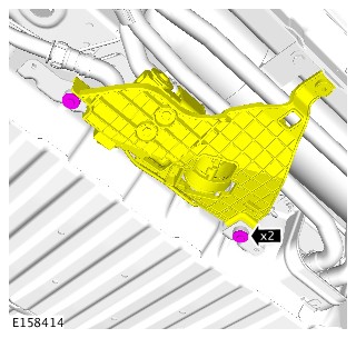
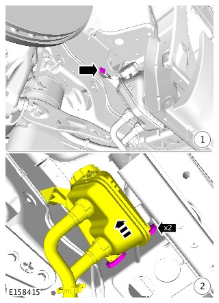
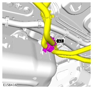
-
WARNING:
Secure the battery cradle to the transmission jack.
General Equipment: Transmission jack
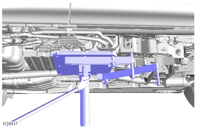
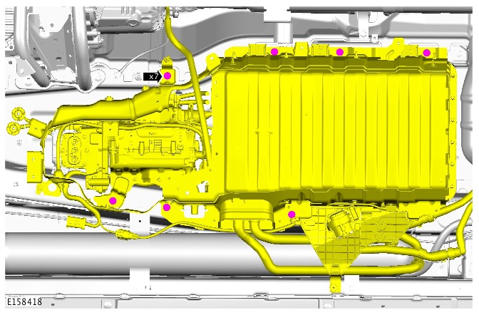
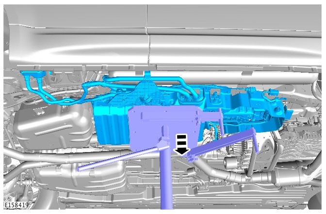
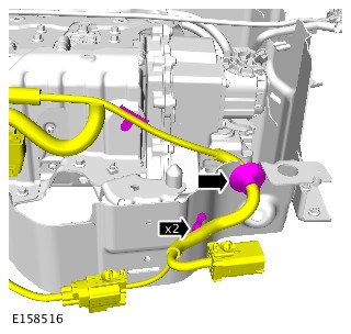

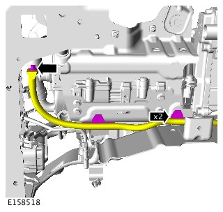
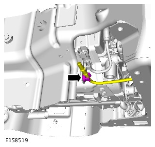
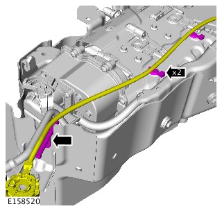
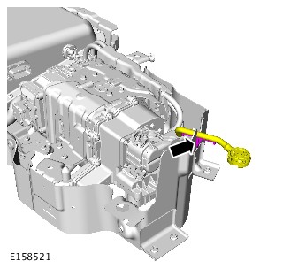
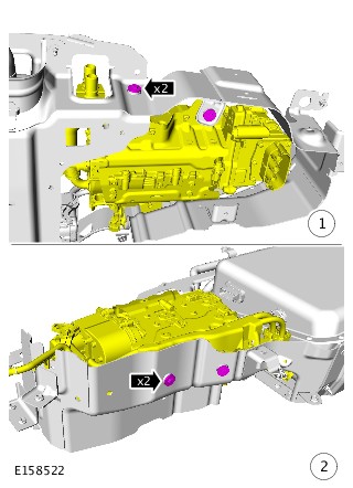
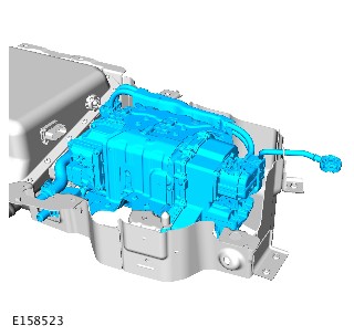
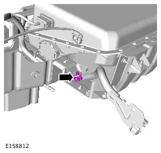
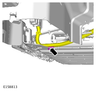
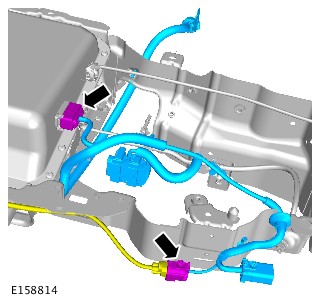
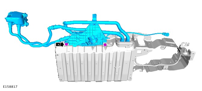
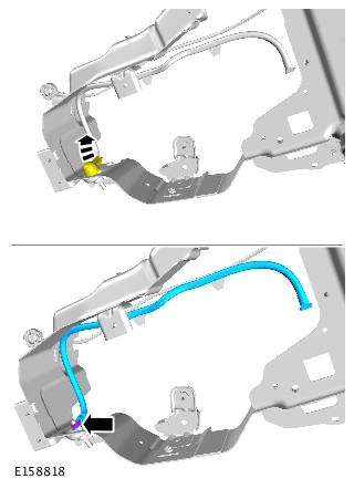
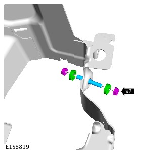
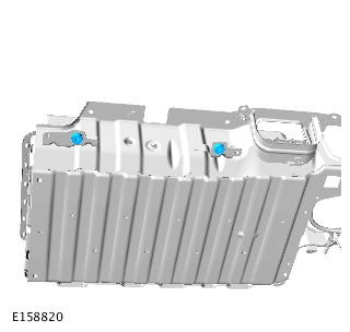
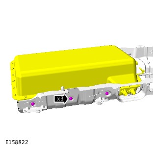
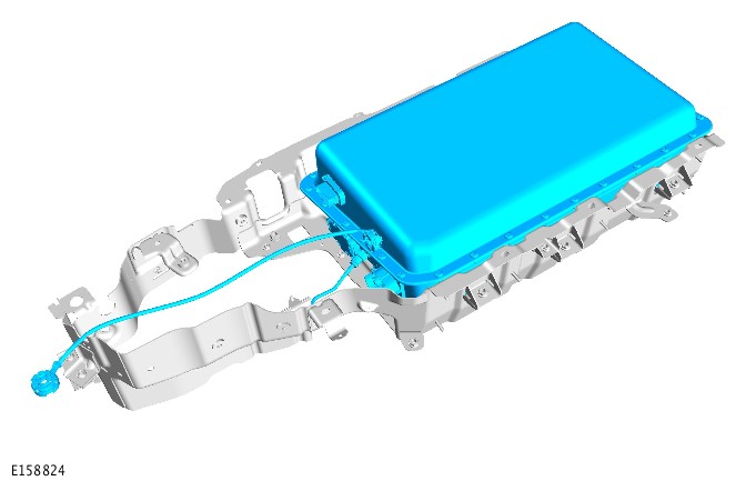
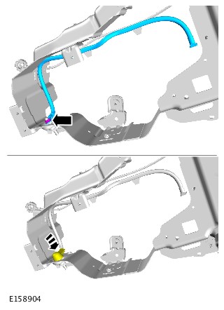
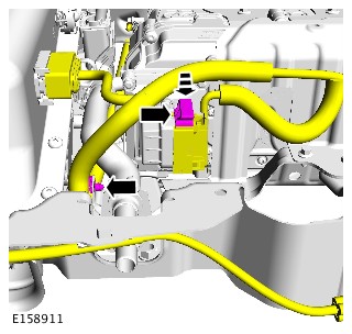

-
Remove the equipment illustrated.General Equipment: Transmission jack
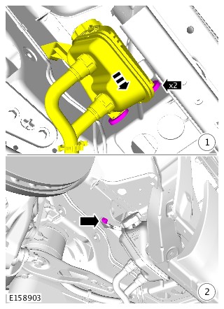
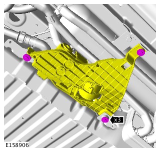
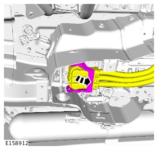
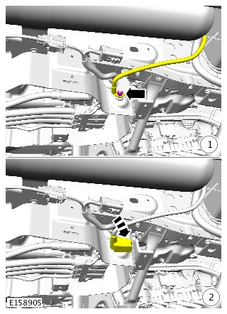
-
Refer to:Hybrid Electric Vehicle System Bonding Test (414-01 Battery, Mounting and Cables, General Procedures).
-
Refer to:Hybrid Electric Vehicle Power Down/Up (414-01 Battery, Mounting and Cables, General Procedures).
-
Add coolant to the battery coolant expansion tank as required, until the upper level mark is achieved.CAUTION:
The coolant pump assembly requires lowering and supported by the coolant hoses during this procedure.
-
Using Land Rover approved diagnostic equipment, run the battery coolant pump until the coolant level drops and coolant can be seen circulating around the system through the expansion tank.CAUTIONS:
-
The coolant pump assembly requires lowering and supported by the coolant hoses during this procedure.
-
If the coolant pump fails to run, the coolant pump has entered its run-dry mode. In this case the coolant pump assembly will require lowering further. This will make sure that the coolant pump is primed correctly and any air in the system is dispersed.
-
- Fill the coolant level in the battery coolant expansion tank, to the maximum cold fill line.
-
NOTE:
RH side only.
Refer to:Rear Rocker Panel Moulding (501-08 Exterior Trim and Ornamentation, Removal and Installation).
-
Refer to:Air Conditioning System Recovery, Evacuation and Charging (412-00 Climate Control System - General Information, General Procedures).
-
Refer to:Cooling System Draining and Vacuum Filling (303-03A Engine Cooling - TDV6 3.0L Diesel /TDV6 3.0L Diesel - Gen 1.5/TDV6 3.0L Diesel - Gen 2, General Procedures).
2017.0 RANGE ROVER SPORT (LW), 414-01
BATTERY, MOUNTING AND CABLES
ELECTRIC POWER INVERTER CONVERTER - VEHICLES WITH: 8HP70 8-SPEED - HYBRID ELECTRIC VEHICLE - AUTOMATIC TRANSMISSION – AWD (G1661164)
- 15.10.04
- POWER INVERTER - RENEW
- 3000 CC, TDV6, DIESEL, HEV
- 4.20
- USED WITHINS
This procedure can only be carried out after the vehicle has been decommissioned, by an approved person.
-
Removal steps in this procedure may contain installation details.
-
Some variation in the illustrations may occur, but the essential information is always correct.
-
Refer to:Hybrid Electric Vehicle Battery Pack Cradle - Vehicles With: 8HP70H 8-Speed Automatic Transmission, Vehicles With: SDV6 3.0L Diesel - Hybrid Electric Vehicle (414-01 Battery, Mounting and Cables, Removal and Installation).
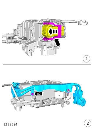
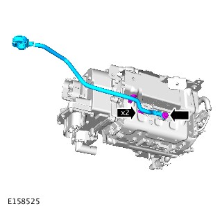
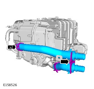
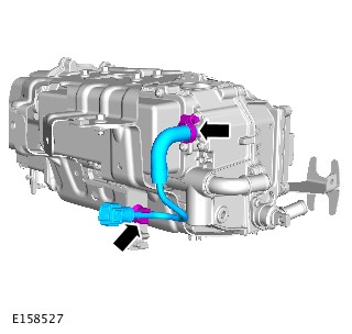
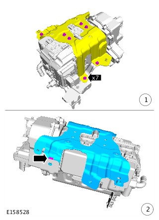
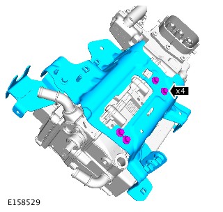
- To install, reverse the removal procedure.
2017.0 RANGE ROVER SPORT (LW), 414-01
BATTERY, MOUNTING AND CABLES
HYBRID ELECTRIC VEHICLE BATTERY EXPANSION TANK - VEHICLES WITH: 8HP70H 8-SPEED AUTOMATIC TRANSMISSION, VEHICLES WITH: SDV6 3.0L DIESEL - HYBRID ELECTRIC VEHICLE (G1661165)
- 15.10.10
- EXPANSION TANK - BATTERY PACK COOLER - RENEW
- 3000 CC, TDV6, DIESEL, HEV
- 0.60
- USED WITHINS
-
Raise and support the vehicle.WARNING:
Make sure to support the vehicle with axle stands.
- Remove the rear right fender splash shield.
Refer to:Rear Fender Splash Shield (501-08 Exterior Trim and Ornamentation, Removal and Installation).
- Using a suitable syringe, remove the coolant from the expansion tank.
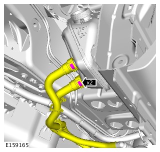
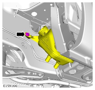
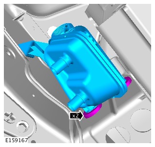
- Fill the coolant level in the battery coolant expansion tank, to the maximum cold fill line.
- Install the rear right fender splash shield.
Refer to:Rear Fender Splash Shield (501-08 Exterior Trim and Ornamentation, Removal and Installation).
2017.0 RANGE ROVER SPORT (LW), 414-01
BATTERY, MOUNTING AND CABLES
HYBRID ELECTRIC VEHICLE BATTERY COOLANT PUMP - VEHICLES WITH: 8HP70H 8-SPEED AUTOMATIC TRANSMISSION, VEHICLES WITH: SDV6 3.0L DIESEL - HYBRID ELECTRIC VEHICLE (G1701400)
- 15.10.15
- COOLANT PUMP - HIGH VOLTAGE BATTERY PACK - RENEW
- 3000 CC, TDV6, DIESEL, HEV
- 1.50
- USED WITHINS
Some variation in the illustrations may occur, but the essential information is always correct.
-
Raise and support the vehicle.WARNING:
Make sure to support the vehicle with axle stands.
- Remove the rear right fender splash shield.
Refer to:Rear Fender Splash Shield (501-08 Exterior Trim and Ornamentation, Removal and Installation).
-
NOTE:
RH side only.
Refer to:Rear Rocker Panel Moulding (501-08 Exterior Trim and Ornamentation, Removal and Installation).
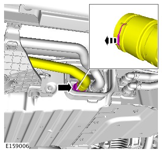
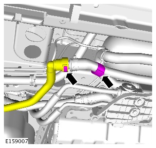
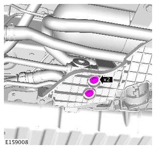
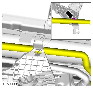
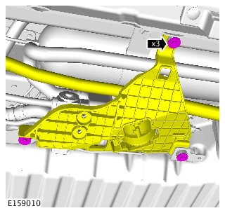
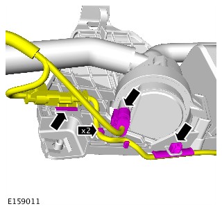
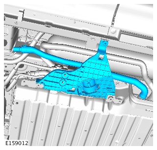
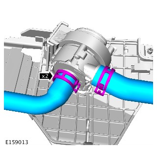
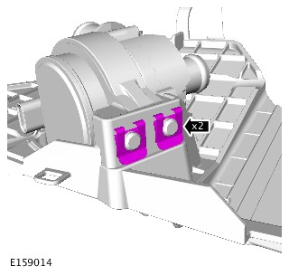
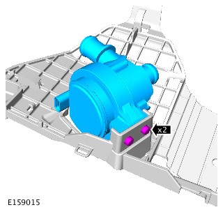
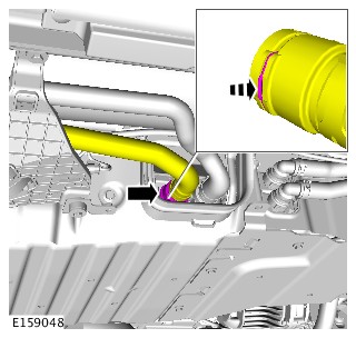
-
Add coolant to the battery coolant expansion tank as required, until the upper level mark is achieved.CAUTION:
The coolant pump assembly needs to be lowered and suspended by the coolant hoses during this procedure.
-
Using Land Rover approved diagnostic equipment, run the battery coolant pump until the coolant level drops and coolant can be seen circulating around the system through the expansion tank.CAUTIONS:
-
The coolant pump assembly needs to be lowered and suspended by the coolant hoses during this procedure.
-
If the coolant pump fails to run, the coolant pump has entered its run-dry mode. In this case the coolant pump assembly will require lowering further. This will make sure that the coolant pump is primed correctly and any air in the system is dispersed.
-
- Fill the coolant level in the battery coolant expansion tank, to the maximum cold fill line.
-
Refer to:Rear Rocker Panel Moulding (501-08 Exterior Trim and Ornamentation, Removal and Installation).
- Install the rear right fender splash shield.
Refer to:Rear Fender Splash Shield (501-08 Exterior Trim and Ornamentation, Removal and Installation).
2017.0 RANGE ROVER SPORT (LW), 414-01
BATTERY, MOUNTING AND CABLES
3-PHASE HIGH VOLTAGE CABLE - VEHICLES WITH: 8HP70H 8-SPEED AUTOMATIC TRANSMISSION, VEHICLES WITH: SDV6 3.0L DIESEL - HYBRID ELECTRIC VEHICLE (G1661167)
- 15.10.06
- CABLING - 3 PHASE HIGH VOLTAGE - RENEW
- 3000 CC, TDV6, DIESEL, HEV
- 1.50
- USED WITHINS
This procedure can only be carried out after the vehicle has been decommissioned, by an approved person.
Removal steps in this procedure may contain installation details.
- Decommission the vehicle.
Refer to:Hybrid Electric Vehicle Power Down/Up (414-01 Battery, Mounting and Cables, General Procedures).
-
WARNING:
Make sure to support the vehicle with axle stands.
- Raise and support the vehicle.
-
Refer to:Transmission Support Crossmember - TDV6 3.0L Diesel /TDV6 3.0L Diesel - Gen 1.5/TDV6 3.0L Diesel - Gen 2 (502-02 Full Frame and Body Mounting, Removal and Installation).
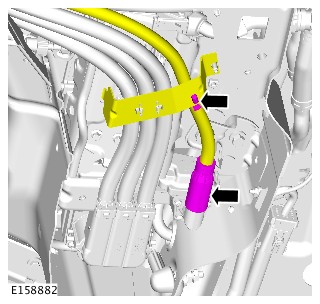
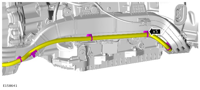
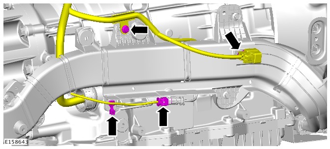
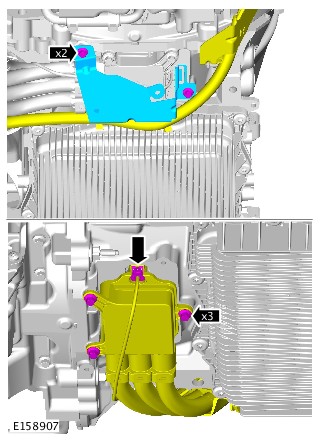
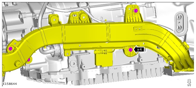
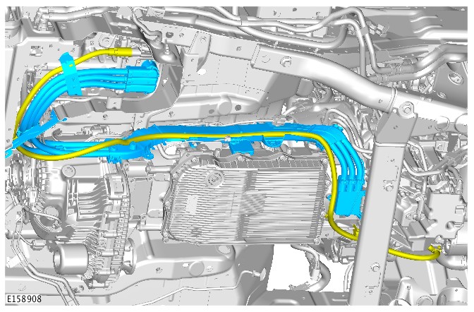
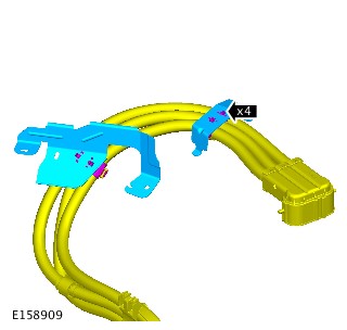
- To install, reverse the removal procedure.
2017.0 RANGE ROVER SPORT (LW), 414-01
BATTERY, MOUNTING AND CABLES
HIGH VOLTAGE CABLES - VEHICLES WITH: 8HP70H 8-SPEED AUTOMATIC TRANSMISSION, VEHICLES WITH: SDV6 3.0L DIESEL - HYBRID ELECTRIC VEHICLE (G1661168)
- 15.10.14
- CABLE - HIGH VOLTAGE BATTERY PACK TO POWER INVERTER - RENEW
- 3000 CC, TDV6, DIESEL, HEV
- 4.00
- USED WITHINS
- 12.53.13
- DRIVE PLATE - AUTOMATIC - RENEW
- 2000 CC, INGENIUM DIESEL, WITH PARTICULATE FILTER, WITH DIESEL EXHAUST FLUID
- 5.70
- USED WITHINS
- 12.53.13
- DRIVE PLATE - AUTOMATIC - RENEW
- 2000 CC, INGENIUM DIESEL, WITH PARTICULATE FILTER, WITHOUT DIESEL EXHAUST FLUID
- 5.60
- USED WITHINS
- 12.53.13
- DRIVE PLATE - AUTOMATIC - RENEW
- 3000 CC, AJ V6 (AJ126)
- 5.30
- USED WITHINS
- 12.53.13
- DRIVE PLATE - AUTOMATIC - RENEW
- 3000 CC, TDV6, DIESEL, WITH PARTICULATE FILTER, WITH DIESEL EXHAUST FLUID, HEV
- 7.30
- USED WITHINS
- 12.53.13
- DRIVE PLATE - AUTOMATIC - RENEW
- 3000 CC, TDV6, DIESEL, WITH PARTICULATE FILTER, WITH DIESEL EXHAUST FLUID, IC
- 6.10
- USED WITHINS
- 12.53.13
- DRIVE PLATE - AUTOMATIC - RENEW
- 3000 CC, TDV6, DIESEL, WITH PARTICULATE FILTER, WITHOUT DIESEL EXHAUST FLUID, HEV
- 6.90
- USED WITHINS
- 12.53.13
- DRIVE PLATE - AUTOMATIC - RENEW
- 3000 CC, TDV6, DIESEL, WITH PARTICULATE FILTER, WITHOUT DIESEL EXHAUST FLUID, IC
- 6.10
- USED WITHINS
- 12.53.13
- DRIVE PLATE - AUTOMATIC - RENEW
- 4400 CC, TDV8, WITH PARTICULATE FILTER, WITH DIESEL EXHAUST FLUID
- 6.70
- USED WITHINS
- 12.53.13
- DRIVE PLATE - AUTOMATIC - RENEW
- 4400 CC, TDV8, WITH PARTICULATE FILTER, WITHOUT DIESEL EXHAUST FLUID
- 6.60
- USED WITHINS
- 12.53.13
- DRIVE PLATE - AUTOMATIC - RENEW
- 4400 CC, TDV8, WITHOUT PARTICULATE FILTER
- 6.50
- USED WITHINS
- 12.53.13
- DRIVE PLATE - AUTOMATIC - RENEW
- 5000 CC, AJ V8
- 5.70
- USED WITHINS
This procedure can only be carried out after the vehicle has been decommissioned, by an approved person.
Removal steps in this procedure may contain installation details.
- Decommission the vehicle.
Refer to:Hybrid Electric Vehicle Power Down/Up (414-01 Battery, Mounting and Cables, General Procedures).
-
WARNING:
Make sure to support the vehicle with axle stands.
- Raise and support the vehicle.
-
Refer to:Electric Power Inverter Converter - Vehicles With: 8HP70 8-Speed - Hybrid Electric Vehicle - Automatic Transmission – AWD (414-01 Battery, Mounting and Cables, Removal and Installation).
- To install, reverse the removal procedure.
2017.0 RANGE ROVER SPORT (LW), 414-01
BATTERY, MOUNTING AND CABLES
HIGH VOLTAGE CABLE - VEHICLES WITH: 8HP70H 8-SPEED AUTOMATIC TRANSMISSION, VEHICLES WITH: SDV6 3.0L DIESEL - HYBRID ELECTRIC VEHICLE (G1661169)
- 15.10.07
- CABLE - ELECTRIC AIR COMPRESSOR (EAC) - RENEW
- 3000 CC, TDV6, DIESEL, HEV
- 1.60
- USED WITHINS
This procedure can only be carried out after the vehicle has been decommissioned, by an approved person.
Removal steps in this procedure may contain installation details.
- Decommission the vehicle.
Refer to:Hybrid Electric Vehicle Power Down/Up (414-01 Battery, Mounting and Cables, General Procedures).
-
WARNING:
Make sure to support the vehicle with axle stands.
- Raise and support the vehicle.
-
Refer to:Transmission Support Crossmember - TDV6 3.0L Diesel /TDV6 3.0L Diesel - Gen 1.5/TDV6 3.0L Diesel - Gen 2 (502-02 Full Frame and Body Mounting, Removal and Installation).
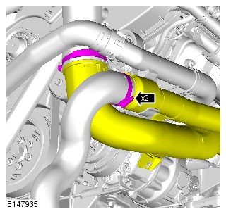
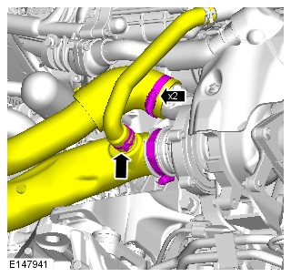
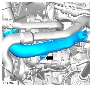
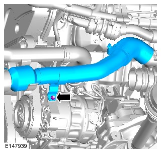
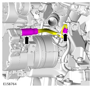
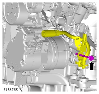
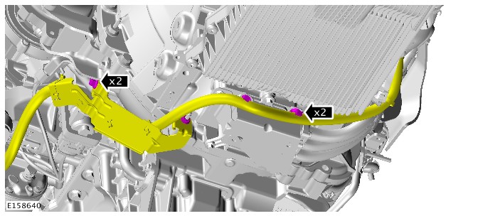
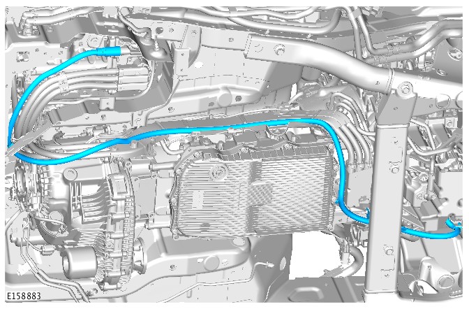
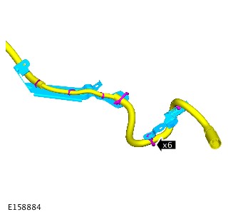
- To install, reverse the removal procedure.
2017.0 RANGE ROVER SPORT (LW), 414-01
BATTERY, MOUNTING AND CABLES
HYBRID ELECTRIC VEHICLE BATTERY COOLER AND ISOLATION VALVE - VEHICLES WITH: 8HP70H 8-SPEED AUTOMATIC TRANSMISSION, VEHICLES WITH: SDV6 3.0L DIESEL - HYBRID ELECTRIC VEHICLE (G1701401)
- 15.10.08
- COOLER - BATTERY PACK AND THERMOSTATIC EXPANSION VALVE - RENEW
- 3000 CC, TDV6, DIESEL, HEV
- 1.80
- USED WITHINS
PART(S)
| STEP | PART NAME | QUANTITY |
|---|---|---|
| Installation Step 9 | Air conditioning pipe O-ring seal(s) | 1 |
Some variation in the illustrations may occur, but the essential information is always correct.
-
Raise and support the vehicle.WARNING:
Make sure to support the vehicle with axle stands.
-
Refer to:Air Conditioning System Recovery, Evacuation and Charging (412-00 Climate Control System - General Information, General Procedures).
- Remove the rear right fender splash shield.
Refer to:Rear Fender Splash Shield (501-08 Exterior Trim and Ornamentation, Removal and Installation).
-
NOTE:
RH side only.
Refer to:Rear Rocker Panel Moulding (501-08 Exterior Trim and Ornamentation, Removal and Installation).
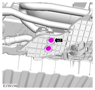
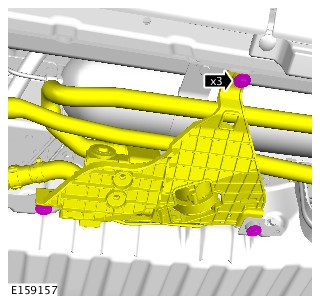
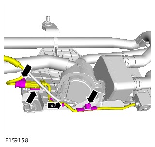
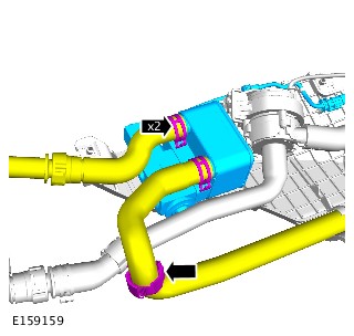
-
Add coolant to the battery coolant expansion tank as required, until the upper level mark is achieved.CAUTION:
The coolant pump assembly requires lowering and supported by the coolant hoses during this procedure.
-
Using Land Rover approved diagnostic equipment, run the battery coolant pump until the coolant level drops and coolant can be seen circulating around the system through the expansion tank.CAUTIONS:
-
The coolant pump assembly requires lowering and supported by the coolant hoses during this procedure.
-
If the coolant pump fails to run, the coolant pump has entered its run-dry mode. In this case the coolant pump assembly will require lowering further. This will make sure that the coolant pump is primed correctly and any air in the system is dispersed.
-
- Fill the coolant level in the battery coolant expansion tank, to the maximum cold fill line.
-
Refer to:Rear Rocker Panel Moulding (501-08 Exterior Trim and Ornamentation, Removal and Installation).
- Install the rear right fender splash shield.
Refer to:Rear Fender Splash Shield (501-08 Exterior Trim and Ornamentation, Removal and Installation).
-
Refer to:Air Conditioning System Recovery, Evacuation and Charging (412-00 Climate Control System - General Information, General Procedures).