Range Rover Sport / L494 2017 ELECTRICAL CLIMATE CONTROL USER MANUAL
412: Climate Control System
412-00: Climate Control System - General Information
CLIMATE CONTROL (G1618351)
Torque Specifications
| DESCRIPTION | NM | LB-FT | LB-IN |
|---|---|---|---|
| Air conditioning (A/C) compressor refrigerant line clamp to radiator bolt | 7 | - | 62 |
| A/C compressor refrigerant line clamp to engine nut - vehicles with 3.0L diesel | 6 | - | 53 |
| A/C compressor refrigerant lines retaining nuts - vehicles with 3.0L diesel | 18 | 14 | - |
| A/C compressor refrigerant line clamp to engine nuts - vehicles with 4.4L diesel | 9 | 80 | |
| A/C compressor refrigerant lines retaining nuts- vehicles with 4.4L diesel | 9 | 80 | |
| A/C refrigerant lines clamp to evaporator connector block bolt | 10 | 7 | - |
| A/C compressor refrigerant line retaining nuts - vehicles with 3.0L and 5.0L petrol | 18 | 14 | - |
| A/C compressor retaining bolts | 25 | 18 | - |
| A/C condenser core refrigerant line nuts | 8 | - | 71 |
| A/C condenser fan cowl bolts - vehicles with 3.0L and 5.0L petrol | 7 | - | 62 |
| A/C condenser core to radiator bolts | 4.5 | - | 40 |
| A/C condenser core bracket bolt | 4.5 | - | 40 |
| Receiver drier bolts | 4 | - | 35 |
| Heater core and evaporator core housing bolts | 9 | - | 80 |
| In-vehicle crossbeam to bulkhead bolt | 20 | 15 | - |
| Thermostatic expansion valve bolts | 4 | - | 35 |
Description and Operation
CLIMATE CONTROL
AIR DISTRIBUTION AND FILTERING (G1728635)
right-hand drive (RHD) installation shown, left-hand drive (LHD) installation is mirror image.
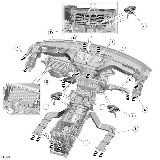
| ITEM | DESCRIPTION |
|---|---|
| 1 | Center front face vents |
| 2 | Duct air temperature sensor - center front face |
| 3 | Demist duct (2 off) |
| 4 | Demist vent (2 off) |
| 5 | Driver foot duct |
| 6 | Outer front face vent (2 off) |
| 7 | Duct air temperature sensor - right front foot, rear foot and rear face |
| 8 | Rear foot duct (2 off) |
| 9 | Rear face duct (2 off) |
| 10 | Rear face vents |
| 11 | Duct air temperature sensor - left front foot, rear foot and rear face |
| 12 | Front passenger foot duct |
| 13 | Air filter |
| 14 | Side window vent (2 off) |
| 15 | Outer front face duct (2 off) |
| 16 | Side window duct (2 off) |
The air distribution and filtering system consists of:
- Air ducts
- Air vents
- Air filter.
AIR DUCTS
The air ducts consist of tubes connected between the climate control assembly and the various air vents around the vehicle interior. The center sections of the air ducts for the side window vents are integrated into the structure of the instrument panel. The rear foot ducts connect to the climate control assembly via ducts integrated into the structure of the floor console.
Eight duct air temperature sensors are installed to provide more accurate temperature control. The sensors are installed in the front foot ducts, the center front face ducts and in the rear foot and face ducts. The sensors are NTC Negative Temperature Coefficient) thermistors, which are connected to the HVAC (HVAC Control Module).For additional information, refer to:Control Components (412-01 Climate Control, Description and Operation).
AIR VENTS
Adjustable air vents are installed in the face outlets of the instrument panel and the floor console. The remainder of the outlets have fixed vents integrated into the end of the air duct or installed in the trim panel connected to the air duct.
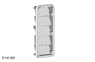
AIR FILTER
The air filter is a combination pollen and odor filter installed in the air inlet duct, over the blower inlet.
CLIMATE CONTROL
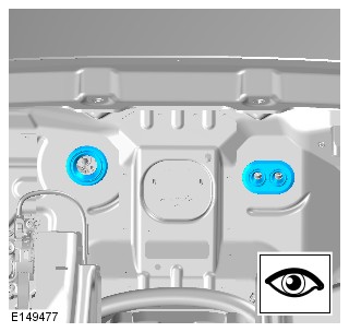
HEATING AND VENTILATION (G2027794)
Right Hand Drive (RHD) vehicle is shown. The Left Hand Drive (LHD) vehicle is similar.
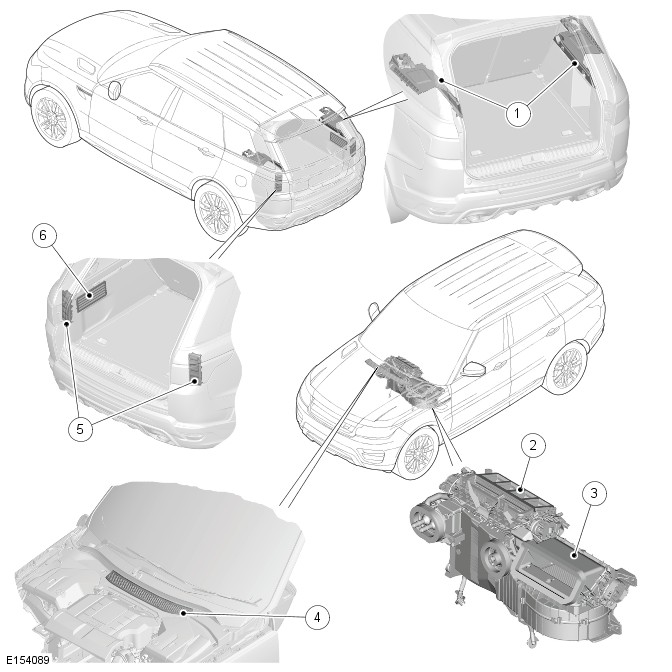
| ITEM | DESCRIPTION |
|---|---|
| 1 | Upper ventilation outlets - Left and right (luggage compartment) |
| 2 | Air outlets from climate control assembly |
| 3 | Fresh air intake to the climate control assembly |
| 4 | Air intake duct |
| 5 | Rear ventilation outlets |
| 6 | Side ventilation outlet (luggage compartment) |
The heating and ventilation system consists of:
- An air intake panel
- A climate control assembly with air inlet and outlets
- Ventilation outlets.
Fresh or recirculated air flows into the heater assembly from the intake duct. The blower, and ram effect when the vehicle is moving, forces the air through the heater assembly. Air from the vehicle interior exhausts through the ventilation outlets.
AIR INTAKE PANEL
The air intake panel is attached to the front of the bulkhead panel, around the fresh air intake for the air intake duct.
AIR INTAKE DUCT
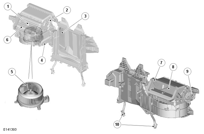
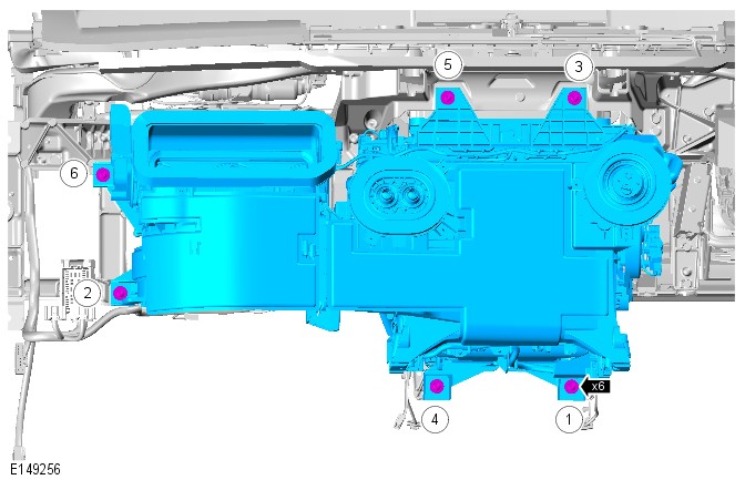
| ITEM | DESCRIPTION |
|---|---|
| 1 | Recirculation air intake |
| 2 | Pollution sensor |
| 3 | Air outlet to heater |
| 4 | HVAC Control Module |
| 5 | Blower |
| 6 | Recirculation door |
| 7 | Fresh air intake |
| 8 | Air filter |
| 9 | Recirculation motor |
| 10 | Evaporator drain tubes |
The air intake duct is installed behind the instrument panel, on the front passenger side, and connects the fresh air intake in the bulkhead panel to the heater. The air intake duct also contains:
- An intake for recirculation air
- The blower
- The air filter.
A recirculation door is installed between the fresh and recirculation air intakes, to control the source of incoming air. The recirculation door is driven by a recirculation motor, which is controlled by the HVAC Control Module using a Local Interconnect Network (LIN) bus signal. Power for the motor is also supplied by the HVAC Control Module.
The recirculation door has automatic and manual modes of operation. In the automatic mode the HVAC Control Module uses comfort algorithms and the pollution sensor input to set the door position. In the manual mode, the HVAC Control Module sets the door to the position selected on the Integrated Control Panel (ICP).
BLOWER
The blower is installed below the air filter, and consists of an open hub, centrifugal fan powered by an electric motor. Operation of the blower is controlled by the HVAC Control Module, using the blower relay in the RJB (Rear Junction Box) and a control module integrated into the blower motor.
When the blower is required, the HVAC energizes the blower relay, which then supplies battery power to the blower motor. The speed of the blower is controlled by the integral control module, which regulates the blower motor voltage in response to a PWM (Pulse Width Modulation) signal from the HVAC.
When the blower is in the automatic mode the HVAC determines the blower speed required from comfort algorithms. When the blower is in the manual mode, the HVAC operates the blower at the speed selected on the ICP.
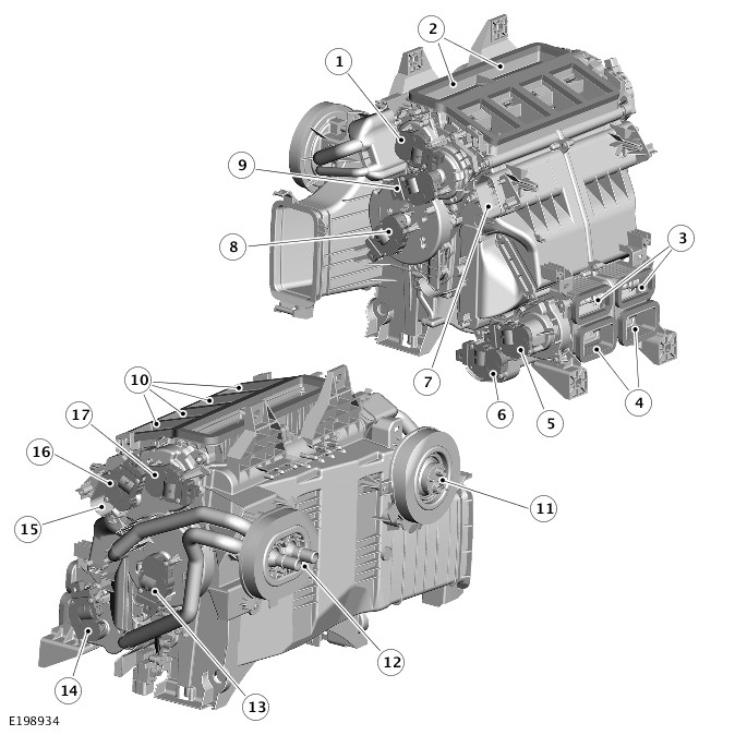
HEATER
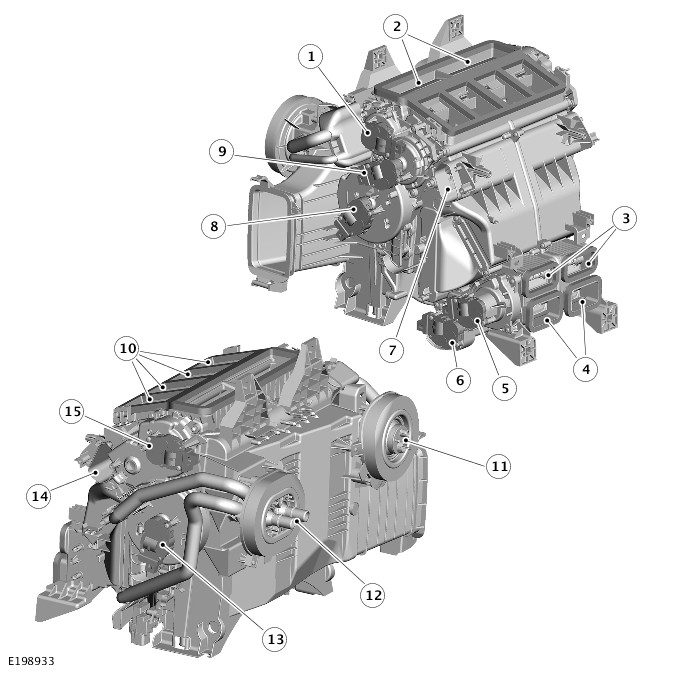
| ITEM | DESCRIPTION |
|---|---|
| 1 | Demist distribution motor |
| 2 | Demist air outlets |
| 3 | Rear foot air outlets |
| 4 | Rear face air outlets |
| 5 | Rear face/foot distribution motor |
| 6 | Rear left temperature blend motor |
| 7 | Front left foot air outlet |
| 8 | Front left temperature blend motor |
| 9 | Front let face/foot distribution motor |
| 10 | Front face air outlets |
| 11 | Air conditioning pipe connector block |
| 12 | Coolant pipe connections |
| 13 | Front right temperature blend motor |
| 14 | Rear right temperature blend motor |
| 15 | Front right foot air outlet |
| 16 | Front right face/foot distribution motor |
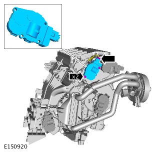
| 17 | Cool air bypass motor |
| ITEM | DESCRIPTION |
|---|---|
| 1 | Demist distribution motor |
| 2 | Demist air outlets |
| 3 | Rear foot air outlets |
| 4 | Rear face air outlets |
| 5 | Rear face/foot distribution motor |
| 6 | Rear left temperature blend motor |
| 7 | Front left foot air outlet |
| 8 | Front left temperature blend motor |
| 9 | Front left face/foot distribution motor |
| 10 | Front face air outlets |
| 11 | Air conditioning pipe connector block |
| 12 | Coolant pipe connections |
| 13 | Front right temperature blend motor |
| 14 | Rear right temperature blend motor |
| 15 | Front right foot air outlet |
| 16 | Front right face/foot distribution motor |
| 17 | Cool air bypass motor |
The heater is installed on the vehicle center-line, between the instrument panel and the bulkhead panel. The heater consists of a casing, which contains an evaporator, heater core, distribution doors and temperature blend doors. Internal passages integrated into the casing guide the air through the casing and separate it into two flows, one for the left outlets and one for the right outlets.
When the Air Conditioning (A/C) system is operating, the evaporator cools the air entering the heater.
The heater core is an aluminum two pass, fin and tube heat exchanger, installed across the width of the heater housing. Two aluminum tubes attached to the heater core extend through the bulkhead panel to connect with the engine cooling system. When the engine is running, coolant is constantly circulated through the heater core by the engine coolant pump. On vehicles with a Fuel Fired Booster Heater (FFBH), when the FFBH is active the coolant flow is assisted by an electric FFBH coolant pump.
The distribution doors direct the air flow to the face, foot and demist vents as required. A cool air bypass distribution door directs additional air around the heater core for the face vents.
The temperature blend doors regulate the flow of air through the heater core to control the temperature of the air leaving the heater. The left front and right front temperature blend doors operate independently to allow different temperatures to be set for front zones. The left rear and right rear temperature blend doors operate together on 3 zone vehicles and independently on 4 zone vehicles.
DISTRIBUTION AND TEMPERATURE BLEND MOTORS
Separate motors operate each of the distribution doors and temperature blend doors. If a motor is to be replaced, make sure it is replaced with the correct replacement part. Although similar in appearance, each of the motors is different and faults will occur if an incorrect motor is fitted.
Operation of the distribution and temperature blend door motors is controlled by the HVAC Control Module. The HVAC is connected to the motors by Local Interconnect Network (LIN) bus, power and ground connections. A Hall effect sensor in each motor provides a position signal for the HVAC.
VENTILATION OUTLETS
The ventilation outlets are installed in the left and right rear quarters, behind the tail lamp assemblies.
Each ventilation outlet consists of a grille covered by soft rubber flaps, and is effectively a non-return valve. The flaps open and close automatically depending on the differential between passenger compartment and outside air pressures.
CLIMATE CONTROL
AIR CONDITIONING (G1950051)
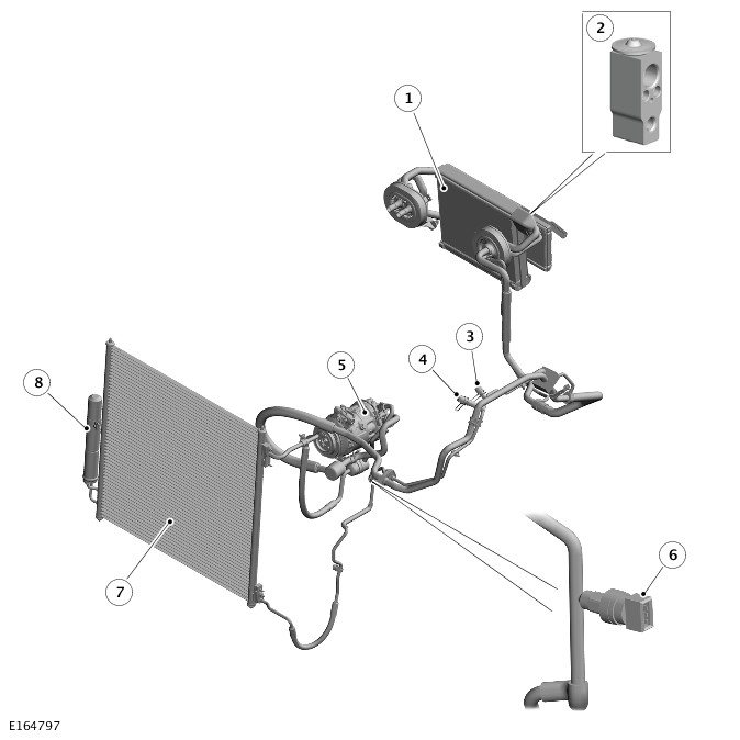
| ITEM | DESCRIPTION |
|---|---|
| 1 | Evaporator |
| 2 | Thermostatic eXpansion Valve (TXV) |
| 3 | Low Pressure (LP) servicing connection |
| 4 | High Pressure (HP) servicing connection |
| 5 | Air conditioning compressor |
| 6 | Refrigerant pressure sensor |
| 7 | Condensor |
| 8 | Receiver drier |
The A/C (Air Conditioning) system is a sealed, closed loop system filled with a charge weight of refrigerant as the heat transfer medium. Depending on market, the refrigerant is either R1234yf or R134a. Oil is added to the refrigerant to lubricate the internal components of the A /C compressor. The system consists of:
- An A/C compressor
- An A/C condensor
- A receiver drier
- A Thermostatic eXpansion Valve (TXV)
- An evaporator
- Low and High Pressure refrigerant lines.
A pressure sensor in the high pressure refrigerant line allows the HVAC (HVAC Control Module) to monitor the status of the A/C system.For additional information, refer to:Control Components (412-01 Climate Control, Description and Operation).
AIR CONDITIONING COMPRESSOR
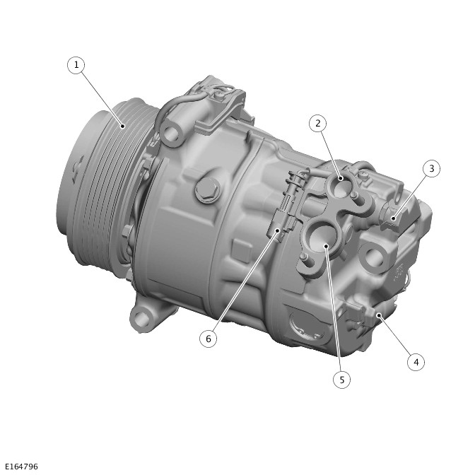
| ITEM | DESCRIPTION |
|---|---|
| 1 | Pulley |
| 2 | Refrigerant outlet port |
| 3 | Pressure relief valve |
| 4 | Electronic control valve |
| 5 | Refrigerant inlet port |
| 6 | Electrical connector |
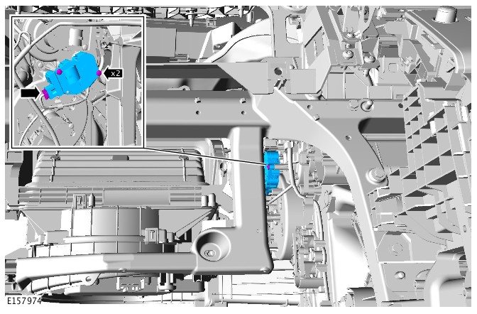
On all engine variants, the A/C compressor is a variable displacement unit attached to the front left side of the engine with three bolts.
The compressor is driven by the engine accessory drive belt via an electro-magnetic clutch in the compressor pulley. The HVAC controls the operation of the electro-magnetic clutch. The clutch incorporates a thermal cut-off fuse, which disconnects the power feed from the HVAC Control Module if the temperature increases to 182 ± 5 °C (360 ± 9 °F).
The displacement of the compressor is controlled by an integral electronic control valve, which is operated by the HVAC Control Module. The HVAC Control Module automatically adjusts the displacement of the A/C compressor, between the minimum and maximum values, to match the thermal load of the evaporator.
To protect the refrigerant system from excessive pressure, a pressure relief valve is installed in the outlet side of the A/C compressor. The pressure relief valve vents excess pressure into the engine compartment.
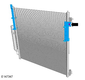
CONDENSOR
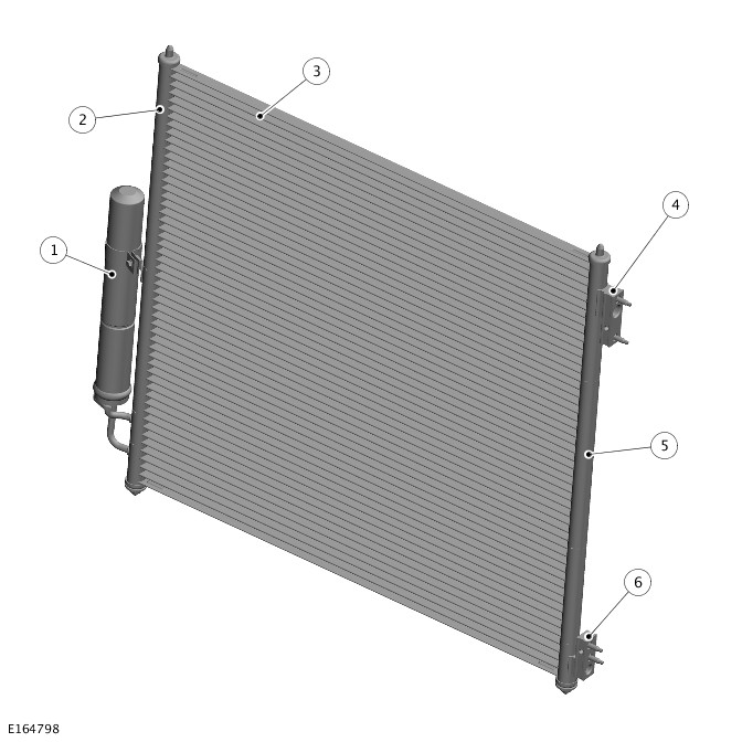
| ITEM | DESCRIPTION |
|---|---|
| 1 | Receiver drier attachment bracket |
| 2 | Refrigerant inlet port |
| 3 | Refrigerant outlet port |
| 4 | Receiver drier pipes |
The condenser is installed immediately in front of the radiator. Pins on the bottom of the end tanks locate in bushes installed in brackets integrated into the bottom of the radiator. Two brackets attach pins on the top of the end tank to pins on the top of the radiator.
The condenser is classified as a sub-cooling condenser and consists of a fin and tube heat exchanger core installed between two end tanks. Divisions in the end tanks separate the heat exchanger into a four pass upper (condensor) section and a two pass lower (sub-cooler) section. Two connector blocks on the left end tank of the condenser provide connections for the high pressure lines from the A/C compressor and the evaporator. Two pipes at the bottom of the right end tank of the condenser provide connections for the receiver drier.
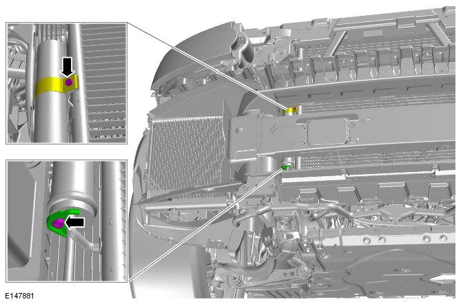
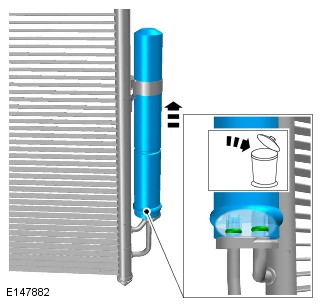
RECEIVER DRIER

The receiver drier is attached to the two stub pipes on the right end tank of the condenser. A collar, located on lands on the stub pipes and secured with a bolt, attaches the stub pipes to the receiver drier. The body of the receiver drier is installed in a bracket welded to the right end tank of the condenser.
The inlet and outlet ports of the receiver drier are the same size, so care must be taken to install the receiver drier the correct way round on the stub pipes. To assist with installation, the inlet port is identified with the word IN etched into the receiver drier.
Refrigerant entering the receiver drier passes through a filter and a desiccant pack, then collects in the base of the unit before flowing through the outlet stub pipe back to the condenser. The desiccant and the filter are non-serviceable; the complete unit must be replaced when a change of desiccant is required.
THERMOSTATIC EXPANSION VALVE (TXV)
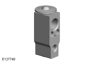
The thermostatic expansion valve is a block type valve attached to the inlet and outlet ports of the evaporator, under a thermal insulation cover.
Two bolts secure the refrigerant pipes and the thermostatic expansion valve to the inlet and outlet ports of the evaporator.
EVAPORATOR
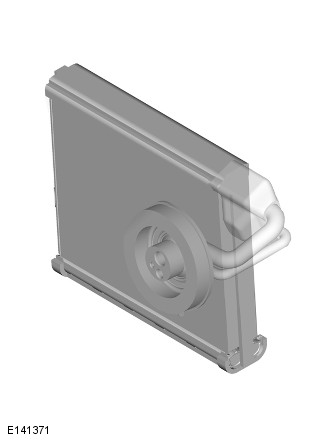
The evaporator is a fin and tube heat exchanger installed in the heater assembly, between the blower and the heater core.
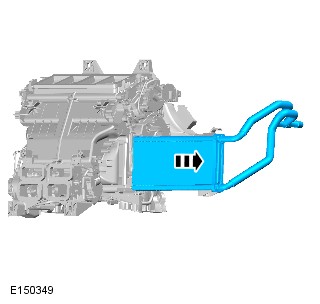
REFRIGERANT LINES
V8 S/C 5.0L Petrol engine installation is shown, other installations are similar.
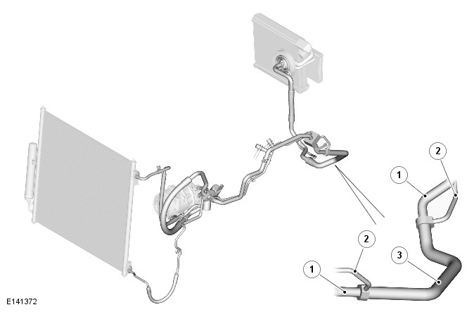
| ITEM | DESCRIPTION |
|---|---|
| 1 | Low pressure pipe |
| 2 | High pressure pipe |
| 3 | Internal heat exchanger |
The refrigerant lines consist of a combination of rigid pipes and flexible hoses that connect the thermostatic expansion valve on the evaporator to the A/C compressor and the condenser. An internal heat exchanger increases the efficiency of the evaporator and ensures any residual liquid in the low pressure line is evaporated before it reaches the compressor.
The internal heat exchanger is incorporated primarily because of the introduction of refrigerant R1234yf (which is less efficient than refrigerant R134a), but is included in all systems for commonality reasons.
Low and high pressure servicing connections are incorporated into the refrigerant lines for system servicing. The high pressure line also incorporates a refrigerant pressure sensor for the climate control system.For additional information, refer to:Control Components (412-01 Climate Control, Description and Operation).
On vehicles with auxiliary climate control, connections for the auxiliary A/C system are incorporated into the refrigerant lines in the left rear corner of the engine compartment.For additional information, refer to:Auxiliary Climate Control (412-02 Auxiliary Climate Control, Description and Operation).
The A/C compressor circulates the refrigerant around the system by compressing low pressure, low temperature vapor from the evaporator and discharging the resultant high pressure, high temperature vapor to the condenser. In the condenser the vapor converts to a liquid, which then passes through the receiver drier and out of the condenser to the thermostatic expansion valve. As it passes through the thermostatic expansion valve, the liquid refrigerant changes to a fine, low pressure, spray, which is directed into the evaporator. In the evaporator the refrigerant changes back to a low pressure, low temperature vapor, as it absorbs heat from the air in the passenger compartment, then returns to the A/C compressor to begin the cycle again.
Operation of the air conditioning system is controlled by the HVAC, which adjust the electronic control valve in the A/C compressor to match the refrigerant flow around the system to the thermal load of the evaporator. By matching refrigerant flow to the thermal load of the evaporator, the HVAC maintains the required temperature in the passenger compartment while maximizing fuel economy.
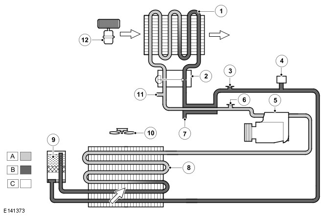
A = REFRIGERANT VAPOR; B = REFRIGERANT LIQUID; C = AIR FLOW.
| ITEM | DESCRIPTION |
|---|---|
| 1 | Evaporator |
| 2 | Thermostatic eXpansion Valve (TXV) |
| 3 | High pressure servicing connection |
| 4 | Refrigerant pressure sensor |
| 5 | Air conditioning (A/C) compressor |
| 6 | Low pressure servicing connection |
| 7 | High pressure connection for auxiliary climate control (where fitted) |
| 8 | Condensor |
| 9 | Receiver drier |
| 10 | Engine cooling fan(s) |
| 11 | Low pressure connection for auxiliary climate control (where fitted) |
| 12 | Blower |
CLIMATE CONTROL
CONTROL COMPONENTS (G1950052)

| ITEM | DESCRIPTION |
|---|---|
| 1 | Pollution sensor |
| 2 | Duct air temperature sensor - Front left face |
| 3 | Duct air temperature sensor - Front right face |
| 4 | Duct air temperature sensor - Front right foot |
| 5 | Duct air temperature sensor - Rear right foot |
| 6 | Duct air temperature sensor - Rear right face |
| 7 | Duct air temperature sensor - Rear left face |
| 8 | Duct air temperature sensor - Rear left foot |
| 9 | Duct air temperature sensor - Front left foot |
| 10 | HVAC Control Module |
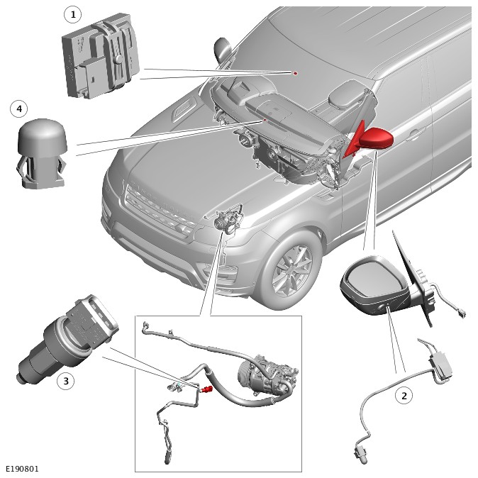
| ITEM | DESCRIPTION |
|---|---|
| 1 | Humidity sensor |
| 2 | Ambient Air Temperature (AAT) sensor |
| 3 | Refrigerant pressure sensor |
| 4 | Sunload sensor - front |
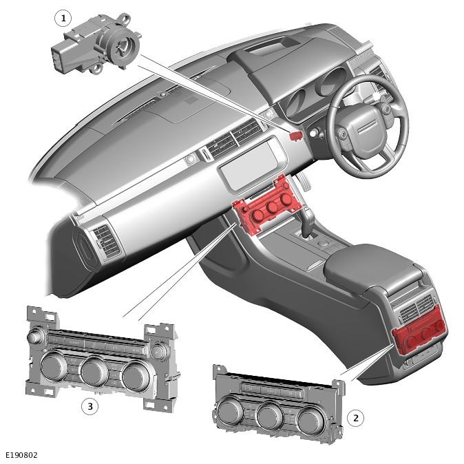
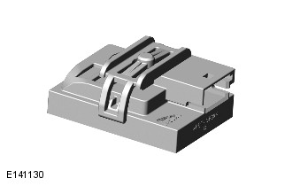
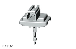
| ITEM | DESCRIPTION |
|---|---|
| 1 | In-vehicle temperature sensor |
| 2 | Front Integrated Control Panel (ICP) |
| 3 | Rear Integrated Control Panel (RICP) |
The standard climate control system operates the Air Conditioning (A/C) system and the heating and ventilation system to control the temperature, volume and distribution of air from the climate control assembly. Operation can be fully automatic, but manual overrides are provided for the intake air source, blower speed and air distribution. The standard climate control system is a three zone system that maintains the individual temperature levels selected for the driver, front passenger and rear seat passenger areas of the vehicle.
Auxiliary climate control (where fitted) provides individual control for the left and right rear seat passenger areas to give a four zone climate control system.For additional information, refer to:Auxiliary Climate Control (412-02 Auxiliary Climate Control, Description and Operation).
The standard climate control system consists of the following components:
- Front Integrated Control Panel (ICP)
- Rear Integrated Control Panel (RICP)
- HVAC Control Module
- Ambient Air Temperature (AAT) sensor
- Refrigerant pressure sensor
- Evaporator temperature sensor
- In-vehicle temperature sensor
- Humidity sensor
- Front and rear sunload sensors
- Pollution sensor
- Duct air temperature sensors.
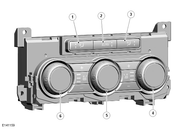
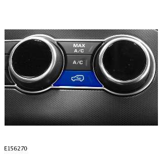
INTEGRATED CONTROL PANEL
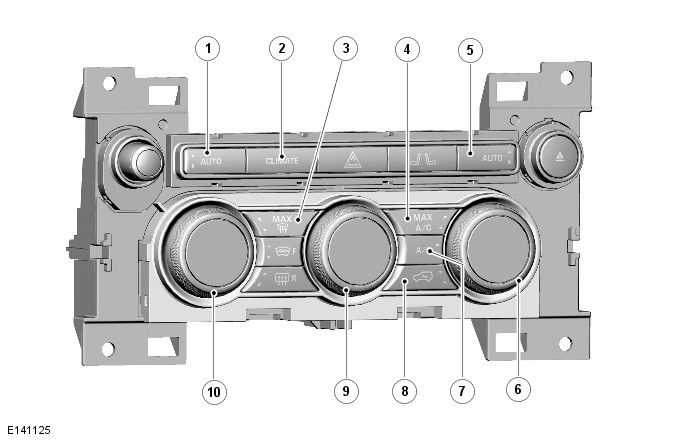
| ITEM | DESCRIPTION |
|---|---|
| 1 | Automatic mode switch - Left |
| 2 | Climate control menu switch |
| 3 | Maximum demist switch |
| 4 | Maximum air conditioning switch |
| 5 | Automatic mode switch - Right |
| 6 | Temperature rotary - Right |
| 7 | Air conditioning system on/off switch |
| 8 | Recirculation switch |
| 9 | Blower switch |
| 10 | Temperature rotary - Left |
The front Integrated Control Panel (ICP) is installed in the center of the instrument panel and contains push switches and rotary switches for operation of the climate control system. The push switches, except the Climate shortcut button and the rotary push, contain an amber status Light Emitting Diode (LED). Display screens are integrated into the center of the rotary switches to display the selected temperature and blower speed as applicable. In addition to the switches for the climate control system, the ICP also contains switches for operation of:
- The audio system.For additional information, refer to:Audio System (415-01 Information and Entertainment System - Vehicles With: InControl Touch Pro, Description and Operation).
- The hazard warning lamps.For additional information, refer to:Exterior Lighting (417-01 Exterior Lighting, Description and Operation).
- The front seat heaters/climate system.For additional information, refer to:Seats (501-10 Seating, Description and Operation).
- The windshield and rear window heaters.For additional information, refer to:Glass, Frames and Mechanisms (501-11 Glass, Frames and Mechanisms, Diagnosis and Testing).
The ICP converts selections on the climate control switches into High Speed (HS) Controller Area Network (CAN) Power Mode Zero messages and transmits them to the HVAC Control Module. The ICP is also on the HS CAN Comfort bus.
REAR INTEGRATED CONTROL PANEL
| ITEM | DESCRIPTION |
|---|---|
| 1 | Foot distribution switch |
| 2 | Automatic mode switch |
| 3 | Face distribution switch |
| 4 | Temperature switch - Right |
| 5 | Blower switch |
| 6 | Temperature switch - Left |
On standard climate control systems the Rear Integrated Control Panel (RICP) is installed in the rear of the floor console. The control panel contains rotary and push button switches for controlling the temperature, volume and distribution of air to the rear seats. Each push switch contains an amber status Light Emitting Diode (LED). Display screens are integrated into the center of the rotary switches to display the selected temperature and blower speed as applicable.
Additional push switches on the RICP are provided for control of seat heating/climate control seats.For additional information, refer to:Seats (501-10 Seating, Description and Operation).
The RICP has a permanent battery power feed from the Passenger Junction Box (PJB), and is connected to the High Speed (HS) Controller Area Network (CAN) comfort bus. The RICP converts selections on the climate control switches into HS CAN comfort messages and transmits them to the Integrated Control Panel (ICP). The ICP transmits the selections to the HVAC Control Module.
The RICP only sends button presses out, and has no logic. The RICP sends the button presses to the ICP, which then chooses the state, and sends it to the HVAC.
HVAC CONTROL MODULE
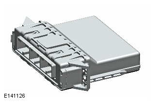
The HVAC Control Module is mounted on the inboard side of the air inlet duct, behind the front passenger side of the instrument panel.
The HVAC processes inputs from the climate control system sensors, the front Integrated Control Panel (ICP), the Touch Screen (TS) and other systems. The HVAC outputs the appropriate control signals to the Air conditioning (A/C) system and the heating and ventilation system. In addition to the A/C system and the heating and ventilation system, the HVAC also controls the following:
- The windshield washer jet heaters and the wiper blade heater.For additional information, refer to:Wipers and Washers (501-16 Wipers and Washers, Description and Operation).
- The front and rear seat heaters (where fitted).For additional information, refer to:Seats (501-10 Seating, Description and Operation).
- Auxiliary climate control system (where fitted).For additional information, refer to:Auxiliary Climate Control (412-02 Auxiliary Climate Control, Description and Operation).
- Fuel Fired Booster Heater (FFBH) (where fitted). For additional information, refer to:Fuel Fired Booster Heater (412-02 Auxiliary Climate Control, Description and Operation).
- Electric booster heater (where fitted).For additional information, refer to:Electric Booster Heater (412-02 Auxiliary Climate Control, Description and Operation).
AMBIENT AIR TEMPERATURE SENSOR
The Ambient Air Temperature (AAT) sensor is a Negative Temperature Coefficient (NTC) thermistor installed in the left exterior rear view mirror. The bulb of the sensor is positioned over a hole in the bottom of the mirror casing.
The Powertrain Control Module (PCM) provides the ambient air temperature sensor with a 5V reference voltage and translates the return signal voltage into a temperature. The PCM transmits the temperature on the High Speed (HS) Controller Area Network (CAN) Powertrain bus and FlexRay for use by other systems. The HVAC receives the temperature on the HS CAN Power Mode Zero bus via the Body Control Module/Gateway Module (BCM/GWM).
REFRIGERANT PRESSURE SENSOR

The refrigerant pressure sensor is located in the high pressure refrigerant line between the condenser and the thermostatic expansion valve.
The HVAC Control Module provides a 5V reference voltage to the refrigerant pressure sensor and receives a return signal voltage related to system pressure.
The HVAC uses the signal from the refrigerant pressure sensor to protect the refrigerant system from extremes of pressure and to calculate the Air Conditioning (A/C) compressor load on the engine. The HVAC transmits the A/C compressor load value to the PCM, via the High Speed (HS) Controller Area Network (CAN) Power Mode Zero bus, Body Control Module/Gateway Module (BCM/GWM) and HS CAN Powertrain bus, for use in controlling the speed of the engine cooling fan.
To protect the system from extremes of pressure, the HVAC will disengage the clutch to switch off the A/C compressor, if the pressure:
- Decreases to 1.9 ± 0.2 bar (27.5 ± 3 lbf/in²); the HVAC loads the A/C compressor again when the pressure increases to 2.8 ± 0.2 bar (40.5 ± 3 lbf/in²).
- Increases to 33 ± 1 bar (479 ± 14.5 lbf/in²); the HVAC loads the A/C compressor again when the pressure decreases to 23.5 ± 1 bar (341 ± 14.5 lbf/in²).
If the evaporator is faulty the A/C compressor is disengaged.
EVAPORATOR TEMPERATURE SENSOR
The evaporator temperature sensor is a Negative Temperature Coefficient (NTC) thermistor that provides the HVAC Control Module with a temperature signal from the air outlet side of the evaporator. The sensor extends into the air flow on the downstream side of the evaporator.
The HVAC uses the input from the evaporator temperature sensor to control the load of the A/C compressor, and thus the operating temperature of the evaporator.
The HVAC provides the evaporator temperature sensor with a 5V reference voltage and translates the return signal voltage into a temperature. If the sensor develops a fault, the HVAC will disengage the clutch to switch off the A/C compressor.
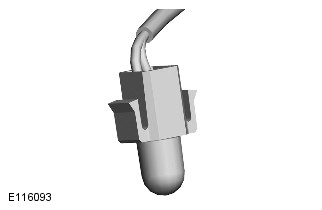
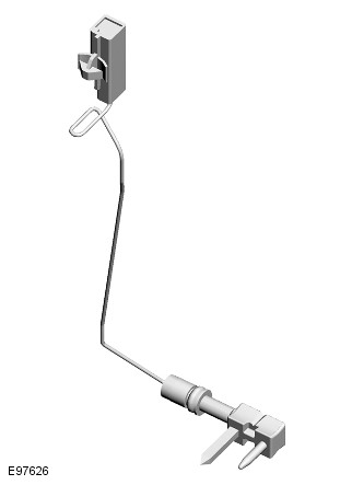
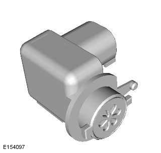
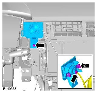
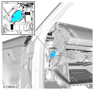
IN-VEHICLE TEMPERATURE SENSOR

The in-vehicle temperature sensor is a Negative Temperature Coefficient (NTC) thermistor installed behind a grill in the instrument panel, on the inboard side of the steering column. A motor driven fan in the sensor draws air through the grill and over the thermistor.
The HVAC Control Module uses the signal from the in-vehicle temperature sensor for control of the climate control assembly output temperatures, blower speed and air distribution.
The HVAC provides the in-vehicle temperature sensor with a 5v reference voltage and translates the return signal voltage into a temperature. If the in-vehicle temperature sensor develops a fault, the HVAC adopts a default temperature of 20 °C (68 °F).
HUMIDITY SENSOR
The humidity sensor is installed in a bracket attached to the inside of the windshield, to the right of the interior mirror. The sensor is concealed under a cover, which clips onto the bracket. The sensor comprises three individual elements:
- A capacitive humidity sensor
- A Negative Temperature Coefficient (NTC) thermistor air temperature sensor
- A windshield glass temperature sensor.
SUNLOAD SENSOR

The front sunload sensor is installed in the top of the instrument panel, in the center demist grille.
The HVAC Control Module provides the sunload sensor with a 5v reference voltage. The sensor contains photoelectric cells that provide the HVAC with two inputs of light intensity, which equates to the solar heating effect on the left and right sides of the vehicle.
The HVAC Control Module compensates for the solar heating effect by adjusting blower speed, climate control assembly output temperature and air distribution to maintain the required zone temperatures.
POLLUTION SENSOR
The pollution sensor is mounted on the inboard side of the air inlet duct, in the fresh air inlet.
The pollution sensor has battery power, ground and signal connections with the HVAC Control Module module. Semiconductor material in the sensor undergoes a change of conductance if exposed to specific gases. The sensor uses this property to monitor for gases such as Carbon Monoxide (CO) and Nitrogen Oxides (NOx) and so determine the quality of the fresh air entering the vehicle. The sensor transmits the air quality to the HVAC, in a Pulse Width Modulation (PWM) signal, as one of the following four conditions:
- Static or reduced pollution levels
- Small increase in pollution levels
- Medium increase in pollution levels
- Rapid or large increase in pollution levels.
Based on the signal from the pollution sensor, the HVAC controls the intake air source to reduce the amount of contaminants entering the interior. It is possible to put the system into recirculation via the switch but it is not possible to select fresh air. The pollution sensor may be turned off via the climate settings on the touch screen.
DUCT AIR TEMPERATURE SENSORS
The duct air temperature sensors are Negative Temperature Coefficient (NTC) thermistors installed in the following distribution ducts:
- Left and right center front face ducts
- Left and right front foot ducts
- Left and right second row foot ducts
- Left and right second row face ducts
The duct air temperature sensors are provided with 5V reference signal and ground connections with the HVAC Control Module. The HVAC uses the sensor inputs in the calculations used to set the temperatures of the air leaving the climate control assembly.
In Power Mode 7, the standard climate control system can be activated using the AUTO switches on the Integrated Control Panel (ICP), or the AUTO soft keys on the Front climate or Rear climate menus of the touch screen. Provided the rear climate control panel is unlocked (on the Touch Screen (TS) Rear climate menu), pressing the AUTO switch on the rear ICP will also activate the system.
INTAKE AIR CONTROL
The source of inlet air is automatically controlled by the HVAC Control Module, unless overridden by pressing the recirculation switch on the front Integrated Control Panel (ICP) to give timed or latched recirculation. A brief press of the switch illuminates the switch indicator and activates timed recirculation. There is also a pop up on the touch screen informing the user if the system has entered latched or timed recirculation. Pressing and holding the switch causes the switch indicator to flash and then illuminate constantly, indicating that the air inlet is in latched recirculation and the switch can be released. A second press of the switch cancels recirculation and the HVAC returns the recirculation door to the fresh air position. Timed recirculation is automatically cancelled after a set time, which varies with ambient air temperature.
During automatic control, the HVAC determines the required position of the recirculation door from comfort algorithms and the pollution sensor. The HVAC is looking for spikes in pollution and attempts to stop the spikes entering the vehicle.
The sensitivity of the pollution sensor can be adjusted on the Touch Screen (TS), using the Settings soft key of the Front climate menu. The pollution sensing function can also be switched off by adjusting sensitivity to the minimum setting. If there is a fault with the pollution sensor, the HVAC disables automatic operation of the recirculation door due to the pollution sensor. The HVAC shall continue automatic operation of the recirculation door due to the comfort algorithms.
AIR TEMPERATURE CONTROL
The HVAC Control Module calculates the temperature blend motor positions required to achieve the selected temperature and compares it against the current position. If there is any difference, the HVAC signals the motors to adopt the new position.
Air temperature is controlled automatically unless maximum heating (HI) or maximum cooling (LO) is selected. When maximum heating or cooling is selected, a comfort algorithm in the HVAC adopts an appropriate strategy for air distribution, blower speed, and air source.
Temperature control in one zone can be compromised by another zone being set to a high level of heating or cooling. True maximum heating or cooling (displayed as HI or LO on the Touch Screen (TS) and switches) can only be selected for the driver zone. If HI or LO is selected for the driver zone, the temperature for the other zones is automatically set to match the driver zone.
If A/C is selected off in the automatic mode, no cooling of the inlet air will take place. The minimum output air temperature from the system will be ambient air temperature plus any heat pick up in the air inlet path.
If the Sync soft key on the TS Front climate menu is pressed, the HVAC synchronizes the temperature of the other zones with the driver zone temperature.
BLOWER CONTROL
When the system is in the automatic mode, the HVAC Control Module determines the blower speed required from a comfort algorithm. When the system is in the manual mode, the HVAC operates the blower at the speed selected on the front Integrated Control Panel (ICP) or Touch Screen (TS). The HVAC also adjusts blower speed to compensate for the ram effect on inlet air produced by forward movement of the vehicle. As vehicle speed and ram effect increases, blower motor speed is reduced, and vice versa.
The blower switch on the Rear Integrated Control Panel (RICP) has no control over the blower in the climate control assembly. Instead, the HVAC adjusts the rear distribution doors to increase the air flow through the rear distribution ducts from the climate control assembly.
The RICP controls the blower of the auxiliary climate control unit. (if fitted)
On a 3 zone configuration, changing the blower speed using the RICP will change the front blower speed. On a 4 zone configuration changing the blower speed using the RICP will change the rear blower speed only.
AIR DISTRIBUTION CONTROL
When the Air Conditioning (A/C) system is in automatic mode, the HVAC Control Module automatically controls air distribution into the passenger compartment in line with its comfort algorithm. Automatic control is overridden by distribution selections on the Touch Screen (TS), the front Integrated Control Panel (ICP) or the Rear Integrated Control Panel (RICP). Air distribution remains as selected until one of the AUTO is selected or a different manual selection is made.
AIR CONDITIONING COMPRESSOR CONTROL
When Air Conditioning (A/C) is selected the HVAC Control Module maintains the evaporator at an operating temperature that varies with the passenger compartment cooling requirements. If the requirement for cooled air decreases, the HVAC Control Module raises the evaporator operating temperature by reducing the flow of refrigerant provided by the A/C compressor. The HVAC closely controls the rate of temperature increase to avoid introducing moisture into the passenger compartment.
If the requirement for cooled air increases, the HVAC lowers the evaporator operating temperature by increasing the flow of refrigerant provided by the A/C compressor.
When A/C is off, the compressor current signal supplied by the HVAC holds the A/C compressor control valve in the minimum flow position and disengages the clutch to switch off the A/C function.
The HVAC incorporates limits for the operating pressure of the refrigerant system. If the system approaches the high pressure limit, the compressor current signal is progressively reduced until the system pressure decreases. If the system falls below the low pressure limit, the compressor current signal is held at its lowest setting so that the A/C compressor is maintained at its minimum stroke. This avoids depletion of the lubricant from the A/C compressor.
AIR CONDITIONING COMPRESSOR TORQUE
The HVAC Control Module transmits refrigerant pressure and Air Conditioning (A/C) compressor current values on the High Speed (HS) Controller Area Network (CAN) Power Mode Zero bus, then through the Body Control Module/Gateway Module (BCM/GWM) onto the HS CAN Powertrain bus to the Powertrain Control Module (PCM). The PCM uses these values to calculate the torque being used to drive the Air Conditioning (A/C) compressor. The PCM compares the calculated value with its allowable value and, if necessary, forces the HVAC to inhibit the A/C compressor by transmitting the 'ACClutchInhibit' CAN message. This forces the HVAC to disengage the clutch to switch off the A/C compressor. This in turn removes the load on the engine required to drive the A/C compressor.
By reducing the maximum A/C compressor torque, the PCM is able to reduce the load on the engine when it needs to maintain vehicle performance or cooling system integrity.
COOLING FAN CONTROL
The HVAC Control Module determines the amount of condenser cooling required from the refrigerant pressure sensor, since there is a direct relationship between the temperature and pressure of the refrigerant. The cooling requirement is broadcast on the High Speed (HS) Controller Area Network (CAN) Power Mode Zero bus. This message is transmitted through the Body Control Module/Gateway Module (BCM/GWM), onto the HS CAN Powertrain bus to the Powertrain Control Module (PCM). The PCM then controls the temperature of the condenser using the cooling fan(s).
MAXIMUM DEMIST
When the MAX demist switch on the Integrated Control Panel (ICP) is pressed, the HVAC Control Module configures the climate control system as follows:
- Automatic mode off.
- Air Conditioning (A/C) on.
- Selected temperature unchanged.
- Air inlet set to fresh air.
- Air distribution set to windshield.
- Blower speed set to high speed.
The HVAC also sends a High Speed (HS) Controller Area Network (CAN) Power Mode Zero bus message through the Body Control Module/Gateway Module (BCM/GWM) to activate the windshield and rear window heaters.
The programmed demist function can be cancelled by one of the following:
- A second press of the MAX demist switch.
- Selecting any air distribution soft key on the touch screen.
- Pressing the driver side AUTO switch on the ICP.
- Switching the ignition OFF.
The blower speed can be adjusted without terminating the programmed demist function. If the blower speed has been adjusted and then the MAX demist switch is pressed again, the system will go back to the MAX demist default settings. If the MAX demist program is cancelled with the MAX demist switch or the driver side AUTO switch, the windshield and rear window heaters remain on until they time out.
CONTROL DIAGRAM
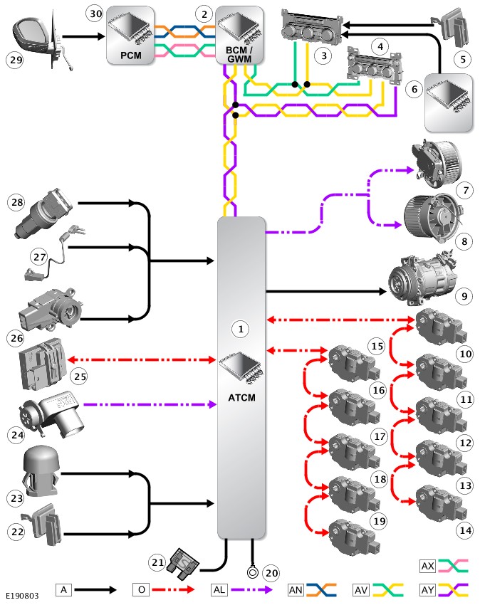
A = HARDWIRED; O = LOCAL INTERCONNECT NETWORK (LIN) BUS; AL = PULSE WIDTH MODULATION (PWM); AN = HIGH SPEED (HS) CONTROLLER AREA NETWORK (CAN) POWERTRAIN BUS; AV = HS CAN COMFORT BUS; AY = HS CAN POWER MODE ZERO; AX = FLEXRAY
| ITEM | DESCRIPTION |
|---|---|
| 1 | HVAC Control Module |
| 2 | Body Control Module/Gateway Module (BCM/GWM) |
| 3 | Rear Integrated Control Panel (RICP) |
| 4 | Front Integrated Control Panel (ICP) |
| 5 | Duct air temperature (4 off) |
| 6 | Auxiliary evaporator temperature sensor |
| 7 | Blower motor - Front |
| 8 | Blower motor - Rear |
| 9 | Air conditioning (A/C) compressor clutch |
| 10 | Blend motor - Front |
| 11 | Blend motor - Front |
| 12 | Blend motor - Front |
| 13 | Blend motor - Front |
| 14 | Blend motor - Front |
| 15 | Blend motor - Rear |
| 16 | Blend motor - Rear |
| 17 | Blend motor - Rear |
| 18 | Blend motor - Rear |
| 19 | Blend motor - Rear |
| 20 | Ground |
| 21 | Supply |
| 22 | Duct air temperature (8 off) |
| 23 | Sunload sensor - Front |
| 24 | Pollution sensor |
| 25 | Humidity sensor |
| 26 | In-vehicle temperature sensor |
| 27 | Evaporator temperature sensor |
| 28 | Refrigerant pressure sensor |
| 29 | Ambient Air Temperature (AAT) sensor |
| 30 | Powertrain Control Module (PCM) |
Removal and Installation
CLIMATE CONTROL
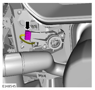
BLOWER MOTOR (G1618352)
- 82.25.33
- BLOWER - RENEW
- ALL DERIVATIVES
- 0.10
- USED WITHINS
-
Removal steps in this procedure may contain installation details.
-
Right Hand illustration shown, Left Hand is similar.
- Disconnect the battery ground cable.
Refer to:Specifications (414-00 Battery and Charging System - General Information, Specifications).
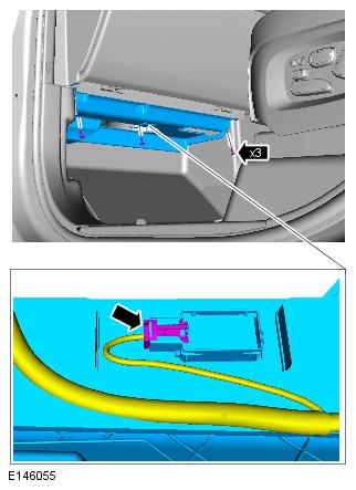
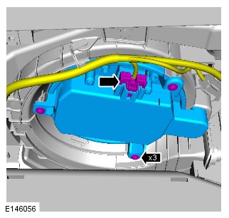
- To install, reverse the removal procedure.
CLIMATE CONTROL
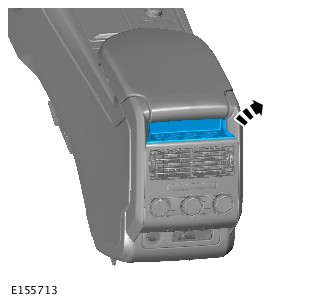
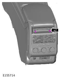
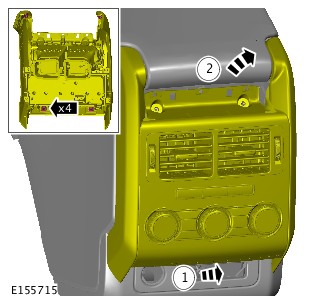
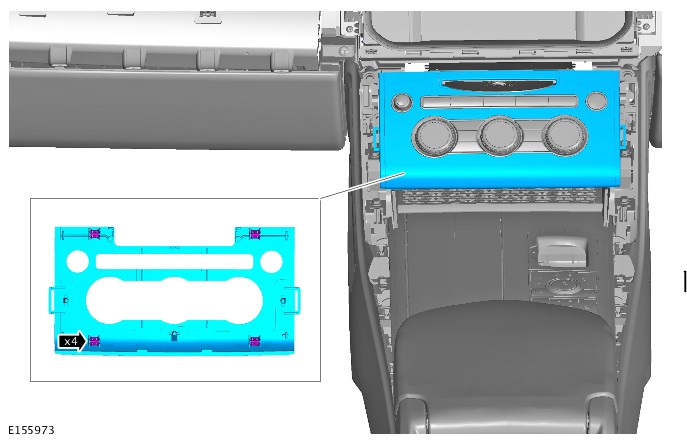
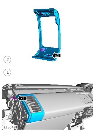
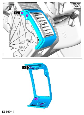
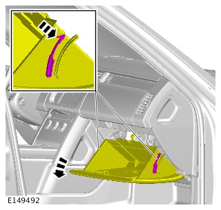
CENTER REGISTERS (G1618353)
- 80.15.24
- VENTILATOR(S) - CENTRE - RENEW
- ALL DERIVATIVES
- 0.60
- USED WITHINS
-
Removal steps in this procedure may contain installation details.
-
Some variation in the illustrations may occur, but the essential information is always correct.
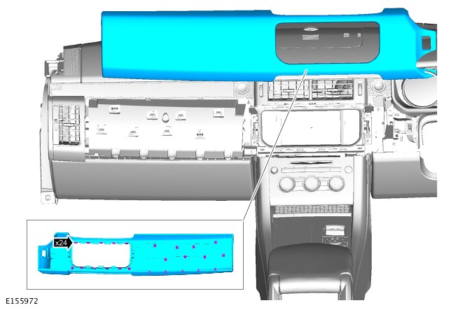
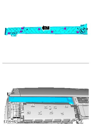
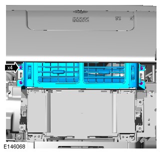
- To install, reverse the removal procedure.
CLIMATE CONTROL
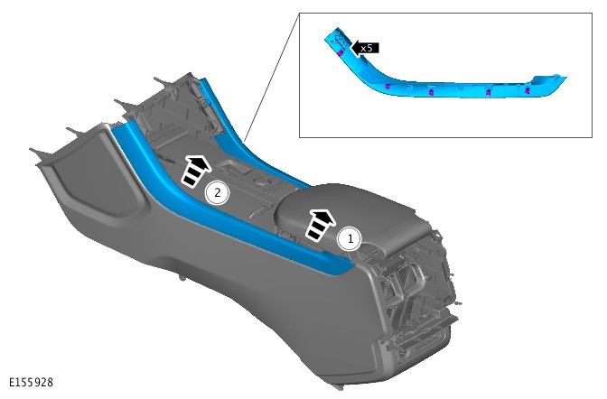
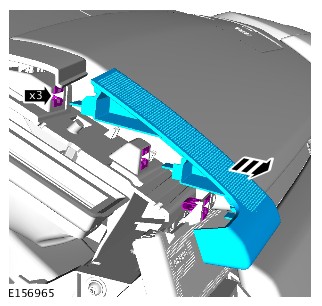
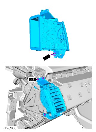
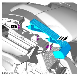
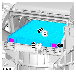
CENTER VENT (G1957725)
- 80.15.24
- VENTILATOR(S) - CENTRE - RENEW
- ALL DERIVATIVES
- 0.60
- USED WITHINS
Removal steps in this procedure may contain installation details.
- Disconnect the battery ground cable.
Refer to:Specifications (414-00 Battery and Charging System - General Information, Specifications).

- To install, reverse the removal procedure.
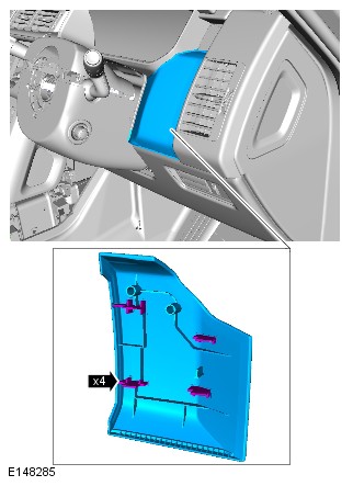
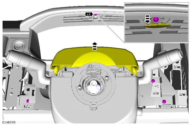
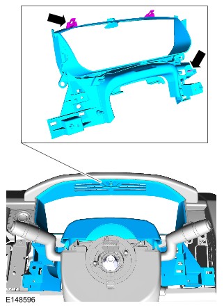
CLIMATE CONTROL
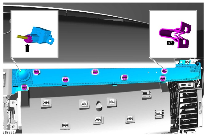
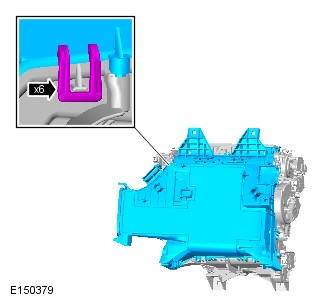
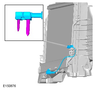
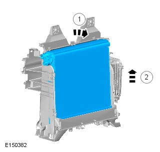
CLIMATE CONTROL ASSEMBLY (G1605566)
- 80.10.02
- CONTROLS - HEATER - RENEW
- ALL DERIVATIVES
- 0.40
- USED WITHINS
-
Removal steps in this procedure may contain installation details.
-
Some components shown removed for clarity.
-
Some variation in the illustrations may occur, but the essential information is always correct.
- Disconnect the battery ground cable.
Refer to:Specifications (414-00 Battery and Charging System - General Information, Specifications).


- To install, reverse the removal procedure.
CLIMATE CONTROL
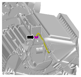
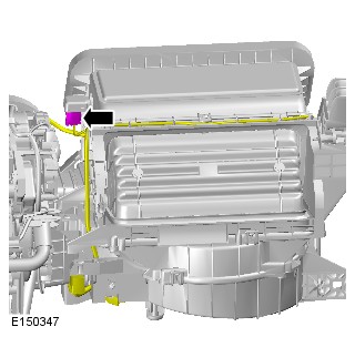
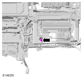
THERMOSTATIC EXPANSION VALVE (G1618354)
- 82.25.01
- VALVE - THERMOSTATIC EXPANSION (TXV) - RENEW
- 3000 CC, TDV6
- 5.80
- USED WITHINS
PART(S)
| STEP | PART NAME | QUANTITY |
|---|---|---|
| Removal Step 5 | Thermostatic expansion valve O-ring seal kit | 1 |
-
Removal steps in this procedure may contain installation details.
-
Some variation in the illustrations may occur, but the essential information is always correct.
-
Refer to:Heater Core and Evaporator Housing (412-01 Climate Control - SDV6 3.0L Diesel - Hybrid Electric Vehicle, Removal and Installation).

- To install, reverse the removal procedure.
CLIMATE CONTROL
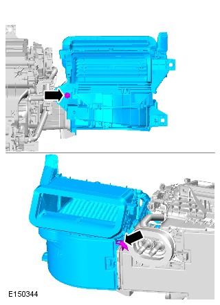
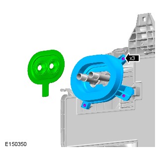
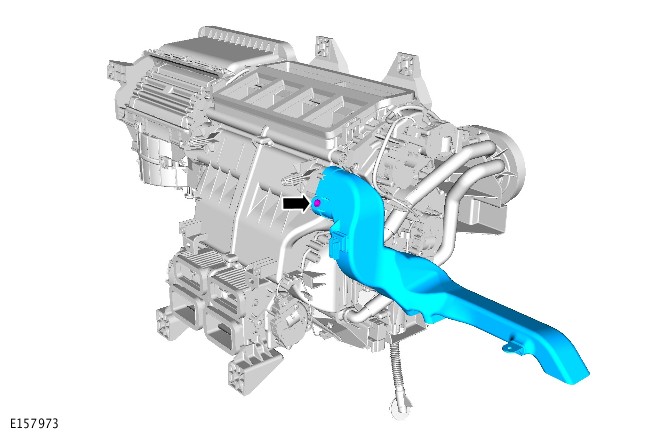
EVAPORATOR (G1618355)
- 82.25.20
- EVAPORATOR - RENEW
- 3000 CC, TDV6
- 6.20
- USED WITHINS
PART(S)
| STEP | PART NAME | QUANTITY |
|---|---|---|
| Removal Step 7 | Thermostatic expansion valve O-ring seal(s) | 1 |
| Removal Step 8 | Thermostatic expansion valve O-ring seal(s) | 1 |
-
Removal steps in this procedure may contain installation details.
-
Some variation in the illustrations may occur, but the essential information is always correct.
-
Raise and support the vehicle.WARNING:
Make sure to support the vehicle with axle stands.
- Disconnect the battery ground cable.
Refer to:Specifications (414-00 Battery and Charging System - General Information, Specifications).
-
Refer to:Heater Core (412-01 Climate Control, Removal and Installation).
- To install, reverse the removal procedure.
CLIMATE CONTROL
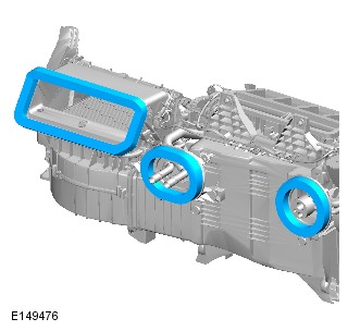
HEATER CORE (G1618356)
- 82.25.19
- MATRIX - HEATER - RENEW
- 3000 CC, TDV6
- 5.80
- USED WITHINS
-
Removal steps in this procedure may contain installation details.
-
Some variation in the illustrations may occur, but the essential information is always correct.
-
Raise and support the vehicle.WARNING:
Make sure to support the vehicle with axle stands.
- Disconnect the battery ground cable.
Refer to:Specifications (414-00 Battery and Charging System - General Information, Specifications).
-
Refer to:Heater Core and Evaporator Housing (412-01, Removal and Installation).

- To install, reverse the removal procedure.
LIMATE CONTROL
CONDENSER - TDV6 3.0L DIESEL /TDV6 3.0L DIESEL - GEN 1.5/TDV6 3.0L DIESEL - GEN 2 (G1509818)
- 82.15.07
- CONDENSER - RENEW
- 3000 CC, TDV6, DIESEL, IC
- 2.80
- USED WITHINS
Removal steps in this procedure may contain installation details.
-
Refer to:Radiator (303-03A Engine Cooling - TDV6 3.0L Diesel /TDV6 3.0L Diesel - Gen 1.5/TDV6 3.0L Diesel - Gen 2, Removal and Installation).
- To install reverse the removal procedure.
CLIMATE CONTROL
CONDENSER (G1957921)
- 82.15.07
- CONDENSER - RENEW
- 3000 CC, TDV6, DIESEL, IC
- 2.80
- USED WITHINS
Make sure that all openings are sealed. Use new blanking caps.
-
This procedure contains some variation in the illustrations depending on the vehicle specification, but the essential information is always correct.
-
This procedure contains illustrations showing certain components removed to provide extra clarity.
- Disconnect the startup battery ground cable.
Refer to:Specifications (414-01 Battery, Mounting and Cables, Specifications).
- Raise and support the vehicle on a suitable 2 post lift.
Refer to:Lifting (100-02 Jacking and Lifting, Description and Operation).
- Remove the radiator.
Refer to:Radiator (303-03G Engine Cooling - INGENIUM I4 2.0L Diesel, Removal and Installation).
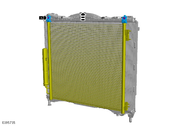
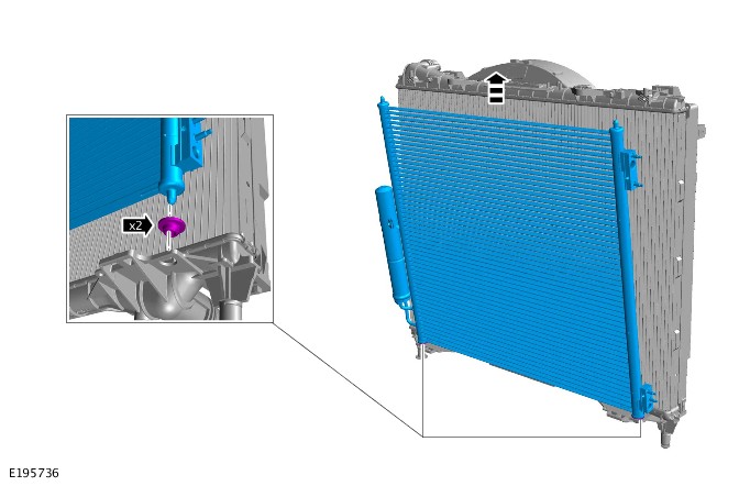
- Install the condenser.
Torque: 4.5Nm
- Install the radiator.
Refer to:Radiator (303-03G Engine Cooling - INGENIUM I4 2.0L Diesel, Removal and Installation).
- Connect the startup battery ground cable.
Refer to:Specifications (414-01 Battery, Mounting and Cables, Specifications).
CLIMATE CONTROL
AMBIENT AIR TEMPERATURE SENSOR (G1618357)
- 80.40.31
- SENSOR - OUTSIDE TEMPERATURE - RENEW
- ALL DERIVATIVES
- 0.40
- USED WITHINS
Removal steps in this procedure may contain installation details.
- Disconnect the battery ground cable.
Refer to:Specifications (414-00 Battery and Charging System - General Information, Specifications).
- The ambient air temperature sensor is an integral part of the door mirror and cannot be removed. A new door mirror must be installed.
Refer to:Exterior Mirror (501-09 Rear View Mirrors, Removal and Installation).
- To install, reverse the removal procedure.
CLIMATE CONTROL
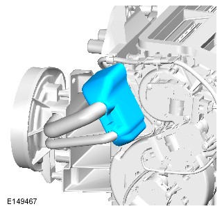
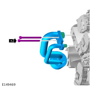
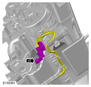
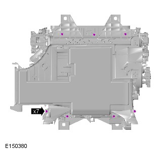
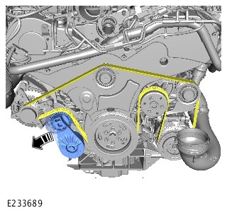
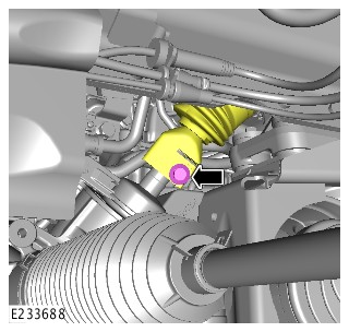
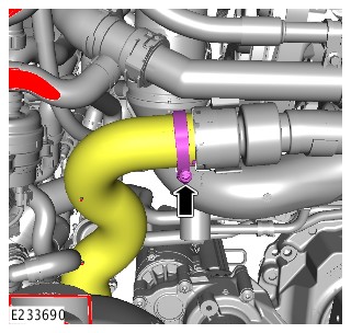
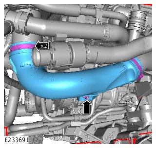
AIR CONDITIONING COMPRESSOR - TDV6 3.0L DIESEL /TDV6 3.0L DIESEL - GEN 1.5/TDV6 3.0L DIESEL - GEN 2 (G1606534)
- 82.10.20
- AIR CONDITIONING (A/C) COMPRESSOR - RENEW
- 3000 CC, TDV6, DIESEL, IC
- 2.80
- USED WITHINS
PART(S)
| STEP | PART NAME | QUALIFICATION | QUANTITY |
|---|---|---|---|
| Step 2 | Air conditioning pipes O-ring seals | All vehicles | 1 |
| Step 11 | Steering column lower shaft lower bolt | Left hand drive vehicles | 1 |
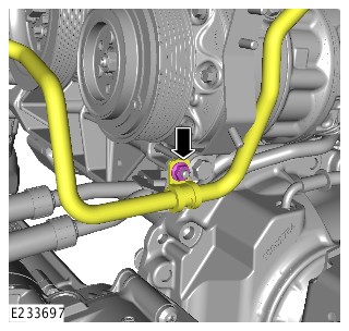
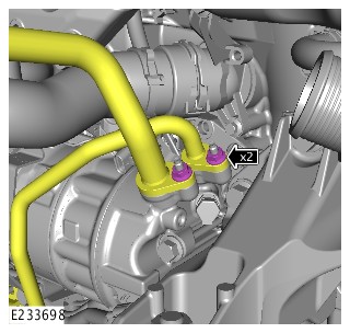
Before disconnecting any components, make sure the area is clean and free from foreign material. When disconnected, all openings must be sealed.
-
This procedure contains some variation in the illustrations depending on the vehicle specification, but the essential information is always correct.
-
This procedure contains illustrations showing certain components removed to provide extra clarity.
- Disconnect the startup battery ground cable.
Refer to:Specifications (414-00 Battery and Charging System - General Information, Specifications).
- Recover the Air Conditioning (A/C) refrigerant.
Refer to:Air Conditioning System Recovery, Evacuation and Charging (412-00 Climate Control System - General Information, General Procedures).
- Remove the left Exhaust Gas Recirculation (EGR) valve.
Refer to:Left Exhaust Gas Recirculation Valve - TDV6 3.0L Diesel - Gen 2 (303-08A Engine Emission Control - TDV6 3.0L Diesel /TDV6 3.0L Diesel - Gen 1.5/TDV6 3.0L Diesel - Gen 2, Removal and Installation).
- Remove the front left wheel arch liner.
Refer to:Fender Splash Shield (501-02 Front End Body Panels, Removal and Installation).

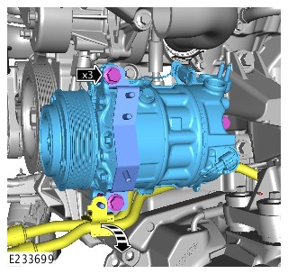
-
- Install the A/C compressor.
- Install and tighten the 3 bolts.
Torque: 25Nm
- Install the transmission fluid cooler pipes.
-
- Connect the electrical connector.
- Secure the electrical wiring harness clip.
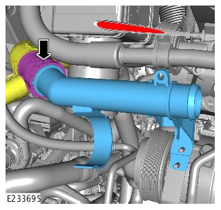
-
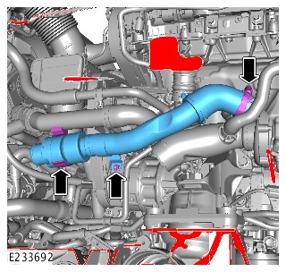
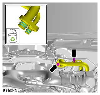
- Install the turbocharger low pressure pipe.
- Secure the hose clip.
-
- Install the turbocharger high pressure pipe.
- Secure the pipe clip.
- Install and tighten the nut.
Torque: 10Nm
- Tighten the hose clamp.
Torque: 5Nm
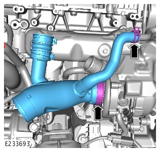
-
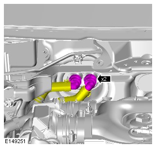
- Install the turbocharger low pressure pipe.
- Install and tighten the nut.
Torque: 10Nm
- Tighten the 2 hose clamps.
Torque: 5Nm
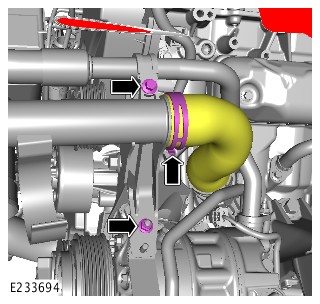
-
- Connect the turbocharger high pressure hose.
- Tighten the hose clamp.
Torque: 5Nm
-
CAUTION:
Install a new bolt.
- Install the steering column lower shaft.
- Install and tighten an new bolt.
Torque: 30Nm
- Install the accessory drive belt.
- Install the front left wheel arch liner.
Refer to:Fender Splash Shield (501-02 Front End Body Panels, Removal and Installation).
- Install the left Exhaust Gas Recirculation (EGR) valve.
Refer to:Left Exhaust Gas Recirculation Valve - TDV6 3.0L Diesel - Gen 2 (303-08A Engine Emission Control - TDV6 3.0L Diesel /TDV6 3.0L Diesel - Gen 1.5/TDV6 3.0L Diesel - Gen 2, Removal and Installation).
- Charge the Air Conditioning (A/C) refrigerant.
Refer to:Air Conditioning System Recovery, Evacuation and Charging (412-00 Climate Control System - General Information, General Procedures).
- Connect the startup battery ground cable.
Refer to:Specifications (414-00 Battery and Charging System - General Information, Specifications).
CLIMATE CONTROL
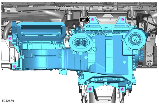
HEATER CORE AND EVAPORATOR HOUSING (G1618358)
- 80.20.01.99
- HEATER UNIT - REMOVE FOR ACCESS AND REFIT
- 3000 CC, TDV6
- 5.70
- USED WITHINS
PART(S)
| STEP | PART NAME | QUANTITY |
|---|---|---|
| Installation Step 1 | Heater housing assembly seal(s) | 3 |
| Installation Step 10 | Steering column intermediate shaft upper bolt | 1 |
| Installation Step 29 | Air conditioning pipe O-ring seal(s) | 4 |
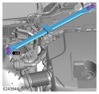
| Installation Step 33 | Engine compartment brace bolts | 4 |
| Installation Step 35 | Engine compartment brace bolts | 4 |
| Installation Step 36 | Steering column lower shaft lower bolt | 1 |
-
This procedure contains some variation in the illustrations depending on the vehicle specification, but the essential information is always correct.
-
This procedure contains illustrations showing certain components removed to provide extra clarity.

- Raise and support the vehicle on a suitable 2 post lift.
Refer to:Lifting (100-02 Jacking and Lifting, Description and Operation).
- Recover the Air Conditioning (A/C) refrigerant.
Refer to:Air Conditioning System Recovery, Evacuation and Charging (412-00 Climate Control System - General Information, General Procedures).
- Remove the windshield wiper linkage assembly.
Refer to:Wiper Linkage Assembly (501-16 Wipers and Washers, Removal and Installation).
- Drain the cooling system.
Refer to:Cooling System Partial Draining and Vacuum Filling (303-03B Engine Cooling - V6 S/C 3.0L Petrol, General Procedures).Refer to:Cooling System Partial Draining and Vacuum Filling (303-03B Engine Cooling - V6 S/C 3.0L Petrol, General Procedures).Refer to:Cooling System Partial Draining and Vacuum Filling (303-03B Engine Cooling - V6 S/C 3.0L Petrol, General Procedures).Refer to:Cooling System Partial Draining and Vacuum Filling (303-03B Engine Cooling - V6 S/C 3.0L Petrol, General Procedures).Refer to:Cooling System Partial Draining and Vacuum Filling (303-03B Engine Cooling - V6 S/C 3.0L Petrol, General Procedures).Refer to:Cooling System Partial Draining and Vacuum Filling (303-03B Engine Cooling - V6 S/C 3.0L Petrol, General Procedures).

- Remove the steering wheel.
Refer to:Steering Wheel (211-04 Steering Column, Removal and Installation).
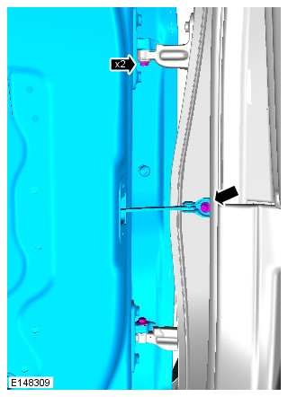
-
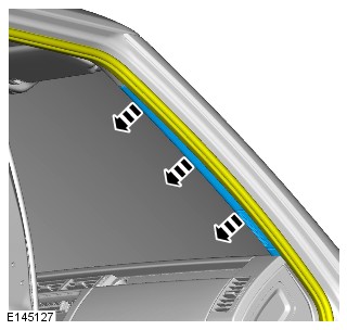
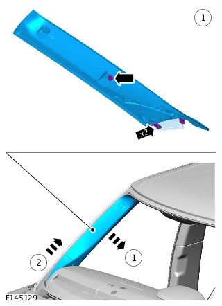
Remove the A-pillar upper trim panel.NOTE:
Repeat this step for the other side.
Refer to:A-Pillar Trim Panel (501-05 Interior Trim and Ornamentation, Removal and Installation).
- Remove the floor console.
Refer to:Floor Console (501-12 Instrument Panel and Console, Removal and Installation).
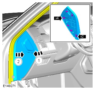
- Remove the upper glovebox.
Refer to:Glove Compartment (501-12 Instrument Panel and Console, Removal and Installation).
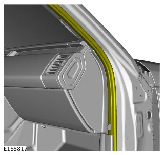
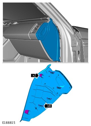
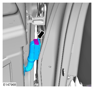
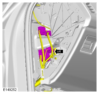
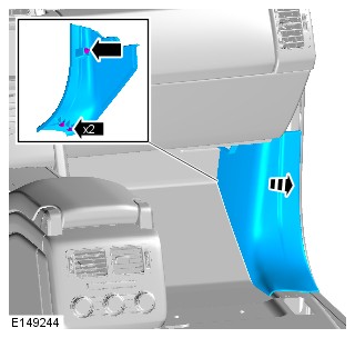
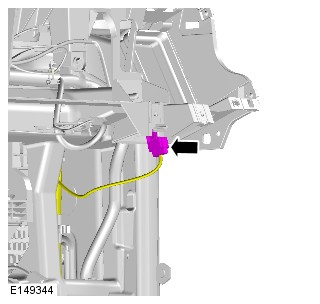
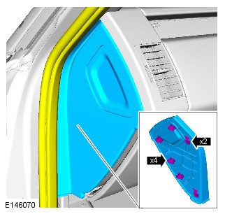
- Remove the cowl side trim panel.
Refer to:Cowl Side Trim Panel (501-05 Interior Trim and Ornamentation, Removal and Installation).


-
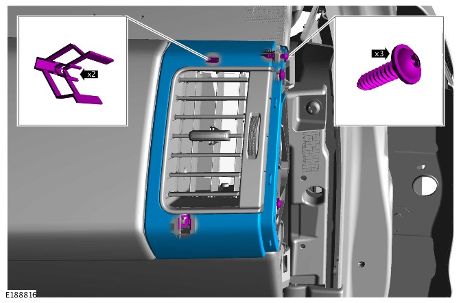
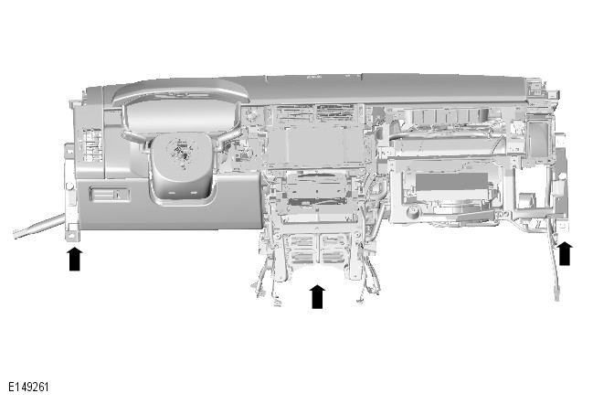
- Install the air vent.
- Install the screw.
- Connect the 4 electrical connectors.
-
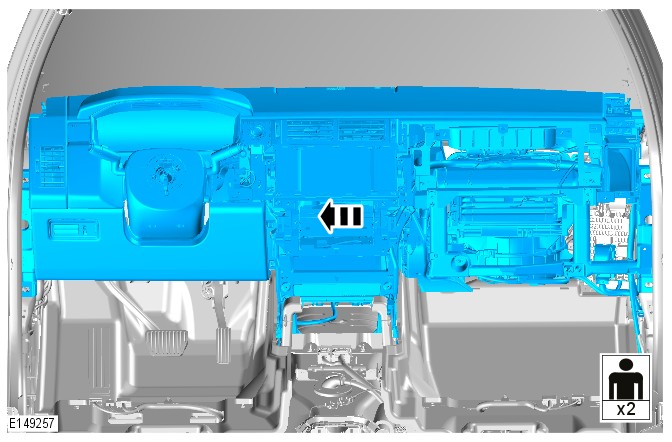
Install the instrument panel assembly.NOTE:
This step requires the aid of another technician.
-
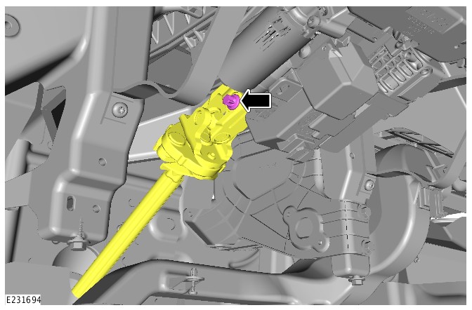
- Install the steering column shaft.
- Install and tighten the bolt.
Torque: 44Nm
-
- Install the bracket.
- Install and tighten the 2 bolts.
Torque: 9Nm
- Install and tighten 2 nuts.
Torque: 9Nm
- Install the windshield defroster trim panel.
-
Install the drain tube.NOTE:
Repeat this step for the other side.
- Connect the 8 electrical connectors.
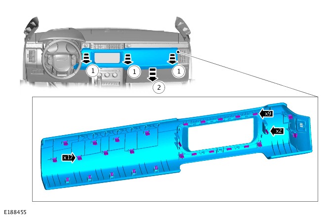
- Install the trim panel.
- Connect the 4 electrical connectors.
- Install the instrument panel side trim.
- Connect the electrical connector.
- Install the cowl side trim panel.
Refer to:Cowl Side Trim Panel (501-05 Interior Trim and Ornamentation, Removal and Installation).
- Install the upper glovebox.
Refer to:Glove Compartment (501-12 Instrument Panel and Console, Removal and Installation).
- Install the floor console.
Refer to:Floor Console (501-12 Instrument Panel and Console, Removal and Installation).
-
Install the A-pillar upper trim panel.NOTE:
Repeat this step for the other side.
Refer to:A-Pillar Trim Panel (501-05 Interior Trim and Ornamentation, Removal and Installation).
- Install the steering wheel.
Refer to:Steering Wheel (211-04 Steering Column, Removal and Installation).
-
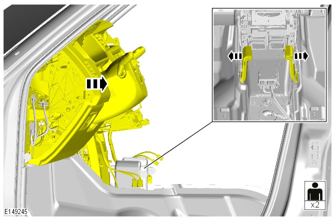
Install the front door assembly.NOTE:
This step requires the aid of another technician.
TorqueTorx bolt: 24NmM8 bolt: 30Nm
- Connect the electrical connector.,
- Connect the 2 coolant hoses.
-
- Install new O-rings.
- Install the A/C pipes.
- Install and tighten the bolt.
Torque: 10Nm
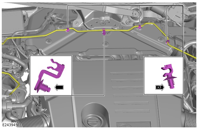
- Install the electrical wiring harness clip.
-
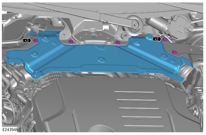
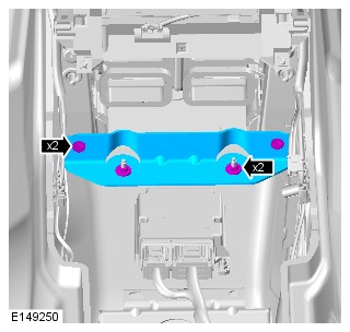
- Install the secondary bulkhead center panel.
- Install and tighten the 5 bolts.
Torque: 6Nm
-
- Install the left engine compartment brace.
- Install and tighten 4 new bolts.
Torque: 55Nm
-
- Install the right engine compartment brace.
- Install and tighten 4 new bolts.
Torque: 55Nm
- Fill the cooling system.
Refer to:Cooling System Partial Draining and Vacuum Filling (303-03B Engine Cooling - V6 S/C 3.0L Petrol, General Procedures).Refer to:Cooling System Partial Draining and Vacuum Filling (303-03B Engine Cooling - V6 S/C 3.0L Petrol, General Procedures).Refer to:Cooling System Partial Draining and Vacuum Filling (303-03B Engine Cooling - V6 S/C 3.0L Petrol, General Procedures).Refer to:Cooling System Partial Draining and Vacuum Filling (303-03B Engine Cooling - V6 S/C 3.0L Petrol, General Procedures).Refer to:Cooling System Partial Draining and Vacuum Filling (303-03B Engine Cooling - V6 S/C 3.0L Petrol, General Procedures).Refer to:Cooling System Partial Draining and Vacuum Filling (303-03B Engine Cooling - V6 S/C 3.0L Petrol, General Procedures).
- Install the windshield wiper linkage assembly.
Refer to:Wiper Linkage Assembly (501-16 Wipers and Washers, Removal and Installation).
- Charge the Air Conditioning (A/C) refrigerant.
Refer to:Air Conditioning System Recovery, Evacuation and Charging (412-00 Climate Control System - General Information, General Procedures).
CLIMATE CONTROL
RECEIVER DRIER (G1618359)
- 82.17.03
- RECEIVER DRIER - RENEW
- ALL DERIVATIVES
- 1.30
- USED WITHINS
Before disconnecting any components, make sure the area is clean and free from foreign material. When disconnected all openings must be sealed.
-
Removal steps in this procedure may contain installation details.
-
Some variation in the illustrations may occur, but the essential information is always correct.
- Raise and support the vehicle.
-
Refer to:Air Conditioning System Recovery, Evacuation and Charging (412-00 Climate Control System - General Information, General Procedures).
-
Refer to:Front Bumper Cover (501-19 Bumpers, Removal and Installation).
- To install, reverse the removal procedure.
CLIMATE CONTROL
AMBIENT AIR QUALITY SENSOR (G1618360)
- 80.10.09
- SENSOR - POLLUTION - DETECTION - RENEW
- ALL DERIVATIVES
- 1.10
- USED WITHINS
Removal steps in this procedure may contain installation details.
- To install, reverse the removal procedure.
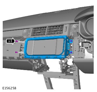
CLIMATE CONTROL
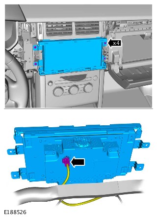
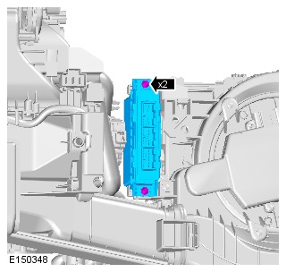
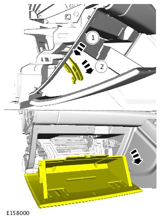
INTEGRATED CONTROL PANEL (G1618361)
- 80.10.02
- CONTROLS - HEATER - RENEW
- ALL DERIVATIVES
- 0.40
- USED WITHINS
-
Removal steps in this procedure may contain installation details.
-
Some components shown removed for clarity.
-
Some variation in the illustrations may occur, but the essential information is always correct.

- To install, reverse the removal procedure.
CLIMATE CONTROL
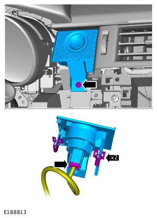
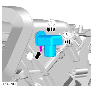
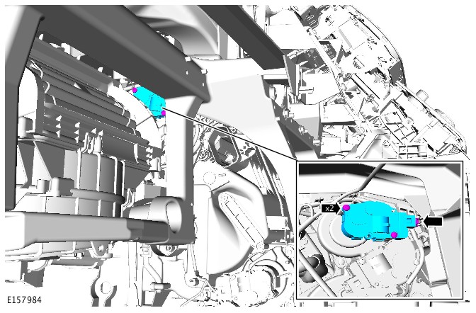
IN-VEHICLE TEMPERATURE SENSOR (G1618362)
- 82.20.93
- AIR TEMPERATURE SENSOR - RENEW
- ALL DERIVATIVES
- 0.20
- USED WITHINS
-
Removal steps in this procedure may contain installation details.
-
Some variation in the illustrations may occur, but the essential information is always correct.
- To install, reverse the removal procedure.
CLIMATE CONTROL
FRONT SUNLOAD SENSOR (G1565879)
- 82.20.92
- SENSOR - SOLAR LIGHT - AUTOMATIC TEMPERATURE CONTROL - RENEW
- ALL DERIVATIVES
- 0.20
- USED WITHINS
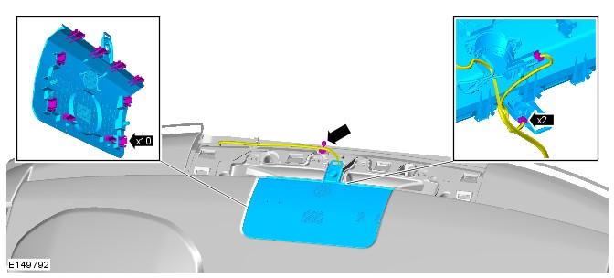
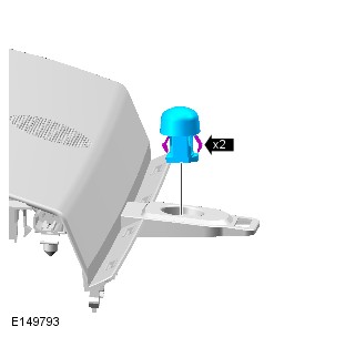
- To install, reverse the removal procedure.
CLIMATE CONTROL
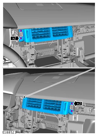
PASSENGER SIDE REGISTER (G1618364)
- 80.15.05
- VENTILATOR - FACE LEVEL - LH - RENEW
- ALL DERIVATIVES
- 0.40
- USED WITHINS
- 80.15.04
- VENTILATOR - FACE LEVEL - RH - RENEW
- ALL DERIVATIVES
- 0.30
- USED WITHINS
-
Removal steps in this procedure may contain installation details.
-
Some illustrations may show left hand drive. Right hand drive is similar, but the essential information shown is always correct.
-
Some variation in the illustrations may occur, but the essential information is always correct.

- To install, reverse the removal procedure.
CLIMATE CONTROL
COOL AIR BYPASS MOTOR (G1618365)
- 82.20.76
- MOTOR - VACUUM - FRESH AIR FLAP - RENEW
- RIGHT HAND DRIVE
- 1.10
- USED WITHINS
-
Some variation in the illustrations may occur, but the essential information is always correct.
-
Removal steps in this procedure may contain installation details.
- Disconnect the battery ground cable.
Refer to:Specifications (414-00 Battery and Charging System - General Information, Specifications).
-
Refer to:Instrument Panel Lower Section (501-12 Instrument Panel and Console, Removal and Installation).
-
Refer to:Glove Compartment (501-12, Removal and Installation).
- To install, reverse the removal procedure.
CLIMATE CONTROL
DRIVER SIDE REGISTER (G1618366)
- 80.15.05
- VENTILATOR - FACE LEVEL - LH - RENEW
- ALL DERIVATIVES
- 0.40
- USED WITHINS
-
Removal steps in this procedure may contain installation details.
-
Some illustrations may show Right hand drive. Left hand drive is similar, but the essential information shown is always correct.
-
Some variation in the illustrations may occur, but the essential information is always correct.


- To install, reverse the removal procedure.
CLIMATE CONTROL
DISTRIBUTION MOTOR – DEMIST (G1618367)
- 80.10.36
- MOTOR - DEMISTER - FRONT WINDSCREEN - RENEW
- RIGHT HAND DRIVE
- 2.00
- USED WITHINS
-
Some variation in the illustrations may occur, but the essential information is always correct.
-
Removal steps in this procedure may contain installation details.
- Disconnect the battery ground cable.
Refer to:Specifications (414-00 Battery and Charging System - General Information, Specifications).
-
Refer to:Glove Compartment (501-12, Removal and Installation).
-
Refer to:Instrument Panel Lower Section (501-12 Instrument Panel and Console, Removal and Installation).
- To install, reverse the removal procedure.
CLIMATE CONTROL
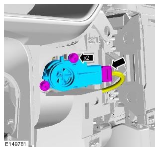
RECIRCULATION MOTOR (G1618368)
- 82.20.77
- MOTOR - VACUUM - RECIRCULATION FLAP - RENEW
- ALL DERIVATIVES
- 0.20
- USED WITHINS
-
Removal steps in this procedure may contain installation details.
-
Some components shown removed for clarity.
-
Some variation in the illustrations may occur, but the essential information is always correct.
-
Right hand drive illustration(s) shown, Left hand drive is similar.

- To install, reverse the removal procedure.
CLIMATE CONTROL
DISTRIBUTION MOTOR - LEFT FRONT FACE/FEET (G1618369)
- 82.20.48
- MOTOR - DISTRIBUTION - FRONT FACE/FEET - LEFT - RENEW
- RIGHT HAND DRIVE
- 2.00
- USED WITHINS
-
Some variation in the illustrations may occur, but the essential information is always correct.
-
Removal steps in this procedure may contain installation details.
- Disconnect the battery ground cable.
Refer to:Specifications (414-00 Battery and Charging System - General Information, Specifications).
-
Refer to:Glove Compartment (501-12, Removal and Installation).
-
Refer to:Instrument Panel Lower Section (501-12 Instrument Panel and Console, Removal and Installation).
- To install, reverse the removal procedure.
CLIMATE CONTROL
DISTRIBUTION MOTOR - RIGHT FRONT FACE/FEET (G1618370)
- 82.20.47
- MOTOR - DISTRIBUTION - FRONT FACE/FEET - RIGHT - RENEW
- RIGHT HAND DRIVE
- 1.10
- USED WITHINS
-
Some variation in the illustrations may occur, but the essential information is always correct.
-
Removal steps in this procedure may contain installation details.
- Disconnect the battery ground cable.
Refer to:Specifications (414-00 Battery and Charging System - General Information, Specifications).
-
Refer to:Instrument Panel Lower Section (501-12 Instrument Panel and Console, Removal and Installation).
-
Refer to:Glove Compartment (501-12, Removal and Installation).
- To install, reverse the removal procedure.
CLIMATE CONTROL
POLLEN FILTER (G1509804)
- 80.15.42
- FILTER - FRESH AIR INTAKE - RENEW
- ALL DERIVATIVES
- 0.10
- USED WITHINS
During this procedure, the ignition must remain in ON, and the A/C system must be in manual mode.
Removal steps in this procedure may contain installation details.
-
WARNING:
Make sure that the blower motor speed is in the minimum position. Failure to follow this instruction may result in personal injury.
CAUTION:It is necessary to set the air conditioning (A/C) system in recirculation mode to allow access to the pollen filter. Do not attempt to manually operate the recirculation door, as this will result to damage of the recirculation motor.
NOTE:Press the recirculation button for three seconds to set the climate control system in to continuous recirculation mode.
During this procedure, the ignition must remain in the ON position, and the A/C system must be in continuous recirculation mode with the fan speed set to minimum.

- To install, reverse the removal procedure.
412-02: Auxiliary Climate Control
AUXILIARY CLIMATE CONTROL (G1618371)
Torque Specifications
| DESCRIPTION | NM | LB-FT | LB-IN |
|---|---|---|---|
| Fuel fired booster heater exhaust bolt | 10 | 7 | - |
| Fuel fired booster heater exhaust nut | 10 | 7 | - |
| Fuel fired booster heater bolts | 10 | 7 | - |
| Fuel fired booster heater fuel pump bolt | 9 | - | 80 |
| Fuel fired booster heater coolant pump bolts | 1.5 | - | 13 |
| Auxiliary refrigerant line bolts | 10 | 7 | - |
| Auxiliary heater core and evaporator core housing sealing plate nuts | 10 | 7 | - |
| Auxiliary heater core and evaporator core housing nuts | 5 | - | 44 |
| Auxiliary thermostatic expansion valve retaining bolts | 4 | - | 35 |
Description and Operation
AUXILIARY CLIMATE CONTROL
ELECTRIC BOOSTER HEATER (G1950053)
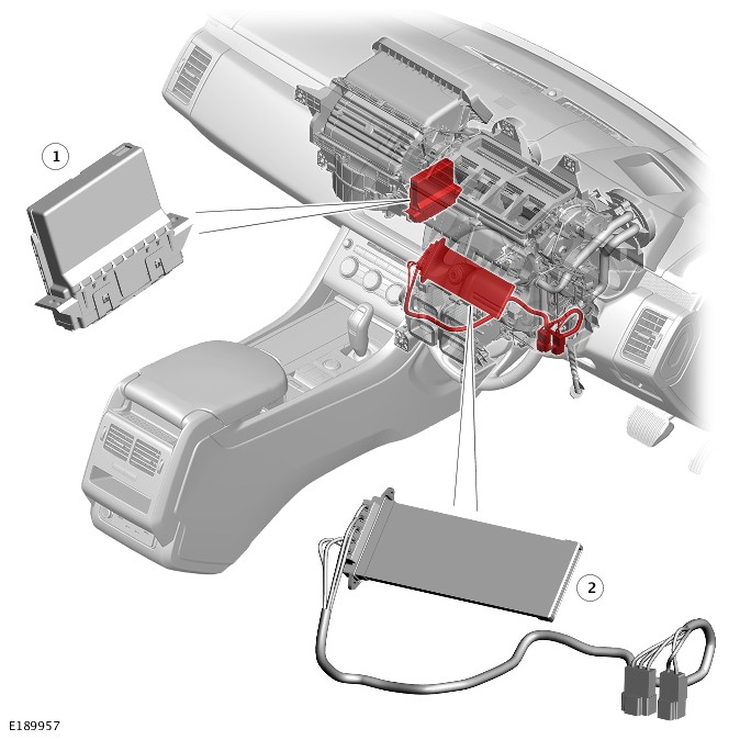
| ITEM | DESCRIPTION |
|---|---|
| 1 | HVAC Control Module |
| 2 | Electric booster heater |
Due to the slower warm up times associated with the engine, an electric booster heater may be fitted to increase heater performance. The electric booster heater does this by heating the air leaving the heater assembly. The electric booster heater comprises ceramic coated thermistor elements. A request for electric booster heater operation originates in the HVAC Control Module. This request is in the form of a relay energize signal to the Rear Junction Box (RJB) and the electric booster heater relays, integral with the RJB. This then provides power to the three sections of the electric booster heater, in accordance to the demand for heating.
The amount of heating requested by the HVAC is based on:
- Ambient air temperature.
- Engine coolant temperature.
- Heating request.
There is also a minimum blower-motor speed required for the electric booster heater operation.
The electric booster heater is limited to 600 Watts. If electrical load management is in force, electric booster heater performance will be reduced.
The electric booster heater is installed in the climate control assembly, on the downstream side of the heater core. It consists of ceramic coated Positive Temperature Coefficient (PTC) thermistor elements, rated at 600 Watts. Electrical power for the booster heater is supplied via two 40A fuses. Operation of the electric booster heater is controlled by the HVAC Control Module.
The electric booster heater consists of a matrix, containing ceramic coated positive temperature coefficient elements, which is installed in the climate control assembly.
Operation of the electric booster heater is activated by the Rear Junction Box (RJB) and the two electric booster heater relays, integral with the RJB. The RJB activates the electric booster heater relays to energize combinations of the three electric booster heater elements as required.
The HVAC Control Module uses the following inputs, to control operation of the electric booster heater:
- Climate control system selections from the Integrated Control Panel (ICP) and the Touch Screen (TS), through the High Speed (HS) Controller Area Network (CAN) comfort systems bus to the Body Control Module/Gateway Module (BCM/GWM) assembly and then the High Speed (HS) Controller Area Network (CAN) Power Mode Zero bus.
- Ambient air temperature and engine coolant temperature from the Powertrain Control Module (PCM) via the FlexRay network to the Body Control Module/Gateway Module (BCM/GWM) assembly and then the High Speed (HS) Controller Area Network (CAN) Power Mode Zero bus.
- Battery state from the BCM/GWM assembly through the High Speed (HS) Controller Area Network (CAN) Power Mode Zero bus.
The HVAC requests operation of the electric booster heater, provided the vehicle is not in transit mode and there are no generator faults recorded, when the following conditions occur:
- The engine is running.
- The blower is on (any speed).
- Heating is requested on the ICP, or on the menu of the TS, and the desired vent temperature (calculated by the HVAC), is not being achieved.
The electrical booster heater elements activated by the HVAC which is proportional to the amount of heating required. If the electrical load management is in force, the electric booster heater performance is reduced.
CONTROL DIAGRAM

A = HARDWIRED; O = LOCAL INTERCONNECT NETWORK (LIN) BUS; ; AV = HIGH SPEED (HS) CONTROLLER AREA NETWORK (CAN) COMFORT SYSTEMS BUS; AX = FLEXRAY; AY = HIGH SPEED (HS) CONTROLLER AREA NETWORK (CAN) POWER MODE ZERO.
| ITEM | DESCRIPTION |
|---|---|
| 1 | HVAC Control Module |
| 2 | Powertrain Control Module (PCM) |
| 3 | Body Control Module/Gateway Module (BCM/GWM) assembly |
| 4 | Touch Screen (TS) |
| 5 | Integrated Control Panel (ICP) |
| 6 | Blower control module |
| 7 | Blower |
| 8 | Electric booster heater |
| 9 | Relay 1 - Electric booster heater |
| 10 | Relay 2- Electric booster heater |
| 11 | Ground |
| 12 | Power supply |
| 13 | In-vehicle temperature sensor |
| 14 | Ambient Air Temperature (AAT) sensor |
| 15 | Engine Coolant Temperature (ECT) sensor |
AUXILIARY CLIMATE CONTROL
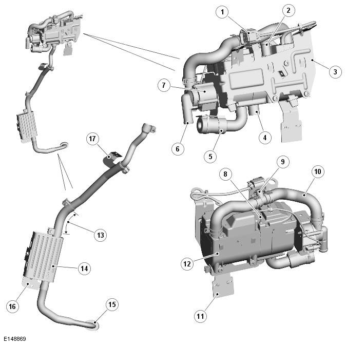
FUEL FIRED BOOSTER HEATER (G1950054)
Diesel Vehicle installation shown; refer to the 'Description' section for petrol vehicle variances.
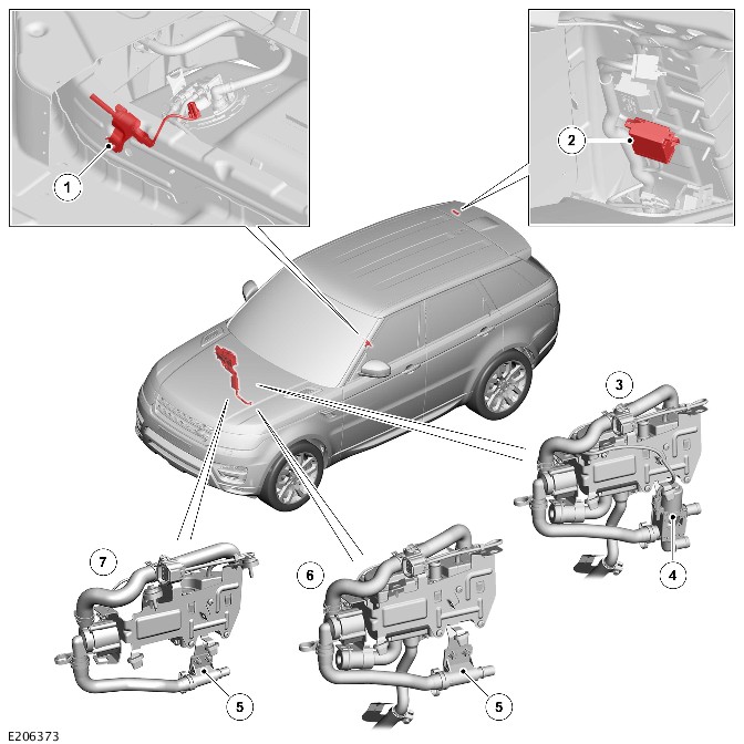
| ITEM | DESCRIPTION |
|---|---|
| 1 | Fuel Fired Booster Heater (FFBH) fuel pump (diesel installation shown, petrol installations similar) |
| 2 | FFBH receiver (vehicles with timed climate control only) |
| 3 | FFBH (vehicles with timed climate control) |
| 4 | FFBH coolant changeover valve (vehicles with timed climate control) |
| 5 | Coolant tube connector (vehicles without timed climate control) |
| 6 | FFBH (vehicles without timed climate control) |
| 7 | FFBH (NAS only) |
Depending on model specification and market, the vehicle may incorporate auxiliary heating in the form of a Fuel Fired Booster Heater (FFBH). The FFBH boosts the temperature of the engine coolant supplied to the climate control assembly and, where fitted, the auxiliary climate control assembly.
Fuel for the FFBH is taken from the vehicle fuel tank, through a fuel line attached to the fuel pump module. A FFBH fuel pump supplies the fuel at low pressure to the FFBH. In the FFBH, the fuel is burned and the resultant heat output is used to heat the engine coolant, which is circulated through the climate control assembly and, where fitted, the auxiliary climate control assembly, by a FFBH coolant pump.
FFBH operation is automatic while the engine is running. Where timed climate control is incorporated, the FFBH can be selected to operate (depending on the ambient air temperature) while the vehicle is parked using the touch screen or a remote control.
Vehicles with timed climate control also incorporate:
- A FFBH receiver for communication with the remote control
- A FFBH coolant changeover valve that allows the climate control coolant circuit to be isolated from the engine coolant circuit to reduce the warmup time of the passenger compartment.
NAS vehicles are not fitted with an operational Fuel Fired Booster Heater (FFBH).
FUEL FIRED BOOSTER HEATER
| ITEM | DESCRIPTION |
|---|---|
| 1 | Electrical connector |
| 2 | Coolant outlet |
| 3 | Support bracket |
| 4 | Exhaust outlet |
| 5 | Air intake hose (a canister type acoustic muffler is incorporated into the air intake hose) |
| 6 | Coolant pump inlet |
| 7 | Coolant pump |
| 8 | Fuel inlet |
| 9 | Bleed screw |
| 10 | Coolant inlet hose |
| 11 | Coolant tube connector/FFBH coolant changeover valve bracket |
| 12 | Fuel fired booster heater base unit |
| 13 | Exhaust flexible section |
| 14 | Muffler |
| 15 | Exhaust tailpipe bush |
| 16 | Muffler bracket |
| 17 | Exhaust bracket |
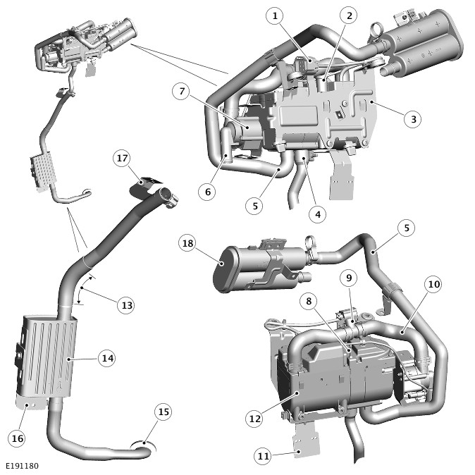
| ITEM | DESCRIPTION |
|---|---|
| 1 | Electrical connector |
| 2 | Coolant outlet |
| 3 | Support bracket |
| 4 | Exhaust outlet |
| 5 | Air intake hose |
| 6 | Coolant pump inlet |
| 7 | Coolant pump |
| 8 | Fuel inlet |
| 9 | Bleed screw |
| 10 | Coolant inlet hose |
| 11 | Coolant tube connector/FFBH coolant changeover valve bracket |
| 12 | Fuel fired booster heater base unit |
| 13 | Exhaust flexible section |
| 14 | Muffler |
| 15 | Exhaust tailpipe bush |
| 16 | Muffler bracket |
| 17 | Exhaust bracket |
| 18 | Charcoal canister (where fitted) |
The Fuel Fired Booster Heater (FFBH) is installed in the engine compartment, on a support bracket attached to the rear of the right suspension housing. It is connected in series with the coolant supply to the climate control assembly. A flying lead on the FFBH connects it to the vehicle wiring. The FFBH consists of the following:
- A Fuel Fired Booster Heater Control Module (FFBHCM)
- A combustion air fan
- A combustion chamber
- A heat exchanger
- A coolant pump
- An air intake hose and muffler
- An exhaust pipe and muffler.
The Fuel Fired Booster Heater Control Module (FFBHCM) controls and monitors operation of the Fuel Fired Booster Heater (FFBH) system. Power for the FFBHCM is provided by a permanent feed from the QCCM (Quiescent Current Control Module) integrated in the RJB (Rear Junction Box). A Local Interconnect Network (LIN) bus connection provides the communication link between the FFBHCM and the HVAC (HVAC Control Module). The FFBHCM also has:
- A ground connection
- Power feed and ground connections with the FFBH coolant pump
- A power feed connection with the FFBH fuel pump
- A signal line connection with the FFBH receiver (vehicles with timed climate control only).
The combustion air fan regulates the flow of air to the heater so as to ensure correct combustion. If the heater is operational while the engine is stopped or the heater enters the control idle phase, the air fan will continue to run in order to cool the combustion chamber in readiness for the next required start. The operation of the fan may be noticed during this process. This is perfectly normal.
The combustion chamber is located in the heat exchanger casing and the combustion air fan casing. The fuel feed pipe of the combustion chamber extends up through the cover of the combustion air fan. A glow plug is installed in the combustion chamber to provide the ignition source for the fuel:air mixture.
The heat exchanger transfers heat generated by the combustion chamber to the engine coolant. An overheating temperature sensor and a surface temperature sensor are installed in the heat exchanger and connected to the Fuel Fired Booster Heater Control Module (FFBHCM). The FFBHCM uses the temperature inputs to control system operation.
The Fuel Fired Booster Heater (FFBH) coolant pump is an electric pump attached to outboard end of the FFBH support bracket. The pump intake is connected to either the heater coolant feed from the engine (vehicles without timed climate control) or to the FFBH coolant changeover valve (vehicles with timed climate control). A hose, which incorporates a bleed screw, connects the outlet of the coolant pump to the coolant inlet of the FFBH.
The coolant pump runs continuously while the FFBH is in control idle or active operating modes. While the FFBH is inactive, coolant flow is reliant on the engine coolant pump.
A canister type muffler and filter is incorporated into the air intake hose.
Depending on specification some petrol vehicles are fitted with an extended air-intake hose and activated charcoal canister.
The exhaust pipe and muffler directs exhaust combustion gases to atmosphere below the vehicle, to the rear of the right front wheel arch and towards the center of the vehicle. Exhaust vapor may be visible when the Fuel Fired Booster Heater (FFBH) is running, depending on atmospheric conditions. Under normal operating conditions, the exhaust vapor will subside once the FFBH has achieved “Power status” and the exhaust pipe has reached normal operating temperature.
Under certain circumstances, for example after heater replacement or the disconnection of the fuel or coolant circuits, smoke may be visible from the general vicinity of the heater rather than the outlet of the exhaust. This may be as a result of residual fuel or coolant on the exhaust or heater body as a result of the service procedure. Under these circumstances, the heater must be run continually for 15-20 minutes until there are no signs of excessive smoke.
FUEL FIRED BOOSTER HEATER (NAS ONLY)
NAS vehicles are not fitted with an operational Fuel Fired Booster Heater (FFBH).
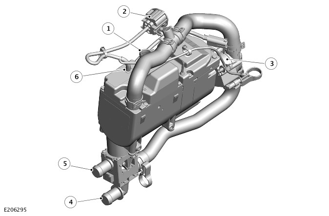
| ITEM | DESCRIPTION |
|---|---|
| 1 | Connection to heater |
| 2 | Electrical connector |
| 3 | Fuel Fired Booster Heater (FFBH) coolant pump |
| 4 | Blank off connection |
| 5 | Connection to engine cooling system |
| 6 | Fuel Fired Booster Heater Control Module (FFBHCM) |
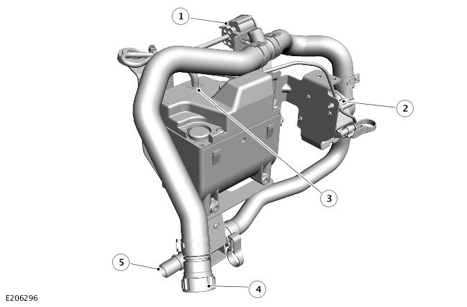
| ITEM | DESCRIPTION |
|---|---|
| 1 | Electrical connector |
| 2 | Fuel Fired Booster Heater (FFBH) coolant pump |
| 3 | Fuel Fired Booster Heater Control Module (FFBHCM) |
| 4 | Connection to heater |
| 5 | Connection to engine cooling system |
The Fuel Fired Booster Heater (FFBH) only uses the FFBH coolant pump. The FFBH coolant pump is used to pump the coolant through the heater system. The FFBH coolant pump is controlled by the HVAC Control Module through the Fuel Fired Booster Heater Control Module (FFBHCM).
The Fuel Fired Booster Heater Control Module (FFBHCM) controls and monitors operation of the Fuel Fired Booster Heater (FFBH) coolant pump. Power for the FFBHCM is provided by a permanent feed from the QCCM (Quiescent Current Control Module) integrated in the RJB (Rear Junction Box). A Local Interconnect Network (LIN) bus connection provides the communication link between the FFBHCM and the HVAC (HVAC Control Module). The FFBHCM also has:
- A ground connection
- Power feed and ground connections with the FFBH coolant pump.
FUEL FIRED BOOSTER HEATER FUEL PUMP
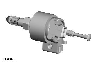
The Fuel Fired Booster Heater (FFBH) fuel pump is installed in a rubber mounting attached to a crossmember under the rear floor, above the fuel tank. The pump is a self priming, solenoid operated plunger pump. The Fuel Fired Booster Heater Control Module (FFBHCM) in the FFBH outputs a PWM (Pulse Width Modulation) signal to control the operation of the pump. When the pump is de-energized, it provides a positive shut-off of the fuel supply to the FFBH.
CHARCOAL CANISTER (PETROL VEHICLES ONLY)

Depending on vehicle specification, an extended air-intake hose and activated charcoal canister may be fitted to the Fuel Fired Booster Heater (FFBH).
The canister functions as both an acoustic silencer and, under certain operational and environmental conditions, captures and recycles the evaporative emissions exhausted by the FFBH.
The canister is a serviceable item and can be replaced if blocked or damaged. A Diagnostic Trouble Code (DTC) will be stored in the Body Control Module/Gateway Module (BCM/GWM) if a restriction is present. This can then be verified by removing the canister and performing an FFBH activation test.
FUEL FIRED BOOSTER HEATER COOLANT CHANGEOVER VALVE (VEHICLES WITH TIMED CLIMATE CONTROL ONLY)
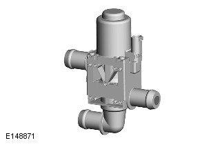
Where fitted, the Fuel Fired Booster Heater (FFBH) coolant changeover valve is attached to a bracket on the underside of the FFBH. The FFBH coolant changeover valve is a normally open solenoid valve installed between the supply and return sides of the heater coolant circuit. When de-energized, the FFBH coolant changeover valve connects the heater coolant circuit to the engine coolant circuit. When energized, the FFBH coolant changeover valve isolates the heater coolant circuit from the engine coolant circuit.
Operation of the FFBH coolant changeover valve is controlled by a power feed from the HVAC (HVAC Control Module).
FUEL FIRED BOOSTER HEATER RECEIVER (VEHICLES WITH TIMED CLIMATE CONTROL ONLY)
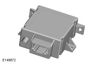
The Fuel Fired Booster Heater (FFBH) receiver translates the FFBH remote control radio signals, relayed from the TV antenna amplifier, into a voltage output to the FFBH. When a request for timed climate control is received, the FFBH receiver outputs a battery power feed to the FFBH unit. When a request to switch off timed climate control is received, the FFBH receiver disconnects the power feed.
The FFBH receiver has a permanent power feed from the Body Control Module/Gateway Module Assembly (BCM/GWM) and is connected to the television antenna amplifier by a coaxial cable. For additional information, refer to:Antenna (415-01 Information and Entertainment System - Vehicles With: InControl Touch Pro, Description and Operation).
FUEL FIRED BOOSTER HEATER REMOTE CONTROL (VEHICLES WITH TIMED CLIMATE CONTROL ONLY)
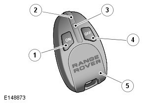
| ITEM | DESCRIPTION |
|---|---|
| 1 | ON switch |
| 2 | Antenna |
| 3 | Light Emitting Diode (LED) operating indicator |
| 4 | OFF switch |
| 5 | Battery cover |
Avoid touching the antenna when operating the ON or OFF switch. Covering the antenna will have an adverse affect on the transmitting range.
The Fuel Fired Booster Heater (FFBH) remote control enables the timed climate control program to be activated and deactivated from outside the vehicle. The remote control has an approximate range of 100 m (328 ft). There is no need to point the remote control at the vehicle. Press and hold the ON button for approximately 2 seconds. The Light Emitting Diode (LED) illuminates green to confirm that a timed climate program has been initiated. The LED continues to flash for a few seconds to indicate that the timed climate is active.
The timed climate program continues for 20-30 minutes, after which it switches off automatically to prevent the vehicle's battery from discharging. It also turns off automatically if the engine is started.
The LED indicator signals various states and conditions for the timed climate as follows:
- Illuminates green when the ON button is pressed and then quickly flashes green, to indicate that heater operation has been requested.
- Illuminates green followed by red when the OFF button is pressed, to indicate that the heater has been requested to shut down.
- Illuminates green and then quickly flashes red when either the ON or OFF button is pressed, to indicate that there is no communication with the receiver. This normally occurs if the vehicle is too far away.
- Illuminates green and then slowly flashes red when either the ON or OFF button is pressed, to indicate that there is an error.
- Flashes red when either the ON or OFF button is pressed, to indicate that the timed climate remote battery needs replacing.
The timed climate control program will only operate once per engine start to maintain battery condition.
With the front of the Fuel Fired Booster Heater (FFBH) remote control facing upwards. Press down on the rear of the battery cover and push completely off to reveal the battery compartment. Remove the old battery. Install a new, unused 3 volt CR2032 battery and make sure that the correct polarity is maintained. Align and push the cover back to the original position.
The battery should be inserted with the positive side facing upwards.
Each Fuel Fired Booster Heater (FFBH) remote control must be 'paired' to the FFBH receiver to enable communications. Each remote control has a unique identification number which is stored by the receiver. The receiver can store up 4 remote control identification numbers. If a fifth remote control is paired to the receiver, the receiver will overwrite the first paired remote control number.
Pair a remote control to the vehicle, as follows:
- Remove fuse F1 (5A) or F27 (5A) (depending on market specification) from the Body Control Module/Gateway Module Assembly (BCM/GWM).
- Wait for a minimum of 5 seconds.
- Replace fuse F1 (5A) or F27 (5A) (depending on market specification) in the BCM/GWM then, within 5 seconds, press and hold the remote control OFF switch.
- A successful pairing is indicated by the remote control Light Emitting Diode (LED) illuminating red for 2 seconds.
The pairing process relies on the Fuel Fired Booster Heater (FFBH) receiver having the power supply removed and then the power supply re-instated. The fuse method is the easiest method but it can also be achieved by battery disconnection or removal of the harness connector from the FFBH receiver.
FUEL FIRED BOOSTER HEATER (NON NAS)
The NAS petrol engine vehicles are not fitted with an operational Fuel Fired Booster Heater (FFBH).
Operation of the Fuel Fired Booster Heater (FFBH) is controlled by a status message from the HVAC (HVAC Control Module) to the Fuel Fired Booster Heater Control Module (FFBHCM). A similar status message, from the Fuel Fired Booster Heater Control Module (FFBHCM) to the HVAC, advises the HVAC of the current operating status of the FFBH.
While the engine is running, if the ambient air temperature is less than 7°C (45°F) (Diesel) or 1°C (34°F) (Petrol) and the engine coolant temperature is less than 75°C (167°F) the HVAC changes the status message from 'heater off' to 'supplemental heat'. The FFBHCM then changes the status message it sends the HVAC to 'supplemental heat' and starts the FFBH.
If the engine is started and the FFBH is requested. The HVAC closes the recirculation flap for the first 4 minutes or until the vehicle road speed exceeds 16 km/h (10 mph). The HVAC opens the recirculation flap to enable the ingress of fresh air. This feature is over ridden if the MAX demist switch on the Integrated Control Panel (ICP) is selected or if the HVAC detects a risk of misting of the windshield.
The FFBH will not start, or will discontinue operation, if any of the following occur:
- The FFBHCM is in the error lockout mode (see DIAGNOSTICS below).
- The engine stops running for approximately 4 seconds. The time delay is included for stall detection.
- The HVAC receives a 'fuel cut-off' message from the Body Control Moduel/Gateway Module (BCM/GWM) on the High Speed (HS) Controller Area Network (CAN) comfort systems bus. The BCM/GWM sends the message if it receives a crash signal from the RCM (Restraint Control Module). For additional information, refer to:Airbag and Safety Belt Pretensioner Supplemental Restraint System (501-20B Supplementary Restraint System, Description and Operation).
- The HVAC receives a low fuel level message from the BCM/GWM on the HS CAN comfort systems bus.
- The Quiescent Current Control Module (QCCM) integrated into the Rear Junction Box (RJB) disconnects the power supply to the FFBH. For additional information, refer to:Battery and Cables (414-01 Battery, Mounting and Cables, Description and Operation).
If the FFBHCM does not start the FFBH, or discontinues operation, the status message to the HVAC remains at, or changes to, 'heater off'.
If the ambient air temperature increases to 10°C (50°F) (Diesel) or 4°C (40°F) (Petrol) or the engine coolant temperature increases to 88°C (190°F) The HVAC cancels supplemental heating, by changing the status message to the FFBHCM back to 'heater off'. The FFBHCM then cancels FFBH operation and changes the status message to the HVAC to 'heater off'.
At the beginning of a start sequence, the Fuel Fired Booster Heater Control Module (FFBHCM) energizes the Fuel Fired Booster Heater (FFBH) coolant pump then operates the following in a preset sequence to start the FFBH:
- The combustion air fan
- The glow plug
- The FFBH fuel pump.
Once combustion has stabilized, the FFBHCM switches off the glow plug. If the FFBH fails to ignite the FFBHCM repeats the start sequence.
While the Fuel Fired Booster Heater (FFBH) is running, the Fuel Fired Booster Heater Control Module (FFBHCM) depending on the temperature of the coolant in the heat exchanger cycles between:
- Power load combustion
- High load combustion
- Low load combustion
- A control idle phase of operation.
The heat output level at low load combustion is 2.3 kW. This rises to 5 kW at high load combustion and 5.2 kW at power load combustion. The FFBHCM transmits the amount of fuel used by the FFBH to the Body Control Moduel/Gateway Module (BCM/GWM), and the FFBH coolant temperature to the HVAC (HVAC Control Module).
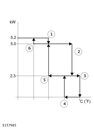
| SWITCHING POINT | TEMPERATURE, ºC (ºF) | |
|---|---|---|
| ITEM NUMBER | DESCRIPTION | |
| 1 | Power load to high load | 65ºC (149ºF) |
| 2 | High load to low load | 80ºC (176ºF) |
| 3 | Low load to control idle | 85ºC (185ºF) |
| 4 | Control idle to low load | 75ºC (167ºF) |
| 5 | Low load to high load | 65ºC (149ºF) |
| 6 | High load to power load | 55ºC (131ºF) |
The switching point temperatures are for reference only and may vary depending on the fuel type and engine size.
After the start sequence, the Fuel Fired Booster Heater Control Module (FFBHCM) maintains power load combustion until the coolant temperature reaches switching point temperature 1. At this temperature, the FFBHCM decreases the speed of the FFBH fuel pump and the combustion air fan to enable high load combustion. The FFBHCM maintains high load combustion while the coolant temperature remains between switching point temperatures 2 and 6.
At high load combustion the temperature of the coolant will increase or decrease depending on the amount of heat required to heat the vehicle interior. If the coolant temperature decreases to switching point temperature 6, the FFBHCM increases the speed of the FFBH fuel pump and the combustion air fan to full speed, to return to power load combustion. If the coolant temperature increases to switching point temperature 2. The FFBHCM decreases the speed of the FFBH fuel pump and the combustion air fan to enable low load combustion.
At low load combustion the temperature of the coolant will again increase or decrease depending on the amount of heat required to heat the vehicle interior. If the coolant temperature decreases to switching point temperature 5. The FFBHCM increases the speed of the FFBH fuel pump and the combustion air fan to enable high load combustion. If the coolant temperature increases to switching point temperature 3, the FFBHCM enters a control idle phase of operation.
On entering the control idle phase, the FFBHCM immediately switches the FFBH fuel pump off, to stop combustion, and starts a timer for the combustion air fan. After a 90 seconds (diesel vehicles) or 120 seconds (petrol vehicles) cool down period. The FFBHCM switches the combustion air fan off and then remains in the control idle phase while the coolant temperature remains above switching point temperature 4. If the coolant temperature decreases to switching point temperature 4, the FFBHCM initiates a start to low load combustion.
To stop the Fuel Fired Booster Heater (FFBH), the Fuel Fired Booster Heater Control Module (FFBHCM) de-energizes the FFBH fuel pump to stop combustion. The combustion air fan and the coolant pump continues operation for a time, to cool down the FFBH. The cool down time is approximately 90 (diesel vehicles) or 120 (petrol vehicles) seconds.
The Fuel Fired Booster Heater Control Module (FFBHCM) monitors the Fuel Fired Booster Heater (FFBH) system for faults. Any faults detected are stored in a volatile memory in the FFBHCM, which can be interrogated by Land Rover approved diagnostic equipment via the Medium Speed (MS) Controller Area Network (CAN) comfort systems bus. A maximum of three faults and associated freeze frame data can be stored at any one time. If a further fault is detected, the oldest fault is overwritten by the new fault.
The FFBHCM also incorporates an error lockout mode of operation that inhibits operation to prevent serious faults from causing further damage to the system. In the error lockout mode, the FFBHCM immediately stops the FFBH fuel pump, and stops the combustion air fan and coolant pump after the cool down time. Error lockout occurs for start sequence failures, combustion flameouts, heat exchanger casing overheat and if the primary battery voltage is out of limits.
- Start failure and flameout: If a start sequence fails to establish combustion, or a flameout occurs after combustion is established, the FFBHCM immediately initiates another start sequence. The start failure or flameout is also recorded by an event timer in the FFBHCM. The event timer is increased by one after each start failure or flameout, and decreased by one if a subsequent start is successful. If the event timer increases to three (over any number of drive cycles), the FFBHCM enters the error lockout mode.
- Heat exchanger casing overheat: To protect the system from excessive temperatures, the FFBHCM enters the error lockout mode if the heat exchanger coolant temperature exceeds 125°C (257°F).
- Battery voltage out of limits: Error lockout will occur if the primary battery voltage is outside the limits of 10.5V to 16.0V.
The error lockout mode can be cleared using Land Rover approved diagnostic equipment, or by disconnecting the battery power supply to the FFBH for a minimum of 10 seconds.
TIMED CLIMATE CONTROL
Where fitted, timed climate control provides a comfortable temperature in the passenger compartment of a vehicle parked with the engine off. When timed climate control operates, the passenger compartment is either heated by the Fuel Fired Booster Heater (FFBH) and climate control blower (parked heating) or cooled by the climate control blower (parked ventilation), depending on the ambient air temperature. Parked heating occurs if the ambient air temperature is less than 16°C (61°F). Parked ventilation occurs if the ambient air temperature is 16°C (61°F) or more. To prevent excessive drain on the battery, both parked heating and parked ventilation are automatically de-activated after 30 minutes.
In very cold conditions timed climate control also warms the engine to aid starting. Engine warming occurs if the ambient air temperature is -25°C ( -13°F) or below.
When timed climate control is operating, the Light Emitting Diode (LED) in the AUTO or A/C switch on the Integrated Control Panel (ICP) will flash. If the AUTO switch LED flashes the engine or passenger compartment are being heated. If the A/C switch LED flashes the passenger compartment is being ventilated.
Timed climate control is controlled using either the touch screen or the FFBH remote control.
In order to minimize the potential for odor ingress from the FFBH, the HVAC (HVAC Control Module) will automatically close the recirculation door in the climate control assembly for the first few minutes of FFBH operation when activated by the timed climate control feature.
The touch screen is used for direct selection of timed climate control or to program one or two 'on/off' cycle start-times per day, and one 'on/off' cycle start-time further in the future. The programmed start times are stored in the Body Control Moduel/Gateway Module (BCM/GWM). The direct selection and programmed time modes of operation are selected when the engine is stopped and the smart key is in the vehicle. The key can then be removed and the vehicle locked. Any timed event will automatically run without the key inside the vehicle.
At a programmed start time or a direct selection on the touch screen, the BCM/GWM sends a start signal to the HVAC Control Module via the High Speed (HS) Controller Area Network (CAN) comfort systems bus. The HVAC Control Module then initiates the appropriate mode of timed climate control operation.
To set a timed climate program:
- Press the HOME MENU switch.
- Touch the Timed climate soft key. This soft key may be set on a personal shortcut or accessed via the Extra Features soft key. Select 7 day timer, or single event, then select the timer soft key. If the 7 day timer is selected, then select the day for which you want to set a program. Alternatively, select All week to select the same start time for every day.
- Touch the Timer 1 or Timer 2 soft key. The timers can be toggled between on and off using the power soft key.
- Touch the up or down arrows to set the start time. Hours and minutes are adjusted separately.
- Touch OK. The screen will display the activation time. If required, set the time for the other timer using the same process.
- Once set, the timer events can be turned on or off as required in the Timed climate screen by selecting the 7 day timer or the single event soft key.
-
Set times to be programmed according to the instructions on the touch screen.
-
Timed climate control will only operate once between engine starts. For example, a timed climate control request from the Fuel Fired Booster Heater (FFBH) remote control will not be performed if a programmed timed climate control event has already occurred.
Any programmed timed climate control cycle may be cancelled by touching the relevant power soft key on the timer set up menu or the Power soft key on the Timed climate information home menu.
When timed climate control is selected on or off with the Fuel Fired Booster Heater (FFBH) remote control. The request is received by the FFBH receiver via the right TV antenna and the TV antenna amplifier. The FFBH receiver relays the request as a hardwired signal to the Fuel Fired Booster Heater Control Module (FFBHCM). On receipt of the request, the FFBHCM sends the request to the HVAC Control Module on the Local Interconnect Network (LIN) bus. The HVAC then initiates the appropriate mode of timed climate control operation.
A 'handshake' signal is sent back from the FFBH receiver to the FFBH remote control to confirm a valid on or off request and activate the remote control Light Emitting Diode (LED) accordingly.
The ‘handshake’ signal only confirms the Fuel Fired Booster Heater (FFBH) remote control to the FFBH receiver communications was successful. Not that the request has been performed.
When the HVAC (HVAC Control Module) receives a timed climate control start request, its response depends on the ambient air temperature:
- If the ambient temperature is 15°C (59°F) or more, the HVAC initiates parked ventilation and:
- Operates the blower, depending on the ambient temperature, between 35% and 50% of the maximum speed.
- Operates the distribution doors in the heater assembly to direct the air to the face vents.
- If the ambient temperature is less than 16°C (61°F) and more than -25°C (-13°F), the HVAC initiates parked heating and:
- Energizes the FFBH coolant changeover valve.
- Sends a Local Interconnect Network (LIN) bus message to activate the Fuel Fired Booster Heater (FFBH).
- Operates the blower, depending on the ambient temperature, between 35% and 50% of the maximum speed.
- Operates the distribution doors in the heater assembly to direct the air to the footwell vents for approximately 30 seconds. Then to either only the windscreen, or to both the footwell vents and the windscreen, depending on the ambient air temperature.
- If the ambient temperature is -25°C (-13°F) or below. The HVAC sends a LIN bus message to activate the FFBH, but leaves the FFBH coolant changeover valve de-energized and does not operate the blower or distribution doors. Heated coolant is circulated around the engine and heater core(s) to heat the engine and improve engine starting. Once the FFBH coolant temperature is above a suitable threshold the blower is switched on and passenger compartment heating commenced.
The FFBH will only activate in timed climate control if the following threshold conditions are met:
- Pre-burn primary battery voltage check: ≥11.5V (at the FFBH terminals).
- Pre-burn Engine Coolant Temperature (ECT) check: ≤15°C (internal FFBH measurement).
- Pre-burn fuel level check: ≥7.5 liters (value stored in the FFBH at ignition off).
The fuel level value stored within the FFBH is only updated when the engine is running. When starting the FFBH in timed climate control with the engine off, the fuel level value used in the FFBH calculations will be that stored at the ignition off event. It is therefore possible for the FFBH to fail to operate in timed climate control if the engine was stopped with a low fuel level. If the fuel tank is subsequently refueled, the FFBH stored fuel level will still read low if the engine has not been started since refueling.
After 30 minutes, or if timed climate control is selected off with the touch screen or remote control, the HVAC discontinues timed climate control operation:
- If parked ventilation is active, the HVAC:
- Switches off the blower.
- Returns the distribution doors to the previous settings.
- If parked heating is active, the HVAC:
- Sends a LIN bus message to de-activate the FFBH.
- Switches off the blower.
- Returns the distribution doors to the previous settings.
- After 3 minutes, de-energizes the FFBH coolant changeover valve.
Parked ventilation is automatically de-activated when the ignition is switched on.
Parked heating:
- Is de-activated when the engine starts if the Engine Coolant Temperature (ECT) is equal to or more than the heater coolant temperature.
- If the ECT is less than the heater coolant temperature, parked heating remains active until the ECT reaches the heater coolant temperature. The FFBH coolant changeover valve also remains closed until the ECT reaches the heater coolant temperature.
FUEL FIRED BOOSTER HEATER (NAS ONLY)
The Fuel Fired Booster Heater (FFBH) has only the FFBH coolant pump operational. The operation is control from the HVAC Control Module through the Fuel Fired Booster Heater Control Module (FFBHCM).
The FFBH coolant pump is operated to control the flow of engine coolant through the heater core in the climate control assembly.
CONTROL DIAGRAM - 1 OF 2 - FUEL FIRED BOOSTER HEATER
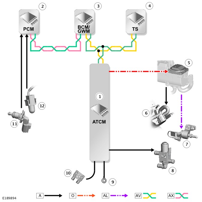
A = HARDWIRED: O = LOCAL INTERCONNECT NETWORK (LIN) BUS: AL = PULSE WIDTH MODULATION (PWM): AV = HIGH SPEED (HS) CONTROLLER AREA NETWORK (CAN) COMFORT SYSTEMS BUS: AX = FLEXRAY.
| ITEM | DESCRIPTION |
|---|---|
| 1 | HVAC Control Module |
| 2 | Powertrain Control Module (PCM) |
| 3 | Body Control Module/Gateway Module (BCM/GWM) assembly |
| 4 | Touch Screen (TS) |
| 5 | Fuel Fired Booster Heater Control Module (FFBHCM) |
| 6 | Fuel Fired Booster Heater (FFBH) coolant pump |
| 7 | FFBH fuel pump |
| 8 | FFBH coolant changeover valve (on vehicles with timed climate control only) |
| 9 | Ground |
| 10 | Power supply |
| 11 | Engine Coolant Temperature (ECT) sensor |
| 12 | Ambient Air Temperature (AAT) sensor |
CONTROL DIAGRAM - 2 OF 2 - REMOTE CONTROL
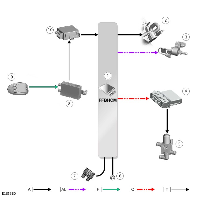
A = HARDWIRED: AL = PULSE WIDTH MODULATION (PWM): F = RADIO FREQUENCY (RF) TRANSMISSION: O = LOCAL INTERCONNECT NETWORK (LIN) BUS: T = CO-AXIAL.
| ITEM | DESCRIPTION |
|---|---|
| 1 | Fuel Fired Booster Heater Control Module (FFBHCM) |
| 2 | Fuel Fired Booster Heater (FFBH) coolant pump |
| 3 | FFBH fuel pump |
| 4 | HVAC Control Module |
| 5 | FFBH coolant changeover valve |
| 6 | Ground |
| 7 | Power supply |
| 8 | FFBH antenna amplifier |
| 9 | FFBH remote control |
| 10 | FFBH receiver |
AUXILIARY CLIMATE CONTROL (G1950055)
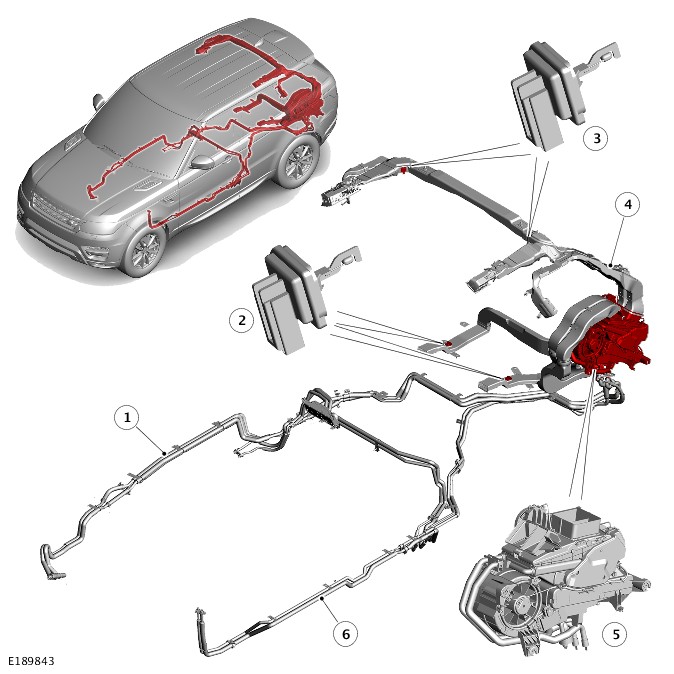
| ITEM | DESCRIPTION |
|---|---|
| 1 | Coolant pipes |
| 2 | Duct air temperature sensor - foot ducts (2 off) |
| 3 | Duct air temperature sensor - face ducts (2 off) |
| 4 | Air distribution system |
| 5 | Auxiliary climate control assembly |
| 6 | Air conditioning pipes |
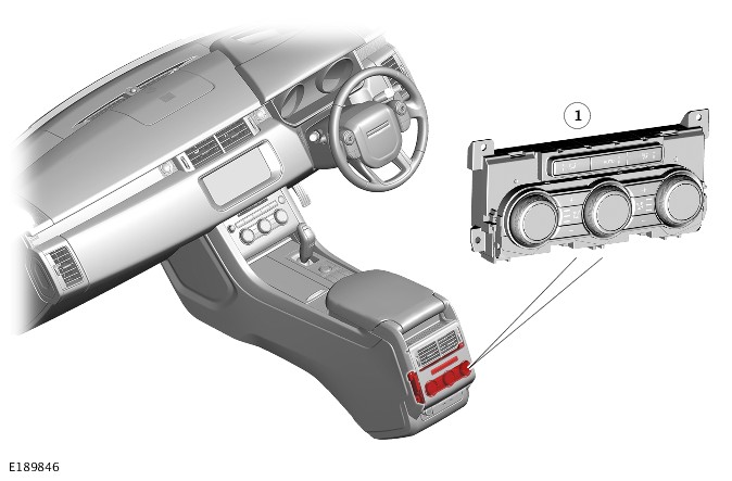
| ITEM | DESCRIPTION |
|---|---|
| 1 | Rear Integrated Control Panel (RICP) |
The auxiliary climate control system provides additional air distribution vents and separate temperature zones for the left and right areas of the rear seats. The auxiliary climate control system consists of:
- An auxiliary climate control assembly.
- A refrigerant circuit.
- A heating circuit.
- A distribution system.
- The RICP (Rear Integrated Control Panel).
Operation of the auxiliary climate control system is controlled by the HVAC Control Module, the Rear Integrated Control Panel (RICP) and the Touch Screen (TS).For additional information, refer to:Control Components (412-01 Climate Control, Description and Operation).
Air from the passenger compartment is recirculated through the auxiliary climate control assembly, where the air is temperature regulated and then directed through the distribution system to vents in the headliner, the C pillar trim panels, and the carpet in front of the rear seats.
AUXILIARY CLIMATE CONTROL ASSEMBLY
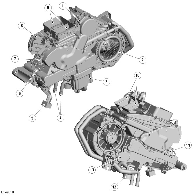
| ITEM | DESCRIPTION |
|---|---|
| 1 | Distribution motor |
| 2 | Blower |
| 3 | Isolation valve |
| 4 | Coolant pipes |
| 5 | Evaporator drain tube |
| 6 | Electrical connector for vehicle harness |
| 7 | Right temperature blend motor |
| 8 | Left temperature blend motor |
| 9 | Face distribution outlets (to headliner and C pillar vents) |
| 10 | Foot level distribution outlets (carpet vents under the seats) |
| 11 | Evaporator temperature sensor |
| 12 | Air conditioning pipe connector block |
| 13 | Blower control module |
The auxiliary climate control assembly is installed on the left side of the luggage compartment, behind the rear quarter trim panel. A grille in the trim panel allows air to flow from the luggage compartment into the auxiliary climate control assembly.
The auxiliary climate control assembly consists of a casing, formed from a pair of plastic moldings, which contains:
- An evaporator
- A heater core
- Temperature blend doors
- A distribution door
- A blower
- A blower control module
- An evaporator temperature sensor.
Refrigerant and coolant pipes from the engine compartment are connected to pipes from the evaporator and the heater core immediately below a seal plate in the rear left wheel arch. An evaporator drain tube, sealed with a foam rubber gasket, locates in the top of the left side member of the rear floor.
In the casing of the auxiliary climate control assembly, two parallel air steams flow from the blower through the evaporator and heater core to two pairs of distribution outlets. The left and right air streams supply the related rear zones of the passenger compartment. The front pair of distribution outlets supply the vents under the rear seats. The rear pair of distribution outlets supply the vents in the headliner and in the C pillar trim panels.
The left and right air streams each contain two temperature blend doors connected together with a link mechanism. Separate electric motors, installed on the rear of the casing, operate the temperature blend doors in each air stream to give independent temperature control for each rear climate zone.
The left and right air streams share a common distribution door installed below the distribution outlets. An electric motor, installed on the top of the casing, operates the distribution door.
A Local Interconnect Network (LIN) bus connects the distribution motor and the temperature blend motors in series with the HVAC. The motors are powered by feeds from the HVAC, and share a ground connection with the rear blower and rear blower control module.
The HVAC determines the positions of the distribution and temperature blend doors by using either their closed or open position as a datum and memorizing the steps that it drives the individual motors. Each time the HVAC is activated, it checks the memorized position of the motors against fixed values for the current distribution and temperature settings on the control panel. If there is an error, the HVAC calibrates the applicable motor, to re-establish the datums, by driving it fully closed or open before re-setting it to the nominal selected position. A calibration run can also be invoked using Land Rover approved diagnostic equipment.
BLOWER CONTROL MODULE

The blower consists of an open hub, centrifugal fan powered by an electric motor. Power for the blower is supplied from the rear blower relay in the Rear Junction Box (RJB) via the blower control module, which is installed in the left side of the auxiliary climate control assembly, immediately downstream of the blower. To control blower speed, the HVAC outputs a Pulse Width Modulation (PWM) signal to the blower control module to regulate the voltage of the blower power supply.
EVAPORATOR TEMPERATURE SENSOR
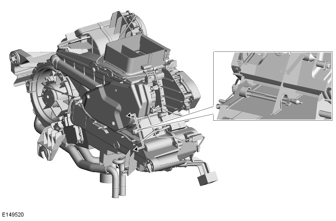
The evaporator temperature sensor is installed in the auxiliary climate control assembly on the downstream side of the evaporator. The evaporator temperature sensor is a Negative Temperature Coefficient (NTC) thermistor connected to the rear integrated control panel.
REFRIGERANT CIRCUIT
Low and high pressure pipes connect the front Air Conditioning (A/C) system to the auxiliary climate control assembly at a connector block in the left rear wheel arch, behind the wheel arch liner. On the auxiliary climate control assembly, pipes from the connector block are attached to an isolation valve on the evaporator.
AIR CONDITIONING PIPES
The A/C pipes consist of three sections of insulated pipe. The front and rear sections incorporate hoses at the ends that connect to the front A/C system and the auxiliary climate control assembly respectively. From the auxiliary climate control assembly, the A/C pipes are routed forward around the inboard side of the left rear wheel arch, then under the left edge of the floorpan to the rear of the left front wheel arch. The A/C pipes connect to the front climate control A/C system at a grommet in the wheel arch.
ISOLATION VALVE
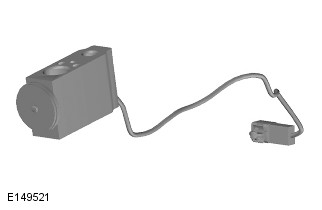
The isolation valve is a combined solenoid operated shut-off valve and block-type thermostatic expansion valve attached to the inlet and outlet pipes of the evaporator. The HVAC controls the operation of the shut-off valve to isolate the auxiliary climate control assembly from the front A/C system.
HEATER CIRCUIT
Supply and return coolant pipes connect the engine cooling system to the heater core pipes of the auxiliary climate control assembly in the left rear wheel arch, behind the wheel arch liner.
The coolant pipes consist of sections of insulated rigid pipes connected together with flexible hose joints. Quick release fittings connect the coolant pipes to the engine cooling system.
From the auxiliary climate control assembly, the coolant pipes are routed along the rear cross member and then forward under the right edge of the floorpan to the chassis longitudinal at the rear of the right front wheel arch liner.
DISTRIBUTION SYSTEM
The distribution system consists of a network of air ducts that supply air from the distribution outlets of the auxiliary climate control assembly to the vents installed in:
- The headliner, above each rear door
- The left and right C pillar trim panel
- The carpet, below the left and right rear seats.
The vents in the headliner, and in the C pillar trim panel are adjustable, those in the carpet are fixed.
Four duct air temperature sensors are installed in the air ducts. Two sensors are installed in the left and right upper air ducts, to measure the air temperature of the headliner, and C pillar trim panel outlets. Two sensors are fitted in the lower air ducts, to measure the air temperature of the outlets below the seats. The sensors are NTC thermistors, which are connected to the RICP. The HVAC uses the data from the sensors in output temperature calculations for the related ducts.
REAR INTEGRATED CONTROL PANEL
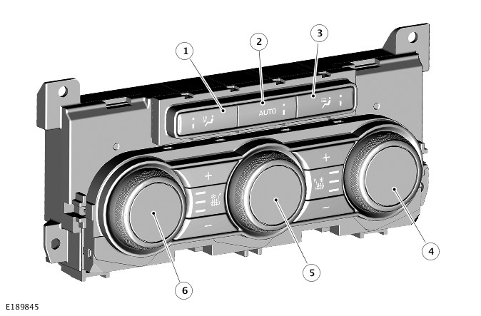
| ITEM | DESCRIPTION |
|---|---|
| 1 | Foot distribution switch |
| 2 | Automatic mode switch |
| 3 | Face distribution switch |
| 4 | Right temperature switch |
| 5 | Blower and on/off switch |
| 6 | Left temperature switch |
The RICP is installed in the rear of the floor console. The control panel contains rotary and push button switches for controlling the temperature, volume and distribution of air ro the rear seats. Each push switch contains an amber status Light Emitting Diode (LED). Display screens are integrated into the center of the rotary switches to display the selected temperature and blower speed as appropriate.
Additional push switches on the RICP are provided for control of seat heating/climate control seats.For additional information, refer to:Seats (501-10 Seating, Description and Operation).
The RICP has a permanent battery power feed from the Passenger Junction Box (PJB), and is connected to the High Speed (HS) Controller Area Network (CAN) Comfort bus. The RICP converts selections on the climate control switches into HS CAN Comfort messages, and transmits them to the HVAC. The RICP also receives inputs from the auxiliary climate system evaporator temperature sensor and four duct air temperature sensors. These inputs are also converted into HS CAN Comfort messages and transmitted to the HVAC Control Module.
For the auxiliary climate control system to operate, the engine must be running and automatic mode selected on the RICP or the Rear climate menu of the TS. The HVAC then illuminates the LED in the RICP AUTO switch, energizes the isolation valve and the rear blower, and operates the temperature blend and distribution motors to maintain the temperatures selected on the RICP. If the main climate control system is not already operating, the HVAC also activates the A/C compressor and operates the main climate control system in automatic mode.
Once the auxiliary climate control system is operating, the blower, distribution and temperature can be adjusted as required on the RICP or the Rear Climate menu of the touch screen. More than one distribution setting at a time may be selected to achieve the required air distribution.
The auxiliary climate control system can be selected off on the RICP, using the AUTO switch, or on the Rear Climate menu of the TS. The Rear Climate menu can also be used to lock the RICP to prevent operation of the auxiliary climate control system from the rear seats.
CONTROL DIAGRAM
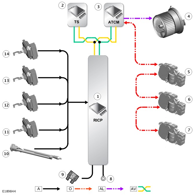
A = HARDWIRED; O = LOCAL INTERCONNECT NETWORK (LIN); AL = PULSE WIDTH MODULATION (PWM); AV = HIGH SPEED (HS) CONTROLLER AREA NETWORK (CAN) COMFORT BUS
| ITEM | DESCRIPTION |
|---|---|
| 1 | Rear Integrated Control Panel (RICP) |
| 2 | Touch Screen (TS) |
| 3 | HVAC Control Module |
| 4 | Blower Motor |
| 5 | Left temperature blend motor |
| 6 | Right temperature blend motor |
| 7 | Distribution motor |
| 8 | ground |
| 9 | Supply |
| 10 | Evaporator temperature sensor |
| 11 | Duct air temperature sensor |
| 12 | Duct air temperature sensor |
| 13 | Duct air temperature sensor |
| 14 | Duct air temperature sensor |
Removal and Installation
AUXILIARY CLIMATE CONTROL
ELECTRIC BOOSTER HEATER (G1618372)
- 80.20.05
- ELEMENT - POSITIVE TEMPERATURE CO-EFFICIENT (PTC) - RENEW
- RIGHT HAND DRIVE
- 1.40
- USED WITHINS
-
Removal steps in this procedure may contain installation details.
-
Some components shown removed for clarity.
-
Some variation in the illustrations may occur, but the essential information is always correct.
- Disconnect the battery ground cable.
Refer to:Specifications (414-00 Battery and Charging System - General Information, Specifications).
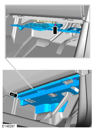
-
Refer to:Instrument Panel Lower Section (501-12 Instrument Panel and Console, Removal and Installation).
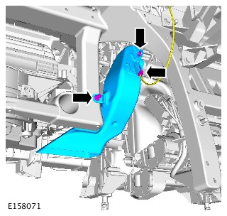
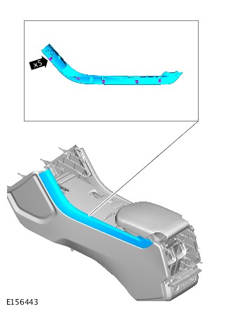
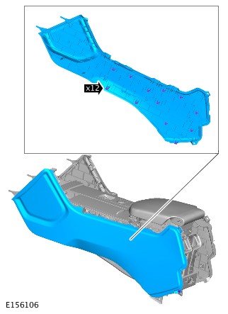
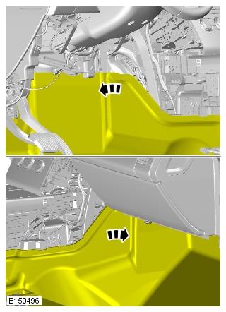
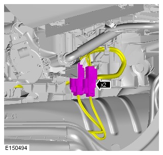
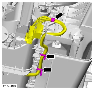


- To install, reverse the removal procedure.
AUXILIARY CLIMATE CONTROL
FUEL FIRED BOOSTER HEATER (G1521561)
- 80.40.01
- FUEL BURNING HEATER ASSEMBLY (FBH) - RENEW
- 3000 CC, TDV6
- 1.50
- USED WITHINS
- 80.20.05
- ELEMENT - POSITIVE TEMPERATURE CO-EFFICIENT (PTC) - RENEW
- RIGHT HAND DRIVE
- 1.40
- USED WITHINS
PART(S)
| STEP | PART NAME | QUANTITY |
|---|---|---|
| Installation Step 6 | Engine compartment brace bolts | 8 |
- This procedure contains some variation in the illustrations depending on the vehicle specification, but the essential information is always correct.
- This procedure contains illustrations showing certain components removed to provide extra clarity.
- Disconnect the startup battery ground cable.
Refer to:Specifications (414-00 Battery and Charging System - General Information, Specifications).
- Raise and support the vehicle on a suitable 2 post lift.
Refer to:Lifting (100-02 Jacking and Lifting, Description and Operation).
- Drain the cooling system.
Refer to:Cooling System Partial Draining and Vacuum Filling (303-03A Engine Cooling - TDV6 3.0L Diesel /TDV6 3.0L Diesel - Gen 1.5/TDV6 3.0L Diesel - Gen 2, General Procedures).Refer to:Cooling System Partial Draining and Vacuum Filling (303-03B Engine Cooling - V6 S/C 3.0L Petrol, General Procedures).Refer to:Cooling System Partial Draining and Vacuum Filling (303-03C Engine Cooling - V8 S/C 5.0L Petrol, General Procedures).Refer to:Cooling System Partial Draining and Vacuum Filling (303-03F Engine Cooling - TDV8 4.4L Diesel, General Procedures).Refer to:Cooling System Partial Draining and Vacuum Filling (303-03G Engine Cooling - INGENIUM I4 2.0L Diesel, General Procedures).
- Remove the cowl panel.
Refer to:Cowl Panel Grille (501-02 Front End Body Panels, Removal and Installation).
- Remove the front right wheel arch liner.
Refer to:Fender Splash Shield (501-02 Front End Body Panels, Removal and Installation).
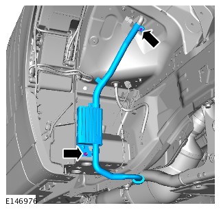
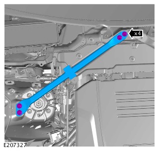
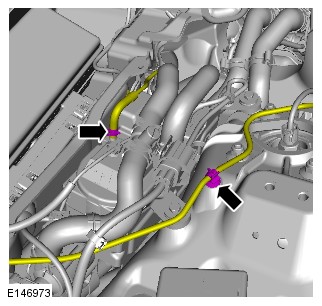

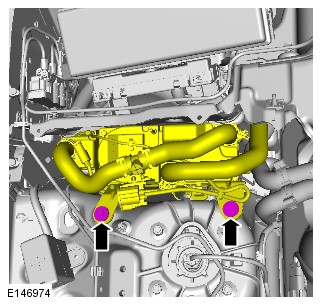

-
- Install the Fuel Fired Booster Heater (FFBH).
- Connect the 4 coolant hoses.
- Install the clip.
- Install and tighten the 2 bolts.
Torque: 10Nm
-
- Connect the 2 electrical connectors.
- Install the clip.
-
- Connect the FFBH fuel line.
- Install the clip.
-
- Install the right engine compartment brace.
- Install and tighten the 4 bolts.
Torque: 55Nm
-
- Install the FFBH exhaust assembly.
- Install and tighten the 2 bolts.
Torque: 10Nm
- Install the front right wheel arch liner.
Refer to:Fender Splash Shield (501-02 Front End Body Panels, Removal and Installation).
- Install the cowl panel.
Refer to:Cowl Panel Grille (501-02 Front End Body Panels, Removal and Installation).
- Fill the cooling system.
Refer to:Cooling System Partial Draining and Vacuum Filling (303-03A Engine Cooling - TDV6 3.0L Diesel /TDV6 3.0L Diesel - Gen 1.5/TDV6 3.0L Diesel - Gen 2, General Procedures).Refer to:Cooling System Partial Draining and Vacuum Filling (303-03B Engine Cooling - V6 S/C 3.0L Petrol, General Procedures).Refer to:Cooling System Partial Draining and Vacuum Filling (303-03C Engine Cooling - V8 S/C 5.0L Petrol, General Procedures).Refer to:Cooling System Partial Draining and Vacuum Filling (303-03F Engine Cooling - TDV8 4.4L Diesel, General Procedures).Refer to:Cooling System Partial Draining and Vacuum Filling (303-03G Engine Cooling - INGENIUM I4 2.0L Diesel, General Procedures).
- Connect the startup battery ground cable.
Refer to:Specifications (414-00 Battery and Charging System - General Information, Specifications).
- Connect the Land Rover approved diagnostic equipment to the vehicle and complete the FFBH activation test.
AUXILIARY CLIMATE CONTROL
FUEL FIRED BOOSTER HEATER COOLANT PUMP (G1521563)
- 80.40.28
- AUXILIARY COOLANT PUMP - RENEW
- 3000 CC, TDV6
- 1.70
- USED WITHINS
Removal steps in this procedure may contain installation details.
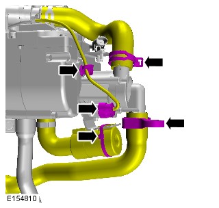
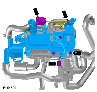

- To install, reverse the removal procedure.
AUXILIARY CLIMATE CONTROL
FUEL FIRED BOOSTER HEATER FLAME SENSOR (G1521577)
- 80.40.35
- SENSOR - FLAME - FUEL FIRED BOOSTER HEATER (FFBH) - RENEW
- 3000 CC, TDV6
- 2.00
- USED WITHINS
Removal steps in this procedure may contain installation details.
- Remove the fuel fired booster heater combustion chamber.
Refer to:Fuel Fired Booster Heater Combustion Chamber (412-02 Auxiliary Climate Control, Removal and Installation).


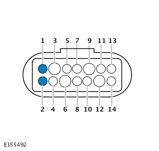
- To install, reverse the removal procedure.
AUXILIARY CLIMATE CONTROL
FUEL FIRED BOOSTER HEATER FUEL PUMP (G1605926)
- 80.40.40
- PUMP - FUEL - RENEW
- 3000 CC, TDV6
- 0.50
- USED WITHINS
- 80.40.40
- PUMP - FUEL - RENEW
- NO OCCASIONAL SEATS FITTED
- 0.40
- USED WITHINS
-
Before disconnecting any components, make sure the area is clean and free from foreign material. When disconnected all openings must be sealed.
-
If a new fuel pump is to be installed, make sure that the blanking caps are not removed prior to installation.
Removal steps in this procedure may contain installation details.
-
Refer to:Diesel Fuel System Health and Safety Precautions (100-00 General Information, Description and Operation).Refer to:Petrol and Petrol-Ethanol Fuel Systems Health and Safety Precautions (100-00 General Information, Description and Operation).
- Disconnect the battery ground cable.
Refer to:Specifications (414-00 Battery and Charging System - General Information, Specifications).
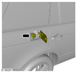
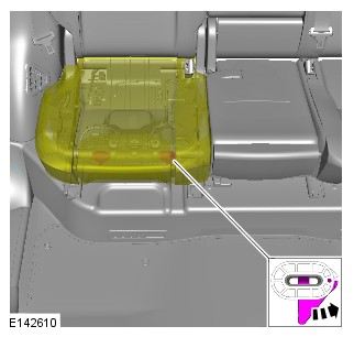
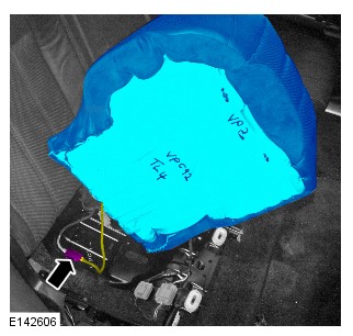

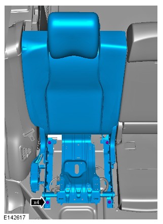

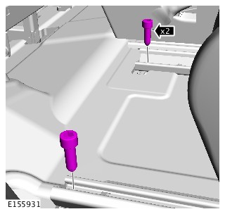
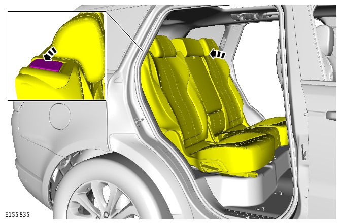
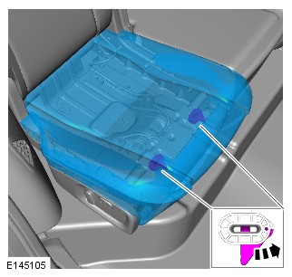
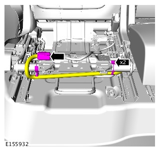
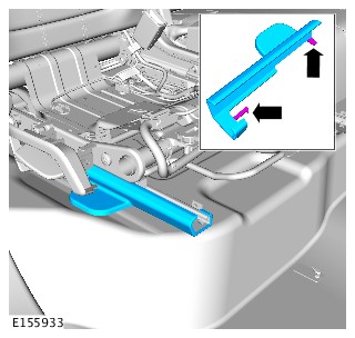
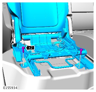
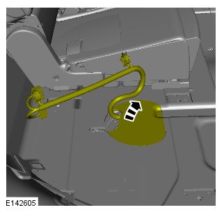
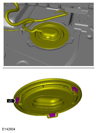
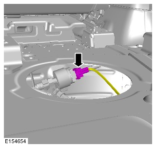
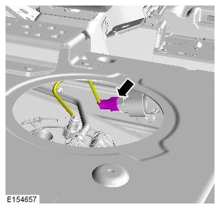
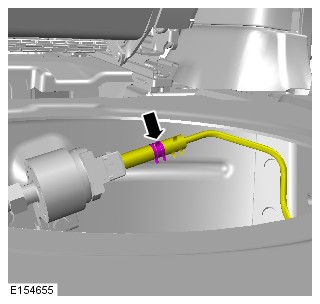
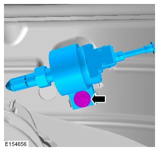
-
To install, reverse the removal procedure.NOTE:
Make sure that the fuel pipes do not contact the vehicle body.
AUXILIARY CLIMATE CONTROL
FUEL FIRED BOOSTER HEATER GLOW PLUG (G1521571)
- 80.40.08
- GLOW PLUG - FUEL FIRED BOOSTER HEATER (FFBH) - RENEW
- 3000 CC, TDV6
- 1.90
- USED WITHINS
Removal steps in this procedure may contain installation details.
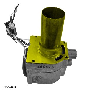
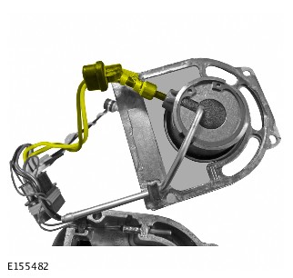
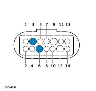
- To install, reverse the removal procedure.
UXILIARY CLIMATE CONTROL
AUXILIARY BLOWER MOTOR (G1620935)
- 82.26.33
- BLOWER MOTOR - ASSEMBLY - RENEW
- 3000 CC, TDV6
- 2.10
- USED WITHINS
-
Removal steps in this procedure may contain installation details.
-
Some variation in the illustrations may occur, but the essential information is always correct.
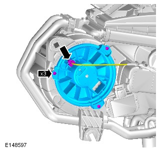
- To install, reverse the removal procedure.
AUXILIARY CLIMATE CONTROL
AUXILIARY BLOWER MOTOR RESISTOR (G1620936)
- 82.26.40
- RELAY - BLOWER MOTOR - RENEW
- 3000 CC, TDV6
- 2.10
- USED WITHINS
-
Removal steps in this procedure may contain installation details.
-
Some variation in the illustrations may occur, but the essential information is always correct.
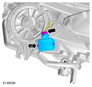
- To install, reverse the removal procedure.
AUXILIARY CLIMATE CONTROL
AUXILIARY CLIMATE CONTROL FACE/FEET MOTOR (G1620937)
- 82.26.34
- MOTOR - AIR DISTRIBUTION DOOR - RENEW
- ALL DERIVATIVES
- 0.30
- USED WITHINS
-
Removal steps in this procedure may contain installation details.
-
Some variation in the illustrations may occur, but the essential information is always correct.
- Disconnect the battery ground cable.
Refer to:Specifications (414-00 Battery and Charging System - General Information, Specifications).
-
Refer to:Left Loadspace Trim Panel (501-05 Interior Trim and Ornamentation, Removal and Installation).
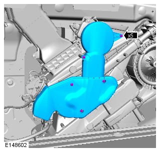


- To install, reverse the removal procedure.
AUXILIARY CLIMATE CONTROL
AUXILIARY HEATER CORE (G1620938)
- 82.26.19
- MATRIX - HEATER - REAR CLIMATE CONTROL - RENEW
- 3000 CC, TDV6
- 2.10
- USED WITHINS
-
Removal steps in this procedure may contain installation details.
-
Some variation in the illustrations may occur, but the essential information is always correct.
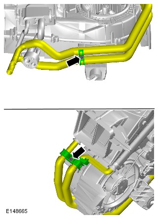
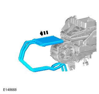
- To install, reverse the removal procedure.
AUXILIARY CLIMATE CONTROL
AUXILIARY HEATER CORE AND EVAPORATOR CORE HOUSING (G1620939)
- 82.26.22
- HEATER/COOLER UNIT - REAR CLIMATE CONTROL - RENEW
- 3000 CC, TDV6
- 2.10
- USED WITHINS
PART(S)
| STEP | PART NAME | QUANTITY |
|---|---|---|
| Removal Step 6 | Evaporator pipe O-ring seals | 1 |
Before disconnecting any components, make sure the area is clean and free from foreign material. When disconnected all openings must be sealed.
-
Removal steps in this procedure may contain installation details.
-
Some variation in the illustrations may occur, but the essential information is always correct.
-
Raise and support the vehicle.WARNING:
Make sure to support the vehicle with axle stands.
-
Refer to:Cooling System Partial Draining and Vacuum Filling (303-03 Engine Cooling - TDV6 3.0L Diesel, General Procedures).
-
Refer to:Air Conditioning System Recovery, Evacuation and Charging (412-00 Climate Control System - General Information, General Procedures).
- Disconnect the battery ground cable.
Refer to:Specifications (414-00 Battery and Charging System - General Information, Specifications).
-
Refer to:Rear Fender Splash Shield (501-08 Exterior Trim and Ornamentation, Removal and Installation).
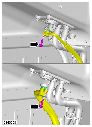
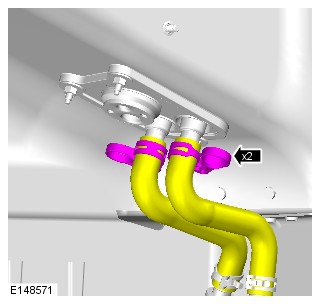
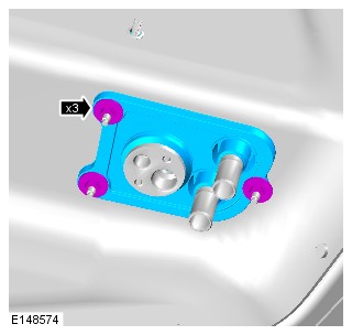
-
Refer to:Left Loadspace Trim Panel (501-05 Interior Trim and Ornamentation, Removal and Installation).
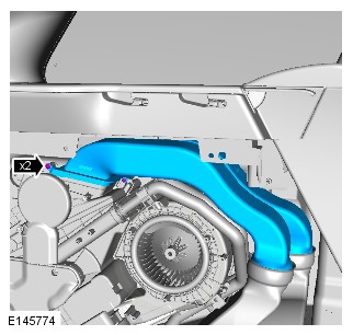
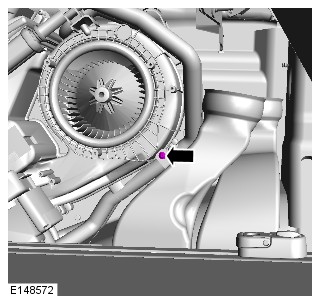
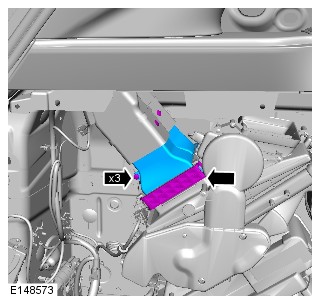
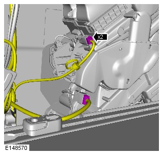

-
To install, reverse the removal procedure.NOTE:
Remove and discard all blanking caps.
AUXILIARY CLIMATE CONTROL
FUEL FIRED BOOSTER HEATER OVERHEAT SENSOR (G1604773)
- 80.40.09
- HEAT EXCHANGER - FUEL FIRED BOOSTER HEATER (FFBH) - RENEW
- 3000 CC, TDV6
- 1.90
- USED WITHINS
- 80.40.34
- SENSOR - OVERHEAT - FUEL FIRED BOOSTER HEATER (FFBH) - RENEW
- 3000 CC, TDV6
- 1.90
- USED WITHINS
Removal steps in this procedure may contain installation details.
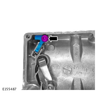
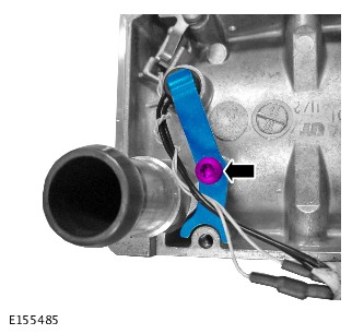
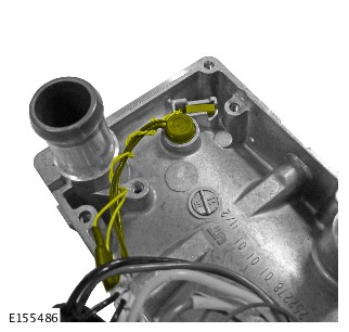
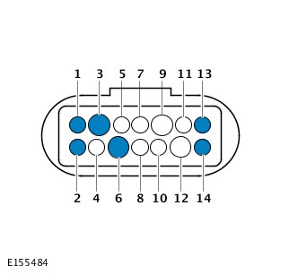
- To install, reverse the removal procedure.
AUXILIARY CLIMATE CONTROL
FUEL FIRED BOOSTER HEATER HEAT EXCHANGER (G1604772)
- 80.40.09
- HEAT EXCHANGER - FUEL FIRED BOOSTER HEATER (FFBH) - RENEW
- 3000 CC, TDV6
- 1.90
- USED WITHINS
Removal steps in this procedure may contain installation details.

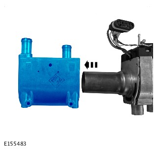
- To install, reverse the removal procedure.
AUXILIARY CLIMATE CONTROL
FUEL FIRED BOOSTER HEATER COMBUSTION CHAMBER (G1604770)
- 80.40.13
- COMBUSTION CHAMBER - FUEL FIRED BOOSTER HEATER (FFBH) - RENEW
- 3000 CC, TDV6
- 1.90
- USED WITHINS
Removal steps in this procedure may contain installation details.
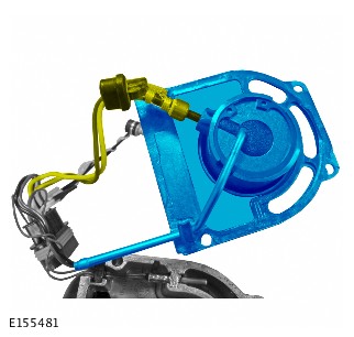
- To install, reverse the removal procedure.
AUXILIARY CLIMATE CONTROL
FUEL FIRED BOOSTER HEATER BLOWER (G1604769)
- 80.40.14
- BLOWER MOTOR - FUEL FIRED BOOSTER HEATER (FFBH) - RENEW
- 3000 CC, TDV6
- 2.10
- USED WITHINS
Removal steps in this procedure may contain installation details.

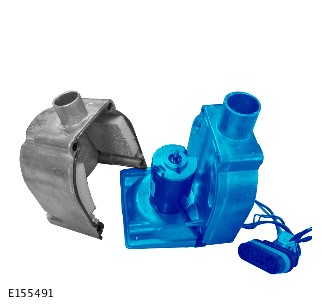

- To install, reverse the removal procedure.
AUXILIARY CLIMATE CONTROL
FUEL FIRED BOOSTER HEATER CONTROL MODULE (G1604771)
- 80.40.36
- CONTROL MODULE - FUEL FIRED BOOSTER HEATER (FFBH) - RENEW
- 3000 CC, TDV6
- 1.80
- USED WITHINS
- 80.40.13
- COMBUSTION CHAMBER - FUEL FIRED BOOSTER HEATER (FFBH) - RENEW
- 3000 CC, TDV6
- 1.90
- USED WITHINS
Removal steps in this procedure may contain installation details.