Range Rover Sport / L494 2017 EXHAUST SYSTEM MANUAL
309-00A: Exhaust System - TDV6 3.0L Diesel - Gen 2
EXHAUST SYSTEM - TDV6 3.0L DIESEL - GEN 2 (G1509407)
Lubricants, Fluids, Sealers and Adhesives
| SPECIFICATIONS | |
|---|---|
| Heated Oxygen Sensor (HO2S) thread lubricant | ESE-M12A4-A |
| Exhaust gas temperature sensor thread lubricant | ESE-M12A4-A |
| Particulate matter sensor thread lubricant | ESE-M12A4-A |
| Selective Catalyst Reduction (SCR) NOx sensor thread lubricant | ESE-M12A4-A |
Torque Specifications
| ITEM | NM | LB-FT | LB-IN |
|---|---|---|---|
| Selective Catalyst Reduction (SCR) NOx sensor | 48 | 35 | - |
| Particulate matter sensor | 48 | 35 | - |
| Exhaust gas temperature sensor | 35 | 26 | - |
| Heated Oxygen Sensor (HO2S) | 48 | 35 | - |
| Exhaust mass dumper | 22 | 16 | - |
| Diesel Exhaust Fluid (DEF) injector | 5 | - | 44 |
| Exhaust system to exhaust manifold bolts | 28 | 21 | - |
| Exhaust gas recirculation (EGR) to Diesel Particulate Filter (DPF) pipe clamp | 9 | - | 80 |
| Particulate matter sensor module bolt | 10 | 7 | - |
| SCR NOx sensor module bolt | 10 | 7 | - |
| Body side undershield bolts | 9 | - | 80 |
| Body side undershield nuts | 9 | - | 80 |
| Body side undershield screw | 2.8 | - | 25 |
| DEF tank cover bolt | 12 | 9 | - |
| DPF to SCR clamp | 55 | 35 | - |
| Transmission undershield M10 bolt | 60 | 44 | - |
| Transmission undershield M6 bolt | 10 | 7 | - |
Description and Operation
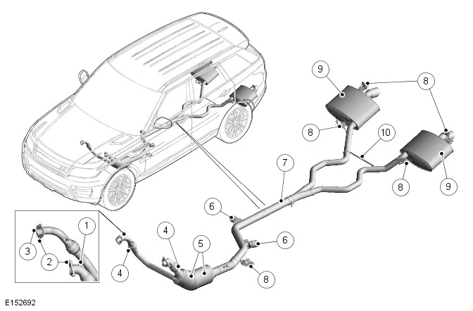
EXHAUST SYSTEM - TDV6 3.0L DIESEL - GEN 2 (G1728613)
| ITEM | DESCRIPTION |
|---|---|
| 1 | HO2S Mounting Boss |
| 2 | Bolts (5 Off) |
| 3 | Gasket |
| 4 | Flexible Coupling |
| 5 | Catalytic converter |
| 6 | Mass Damper (2 Off) |
| 7 | Clamp |
| 8 | Mounting rubber (5 Off) |
| 9 | Rear silencer |
| 10 | Exhaust brace |

| ITEM | DESCRIPTION |
|---|---|
| 1 | Bolts (5 Off) |
| 2 | Gasket |
| 3 | HO2S Mounting Boss |
| 4 | Clamp |
| 5 | Hanger bar |
| 6 | Silencer - Rear |
| 7 | Exhaust Brace |
| 8 | Exhaust pressure control valve |
| 9 | Mass Damper (2 Off) |
| 10 | Differential Pressure Sensor |
| 11 | Diesel Particulate Filter |
| 12 | Catalytic Converter |
| 13 | Flexible Coupling |
| 14 | Exhaust Gas Temperature Sensor Mounting Boss |
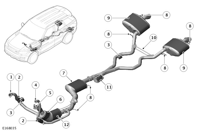
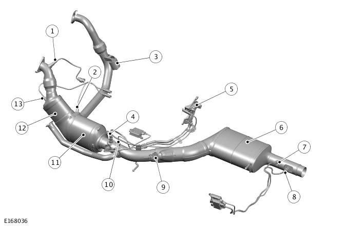
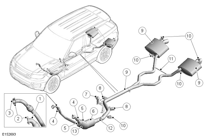
| ITEM | DESCRIPTION |
|---|---|
| 1 | Flange connection - Secondary turbocharger |
| 2 | Flexible coupling |
| 3 | Mass damper |
| 4 | Flange connection – Low Pressure Exhaust Gas Recirculation (LPEGR) valve |
| 5 | Flange connection - Primary turbocharger |
| 6 | Catalytic converter |
| 7 | Selective Catalytic Reduction (SCR) catalytic converter |
| 8 | Hanger bar |
| 9 | Rear silencer |
| 10 | Exhaust brace |
| 11 | Exhaust pressure control valve |
| 12 | Diesel Particulate Filter (DPF) |
There are three variants that are available on the TDV6 3.0L Exhaust System:
- Non DPF System – EU4 Emission regulations.
- DPF System – EU5 Emissions regulations.
- DPF System with SCR System – EU6 Emission regulations.
On vehicles with a DPF fitted, a single catalytic converter is located in the bank 2 exhaust downpipe from the manifold. On vehicles without a DPF, a second catalytic converter is fitted in place of the DPF.
On vehicles with SCR System fitted, an additional SCR catalytic converter is located in the exhaust downpipe after the DPF.
The system is attached to the underside of the body with 5 mounting rubbers which are located on hanger brackets that are welded to the system.
The mounting rubbers locate on corresponding hanger brackets which are bolted to the underside of the vehicle body.
-
The use of bio fuels can seriously contaminate and destroy the coatings used on the catalytic converter. The DPF and the catalytic converter can become irreversibly contaminated if non-specified oils or fuels are used. This can result in the vehicle being unable to regenerate the DPF, becoming non-compliant with the rear silencers emission regulations and replacement of the catalytic converter and DPF will be required.
-
If the vehicle is waded in deep water and the engine is stopped with the rear silencers submerged, the water, which can enter the system, can also contaminate both the DPF and catalytic converter. This can result in catalytic converter damage and damaging the ability for the DPF to regenerate therefore requiring both components to be replaced.
FRONT SECTION
The front section comprises of two catalytic converters or, if a DPF is fitted, one catalytic converter and diesel particulate filter. The bank 2 inlet pipe connects to the catalytic converter and bank 1 inlet pipe will connect to a half shell that is located between the two catalytic converters or catalytic converter and diesel particulate filter (if DPF fitted).
On vehicles with SCR System fitted, an additional SCR catalytic converter is located in the front section after the DPF.
Each inlet pipe is fitted with a flange that connects to the turbocharger for each cylinder bank. The bank 2 inlet flange uses a 3 bolt fixing and the bank 1 inlet flange uses a 2 bolt fixing that are screwed into threaded holes in each of the turbochargers. Each flange is sealed using a gasket and both inlet pipes are fitted with flexible couplings.
The catalytic converters or DPF (if fitted) have an outlet pipe that is secured by a clamp to the centre section. The outlet pipe has 2 mass dampers which will absorb resonance from the system. The outlet pipe also has one hanger bracket which is welded to the pipe.
REAR SECTION
The rear section comprises a single pipe, which separates into two pipes that connect to the rear silencers. The rear section is connected to the front section with a torca clamp.
The two rear silencers are attached to the body by two exhaust hanger brackets on each of the rear silencers.
A brace is welded between the pipes to retain system in position and reduce exhaust flexing.
CATALYTIC CONVERTER
The oxidizing catalytic converter is located in the front section of the bank 2 inlet pipe, after the pre-catalyst exhaust temperature sensor (vehicles with DPF only) and the Heated Oxygen Sensor (HO2S).
On vehicles fitted with DPF: The Pre and Post DPF Temperature Sensors are used by the engine management system to monitor the DPF regeneration purposes.
On vehicles without a DPF, a second catalytic converter is fitted in place of the DPF.
The engine management system provides accurately metered quantities of fuel to the combustion chambers to ensure the most efficient use of fuel and to minimise the exhaust emissions. On vehicles without a DPF, the second catalytic converter is fitted to further reduce the carbon monoxide and the hydrocarbon content of the gases. In the catalytic converter the exhaust gases are passed through honeycombed ceramic elements coated with a special surface treatment called ‘washcoat’. The 'washcoat' increases the surface area of the ceramic elements by a factor of approximately 7000. The 'washcoat' is a coating containing platinum and palladium, which are active constituents for converting harmful emissions into inert by-products. The platinum and palladium catalytically oxidise the carbon monoxide and the hydrocarbons in the exhaust gases, and converts them into carbon dioxide and water.
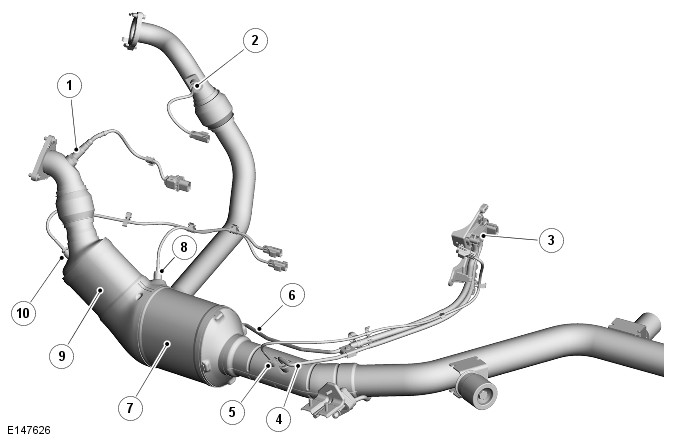
DIESEL PARTICULATE FILTER
| ITEM | DESCRIPTION |
|---|---|
| 1 | Heated Oxygen Sensor |
| 2 | Pre-DPF Temperature Sensor |
| 3 | Differential Pressure Sensor |
| 4 | Low Pressure Pipe |
| 5 | Post-DPF Temperature Sensor |
| 6 | High Pressure Pipe |
| 7 | Diesel Particulate Filter |
| 8 | Post-Catalyst Temperature Sensor |
| 9 | Catalytic Converter |
| 10 | Pre-Catalyst Temperature Sensor |
For additional information, refer to:Diesel Particulate Filter (309-00D Exhaust System - TDV8 4.4L Diesel, Description and Operation).
SELECTIVE CATALYST REDUCTION SYSTEM
| ITEM | DESCRIPTION |
|---|---|
| 1 | Heated Oxygen Sensor (HO2S) |
| 2 | Pre DPF exhaust gas temperature sensor |
| 3 | Mass damper (Bi-Turbocharger vehicles only) |
| 4 | Pre Selective Catalyst Reduction NOx sensor |
| 5 | Differential pressure sensor |
| 6 | Selective Catalyst Reduction (SCR) catalytic converter |
| 7 | Post Selective Catalyst Reduction soot sensor |
| 8 | Post Selective Catalyst Reduction NOx sensor |
| 9 | DEF Dosing Module |
| 10 | Post DPF exhaust gas temperature sensor |
| 11 | Diesel Particulate Filter (DPF) |
| 12 | Catalytic converter |
| 13 | Pre-Catalyst Temperature Sensor |
For additional information, refer to:Selective Catalyst Reduction (309-00A Exhaust System - TDV6 3.0L Diesel - Gen 2, Description and Operation).
EXHAUST SYSTEM - TDV6 3.0L DIESEL - GEN 2
DIESEL PARTICULATE FILTER - COMPONENT LOCATION (G1728614)
| ITEM | DESCRIPTION |
|---|---|
| 1 |
HO2S Mounting Boss
|
| 2 |
Bolts (5 Off)
|
| 3 |
Gasket
|
| 4 |
Flexible coupling
|
| 5 |
Exhaust Gas Temperature Sensor (EGTS) mounting boss
|
| 6 |
Diesel Particulate Filter (DPF)
|
| 7 |
Differential pressure sensor
|
| 8 |
Mass Damper (2 Off)
|
| 9 |
Clamp
|
| 10 |
Mounting Rubber (5 Off)
|
| 11 |
Exhaust Brace
|
| 12 |
Exhaust Gas Temperature Sensor (EGTS) mounting boss
|
| 13 |
Catalytic Converter
|
| ITEM | DESCRIPTION |
|---|---|
| 1 |
Heated Oxygen Sensor
|
| 2 |
Pre-DPF Temperature Sensor
|
| 3 |
Differential Pressure Sensor
|
| 4 |
Low Pressure Pipe
|
| 5 |
Post-DPF Temperature Sensor
|
| 6 |
High Pressure Pipe
|
| 7 |
Diesel Particulate Filter
|
| 8 |
Post-Catalyst Temperature Sensor
|
| 9 |
Catalytic Converter
|
| 10 |
Pre-Catalyst Temperature Sensor
|
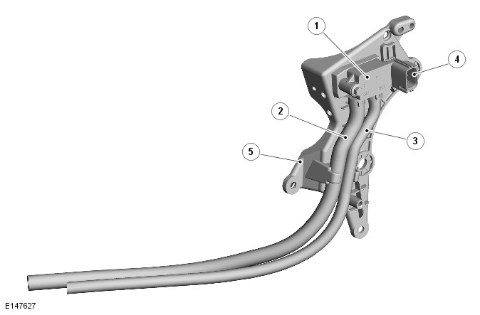
| ITEM | DESCRIPTION |
|---|---|
| 1 |
Differential Pressure Sensor
|
| 2 |
High Pressure Pipe
|
| 3 |
Low Pressure Pipe
|
| 4 |
Electrical Connector
|
| 5 |
Bracket
|
EXHAUST SYSTEM - TDV6 3.0L DIESEL - GEN 2
DIESEL PARTICULATE FILTER - SYSTEM OPERATION AND COMPONENT DESCRIPTION (G1478880)
Two processes are used to regenerate the Diesel Particulate Filter (DPF); passive and active.
Passive Regeneration
Passive regeneration requires no special engine management intervention and occurs during normal engine operation. The passive regeneration involves a slow conversion of the particulate matter deposited in the DPF into carbon dioxide. This process occurs when the DPF temperature exceeds 250°C (482°F) and is a continuous process when the vehicle is being driven at higher engine loads and speeds.
During passive regeneration, only a portion of the particulate matter is converted into carbon dioxide. This is because the chemical reaction, which utilises nitrogen dioxide, is slower than the rate of engine production of particulate matter and is effective from 250°C (482°F).
Above 580°C the conversion efficiency of the particulate into carbon dioxide rapidly increases. These temperatures are generally only be achieved using the active regeneration process.
Active Regeneration
Active regeneration starts when the particulate loading of the DPF reaches a threshold as monitored or determined by the DPF control software. The threshold calculation is based on driving style, distance travelled and back pressure signals from the differential pressure sensor.
Active regeneration generally occurs every 250 miles (400 km) although this is dependant on how the vehicle is driven. For example, if the vehicle is driven at low loads in urban traffic regularly, active regeneration will occur more often. This is due to the rapid build-up of particulate in the DPF than if the vehicle is driven at high speeds when passive regeneration will have occurred.
The DPF software incorporates a mileage trigger which is used as back-up for active regeneration. If active regeneration has not been initiated by a back pressure signal from the differential pressure sensor, regeneration is requested based on distance travelled.
Active regeneration of the DPF is commenced when the temperature of the DPF is increased to the combustion temperature of the particles. The DPF temperature is raised by increasing the exhaust gas temperature. This is achieved by introducing post-injection of fuel after the pilot and main fuel injections have occurred.
It is determined by the DPF software monitoring the signals from the two DPF temperature sensors to establish the temperature of the DPF. Depending on the DPF temperature, the DPF software requests the Engine Control Module (ECM) to perform either one or two post-injections of fuel:
- The first post-injection of fuel retards combustion inside the cylinder which increases the temperature of the exhaust gas.
- The second post-injection of fuel is injected late in the power stroke cycle. The fuel partly combusts in the cylinder, but some unburnt fuel also passes into the exhaust where it creates an exothermic event within the catalytic converter, further increasing the temperature of the DPF.
The active regeneration process takes up to 20 minutes to complete. The first phase increases the DPF temperature to 500°C (932°F). The second phase further increases the DPF temperature to 600°C (1112°F) which is the optimum temperature for particle combustion. This temperature is then maintained for 15-20 minutes to ensure complete oxidation of the particles within the DPF. The oxidation process converts the carbon particles to carbon dioxide.
The active regeneration temperature of the DPF is closely monitored by the DPF software to maintain a target temperature of 600°C (1112°F) at the DPF inlet. The temperature control ensures that the temperatures do not exceed the operational limits of the turbocharger and the catalytic converter. The turbocharger inlet temperature must not exceed 830°C (1526°F) and the catalytic converter brick temperature must not exceed 800°C (1472°F) and the exit temperature must remain below 875°C (1382°F).
During the active regeneration process the following ECM controlled events occur:
- The turbocharger is maintained in the fully open position. This minimizes heat transmission from the exhaust gas to the turbocharger and reduces the rate of exhaust gas flow allowing optimum heating of the DPF. If the driver demands an increase in engine torque, the turbocharger will respond by closing the vanes as necessary.
- The throttle is closed as this assists in increasing the exhaust gas temperature and reduces the rate of exhaust gas flow which has the effect of reducing the time for the DPF to reach the optimum temperature.
- The Exhaust Gas Recirculation (EGR) valve is closed. The use of EGR decreases the exhaust gas temperature and therefore prevents the optimum DPF temperature being achieved.
If, due to vehicle usage and/or driving style, the active regeneration process cannot take place or is unable to regenerate the DPF, the dealer can force regenerate the DPF. This is achieved by either driving the vehicle until the engine is at its normal operating temperature and then driving for a further 20 minutes at speeds of not less than 30 mph (48 km/h).
DPF Control
The DPF requires constant monitoring to ensure that it is operating at its optimum efficiency and does not become blocked. The ECM contains DPF software which controls the monitoring and operation of the DPF system and also monitors other vehicle data to determine regeneration periods and service intervals.
The DPF software can be divided into three separate control software modules; a DPF supervisor module, a DPF fuel management module and a DPF air management module.
These three modules are controlled by a fourth software module known as the DPF co-ordinator module. The co-ordinator module manages the operation of the other modules when an active regeneration is requested.
DPF Fuel Management Module
The DPF fuel management module controls the following functions:
- Timing and quantity of the four split injections per stroke (pilot, main and two post injections).
- Injection pressure and the transition between the three different calibration levels of injection.
The above functions are dependant on the condition of the catalytic converter and the DPF.
The controlled injection determines the required injection level in addition to measuring the activity of the catalytic converter and the DPF. The fuel management calculates the quantity and timing for the four split injections, for each of the three calibration levels for injection pressure, and also manages the transition between the levels.
The two post injections are required to separate the functionality of increasing in-cylinder gas temperatures and the production of hydrocarbons. The first post injection is used to generate the higher in-cylinder gas temperature while simultaneously retaining the same engine torque output produced during normal (non-regeneration) engine operation. The second post injection is used to generate hydrocarbons by allowing unburnt fuel into the catalytic converter without producing increased engine torque.
DPF Air Management Module
The DPF air management module controls the following functions:
- EGR control
- Turbocharger boost pressure control
- Intake air temperature and pressure control.
During active regeneration, the EGR operation is disabled -except for overrun conditions - and the closed-loop activation of the turbocharger boost controller is calculated. The air management module controls the air in the intake manifold to a predetermined level of pressure and temperature. This control is required to achieve the correct in-cylinder conditions for stable and robust combustion of the post injected fuel.
The module controls the intake air temperature by actuating the EGR throttle and by adjustment of the turbocharger boost pressure control.
DPF Co-ordinator Module
The DPF co-ordinator module reacts to a regeneration request from the supervisor module by initiating and co-ordinating the following DPF regeneration requests:
- EGR cut-off - except for overrun condition
- Turbocharger boost pressure control
- Engine load increase
- Control of air pressure and temperature in the intake manifold
- Fuel injection control.
When the supervisor module issues a regeneration request, the co-ordinator module requests EGR cut-off and a regeneration specific turbocharger boost pressure control. It then waits for a feedback signal from the EGR system confirming that the EGR valve is closed.
When the EGR valve is closed, the co-ordinator module initiates requests to increase engine load by controlling the intake air temperature and pressure.
Once confirmation is received that intake conditions are controlled or a calibration time has expired, the co-ordinator module then changes to a state awaiting an accelerator pedal release manoeuvre from the driver. If this occurs or a calibration time has expired, the co-ordinator module generates a request to control fuel injections to increase exhaust gas temperature.
As the amount of particulate trapped by the DPF increases, the pressure at the inlet side of the DPF increases in comparison to the DPF outlet. The DPF software uses this comparison, in conjunction with other data, to calculate the accumulated amount of trapped particulate.
By measuring the pressure difference between the DPF inlet and outlet and the DPF temperature, the DPF software can determine if the DPF is becoming blocked and requires regeneration.
The DPF system reduces diesel particulate emissions to negligible levels to meet current European stage 5 emission standards.
The particulate emissions are the black fumes emitted from the diesel engine under certain load conditions. The emissions are a complex mixture of solid and liquid components with the majority of the particulate being carbon microspheres on which hydrocarbons from the engine's fuel and lubricant condense.
The DPF system comprises the following components:
- Diesel Particulate Filter (DPF)
- DPF control software incorporated in the ECM
- Differential pressure sensor.
The DPF is located in the exhaust system, downstream of the catalytic converter. Its function is to trap particulate matter in the exhaust gases leaving the engine. A major feature of the DPF is its ability for regeneration. Regeneration is the burning of particulate trapped by the filter to prevent obstruction to the free flow of exhaust gasses. The regeneration process takes place at calculated intervals and is not noticeable by the driver of the vehicle.
Regeneration is most important, since an overfilled filter can damage the engine through excessive exhaust back pressure and can itself be damaged or destroyed. The material trapped in the filter is in the most part carbon particles with some absorbed hydrocarbons.
The DPF uses a filter technology based on a filter with a catalytic coating. The DPF is made from silicon carbide housed in a steel container and has excellent thermal shock resistance and thermal conductivity properties. The DPF is designed for the engine's operating requirements to maintain the optimum back pressure requirements.
The porous surface of the filter consists of thousands of small parallel channels positioned in the longitudinal direction of the exhaust system. Adjacent channels in the filter are alternately plugged at the end. This design forces the exhaust gasses to flow through the porous filter walls, which act as the filter medium. Particulate matter which are too big to pass through the porous surface are collected and stored in the channels.
The collected particulate matter, if not removed, can create an obstruction to exhaust gas flow. The stored particles are removed by a regeneration process which incinerates the particles.
Diesel Particulate Filter (DPF) Temperature Sensors
The DPF temperature sensors are used to provide exhaust gas temperature feedback to the Engine Control Module (ECM) in order to control engine conditions and to effectively monitor and control emissions.
The DPF temperature sensor's information is sent to the ECM using a 0 to 5V signal (lower voltage being higher temperature and higher voltage being lower temperature).
The information is used, in conjunction with other data, to estimate the amount of accumulated particulates and to control the DPF temperature.
Instrument Cluster (IC) Indications
For drivers who make regular short journeys at low speeds, it may not be possible to efficiently regenerate the DPF. In this case, the DPF software will detect a blockage of the DPF from signals from the differential pressure sensor and will alert the driver as follows:
The driver will be alerted to this condition by a message 'EXHAUST FILTER NEARLY FULL'. See 'HANDBOOK'. As detailed in the Owners Handbook, the driver should drive the vehicle until the engine is at its normal operating temperature and then drive for a further 20 minutes at speeds of not less than 30 mph (48 km/h). Successful regeneration of the DPF is indicated to the driver by the 'EXHAUST FILTER NEARLY FULL' message no longer being displayed. If the DPF software detects that the DPF is still blocked, the message will continue to be displayed or an additional message 'EXHAUST FILTER FULL VISIT DEALER' will be displayed. The driver should take the vehicle to an authorized dealer to have the DPF force regenerated using an approved diagnostic system.
Diesel Particulate Filter Side Effects
The following section details some side effects caused by the active regeneration process.
Engine Oil Dilution
Engine oil dilution can occur due to small amounts of fuel entering the engine crankcase during the post-injection phases. This has made it necessary to introduce a calculation based on driving style to reduce oil service intervals if necessary. The driver is alerted to the oil service by a message in the instrument cluster.
The DPF software monitors the driving style and the frequency of the active regeneration and duration. Using this information a calculation can be made on the engine oil dilution. When the DPF software calculates the engine oil dilution has reached a predetermined threshold (fuel being 7% of engine oil volume) a service message is displayed in the IC.
Depending on driving style, some vehicles may require an oil service before the designated interval. If a service message is displayed, the vehicle will be required have a full service and the service interval counter will be reset.
Fuel consumption
During the active regeneration process of the DPF, there will be an increase in fuel consumption.
However, because active regeneration occurs infrequently, the overall effect on fuel consumption is approximately 2%. The additional fuel used during the active regeneration process is accounted for in the instantaneous and average fuel consumption displays in the instrument cluster.
The differential pressure sensor is used by the DPF software to monitor the condition of the DPF. Two pipe connections on the sensor are connected by pipes to the inlet and outlet ends of the DPF. The pipes allow the sensor to measure the inlet and outlet pressures of the DPF.
Aftermarket DPF cleaning fluids
Recent years have seen the introduction of 'DPF cleaning fluids' to (non JLR approved) aftermarket sales. These products claim to reduce the temperature that the soot reaction takes place. It should be stressed that, during the vehicle development activity, every effort is made to generate DPF regeneration temperatures whilst maintaining safe levels for all other vehicle components. Unauthorized use of the aftermarket fluids produces a significant risk to soot burn rates and DPF peak temperatures real world driving conditions. These fluids are not authorised for JLR use.
EXHAUST SYSTEM - TDV6 3.0L DIESEL - GEN 2
SELECTIVE CATALYST REDUCTION (G1950041)
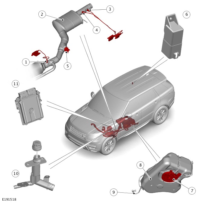
| ITEM | DESCRIPTION |
|---|---|
| 1 | Pre Selective Catalyst Reduction (SCR) NOx sensor - North American Specification (NAS) market vehicles only |
| 2 | Selective Catalyst Reduction (SCR) catalytic converter |
| 3 | Post Selective Catalyst Reduction (SCR) NOx sensor |
| 4 | Post Selective Catalyst Reduction (SCR) soot sensor - North American Specification (NAS) market vehicles only |
| 5 | Diesel Exhaust Fluid (DEF) injector |
| 6 | Diesel Exhaust Fluid (DEF) heater control unit |
| 7 | Diesel Exhaust Fluid (DEF) tank module |
| 8 | Diesel Exhaust Fluid (DEF) tank |
| 9 | Diesel Exhaust Fluid (DEF) line |
| 10 | Diesel Exhaust Fluid (DEF) filler neck |
| 11 | Powertrain Control Module (PCM) |
The Selective Catalyst Reduction (SCR) system is an exhaust gas aftertreatment solution used to reduce the Nitrogen Oxide (NOx) within the exhaust gas.
For this purpose, a specified amount of Diesel Exhaust Fluid (DEF) is injected into the exhaust system, downstream of the Diesel Particulate Filter (DPF). The injected DEF into the exhaust system is converted to ammonia (NH3) and carbon dioxide (CO2). The resulting ammonia (NH3) is used within a special catalyst in the exhaust stream. The resulting reaction converts the unwanted NOx into harmless nitrogen (N2) and water (H2O) vapor.
DIESEL EXHAUST FLUID
Diesel Exhaust Fluid (DEF) is a pure, odorless, colorless, synthetically manufactured, 32.5% aqueous solution of urea. DEF is used for the aftertreatment of exhaust gases in a Selective Catalyst Reduction (SCR) catalytic converter.
The SCR catalytic converter can be contaminated by low quantities of metals and thus the quality of the DEF fluid is held to closely controlled standards. DEF cannot be substituted by urea used in agriculture or diluted with any other fluid.
DEF is not categorized as a dangerous substance, it is non-flammable and non-toxic, there is no danger in the event of spills. DEF can be stored on board vehicles, despite the limitation that it crystallizes at temperatures below -11°C (12°F).
In Europe, DEF is also known as AdBlue®, the fluid is specified by ISO22241.
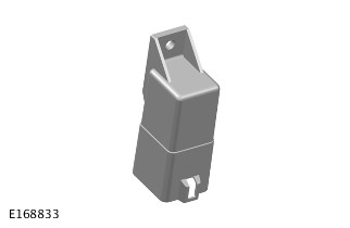
DIESEL EXHAUST FLUID TANK
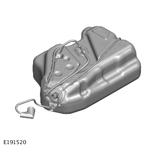
The Diesel Exhaust Fluid (DEF) tank is blow moulded from high-density polyethylene and is located at the front left side of the fuel tank. The DEF tank is mounted in a shield bolted to the underside of the vehicle floor pan and an additional shield covers the DEF tank module. The DEF tank contains the DEF tank module which is welded into the tank and supplied as a unit. The tank includes a 12% unusable volume to protect the internal components as a result of fluid expansion under freezing conditions.
If the ambient temperature falls below -11°C (12°F), the DEF will freeze in the DEF tank, this will provide difficulty with the refill procedure. In order to thaw the DEF in the DEF tank, place the vehicle in a warm place for up to 2 hours before attempting to refill the tank.
The volume of the DEF tank is different on all Jaguar and Land Rover products. The DEF tank has been designed so that refills are minimized outside of the vehicle service intervals.
During extended usage in extreme temperatures, ’at altitude’ or aggressive drive cycles the vehicle may consume more DEF than anticipated. In this case a warning message will be displayed in the Instrument Cluster (IC) message center to add DEF to the tank.
DIESEL EXHAUST FLUID TANK MODULE
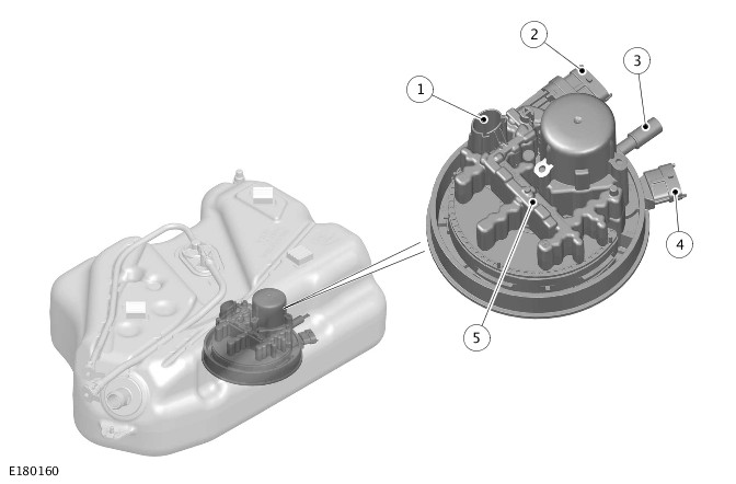
| ITEM | DESCRIPTION |
|---|---|
| 1 | Diesel Exhaust Fluid (DEF) level sensor |
| 2 | Diesel Exhaust Fluid (DEF) tank module electrical connection |
| 3 | Diesel Exhaust Fluid (DEF) line connection |
| 4 | Diesel Exhaust Fluid (DEF) injection pump electrical connection |
| 5 | Diesel Exhaust Fluid (DEF) heater element |
The Diesel Exhaust Fluid (DEF) tank module is located at the bottom of the DEF tank. The module is welded into the tank and can only be replaced as a complete assembly.
The DEF tank module comprises the following components:
- Life-time fit filter
- Fluid level sensor
- Temperature sensor
- Heater element.
The fluid level sensor is an ultrasonic device which sends the fluid level value to the Powertrain Control Module (PCM) via Pulse Width Modulation (PWM) signals. The ultrasonic cone angle is 10° and the readings are most accurate when the vehicle is stationary and on level ground.
The heater element is used to defrost the DEF in extreme cold climates. The heater element is a Positive Temperature Coefficient (PTC) type heater, which provides safe operation to the system. Increased heater element temperature results in decreased current drawn from the DEF heater control unit, which actuates the power supply of the heater element. Under normal operation the maximum current is 6 A.
DIESEL EXHAUST FLUID INJECTION PUMP
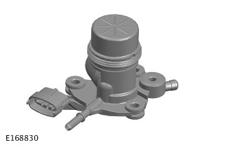
The Diesel Exhaust Fluid (DEF) injection pump is an assembly of two solenoid pumps, located in the DEF tank module.
The pressure pump provides 6.5 bar (94.27 lbf/in²) operating pressure. The 6.5 bar (94.27 lbf/in²) pressure is required to maintain the complete DEF atomization in the exhaust gas.
The purge pump is used to purge the DEF from the DEF line at engine shut-down to prevent freezing in the DEF injector at low temperatures.
The pumps receive a permanent power supply from the Battery Junction Box (BJB) and a Powertrain Control Module (PCM) controlled ignition signal from the Rear Junction Box (RJB). The PCM controls the ground connection of the pumps individually via hardwired connections.
DIESEL EXHAUST FLUID LINE
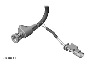
The Diesel Exhaust Fluid (DEF) line provides connection between the DEF injection pump and the DEF injector. The DEF line is manufactured from a plastic material which is specifically designed for use with DEF.
A copper nickel alloy resistor wire is installed within the DEF line with an electrical connector. The resistor wire enables electrical heating of the DEF at low-ambient temperatures.
The DEF line has hardwired connections to the DEF heater control unit, which actuates the power supply for the heater element. The DEF heater control unit is controlled by the Powertrain Control Module (PCM) via the private Controller Area Network (CAN) bus.
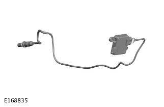
DIESEL EXHAUST FLUID INJECTOR

The Diesel Exhaust Fluid (DEF) injector is located in the exhaust system downstream of the Diesel Particulate Filter (DPF). The DEF injector is secured to the S-shaped exhaust pipe with a clamp. Due to the position of the injector, the DEF is injected axially to the exhaust gas flow direction. The DEF is then mixed well and distributed evenly within the exhaust gas. The DEF injector consists of an injector and a passive cooling heat sink, this protects the injector from overheating due to the high exhaust temperatures.
The DEF injector works at high pressures to obtain the complete atomization of the injected DEF. This provides the Selective Catalyst Reduction (SCR) catalytic converter is working to its optimum performance. The DEF injector is controlled by the Powertrain Control Module (PCM) with Pulse Width Modulation (PWM) signals.
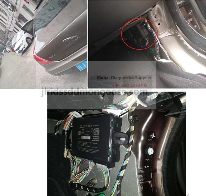
DIESEL EXHAUST FLUID HEATER CONTROL UNIT
The Diesel Exhaust Fluid (DEF) heater control unit is located on the right side of the luggage compartment, behind the side trim panel. The heater system provides an adequate quantity of defrosted DEF that is available at all operating points. As a result, this enables rapid Selective Catalyst Reduction (SCR) system operation in the event of frozen DEF. The DEF heater control unit has a switched power supply from the Rear Junction Box (RJB), which is controlled by the Powertrain Control Module (PCM).
The DEF heater control unit has hardwired connections to the DEF tank module and the DEF line heater element. If the ambient air temperature is below -5°C (23°F), the PCM switches on the DEF heater control unit via the private Controller Area Network (CAN) bus. The DEF heater control unit energizes the heater elements, located in the DEF tank module and in the DEF line. The DEF heater control unit has on-board diagnostics to detect and report faults to the PCM via the private CAN bus.
SELECTIVE CATALYST REDUCTION NOX SENSOR
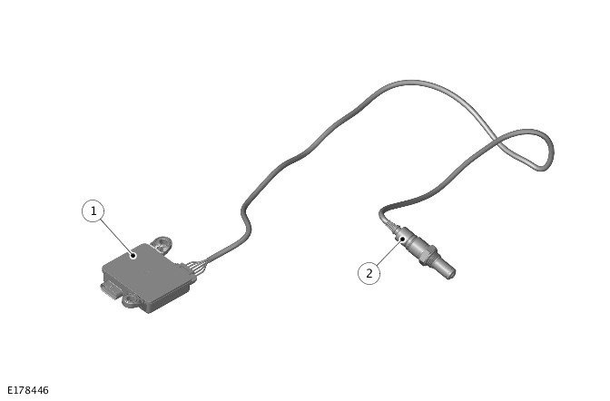
| ITEM | DESCRIPTION |
|---|---|
| 1 | Selective Catalyst Reduction (SCR) NOx sensor module |
| 2 | Selective Catalyst Reduction (SCR) NOx sensor |
The Selective Catalyst Reduction (SCR) NOx sensor is located in the exhaust pipe downstream of the SCR catalytic converter. On North American Specification (NAS) market vehicles there is an additional NOx sensor fitted upstream of the SCR catalytic converter. The NOx sensor comprises a sensor element attached to a dedicated control module with a hardwired connection.
The sensor and the control module are replaced as an assembly. The NOx sensor is an evolution of the wide band oxygen sensor. The sensor element is constructed from special ceramics and contains two oxygen density detecting chambers that work together to determine the NOx concentration in the exhaust gas. The control module sends a message via the private Controller Area Network (CAN) bus to the Powertrain Control Module (PCM) for monitoring the effectiveness of the SCR system.
POST SELECTIVE CATALYST REDUCTION SOOT SENSOR - NORTH AMERICAN SPECIFICATION MARKET VEHICLES ONLY
The post Selective Catalyst Reduction (SCR) soot sensor is located in the exhaust pipe downstream of the SCR catalytic converter. The sensor measures the soot particles in the exhaust gas to evaluate the Diesel Particulate Filter (DPF) functionality.
The soot sensor comprises a sensor element attached to a dedicated control module with hardwired connection. The sensor and the control module can be replaced as an assembly. The absorbed soot particles form conductive paths between the electrode combs in the sensor element. The control module measures the resistance between the electrode combs. To evaluate the DPF functionality it sends a message to the Powertrain Control Module (PCM) via a private Controller Area Network (CAN) bus.
The control module regularly overheats the electrode combs to regenerate the sensor element.
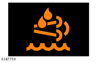
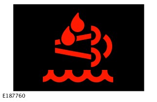
WARNING MESSAGES
It is a legal requirement for the driver to be informed of Selective Catalyst Reduction (SCR) system faults. If the performance of the SCR system is reduced a warning indicator symbol will illuminate and a message will be displayed in the Instrument Cluster (IC) message center.
Dependent on the warning stage, the reagent warning indicator symbol will be amber or red.
There are three possible routes to receive a fault message on the Instrument Cluster (IC):
- Low Diesel Exhaust Fluid (DEF) volume in the DEF tank.
- Incorrect DEF quality supplied to the Selective Catalyst Reduction (SCR) system.
- Efficiency of the SCR system is reduced in the event of a system fault.
There are five warning stages displayed in the Instrument Cluster (IC) message center. Each warning progresses, until a final 'No Engine Restart Possible' warning is displayed.
If the Diesel Exhaust Fluid (DEF) fluid is not replenished within this distance, and the engine is turned off, the vehicle will fail to start. In this event Customers can use two standard size refill bottles as a short term solution to restart the vehicle. A complete refill of the DEF tank will still be required by an authorized Land Rover retailer.
| STAGE | WARNING | MESSAGE | CAUSE |
|---|---|---|---|
| Stage 1 | Message at engine start | Diesel Exhaust Fluid Level Low | DEF range <2400 km/1500 miles |
| Stage 2 | Amber symbol | Fill Diesel Exhaust Fluid Tank | DEF range <1610 km/1000 miles |
| Stage 3 | Amber symbol | No Engine Restarts Possible in 800 km/ 500 miles. Fill Diesel Exhaust Fluid Tank | DEF range <800 km/500 miles |
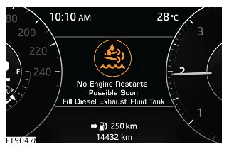
| Stage 4 | Amber symbol | No Engine Restarts Possible Soon. Fill Diesel Exhaust Fluid Tank | DEF range <160 km/100 miles |
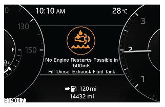
| Stage 5 | Red symbol | No Engine Restarts Possible. Fill Diesel Exhaust Fluid Tank | DEF range 0 km/0 miles |
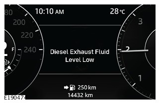
Stage 1 is a low priority message, 'Diesel Exhaust Fluid Level Low' is displayed on the message center. Then 2400 km (1500 miles) is given without any vehicle restriction in order to allow time to visit an authorized Land Rover retailer to refill the DEF tank.
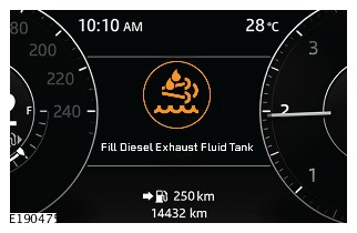
Stage 2 is an amber warning symbol with the message 'Fill Diesel Exhaust Fluid Tank', but no distance reference is given at this stage.

Stage 3 is an amber warning symbol with a distance reference before the DEF tank is empty.
Stage 4 is the final amber warning symbol, no distance reference is given, but approximately 160 km (100 miles) remain before the DEF tank is empty.
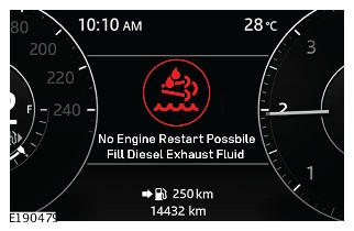
Stage 5 is a red warning symbol, this indicates the DEF tank is empty and restart of the vehicle is no longer possible. In this event Customers can use two standard size refill bottles as a short term solution to restart the vehicle. A complete refill of the DEF tank will still be required by an authorized Land Rover retailer.
The system must be able to identify and respond when the fluid in the Diesel Exhaust Fluid (DEF) tank is not to specification.
The Selective Catalyst Reduction (SCR) system infers the quality of the DEF through investigation of the SCR NOx reduction efficiency. The function is processed using the NOx sensor and Powertrain Control Module (PCM) mapping strategy to continuously determine the calculated SCR conversion efficiency.
If incorrect DEF quality is detected, a corrective action needs to be taken to drain and refill the DEF tank with the correct DEF.
There are four warning stages displayed in the Instrument Cluster (IC) message center, until corrective action is carried out. Each warning progresses, until a final 'No Engine Restarts Possible. Incorrect Diesel Exhaust Fluid Quality Detected' warning is displayed.
| STAGE | WARNING | MESSAGE | CAUSE |
|---|---|---|---|
| Stage 1 | Amber symbol | Incorrect Diesel Exhaust Fluid Quality Detected | |
| Stage 2 | Amber symbol | No Engine Restarts Possible in 400 km/250 miles. Incorrect Diesel Exhaust Fluid Quality Detected | DEF range <400 km/250 miles |
| Stage 3 | Amber symbol | No Engine Restarts Possible Soon. Incorrect Diesel Exhaust Fluid Quality Detected | DEF range <160 km/100 miles |
| Stage 4 | Red symbol | No Engine Restarts Possible. Incorrect Diesel Exhaust Fluid Quality Detected | DEF range 0 km/0 miles |
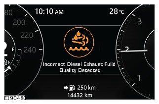
Stage 1 is an amber warning symbol indicating the 'Incorrect Diesel Exhaust Fluid Quality Detected' message.
At this stage no distance reference is given. This advises, that a corrective action is required to drain and refill the DEF tank with the correct quality DEF by an authorized Land Rover retailer.
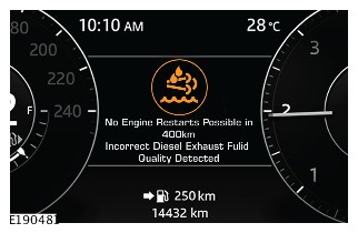
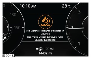
Stage 2 is an amber warning symbol with a distance reference to advise corrective action. To drain and refill the DEF tank with the correct DEF fluid needs to be taken within the distance range stated.
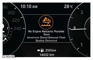
Stage 3 is the final amber warning symbol, no distance reference is given. Approximately 160 km (100 miles) remain for a corrective action to drain and refill the DEF tank with the correct DEF fluid. Otherwise engine restart will not be possible.

Stage 4 is a red warning symbol, this indicates the available distance for a corrective action has expired. The engine restart is inhibited until a drain and refill of the DEF tank with the correct DEF fluid is undertaken by an authorized Land Rover retailer.
Legislation requires that Diesel Exhaust Fluid (DEF) is continuously available to the Selective Catalyst Reduction (SCR) system. An Instrument Cluster (IC) message center warning is displayed if a fault is detected which prevents correct system operation.
There are two warning stages displayed in the IC message center, until corrective action is carried out.
| STAGE | WARNING | MESSAGE | CAUSE |
|---|---|---|---|
| Stage 1 | Amber symbol | No Engine Restarts Possible in 400 km/250 miles | DEF range <400 km/250 miles |
| Stage 2 | Red symbol | No Engine Restarts Possible | DEF range 0 km/0 miles |
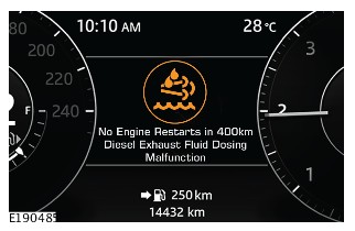
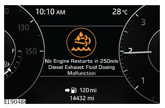
Stage 1 is an amber warning symbol with a distance reference. Fault diagnosis must be undertaken by an authorized Land Rover retailer within the distance range stated.
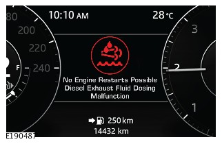
Stage 2 is a red warning symbol, this indicates the available distance for a corrective action has expired. The engine restart is inhibited and fault diagnosis is required to be undertaken by an authorized Land Rover retailer.
SELECTIVE CATALYST REDUCTION SYSTEM SCHEMATIC DIAGRAM
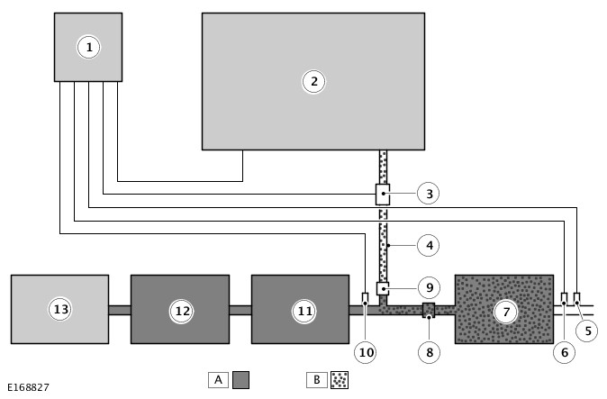
A = EXHAUST GAS; B = DIESEL EXHAUST FLUID (DEF).
| ITEM | DESCRIPTION |
|---|---|
| 1 | Powertrain Control Module (PCM) |
| 2 | Diesel Exhaust Fluid (DEF) tank with Diesel Exhaust Fluid (DEF) tank module |
| 3 | Diesel Exhaust Fluid (DEF) injection pump |
| 4 | Diesel Exhaust Fluid (DEF) line |
| 5 | Post Selective Catalyst Reduction (SCR) NOx sensor |
| 6 | Post Selective Catalyst Reduction (SCR) soot sensor (North American Specification (NAS) market vehicles only) |
| 7 | Selective Catalyst Reduction (SCR) catalytic converter |
| 8 | Mixer plate |
| 9 | Diesel Exhaust Fluid (DEF) injector |
| 10 | Pre Selective Catalyst Reduction (SCR) NOx sensor (North American Specification (NAS) market vehicles only) |
| 11 | Diesel Particulate Filter (DPF) |
| 12 | Catalytic converter |
| 13 | Engine |
The Selective Catalyst Reduction (SCR) catalytic converter reaches the operating temperature at 150°C (302°F). The temperature of the exhaust gas is measured by the post Diesel Particulate Filter (DPF) exhaust gas temperature sensor. The sensor is connected to the Powertrain Control Module (PCM).
The Diesel Exhaust Fluid (DEF) injection pump supplies the DEF from the DEF tank at a pressure of 6.5 bar (94.27 lbf/in²) to the DEF injector via the heated DEF line. The DEF injector is controlled with a Pulse Width Modulation (PWM) signal by the PCM.
The injected DEF is carried along by the exhaust gas flow and is evenly distributed in the exhaust gas by the mixer plate. The mixer plate is located in the exhaust pipe upstream of the SCR catalytic converter and downstream of the DEF injector. After the injection, the DEF is converted into ammonia (NH3) and carbon dioxide (CO2) during chemical reactions.
In the SCR catalytic converter, the ammonia (NH3) reacts with the Nitrogen Oxide (NOx) to produce nitrogen (N2) and water (H2O) vapor. The SCR system's efficiency is registered by the post SCR NOx sensor.
In order to optimize the SCR system's efficiency, the correct amount of ammonia (NH3) is required in the exhaust gas. The ammonia (NH3) is stored on the catalytic converter and used as a function of the NOx feed.
The objective of the control system is to provide that the pre-determined amount of NH3 is available on the SCR catalytic converter at any given time.

A = HARDWIRED; AL = PULSE WIDTH MODULATION (PWM); U = PRIVATE CONTROLLER AREA NETWORK (CAN) BUS.
| ITEM | DESCRIPTION |
|---|---|
| 1 | Powertrain Control Module (PCM) |
| 2 | Diesel Exhaust Fluid (DEF) heater control unit |
| 3 | Diesel Exhaust Fluid (DEF) tank module |
| 4 | Diesel Exhaust Fluid (DEF) line |
| 5 | Diesel Exhaust Fluid (DEF) injector |
| 6 | Diesel Exhaust Fluid (DEF) injection pump |
| 7 | Ground |
| 8 | Power supply |
| 9 | Diesel Exhaust Fluid (DEF) tank module |
| 10 | Post Selective Catalyst Reduction (SCR) NOx sensor |
| 11 | Post Selective Catalyst Reduction (SCR) soot sensor - North American Specification (NAS) market vehicles only |
| 12 | Pre Selective Catalyst Reduction (SCR) NOx sensor - North American Specification (NAS) market vehicles only |
EXHAUST SYSTEM - TDV6 3.0L DIESEL - GEN 2 (G1549763)
For a detailed description of the exhaust system, refer to the relevant Description and Operation section of the workshop manual. REFER to:Exhaust System (309-00A Exhaust System - TDV6 3.0L Diesel - Gen 2, Description and Operation).
Diagnosis by substitution from a donor vehicle is NOT acceptable. Substitution of control modules does not guarantee confirmation of a fault and may also cause additional faults in the vehicle being checked and/or the donor vehicle
Check and rectify basic faults before beginning diagnostic routines involving pinpoint tests
- Verify the customer concern
- Visually inspect for obvious signs of mechanical or electrical damage
Visual Inspection
| MECHANICAL | ELECTRICAL |
|---|---|
|
|
- If an obvious cause for an observed or reported concern is found, correct the cause (if possible) before proceeding to the next step
- If the cause is not visually evident, verify the symptom and refer to the Symptom Chart, alternatively check for Diagnostic Trouble Codes and refer to the Diagnostic Trouble Code(s) (DTC) Index
| SYMPTOM | POSSIBLE CAUSES | ACTION |
|---|---|---|
| Noisy or leaking exhaust |
|
|
| Smell of exhaust fumes entering the passenger compartment and/or noticeable from under the hood |
|
|
| Lack of power |
|
|
16 Model Year (MY) onwards vehicles
A customer may describe a smell of exhaust fumes from the front of the vehicle noticeable in the passenger compartment, and/or a smell of exhaust fumes from under the hood. There may also be an abnormal exhaust sound under certain operating conditions.
Inspect the front hot end of the exhaust system and joints for leaks.
Referring to the image below identify which joint is the source of the leak.
Check and complete the steps below:
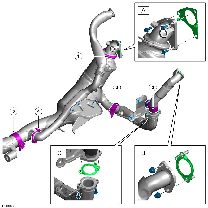
- Check all fixings are present and correct according to the image. The components are highlighted in blue
- Check all gaskets are present and correct according to the image. The components are highlighted in green
- Check all clamps are present and in the correct position according to the image. The components are highlighted in purple
- Undo each of the clamps in number order and torque back to the specified value. REFER to: Exhaust System - Vehicles Without: Diesel Particulate Filter (309-00, Removal and Installation) / Exhaust System - Vehicles With: Diesel Particulate Filter (309-00, Removal and Installation)
- Check the pollen filter for signs of contamination. REFER to: Pollen Filter (412-01, Removal and Installation)
- If any clamps and gaskets are damaged or missing, install new components as necessary. REFER to: Exhaust System - Vehicles Without: Diesel Particulate Filter (309-00, Removal and Installation) / Exhaust System - Vehicles With: Diesel Particulate Filter (309-00, Removal and Installation)
- If the pollen filter is contaminated, install a new pollen filter as necessary. REFER to: Pollen Filter (412-01, Removal and Installation)
- Please submit an Electronic Product Quality Report (EPQR) with the torque figure required to tighten each bolt along with a reference from the image above identifying the leaking joint(s)
For a complete list of all diagnostic trouble codes that could be set on this vehicle, please refer to Section 100-00. REFER to:Diagnostic Trouble Code Index - TDV6 3.0L Diesel /TDV6 3.0L Diesel - Gen 1.5/TDV6 3.0L Diesel - Gen 2, DTC: Powertrain Control Module B10A2-07 to P02D7-32 (100-00 General Information, Description and Operation).
EXHAUST SYSTEM - TDV6 3.0L DIESEL - GEN 2
DIESEL PARTICULATE FILTER - TDV6 3.0L DIESEL - GEN 2 (G1900162)
For a detailed description of the exhaust system, refer to the relevant description and operation section of the workshop manual. REFER to:
- Verify the customer concern.
- Visually inspect for obvious signs of mechanical or electrical damage.
Visual Inspection
| MECHANICAL | ELECTRICAL |
|---|---|
|
|
- If an obvious cause for an observed or reported concern is found, correct the cause (if possible) before proceeding to the next step
- If the cause is not visually evident, verify the symptom and refer to the symptom chart.
For a list of Diagnostic Trouble Codes (DTCs) that could be logged on this vehicle, please refer to Section 100-00
-
If the control module or a component is suspect and the vehicle remains under manufacturer warranty, refer to the Warranty Policy and Procedures manual (section B1.2), or determine if any prior approval programme is in operation, prior to the installation of a new module/component
-
Generic scan tools may not read the codes listed, or may read only 5-digit codes. Match the 5 digits from the scan tool to the first 5 digits of the 7-digit code listed to identify the fault (the last 2 digits give extra information read by the manufacturer approved diagnostic system)
-
Check and rectify basic faults before beginning diagnostic routines involving pinpoint tests
-
Inspect connectors for signs of water ingress, and pins for damage and/or corrosion
-
If DTCs are recorded and, after performing the pinpoint tests, a fault is not present, an intermittent concern may be the cause. Always check for loose connections and corroded terminals
| DTC | DESCRIPTION | POSSIBLE CAUSE | ACTION |
|---|---|---|---|
| P0030-29 | HO2S Heater Control Circuit Bank 1 Sensor 1 - Signal invalid |
|
|
| P0031-11 | HO2S Heater Control Circuit Low Bank 1 Sensor 1 - Circuit short to ground |
|
|
| P0032-12 | HO2S Heater Control Circuit High Bank 1 Sensor 1 - Circuit short to battery |
|
|
| P0131-11 | O2 Sensor Circuit Low Voltage Bank 1 Sensor 1 - Circuit short to ground |
|
|
| P0132-12 | O2 Sensor Circuit High Voltage Bank 1 Sensor 1 - Circuit short to battery |
|
|
| P0134-00 | O2 Sensor Circuit No Activity Detected Bank 1 Sensor 1 - No sub type information |
|
|
| P0135-29 | O2 Sensor Heater Circuit Bank 1 Sensor 1 - Signal invalid |
|
|
| P014C-00 | O2 Sensor Slow Response - Rich to Lean Bank 1 Sensor 1 - No sub type information |
|
|
| P014D-00 | O2 Sensor Slow Response - Lean to Rich Bank 1 Sensor 1 - No sub type information |
|
|
| P0171-00 | System Too Lean Bank 1 - No sub type information |
|
|
| P0172-00 | System Too Rich Bank 1 - No sub type information |
|
|
| P0234-77 | Turbocharger/Supercharger "A" Overboost Condition - Commanded position not reachable |
NOTE:
A customer may express a concern that the amber Diesel Particulate Filter (DPF) warning indicator is illuminated on the Instrument Cluster (IC) requesting a DPF regeneration. If the regeneration is not completed the DPF warning indicator will then turn red. The DTCs P2463-00 and P246B-00 will be stored in the Powertrain Control Module (PCM) memory
|
|
| P0420-00 | Catalyst System Efficiency Below Threshold Bank 1 - No Sub Type Information |
NOTE:
Diesel oxidation catalyst exothermic generation capability check. Diesel oxidation catalyst monitoring runs during the active regeneration of the particulate filter. The exhaust gas temperature measured at the catalyst outlet is compared against a model of the expected temperature increase during the active regeneration. A malfunction is reported when the measured temperature is significantly different to this model. The monitoring returns a judgment around 10min after the active particulate filter regeneration was started
|
|
| P0544-22 | Exhaust Gas Temperature Sensor Circuit Bank 1 Sensor 1 - Signal amplitude > maximum |
NOTE:
To monitor for too high temperature in the turbine housing; component protection. Temperature sensor temperature above threshold (899.96°C)
|
|
| P0545-16 | Exhaust Gas Temperature Sensor Circuit Low Bank 1 Sensor 1 - Circuit voltage below threshold |
|
|
| P0546-17 | Exhaust Gas Temperature Sensor Circuit High Bank 1 Sensor 1 - Circuit voltage above threshold |
|
|
| P064D-00 | Internal Control Module O2 Sensor Processor Performance Bank 1 - No sub type information |
NOTE:
SPI communication within heated oxygen sensor internal chip has been disrupted
|
|
| P2002-00 | Diesel Particulate Filter Efficiency Below Threshold (Bank 1) - No sub type information |
|
|
| P2031-22 | Exhaust Gas Temperature Sensor Circuit Bank 1 Sensor 2 - Signal amplitude > maximum |
NOTE:
To monitor for too high temperature at the diesel oxidation catalyst outlet location; DOC/DPF component protection. Temperature sensor temperature above threshold (874.96°C)
|
|
| P2032-16 | Exhaust Gas Temperature Sensor Circuit Low Bank 1 Sensor 2 - Circuit voltage below threshold |
NOTE:
Exhaust gas temperature sensor voltage below threshold (80mV)
|
|
| P2033-17 | Exhaust Gas Temperature Sensor Circuit High Bank 1 Sensor 2 - Circuit voltage above threshold |
NOTE:
Exhaust gas temperature sensor voltage above threshold (4990mV)
|
|
| P2080-62 | Exhaust Gas Temperature Sensor Circuit Range/Performance Bank 1 Sensor 1 - Signal compare failure |
NOTE:
Exhaust gas temperature sensor - Turbine temperature sensor rationality check. Temperature sensor is checked against other temperature sensors at coldstart
|
|
| P2080-64 | Exhaust Gas Temperature Sensor Circuit Range/Performance Bank 1 Sensor 1 - Signal plausibility failure |
NOTE:
Exhaust gas temperature sensor - Turbine temperature sensor rationality check during a driving cycle is not plausible (compared against a temperature model). Exhaust temperature sensor temperature is checked during a vehicle driving cycle against a model temperature for rationality. Some engine speed/load conditions apply. If the difference between the sensor temperature and the model exceeds a defined threshold, a malfunction is raised
|
|
| P2084-62 | Exhaust Gas Temperature Sensor Circuit Range/Performance Bank 1 Sensor 2 - Signal compare failure |
NOTE:
Exhaust gas temperature sensor temperature at least 50°C above other exhaust gas temperature sensors temperature after 90 minutes engine off time
|
|
| P2084-64 | Exhaust Gas Temperature Sensor Circuit Range/Performance Bank 1 Sensor 2 - Signal plausibility failure |
NOTE:
Exhaust gas temperature sensor temperature is checked during a vehicle driving cycle against a model temperature for rationality. Some engine speed/load conditions apply. If the difference between the sensor temperature and the model exceeds a defined threshold, the DTC is set
|
|
| P20EE-00 | SCR NOx Catalyst Efficiency Below Threshold (Bank 1) - No sub type information |
NOTE:
Monitors SCR Nox catalyst efficiency - Reduced catalyst Nox efficiency
|
NOTE:
Drive vehicle at urban speeds until SCR catalyst warm and exhaust Nox sensors active. Ensure the vehicle is not in DPF active regeneration and drive at urban speeds for 20min (50 / 60mph)
|
| P2195-00 | O2 Sensor Signal Biased/Stuck Lean - Bank 1, Sensor 1 - No sub type information |
NOTE:
Measured oxygen concentration implausibly high compared to model oxygen concentration for Sensor 1 Bank 1, during part load and during low part load
|
|
| P2195-85 | O2 Sensor Signal Biased/Stuck Lean - Bank 1, Sensor 1 - Signal above allowable range |
|
|
| P2196-00 | O2 Sensor Signal Biased/Stuck Rich - Bank 1, Sensor 1 - No sub type information |
NOTE:
Measured oxygen concentration implausibly low compared to model oxygen concentration for Sensor 1 Bank 1, during part load and during low part load
|
|
| P2196-84 | O2 Sensor Signal Biased/Stuck Rich - Bank 1, Sensor 1 - Signal below allowable range |
|
|
| P223C-00 | O2 Sensor Pumping Current Range/Performance Bank 1 - No sub type information |
|
|
| P2251-13 | O2 Sensor Negative Current Control Circuit / Open - Bank 1, Sensor 1 - Circuit open |
|
|
| P226D-00 | Particulate Filter Deteriorated/Missing Substrate Bank 1 - No sub type information |
|
NOTE:
Operational requirements needed to allow the monitor to be fully tested. Drive at steady 70mph 6th gear for 10 minutes. Return to workshop and turn engine off, wait 5 minutes, key on and check for DTC
|
| P2414-00 | O2 Sensor Exhaust Sample Error Bank 1, Sensor 1 - No sub type information |
NOTE:
Measured oxygen concentration implausible compared to other Nox Sensor, bank 1, during part load
|
|
| P242A-22 | Exhaust Gas Temperature Sensor Circuit Bank 1 Sensor 3 - Signal amplitude > maximum |
NOTE:
To monitor for too high temperature at the diesel oxidation catalyst outlet location; DOC/DPF component protection. Temperature sensor temperature above threshold (874.96°C)
|
|
| P242B-62 | Exhaust Gas Temperature Sensor Circuit Range/Performance Bank 1 Sensor 3 - Signal compare failure |
NOTE:
Exhaust gas temperature sensor - Post catalytic converter sensor rationality check. Temperature sensor is checked against other temperature sensors at coldstart
|
|
| P242B-64 | Exhaust Gas Temperature Sensor Circuit Range/Performance Bank 1 Sensor 3 - Signal plausibility failure |
NOTE:
Exhaust gas temperature sensor - Post catalytic converter sensor rationality check during a driving cycle is not plausible (compared against a temperature model). Exhaust temperature sensor temperature is checked during a vehicle driving cycle against a model temperature for rationality. Some engine speed/load conditions apply. If the difference between the sensor temperature and the model exceeds a defined threshold, a malfunction is raised
|
|
| P242C-16 | Exhaust Gas Temperature Sensor Circuit Low Bank 1 Sensor 3 - Circuit voltage below threshold |
|
|
| P242D-17 | Exhaust Gas Temperature Sensor Circuit High Bank 1 Sensor 3 - Circuit voltage above threshold |
|
|
| P244A-00 | Diesel Particulate Filter Differential Pressure Too Low (Bank 1) - No sub type information |
|
NOTE:
If this DTC is logged, refer to the relevant pinpoint tests in Section 309-00 (Exhaust System)
|
| P244A-95 | Diesel Particulate Filter Differential Pressure Too Low (Bank1) - Incorrect assembly |
NOTE:
Differential pressure sensor hoseline mounting check. Differential pressure sensor high pressure hoseline disconnected or differential pressure reading low
|
NOTE:
If this DTC is logged, refer to the relevant pinpoint tests in Section 309-00 (Exhaust System)
|
| P244A-96 | Diesel Particulate Filter Differential Pressure Too Low (Bank 1) - Component internal failure |
|
NOTE:
If this DTC is logged, refer to the relevant pinpoint tests in Section 309-00 (Exhaust System)
|
| P2453-28 | Diesel Particulate Filter Pressure Sensor A Circuit Range/Performance - Signal bias level out of range / zero adjustment failure |
NOTE:
Differential pressure sensor rationality check in afterrun. Differential pressure plausibility check during postdrive in every driving cycle. If the pressure exceeds a defined threshold, (set at 55hPa), the sensor is no longer within specification range
|
|
| P2453-2A | Diesel Particulate Filter Pressure Sensor A Circuit Range/Performance - Signal stuck in range |
NOTE:
Differential pressure sensor rationality check during exhaust gas flow dynamic conditions. Differential pressure sensor pressure response responds to exhaust gas flow transients
|
|
| P2454-16 | Diesel Particulate Filter Pressure Sensor A Circuit Low - Circuit voltage below threshold |
NOTE:
Differential pressure sensor circuit continuity check. Differential pressure sensor voltage below threshold (80mV)
|
|
| P2454-21 | Diesel Particulate Filter Pressure Sensor A Circuit Low - Signal amplitude < minimum |
|
|
| P2455-17 | Diesel Particulate Filter Pressure Sensor A Circuit High - Circuit voltage above threshold |
NOTE:
Differential pressure sensor circuit continuity check. Differential pressure sensor voltage above threshold (4990mV)
|
|
| P2455-22 | Diesel Particulate Filter Pressure Sensor A Circuit High - Signal amplitude > maximum |
|
|
| P2459-00 | Diesel Particulate Filter Regeneration Frequency (Bank 1) - No sub type information |
NOTE:
Unexpected rapid soot loading of the diesel particulate filter leading to an increased regeneration frequency. Diesel particulate filter soot mass is compared to a maximum soot mass expected during soot loading phases when the diesel particulate filter active regeneration is started. A soot mass higher that the maximum expected soot loading leads to an increased regeneration frequency
|
|
| P2463-00 | Diesel Particulate Filter Restriction - Soot Accumulation (Bank 1) - No sub type information |
NOTES:
|
|
| P246B-00 | Vehicle Conditions Incorrect for Diesel Particulate Filter Regeneration - No sub type information |
NOTES:
|
NOTE:
Operational requirements needed to allow the monitor to be fully tested. The diagnostic for this DTC runs all the time. Warning lamp and message will extinguish when the soot level is at an acceptable level
|
| P246E-22 | Exhaust Gas Temperature Sensor Circuit (Bank 1 Sensor 4) - Signal amplitude > maximum |
NOTE:
To monitor for too high temperature at the DPF outlet location. The DTC can indicate failure has occurred to the DPF during a previous regeneration. Temperature sensor temperature above threshold (874.96°C)
|
|
| P246F-62 | Exhaust Gas Temperature Sensor Circuit Range/Performance (Bank 1 Sensor 4) - Signal compare failure |
NOTE:
Exhaust gas temperature sensor - Post DPF sensor rationality check. Temperature sensor is checked against other temperature sensors at coldstart
|
|
| P246F-64 | Exhaust Gas Temperature Sensor Circuit Range/Performance (Bank 1 Sensor 4) - Signal plausibility failure |
NOTE:
Exhaust gas temperature sensor - Post DPF rationality check during a driving cycle is not plausible (compared against a temperature model). Exhaust temperature sensor temperature is checked during a vehicle driving cycle against a model temperature for rationality. Some engine speed/load conditions apply. If the difference between the sensor temperature and the model exceeds a defined threshold, a malfunction is raised
|
|
| P2470-16 | Exhaust Gas Temperature Sensor Circuit Low (Bank 1 Sensor 4) - Circuit voltage below threshold |
|
|
| P2471-17 | Exhaust Gas Temperature Sensor Circuit High (Bank 1 Sensor 4) - Circuit voltage above threshold |
|
|
| P2478-84 | Exhaust Gas Temperature Out of Range (Bank 1 Sensor 1) - Signal below allowable range |
|
|
| P2478-85 | Exhaust Gas Temperature Out of Range (Bank 1 Sensor 1) - Signal above allowable range |
|
|
| P2479-84 | Exhaust Gas Temperature Out of Range (Bank 1 Sensor 2) - Signal below allowable range |
NOTE:
Rationality check at start - Exhaust gas temperature sensor temperature under threshold (-40.04°C)
|
|
| P2479-85 | Exhaust Gas Temperature Out of Range (Bank 1 Sensor 2) - Signal above allowable range |
NOTE:
Rationality check at start - Exhaust gas temperature sensor temperature above threshold (879.96°C)
|
|
| P247A-84 | Exhaust Gas Temperature Out of Range Bank 1 Sensor 3 - Signal below allowable range |
|
|
| P247A-85 | Exhaust Gas Temperature Out of Range (Bank 1 Sensor 3) - Signal above allowable range |
|
|
| P247B-84 | Exhaust Gas Temperature Out of Range (Bank 1 Sensor 4) - Signal below allowable range |
|
|
| P247B-85 | Exhaust Gas Temperature Out of Range (Bank 1 Sensor 4) - Signal above allowable range |
|
|
| P249F-00 | Excessive Time To Enter Closed Loop DPF Regeneration Control - No sub type information |
NOTE:
Diesel particulate filter temperature of the inner loop (pre turbine) did not reach target on time. Diesel particulate filter temperature of the outer loop (post catalyst) did not reach target on time
|
|
| P24A0-00 | Closed Loop DPF Regeneration Control At Limit - Temperature Too Low - No sub type information |
NOTE:
Diesel particulate filter temperature of the inner loop (pre turbine) is under temperature target. Diesel particulate filter temperature of the outer loop (post catalyst) is under temperature target
|
|
| P24A1-00 | Closed Loop DPF Regeneration Control At Limit - Temperature Too High - No sub type information |
NOTE:
Diesel particulate filter temperature of the inner loop (pre turbine) is over temperature target. Diesel particulate filter temperature of the outer loop (post catalyst) is over temperature target
|
|
| P24A2-00 | Particulate Filter Regeneration Incomplete Bank 1 - No sub type information |
NOTE:
Diesel particulate filter soot mass is compared to a maximum soot mass expected at the end of an active diesel particulate filter active regeneration. A soot mass higher that the maximum expected soot mass after regeneration leads to an increased regeneration frequency
|
|
| P24A4-97 | Diesel Particulate Filter Restriction - Soot Accumulation Too High (Bank 1) - Component or system operation obstructed or blocked |
|
|
| P24C2-62 | Exhaust Gas Temperature Measurement System - Multiple Sensor Correlation Bank 1 - Signal compare failure |
NOTE:
Exhaust temperature sensor - Cross temperature sensor check failed at coldstart. More than one temperature sensor is not within a plausible range when comparing each other. Multiple temperature sensor temperature at least 50°C above other exhaust temperature sensors temperature after 90min engine off time
|
|
Pre catalyst oxygen sensor adaption cycle is NOT possible while DTCs are logged. Using the manufacturer approved diagnostic system, carry out FIT NEW PARTICULATE FILTER PROCESS only and clear the DTCs. After completing FIT NEW PARTICULATE FILTER PROCESS continue with pre catalyst oxygen sensor adaption cycle as follows:-1. Idle vehicle for 10 minutes 2. Set car in command shift 3rd gear 3. Accelerate to 3800RPM (where achievable) and overrun / coast down without braking until revs drop below 1500 RPM 4. Repeat step 3 a further 3 times 5. Check for any DTCs. If adaption has failed a DTC will be evident and the sensor will require replacement 6. Check oxygen sensor adaption is now complete. Using the manufacturer approved diagnostic system clear the DTC and re-test. Return vehicle to the customer
If a new diesel particulate filter pressure sensor or hose lines have been installed or incorrectly routed, or any pressure sensor circuit repairs carried out, the powertrain control module must learn and store the new diesel particulate filter pressure sensor offset value. The following conditions must be met to allow the diesel particulate filter pressure sensor offset value to be learnt and stored: Using the manufacturer approved diagnostic system, clear DTCs from powertrain control module, then monitor the datalogger signal 'sump oil temperature - measured' ensuring a minimum of 50 degrees C is achieved. Start engine, run above 500rpm for 2 minutes, then a further 30 seconds at idle. Ensure the engine cooling fan is not running. Set vehicle in park and set ignition status to off. Wait 30 seconds for the powertrain control module to power down, learn and store diesel particulate filter pressure sensor offset value. This process must be carried out six times, to allow a large negative offset value to adapt back to 0 Hpa
| SOOT LEVEL SYMPTOM | VALUES |
|---|---|
| Vehicle is still able to perform a drive cycle diesel particulate filter regeneration | 23 grams soot |
| Amber warning indicator is displayed - Customer can still perform a drive cycle diesel particulate filter regeneration | 27 grams soot |
| Red warning indicator is displayed - Visit the Dealer | 30.5 grams soot |
| Diesel particulate filter regeneration is NOT possible - Replace diesel particulate filter | 31.5 grams soot |
If DPF FULL SEE HANDBOOK appears in the message center, carry out the following procedure
-
The regeneration procedure produces high temperatures in the diesel particulate filter. Heat can be felt radiating from beneath the vehicle, which is normal and not a cause for concern. However, the vehicle should not be parked over combustible material, particularly during dry weather. The heat generated could be sufficient to start a fire when in close proximity to combustible material such as long dry grass, paper etc
-
At all times during this procedure you should observe all relevant speed limits, laws, and regulations
-
The ideal speed and conditions for regeneration are 100 km/h (62 mph ) ~ 120 km/h (75 mph), in Drive. Keeping a constant speed enables the diesel particulate filter to regenerate more efficiently. It is therefore recommended that cruise control is used to achieve this, if possible
-
When driving off-road during the regeneration process, greater accelerator pedal use may be required
- Drive the vehicle until the engine reaches normal operating temperature. The engine should NOT be left idling to achieve working temperature
- Drive the vehicle for a further twenty minutes, keeping the vehicle at a constant speed between 75 km/h (45 mph) and 120 km/h (75 mph)
- If regeneration is successful the warning message will be extinguished, once the message is extinguished please keep driving for 10 minutes to ensure that the diesel particulate filter is completely clean
- If the message remains repeat the process
For a list of DTCs that could be logged on this vehicle, please refer to Section 100-00. REFER to:Diagnostic Trouble Code Index - TDV6 3.0L Diesel /TDV6 3.0L Diesel - Gen 1.5/TDV6 3.0L Diesel - Gen 2, DTC: Powertrain Control Module B10A2-07 to P02D7-32 (100-00 General Information, Description and Operation).
EXHAUST SYSTEM - TDV6 3.0L DIESEL - GEN 2 (G1899143)
For a detailed description of the Exhaust System, refer to the relevant Description and Operation section of the workshop manual. REFER to:Selective Catalyst Reduction (309-00E Exhaust System - INGENIUM I4 2.0L Diesel, Description and Operation).
Diagnosis by substitution from a donor vehicle is NOT acceptable. Substitution of control modules does not guarantee confirmation of a fault, and may also cause additional faults in the vehicle being tested and/or the donor vehicle.
-
If a control module or a component is at fault and the vehicle remains under manufacturer warranty, refer to the Warranty Policy and Procedures manual, or determine if any prior approval program is in operation, prior to the installation of a new module/component.
-
When performing voltage or resistance tests, always use a digital multimeter that has the resolution ability to view 3 decimal places. For example, on the 2 volts range can measure 1mV or 2 K Ohm range can measure 1 Ohm. When testing resistance always take the resistance of the digital multimeter leads into account.
-
Check and rectify basic faults before beginning diagnostic routines involving pinpoint tests.
- Verify the customer concern
- Visually inspect for obvious signs of damage and system integrity
Visual Inspection
| MECHANICAL | ELECTRICAL |
|---|---|
|
|
- If an obvious cause for an observed or reported concern is found, correct the cause (if possible) before proceeding to the next step
- If the cause is not visually evident, verify the symptom and refer to the Symptom Chart, alternatively check for Diagnostic Trouble Codes (DTCs) and refer to the DTC Index
- Check JLR claims submission system for open campaigns. Refer to the corresponding bulletins and SSMs which may be valid for the specific customer complaint and complete the recommendations as required.
| SYMPTOM | POSSIBLE CAUSES | ACTION |
|---|---|---|
|
|
|
|
|
|
|
|
|
| CONTROL MODULE CAVITY | DESCRIPTION | DTC |
|---|---|---|
| Circuit reference I_T_RAULS Signal | PWM input to the powertrain control module |
|
| Circuit reference RAPM | PWM output from the powertrain control module |
|
| Circuit reference RAMV_L and Circuit reference RAMV_H | PWM output from the powertrain control module |
|
| Circuit reference CAN_3_H and Circuit reference CAN_L_3 | Diesel sub net CAN communication bus (High) |
|
| Circuit reference SCRMRLY | PWM output from the powertrain control module |
|
| Circuit reference RAPP | PWM output from the powertrain control module |
|
| ROUTINE DESCRIPTION | ROUTINE ACTION |
|---|---|
| Diesel exhaust fluid level check | To see current DEF level and then show the technician the required amount to top-up the tank if required |
| Reset selective catalyst reduction start inhibit | To Reset Selective Catalyst Reductant (SCR) Inducement System Start Inhibit |
| Reset selective catalyst reduction quality monitor | To Reset Selective Catalyst Reductant (SCR) Quality Monitor |
| SCR Dosing Module Test |
This cluster of routines tests:
|
| Diesel exhaust fluid injection pump replacement | To Reset DEF Pump Offset Calibration |
| Diesel exhaust fluid tank level sensor replacement | To Reset DEF Volume Using Sensed Tank Level |
| Diesel exhaust fluid prime and pressure test |
|
| PID | DESCRIPTION | ACTION |
|---|---|---|
| 0x043C | Reductant Tank Temperature - Raw |
|
| 0x0441 | Reductant Injector Duty Cycle |
|
| 0x05C1 | Reductant Tank Fluid Level |
|
| 0x05C2 | Reductant Tank Sensor Duty Cycles |
|
| 0x05CF | Reductant Purge Pump Duty Cycle - Commanded |
|
| 0x05D0 | Reductant Pump Duty Cycle - Commanded |
|
| 0x05D1 | Selective Catalyst Reductant Relay State - Commanded |
|
| 0x05FB | Learnt Heater Current Threshold For Heater Run Dry Detection - Frozen Cavity Detection In Diesel Exhaust Fluid Tank |
|
| 0x05FC | Total Mass Of Fluid Injected By Diesel Exhaust Fluid Dosing System |
|
| 0x05FD | Total Time Of Diesel Exhaust Fluid Dosing Valve Exceeding Upper Temperature Threshold |
|
| APPLICATION | APPLICATION |
|---|---|
| 16 MY Eu_A | 16 MY NAS_A |
The level of DEF in the tank is checked through the Instrument Cluster (IC) menu. When selected the message centre displays the approximate estimated km/miles figure remaining, prior to emptying the tank
The DEF tank is fitted with combined temperature/ultrasonic level sensors. Circuit continuity and plausibility of the signals received are checked within the ECM. An ultrasonic “no echo malfunction” is set if no valid echo from the ultrasonic sensor is detected during a predefined time. This typically happens when the ultrasonic signal of the sensor is blocked, or if the DEF tank is overfilled (the air pocket at the top of the DEF tank is no longer present). The vehicle message centre display's an advisory/warning system, which activates in low DEF conditions. If no corrective action is made, the engine will eventually not restart. The stages in the warning system are listed in the following tables
None of the listed stages will activate the MIL. The stages are automatically cleared if the DEF level is increased
| LOW DEF LEVEL INSTRUMENT CLUSTER WARNING MESSAGE | DTC(S) | PURPOSE AND CAUSE | ACTION |
|---|---|---|---|
|
P2BAE-00 |
|
Add diesel exhaust fluid |
|
P2BAE-00 |
|
Add diesel exhaust fluid |
|
P2BAF-00 and P2BAE-00 |
|
Add a minimum 3 litres of diesel exhaust fluid |
|
P2BAE-00 and P2BAF-00 |
|
Add a minimum 3 litres of diesel exhaust fluid |
|
P241D-00 and P2BAE-00 and P2BAF-00 |
|
|
| APPLICATION | APPLICATION |
|---|---|
| 16 MY Eu_A | 16 MY NAS_A |
The DEF quality is monitored after refilling of the DEF tank. The monitoring begins when refilling is identified. In order to recognise a poor quality DEF, the OBD system uses the SCR catalytic converter NOx efficiencies, returned by the passive SCR catalytic converter monitoring, to build long and short term records of the average NOx conversion efficiencies. If the short term record becomes significantly different to the long term record, the malfunction is attributed to the quality of the DEF. The message centre warning system is activated when such a malfunction is detected. Simultaneously, the MIL is directly activated on the first occurrence of the malfunction detection
| INCORRECT DEF QUALITY INSTRUMENT CLUSTER WARNING MESSAGE | DTC(S) | PURPOSE AND CAUSE | ACTION |
|---|---|---|---|
|
P2BA9-00 and / or P2BA9-92 and P2BAE |
|
|
|
P2BA9-00 and / or P2BA9-92 P2BAE-00 and P2BAF-00 |
|
|
|
P2BA9-00 and / or P2BA9-92 P2BAE-00 and P2BAF-00 |
|
|
|
P2BA9-00 and / or P2BA9-92 P241D-00 and P2BAE-00 and P2BAF-00 |
|
|
Prior to the NOx sensor and the monitoring function becoming operational, the sensor must have reached its 'dew point'. This is the point where the moisture content in the exhaust gas has evaporated and can no longer damage the NOx sensor. In normal ambient conditions, this process typically takes around 6 to 10 minutes. If a malfunction is detected during the operation of the NOx sensor, a reversible fault is stored. If a malfunction is detected over two (NAS variants) or three (EU6 variants) consecutive drive cycles, a permanent fault is stored and the MIL is activated
The following monitoring is performed on the NOx sensors
- Signal plausibility and correction factor limits
- Circuit continuity between the sensor control unit and probe element
- Operating temperature reached after a defined heating period
The following components are connected to the ECM through a private CAN bus. The ECM provides a gateway, for communication to the vehicle CAN bus
- Heater control unit
- NOx sensor control unit(s)
The following CAN communication monitoring applies to these components
- Signal time-out
- Signal check sum
The DEF injector, DEF pump, temperature and level sensors are hardwired to the ECM and do not involve CAN communication
| SITUATION | CAUSE | ACTION |
|---|---|---|
|
|
|
-
Check for any outstanding campaigns or service bulletins for this customer concern prior to carrying out this pinpoint test.
-
The following pinpoint test must be completed in full and in the order shown.
A visual inspection of the Dosing Module face can be completed. If the 3 injector holes can be seen in the center of the DM then it can be refitted. The soot will naturally clean off at the next DPF Regen cycle. The level of soot seen will vary depending on at which point the vehicle is within the regeneration cycle
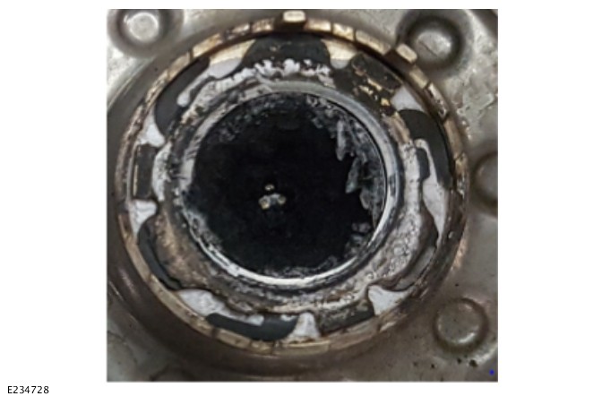
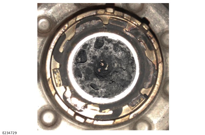
| APPLICATION | APPLICATION |
|---|---|
| 16 MY Eu_A | 16 MY NAS_A |
The OBD system monitors components and the functionality of the DEF supply and metering system. If a malfunction is detected a message centre warning is displayed. If no action is taken to rectify the warning malfunction, this will eventually lead to a 'No engine restart' situation
| DEF SUPPLY AND METERING SYSTEM MALFUNCTION INSTRUMENT CLUSTER WARNING MESSAGE | DTC(S) | PURPOSE AND CAUSE | ACTION |
|---|---|---|---|
|
NOTE:
The following DTC(s) are related to the DEF SUPPLY AND METERING SYSTEM and will be responsible for the Instrument cluster warning message(s) seen in this table
|
|
|
|
NOTE:
The following DTC(s) are related to the DEF SUPPLY AND METERING SYSTEM and will be responsible for the Instrument cluster warning message(s) seen in this table
|
|
|
|
NOTE:
The following DTC(s) are related to the DEF SUPPLY AND METERING SYSTEM and will be responsible for the Instrument cluster warning message(s) seen in this table
|
|
|
|
NOTE:
The following DTC(s) are related to the DEF SUPPLY AND METERING SYSTEM and will be responsible for the Instrument cluster warning message(s) seen in this table
|
|
|
|
NOTE:
The following DTC(s) are related to the DEF SUPPLY AND METERING SYSTEM and will be responsible for the Instrument cluster warning message(s) seen in this table
|
|
|
The following DEF supply and metering system malfunctions may trigger the message centre warning system
- Pressure build up in the supply line
- Metering/injection time to closed loop
- Over pressure in supply line
- Under pressure in supply line
- Injection valve open circuit
- SCR system relay open circuit
- Solenoid pump(s) open circuit
- Combined temperature/level sensor open circuit
- Missing communication with upstream NOx sensor (NAS variants only)
- Missing communication with downstream NOx sensor
| APPLICATION | APPLICATION |
|---|---|
| 16 MY Eu_B | 17 MY Eu_B |
The level of DEF in the tank is checked through the Instrument Cluster (IC) menu. When selected the message centre displays the approximate estimated km/miles figure remaining, prior to emptying the tank
The DEF tank is fitted with combined temperature/ultrasonic level sensors. Circuit continuity and plausibility of the signals received are checked within the ECM. An ultrasonic “no echo malfunction” is set if no valid echo from the ultrasonic sensor is detected during a predefined time. This typically happens when the ultrasonic signal of the sensor is blocked, or if the DEF tank is overfilled (the air pocket at the top of the DEF tank is no longer present). The vehicle message centre display's an advisory/warning system, which activates in low DEF conditions. If no corrective action is made, the engine will eventually not restart. The stages in the warning system are listed in the following tables
None of the listed stages will activate the MIL. The stages are automatically cleared if the DEF level is increased
| LOW DEF LEVEL INSTRUMENT CLUSTER WARNING MESSAGE | DTC(S) | PURPOSE AND CAUSE | ACTION |
|---|---|---|---|
|
P2BAE-00 |
|
Add diesel exhaust fluid |
|
P2BAE-00 and P2BAE-02 (17MY on) |
|
Add diesel exhaust fluid |
|
P2BAF-00 and P2BAE-00 and P2BAE-02 (17MY on) |
|
Add a minimum 3 litres of diesel exhaust fluid |
|
P2BAE-00 and P2BAE-02 (17MY on) and P2BAF-00 and P2BAF-02 (17MY on) |
|
Add a minimum 3 litres of diesel exhaust fluid |
|
P241D-00 and P2BAE-00 and P2BAE-02 (17MY on) and P2BAF-00 and P2BAF-02 (17MY on) and P2BAF-04 (17MY on) |
|
|
| APPLICATION | APPLICATION |
|---|---|
| 16 MY Eu_B | 17 MY Eu_B |
| INCORRECT DEF QUALITY INSTRUMENT CLUSTER WARNING MESSAGE | DTC(S) | PURPOSE AND CAUSE | ACTION |
|---|---|---|---|
|
P2BA9-00 and / or P2BA9-67 and / or P2BA9-92 and P2BAE and P2BAE-02 (17MY on) |
|
|
|
P2BA9-00 and / or P2BA9-67 and / or P2BA9-92 P2BAF-00 and P2BAE-00 and P2BAE-02 (17MY on) |
|
|
|
P2BA9-00 and / or P2BA9-67 and / or P2BA9-92 P2BAE-00 and P2BAE-02 (17MY on) and P2BAF-00 and P2BAF-02 (17MY on) |
|
|
|
P2BA9-00 and / or P2BA9-67 and / or P2BA9-92 P241D-00 and P2BAE-00 and P2BAE-02 (17MY on) and P2BAF-00 and P2BAF-02 (17MY on) and P2BAF-04 (17MY on) |
|
|
Prior to the NOx sensor and the monitoring function becoming operational, the sensor must have reached its 'dew point'. This is the point where the moisture content in the exhaust gas has evaporated and can no longer damage the NOx sensor. In normal ambient conditions, this process typically takes around 6 to 10 minutes. If a malfunction is detected during the operation of the NOx sensor, a reversible fault is stored. If a malfunction is detected over two (NAS variants) or three (EU6 variants) consecutive drive cycles, a permanent fault is stored and the MIL is activated
The following monitoring is performed on the NOx sensors
- Signal plausibility and correction factor limits
- Circuit continuity between the sensor control unit and probe element
- Operating temperature reached after a defined heating period
The following components are connected to the ECM through a private CAN bus. The ECM provides a gateway, for communication to the vehicle CAN bus
- Heater control unit
- NOx sensor control unit(s)
The following CAN communication monitoring applies to these components
- Signal time-out
- Signal check sum
The DEF injector, DEF pump, temperature and level sensors are hardwired to the ECM and do not involve CAN communication
| SITUATION | CAUSE | ACTION |
|---|---|---|
|
|
|
-
Check for any outstanding campaigns or service bulletins for this customer concern prior to carrying out this pinpoint test.
-
The following pinpoint test must be completed in full and in the order shown.
A visual inspection of the Dosing Module face can be completed. If the 3 injector holes can be seen in the center of the DM then it can be refitted. The soot will naturally clean off at the next DPF Regen cycle. The level of soot seen will vary depending on at which point the vehicle is within the regeneration cycle
| APPLICATION | APPLICATION |
|---|---|
| 16 MY Eu_B | 17 MY Eu_B |
The OBD system monitors components and the functionality of the DEF supply and metering system. If a malfunction is detected a message centre warning is displayed. If no action is taken to rectify the warning malfunction, this will eventually lead to a 'No engine restart' situation
| DEF SUPPLY AND METERING SYSTEM MALFUNCTION INSTRUMENT CLUSTER WARNING MESSAGE | DTC(S) | PURPOSE AND CAUSE | ACTION |
|---|---|---|---|
|
NOTE:
The following DTC(s) are related to the DEF SUPPLY AND METERING SYSTEM and will be responsible for the Instrument cluster warning message(s) seen in this table
|
|
|
|
NOTE:
The following DTC(s) are related to the DEF SUPPLY AND METERING SYSTEM and will be responsible for the Instrument cluster warning message(s) seen in this table
|
|
|
|
NOTE:
The following DTC(s) are related to the DEF SUPPLY AND METERING SYSTEM and will be responsible for the Instrument cluster warning message(s) seen in this table
|
|
|
|
NOTE:
The following DTC(s) are related to the DEF SUPPLY AND METERING SYSTEM and will be responsible for the Instrument cluster warning message(s) seen in this table
|
|
|
|
NOTE:
The following DTC(s) are related to the DEF SUPPLY AND METERING SYSTEM and will be responsible for the Instrument cluster warning message(s) seen in this table
|
|
|
The following DEF supply and metering system malfunctions may trigger the message centre warning system
- Pressure build up in the supply line
- Metering/injection time to closed loop
- Over pressure in supply line
- Under pressure in supply line
- Injection valve open circuit
- SCR system relay open circuit
- Solenoid pump(s) open circuit
- Combined temperature/level sensor open circuit
- Missing communication with upstream NOx sensor (NAS variants only)
- Missing communication with downstream NOx sensor
| APPLICATION | APPLICATION |
|---|---|
| 16 MY NAS_B | 17 MY NAS_B |
The level of DEF in the tank is checked through the Instrument Cluster (IC) menu. When selected the message centre displays the approximate estimated km/miles figure remaining, prior to emptying the tank
The DEF tank is fitted with combined temperature/ultrasonic level sensors. Circuit continuity and plausibility of the signals received are checked within the ECM. An ultrasonic “no echo malfunction” is set if no valid echo from the ultrasonic sensor is detected during a predefined time. This typically happens when the ultrasonic signal of the sensor is blocked, or if the DEF tank is overfilled (the air pocket at the top of the DEF tank is no longer present). The vehicle message centre display's an advisory/warning system, which activates in low DEF conditions. If no corrective action is made, the engine will eventually not restart. The stages in the warning system are listed in the following tables
None of the listed stages will activate the MIL. The stages are automatically cleared if the DEF level is increased
| LOW DEF LEVEL INSTRUMENT CLUSTER WARNING MESSAGE | DTC(S) | PURPOSE AND CAUSE | ACTION |
|---|---|---|---|
|
P2BAE-00 |
|
Add diesel exhaust fluid |
|
P2BAE-00 and P2BAE-02 (17MY on) |
|
Add diesel exhaust fluid |
|
P2BAF-00 and P2BAE-00 and P2BAE-02 (17MY on) |
|
Add a minimum 3 litres of diesel exhaust fluid |
|
P241D-00and P2BAE-00 and P2BAE-02 (17MY on) and P2BAF-00 and P2BAF-02 (17MY on) and P2BAF-04 (17MY on) |
|
|
| APPLICATION | APPLICATION |
|---|---|
| 16 MY NAS_B | 17 MY NAS_B |
| INCORRECT DEF QUALITY INSTRUMENT CLUSTER WARNING MESSAGE | DTC(S) | PURPOSE AND CAUSE | ACTION |
|---|---|---|---|
|
P2BA9-67 and / or P2BA9-92 P2BAF-00 and P2BAE-00 and P2BAE-02 (17MY on) |
|
|
|
P2BA9-67 and / or P2BA9-92 P241D-00and P2BAE-00 and P2BAE-02 (17MY on) and P2BAF-00 and P2BAF-02 (17MY on) and P2BAF-04 (17MY on) |
|
|
Prior to the NOx sensor and the monitoring function becoming operational, the sensor must have reached its 'dew point'. This is the point where the moisture content in the exhaust gas has evaporated and can no longer damage the NOx sensor. In normal ambient conditions, this process typically takes around 6 to 10 minutes. If a malfunction is detected during the operation of the NOx sensor, a reversible fault is stored. If a malfunction is detected over two (NAS variants) or three (EU6 variants) consecutive drive cycles, a permanent fault is stored and the MIL is activated
The following monitoring is performed on the NOx sensors
- Signal plausibility and correction factor limits
- Circuit continuity between the sensor control unit and probe element
- Operating temperature reached after a defined heating period
The following components are connected to the ECM through a private CAN bus. The ECM provides a gateway, for communication to the vehicle CAN bus
- Heater control unit
- NOx sensor control unit(s)
The following CAN communication monitoring applies to these components
- Signal time-out
- Signal check sum
The DEF injector, DEF pump, temperature and level sensors are hardwired to the ECM and do not involve CAN communication
| SITUATION | CAUSE | ACTION |
|---|---|---|
|
|
|
-
Check for any outstanding campaigns or service bulletins for this customer concern prior to carrying out this pinpoint test.
-
The following pinpoint test must be completed in full and in the order shown.
A visual inspection of the Dosing Module face can be completed. If the 3 injector holes can be seen in the center of the DM then it can be refitted. The soot will naturally clean off at the next DPF Regen cycle. The level of soot seen will vary depending on at which point the vehicle is within the regeneration cycle
| APPLICATION | APPLICATION |
|---|---|
| 16 MY NAS_B | 17 MY NAS_B |
The OBD system monitors components and the functionality of the DEF supply and metering system. If a malfunction is detected a message centre warning is displayed. If no action is taken to rectify the warning malfunction, this will eventually lead to a 'No engine restart' situation
| DEF SUPPLY AND METERING SYSTEM MALFUNCTION INSTRUMENT CLUSTER WARNING MESSAGE | DTC(S) | PURPOSE AND CAUSE | ACTION |
|---|---|---|---|
|
NOTE:
The following DTC(s) are related to the DEF SUPPLY AND METERING SYSTEM and will be responsible for the Instrument cluster warning message(s) seen in this table
|
|
|
|
NOTE:
The following DTC(s) are related to the DEF SUPPLY AND METERING SYSTEM and will be responsible for the Instrument cluster warning message(s) seen in this table
|
|
|
The following DEF supply and metering system malfunctions may trigger the message centre warning system
- Pressure build up in the supply line
- Metering/injection time to closed loop
- Over pressure in supply line
- Under pressure in supply line
- Injection valve open circuit
- SCR system relay open circuit
- Solenoid pump(s) open circuit
- Combined temperature/level sensor open circuit
- Missing communication with upstream NOx sensor (NAS variants only)
- Missing communication with downstream NOx sensor
| QUESTION | ANSWER |
|---|---|
| Is the inducement system only triggered by low levels of DEF? | NO. The inducement system make sures correct operation of the SCR/DEF system. It monitors (1) DEF level (2) DEF quality (3) Dosing hardware. A low level (1) OR a malfunction detected in area (2) or (3) will trigger the inducement system. The warning messages states the malfunction. |
| Is the number of engine restarts limited while the vehicle is driven with the inducement system on? | NO. The engine can be stopped / started indefinitely until the message "No Engine Restart Possible" shows. |
| Is there sufficient warning before the engine does NOT restart? | YES. The mileage countdown shown by the inducement system is guaranteed mileage before the no restart condition. The vehicle can be driven on the final "No Engine Restart Possible" warning until the engine is stopped by the driver. An engine stall is NOT counted as an engine stop. NOTE: Though an ECO stop is not counted as an engine stop; ECO stop functionality is NO longer available when the final "No Engine Restart Possible" warning shows. |
| Can the inducement system "heal" if the malfunction no longer exists? | YES. The inducement system will heal automatically - warnings will disappear - if the malfunction no longer exists. If the malfunction was to re-occur within 40 hours of operation, the inducement system will resume at the mileage it was left. This is to prevent long term tampering with the system. |
| Are the P2BAE / P2BAF DTC(s) to represent a malfunction? | NO. The P2BAE / P2BAF DTC(s) only help to understand at what level of inducement the vehicle currently is. |
| Is the low DEF level a malfunction? | NO. This is why no other DTC(s) than P2BAE / P2BAF - to represent the level of inducement the vehicle is in - are visible when low DEF occurs. The DEF tank shall be topped up with necessary volumes. |
| Is there a minimum top up volume when DEF level is low? | YES. More than 3 litres DEF or 2 "KRUSE" bottles or 1 US gallon bottle are necessary to activate top up detection. This also applies when the vehicle does NOT restart because of low DEF level. |
For a complete list of all diagnostic trouble codes that could be set on this vehicle, please refer to Section 100-00.
EXHAUST SYSTEM - TDV6 3.0L DIESEL - GEN 2
CATALYTIC CONVERTER (G1605340)
- 17.50.01
- CATALYTIC CONVERTER - RENEW
- 3000 CC, TDV6
- 0.70
- USED WITHINS
SPECIAL TOOL(S)
100-051
Cutter, Exhaust Pipe
PART(S)
| STEP | PART NAME | QUANTITY |
|---|---|---|
| Removal Step 8 | Exhaust downpipe gasket(s) | 1 |
| Installation Step 2 | Exhaust clamp | 1 |
Observe due care when working near a hot exhaust system.
Removal steps in this procedure may contain installation details.
-
Raise and support the vehicle.WARNING:
Make sure to support the vehicle with axle stands.
Refer to:Lifting (100-02 Jacking and Lifting, Description and Operation).
-
Refer to:Front Muffler (309-00A Exhaust System - TDV6 3.0L Diesel - Gen 2, Removal and Installation).
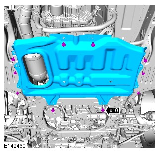
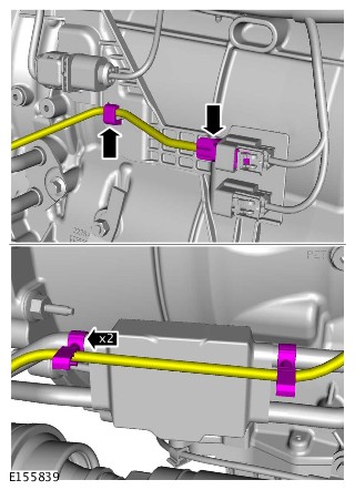
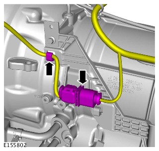
-
-
Special Tool(s): 100-051
-
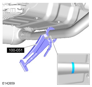
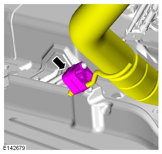
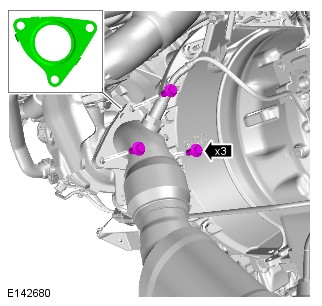
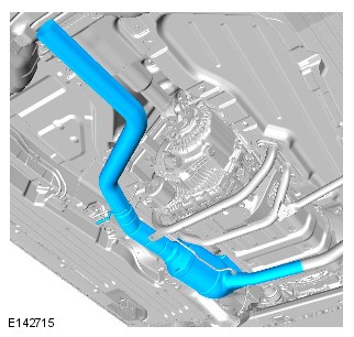
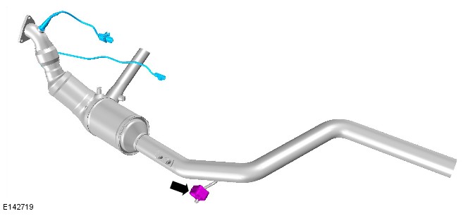
-
CAUTIONS:
-
If accidentally dropped or knocked install a new sensor.
-
Make sure the Heated Oxygen Sensor (HO2S) wiring harness is not twisted more than 180 degrees and is not in contact with either the exhaust or driveshaft.
-
Make sure the anti-seize compound does not contact the HO2S tip.
To install, reverse the removal procedure.NOTE:If the original sensor is to be installed, apply lubricant meeting specification ESE-M12A4-A to the thread of the sensor.
-
-
NOTES:
-
Make sure that all the component mating faces are clean.
-
Check for leaks, when engine is warm.
Torque: 55Nm -
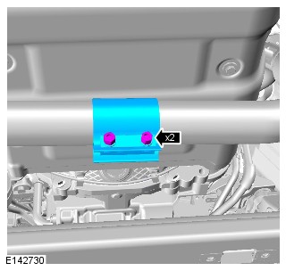
EXHAUST SYSTEM - TDV6 3.0L DIESEL - GEN 2
DIESEL PARTICULATE FILTER - VEHICLES WITHOUT: DIESEL EXHAUST FLUID (G1875941)
- 17.50.20
- DIESEL PARTICULATE FILTER - RENEW
- 3000 CC, TDV6, WITH DIESEL EXHAUST FLUID
- 1.20
- USED WITHINS
SPECIAL TOOL(S)

310-121
Wrench, H02S
GENERAL EQUIPMENT
| EQUIPMENT NAME |
|---|
| Land Rover diagnostic equipment |
PART(S)
| STEP | PART NAME | QUANTITY |
|---|---|---|
| Installation Step 4 | Diesel Particulate Filter (DPF) to exhaust gasket | 1 |
| Installation Step 5 | Diesel Particulate Filter (DPF) to exhaust gasket | 1 |
| Installation Step 6 | EGR pipe to DPF gasket | 1 |
| Installation Step 6 | EGR pipe to DPF clamp | 1 |
Observe due care when working near a hot exhaust system.
If the Selective Catalyst Reduction (SCR) catalytic converter has previously been replaced, then the complete SCR catalytic converter and Diesel Particulate Filter (DPF) assembly should be replaced.
-
This procedure contains some variation in the illustrations depending on the vehicle specification, but the essential information is always correct.
-
This procedure contains illustrations showing certain components removed to provide extra clarity.
- Raise and support the vehicle on a suitable 2 post lift.
Refer to:Lifting (100-02 Jacking and Lifting, Description and Operation).
- Remove the front driveshaft.
Refer to:Front Driveshaft - TDV6 3.0L Diesel /TDV6 3.0L Diesel - Gen 1.5/TDV6 3.0L Diesel - Gen 2 (205-01 Driveshaft, Removal and Installation).

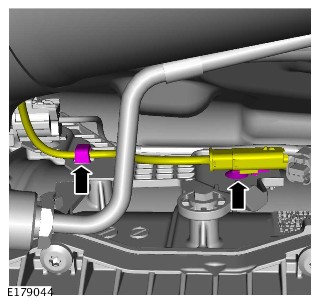
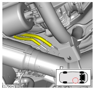
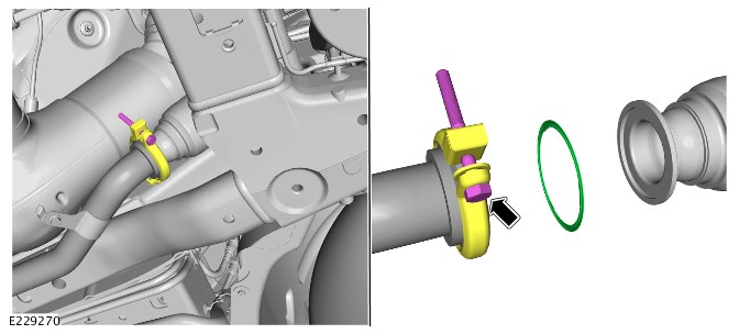
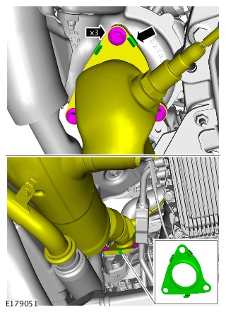
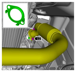
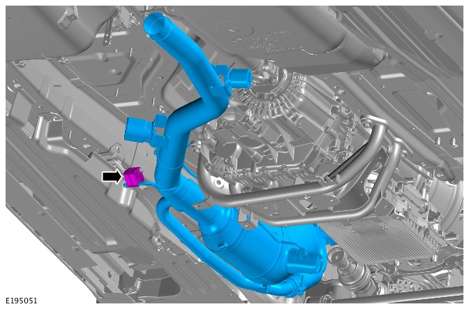

-
Remove the Heated Oxygen Sensor (H02S).Special Tool(s): 310-121

-
CAUTIONS:
-
If accidentally dropped or knocked install a new sensor.
-
Make sure the Heated Oxygen Sensor (HO2S) wiring harness is not twisted more than 180 degrees and is not in contact with either the exhaust or driveshaft.
-
Make sure the anti-seize compound does not contact the HO2S tip.
Install and tighten the Heated Oxygen Sensor (H02S).NOTE:If the original sensor is to be installed, apply lubricant meeting specification ESE-M12A4-A to the thread of the sensor.
Torque: 48Nm -
- Install and tighten the 2 exhaust gas temperature sensors.
Torque: 35Nm
- Install the DPF.
-
NOTE:
Vehicles with twin turbocharger system:
- Install a new DPF to turbocharger gasket.
- Install and tighten the 2 bolts.
Torque: 28Nm
-
- Install a new DPF to turbocharger gasket.
- Install and tighten the 3 bolts.
Torque: 28Nm
-
- Install a new Exhaust Gas Recirculation (EGR) pipe gasket.
- Install the EGR pipe.
- Install a new EGR pipe clamp.
- Tighten the bolt.
Torque: 9Nm
- Install the pipes.
- Connect the electrical connectors and secure the wiring harness.
- Install the front driveshaft.
Refer to:Front Driveshaft - TDV6 3.0L Diesel /TDV6 3.0L Diesel - Gen 1.5/TDV6 3.0L Diesel - Gen 2 (205-01 Driveshaft, Removal and Installation).
- If a new DPF is installed. Use the Jaguar Land Rover approved diagnostic equipment, complete Diesel Particulate Filter replacement application and prime the diesel exhaust fluid system.
EXHAUST SYSTEM - TDV6 3.0L DIESEL - GEN 2
DIESEL PARTICULATE FILTER - VEHICLES WITH: DIESEL EXHAUST FLUID (G1889531)
- 17.50.20
- DIESEL PARTICULATE FILTER - RENEW
- 3000 CC, TDV6, WITH DIESEL EXHAUST FLUID
- 1.20
- USED WITHINS
SPECIAL TOOL(S)
100-051
Cutter, Exhaust Pipe
310-121
Wrench, H02S
GENERAL EQUIPMENT
| EQUIPMENT NAME |
|---|
| Jaguar Land Rover approved diagnostic equipment |
PART(S)
| STEP | PART NAME | QUANTITY |
|---|---|---|
| Installation Step 5 | Diesel Particulate Filter (DPF) to exhaust gasket | 1 |
| Installation Step 6 | Diesel Particulate Filter (DPF) to exhaust gasket | 1 |
| Installation Step 7 | EGR pipe to DPF gasket | 1 |
| Installation Step 7 | EGR pipe to DPF clamp | 1 |
Observe due care when working near a hot exhaust system.
If the Selective Catalyst Reduction (SCR) catalytic converter has previously been replaced, then the complete SCR catalytic converter and Diesel Particulate Filter (DPF) assembly should be replaced.
-
This procedure contains some variation in the illustrations depending on the vehicle specification, but the essential information is always correct.
-
This procedure contains illustrations showing certain components removed to provide extra clarity.
- Raise and support the vehicle on a suitable 2 post lift.
Refer to:Lifting (100-02 Jacking and Lifting, Description and Operation).
- Remove the front driveshaft.
Refer to:Front Driveshaft - TDV6 3.0L Diesel /TDV6 3.0L Diesel - Gen 1.5/TDV6 3.0L Diesel - Gen 2 (205-01 Driveshaft, Removal and Installation).
-
CAUTION:
If the SCR catalytic converter has previously been replaced, then the complete exhaust system should be replaced.
NOTE:This step should be used as a reference only.
- Illustration E241112 shows the mandatory service cut lines for the exhaust system.
- Cut the exhaust at A for DPF replacement.
- Cut the exhaust at B for SCR catalytic converter replacement.
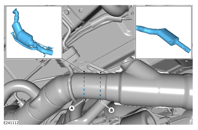
-
WARNING:
Make sure that the exhaust system is supported.
Using the special tool, cut the DPF in the position shown.Special Tool(s): 100-051
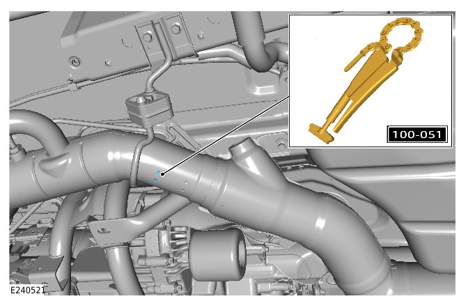
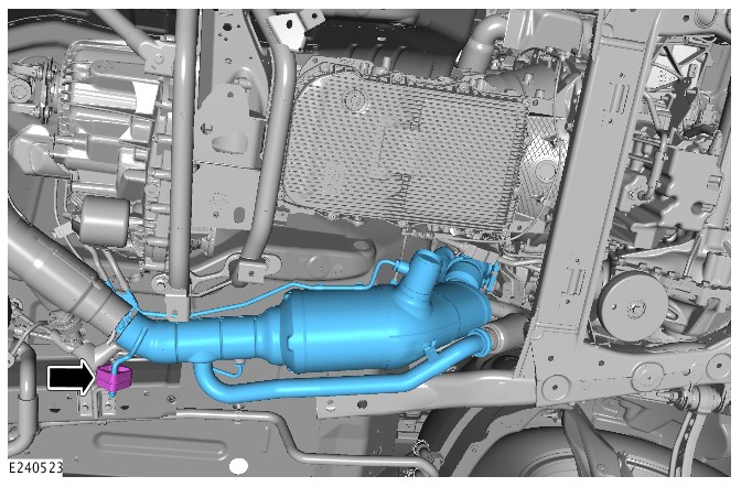
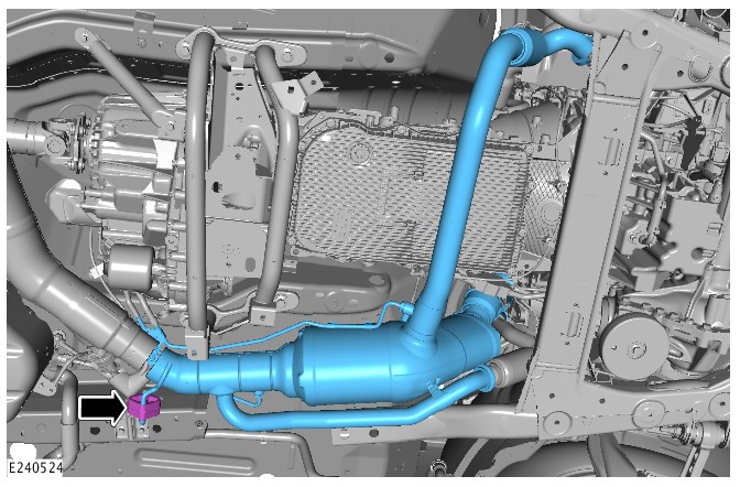
-
Remove the Heated Oxygen Sensor (HO2S).Special Tool(s): 310-121
-
CAUTIONS:
-
If accidentally dropped or knocked install a new sensor.
-
Make sure the HO2S wiring harness is not twisted more than 180 degrees and is not in contact with either the exhaust or driveshaft.
-
Make sure the anti-seize compound does not contact the HO2S tip.
Install and tighten the HO2S.NOTE:If the original sensor is to be installed, apply lubricant meeting specification ESE-M12A4-A to the thread of the sensor.
Torque: 48Nm -
- Install and tighten the 2 exhaust gas temperature sensors.
Torque: 35Nm
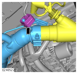
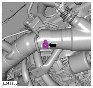
-
NOTE:
Vehicles with twin turbocharger system:
- Install a new DPF to turbocharger gasket.
- Install and tighten the 2 bolts.
Torque: 28Nm
-
- Install a new DPF to turbocharger gasket.
- Install and tighten the 3 bolts.
Torque: 28Nm
-
- Install a new EGR pipe gasket.
- Install the EGR pipe.
- Install a new EGR pipe clamp.
- Tighten the bolt.
Torque: 9Nm
- Install the pipes.
- Connect the electrical connectors and secure the wiring harness.
- Install the front driveshaft.
Refer to:Front Driveshaft - TDV6 3.0L Diesel /TDV6 3.0L Diesel - Gen 1.5/TDV6 3.0L Diesel - Gen 2 (205-01 Driveshaft, Removal and Installation).
- If a new DPF is installed. Using the Jaguar Land Rover (JLR) approved diagnostic equipment, complete DPF replacement application.
EXHAUST SYSTEM - TDV6 3.0L DIESEL - GEN 2 (G1605342)
- 30.10.01
- EXHAUST SYSTEM - RENEW
- 3000 CC, TDV6, HYBRID, WITH PARTICULATE FILTER
- 0.80
- USED WITHINS
- 30.10.01
- EXHAUST SYSTEM - RENEW
- 3000 CC, TDV6, WITH PARTICULATE FILTER, WITH DIESEL EXHAUST FLUID
- 2.10
- USED WITHINS
PART(S)
| STEP | PART NAME | QUANTITY |
|---|---|---|
| Removal Step 6 | Exhaust downpipe gasket(s) | 1 |
| Removal Step 7 | Exhaust downpipe gasket(s) | 1 |
Observe due care when working near a hot exhaust system.
-
Removal steps in this procedure may contain installation details.
-
Some variation in the illustrations may occur, but the essential information is always correct.
-
Raise and support the vehicle.WARNING:
Make sure to support the vehicle with axle stands.
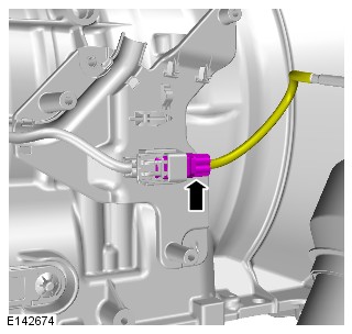
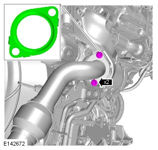
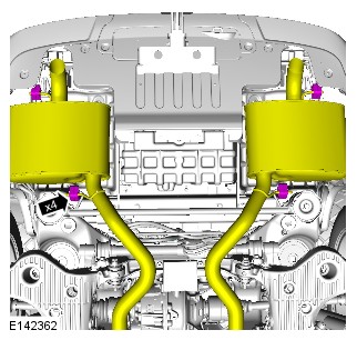
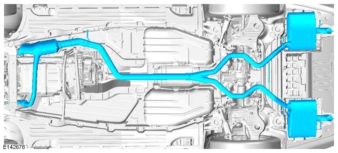
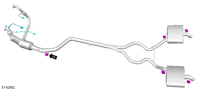
- To install, reverse the removal procedure.
EXHAUST SYSTEM - TDV6 3.0L DIESEL - GEN 2 (G1875429)
- 30.10.01
- EXHAUST SYSTEM - RENEW
- 3000 CC, TDV6, HYBRID, WITH PARTICULATE FILTER
- 0.80
- USED WITHINS
- 30.10.01
- EXHAUST SYSTEM - RENEW
- 3000 CC, TDV6, WITH PARTICULATE FILTER, WITH DIESEL EXHAUST FLUID
- 2.10
- USED WITHINS
SPECIAL TOOL(S)
310-121
Wrench, H02S
PART(S)
| STEP | PART NAME | QUANTITY |
|---|---|---|
| Removal Step 8 | EGR pipe to DPF gasket | 1 |
| Removal Step 9 | Right exhaust downpipe to DPF gasket | 1 |
| Removal Step 10 | EGR pipe to DPF gasket | 1 |
Observe due care when working near a hot exhaust system.
Removal steps in this procedure may contain installation details.
-
Raise and support the vehicle.WARNING:
Make sure to support the vehicle with axle stands.
-
Refer to:Front Driveshaft - TDV6 3.0L Diesel /TDV6 3.0L Diesel - Gen 1.5/TDV6 3.0L Diesel - Gen 2 (205-01 Driveshaft, Removal and Installation).

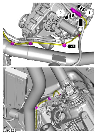
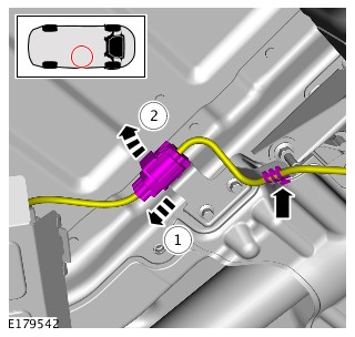
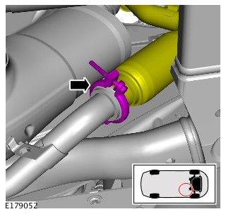
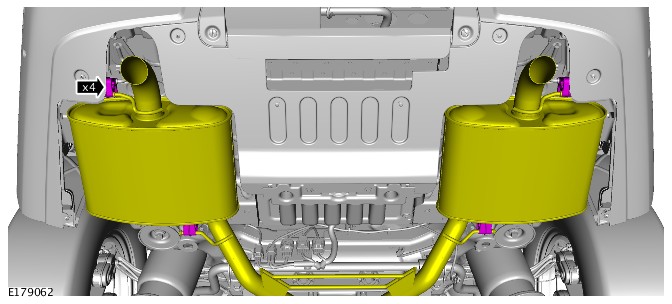
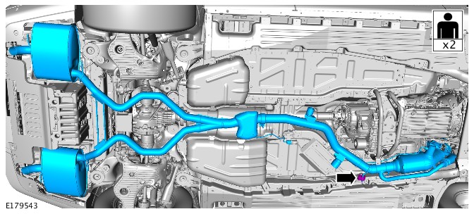
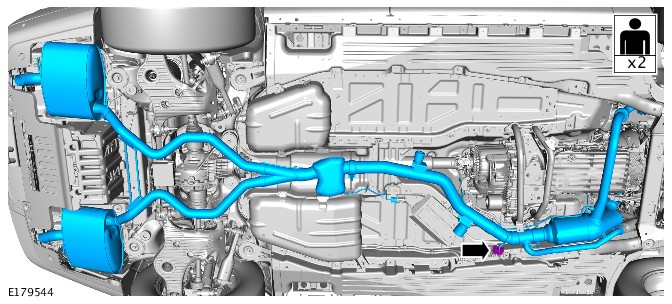
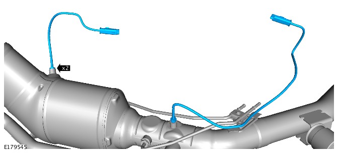
-
Special Tool(s): 310-121Torque: 48Nm
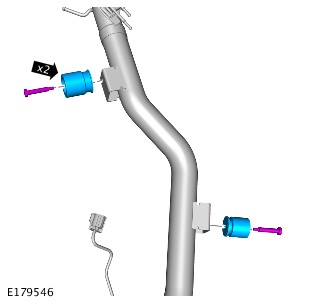
- To install, reverse the removal procedure.
EXHAUST SYSTEM - TDV6 3.0L DIESEL - GEN 2 (G1889597)
- 30.10.01
- EXHAUST SYSTEM - RENEW
- 3000 CC, TDV6, HYBRID, WITH PARTICULATE FILTER
- 0.80
- USED WITHINS
- 30.10.01
- EXHAUST SYSTEM - RENEW
- 3000 CC, TDV6, WITH PARTICULATE FILTER, WITH DIESEL EXHAUST FLUID
- 2.10
- USED WITHINS
SPECIAL TOOL(S)
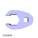
JLR-303-1646
Post Selective Catalyst Reduction Soot Sensor - Remover/Installer
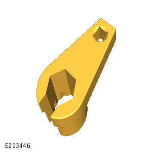
JLR-303-1666
Remover/Installer, NOx/Oxygen Sensor
PART(S)
| STEP | PART NAME | QUANTITY |
|---|---|---|
| Installation Step 8 | Right exhaust downpipe to DPF gasket | 1 |
| Installation Step 9 | Exhaust downpipe gasket(s) | 1 |
| Installation Step 10 | EGR pipe to DPF gasket | 1 |
| Installation Step 18 | Diesel exhaust fluid injector clamp kit | 1 |
Observe due care when working near a hot exhaust system.
-
This procedure contains some variation in the illustrations depending on the vehicle specification, but the essential information is always correct.
-
This procedure contains illustrations showing certain components removed to provide extra clarity.
- Raise and support the vehicle on a suitable 2 post lift.
Refer to:Lifting (100-02 Jacking and Lifting, Description and Operation).
- Remove the front driveshaft.
Refer to:Front Driveshaft - TDV6 3.0L Diesel /TDV6 3.0L Diesel - Gen 1.5/TDV6 3.0L Diesel - Gen 2 (205-01 Driveshaft, Removal and Installation).


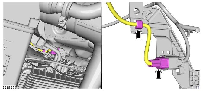
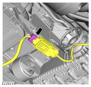
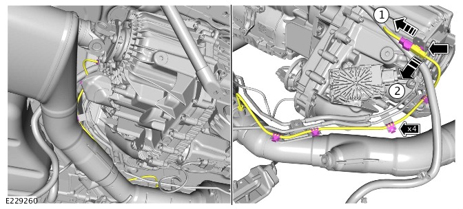
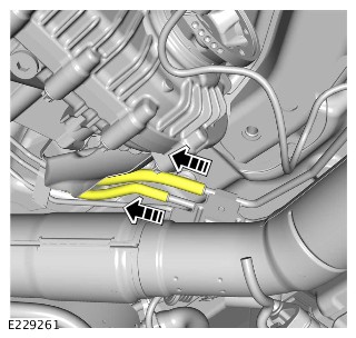


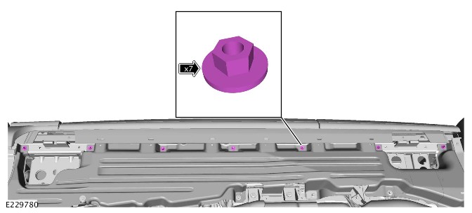
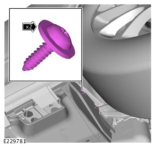
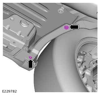
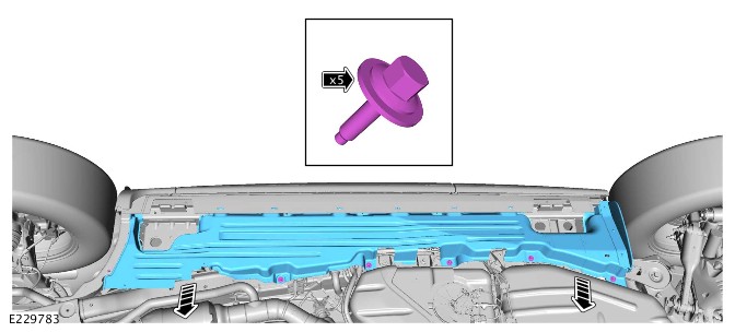
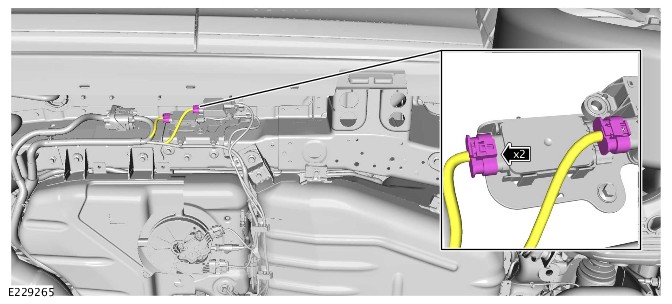
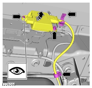
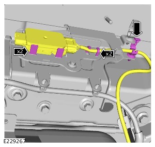
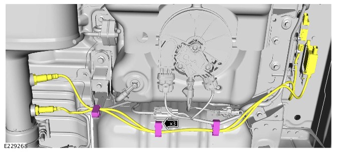
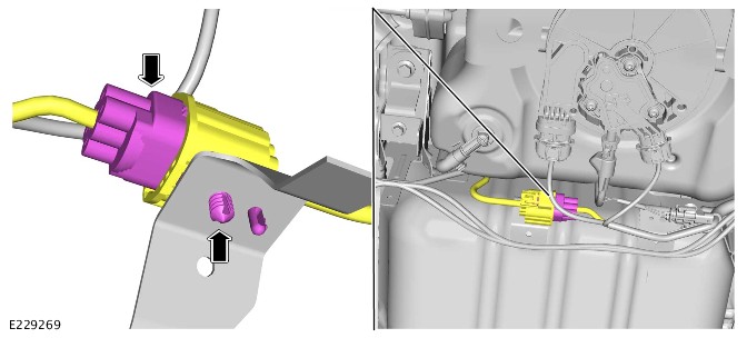
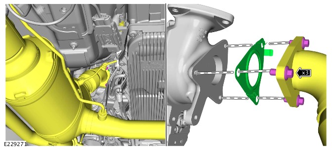
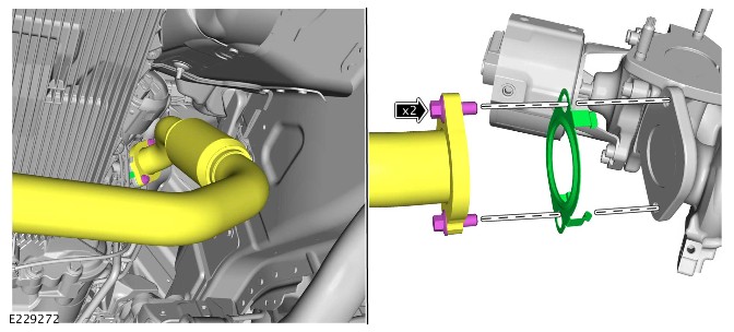
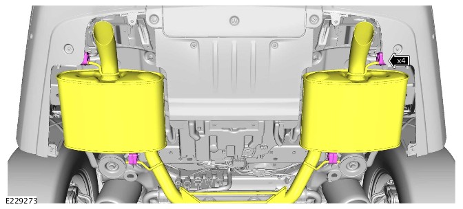
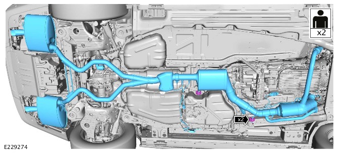
-
NOTE:
Only do the following step(s), if a new component is to be installed.
Using the special tool remove the Heated Oxygen Sensor (HO2S).Special Tool(s): JLR-303-1666
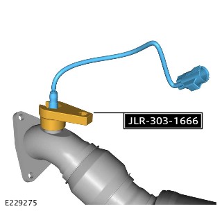
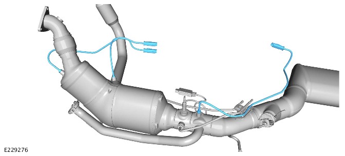
-
Using the special tool, remove the pre SCR NOx sensor.Special Tool(s): JLR-303-1666
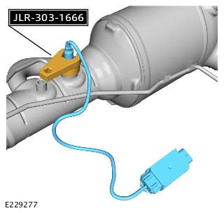
-
Using the special tool, remove the particulate matter sensor.Special Tool(s): JLR-303-1646
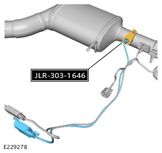
-
Using the special tool, remove the post SCR NOx sensor.Special Tool(s): JLR-303-1666
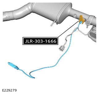
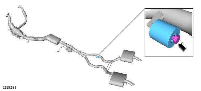
-
- Install the damper.
- Install and tighten the bolt.
Torque: 22Nm
- Using the special tool, install the post SCR NOx sensor.
Torque: 48Nm
- Using the special tool, install the particulate matter sensor.
Torque: 48Nm
- Using the special tool, install the pre SCR NOx sensor.
Torque: 48Nm
- Install the 3 exhaust gas temperature sensors.
Torque: 35Nm
- Using the special tool install the HO2S.
Torque: 48Nm
-
- With assistance, install the exhaust system.
- Connect the 6 exhaust hangers.
-
- Connect the exhaust system on the right side.
- Install a new gasket.
- Install and tighten the 2 bolts.
Torque: 28Nm
-
- Connect the exhaust system on the left side.
- Install a new gasket.
- Install and tighten the 3 bolts.
Torque: 28Nm
-
- Connect the Exhaust Gas Recirculation (EGR) pipe and exhaust manifold flanges.
- Install the clamp and tighten the bolt.
Torque: 9Nm
-
CAUTION:
Take extra care not to damage the component.
- Connect the wiring harness to the bracket.
- Connect the electrical connector to the exhaust pressure control valve.
-
Connect the wiring harness to the 3 clips.CAUTION:
Take extra care not to damage the clips.
-
CAUTION:
Take extra care not to damage the clips.
- Install the post SCR NOx sensor module to the bracket.
- Connect the wiring harness to the 3 clips.
-
- Install the particulate matter sensor module to the bracket.
- Connect the wiring harness to the 2 clips.
- Install and tighten the bolt.
Torque: 10Nm
- Connect the 2 electrical connectors.
-
NOTE:
Before installing the bolts, note the thread size of the bolts.
- Install the DEF tank cover.
- Install and tighten the 5 bolts.
Torque: 12Nm
- Connect the wiring harness to the clip.
-
- Install the body side undershield.
- Install and tighten the 7 nuts.
Torque: 9Nm
- Install and tighten the 5 bolts.
Torque: 9Nm
- Install and tighten the 2 screws on the front section of the body side undershield.
Torque: 2.8Nm
- Install and tighten the 2 screws on the rear section of the body side undershield.
Torque: 2.8Nm
- Install the 6 retainers to the rocker panel moulding.
-
CAUTION:
Make sure that the area around the component is clean and free of foreign material.
- Install a new DEF injector clamp.
- Install the DEF injector.
- Tighten the DEF injector clamp bolt.
Torque: 5Nm
- Connect the electrical connector.
- Connect the DPF high-pressure and low-pressure hoses.
-
- Install the wiring harness to the 4 clips.
- Install the electrical connector to the bracket.
- Connect the electrical connector to the rear exhaust temperature sensor.
- Connect the electrical connector to the pre SCR NOx sensor.
-
- Install the HO2S wiring harness to the bracket.
- Connect the HO2S electrical connector.
-
- Install the pre and post catalyst temperature sensor wiring harness to the bracket.
- Install the pre and post catalyst temperature sensor electrical connectors to the bracket.
- Connect the 2 electrical connectors to the pre and post catalyst temperature sensor.
- Install the front driveshaft.
Refer to:Front Driveshaft - TDV6 3.0L Diesel /TDV6 3.0L Diesel - Gen 1.5/TDV6 3.0L Diesel - Gen 2 (205-01 Driveshaft, Removal and Installation).
EXHAUST SYSTEM - TDV6 3.0L DIESEL - GEN 2
REAR MUFFLER (G1509412)
- 30.10.22
- REAR SILENCER - RENEW
- 3000 CC, TDV6
- 0.20
- USED WITHINS
SPECIAL TOOL(S)
100-051
Cutter, Exhaust Pipe
PART(S)
| STEP | PART NAME | QUANTITY |
|---|---|---|
| Installation Step 1 | Rear exhaust silencer clamp | 1 |
Observe due care when working near a hot exhaust system.
-
This procedure shows the right rear silencer, left rear silencer is similar.
-
This procedure contains some variation in the illustrations depending on the vehicle specification, but the essential information is always correct.
-
This procedure contains illustrations showing certain components removed to provide extra clarity.
- Raise and support the vehicle on a suitable 2 post lift.
Refer to:Lifting (100-02 Jacking and Lifting, Description and Operation).
-
CAUTION:
Make sure that the exhaust system is supported with suitable retaining straps.
- Using the special tool, cut the exhaust pipe at the marked position.
Special Tool(s): 100-051
- Using the special tool, cut the exhaust pipe at the marked position.
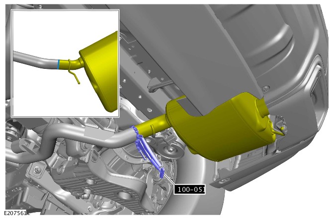
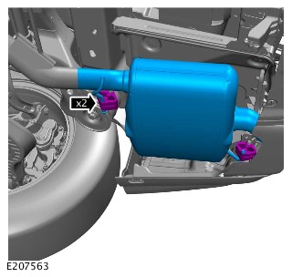
-
-
Install the rear silencer.WARNING:
Make sure that any corrosion or dirt is removed from the mating surfaces.
- Install the exhaust clamp finger tight.
-
-
- Position the rear silencer in the correct position as illustrated and fully tighten the exhaust clamp.
Torque: 40Nm
- Position the rear silencer in the correct position as illustrated and fully tighten the exhaust clamp.
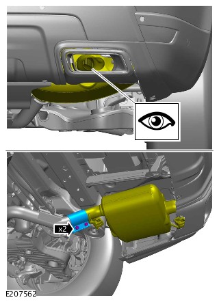
EXHAUST SYSTEM - TDV6 3.0L DIESEL - GEN 2
FRONT MUFFLER (G1962658)
- 30.10.22.58
- REAR SILENCER - RENEW - SVR VEHICLES
- ALL DERIVATIVES
- 2.80
- USED WITHINS
Observe due care when working near a hot exhaust system.
Removal steps in this procedure may contain installation details.
-
Raise and support the vehicle.WARNING:
Make sure to support the vehicle with axle stands.
-
NOTES:
-
The procedure must be carried out on both sides.
-
Step only applies if you are installing a new component.
Refer to:Rear Muffler (309-00A Exhaust System - TDV6 3.0L Diesel - Gen 2, Removal and Installation). -
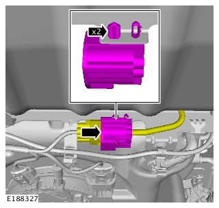

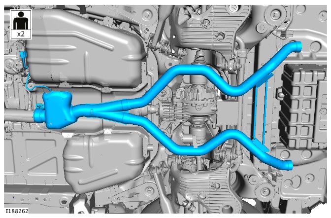
-
WARNING:
Make sure that any corrosion or dirt is removed from the mating surfaces.
To install, reverse the removal procedure.NOTE:Check for leaks, when engine is warm.
EXHAUST SYSTEM - TDV6 3.0L DIESEL - GEN 2
SELECTIVE CATALYST REDUCTION CATALYTIC CONVERTER (G1935639)
- 17.50.01
- CATALYTIC CONVERTER - RENEW
- 3000 CC, TDV6
- 0.70
- USED WITHINS
- 17.50.90
- UNDERFLOOR CATALYTIC CONVERTER - RENEW
- 3000 CC, TDV6, DIESEL
- 0.30
- USED WITHINS
SPECIAL TOOL(S)
100-051
Cutter, Exhaust Pipe
JLR-303-1666
Remover/Installer, NOx/Oxygen Sensor
PART(S)
| STEP | PART NAME | QUANTITY |
|---|---|---|
| Installation Step 3 | Diesel exhaust fluid injector clamp kit | 1 |
| Installation Step 4 | Exhaust clamp | 1 |
Observe due care when working near a hot exhaust system.
If the Diesel Particulate Filter (DPF) has previously been replaced, then the complete Selective Catalyst Reduction (SCR)catalytic converter and DPF assembly should be replaced.
-
This procedure contains some variation in the illustrations depending on the vehicle specification, but the essential information is always correct.
-
This procedure contains illustrations showing certain components removed to provide extra clarity.
- Raise and support the vehicle on a suitable 2 post lift.
Refer to:Lifting (100-02 Jacking and Lifting, Description and Operation).
-
CAUTION:
Make sure to support the SCR NOx sensor with suitable retaining straps.
Using the special tool, remove the post SCR NOx sensor.Install the Special Tool(s): JLR-303-1666
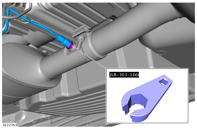
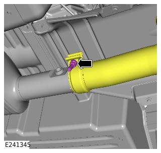
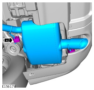
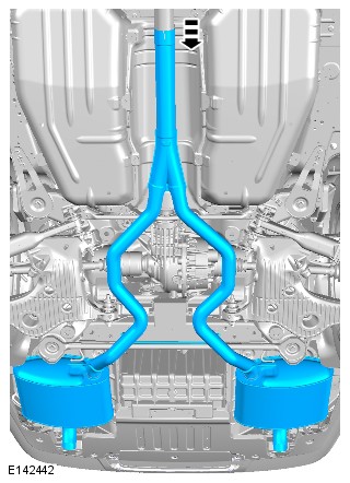
-
CAUTION:
If the DPF has previously been replaced, then the complete exhaust system should be replaced.
NOTE:This step should be used as a reference only.
- Illustration E241112 shows the mandatory service cut lines for the exhaust system.
- Cut the exhaust at A for DPF replacement.
- Cut the exhaust at B for SCR catalytic converter replacement.
-
WARNING:
Make sure that the exhaust system is supported.
Using the special tool, cut the SCR catalytic converter in the position shown.Special Tool(s): 100-051
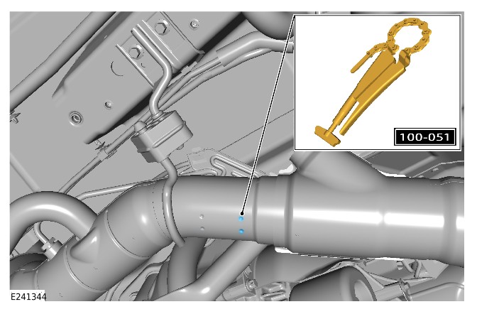
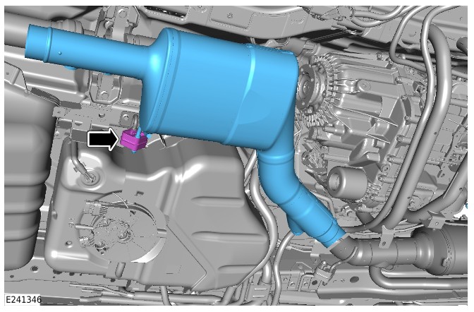
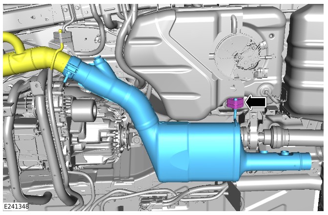
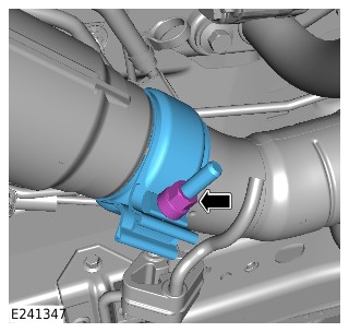
-
CAUTION:
Make sure that the area around the component is clean and free of foreign material.
- Install a new DEF injector clamp.
- Install the DEF injector.
- Tighten the DEF injector clamp bolt.
Torque: 5Nm
- Connect the electrical connector.
-
CAUTION:
Make sure the exhaust and clamp are installed to the correct position.
- Install a new exhaust clamp.
- Install the exhaust.
- Tighten the exhaust to SCR catalytic converter clamp.
Torque: 55Nm
- Using the special tool, instal the post SCR NOx sensor.
Install the Special Tool(s): JLR-303-1666