WSM-19601 - Workshop manual Range Rover Sport (LW) 2016
ANTI-THEFT - ACTIVE (G1569170)
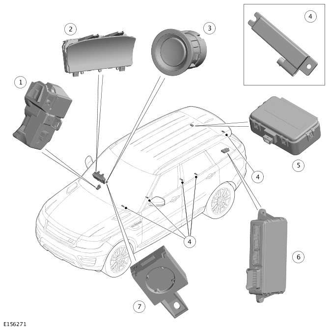
COMPONENT LOCATION

| ITEM | DESCRIPTION |
|---|---|
| 1 | Front overhead console |
| 2 | Rear right door module |
| 3 | Volumetric sensor |
| 4 | Rear right door latch |
| 5 | RF (Radio Frequency) receiver |
| 6 | Right tailgate latch |
| 7 | Tailgate Control Module (TCM) |
| 8 | Keyless Vehicle Module (KVM) |
| 9 | Left tailgate latch |
| 10 | Rear left door latch |
| 11 | Rear left door module |
| 12 | Front left door latch |
| 13 | Passenger Door Module (PDM) |
| 14 | Smartkey |
| 15 | Central Junction Box (CJB) |
| 16 | Immobilizer Antenna Unit (IAU) |
| 17 | Hood switch |
| 18 | Battery Back-Up Sounder (BBUS) |
| 19 | Electric Steering Column Lock (ESCL) |
| 20 | Instrument Cluster (IC) |
| 21 | Driver Door Module (DDM) |
| 22 | Front right door latch |
The active anti-theft system monitors the hinged panels for unauthorized opening. In some markets the anti-theft system also incorporates monitoring of the vehicle interior and vehicle tilt sensing.
The active anti-theft alarm system is controlled by the following body system control modules:
- CJB
- Left and right front and rear door modules
- IC.
The CJB is the main controller in the system. The CJB controls the following security functions, in addition to other vehicle functions:
- Locking, double locking and unlocking
- Monitoring of hinged panel micro switches and panel ajar states
- Interior motion sensor
- BBUS or vehicle horns
- Passive arming and disarming
- Panic alarm function
- Smartkey transponder reading
- Interior lighting.
Two levels of vehicle anti-theft alarm are available; perimeter mode monitors all opening panels and volumetric mode (if fitted) monitors the vehicle interior for intrusion and it also incorporates a tilt sensor to monitor if the vehicle is being moved.
Volumetric mode and tilt sensing are not available in certain markets
The Smartkey provides the following functionality:
- Unlock (central unlock or single point entry)
- Lock and double lock
- Tailgate release
- Approach lighting
- Panic alarm.
The lock and unlock switches also control a 'lazy' lock and unlock feature which will automatically close or open the windows with an extended press of the applicable switch. This feature is only available in certain markets and is controlled in conjunction with the door modules.
Never double lock the vehicle with any person or animal inside.
Double locking is only available in certain markets.
The Smartkey contains an emergency access key. This can be used in the event of failure of the Smartkey or the vehicle battery to unlock the vehicle. The left door handle contains a concealed mechanical key barrel which can be used with the emergency key to access the vehicle. This will not disable the perimeter or interior alarm systems which will be activated when the door is opened. To cancel the alarm, the Smartkey must be held next to the IAU and the stop/start switch must be pressed.For additional information, refer to: Handles, Locks, Latches and Entry Systems (501-14 Handles, Locks, Latches and Entry Systems, Description and Operation).
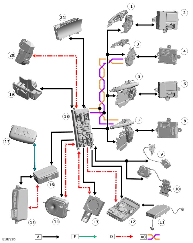
| ITEM | DESCRIPTION |
|---|---|
| 1 | Rear right door latch mechanism |
| 2 | Rear right door module |
| 3 | Front right door latch and mechanism |
| 4 | Driver Door Module (DDM) |
| 5 | Rear left door latch and mechanism |
| 6 | Rear left door module |
| 7 | Front left door latch and mechanism |
| 8 | Passenger Door Module (PDM) |
| 9 | Left tailgate latch |
| 10 | Right tailgate latch |
| 11 | Volumetric sensor |
| 12 | Front overhead console |
| 13 | Immobilizer Antenna Unit (IAU) |
| 14 | Battery Back-Up Sounder (BBUS) |
| 15 | Keyless Vehicle Module (KVM) |
| 16 | Radio Frequency (RF) receiver |
| 17 | Smartkey |
| 18 | Central Junction Box (CJB) |
| 19 | Hood latch |
| 20 | Electric Steering Column Lock (ESCL) |
| 21 | Instrument Cluster (IC) |
PRINCIPLES OF OPERATION
The CJB automatically arms and disarms the active anti-theft system when it operates the Central Locking System (CLS).
On vehicles without a Volumetric sensor, only the perimeter mode is available to monitor the hinged panels and the validity of the Smartkey.
When perimeter mode is active, the CJB monitors panel ajar switches located in the latch mechanisms of the front and rear doors and the tailgate. A separate hood ajar micro switch, located in hood latch mechanism in the engine compartment, monitors the hood status.
When volumetric mode is active, the CJB monitors the interior of the vehicle for movement using a Volumetric sensor located in the front overhead console.
Arming
On vehicles without a Volumetric sensor and a tilt sensor, the active anti-theft system is armed in the perimeter mode when the vehicle is either locked or double locked.
On vehicles fitted with a Volumetric sensor, the system has 2 modes of operation; perimeter mode and volumetric mode.
Perimeter mode
Perimeter mode only monitors the hinged panels and validity of the Smartkey in the start control module. Perimeter mode is activated by a single press of the lock switch on the Smartkey.
Volumetric Mode
Volumetric mode monitors the vehicle interior for intrusion. If the vehicle is fitted with a BBUS, which incorporates a tilt sensor, the vehicle attitude is also monitored when volumetric mode is active. Volumetric mode is activated by a second press of the lock switch on the Smartkey. The second press of the switch must occur within 3 seconds of the first press. The second press of the lock switch also activates the perimeter mode double locking feature.
The CJB arms the active anti-theft system when it locks or double locks the vehicle, providing all the following conditions are met:
- all doors, tailgate and hood are closed
- the CJB is not in transit mode.
When the vehicle has successfully completed its locking routine, confirmation will be given by a single flash of the turn signal indicators to indicate the locked condition. If double locking is activated, then the confirmation will be given by a double flash of the turn signal indicators; one flash for locked and one long flash for double locked.
Mislock
If any doors, tailgate or hood is open when a lock or double lock request is received, the active anti-theft alarm system remains disarmed and the CJB generates a short mislock sound from the vehicle horns or BBUS and the turn signal indicators will not flash. Each attempt to lock will be confirmed by an audible chime being emitted.
When the CJB arms the active anti-theft system, it first enables perimeter mode and monitors the status of the hinged panels. If the vehicle is fitted with a BBUS, an arming signal is sent from the CJB to enable the sounder. If the vehicle is double locked and fitted with a Volumetric sensor, the CJB then sends an arming signal to the module and the tilt sensor when double locked. The CJB ignores the signals from the Volumetric sensor for the first 30 seconds to allow time for the vehicle interior to settle and prevent false alarm activation.
If the tailgate is opened via the Smartkey, the Volumetric sensor and the tilt sensor are inhibited until the tailgate is closed.
Disarming
The CJB will disarm the active anti-theft system to prevent false alarm activation under certain conditions as follows:
- When the active anti-theft system is armed in volumetric mode, if the vehicle battery voltage decreases to less than 9 volts, the CJB will disable the volumetric mode and remain in perimeter mode only. This prevents false alarm activation because the Volumetric sensor cannot operate correctly below 9 volts.
- On vehicles fitted with a BBUS, if the vehicle battery voltage decreases from 9.5 to 9 volts in more than a 30 minute period, the CJB de-activates the BBUS and, if required, will use the vehicle horns to sound an audible alarm trigger warning. This prevents false alarm activation. At voltages below 9 volts, the CJB will not generate the 'heartbeat' signal to the BBUS. The BBUS interprets this as the CJB has been tampered with and activates its sounder. If the battery voltage subsequently rises to more than 9.5 volts, the CJB will re-arm the BBUS.
- If the vehicle is unlocked using the unlock switch on the Smartkey and, within 60 seconds a hinged panel is not opened, the CJB automatically re-locks the vehicle and re-arms the active anti-theft system (if the 'auto re-lock' feature is enabled). This prevents leaving the vehicle unlocked and disarmed by accidental operation of the Smartkey unlock switch.
Alarm
When the alarm is triggered, the CJB activates audible and visual warnings. The audible warnings are produced by the security horns or the BBUS. Visible indications are produced using the turn signal indicators.
The CJB activates the vehicle horns or BBUS and the visual indications for 30 seconds. The activation is stopped for 5 seconds and, if the alarm trigger is still present, the CJB will cycle again for 30 seconds (60 seconds in certain markets). This will be repeated for up to a maximum of 10 cycles (3 cycles in certain markets) of 30 seconds (60 seconds in certain markets) for any one arming period. The CJB will ignore the trigger cause if the 10 cycles (3 cycles in certain markets) have been completed and the alarm trigger is still present or until it receives a disarm signal.
If the BBUS is triggered due to tamper detection, the visual indication using the turn signal indicators is not activated.
The alarm can be triggered by any of the hinged panels being opened, the Volumetric sensor detects a movement inside the vehicle, the tilt sensor detects vehicle movement or an ignition tamper is detected (invalid Smartkey).
Battery Back-Up Sounder
When the CJB arms the active anti-theft system, in either the perimeter mode or the volumetric mode, the CJB sends an arming signal to the BBUS on the LIN bus. When the system is armed in the volumetric mode, the CJB also sends an arming signal to the tilt sensor (if fitted).
If a BBUS is fitted, it is also armed with the perimeter mode lock request. However, the tilt functionality is not enabled in perimeter mode.
On receipt of the arming signals, the sounder and the tilt sensor respond with a status message. If the CJB does not receive the status signals within 12 seconds, the CJB assumes there is a fault and responds with a disarm signal to either the sounder and/or the tilt sensor and stores a related fault code. If the sounder is disarmed when the active anti-theft system is armed and the system is subsequently triggered, the CJB energizes the horn relay and uses the vehicle horns to sound the audible warning in place of the sounder.
When the sounder is armed, the CJB sends a periodic (heartbeat) signal to the sounder which prompts the sounder to monitor the vehicle battery supply and the LIN bus link with the CJB. The sounder will operate if:
- it receives an alarm signal from the CJB or the tilt sensor
- the power supply or the LIN bus link to the CJB is disrupted.
The tilt sensor measures the longitudinal and lateral angle of the vehicle over a range of ±16 degrees from the horizontal. When the active anti-theft system is armed in volumetric mode, the tilt sensor stores the current vehicle angles in its memory and monitors the tilt sensor readings. If the vehicle angle changes in either direction by more than the alarm limit, the tilt sensor activates the sounder.
If the alarm system is active and the battery or the BBUS is disconnected, the sounder will operate without the visual indication of the turn signal indicators flashing.
Global Open/Close
The global open/close feature allows the user to fully raise/lower the windows with a single press of a Smartkey switch. The switch must be pressed and held for more than 2 seconds. Either or both global open/close functions can be disabled using a Land Rover approved diagnostic system.
Remote global close is not available in certain markets, North American Specification (NAS) for example.
Single Point Entry
The single point entry feature only unlocks the driver's door, all other doors remain locked. A single press of the unlock switch on the Smartkey will unlock only the driver's door, a second press is required to unlock the remaining doors and tailgate.
If the vehicle is double locked, the first press of the unlock switch on the Smartkey unlocks the driver's door. The remaining doors revert to the single locked state and can therefore be unlocked using the interior door handles, the Smartkey unlock switch or the unlock switch on the instrument panel switch pack.
Changing from central locking to single point entry can be carried out by pressing the lock and unlock switches on the Smartkey simultaneously. The turn signal indicators will flash to confirm that the function change has been performed.
Drive Away Locking
The drive away door locking feature locks the doors and the tailgate if they are unlocked when the vehicle reaches a certain speed.
On vehicles with automatic transmission, with all the doors, tailgate and hood closed and the gear selector not in 'P' Park or 'N' Neutral position, if the CJB detects, via a High speed controller area network (CAN) message from the ABS (Anti-lock Brake System) module, that the vehicle speed is more than 7 km/h (5 mph), the doors will automatically lock.
On vehicles with manual transmission, with all the doors, tailgate and bonnet closed, if the CJB detects, via a high speed CJB message from the ABS module, that the vehicle speed is more than 7 km/h (5 mph), the doors will automatically lock.
Remote Handset Additional Features
In addition to the lock and unlock switches, the Smartkey has convenience switches.
Panic Alarm
The panic alarm feature allows the user to activate the vehicle alarm system using the Smartkey. The 'panic switch', identified by a triangle symbol, can be pressed 3 times within 3 seconds or pressed and held for more than 3 seconds to activate the panic alarm.
The panic alarm feature can be cancelled after 5 seconds of operation by pressing the triangle symbol 3 times within 3 seconds or pressing and holding for more than 3 seconds.
Global Open/Close
A global open and close feature can be operated from the Smartkey. This feature allows the vehicle windows to be opened/closed by a single press of the lock or unlock switch. The switch must be pressed and held for more than 2 seconds to activate the global open/close feature. The global open/close feature is not available in all markets. The windows must be initialized for the global functionality to work.
Tailgate Release
A tailgate release switch can pressed to unlock and release the tailgate latch only. This will operate with the vehicle locked and alarmed or unlocked. If the vehicle is locked and alarmed, when the tailgate release switch is pressed, the tailgate can be opened without triggering the alarm system. When the tailgate is subsequently closed, the alarm will be re-activated.
Headlamp Convenience
A headlamp convenience switch can be pressed to operate the headlamps to assist departure or approach to the vehicle. A single press of the switch will operate the headlamps for approximately 25 seconds, after which time they will automatically turn off. A second press of the switch will turn off the headlamps if the 25 second period has not been reached. Pressing the stop/start switch within the 25 second period will also turn off the headlamp convenience feature.
Convenience mode
When the vehicle is unlocked using the unlock switch on the Smartkey, the vehicle's electrical system initiates convenience mode. The following systems become active:
- memory - seat adjustment and mirror position
- interior and exterior lighting
- audio system
- IC message center
- horn
- cigar lighter/power socket.
DOOR MODULES
The door modules provide the interface between the door latch motors, the door and latch switches and the CJB. The door modules provide door micro switch status information and enable the door motors on request from the CJB.
The rear door modules are controlled via the front door modules on the LIN bus. Additionally, the front door modules also control the exterior mirror functions.
CENTRAL JUNCTION BOX
The CJB controls the following functions:
- the horns (as an alarm function)
- the tailgate latch motor and micro switches (including the tailgate external release switch)
- the tailgate ajar switch
- the turn signal indicators
- the fuel filler flap operation.
The CJB also has a connection to the RCM (Restraints Control Module) for automatic operation of the interior lights and the turn signal indicators in the event of an accident.
If the CJB is replaced, the new module will require configuring to the master car configuration using a Land Rover approved diagnostic system.
The CJB automatically arms and disarms the active anti-theft system when the vehicle is locked and unlocked after successful confirmation that a valid Smartkey has been used.
Component Description
INSTRUMENT CLUSTER
The IC controls the alarm indicator which is incorporated in the main display in the IC.
The IC also controls, in conjunction with the CJB, the ECM (Engine Control Module) and the ABS module, the engine immobilization. The ECM controls the engine crank and fuel functions and the ABS module controls the tilt function. The ECM and ABS module communicate to each other after the CJB processes the valid Smartkey information.
Alarm Indicator
The alarm indicator is a LED (Light Emitting Diode) located in the IC. When the ignition is off, the indicator gives a visual indication of the active anti-theft system to show if the alarm system is set or unset.
When the ignition is on, the indicator provides a visual indication of the status of the passive anti-theft (engine immobilization) system. If the immobilization system is operating correctly, the LED will be illuminated for 3 seconds at ignition on and then extinguish.
If a fault exists in the immobilization system, the LED will be either permanently illuminated or flashing for 60 seconds. This indicates that a fault exists and a fault code has been recorded. After the 60 second period, the LED will flash at different frequencies which indicate the nature of the fault.
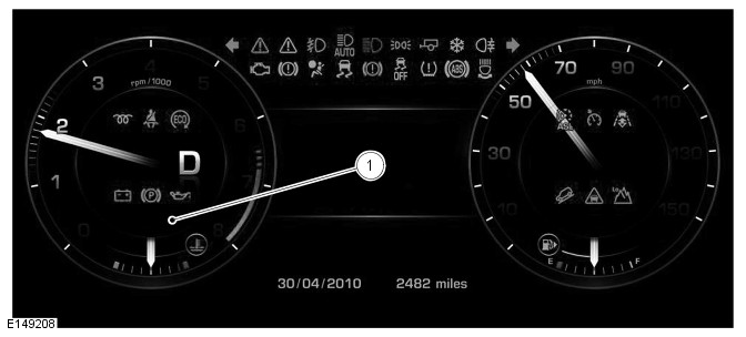
| ITEM | DESCRIPTION |
|---|---|
| 1 | Alarm indicator Light Emitting Diode (LED) |
Operation of the alarm indicator is controlled by the IC which varies the flash rate of the LED to indicate the system status of the alarm and the immobilization systems.
| Alarm/Immobilization Status | Alarm Indicator Status | Alarm Indicator Function |
| UNSET | No flash | LED will flash twice quickly with a long interval between and is repeated 10 times. Slow 'active' flash then follows. |
| SET - with perimeter alarm | Flashing | LED will flash twice quickly with a long interval between and is repeated 10 times. Slow 'active' flash then follows. |
| SET - with volumetric alarm | Flashing | LED will flash three times quickly with a long interval in between and is repeated 10 times. Slow 'active' flash then follows. |
| ACTIVE | Flashing | Slow flash once alarm is activated at a frequency of 100ms on and 200ms off. |
| UNSET - alarm activated during previous SET cycle | Flashing rapidly | LED will flash rapidly until the CJB receives an accessory power mode 4 signal. |
VEHICLE HORNS
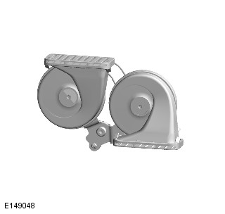
The vehicle horns are located above the front bumper armature. The horns are connected directly to the CJB which activates the horns when the alarm is triggered.
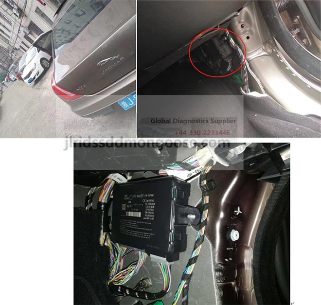
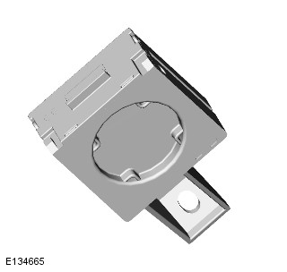
Battery Back-Up Sounder (if fitted)
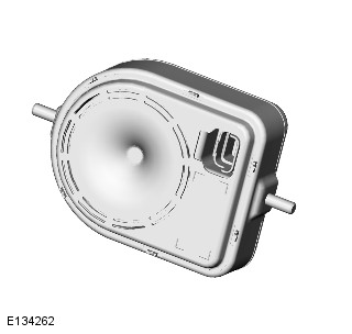
The BBUS is located in the right plenum, in the engine bay. The sounder is only fitted in certain markets.
On vehicles with a BBUS, a tilt sensor is incorporated which monitors the vehicle attitude. The CJB monitors the tilt sensor and can detect if the vehicle is being moved, towed or raised and activate the alarm.
The tilt sensor within the BBUS can be deactivated via the IC options menu to prevent false activations if the vehicle is to be parked on a ferry for example.
Operation of the sounder is controlled by the CJB on a LIN bus. The sounder is also connected with a permanent battery supply via the CJB. An integral, rechargeable battery powers the sounder if the vehicle battery supply from the CJB is interrupted.
Volumetric sensor
The Volumetric sensor is standard fitment in some markets and available as an option in other markets. It is not available in all markets. The Volumetric sensor comprises two sensors which allow the interior of the vehicle to be monitored. The module is located in a central position in the front overhead console.
The Volumetric sensor is activated with the volumetric mode which in turn is enabled when the vehicle is double locked. The vehicle can be locked and alarmed with the module deactivated if a pet is to be left in the vehicle for example, by single locking the active anti-theft system.
When volumetric mode is active, if the vehicle battery voltage falls to below 9 volts, the CJB will ignore any inputs from the module to prevent false alarm activation
| ITEM | DESCRIPTION |
|---|---|
| 1 | Electric Steering Column Lock (ESCL) |
| 2 | Instrument Cluster (IC) |
| 3 | Stop/start switch |
| 4 | LF antenna (5 off) |
| 5 | Radio Frequency (RF) receiver |
| 6 | Keyless Vehicle Module (KVM) |
| 7 | Immobilizer Antenna Unit (IAU) |
Passive Start
The passive start system relies on the detection of a uniquely coded Smartkey via low frequency antennas strategically situated within the vehicle. The antennas ensure the Smartkey is always within the active transmission zone of the antennas wherever the Smartkey is placed inside the vehicle. For this reason the orientation and positioning of the antennas is critical to the correct functioning of the system. The Smartkey also operates the passive entry system. For additional information, refer to: Handles, Locks, Latches and Entry Systems (501-14 Handles, Locks, Latches and Entry Systems, Description and Operation).
The system provides a secure interface between the central junction box (CJB) and the engine control module (ECM) to prevent unauthorized starting of the engine. This is achieved by immobilization of the engine crank system and the fuel system, using encoded data exchange between the Smartkey and multiple control modules.
Engine starting is initiated when the encoded data exchange between the Smartkey and the control modules is verified. The engine management system will then allow engine crank and fueling when an authorization data message is received from the CJB.
The engine can be started by pressing the stop/start switch when 'Park' position is selected and the brake pedal is pressed.
A = Hardwired connection; F = RF Transmission; O = LIN (local interconnect network) bus; D = High speed CAN (controller area network) connection; N = Medium speed CAN bus; W = LF Transmission; AH = Serial Communications Link

| ITEM | DESCRIPTION |
|---|---|
| 1 | Battery Junction Box 2 (BJB2) |
| 2 | Battery Junction Box (BJB) |
| 3 | ESCL |
| 4 | Rear Junction Box (RJB) |
| 5 | IC |
| 6 | Central Junction Box (CJB) |
| 7 | Stop/start switch |
| 8 | IAU |
| 9 | RF receiver |
| 10 | Smartkey |
| 11 | KVM |
| 12 | LF antenna |
| 13 | LF antenna |
| 14 | LF antenna |
| 15 | LF antenna |
| 16 | LF antenna |
| 17 | Battery |
Passive Start
At the request of the CJB the KVM prompts each of the internal low frequency antennas to output a signal. When the Smartkey is in the vehicle cabin, it detects the low frequency signals and responds with a RF radio frequency data-identification signal back to the KVM via the RF receiver.
If the data received matches that stored in the KVM, it continues the passive start process by communicating a 'Smartkey valid’ signal to the CJB via the Medium-speed controller area network (CAN) bus.
Once the CJB receives the authorization and confirms the response with an internal calculation, it passes coded data to the IC on the High-speed CAN bus. Upon confirmation from the IC the ignition is enabled.
Before CJB sends a mobilization signal to the ECM, it will exchange encrypted data with the electric steering lock mechanism to authorize unlocking of the steering column. The IC only provides a ground for the steering lock motor.
Electric Steering Column Lock is market dependent.
The CJB will enable the fuel pump relay which, on diesel vehicles operates the fuel pump and on gasoline vehicles sends a battery voltage supply to the Fuel Pump Driver Module (FPDM) to operate the fuel pump in conjunction with the ECM.
If the KVM fails to locate the Smartkey, a message 'SMARTKEY NOT FOUND REFER TO HANDBOOK' will appear in the IC message center and the keyless start back-up process will have to be used to mobilize and start the vehicle.
Keyless Start Backup
If the vehicle has been unlocked using the emergency key blade or the Smartkey is not detected by the vehicle, it will be necessary to use the keyless start backup to disarm the alarm and start the engine. The following process must be followed in this event:
- Press the stop/start switch, if the KVM fails to locate the Smartkey, the message 'SMARTKEY NOT FOUND REFER TO HANDBOOK' shall be displayed.
- Position the Smartkey against the lower left side of the steering column, with the buttons facing downwards. The ribs denote actual location of the IAU.
- Press the stop/start switch with the brake pedal depressed to start the engine.
If the 'SMARTKEY NOT FOUND WARNING' is no longer displayed (only displayed for 10s), then the sequence would have to be repeated.
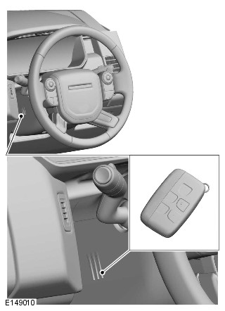
This process bypasses the data exchange between the KVM and the CJB. This is an inductive process and will operate even if the battery in the Smartkey is discharged. A transponder within the Smartkey is detected by the IAU. The IAU communicates this code with the CJB via a local interconnect network (LIN) bus connection. The CJB then initiates the vehicle start process in the normal manner.
The IAU is used if the KVM is unable to authorize the Smartkey. If the KVM is unable to identify the Smartkey, for example if the Smartkey battery voltage is low or there is local RF interference, the transponder within the Smartkey can be read in the conventional manner. The driver will be alerted to this by a chime and a message in the IC message center 'SMARTKEY NOT FOUND REFER TO HANDBOOK'.
Low Frequency (Interior) Antennas
Five LF (low frequency) antennas for the passive start system are positioned in specific locations within the vehicle.
The KVM transmits an LF signal via the antennas which is received by the Smartkey. The Smartkey then responds by transmitting a RF signal which is received by the RF receiver and passed to the KVM for authorization.
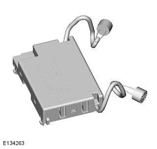
Keyless Vehicle Module
Make sure ALL keys are available and placed on the centre console within the vehicle prior to running the configure new Keyless Vehicle Module (KVM).
The KVM controls signal transmissions to and from the Smartkey and provides authorization to allow the vehicle to be started. The module has a Medium speed CAN connection to the CJB for authorizing vehicle starting.
Radio Frequency Receiver
The RF receiver transmission is received from the Smartkey to enable key identification.