WSM-29758 - Workshop manual Range Rover (LG) 2018 part 2
COMMUNICATIONS NETWORK (G2745075)
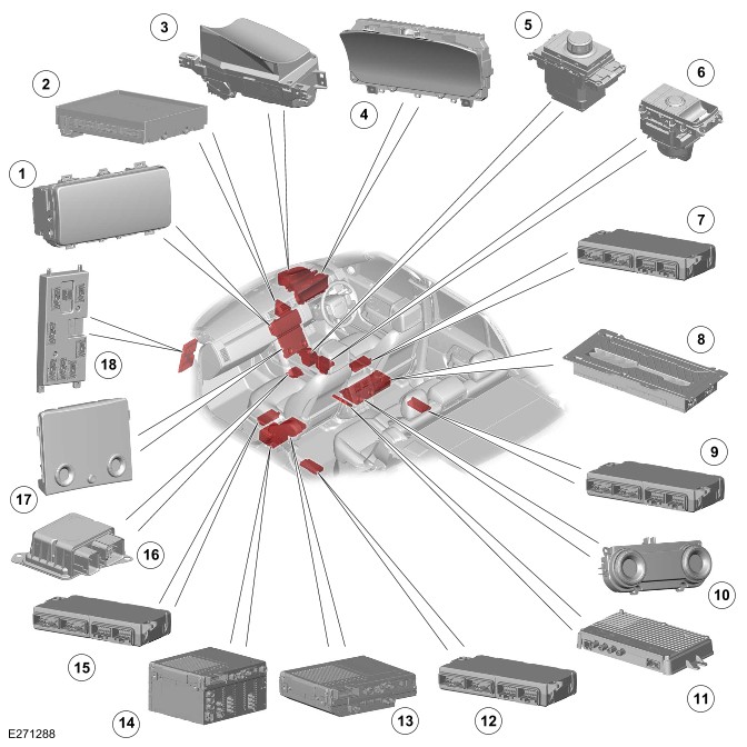
COMPONENT LOCATION - 1 OF 4
Right Hand Drive (RHD) variant shown, Left Hand Drive (LHD) variant is similar.

| ITEM | DESCRIPTION |
|---|---|
| 1 | Anti-lock Brake System (ABS) control module |
| 2 | Electric Steering Column Lock (ESCL) |
| 3 | Steering Wheel Module (SWM) with integrated Steering Angle Sensor Module (SASM) |
| 4 | Image Processing Module 'A' (IPMA) |
| 5 | Transmission Control Module (TCM) |
| 6 | Transfer Case Control Module (TCCM) |
| 7 | Powertrain Control Module (PCM) |
| 8 | Light Emitting Diode Driver Module (LEDDM) - Left |
| 9 | Power Steering Control Module (PSCM) |
| 10 | Adaptive Speed Control Module (ASCM) |
| 11 | Light Emitting Diode Driver Module (LEDDM) - Right |
COMPONENT LOCATION - 2 OF 4
Right Hand Drive (RHD) variant shown, Left Hand Drive (LHD) variant is similar.
| ITEM | DESCRIPTION |
|---|---|
| 1 | Interactive Display Module 'A' (IDMA) |
| 2 | HVAC control module (HVAC) |
| 3 | Head Up Display Control Module (HUDCM) |
| 4 | Instrument Cluster (IC) |
| 5 | Transmission Control Switch (TCS) |
| 6 | Terrain Response (TR) switchpack |
| 7 | Driver Seat Module (DSM) |
| 8 | Audio Amplifier Module (AAM) |
| 9 | Rear Seat Module (RSM) - Right |
| 10 | Rear Integrated Control Panel (RICP) |
| 11 | General Proximity Sensor Module (GPSM) |
| 9 | Rear Seat Module (RSM) - Left |
| 13 | Infotainment Slave Controller (ISC) |
| 14 | Infotainment Master Controller (IMC) |
| 15 | Passenger Seat Module (PSM) |
| 16 | Restraints Control Module (RCM) |
| 17 | Interactive Control Display Module (ICDM) |
| 18 | Body Control Module/Gateway Module (BCM/GWM) |
COMPONENT LOCATION - 3 OF 4
Right Hand Drive (RHD) variant shown, Left Hand Drive (LHD) variant is similar.
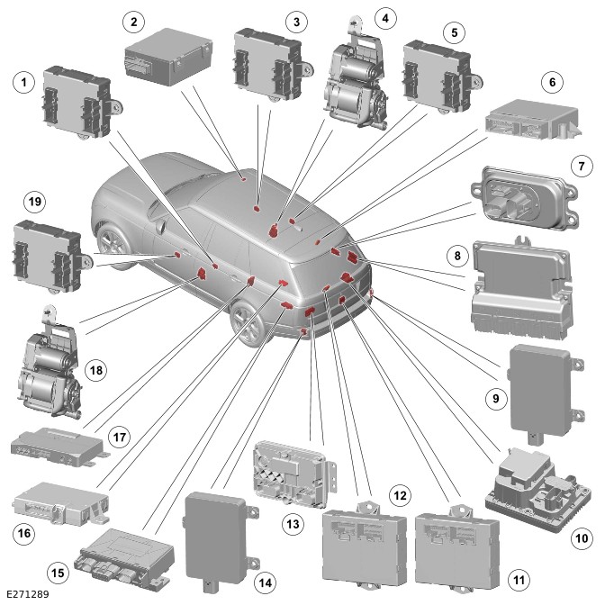
| ITEM | DESCRIPTION |
|---|---|
| 1 | Rear Door Module (RDM) - Left |
| 2 | Tire Pressure Monitoring System (TPMS) control module |
| 3 | Driver Door Module (DDM) |
| 4 | Active seatbelt pretensioner - Right |
| 5 | Rear Door Module (RDM) - Right |
| 6 | Parking Assist Control Module (PACM) |
| 7 | Voltage Quality Module (VQM) |
| 8 | Chassis Control Module (CHCM) |
| 9 | Blind Spot Monitoring Control Module (BMCM) - Right |
| 10 | Power Supply Distribution Box (PSDB) |
| 11 | Tailgate Control Module (TGCM) - Lower |
| 12 | Tailgate Control Module (TGCM) - Upper |
| 13 | Rear Differential Control Module (RDCM) |
| 14 | Blind Spot Monitoring Control Module (BMCM) - Left |
| 15 | Deployable Towbar Control Module (DTCM) |
| 16 | Remote Function Actuator (RFA) |
| 17 | Telematics Control Unit (TCU) |
| 18 | Active seatbelt pretensioner - Left |
| 19 | Passenger Door Module (PDM) |
COMPONENT LOCATION - 4 OF 4 - OCCUPANT CLASSIFICATION SYSTEM - NORTH AMERICAN SPECIFICATION MARKET ONLY

| ITEM | DESCRIPTION |
|---|---|
| 1 | Occupant Classification Sensor Control Module (OCSCM) |
A number of different types of communication network are incorporated into the vehicle wiring harnesses for the transmission of commands and information between control modules. The configuration installed on a particular vehicle depends on the model and equipment level.
The control diagrams shown in this section are schematics reflecting communications networks fitted to Right Hand Drive (RHD) vehicles only. For detailed layouts of the various communications networks fitted to RHD and Left Hand Drive (LHD) vehicles refer to the Electrical Guide.
The communications networks available on the vehicle are shown below:
- Diagnostics over Internet Protocol (DoIP)
- High Speed (HS) Controller Area Network (CAN) diagnostic bus
- FlexRay
- HS CAN chassis systems bus
- HS CAN comfort systems bus
- HS CAN powertrain systems bus
- HS CAN body systems bus
- HS CAN power mode zero systems bus
- Local Interconnect Network (LIN)
- Private CAN bus
- BroadR-Reach® Ethernet
- Automotive Pixel Link 2 (APIX2).
Refer to the relevant system section for details of system description.
DIAGNOSTIC CONNECTOR
The Diagnostic Connector (J1962) is connected to the Body Control Module/Gateway Module (BCM/GWM) through Diagnostic over Internet Protocol (DoIP) and High Speed (HS) Controller Area Network (CAN) diagnostic bus. The DoIP is the prime connection for the Jaguar Land Rover (JLR) approved diagnostic equipment.
Refer to the relevant system section for details of system operation.
CONTROL DIAGRAM - 1 OF 22 - DIAGNOSTIC CONNECTOR
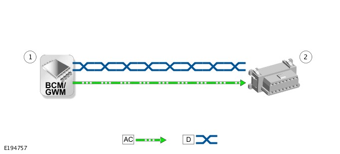
AC = DIAGNOSTICS OVER INTERNET PROTOCOL (DOIP): D = HIGH SPEED (HS) CONTROLLER AREA NETWORK (CAN) DIAGNOSTIC BUS.
| ITEM | DESCRIPTION |
|---|---|
| 1 | Body Control Module/Gateway Module (BCM/GWM) |
| 2 | Diagnostic Connector (J1962) |
CONTROL DIAGRAM - 2 OF 22 - FLEXRAY
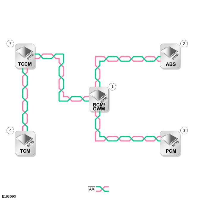
AX = FLEXRAY.
| ITEM | DESCRIPTION |
|---|---|
| 1 | Body Control Module/Gateway Module (BCM/GWM) |
| 2 | Anti-lock Brake System (ABS) control module |
| 3 | Powertrain Control Module (PCM) |
| 4 | Transmission Control Module (TCM) |
| 5 | Transfer Case Control Module (TCCM) |
CONTROL DIAGRAM - 3 OF 22 - HIGH SPEED CONTROLLER AREA NETWORK CHASSIS SYSTEMS BUS
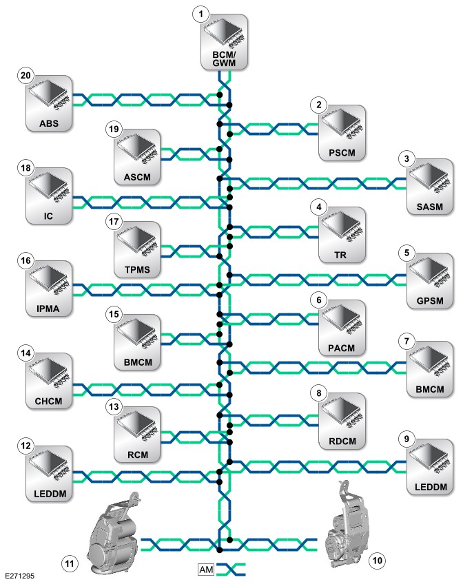
AM = HIGH SPEED (HS) CONTROLLER AREA NETWORK (CAN) CHASSIS SYSTEMS BUS.
| ITEM | DESCRIPTION |
|---|---|
| 1 | Body Control Module/Gateway Module (BCM/GWM) |
| 2 | Power Steering Control Module (PSCM) |
| 3 | Steering Angle Sensor Module (SASM) |
| 4 | Terrain Response (TR) switchpack |
| 5 | General Proximity Sensor Module (GPSM) |
| 6 | Parking Assist Control Module (PACM) |
| 7 | Blind Spot Monitoring Control Module (BMCM) - Right |
| 8 | Rear Differential Control Module (RDCM) |
| 9 | Light Emitting Diode Driver Module (LEDDM) - Right |
| 10 | Active seatbelt pretensioner - Right |
| 11 | Active seatbelt pretensioner - Left |
| 12 | Light Emitting Diode Driver Module (LEDDM) - Left |
| 13 | Restraints Control Module (RCM) |
| 14 | Chassis Control Module (CHCM) |
| 15 | Blind Spot Monitoring Control Module (BMCM) - Left |
| 16 | Image Processing Module 'A' (IPMA) |
| 17 | Tire Pressure Monitoring System (TPMS) |
| 18 | Instrument Cluster (IC) |
| 19 | Adaptive Speed Control Module (ASCM) |
| 20 | Anti-lock Brake System (ABS) control module |
CONTROL DIAGRAM - 4 OF 22 - HIGH SPEED CONTROLLER AREA NETWORK COMFORT SYSTEMS BUS
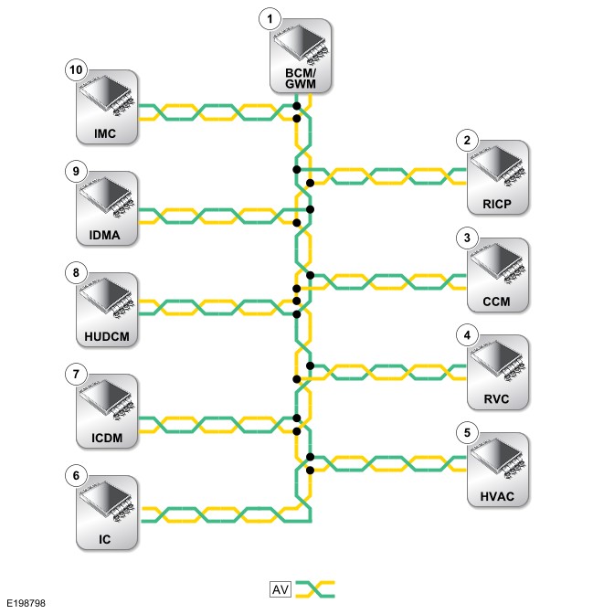
AV = HIGH SPEED (HS) CONTROLLER AREA NETWORK (CAN) COMFORT SYSTEMS BUS.
| ITEM | DESCRIPTION |
|---|---|
| 1 | Body Control Module/Gateway Module (BCM/GWM) |
| 2 | Rear Integrated Control Panel (RICP) |
| 3 | Camera Control Module (CCM) |
| 4 | Rear View Camera (RVC) |
| 5 | HVAC control module (HVAC) |
| 6 | Instrument Cluster (IC) |
| 7 | Interactive Control Display Module (ICDM) |
| 8 | Head Up Display Control Module (HUDCM) |
| 9 | Interactive Display Module 'A' (IDMA) |
| 10 | Infotainment Master Controller (IMC) |
CONTROL DIAGRAM - 5 OF 22 - HIGH SPEED CONTROLLER AREA NETWORK POWERTRAIN SYSTEMS BUS

AN = HIGH SPEED (HS) CONTROLLER AREA NETWORK (CAN) POWERTRAIN SYSTEMS BUS.
| ITEM | DESCRIPTION |
|---|---|
| 1 | Body Control Module/Gateway Module (BCM/GWM) |
| 2 | Transmission Control Switch (TCS) |
| 3 | Transmission Control Module (TCM) |
CONTROL DIAGRAM - 6 OF 22 - HIGH SPEED CONTROLLER AREA NETWORK BODY SYSTEMS BUS
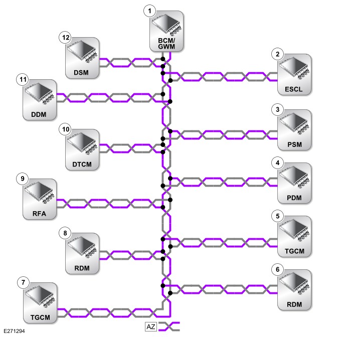
AZ = HIGH SPEED (HS) CONTROLLER AREA NETWORK (CAN) BODY SYSTEMS BUS.
| ITEM | DESCRIPTION |
|---|---|
| 1 | Body Control Module/Gateway Module (BCM/GWM) |
| 2 | Electric Steering Column Lock (ESCL) control module |
| 3 | Passenger Seat Module (PSM) |
| 4 | Passenger Door Module (PDM) |
| 5 | Tailgate Control Module (TGCM) - Upper |
| 6 | Rear Door Module (RDM) - Left |
| 7 | Tailgate Control Module (TGCM) - Lower |
| 8 | Rear Door Module (RDM) - Right |
| 9 | Remote Function Actuator (RFA) |
| 10 | Deployable Towbar Control Module (DTCM) |
| 11 | Driver Door Module (DDM) |
| 12 | Driver Seat Module (DSM) |
CONTROL DIAGRAM - 7 OF 22 - HIGH SPEED CONTROLLER AREA NETWORK POWER MODE ZERO SYSTEMS BUS
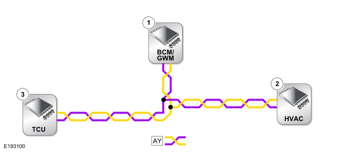
AY = HIGH SPEED (HS) CONTROLLER AREA NETWORK (CAN) POWER MODE ZERO SYSTEMS BUS.
| ITEM | DESCRIPTION |
|---|---|
| 1 | Body Control Module/Gateway Module (BCM/GWM) |
| 2 | HVAC control module (HVAC) |
| 3 | Telematics Control Unit (TCU) |
CONTROL DIAGRAM - 8 OF 22 - LOCAL INTERCONNECT NETWORK - BODY CONTROL MODULE/GATEWAY MODULE
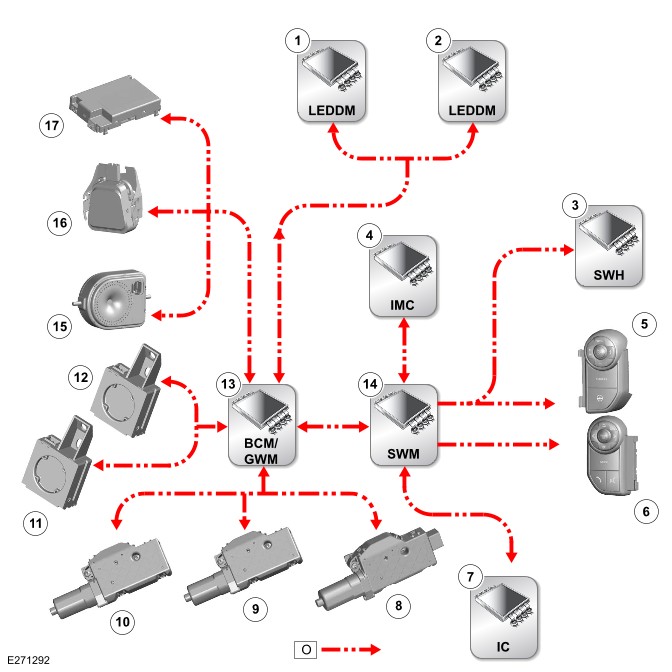
O = LOCAL INTERCONNECT NETWORK (LIN) BUS.
| ITEM | DESCRIPTION |
|---|---|
| 1 | Light Emitting Diode Driver Module (LEDDM) - Left |
| 2 | Light Emitting Diode Driver Module (LEDDM) - Right |
| 3 | Steering Wheel Heater (SWH) control module |
| 4 | Infotainment Master Controller (IMC) |
| 5 | Right steering wheel switchpack |
| 6 | Left steering wheel switchpack |
| 7 | Instrument Cluster (IC) |
| 8 | Roof opening panel motor |
| 9 | Roof opening panel blind motor - Front |
| 10 | Roof opening panel blind motor - Rear |
| 11 | Immobilizer Antenna Unit (IAU) |
| 12 | Activity key transceiver module |
| 13 | Body Control Module/Gateway Module (BCM/GWM) |
| 14 | Steering Wheel Module (SWM) |
| 15 | Battery Back-Up Sounder (BBUS) |
| 16 | Rain/light sensor |
| 17 | Volumetric sensor |
CONTROL DIAGRAM - 9 OF 22 - LOCAL INTERCONNECT NETWORK - OCCUPANT CLASSIFICATION SENSOR CONTROL MODULE - NORTH AMERICAN SPECIFICATION MARKET ONLY

O = LOCAL INTERCONNECT NETWORK (LIN) BUS.
| ITEM | DESCRIPTION |
|---|---|
| 1 | Occupant Classification Sensor Control Module (OCSCM) |
| 2 | Restraints Control Module (RCM) |
CONTROL DIAGRAM - 10 OF 22 - LOCAL INTERCONNECT NETWORK - POWERTRAIN CONTROL MODULE

O = LOCAL INTERCONNECT NETWORK (LIN) BUS.
| ITEM | DESCRIPTION |
|---|---|
| 1 | Powertrain Control Module (PCM) |
| 2 | Active grille air shutter motor |
| 3 | Glow plug control module |
CONTROL DIAGRAM - 11 OF 22 - LOCAL INTERCONNECT NETWORK - BATTERY MONITORING SYSTEM
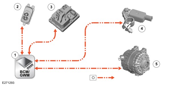
O = LOCAL INTERCONNECT NETWORK (LIN) BUS.
| ITEM | DESCRIPTION |
|---|---|
| 1 | Body Control Module/Gateway Module (BCM/GWM) |
| 2 | Voltage Quality Module (VQM) |
| 3 | Power Supply Distribution Box (PSDB) |
| 4 | Battery Monitoring Sensor (BMS) |
| 5 | Generator |
CONTROL DIAGRAM - 12 OF 22 - LOCAL INTERCONNECT NETWORK - HVAC CONTROL MODULE
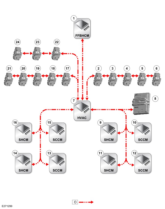
O = LOCAL INTERCONNECT NETWORK (LIN) BUS.
| ITEM | DESCRIPTION |
|---|---|
| 1 | Fuel Fired Booster Heater Control Module (FFBHCM) |
| 2 | Cool air bypass motor |
| 3 | Recirculation motor |
| 4 | Distribution motor - Front right |
| 5 | Temperature blend motor - Front right |
| 6 | Temperature blend motor - Rear right |
| 7 | HVAC control module (HVAC) |
| 8 | Humidity sensor |
| 9 | Seat Heater Control Module (SHCM) - Driver |
| 10 | Seat Climate Control Module (SCCM) - Driver |
| 11 | SHCM - Rear right |
| 12 | SCCM - Rear right |
| 13 | SCCM - Rear left |
| 14 | SHCM - Rear left |
| 15 | SCCM - Passenger |
| 16 | SHCM - Passenger |
| 17 | Distribution motor - Demist |
| 18 | Auxiliary climate control face/feet motor |
| 19 | Temperature blend motor - Rear left |
| 20 | Temperature blend motor - Front left |
| 21 | Distribution motor - Front left |
| 22 | Temperature blend motor - Auxiliary left |
| 23 | Temperature blend motor - Auxiliary right |
| 24 | Distribution motor - Rear |
CONTROL DIAGRAM - 13 OF 22 - LOCAL INTERCONNECT NETWORK - DRIVER DOOR MODULE
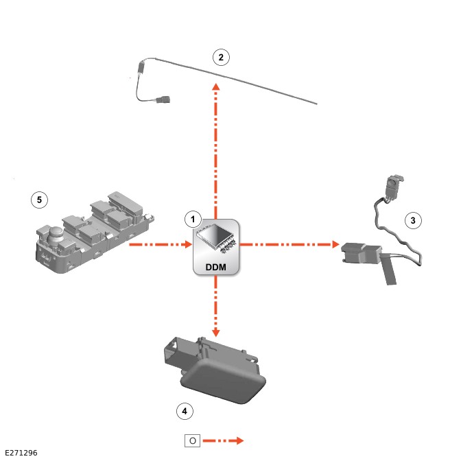
O = LOCAL INTERCONNECT NETWORK (LIN) BUS.
| ITEM | DESCRIPTION |
|---|---|
| 1 | Driver Door Module (DDM) |
| 2 | Light Emitting Diode (LED) - Front door pocket ambience lighting |
| 3 | Light Emitting Diode (LED) - Interior door handle ambience lighting |
| 4 | Light Emitting Diode (LED) - Door puddle lamp ambience lighting |
| 5 | Driver door switchpack |
CONTROL DIAGRAM - 14 OF 22 - LOCAL INTERCONNECT NETWORK - PASSENGER DOOR MODULE
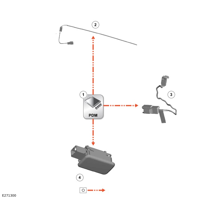
O = LOCAL INTERCONNECT NETWORK (LIN) BUS.
| ITEM | DESCRIPTION |
|---|---|
| 1 | Passenger Door Module (PDM) |
| 2 | Light Emitting Diode (LED) - Front door pocket ambience lighting |
| 3 | Light Emitting Diode (LED) - Interior door handle ambience lighting |
| 4 | Light Emitting Diode (LED) - Door puddle lamp ambience lighting |
CONTROL DIAGRAM - 15 OF 22 - LOCAL INTERCONNECT NETWORK - DRIVER SEAT MODULE
Right Hand Drive (RHD) variant shown, Left Hand Drive (LHD) variant is similar.
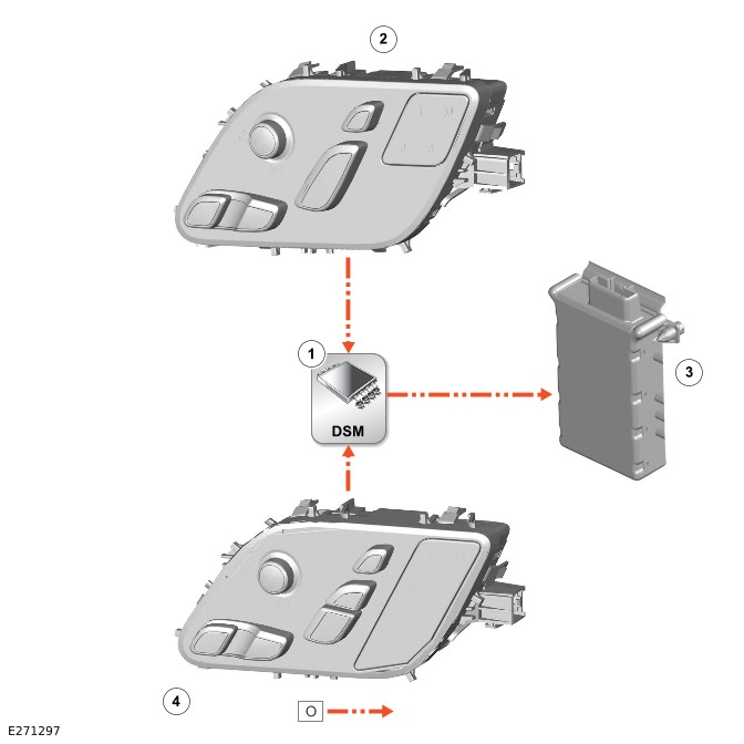
O = LOCAL INTERCONNECT NETWORK (LIN) BUS.
| ITEM | DESCRIPTION |
|---|---|
| 1 | Driver Seat Module (DSM) |
| 2 | Driver seat switchpack |
| 3 | Massage solenoid |
| 4 | Seat switchpack - Rear right |
CONTROL DIAGRAM - 16 OF 22 - LOCAL INTERCONNECT NETWORK - PASSENGER SEAT MODULE
Right Hand Drive (RHD) variant shown, Left Hand Drive (LHD) variant is similar.

O = LOCAL INTERCONNECT NETWORK (LIN) BUS.
| ITEM | DESCRIPTION |
|---|---|
| 1 | Passenger Seat Module (PSM) |
| 2 | Passenger seat switchpack |
| 3 | Massage solenoid |
| 4 | Seat switchpack - Rear left |
CONTROL DIAGRAM - 17 OF 22 - LOCAL INTERCONNECT NETWORK - REMOTE FUNCTION ACTUATOR
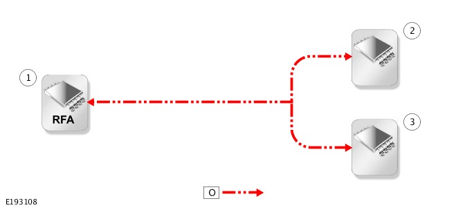
O = LOCAL INTERCONNECT NETWORK (LIN) BUS.
| ITEM | DESCRIPTION |
|---|---|
| 1 | Remote Function Actuator (RFA) |
| 2 | Hands-free tailgate module - Left |
| 3 | Hands-free tailgate module - Right |
CONTROL DIAGRAM - 18 OF 22 - PRIVATE CONTROLLER AREA NETWORK BUS - BLIND SPOT MONITORING CONTROL MODULE
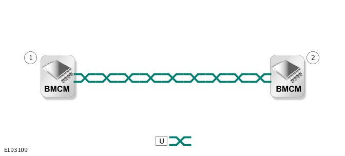
U = PRIVATE CONTROLLER AREA NETWORK (CAN) BUS.
| ITEM | DESCRIPTION |
|---|---|
| 1 | Blind Spot Monitoring Control Module (BMCM) - Left |
| 2 | Blind Spot Monitoring Control Module (BMCM) - Right |
CONTROL DIAGRAM - 19 OF 22 - PRIVATE CONTROLLER AREA NETWORK BUS - LIGHT EMITTING DIODE DRIVER MODULE
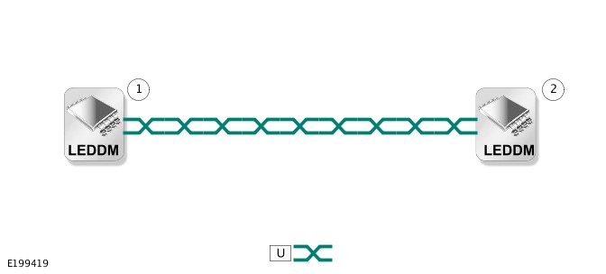
U = PRIVATE CONTROLLER AREA NETWORK (CAN) BUS.
| ITEM | DESCRIPTION |
|---|---|
| 1 | Light Emitting Diode Driver Module (LEDDM) - Left |
| 2 | Light Emitting Diode Driver Module (LEDDM) - Right |
CONTROL DIAGRAM - 20 OF 22 - PRIVATE CONTROLLER AREA NETWORK BUS - ADAPTIVE SPEED CONTROL
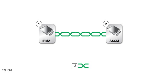
U = PRIVATE CONTROLLER AREA NETWORK (CAN) BUS.
| ITEM | DESCRIPTION |
|---|---|
| 1 | Image Processing Module 'A' (IPMA) |
| 2 | Adaptive Speed Control Module (ASCM) |
CONTROL DIAGRAM - 21 OF 22 - BROADR-REACH® ETHERNET
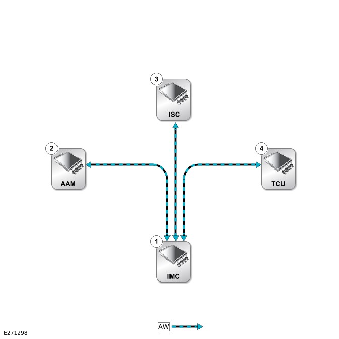
AW = BROADR-REACH® ETHERNET.
| ITEM | DESCRIPTION |
|---|---|
| 1 | Infotainment Master Controller (IMC) |
| 2 | Audio Amplifier Module (AAM) |
| 3 | Infotainment Slave Controller (ISC) |
| 4 | Telematics Control Unit (TCU) |
CONTROL DIAGRAM - 22 OF 22 - AUTOMOTIVE PIXEL LINK 2
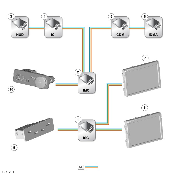
AU = AUTOMOTIVE PIXEL LINK 2 (APIX2).
| ITEM | DESCRIPTION |
|---|---|
| 1 | Infotainment Slave Controller (ISC) |
| 2 | Infotainment Master Controller (IMC) |
| 3 | Head Up Display (HUD) |
| 4 | Instrument Cluster (IC) |
| 5 | Interactive Control Display Module (ICDM) |
| 6 | Interactive Display Module 'A' (IDMA) |
| 7 | Rear Seat Entertainment (RSE) screen - Left |
| 8 | Rear Seat Entertainment (RSE) screen - Right |
| 9 | Rear portable media interface panel |
| 10 | Front portable media interface panel |
MULTIFUNCTION ELECTRONIC MODULES
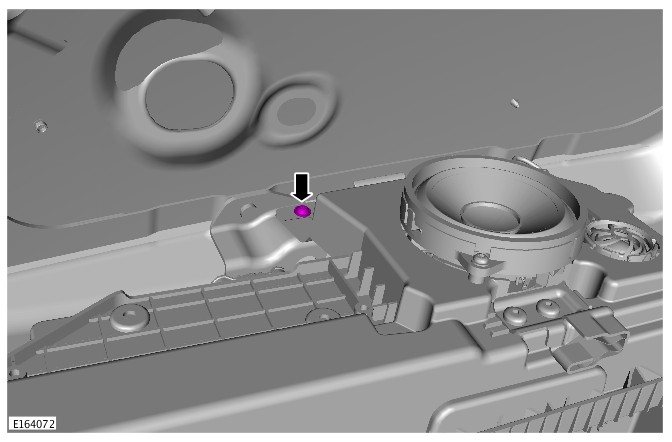
KEYLESS VEHICLE MODULE (G1561113)
- 86.80.08
- REMOTE FUNCTION ACTUATOR (RFA) - RENEW
- ALL DERIVATIVES
- 0.70
- USED WITHINS
-
This procedure contains some variation in the illustrations depending on the vehicle specification, but the essential information is always correct.
-
This procedure contains illustrations showing certain components removed to provide extra clarity.
- Remove the LH upper trim panel.
Refer to: Luggage Compartment Upper Trim Panel (501-05 Interior Trim and Ornamentation, Removal and Installation).
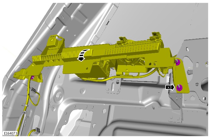

- To install, reverse the removal procedure.
- If a new component has been installed, configure using Land Rover approved diagnostic equipment.
-
MODULE COMMUNICATIONS NETWORK
COMMUNICATIONS NETWORK (G2745075)
DESCRIPTION AND OPERATIONCOMPONENT LOCATIONCOMPONENT LOCATION - 1 OF 4
NOTE:Right Hand Drive (RHD) variant shown, Left Hand Drive (LHD) variant is similar.
ITEM DESCRIPTION 1 Anti-lock Brake System (ABS) control module 2 Electric Steering Column Lock (ESCL) 3 Steering Wheel Module (SWM) with integrated Steering Angle Sensor Module (SASM) 4 Image Processing Module 'A' (IPMA) 5 Transmission Control Module (TCM) 6 Transfer Case Control Module (TCCM) 7 Powertrain Control Module (PCM) 8 Light Emitting Diode Driver Module (LEDDM) - Left 9 Power Steering Control Module (PSCM) 10 Adaptive Speed Control Module (ASCM) 11 Light Emitting Diode Driver Module (LEDDM) - Right COMPONENT LOCATION - 2 OF 4
NOTE:Right Hand Drive (RHD) variant shown, Left Hand Drive (LHD) variant is similar.
ITEM DESCRIPTION 1 Interactive Display Module 'A' (IDMA) 2 HVAC control module (HVAC) 3 Head Up Display Control Module (HUDCM) 4 Instrument Cluster (IC) 5 Transmission Control Switch (TCS) 6 Terrain Response (TR) switchpack 7 Driver Seat Module (DSM) 8 Audio Amplifier Module (AAM) 9 Rear Seat Module (RSM) - Right 10 Rear Integrated Control Panel (RICP) 11 General Proximity Sensor Module (GPSM) 9 Rear Seat Module (RSM) - Left 13 Infotainment Slave Controller (ISC) 14 Infotainment Master Controller (IMC) 15 Passenger Seat Module (PSM) 16 Restraints Control Module (RCM) 17 Interactive Control Display Module (ICDM) 18 Body Control Module/Gateway Module (BCM/GWM) COMPONENT LOCATION - 3 OF 4
NOTE:Right Hand Drive (RHD) variant shown, Left Hand Drive (LHD) variant is similar.
ITEM DESCRIPTION 1 Rear Door Module (RDM) - Left 2 Tire Pressure Monitoring System (TPMS) control module 3 Driver Door Module (DDM) 4 Active seatbelt pretensioner - Right 5 Rear Door Module (RDM) - Right 6 Parking Assist Control Module (PACM) 7 Voltage Quality Module (VQM) 8 Chassis Control Module (CHCM) 9 Blind Spot Monitoring Control Module (BMCM) - Right 10 Power Supply Distribution Box (PSDB) 11 Tailgate Control Module (TGCM) - Lower 12 Tailgate Control Module (TGCM) - Upper 13 Rear Differential Control Module (RDCM) 14 Blind Spot Monitoring Control Module (BMCM) - Left 15 Deployable Towbar Control Module (DTCM) 16 Remote Function Actuator (RFA) 17 Telematics Control Unit (TCU) 18 Active seatbelt pretensioner - Left 19 Passenger Door Module (PDM) COMPONENT LOCATION - 4 OF 4 - OCCUPANT CLASSIFICATION SYSTEM - NORTH AMERICAN SPECIFICATION MARKET ONLY
ITEM DESCRIPTION 1 Occupant Classification Sensor Control Module (OCSCM) OVERVIEWA number of different types of communication network are incorporated into the vehicle wiring harnesses for the transmission of commands and information between control modules. The configuration installed on a particular vehicle depends on the model and equipment level.
NOTE:The control diagrams shown in this section are schematics reflecting communications networks fitted to Right Hand Drive (RHD) vehicles only. For detailed layouts of the various communications networks fitted to RHD and Left Hand Drive (LHD) vehicles refer to the Electrical Guide.
The communications networks available on the vehicle are shown below:
- Diagnostics over Internet Protocol (DoIP)
- High Speed (HS) Controller Area Network (CAN) diagnostic bus
- FlexRay
- HS CAN chassis systems bus
- HS CAN comfort systems bus
- HS CAN powertrain systems bus
- HS CAN body systems bus
- HS CAN power mode zero systems bus
- Local Interconnect Network (LIN)
- Private CAN bus
- BroadR-Reach® Ethernet
- Automotive Pixel Link 2 (APIX2).
DESCRIPTIONRefer to the relevant system section for details of system description.
DIAGNOSTIC CONNECTOR
The Diagnostic Connector (J1962) is connected to the Body Control Module/Gateway Module (BCM/GWM) through Diagnostic over Internet Protocol (DoIP) and High Speed (HS) Controller Area Network (CAN) diagnostic bus. The DoIP is the prime connection for the Jaguar Land Rover (JLR) approved diagnostic equipment.
OPERATIONRefer to the relevant system section for details of system operation.
CONTROL DIAGRAMCONTROL DIAGRAM - 1 OF 22 - DIAGNOSTIC CONNECTOR
AC = DIAGNOSTICS OVER INTERNET PROTOCOL (DOIP): D = HIGH SPEED (HS) CONTROLLER AREA NETWORK (CAN) DIAGNOSTIC BUS.
ITEM DESCRIPTION 1 Body Control Module/Gateway Module (BCM/GWM) 2 Diagnostic Connector (J1962) CONTROL DIAGRAM - 2 OF 22 - FLEXRAY
AX = FLEXRAY.
ITEM DESCRIPTION 1 Body Control Module/Gateway Module (BCM/GWM) 2 Anti-lock Brake System (ABS) control module 3 Powertrain Control Module (PCM) 4 Transmission Control Module (TCM) 5 Transfer Case Control Module (TCCM) CONTROL DIAGRAM - 3 OF 22 - HIGH SPEED CONTROLLER AREA NETWORK CHASSIS SYSTEMS BUS
AM = HIGH SPEED (HS) CONTROLLER AREA NETWORK (CAN) CHASSIS SYSTEMS BUS.
ITEM DESCRIPTION 1 Body Control Module/Gateway Module (BCM/GWM) 2 Power Steering Control Module (PSCM) 3 Steering Angle Sensor Module (SASM) 4 Terrain Response (TR) switchpack 5 General Proximity Sensor Module (GPSM) 6 Parking Assist Control Module (PACM) 7 Blind Spot Monitoring Control Module (BMCM) - Right 8 Rear Differential Control Module (RDCM) 9 Light Emitting Diode Driver Module (LEDDM) - Right 10 Active seatbelt pretensioner - Right 11 Active seatbelt pretensioner - Left 12 Light Emitting Diode Driver Module (LEDDM) - Left 13 Restraints Control Module (RCM) 14 Chassis Control Module (CHCM) 15 Blind Spot Monitoring Control Module (BMCM) - Left 16 Image Processing Module 'A' (IPMA) 17 Tire Pressure Monitoring System (TPMS) 18 Instrument Cluster (IC) 19 Adaptive Speed Control Module (ASCM) 20 Anti-lock Brake System (ABS) control module CONTROL DIAGRAM - 4 OF 22 - HIGH SPEED CONTROLLER AREA NETWORK COMFORT SYSTEMS BUS
AV = HIGH SPEED (HS) CONTROLLER AREA NETWORK (CAN) COMFORT SYSTEMS BUS.
ITEM DESCRIPTION 1 Body Control Module/Gateway Module (BCM/GWM) 2 Rear Integrated Control Panel (RICP) 3 Camera Control Module (CCM) 4 Rear View Camera (RVC) 5 HVAC control module (HVAC) 6 Instrument Cluster (IC) 7 Interactive Control Display Module (ICDM) 8 Head Up Display Control Module (HUDCM) 9 Interactive Display Module 'A' (IDMA) 10 Infotainment Master Controller (IMC) CONTROL DIAGRAM - 5 OF 22 - HIGH SPEED CONTROLLER AREA NETWORK POWERTRAIN SYSTEMS BUS
AN = HIGH SPEED (HS) CONTROLLER AREA NETWORK (CAN) POWERTRAIN SYSTEMS BUS.
ITEM DESCRIPTION 1 Body Control Module/Gateway Module (BCM/GWM) 2 Transmission Control Switch (TCS) 3 Transmission Control Module (TCM) CONTROL DIAGRAM - 6 OF 22 - HIGH SPEED CONTROLLER AREA NETWORK BODY SYSTEMS BUS
AZ = HIGH SPEED (HS) CONTROLLER AREA NETWORK (CAN) BODY SYSTEMS BUS.
ITEM DESCRIPTION 1 Body Control Module/Gateway Module (BCM/GWM) 2 Electric Steering Column Lock (ESCL) control module 3 Passenger Seat Module (PSM) 4 Passenger Door Module (PDM) 5 Tailgate Control Module (TGCM) - Upper 6 Rear Door Module (RDM) - Left 7 Tailgate Control Module (TGCM) - Lower 8 Rear Door Module (RDM) - Right 9 Remote Function Actuator (RFA) 10 Deployable Towbar Control Module (DTCM) 11 Driver Door Module (DDM) 12 Driver Seat Module (DSM) CONTROL DIAGRAM - 7 OF 22 - HIGH SPEED CONTROLLER AREA NETWORK POWER MODE ZERO SYSTEMS BUS
AY = HIGH SPEED (HS) CONTROLLER AREA NETWORK (CAN) POWER MODE ZERO SYSTEMS BUS.
ITEM DESCRIPTION 1 Body Control Module/Gateway Module (BCM/GWM) 2 HVAC control module (HVAC) 3 Telematics Control Unit (TCU) CONTROL DIAGRAM - 8 OF 22 - LOCAL INTERCONNECT NETWORK - BODY CONTROL MODULE/GATEWAY MODULE
O = LOCAL INTERCONNECT NETWORK (LIN) BUS.
ITEM DESCRIPTION 1 Light Emitting Diode Driver Module (LEDDM) - Left 2 Light Emitting Diode Driver Module (LEDDM) - Right 3 Steering Wheel Heater (SWH) control module 4 Infotainment Master Controller (IMC) 5 Right steering wheel switchpack 6 Left steering wheel switchpack 7 Instrument Cluster (IC) 8 Roof opening panel motor 9 Roof opening panel blind motor - Front 10 Roof opening panel blind motor - Rear 11 Immobilizer Antenna Unit (IAU) 12 Activity key transceiver module 13 Body Control Module/Gateway Module (BCM/GWM) 14 Steering Wheel Module (SWM) 15 Battery Back-Up Sounder (BBUS) 16 Rain/light sensor 17 Volumetric sensor CONTROL DIAGRAM - 9 OF 22 - LOCAL INTERCONNECT NETWORK - OCCUPANT CLASSIFICATION SENSOR CONTROL MODULE - NORTH AMERICAN SPECIFICATION MARKET ONLY
O = LOCAL INTERCONNECT NETWORK (LIN) BUS.
ITEM DESCRIPTION 1 Occupant Classification Sensor Control Module (OCSCM) 2 Restraints Control Module (RCM) CONTROL DIAGRAM - 10 OF 22 - LOCAL INTERCONNECT NETWORK - POWERTRAIN CONTROL MODULE
O = LOCAL INTERCONNECT NETWORK (LIN) BUS.
ITEM DESCRIPTION 1 Powertrain Control Module (PCM) 2 Active grille air shutter motor 3 Glow plug control module CONTROL DIAGRAM - 11 OF 22 - LOCAL INTERCONNECT NETWORK - BATTERY MONITORING SYSTEM
O = LOCAL INTERCONNECT NETWORK (LIN) BUS.
ITEM DESCRIPTION 1 Body Control Module/Gateway Module (BCM/GWM) 2 Voltage Quality Module (VQM) 3 Power Supply Distribution Box (PSDB) 4 Battery Monitoring Sensor (BMS) 5 Generator CONTROL DIAGRAM - 12 OF 22 - LOCAL INTERCONNECT NETWORK - HVAC CONTROL MODULE
O = LOCAL INTERCONNECT NETWORK (LIN) BUS.
ITEM DESCRIPTION 1 Fuel Fired Booster Heater Control Module (FFBHCM) 2 Cool air bypass motor 3 Recirculation motor 4 Distribution motor - Front right 5 Temperature blend motor - Front right 6 Temperature blend motor - Rear right 7 HVAC control module (HVAC) 8 Humidity sensor 9 Seat Heater Control Module (SHCM) - Driver 10 Seat Climate Control Module (SCCM) - Driver 11 SHCM - Rear right 12 SCCM - Rear right 13 SCCM - Rear left 14 SHCM - Rear left 15 SCCM - Passenger 16 SHCM - Passenger 17 Distribution motor - Demist 18 Auxiliary climate control face/feet motor 19 Temperature blend motor - Rear left 20 Temperature blend motor - Front left 21 Distribution motor - Front left 22 Temperature blend motor - Auxiliary left 23 Temperature blend motor - Auxiliary right 24 Distribution motor - Rear CONTROL DIAGRAM - 13 OF 22 - LOCAL INTERCONNECT NETWORK - DRIVER DOOR MODULE
O = LOCAL INTERCONNECT NETWORK (LIN) BUS.
ITEM DESCRIPTION 1 Driver Door Module (DDM) 2 Light Emitting Diode (LED) - Front door pocket ambience lighting 3 Light Emitting Diode (LED) - Interior door handle ambience lighting 4 Light Emitting Diode (LED) - Door puddle lamp ambience lighting 5 Driver door switchpack CONTROL DIAGRAM - 14 OF 22 - LOCAL INTERCONNECT NETWORK - PASSENGER DOOR MODULE
O = LOCAL INTERCONNECT NETWORK (LIN) BUS.
ITEM DESCRIPTION 1 Passenger Door Module (PDM) 2 Light Emitting Diode (LED) - Front door pocket ambience lighting 3 Light Emitting Diode (LED) - Interior door handle ambience lighting 4 Light Emitting Diode (LED) - Door puddle lamp ambience lighting CONTROL DIAGRAM - 15 OF 22 - LOCAL INTERCONNECT NETWORK - DRIVER SEAT MODULE
NOTE:Right Hand Drive (RHD) variant shown, Left Hand Drive (LHD) variant is similar.
O = LOCAL INTERCONNECT NETWORK (LIN) BUS.
ITEM DESCRIPTION 1 Driver Seat Module (DSM) 2 Driver seat switchpack 3 Massage solenoid 4 Seat switchpack - Rear right CONTROL DIAGRAM - 16 OF 22 - LOCAL INTERCONNECT NETWORK - PASSENGER SEAT MODULE
NOTE:Right Hand Drive (RHD) variant shown, Left Hand Drive (LHD) variant is similar.
O = LOCAL INTERCONNECT NETWORK (LIN) BUS.
ITEM DESCRIPTION 1 Passenger Seat Module (PSM) 2 Passenger seat switchpack 3 Massage solenoid 4 Seat switchpack - Rear left CONTROL DIAGRAM - 17 OF 22 - LOCAL INTERCONNECT NETWORK - REMOTE FUNCTION ACTUATOR
O = LOCAL INTERCONNECT NETWORK (LIN) BUS.
ITEM DESCRIPTION 1 Remote Function Actuator (RFA) 2 Hands-free tailgate module - Left 3 Hands-free tailgate module - Right CONTROL DIAGRAM - 18 OF 22 - PRIVATE CONTROLLER AREA NETWORK BUS - BLIND SPOT MONITORING CONTROL MODULE
U = PRIVATE CONTROLLER AREA NETWORK (CAN) BUS.
ITEM DESCRIPTION 1 Blind Spot Monitoring Control Module (BMCM) - Left 2 Blind Spot Monitoring Control Module (BMCM) - Right CONTROL DIAGRAM - 19 OF 22 - PRIVATE CONTROLLER AREA NETWORK BUS - LIGHT EMITTING DIODE DRIVER MODULE
U = PRIVATE CONTROLLER AREA NETWORK (CAN) BUS.
ITEM DESCRIPTION 1 Light Emitting Diode Driver Module (LEDDM) - Left 2 Light Emitting Diode Driver Module (LEDDM) - Right CONTROL DIAGRAM - 20 OF 22 - PRIVATE CONTROLLER AREA NETWORK BUS - ADAPTIVE SPEED CONTROL
U = PRIVATE CONTROLLER AREA NETWORK (CAN) BUS.
ITEM DESCRIPTION 1 Image Processing Module 'A' (IPMA) 2 Adaptive Speed Control Module (ASCM) CONTROL DIAGRAM - 21 OF 22 - BROADR-REACH® ETHERNET
AW = BROADR-REACH® ETHERNET.
ITEM DESCRIPTION 1 Infotainment Master Controller (IMC) 2 Audio Amplifier Module (AAM) 3 Infotainment Slave Controller (ISC) 4 Telematics Control Unit (TCU) CONTROL DIAGRAM - 22 OF 22 - AUTOMOTIVE PIXEL LINK 2
AU = AUTOMOTIVE PIXEL LINK 2 (APIX2).
ITEM DESCRIPTION 1 Infotainment Slave Controller (ISC) 2 Infotainment Master Controller (IMC) 3 Head Up Display (HUD) 4 Instrument Cluster (IC) 5 Interactive Control Display Module (ICDM) 6 Interactive Display Module 'A' (IDMA) 7 Rear Seat Entertainment (RSE) screen - Left 8 Rear Seat Entertainment (RSE) screen - Right 9 Rear portable media interface panel 10 Front portable media interface panel