WSM-28116 - Workshop manual F-PACE (X761) 2018
MODULE COMMUNICATIONS NETWORK
COMMUNICATIONS NETWORK (G1921200)
DESCRIPTION AND OPERATION
OVERVIEW
A number of different types of communication networks are incorporated into the vehicle wiring harnesses for the transmission of commands and information between control modules. The configuration installed on a particular vehicle depends on the model and equipment level.
NOTE:
The control diagrams shown in this section are schematics reflecting communications networks fitted to Right Hand Drive (RHD) vehicles only. For detailed layouts of the various communications networks fitted to Right Hand Drive (RHD) and Left Hand Drive (LHD) vehicles refer to the Electrical Guide.
Local Interconnect Network Bus
The Local Interconnect Network (LIN) bus is a low speed broadcast network that employs master and slave components. The master component transmits a message along a single wire to the slave components identifying which slave is to respond. The message has a header (slave identifier) and an empty data field. The identified slave component fills the data field with the relevant information and returns a message to the master component along the same wire.
Controller Area Network Bus
The Controller Area Network (CAN) bus is a high speed broadcast network where control modules automatically transmit information every few milliseconds. Information is broadcast down a pair of twisted wires, known as 'CAN high' and 'CAN low'. Information is transmitted on the CAN bus as a voltage difference between the 2 wires.
Flexray Bus
The FlexRay system connects modules using a similar system to CANbus. Information is broadcast down a pair of twisted wires known as 'Bus Plus (BP)' and 'Bus Minus (BM)'. Information is transmitted on the CAN bus as a voltage difference between the 2 wires. This eliminates the problem of induced voltages in the wires from other electrical devices. FlexRay consists of an Active Star hosted in the Body Control Module/Gateway Module (BCM/GWM)with up to 8 branches. Modules are connected to the branches as either pass-through or terminating nodes. FlexRay is deterministic and requires synchronisation to function.
Private Bus
The Private Bus networks are a local bus for a system, either connecting 2 modules, or a small number of modules. Information is broadcast down a pair of twisted wires, known as 'CAN high' and 'CAN low'. Information is transmitted on the CAN bus as a voltage difference between the 2 wires.
The communications networks available on the vehicle are shown below:
- High Speed (HS) Controller Area Network (CAN) chassis systems bus
- HS CAN body systems bus
- HS CAN Human Machine Interface (HMI) systems bus
- HS CAN power mode zero systems bus
- HS CAN powertrain systems bus
- Flexray bus
- Local Interconnect Network (LIN)
- Private CAN Bus
DESCRIPTION
Refer to the relevant system section for details of system description.
OPERATION
Refer to the relevant system section for details of system operation.
CONTROL DIAGRAMS
HIGH SPEED CONTROLLER AREA NETWORK CHASSIS SYSTEMS BUS
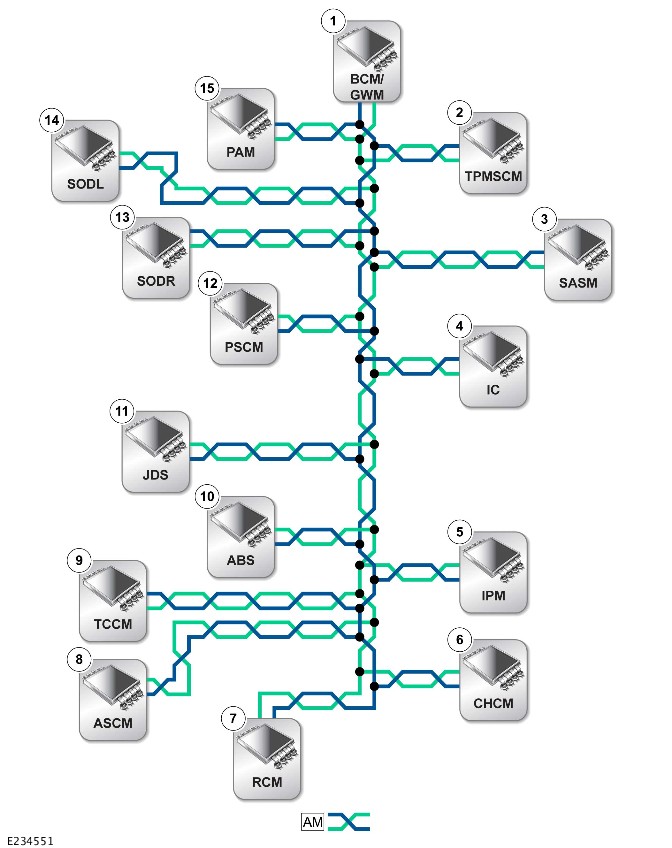
AM = HIGH SPEED (HS) CONTROLLER AREA NETWORK (CAN) CHASSIS SYSTEMS BUS.
| ITEM | DESCRIPTION |
|---|---|
| 1 | Body Control Module/Gateway Module Assembly (BCM/GWM) |
| 2 | Tire Pressure Monitoring System Control Module (TPMSCM) |
| 3 | Steering Angle Sensor Module (SASM) |
| 4 | Instrument Cluster (IC) Diagnostic connector (J1962) |
| 5 | Image Processing Module (IPM) |
| 6 | Chassis Control Module (CHCM) |
| 7 | Restraints Control Module (RCM) |
| 8 | Adaptive Speed Control Module (ASCM) |
| 9 | Transfer Case control Module (TCCM) |
| 10 | Anti-lock Brake System control module (ABS) |
| 11 | JaguarDrive Switchpack (JDS) |
| 12 | Power Steering Control Module (PSCM) |
| 13 | Side Object Detection Control Module – Right (SODR) |
| 14 | Side Object Detection Control Module – Left (SODL) |
| 15 | Parking Assist Control Module (PAM) |
HIGH SPEED CONTROLLER AREA NETWORK BODY SYSTEMS BUS

AZ = HIGH SPEED (HS) CONTROLLER AREA NETWORK (CAN) BODY SYSTEMS BUS.
| ITEM | DESCRIPTION |
|---|---|
| 1 | Body Control Module/Gateway Module (BCM/GWM) |
| 2 | Deployable Towbar Control Module (DTCM) |
| 3 | Remote Function Actuator (RFA) |
| 4 | Rear Door Module (RDM) - Left |
| 5 | Tailgate Control Module (TGCM) |
| 6 | Electric Steering Lock (ESCL) |
| 7 | Passenger Seat Module (PSM) |
| 8 | Driver Door Module (DDM) |
| 9 | Passenger Door Module (PDM) |
| 10 | Driver Seat Module (DSM) |
| 11 | Rear Door Module (RDM) - Right |
HIGH SPEED CONTROLLER AREA NETWORK HUMAN MACHINE INTERFACE SYSTEMS BUS
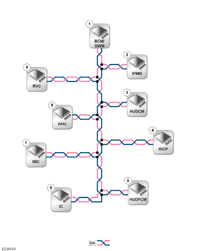
BA = HIGH SPEED (HS) CONTROLLER AREA NETWORK (CAN) HUMAN MACHINE INTERFACE SYSTEMS BUS.
| ITEM | DESCRIPTION |
|---|---|
| 1 | Body Control Module/Gateway Module (BCM/GWM) |
| 2 | Image Processing Module 'B' (IPMB) |
| 3 | Head Up Display Control Module (HUDCM) |
| 4 | Rear Integrated Control Panel (RICP) |
| 5 | Head Up Display Cooling Fan Control Module (HUDCFCM) |
| 6 | Instrument Cluster (IC) |
| 7 | Infotainment Master Controller (IMC) |
| 8 | Audio Head Unit (AHU) |
| 9 | Rear View Camera (RVC) |
HIGH SPEED CONTROLLER AREA NETWORK POWER MODE ZERO SYSTEMS BUS
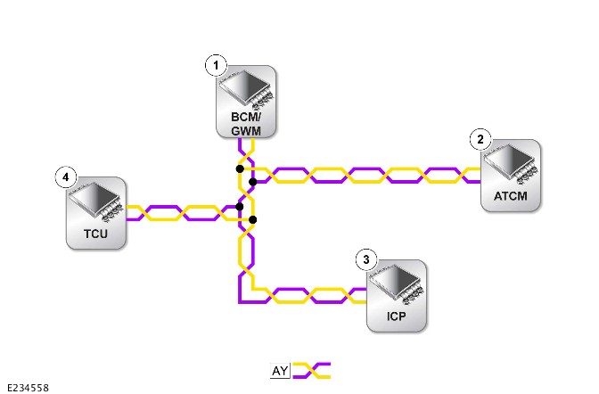
AY = HIGH SPEED (HS) CONTROLLER AREA NETWORK (CAN) POWER MODE ZERO SYSTEMS BUS.
| ITEM | DESCRIPTION |
|---|---|
| 1 | Body Control Module/Gateway Module (BCM/GWM) |
| 2 | HVAC Control Module |
| 3 | Integrated Control Panel (ICP) |
| 4 | Telematics Control Module (TCU) |
HIGH SPEED CONTROLLER AREA NETWORK POWERTRAIN SYSTEMS BUS

AN = HIGH SPEED (HS) CONTROLLER AREA NETWORK (CAN) POWERTRAIN SYSTEMS BUS.
| ITEM | DESCRIPTION |
|---|---|
| 1 | Body Control Module/Gateway Module (BCM/GWM) |
| 2 | Transmission Control Switch (TCS) |
| 3 | Transmission Control Module (TCM) |
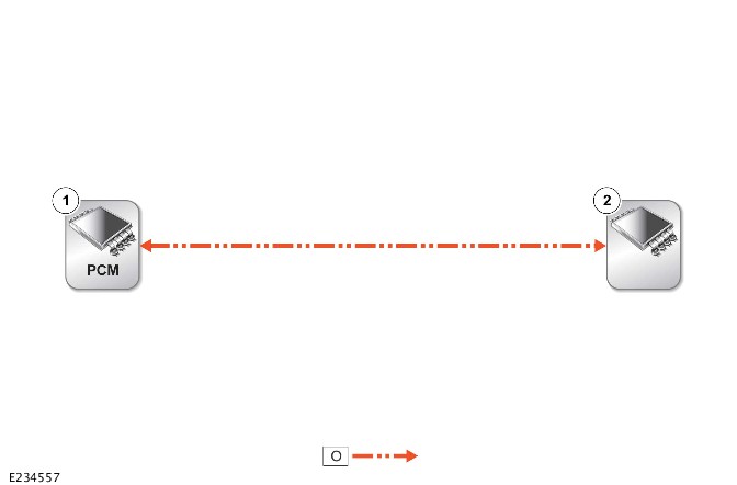
FLEXRAY BUS
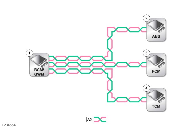
AX = FLEXRAY BUS.
| ITEM | DESCRIPTION |
|---|---|
| 1 | Body Control Module/ Gateway Module (BCM/GWM) |
| 2 | Anti-lock Brake System (ABS) control module |
| 3 | Powertrain Control Module (PCM) |
| 4 | Transmission Control Module (TCM) |
LOCAL INTERCONNECT NETWORK 1 - CLIMATE CONTROL
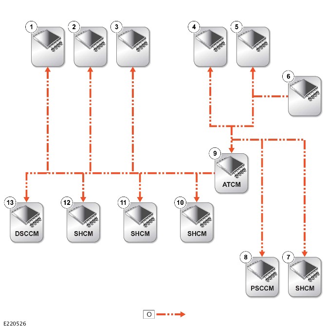
O = LOCAL INTERCONNECT NETWORK (LIN) BUS.
| ITEM | DESCRIPTION |
|---|---|
| 1 | Left temperature blend motor |
| 2 | Face distribution motor |
| 3 | Recirculation motor |
| 4 | Right temperature blend motor |
| 5 | Demist distribution motor |
| 6 | Humidity sensor |
| 7 | Passenger Seat Heater Control Module (SHCM) |
| 8 | Passenger Passenger Seat Climate Control Module (PSCCM) |
| 9 | HVAC Control Module |
| 10 | Rear right SHCM |
| 11 | Rear left SHCM |
| 12 | Driver SHCM |
| 13 | Driver Passenger Seat Climate Control Module (DSCCM) |
LOCAL INTERCONNECT NETWORK 1 - GATEWAY MODULE , LOCAL INTERCONNECT NETWORK 3 - GATEWAY MODULE
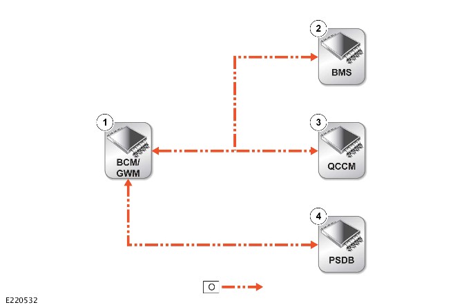
O = LOCAL INTERCONNECT NETWORK (LIN) BUS.
| ITEM | DESCRIPTION |
|---|---|
| 1 | Body Control Module/Gateway Module (BCM/GWM) |
| 2 | Battery Monitoring System (BMS) |
| 3 | Quiescent Current Control Module (QCCM) |
| 4 | Power Supply Distribution Box (PSDB) |
LOCAL INTERCONNECT NETWORK - GENERATOR
O = LOCAL INTERCONNECT NETWORK (LIN) BUS.
| ITEM | DESCRIPTION |
|---|---|
| 1 | Gateway Module (GWM) |
| 2 | Generator |
LOCAL INTERCONNECT NETWORK 2 - BODY CONTROL MODULE
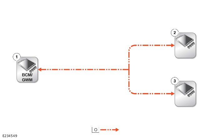
O = LOCAL INTERCONNECT NETWORK (LIN) BUS.
| ITEM | DESCRIPTION |
|---|---|
| Body Control MOdule/ Gateway MOdule (BCM/GWM) | |
| 2 | Front overhead console |
| 3 | Rain/light sensor |
LOCAL INTERCONNECT NETWORK 3 - BODY CONTROL MODULE
O = LOCAL INTERCONNECT NETWORK (LIN) BUS.
| ITEM | DESCRIPTION |
|---|---|
| Body Control Module/Gateway Module (BCM/GWM) | |
| 2 | Roof opening panel motor |
| 3 | Roof blind motor |
LOCAL INTERCONNECT NETWORK 4 - BODY CONTROL MODULE

O = LOCAL INTERCONNECT NETWORK (LIN) BUS.
| ITEM | DESCRIPTION |
|---|---|
| 1 | Body Control Module/ Gateway Module (BCM/GWM) |
| 2 | Immobilizer Antenna Unit (IAU) |
LOCAL INTERCONNECT NETWORK 4 - TAILGATE

O = LOCAL INTERCONNECT NETWORK (LIN) BUS.
| ITEM | DESCRIPTION |
|---|---|
| 1 | Remote Function Actuator (RFA) |
| 2 | Hands-free tailgate module - left |
| 3 | Hands-free tailgate module - right |
LOCAL INTERCONNECT NETWORK 5 - BODY CONTROL MODULE
O = LOCAL INTERCONNECT NETWORK (LIN) BUS.
| ITEM | DESCRIPTION |
|---|---|
| Body Control Module/ Gateway Module (BCM/GWM) | |
| 2 | Headlamp assembly right |
| 3 | Headlamp assembly left |
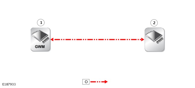
LOCAL INTERCONNECT NETWORK - DRIVER DOOR MODULE
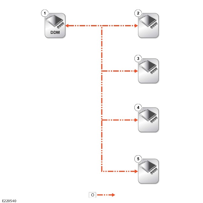
O = LOCAL INTERCONNECT NETWORK (LIN) BUS.
| ITEM | DESCRIPTION |
|---|---|
| 1 | Driver Door Module (DDM) |
| 2 | Driver door armrest illumination |
| 3 | Driver door illumination |
| 4 | Driver door illumination |
| 5 | Driver door switchpack |
LOCAL INTERCONNECT NETWORK - STEERING WHEEL
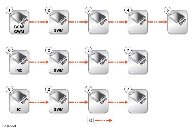
O = LOCAL INTERCONNECT NETWORK (LIN) BUS.
| ITEM | DESCRIPTION |
|---|---|
| 1 | Body Control Module/Gateway Module (BCM/GWM) |
| 2 | Steering Wheel Module (SWM) |
| 3 | Clockspring |
| 4 | Right steering wheel switchpack |
| 5 | Heated steering wheel control module |
| 6 | Infotainment Master Controller (IMC) |
| 7 | Left steering wheel switchpack |
| 8 | Instrument Cluster (IC) |
LOCAL INTERCONNECT NETWORK - POWERTRAIN CONTROL MODULE
O = LOCAL INTERCONNECT NETWORK (LIN) BUS.
| ITEM | DESCRIPTION |
|---|---|
| 1 | Powertrain Control MOdule (PCM) |
| 2 | Glow plug control module |
LOCAL INTERCONNECT NETWORK - FUEL FIRED BOOSTER HEATER
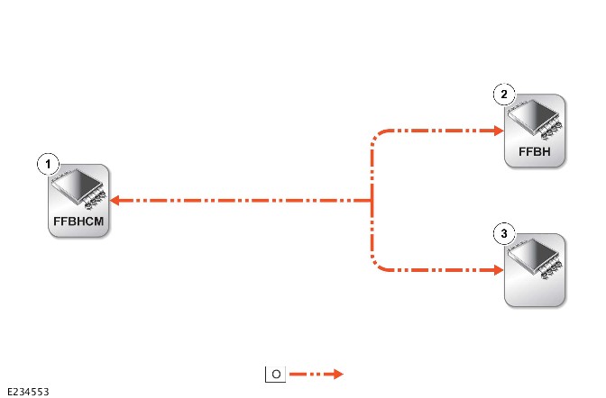
O = LOCAL INTERCONNECT NETWORK (LIN) BUS.
| ITEM | DESCRIPTION |
|---|---|
| 1 | Fuel Fired Booster Heater (FFBH) Control Module |
| 2 | FFBH blower |
| 3 | FFBH |
LOCAL INTERCONNECT NETWORK - DRIVER SEAT

| ITEM | DESCRIPTION |
|---|---|
| 1 | Driver seat switchpack |
| 2 | Driver Seat Module (DSM) |
LOCAL INTERCONNECT NETWORK - PASSENGER SEAT
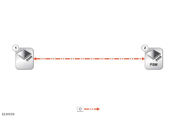
O = LOCAL INTERCONNECT NETWORK (LIN) BUS.
| ITEM | DESCRIPTION |
|---|---|
| 1 | Passenger seat switchpack |
| 2 | Passenger Seat Module (PSM) |
PRIVATE BUS - HEADLAMPS

U = PRIVATE BUS.
| ITEM | DESCRIPTION |
|---|---|
| 1 | Left headlamp |
| 2 | Right headlamp |
PRIVATE BUS - SIDE OBJECT DETECTION
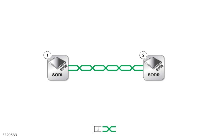
U = PRIVATE BUS.
| ITEM | DESCRIPTION |
|---|---|
| 1 | Side Object Detection Control Module - Left (SODL) |
| 2 | Side Object Detection Control Module - Right (SODR) |
MODULE COMMUNICATIONS NETWORK
COMMUNICATIONS NETWORK (G1818411)
DIAGNOSIS AND TESTING
PRINCIPLES OF OPERATION
For a detailed description of the Communications Network, refer to the relevant Description and Operation section in the workshop manual. REFER to: Communications Network (418-00 Module Communications Network, Description and Operation).
INSPECTION AND VERIFICATION
CAUTION:
Diagnosis by substitution from a donor vehicle is NOT acceptable. Substitution of control modules does not guarantee confirmation of a fault, and may also cause additional faults in the vehicle being tested and/or the donor vehicle.
NOTES:
- If a control module or a component is at fault or may be at fault and the vehicle remains under manufacturer warranty, refer to the Warranty Policy and Procedures manual, or determine if any prior approval program is in operation, prior to the installation of a new module/component.
- When performing voltage or resistance tests, always use a digital multimeter accurate to three decimal places, and with an up-to-date calibration certificate. When testing resistance always take the resistance of the digital multimeter leads into account.
- Inspect and rectify basic faults before beginning diagnostic routines involving pinpoint tests.
- Verify the customer concern
- Visually inspect for obvious signs of damage and system integrity
Visual Inspection
| ELECTRICAL |
|---|
|
- If an obvious cause for an observed or reported concern is found, correct the cause (if possible) before proceeding to the next step
- If the cause is not visually evident, verify the symptom and refer to the Symptom Chart, alternatively check for Diagnostic Trouble Codes (DTCs) and refer to the DTC Index
- Inspect the JLR claims submission system for open campaigns. Refer to the corresponding bulletins and SSMs which may be valid for the specific customer complaint and complete the recommendations as required.
COMMUNICATION NETWORK FAILURE PROCEDURE
The following instructions are for vehicles using the Pathfinder diagnostic tool.
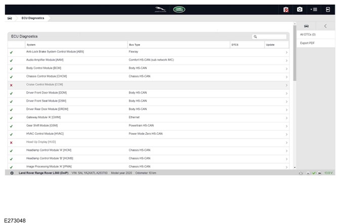
If a control module is suspected of non-communication, use the Pathfinder diagnostic tool and navigate to ‘ECU diagnostics’ (as seen in the image below).
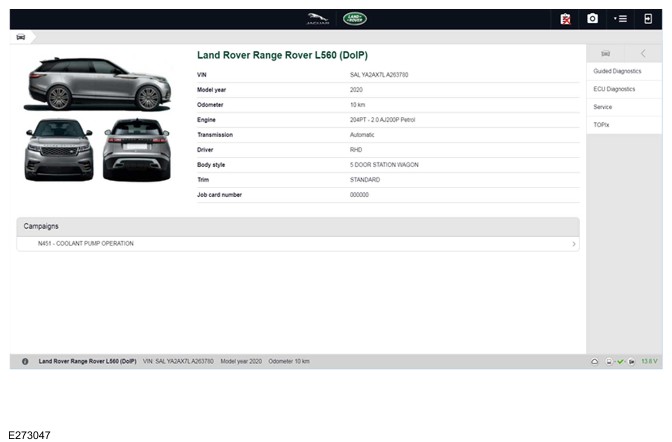
This will display a list of all control modules that are installed on the vehicle.
- Control modules that are communicating correctly will show a green tick at the left of the screen
- Control modules are not communicating will show a red cross at the left off the screen
This check can be used to determine if either a single module or multiple modules are failing to communicate (as seen in the image below).
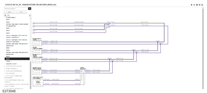
When all non-communicating module(s) have been identified, refer to the vehicle wiring diagrams (418-00 module communications), to identify the communication network at fault. If a single control module is failing to communicate inspect the module power supply circuit before continuing. When the communication network at fault has been identified and the non-communicating module(s) power supply has been confirmed, the approximate location of the network failure can be localized by identifying the final module on the network that can communicate via the network, then follow the network wiring downstream to the non-communicating module (example of communication network wiring diagram below). The network failure will be located between these modules, repair/replace the network wiring harness as necessary. For further diagnostics for the communication networks please refer to the Controller Area Network (CAN) and FlexRay sections below.
CONTROLLER AREA NETWORK (CAN)
Control Module Connections to the CAN Harness
Control modules are connected to the CAN harness either in a 'loop' or 'spur' configuration. In the 'loop' type configuration the CAN harness loops into the module (via two connector pins) and then loops out of the module (via another two connector pins). In the 'spur' type configuration, a harness spur is spliced into the main 'backbone' of the CAN harness and the module is connected to the harness spur via two connector pins.
CAN Harness Architecture
For a detailed description of the CAN Networks and architecture, refer to the relevant Description and Operation section in the Workshop Manual.
CAN Terminating Modules
If the communication Network failure procedure indicates that one or more module on one of the CAN networks (HS or MS) are failing to communicate, there are several checks that can be made. The first step is to identify if both of the CAN terminating modules on each individual CAN Bus are communicating. If both CAN terminating modules for each individual CAN Bus are communicating (identified via the Communication Network failure procedure), then it can be confirmed that the main 'backbone' of the CAN harness is complete. The main 'backbone' of the CAN harness consists of all the modules connected to the CAN harness via a 'loop' configuration and also includes the two terminating modules.
Communication with both CAN terminating modules via the Communication Network failure procedure test confirms the physical integrity of the main 'backbone' of the CAN harness (and the harness spur to the J1962 diagnostic connector). This means that there is no requirement to check the resistance of the CAN Network. This is because the standard check for 60 ohms across the CAN High and CAN Low lines will not provide any additional information regarding the physical condition of the CAN harness, beyond what has already been determined from the Communication Network failure procedure.
Non-Communication of a Terminating Module
If the Communication Network failure procedure reveals a terminating module is failing to communicate it can indicate a break in the main 'backbone' of the CAN harness. The first checks should always be to confirm the power and ground supplies to the non-communicating module are correct. Providing these are correct, the resistance between the CAN High and CAN Low lines at the J1962 connector can be checked to determine the integrity of the main 'backbone' of the CAN harness. After disconnecting the battery a reading of 120 ohms would indicate an open circuit in the main 'backbone' of the CAN harness. Alternatively, a reading of 60 ohms would indicate that there is no open circuit fault with the main 'backbone' of the CAN harness.
It is worth noting that even if one of the terminating modules is disconnected from the CAN harness, communications between the modules still connected may still be possible. Therefore communication between the manufacturer approved diagnostic system and the connected modules may also be possible.
Locating CAN Harness Open Circuits
In the case where multiple modules, including a terminating module, are failing to communicate, having first confirmed the power and ground supplies are correct, the approximate location of the open circuit can be identified from analysis of the Communication Network failure procedure results and reference to the relevant CAN network circuit diagrams. For example, if an open circuit existed in a certain position on the CAN harness, any module positioned on the Network between the J1962 connector and the open circuit should return a response during the Communication Network failure procedure. No responses would be returned from any modules past the open circuit fault in the Network.
CAN Harness 'Spur' Type Configuration Circuits
If, after the initial checks (Communication Network failure procedure using the manufacturer approved diagnostic system, and power and ground supplies to the module have been checked and confirmed as correct), a module that is connected to the CAN harness via a 'spur' type configuration is suspected of not communicating, then the physical integrity of the CAN harness 'spur' can be checked.
This is most easily undertaken by individually checking the continuity of the CAN High and CAN Low lines between the non-communicating module connector (with the module disconnected) and the J1962 diagnostic connector.
'Lost Communications' DTCs
As well as the methods described so far in this document, which can be used to determine the location of an open circuit in the CAN harness, 'Lost Communications' DTCs can also be used for this purpose. Lost communication DTCs mean that a module is not receiving CAN information from another module.
For example, if a global DTC read were to be carried out, only DTCs stored in the modules that the manufacturer approved diagnostic system could communicate with would be displayed. If there was an open circuit fault in a certain position on the CAN harness, the modules that could display DTCs would all be prior to the open circuit on the Network, and these modules should display 'Lost Communications' DTCs with all the modules located on the Network past the open circuit fault.
'Bus off' DTCs
The references to bus and its condition refer to the network concerned and the modules on that network.
If a module logs a 'Bus Off' DTC, it means that the module has detected CAN transmission errors and has disabled its own CAN transmissions and disconnected itself from the network in an attempt to allow the rest of the network to function. At this point the 'Bus Off' DTC is set. A common cause of 'Bus Off' DTCs can be a short circuit in the CAN network.
FLEXRAY
Control Module Connections to the FlexRay Harness
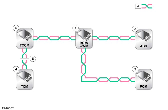
Control modules are connected to the FlexRay harness in a point to point and daisy chain type configuration. The Anti-lock Brake System Control Module (ABS) and Powertrain Control Module (PCM) are connected via a point to point connection. The Transmission Control Module (TCM) and Transfer Case Control Module (TCCM) (where fitted) are connected via the daisy chain connection (when a TCCM is fitted, if not the TCM would also be a point to point connection). In the daisy chain type configuration the FlexRay harness enters the module (via two connector pins) and then exits the module (via another two connector pins), as shown in the figure below.
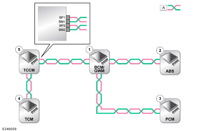
A=FLEXRAY NETWORK
| ITEM | DESCRIPTION |
|---|---|
| 1 | Body Control Module (BCM)/Gateway Module (GWM) |
| 2 | Anti-lock Brake System Control Module (ABS) |
| 3 | Powertrain Control Module (PCM) |
| 4 | Transmission Control Module (TCM) |
| 5 | Transfer Case Control Module (TCCM) where fitted |
FlexRay Harness Architecture
For a detailed description of the FlexRay harness architecture, refer to the relevant Description and Operation section in the workshop manual.
FlexRay Communication Check
If a control module is suspected of non-communication, a communication check available on the Jaguar Land Rover approved diagnostic equipment can be used to confirm if communication is possible between the control modules on the vehicle with the Jaguar Land Rover approved diagnostic equipment. The results from the test can be used to determine if either a single module or multiple modules are failing to communicate. Refer to the pinpoint test below for the steps to diagnose a FlexRay network fault.
FlexRay Network Integrity
If the communication check indicates that one or more modules on the FlexRay network are failing to communicate, there are several checks that can be made. The first step is to identify if the terminating modules on the FlexRay network are communicating, the terminating modules (which are required at both ends of each branch of the network) are located within the Gateway Module (GWM), the Anti-lock Braking System Control Module (ABS), the Powertrain Control Module (PCM), and the Transmission Control Module (TCM). If the terminating modules for the FlexRay network are communicating (identified via the communication check), then it can be confirmed that the FlexRay harness is complete.
Communication with the FlexRay terminating modules via the communication check confirms the physical integrity of the FlexRay harness. This means that there is no requirement to check the resistance of the FlexRay network. This is because the standard check for 90-100 ohms across the BP (Bus Plus) and BM (Bus Minus) will not provide any additional information regarding the physical condition of the FlexRay harness, beyond what has already been determined from the communication check. If however a communication check reveals a terminating module is failing to communicate it can indicate a break in the FlexRay harness. The first checks should always be to confirm the power and ground supplies to the non-communicating module are correct. Providing these are correct, details for how to check the integrity of a terminating module can be found below.
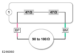
Checking Terminating Module Integrity
Firstly disconnect the module power supply, then measure the resistance between the module FlexRay Bus Plus (BP) and Bus Minus (BM) terminals. The expected resistance for a terminating module is between 90 and 100Ω any reading outside of this parameter may indicate module failure.
| ITEM | DESCRIPTION |
|---|---|
| 1 | Module |
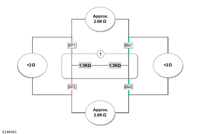
Checking Non-Terminating Module Integrity
Firstly disconnect the module power supply, then measure the resistance between the FlexRay terminals in the order listed below:
1. Bus Plus (BP) 1 and Bus Minus (BM) 1, the expected resistance for a non-terminating module is approximately 2.6kΩ
2. Bus Plus (BP) 2 and Bus Minus (BM) 2, the expected resistance for a non-terminating module is approximately 2.6kΩ
3. Bus Plus (BP) 1 and Bus Plus (BP) 2, the expected resistance for a non-terminating module is less than 2Ω
4. Bus Minus (BM) 1 and Bus Minus (BM) 2, the expected resistance for a non-terminating module is less than 2Ω
Any reading outside of these parameters may indicate a module failure.
| ITEM | DESCRIPTION |
|---|---|
| 1 | Module |
Locating FlexRay Harness Open Circuits
In the case where multiple modules, including the terminating modules, are failing to communicate, having first confirmed the power and ground supplies are correct, the approximate location of the open circuit can be identified from analysis of the communication check results. No responses would be returned from any modules past the open circuit fault in the network (please refer to the diagram below). Any short circuit, open circuit, or high resistance faults detected on the FlexRay harness should be repaired in accordance with the Jaguar Land Rover approved wiring harness repair procedure maintaining 90 to 100 ohms across the FlexRay network, maintaining the wire twist rate (20mm+/-2mm for one full 360° twist), using no more than of five in-line connectors on each branch of the FlexRay network. For further information refer to section 418-02 Wiring Harness, Description and operation, in the workshop manual.
A=FLEXRAY NETWORK
| ITEM | DESCRIPTION |
|---|---|
| 1 | Body Control Module (BCM)/Gateway Module (GWM) |
| 2 | Anti-lock Brake System Control Module (ABS) |
| 3 | Powertrain Control Module (PCM) |
| 4 | Transmission Control Module (TCM) located after the open circuit in the FlexRay network causing "Lost Communication" DTCs with other modules on the FlexRay network |
| 5 | Transfer Case Control Module (TCCM) (where fitted) prior to the FlexRay network open circuit showing "Lost Communication" DTCs |
| 6 | FlexRay network open circuit |
FlexRay 'Bus off' DTCs
The references to bus and its condition refer to the network concerned and the modules on that network.
If a module logs a 'Bus off' DTC, it means that the network has detected FlexRay transmission errors and has disabled its own FlexRay transmissions and disconnected itself from the network in an attempt to allow the rest of the network to function. At this point the 'Bus off' DTC is set. A common cause of 'Bus off' DTCs can be a short circuit in the FlexRay network. Any short circuit, open circuit, or high resistance faults detected in the FlexRay harness should be repaired in accordance with the Jaguar Land Rover approved wiring harness repair procedure maintaining 100 ohms across the FlexRay network and also maintaining the wire twist rate.
FLEXRAY PINPOINT TESTS
| PINPOINT TEST A : CHECKING FLEXRAY INTEGRITY | |
|---|---|
| A1: FLEXRAY NETWORK INTEGRITY | |
| TEST CONDITIONS | DETAILS/RESULTS/ACTIONS |
| 1 Firstly check the FlexRay network integrity. | |
| Connect the Jaguar Land Rover approved diagnostic equipment to the vehicle and perform the Communication Network failure procedure. Has a fault been identified on the FlexRay network? Yes No fault has been detected within the FlexRay network. No GO to A2. |
| A2: TERMINATING MODULE CONNECTION | |
|---|---|
| TEST CONDITIONS | DETAILS/RESULTS/ACTIONS |
| 1 Termination module integrity check. | |
| Refer to the FlexRay communication check and confirm whether the termination modules are communicating. Yes The termination modules are communicatingGO to A3. No The termination modules are not communicatingGO to A4. |
| A3: NON-TERMINATING MODULE CONNECTION | |
|---|---|
| TEST CONDITIONS | DETAILS/RESULTS/ACTIONS |
| 1 Non-terminating module integrity check. | |
| Using the Jaguar Land Rover approved diagnostic equipment and the circuit diagrams, check the non-communicating module power and ground supplies, are these correct? Yes Using the Jaguar Land Rover approved diagnostic device, check the DTCs and refer to the relevant DTC index and perform the suggested corrective actions, module replacement may be advised. No Refer to the circuit diagrams and check the module power and ground supply circuits for short circuit to power, short circuit to ground, open circuit, or high resistance. Repair the circuit as required and retest. |
| A4: TERMINATING MODULE POWER SUPPLY CHECK | |
|---|---|
| TEST CONDITIONS | DETAILS/RESULTS/ACTIONS |
| 1 Module power supply and ground check. | |
| Using the Jaguar Land Rover approved diagnostic equipment and circuit diagrams, check the communicating termination module power and ground supplies, are these correct? Yes GO to A5. No Refer to the circuit diagrams and check the termination module power and ground supply circuits for short circuit to power, short circuit to ground, open circuit, or high resistance. Repair the circuit as required and retest. |
| A5: FLEXRAY NETWORK RESISTANCE CHECK | |
|---|---|
| TEST CONDITIONS | DETAILS/RESULTS/ACTIONS |
| 1 Check the resistance of the FlexRay network. | |
| Are the results between 90-100 ohms? Yes Using the Jaguar Land Rover approved diagnostic equipment, check the DTCs and refer to the relevant DTC index and perform the suggested corrective actions, module replacement may be advised. No Refer to the electrical circuit diagrams and check the FlexRay harness for open circuit or high resistance. Repair the circuit as required and retest. |
BROADR-REACH® ETHERNET
The infotainment control modules use the BroadR-Reach® Ethernet network connection to communicate, for a detailed description of the BroadR-Reach® Ethernet network please refer to the relevant Description and Operation section of the workshop manual. The BroadR-Reach® Ethernet network is constantly monitored by the modules connected, any fault within the BroadR-Reach® Ethernet network raises a DTC in the associated module. For any related diagnostics to the BroadR-Reach® Ethernet network, please check for DTCs and refer to the relevant DTC index.
DTC INDEX
For a list of Diagnostic Trouble Codes (DTCs) that could be logged on this vehicle, please refer to Section 100-00. REFER to: Diagnostic Trouble Code Index - DTC: Body Control Module (BCM) (100-00 General Information, Description and Operation).
MODULE COMMUNICATIONS NETWORK
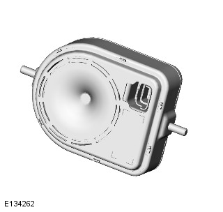
QUIESCENT CURRENT CONTROL MODULE (G1913538)
REMOVAL AND INSTALLATION
- 86.80.48
- QUIESCENT CURRENT CONTROL MODULE - RENEW
- ALL DERIVATIVES
- 1.00
- USED WITHINS
REMOVAL
NOTE:
Removal steps in this procedure may contain installation details.
- Refer to: Startup Battery Disconnect and Connect (414-01 Battery, Mounting and Cables, General Procedures).
- Refer to: Loadspace Side Trim Panel (501-05 Interior Trim and Ornamentation, Removal and Installation).
Torque: 9Nm
INSTALLATION
- To install reverse the removal procedure.
- NOTE:
This step is only necessary when installing a new component.
Using Jaguar approved diagnostic equipment, reset the battery monitoring system.
MODULE COMMUNICATIONS NETWORK
BODY CONTROL MODULE/GATEWAY MODULE ASSEMBLY (G1862784)
REMOVAL AND INSTALLATION
GENERAL EQUIPMENT
| EQUIPMENT NAME |
|---|
| Jaguar Land Rover approved diagnostic equipment |
REMOVAL
NOTES:
- If a new Body Control Module/Gateway Module (BCM/GWM) is installed, a new Remote Function Actuator (RFA) must also be installed. This step is only required for vehicles that are 15MY or later. This step is not required for North American Specification (NAS) vehicles. Use the approved Jaguar Land Rover (JLR) diagnostic equipment to configure the new RFA.
- Make sure all of the keys are present before this procedure is carried out.
- A maximum of 8 remote transmitters can be programmed to the BCM/GWM. Programming for all remote transmitters must be carried out at the same time.
- This procedure contains some variation in the illustrations depending on the vehicle specification, but the essential information is always correct.
- This procedure contains illustrations showing certain components removed to provide extra clarity.
- If a new BCM/GWM is installed, use the approved Jaguar Land Rover diagnostic equipment to download the stored data.General Equipment: Jaguar Land Rover approved diagnostic equipment
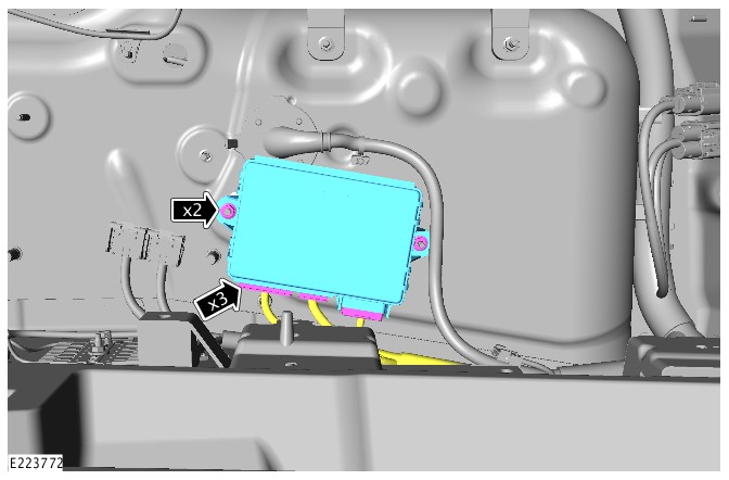
- Disconnect the startup battery ground cable.Refer to: Startup Battery Disconnect and Connect (414-01 Battery, Mounting and Cables, General Procedures).
- Remove the cowl side trim panel.Refer to: Cowl Side Trim Panel (501-05 Interior Trim and Ornamentation, Removal and Installation).
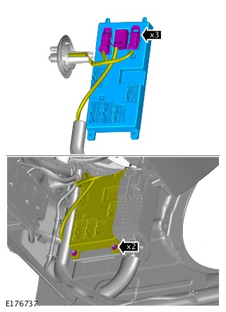
Disconnect the 5 electrical connectors.
- Remove the 2 nuts.
- Reposition the Body Control Module/Gateway Module (BCM/GWM) assembly.
- Disconnect the 3 electrical connectors.
- Remove the BCM/GWM assembly.
INSTALLATION
- Connect the 3 electrical connectors to the Body Control Module/Gateway Module (BCM/GWM) assembly.
- Install the BCM/GWM assembly.
- Install and tighten the 2 nuts.Torque: 10Nm
- Connect the 5 electrical connectors to the BCM/GWM assembly.
ANTI-THEFT - ACTIVE (G1917575)
DESCRIPTION AND OPERATION
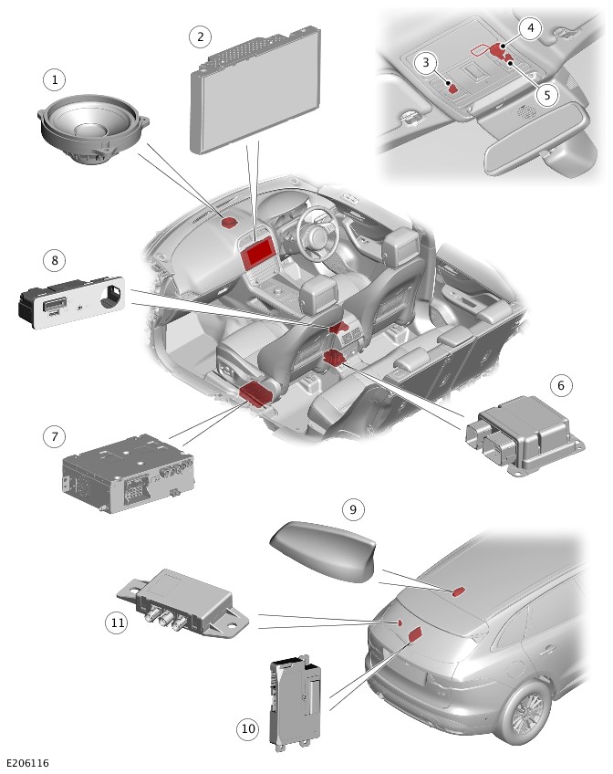
COMPONENT LOCATION - 1 OF 2
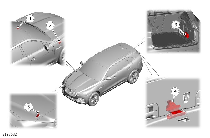
| ITEM | DESCRIPTION |
|---|---|
| 1 | Volumetric sensor |
| 2 | Passive sounder - if equipped |
| 3 | Remote Function Actuator (RFA) |
| 4 | Hood switch |
| 5 | Tailgate latch |
COMPONENT LOCATION - 2 OF 2
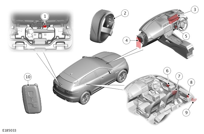
| ITEM | DESCRIPTION |
|---|---|
| 1 | Activity Key Transceiver Module - if equipped |
| 2 | Activity Key - (if equipped) |
| 3 | Instrument Cluster (IC) |
| 4 | Body Control Module/Gateway Module (BCM/GWM) assembly |
| 5 | Immobilizer Antenna Unit (IAU) |
| 6 | Driver Door Module (DDM) (passenger side fitted with a Passenger Door Module (PDM)) |
| 7 | Driver door latch (passenger door latch is the same) |
| 8 | Rear Door Module (RDM) (2 of) |
| 9 | Rear door latch (2 of) |
| 10 | Smart key |
OVERVIEW
The active anti-theft system monitors the hinged panels for unauthorized opening. In some markets the anti-theft system also incorporates monitoring of the vehicle interior and vehicle tilt sensing.
The active anti-theft alarm system comprises the following modules:
- Body Control Module/Gateway Module (BCM/GWM) assembly
- Driver Door Module (DDM)
- Passenger Door Module (PDM)
- Rear Door Module (RDM) left/right
- Instrument Cluster (IC).
The BCM/GWM assembly is the main controller in the system. The BCM/GWM assembly controls the following security functions, in addition to other vehicle functions:
- Locking, double locking and unlocking.
- Monitoring of hood switch and ajar switches in the door latches and the tailgate latch of the Central Door Locking (CDL) system.
- Passive arming and disarming.
- Panic alarm function.
- Security Sounder - Battery Back Up Sounder (BBUS), or Passive Sounder, and vehicle horns (market dependent).
- Volumetric sensor.
- Smart key transponder reading.
- Interior lighting.
Two levels of vehicle anti-theft alarm are available:
- Perimeter mode - Monitors all opening panels.
- Volumetric mode monitors the vehicle interior for intrusion and it also incorporates a tilt sensor to monitor if the vehicle is being moved.
Perimeter Sensing - all apertures (doors, tailgate , hood) are monitored for ajar status (doors ajar and latch status change) and a visual (via directional indicators) and audible alarm is emitted via security sounder and vehicle horns (market dependent) in the event of unauthorized access. The alarm is also triggered in the event of an unauthorized ignition request.
NOTE:
Volumetric mode and tilt sensing are not available in certain markets.
The smart key provides the following functionality:
- Unlock (central unlock or single point entry).
- Lock and double lock.
- Tailgate release.
- Approach lighting.
- Panic alarm.
The lock and unlock switches also control a 'lazy' lock and unlock feature which will automatically close or open the windows with an extended press of the applicable switch. This feature is only available in certain markets and is controlled in conjunction with the door modules.
WARNING:
Never double lock the vehicle with any person or animal inside.
NOTE:
Double locking is only available in certain markets.
The smart key contains an emergency key. This can be used in the event of failure of the smart key or the vehicle battery to unlock the vehicle. The driver door handle contains a concealed mechanical key barrel which can be used with the emergency key to access the vehicle. This will not disable the perimeter or interior alarm systems which will be activated when the door is opened. To cancel the alarm, the smart key must be held next to the Immobilizer Antenna Unit (IAU) and the Stop/start switch must be operate.For additional information, refer to: Handles, Locks, Latches and Entry Systems (501-14 Handles, Locks, Latches and Entry Systems, Description and Operation).
Emergency Locking - On each shut face of each door there is an emergency locking aperture. This is for use with the emergency access key in the event of a failure of the vehicle battery, to lock the vehicle. Remove the cover and insert the key into the aperture to mechanically lock each door in turn, the driver door being the last door to be locked. Please ensure that the key is removed from the emergency locking aperture before each door is closed.
DESCRIPTION
DOOR MODULES
The door modules provide the interface between the door latch motors, the door and latch switches and the BCM/GWM assembly. The door modules provide door micro switch status information and enable the door motors on request from the BCM/GWM assembly.
The Rear Door Modules (RDM) are also controlled by the BCM/GWM assembly. Additionally, the front door modules also control the exterior mirror functions.
BODY CONTROL MODULE/GATEWAY MODULE (BCM/GWM) ASSEMBLY
The BCM/GWM assembly controls the following functions:
- The horns.
- The tailgate latch motor and micro switches (including the tailgate external release switch).
- The tailgate ajar switch.
- The turn signal indicators.
- The fuel flap operation.
The BCM/GWM assembly also has a connection to the Restraints Control Module (RCM) for automatic operation of the interior lights and the turn signal indicators in the event of an accident.
NOTE:
If the BCM/GWM assembly is replaced, the new module will require configuring to the master car configuration using a Jaguar approved diagnostic system.
The BCM/GWM assembly automatically arms and disarms the active anti-theft system when the vehicle is locked and unlocked after successful confirmation that a valid smart key has been used.
INSTRUMENT CLUSTER (IC)
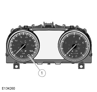
| ITEM | DESCRIPTION |
|---|---|
| 1 | Alarm Indicator |
The Instrument Cluster (IC) controls the alarm indicator which is incorporated in the main display in the IC.
The IC also controls, in conjunction with the Body Control Module/Gateway Module (BCM/GWM) assembly the Powertrain Control Module (PCM) and the Anti-lock Brake System (ABS) control module, the engine immobilization. The PCM controls the engine crank and fuel functions and the ABS control module controls the tilt function. The PCM and ABS control module communicate to each other after the BCM/GWM assembly processes the valid smart key information.
Alarm Warning Indicator
The alarm warning indicator is a red Light Emitting Diode (LED) located in the IC. When the ignition is switched off, the indicator gives a visual indication of the active anti-theft system to show if the alarm system is set or unset. When the ignition is switched on, the indicator provides a visual indication of the status of the passive anti-theft (engine immobilization) system. If the immobilization system is operating correctly, the LED will be illuminated for 3 seconds at ignition on and then extinguish.
If a fault exists in the immobilization system, the LED will be either permanently illuminated or flashing for 60 seconds. This indicates that a fault exists and a Diagnostic Trouble Code (DTC) has been recorded. After the 60 second period, the LED will flash at different frequencies which indicate the nature of the fault.
Operation of the alarm indicator is controlled by the IC which varies the flash rate of the LED to indicate the system status of the alarm and the immobilization systems.
| ALARM/IMMOBILIZATION STATUS | ALARM INDICATOR STATUS | ALARM INDICATOR FUNCTION |
|---|---|---|
| UNSET | No flash | LED will flash twice quickly with a long interval between and is repeated 10 times. Slow 'active' flash then follows. |
| SET - with perimeter alarm | Flashing | LED will flash twice quickly with a long interval between and is repeated 10 times. Slow 'active' flash then follows. |
| SET - with volumetric alarm | Flashing | LED will flash three times quickly with a long interval in between and is repeated 10 times. Slow 'active' flash then follows. |
| ACTIVE | Flashing | Slow flash once alarm is activated at a frequency of 100ms on and 200 ms off. |
| UNSET - alarm activated during previous SET cycle | Flashing rapidly | LED will flash rapidly until the BCM/GWM assembly receives an accessory power mode 4 signal. |
PASSIVE SOUNDER
The passive sounder is located in the engine compartment behind the secondary bulkhead panel on the driver side. The passive sounder is connected directly to the BCM/GWM assembly which activates the passive sounder as a secondary security sounder when the alarm is triggered.
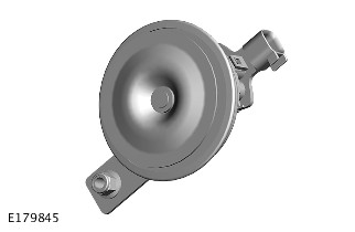
VEHICLE HORNS
NOTE:
Some variation in the illustrations may occur, but the essential information is always correct

The vehicle horns are located above the front bumper armature. The horns have a switched power supply via the horn relay located in the Engine Junction Box - 1 (EJB 1). The horns are switched via the steering wheel, connected through the Clockspring (CLKSPG) to the BCM/GWM assembly which activates the horns as a secondary security sounder when the alarm is triggered.
BATTERY BACK UP SOUNDER (BBUS)
The Battery Back-Up Sounder (BBUS) is located in the engine compartment behind the secondary bulkhead panel on the driver side. The sounder is only fitted in certain markets and is mandatory fit in UK vehicles.
The BBUS incorporates an integrated tilt sensor which monitors the vehicle attitude. The tilt sensor can detect if the vehicle is being moved, towed or raised and will communicate to the BCM/GWM assembly in order to indicate a trigger to activate the alarm.
Operation (SET/UNSET) of the BBUS and tilt sensor is controlled by the BCM/GWM assembly on the Local Interconnect Network (LIN) bus. An integral, rechargeable battery powers the BBUS if the vehicle battery supply from the BCM/GWM assembly is interrupted.
VOLUMETRIC SENSOR
The module is located in a central position in the front overhead console.
Double Locking Vehicles - The volumetric sensors are activated when the vehicle is double locked. The vehicle can be locked and alarmed with the volumetric sensors deactivated if a pet is to be left in the vehicle for example, by single locking the anti-theft active system.
When volumetric sensors are active and the vehicle battery voltage falls below 9 Volts, the BCM/GWM assembly ignore any inputs from the sensors to prevent false alarm activation.
The BCM/GWM assembly ignores the signals from the volumetric sensor for the first 30 seconds to allow time for the vehicle interior to settle and prevent false alarm activation.
If the tailgate is opened via the smart key, the volumetric sensor and the tilt sensor are inhibited until the tailgate is closed.
HOOD SWITCH
The hood switch is attached to the underside of the right hood latch and operated by movement of the latch mechanism. When the latch opens, the switch closes and connects a ground to the BCM/GWM assembly.
OPERATION
The Body Control Module/Gateway Module (BCM/GWM) Assembly automatically arms and disarms the active anti-theft system when it operates the Central Door Locking (CDL) system. The BCM/GWM assembly also locks and unlocks the Electric Steering Column Lock (ESCL) (if equipped) when it operates the CDL system
On vehicles without a volumetric sensor, only the perimeter mode is available to monitor the hinged panels and the validity of the smart key.
When perimeter sensing is active, the BCM/GWM assembly monitors aperture ajar switches located in the latch mechanisms of the front and rear doors, the tailgate and hood ajar micro switch, located in hood latch mechanism in the engine compartment.
When volumetric sensors are active, the BCM/GWM assembly monitors the interior of the vehicle for movement using a volumetric sensor located the front overhead console.
Arming
Perimeter mode
On vehicles without a volumetric sensor, the anti-theft active system is armed in the perimeter mode when the vehicle is either locked or double locked using the lock switch on the smart key or, on vehicles with the passive entry system, the lock/unlock switch on one of the exterior door handles. Smart key switch selection and the lock/unlock switch selection on the exterior door handles are relayed to the BCM/GWM assembly by the Remote function Actuator (RFA) on the Medium Speed (MS) Controller Area Network (CAN) body systems bus.
Perimeter sensing only monitors the hinged panels and validity of the smart key in the (RFA).
Volumetric mode
Volumetric sensing monitors the vehicle interior for intrusion. If the vehicle is fitted with a BBUS, which incorporates a tilt sensor, the vehicle altitude is also monitored when volumetric mode is active. Volumetric mode is activated by a second press of the lock switch on the smart key or, on vehicles with the passive entry system, the lock switch on one of the exterior door handles. The second press of the switch must occur within 3 seconds of the first press. The second press of the lock switch also activates the perimeter sensing double locking feature.
On single locking, vehicles where volumetric sensors are fitted, volumetric sensing is activated by a single press of the lock switch on the smart key/keyless vehicle exterior lock switch.
The BCM/GWM assembly arms the active anti-theft system when it single locks or double locks the vehicle, providing all the following conditions are met:
- All doors, tailgate and hood are closed.
- The BCM/GWM assembly is not in transit mode.
- The smart key is not sensed inside the vehicle.
When the vehicle has successfully completed its locking routine, confirmation will be given by a single short flash of the turn signal indicators to indicate a single locked condition. If double locking is activated, then the confirmation will be given by a double flash of the turn signal indicators, one short flash for locked and one long flash on completion of double locked.
Mislock
If any doors, tailgate or hood is open/ajar, or if the ignition is switched on, when a lock or double lock request is received, the anti-theft alarm system remains disarmed and the BCM/GWM assembly generates a short mislock sound from the security sounder (BBUS or passive sounder) and the turn signal indicators will not flash. Each attempt to lock will be confirmed by an audible chime being emitted.
If the tailgate is opened via the smart key, the volumetric sensor and the tilt sensor in the BBUS are inhibited until the tailgate compartment lid is closed.
Disarming
The BCM/GWM assembly will disarm the active anti-theft system to prevent false alarm activation under certain conditions as follows:
- When the active anti-theft system is armed in volumetric mode and if the vehicle battery voltage decreases to less than 9 volts, the BCM/GWM assembly will disable the volumetric mode and remain in perimeter mode only. This prevents false alarm activation because the volumetric sensor cannot operate correctly below 9 volts.
- On vehicles fitted with a BBUS, and the vehicle battery voltage decreases from 9.5 to 9 Volts in more than a 30 minute period, the BCM/GWM assembly de-activates the BBUS and, if required, will use the vehicle horns to sound an audible alarm trigger warning. This prevents false alarm activation. At voltages below 9 Volts, the BCM/GWM assembly will not generate the 'heartbeat' signal to the BBUS. The BBUS interprets this as the BCM/GWM assembly has been tampered with and activates its sounder. If the battery voltage subsequently rises to more than 9.5 Volts, the BCM/GWM assembly will re-arm the BBUS.
- If the vehicle is unlocked using the unlock switch on the smart key and, within 40 seconds a hinged panel is not opened, automatically re-locks the vehicle and re-arms the active anti-theft system. This prevents leaving the vehicle unlocked and disarmed by accidental operation of the smart key unlock switch.
Alarm
When the alarm is triggered, the BCM/GWM assembly activates audible and visual warnings. The audible warnings are produced by the security sounders - Passive sounder or the BBUS and vehicle horns (market dependent). Visible indications are produced using the turn signal indicators.
The BCM/GWM assembly activates the security sounders - Passive sounder or the BBUS and vehicle horns (market dependent) and the visual indications for 30/60 seconds, depending on the market. The activation is stopped for 10 seconds and, if the alarm trigger is still present, the BCM/GWM assembly will cycle again for 30/60 seconds. This will be repeated for up to a maximum of 10 cycles per trigger source (3 cycles in certain markets) of 30/60 seconds for any one arming period. The BCM/GWM assembly will ignore the trigger cause if the 10 cycles (3 cycles in certain markets) have been completed and the alarm trigger is still present or until it receives a disarm signal.
NOTE:
If the Battery Back Up Sounder (BBUS) is triggered due to tamper detection, the visual indication using the turn signal indicators is not activated.
The alarm can be triggered by any of the hinged panels being opened or doors unlocked, the volumetric sensor detects a movement inside the vehicle, the tilt sensor detects vehicle movement or an ignition tamper is detected (invalid smart key).
Battery Back Up Sounder (BBUS)
NOTE:
If a BBUS is fitted, it is also armed with the perimeter mode lock request. However, the tilt functionality is not enabled in perimeter mode.
On receipt of the arming signals, the Battery Back Up Sounder (BBUS) and the tilt sensor respond with a status message. If the BCM/GWM assembly does not receive the status signals within a period of time, the BCM/GWM assembly assumes there is a fault and responds with a disarm signal to either the sounder and/or the tilt sensor and stores a related Diagnostic Trouble Code (DTC). If the sounder is disarmed when the active anti-theft system is armed and the system is subsequently triggered, the BCM/GWM assembly still energizes the horn relay and uses the vehicle horns to sound the audible warning in place of the BBUS.
When the BBUS is armed, the BCM/GWM assembly sends a periodic (heartbeat) signal to the sounder which prompts the sounder to monitor the vehicle battery supply and the Local Interconnect Network (LIN) bus link with the BCM/GWM assembly. The sounder will operate if:
- It receives an alarm signal from the BCM/GWM assembly or the tilt sensor.
- The power supply or the LIN bus link to the BCM/GWM assembly is disrupted.
The tilt sensor measures the longitudinal and lateral angle of the vehicle over a range of ±16 degrees from the horizontal. When the active anti-theft system is armed in volumetric mode, the tilt sensor stores the current vehicle angles in its memory and monitors the tilt sensor readings. If the vehicle angle changes in either direction by more than the alarm limit threshold, the tilt sensor communicates to the BCM/GWM assembly in order to activate the alarm sounder.
If the alarm system is active and the battery or the BBUS is disconnected, the BBUS will continue to sound without the visual indication of the turn signal indicators flashing.
PANIC ALARM
A panic alarm feature allows the vehicle alarm system to be activated using the smart key. The panic alarm switch, identified by a triangle symbol, can be operate and held for more than 3 seconds to activate the vehicle alarm.
To cancel the panic alarm feature, operate the panic alarm switch three times, press and hold the panic switch for 3 seconds or press the stop/start switch. To prevent accidental cancellation, the panic alarm cannot be cancelled within 5 seconds of being activated.
SMART KEY ADDITIONAL FEATURES
In addition to the lock and unlock switches, the smart key has convenience switches.
Headlamp Convenience
A headlamp convenience switch can be pressed to operate the headlamps to assist departure or approach to the vehicle. A single press of the switch will operate the headlamps for approximately 25 seconds, after which time they will automatically turn off. A second press of the switch will turn off the headlamps if the 25 second period has not been reached. Pressing the stop/start switch within the 25 second period will also turn off the headlamp convenience feature.
Convenience mode
When the vehicle is unlocked using the unlock switch on the smart key, the vehicle's electrical system initiates convenience mode.
The following systems become active in convenience mode:
- Memory - seat adjustment and mirror position
- Interior and exterior lighting
- Audio system
- IC message center
- Horn
- Cigar lighter/12V accessory socket.
Single Point Entry
The single point entry feature only unlocks the driver door, all other doors remain locked. A single press of the unlock switch on the smart key will unlock only the driver door, a second press is required to unlock the remaining doors and the luggage compartment lid.
If the vehicle is double locked, the first press of the unlock switch on the smart key unlocks the driver door. The remaining doors revert to the single locked state and can therefore be unlocked using the interior door handles, the smart key unlock switch or the unlock switch on the tailgate latch.
Changing from central locking to single point entry can be carried out by pressing the lock and unlock switches on the smart key simultaneously. The turn signal indicators will flash to confirm that the function change has been performed.
Global Open/Close
A global open and close feature can be operated from the smart key. This feature allows the vehicle windows to be opened/closed by a single press of the lock or unlock switch. The switch must be pressed and held for more than 2 seconds to activate the global open/close feature. The global open/close feature is not available in all markets. The windows must be initialized for the global functionality to work.
CONTROL DIAGRAM

A = HARDWIRED; O = LOCAL INTERCONNECT NETWORK (LIN) BUS; AN = HIGH SPEED (HS) CONTROLLER AREA NETWORK (CAN) POWERTRAIN SYSTEMS BUS; AO = MEDIUM SPEED (MS) CAN BODY SYSTEMS BUS.
| ITEM | DESCRIPTION |
|---|---|
| 1 | Body Control Module/Gateway Module (BCM/GWM) assembly |
| 2 | Instrument Cluster (IC) |
| 3 | Driver Door Module (DDM) |
| 4 | Passenger Door Module (PDM) |
| 5 | Driver side rear door module (RDM R) |
| 6 | Passenger side rear door module (RDM L) |
| 7 | Remote Function Actuator (RFA) |
| 8 | Instrument Cluster (IC) |
| 9 | Passive sounder |
| 10 | Tailgate latch |
| 11 | Battery Back-Up Sounder (BBUS) - if equipped |
| 12 | Overhead console |
| 13 | Volumetric sensor |
| 14 | Ground |
| 15 | Power supply |
| 16 | Front right door ajar switch |
| 17 | Front left door ajar switch |
| 18 | Rear right door ajar switch |
| 19 | Rear left door ajar switch |
| 20 | Hood switch |
PRINCIPLES OF OPERATION
For a detailed description of the anti-theft - active system, refer to the relevant description and operation sections in the workshop manual. REFER to: Anti-Theft - Active (419-01A Anti-Theft - Active, Description and Operation).
INSPECTION AND VERIFICATION
CAUTION:
Diagnosis by substitution from a donor vehicle is NOT acceptable. Substitution of control modules does not guarantee confirmation of a fault, and may also cause additional faults in the vehicle being tested and/or the donor vehicle.
- Verify the customer concern
- Visually inspect for obvious signs of damage and system integrity
Visual Inspection
| MECHANICAL | ELECTRICAL |
|---|---|
|
|
- If an obvious cause for an observed or reported concern is found, correct the cause (if possible) before proceeding to the next step
- If the cause is not visually evident, check for Diagnostic Trouble Code(s) and refer to the relevant Diagnostic Trouble Code(s) (DTC) Index
NOTE:
For remote keyless entry system failures:
REFER to: Diagnostic Trouble Code Index - DTC: Gateway Module (GWM) (100-00 General Information, Description and Operation).
SYMPTOM CHART

CORRECT INSTALLATION OF THE VOLUMETRIC SENSOR
The volumetric sensor is located in a central position in the overhead console. The volumetric sensor allows the interior of the vehicle to be monitored when the vehicle is double locked. In cases where customers have reported "false-alarm" triggers of the vehicle anti-theft alarm and where the volumetric sensor has been identified as the last known alarm trigger (see diagnostic instructions below), this may indicate an issue with the installation of the volumetric sensor rather than an internal failure of the sensor itself.
In light of this, when first faced with this issue, the existing volumetric sensor should be carefully removed and refitted. Care should be taken to make sure that the sensor and associated connectors are installed correctly and securely. See illustration and video for correct installation, when installed conduct 'push-pull-push' on connections to make sure of correct engagement. Make sure the sensors are pushed fully home and abut against the console, there should be equal placement all around the sensor and it should not be angled when compared to the surface of the console, no large visible gap should be seen and any small gap should be equal all around the sensor when viewed from the front and the rear of the console, use a flashlight to aid with gap visibility, REFER to: Overhead Console (501-12 Instrument Panel and Console, Removal and Installation).
If the issue reoccurs after refitting of the volumetric sensor, then the sensor should be replaced.
READING ALARM TRIGGER HISTORY THROUGH PATHFINDER DIAGNOSTICS
NOTE:
Make sure to take a recording of the alarm trigger history and add this to the warranty claim
To determine the details of recent anti-theft alarm triggers on Pathfinder vehicles, the following steps should be followed:
- Using the Jaguar Land Rover approved diagnostic equipment, connect to the vehicle through the Vehicle Communication Interface (VCI) unit
- Load in the Vehicle Identification Number (VIN)
- SELECT 'ECU Diagnostics'
- SELECT 'Body Control Module (BCM)'
- SELECT 'ECU Functions From List'
- SELECT 'Alarm Trigger History' and follow on-screen instructions to view recent alarm trigger history
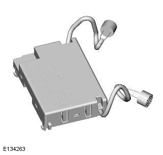
REMOTE FUNCTION ACTUATOR (G2254723)
REMOVAL AND INSTALLATION
- 86.80.08
- REMOTE FUNCTION ACTUATOR (RFA) - RENEW
- ALL DERIVATIVES
- 1.00
- USED WITHINS
GENERAL EQUIPMENT
| EQUIPMENT NAME |
|---|
| Jaguar Land Rover approved diagnostic equipment |
REMOVAL
NOTES:
- This procedure contains some variation in the illustrations depending on the vehicle specification, but the essential information is always correct.
- This procedure contains illustrations showing certain components removed to provide extra clarity.
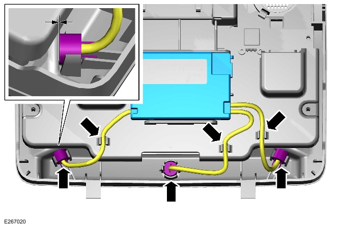
- Remove the right side loadspace trim panel.Refer to: Loadspace Side Trim Panel (501-05 Interior Trim and Ornamentation, Removal and Installation).
- Disconnect the startup battery ground cable.Refer to: Specifications (414-01 Battery, Mounting and Cables, Specifications).
Release the retaining clip.
- Disconnect the 3 electrical connectors.
- Remove the 2 retaining bolts.
- Remove the remote function actuator.
INSTALLATION
- Install the remote function actuator.
- Connect the 3 electrical connectors.
- Install the retaining bolts.Torque: 9Nm
TELEMATICS (G2127852)
DESCRIPTION AND OPERATION
COMPONENT LOCATION
COMPONENT LOCATION - VEHICLES WITH INCONTROL TOUCH AUDIO SYSTEMS
| ITEM | DESCRIPTION |
|---|---|
| 1 | Telematics speaker |
| 2 | Touchscreen (TS) |
| 3 | Breakdown call (bCall) switch |
| 4 | Microphone |
| 5 | Emergency call (eCall) switch |
| 6 | Restraints Control Module (RCM) |
| 7 | Audio Head Unit (AHU) |
| 8 | Portable audio interface panel |
| 9 | Roof pod |
| 10 | Telematics Control Module (TCU) |
| 11 | Global Positioning System (GPS) signal splitter |
COMPONENT LOCATION - VEHICLES WITH INCONTROL TOUCH PRO AUDIO SYSTEMS
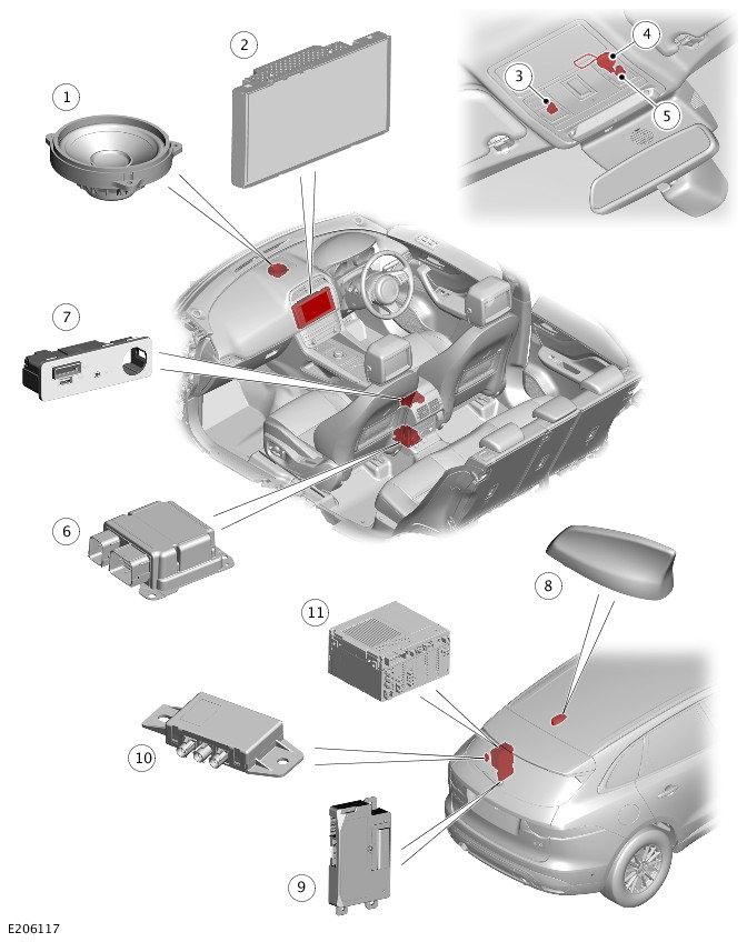
| ITEM | DESCRIPTION |
|---|---|
| 1 | Co-axial speaker - Shared with infotainment system on vehicles with InControl Touch Pro with surround sound 17 speaker system |
| 2 | Touchscreen (TS) |
| 3 | Breakdown call (bCall) switch |
| 4 | Microphone |
| 5 | Emergency call (eCall) switch |
| 6 | Restraints Control Module (RCM) |
| 7 | Portable audio interface panel |
| 8 | Roof pod |
| 9 | Telematics Control Module (TCU) |
| 10 | Global Positioning System (GPS) signal splitter |
| 11 | Infotainment Master Controller (IMC) |
OVERVIEW
Telematics is a system of devices and features which communicate with other devices or with human users. The telematics system is a combination of built-in mobile connectivity, global satellite location information and vehicle network communications. Jaguar telematics features are often branded under the name InControl.
The telematics system is controlled by the Telematics Control Module (TCU). The TCU is integrated into the vehicle High Speed (HS) Controller Area Network (CAN) power mode zero system bus. The TCU communicates with the vehicle infotainment system via the Body Control Module/Gateway Module (BCM/GWM) assembly.
On vehicles with InControl Touch Pro audio system, the TCU also connected to the Infotainment Master Controller (IMC) via the BroadR-Reach® Ethernet.
The telematics system provides features that the driver can remotely connect to the vehicle via mobile communications network. The driver can view and give information from the vehicle and can send instructions to the vehicle.
The InControl telematics system provides the following InControl features:
- InControl Protect - Emergency call (eCall)
- InControl Protect - Breakdown call (bCall)
- 'Secure Tracker' - Stolen vehicle tracking
- 'InControl Remote' mobile phone applications.
Secure tracker is known as 'Stolen Vehicle Locator' on North American Specification (NAS) markets and it is part of the InControl Protect feature with limited functionality.
The InControl telematics system also features an in-vehicle WiFi Hotspot using access to the cellular network. The WiFi Hotspot provides an in-vehicle internet connection for WiFi enabled devices. The system enables the customer to create a WiFi Hotspot via the TCU and the user’s Subscriber Identification Module (SIM) card.
The user provided Micro SIM card must be inserted to the following:
- The portable audio interface panel on vehicles with InControl Touch audio system.
- The portable media interface panel on vehicles with InControl Touch Pro audio system.
'INCONTROL PRO SERVICES' - VEHICLES WITH INCONTROL TOUCH PRO AUDIO SYSTEM ONLY
'InControl Pro Services' further enhance the infotainment capabilities to deliver an even richer and more connected experience.
The internet connection is provided by the Telematics Control Module (TCU), using the customer provided Micro Subscriber Identification Module (SIM) card. The Micro SIM card is located in the portable media interface panel.
NOTES:
- Many of these 'InControl Pro Services' are dependent on a data connection and availability is market dependent.
- 'InControl Pro Services' is an optional feature in several markets as part of the 'Connect Pro' pack.
The 'InControl Pro Services' supports the following enhanced system features in selected markets:
- Real time traffic flow
- Door to door routing
- Cloud synchronization
- Online search
- Satellite view
- Street level imagery
- Online routing
- Fuel price service
- Parking service
- Live applications.
INCONTROL TOUCH SYSTEMS
The InControl Touch telematics system is a combination of built-in mobile connectivity, global satellite location information and vehicle status and control.
From 18MY the InControl Touch telematics system also features an in-vehicle WiFi hotspot using access to a 3G cellular network. The system enables the customer to access an internet connected WiFi service via the TCU and the users Micro Subscriber Identification Module (SIM) card.
The WiFi hotspot provides the following features:
- In-vehicle internet connection for WiFi enabled devices.
- A Local Area Network (LAN) for more than one device, for example, for gaming.
- The internet connection is provided by the Telematics Control Module (TCU), using a customer provided Micro Subscriber Identification Module (SIM) card located in the portable audio interface panel.
DESCRIPTION
TELEMATICS CONTROL MODULE
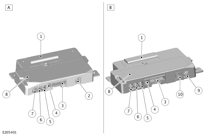
| ITEM | DESCRIPTION |
|---|---|
| A | Vehicles with InControl Touch audio system |
| B | Vehicles with InControl Touch Pro audio system |
| 1 | Back-up Battery cover |
| 2 | Universal Serial Bus (USB) connector |
| 3 | Electrical connector |
| 4 | Speaker connector |
| 5 | Global System for Mobile communications (GSM) antenna connector |
| 6 | Global Positioning System (GPS) antenna connector |
| 7 | Global System for Mobile communications (GSM) antenna connector |
| 8 | Telematics Control Module (TCU) |
| 9 | WiFi client connection |
| 10 | BroadR-Reach® Ethernet connector |
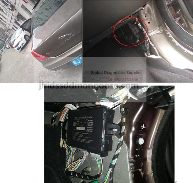
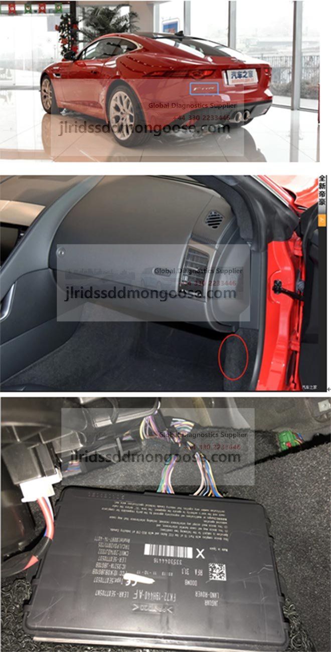
The Telematics Control Module (TCU) is located on the left wheel arch, behind the rear seat bolster trim panel.
The TCU receives a permanent power supply from the startup battery via fuses in the Battery Junction Box (BJB) and the Rear Junction Box (RJB).
The TCU controls the telematics system by communicating with the vehicle systems. The TCU uses the High Speed (HS) Controller Area Network (CAN) power mode zero systems bus via the Body Control Module/Gateway Module (BCM/GWM) assembly.
The system transmits/receives signals via:
- The Global Navigation Satellite System (GNSS)
- The Global System for Mobile communications (GSM).
Depending on vehicle specification, the TCU also transmits/receives signal from the following:
- The portable audio interface panel via Universal Serial Bus (USB) connection, if the vehicle is equipped with InControl Touch audio system with WiFi Hotspot feature.
- The roof pod via co-axial connection, on vehicles with InControl Touch Pro audio system with ‘InControl Pro Services’.
The TCU has an integral embedded Subscriber Identification Module (SIM) card. The embedded SIM card is part of the module circuitry and cannot be removed. The embedded SIM card is configured to enable the network to retrieve and pass information to the telematics service provider. The embedded SIM card enables the telematics service provider to call back the TCU, if required.
The embedded SIM card is used in the following circumstances:
- During an Emergency Call (eCall)
- During a Breakdown Call (bCall)
- During a stolen vehicle tracking operation.
Use of the embedded SIM card will override the user provided Micro SIM card data transmissions.
This will result in loss of InControl Pro Services during the call duration.
The Restraints Control Module (RCM) is connected directly to the TCU. The hardwired connection provides an instant crash signal communication from the RCM in the event of an accident of a severity to activate the airbags. When the TCU receives the crash signal an automatic eCall is initiated. For additional information, refer to: Airbag Supplementary Restraint System (501-20B Supplementary Restraint System, Description and Operation).
TELEMATICS CONTROL MODULE BACK-UP BATTERY
The back-up battery is integrated into the Telematics Control Module (TCU). The back-up battery is located below a cover which is retained by a screw. The back-up battery contains a single cell that is fully rechargeable.
The back-up battery enables continued operation in the event of a vehicle main power source disconnection, for example:
- In a major accident, or
- In the case of deliberate action of a thief as part of a vehicle theft attempt.
The back-up battery in the TCU will only be active during an Emergency call (eCall), Breakdown call (bCall) or 'Stolen Vehicle Tracking' session in which the vehicle power supply is disabled. The back-up battery is also required for the Jaguar logistics tracking system when the vehicle is in transit mode.
The ignition off mode may occur before the TCU has sent all of its logistics tracking data to the manufacturer servers. The back-up battery enables the TCU to reliably deliver this data. The TCU is in a pre-activated state when in transit mode.
During the vehicle Pre-Delivery Inspection (PDI) process the TCU is removed from transit mode and switched on to an 'activated state'. When the TCU is removed from transit mode, the telematics system on the vehicle becomes fully active.
The TCU charges the back-up battery when the engine is running. The charging function is controlled and regulated by the TCU software.
PORTABLE AUDIO INTERFACE PANEL - VEHICLES WITH INCONTROL TOUCH AUDIO SYSTEM
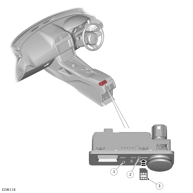
| ITEM | DESCRIPTION |
|---|---|
| 1 | Portable audio interface panel |
| 2 | Subscriber Identification Module (SIM) card reader |
| 3 | Micro Subscriber Identification Module (SIM) card |
The portable audio interface panel is located in the floor console stowage compartment.
If the vehicle is equipped with WiFi Hotspot feature, the portable audio interface panel incorporates a Subscriber Identification Module (SIM) card reader. The SIM card reader utilizes a Micro SIM interface.
The Micro SIM card reader is connected directly to the Telematics Control Module (TCU) via the Universal Serial Bus (USB) connection. The Micro SIM card reader is used to establish the InControl Wi-Fi Hotspot feature. The data-enabled Micro SIM card allows the system to register to a cellular network. The user chooses the network provider by bringing their own Micro SIM card.
The Micro SIM card is placed in the portable audio interface panel. If the SIM card is a different size, a replacement Micro SIM card is required. It is advised that only Micro SIM cards are used. The use of Micro SIM card adaptors are not recommended.
To install the Micro SIM card, insert the Micro SIM card into the portable audio interface panel slot.
NOTE:
If the SIM card has been previously used in a mobile phone or other device and a Personal Identification Number (PIN) has been set, the PIN must be removed before use in the vehicle.
Insert the Micro SIM card with the contacts facing up and the shortest end inwards. The Micro SIM card should not be protruding once correctly inserted. Make sure that the Micro SIM card is located correctly in the SIM card reader. Failure to do so may damage the Micro SIM card or the SIM card reader.
To remove the Micro SIM card, gently push in and release.
PORTABLE MEDIA INTERFACE PANEL - VEHICLES WITH INCONTROL TOUCH PRO AUDIO SYSTEM
| ITEM | DESCRIPTION |
|---|---|
| 1 | Portable media interface panel |
| 2 | Subscriber Identification Module (SIM) card reader |
| 3 | Micro Subscriber Identification Module (SIM) card |
The portable media interface panel is located in the floor console stowage compartment.
The portable media interface panel incorporates a Subscriber Identification Module (SIM) card reader. The SIM card reader utilizes a Micro SIM interface.
The Micro SIM card reader is connected directly to the Telematics Control Module (TCU) via the Universal Serial Bus (USB) connection. The Micro SIM card reader is used to establish the InControl Pro Services feature. The users Micro SIM card enables the system to register to a network of personal choice.
The Micro SIM card is placed in the portable media interface panel. If the SIM card is a different size, a replacement Micro SIM card is required. It is advised that only Micro SIM cards are used. The use of Micro SIM card adaptors are not recommended.
To install a Micro SIM card, insert the Micro SIM card into the portable media interface panel slot.
NOTE:
If the SIM card has been previously used in a mobile phone or other device and a Personal Identification Number (PIN) has been set, the PIN must be removed before use in the vehicle.
The Micro SIM card must be inserted with the contacts facing up and the shortest end facing outwards. The Micro SIM card should not be protruding once correctly inserted. Make sure the Micro SIM card is located correctly in the SIM card reader. Failure to do so may damage the Micro SIM card or the SIM card reader.
To remove the Micro SIM card, gently push in and release.
FRONT OVERHEAD CONSOLE
NOTE:
If a vehicle is not fitted with an overhead console but still has InControl Pro Services enabled, please contact the technical support team for troubleshooting, diagnosis and further information. Selected markets have limited telematics features.
| ITEM | DESCRIPTION |
|---|---|
| 1 | Breakdown call (bCall) switch |
| 2 | Microphone |
| 3 | Emergency call (eCall) switch |
The front overhead console houses the Breakdown call (bCall) and Emergency call (eCall) switches and microphone. The functions of the bCall and eCall switches are controlled by the Telematics Control Module (TCU).
The microphone is connected directly to the TCU. The TCU use this connection during an eCall or bCall, enabling the driver to verbally communicate with the telematics service provider.
The location of the microphone changes depending if the vehicle is Left Hand Drive (LHD) or Right Hand Drive (RHD).
The microphone input is shared for voice control by the following:
- The Audio Head Unit (AHU) on vehicles with InControl Touch audio system.
- The Infotainment Master Controller (IMC) on vehicles with InControl Touch Pro audio system.
When the microphone must be used by the AHU or the IMC (depending on specification), the TCU transmits the microphone signals to the AHU or the IMC via hardwired connection.
On vehicles without telematics feature, the microphone is connected directly to the AHU or the IMC (depending on specification).For additional information, refer to: Voice Control (415-01A Information and Entertainment System - Vehicles With: InControl Touch, Description and Operation).
EMERGENCY CALL AND BREAKDOWN CALL SWITCHES
| ITEM | DESCRIPTION |
|---|---|
| A | Light Emitting Diode (LED) indicator off |
| B | Breakdown call (bCall) - LED indicator illuminated - Blue color |
| C | Emergency call (eCall) - LED indicator illuminated - Red color |
| 1 | State 1 |
| 2 | State 2 |
| 3 | State 3 |
| 4 | State 4 |
| 5 | Breakdown call (bCall) switch |
| 6 | Emergency call (eCall) switch |
Light Emitting Diode (LED) indicators, integrated into the Emergency call (eCall) and Breakdown call (bCall) switches, provide switch illumination and indicate the status of the call operation.
The LED indicator sequences of the eCall and bCall switches can identify the current activation status of the following services:
- 'InControl Protect'
- 'InControl Remote' mobile phone application
- 'Secure Tracker’ (where applicable)
- WiFi Hotspot.
The TCU controls the output to the telematics speaker located in the top of the instrument panel.
The LED indicator sequences denote the activation status:
State 1
The High Speed (HS) Controller Area Network (CAN) bus is awake or the engine is running but neither of the LED lamps are illuminated.
The vehicle has not gone through a Pre-Delivery Inspection (PDI).
InControl Protect, InControl Remote mobile phone application and ‘Secure Tracker’ cannot be activated until the PDI is complete.
State 2
The bCall switch is not illuminated.
The HS CAN bus is awake or the engine is running.
The eCall switch is illuminated in red color.
The vehicle PDI is completed, InControl Protect, InControl Remote mobile phone application and ‘Secure Tracker’ are ready for activation.
State 3
NOTE:
For China only, after a PDI the e-Call switch will not be illuminated until activation is completed.
The HS CAN bus is awake or the engine is running.
The eCall switch is illuminated in red color, the bCall switch is illuminated in blue color.
InControl Protect, InControl Remote mobile phone application and ‘Secure Tracker’ activation completed and is linked to a user account.
State 4
The HS CAN bus is awake or the engine is running.
The eCall switch is illuminated in red color.
The b-Call switch is not illuminated (post activation).
The user account has been de-registered from the vehicle. The account can now be connected to a different user.
GLOBAL POSITIONING SYSTEM SIGNAL SPLITTER

The Global Positioning System (GPS) signal splitter is located in the rear left side of the luggage compartment.
The GPS signal splitter shares the Global Navigation Satellite System (GNSS) signals from the roof pod antenna with the following:
- The Telematics Control Module (TCU)
- The Audio Head Unit (AHU) on vehicles with InControl Touch audio system
- The Infotainment Master Controller (IMC) on vehicles with InControl Touch Pro audio system.
ANTENNA
The roof pod is located towards the rear of the roof panel.
The roof pod comprises antennas for the reception of Global Navigation Satellite System (GNSS) signals, Global System for Mobile communications (GSM) signals and external WiFi.
Depending on vehicle specifications, the roof pod can also contain antennas for the following:
- Digital radio signal reception on all markets, except North American Specification (NAS) market vehicles.
- Satellite Digital Audio Radio Service (SDARS) signal reception on NAS market vehicles.
For additional information, refer to: Antenna (415-01A Information and Entertainment System - Vehicles With: InControl Touch, Description and Operation).
OPERATION
The Telematics Control Module (TCU) receives the Global System for Mobile communications (GSM) and Global Navigation Satellite System (GNSS) signals. Signal reception is via the roof pod which contains the GSM and Global Positioning System (GPS) antennas.
Schematic Diagram - Global Navigation Satellite System Signal Flow
| ITEM | DESCRIPTION |
|---|---|
| A | Global Navigation Satellite System (GNSS) signal |
| B | Global System for Mobile communications (GSM) signal |
| 1 | Roof pod - Global Positioning System (GPS)/GSM antenna |
| 2 | Telematics Control Module (TCU) |
| 3 | Infotainment Master Controller (IMC) |
| 4 | Audio Head Unit (AHU) |
| 5 | Global Positioning System (GPS) signal splitter |
The signal from the Global Positioning System (GPS) antenna is passed to the GPS signal splitter via a co-axial cable.
The GPS signal is then passed to the Audio Head Unit (AHU) or the Infotainment Master Controller (IMC) for use by the navigation system. The GPS signal is also passed to the TCU for use by the telematics system.
The GSM signal is received by the roof pod antenna. The signal is passed by a co-axial cable directly to the TCU. In the event of a malfunction of the roof pod antenna, a backup GSM antenna within the TCU will also receive the GSM signal.
The GSM signal, provided by the cellular network operator, enables the TCU to communicate with the telematics service provider. The telematics service provider provides secure mobile data connection and coordinates the sending and receiving of vehicle data and control commands.
The Jaguar InControl system provides two main services: Telematics and Connectivity.
The Jaguar InControl system includes the following Telematics services:
- InControl Protect - Breakdown call (bCall)
- InControl Protect - Emergency call (eCall)
- ‘Secure Tracker’ - Stolen vehicle tracking (where applicable).
The Jaguar InControl system includes the following Connectivity services:
- 'InControl Remote' mobile phone applications with remote vehicle status/operation functions
- InControl Pro Services
- WiFi Hotspot.
Several telematics service providers are integral to the InControl system. In each market emergency response, roadside assistance and stolen vehicle tracking (where applicable) suppliers are integrated with InControl to provide the appropriate services.
The 'InControl Remote' mobile phone application and the 'My Jaguar InControl' website are available to provide an intuitive and secure interface for InControl users. An administration website is available for retailers to set up and manage customer accounts with the 'InControl Admin Website'.
The TCU receives the following inputs:
- Hardwired and High Speed (HS) Controller Area Network (CAN) chassis systems bus crash signal from the Restraints Control Module (RCM). This signal initiates an automatic e-Call activation.
- Hardwired eCall and bCall switch activation signals.
- Hardwired microphone signal.
- Global System for Mobile communication (GSM) and Global Navigation Satellite System (GNSS) signals from the roof pod.
- Internal GSM antenna signals.
On vehicles without the InControl Touch Pro with surround sound 17 speaker system the TCU provides an output directly to the telematics speaker in the instrument panel for eCall.
On vehicles with the InControl Touch Pro with surround sound 17 speaker system the co-axial speaker in the instrument panel is shared between the telematics and audio systems. The co-axial speaker is connected directly to the TCU, which provides signal output for eCall.
When the co-axial speaker is used by the audio system, the Audio Amplifier Module (AAM) provides the audio signal for the co-axial speaker through the TCU.
The TCU communicates with the other vehicle systems on the High Speed (HS) Controller Area Network (CAN) power mode zero systems bus. The Body Control Module/Gateway Module (BCM/GWM) assembly provides the connection to the other vehicle systems to enable remote vehicle feature functions.
TELEMATICS SYSTEM MESSAGES
If there is any fault with the telematics system, the following messages are displayed on the Instrument Cluster (IC) message center:
- 'SOS System Limited' - Displayed if call is possible but with limited service. For example, if there is any fault with the microphone or the speaker (Diagnostic Trouble Code (DTC) present) or the back-up battery is depleted but the call can be placed and vehicle data transmitted.
- 'SOS System Not Available' - Displayed if Telematics Control Module (TCU) is unable to attempt a call. For example, if no network available or TCU has no Controller Area Network (CAN) network connectivity.
A DTC is set in the TCU in the event of 'SOS System Limited'.
SOS System Limited
This message is driven by DTCs, relating to hardware issues:
- External Global System for Mobile communication (GSM) antenna connection failure
- Global Positioning System (GPS) antenna connection failure
- Emergency call (eCall) switch connection failure
- Hardwired connection failure with Restraints Control Module (RCM)
- Microphone connection failure
- Global Navigation Satellite System (GNSS) signal receiver failure, TCU internal failure
- Speaker connection failure
- TCU back-up battery depleted.
SOS System Not Available
This message is driven by four possible scenarios:
- The TCU is disconnected or unresponsive
- Failed Emergency call (eCall) due to no cellular network coverage
- Failed eCall due to no eCall number provisioned
- Modem failure.
SERVICE MODE
NOTE:
Only on vehicles with InControl Secure Tracker feature.
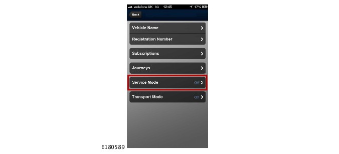
Before disconnecting power to the Telematics Control Module (TCU), for example disconnecting the startup battery to carry out maintenance repairs, the vehicle owner must place the TCU into Service Mode.
If the disconnection procedure is not carried out, the system will send a theft alert to the following:
- The user via the InControl Remote mobile phone application
- The telematics service provider.
Then the system will enter 'Theft Notification' or 'Stolen Vehicle Tracking' mode during which time the charge in the TCU back-up battery would be used. The emergency services may be falsely alerted that the vehicle has been stolen.
For security purposes Service Mode enabling is the sole responsibility of the vehicle owner as it requires a personal identification number that has been defined by the customer.
During vehicle maintenance, where the startup battery is disconnected for a period of time exceeding the 10 hour window, the vehicle owner must re-activate the Service Mode. (To re-activate the Service Mode the vehicle owner is required to use 'InControl Remote' mobile phone application.)
TRANSPORT MODE
NOTE:
Only on vehicles with InControl Secure Tracker feature.
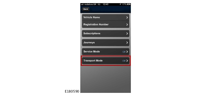
The Telematics Control Module (TCU) contains a motion sensor which is used for vehicle movement detection as part of the stolen vehicle tracking system. Prior to transporting the vehicle, for example a ferry journey, the vehicle owner must place the TCU into Transport Mode to disable the motion sensor.
The 'Theft Notification' function will be activated if vehicle movement is detected when:
- The motion sensor is not disabled
- The ignition is switched off
- The vehicle is locked
- The alarm system is armed (power mode 0)
- And vehicle movement is detected.
As with Service Mode, Transport Mode is the sole responsibility of the vehicle owner for security reasons.
The motion sensor is capable of detecting slow movement, for example jacking the vehicle to remove a road wheel, or winching onto a transporter.
Triggering of the sensor does not immediately generate a 'Theft Notification', but it will activate the Global Positioning System (GPS) receiver and measure the vehicle's movement. If the vehicle moves more than a predefined distance (approximately 200 meters (0.12 miles)) the TCU sends a theft alert to the telematics service provider.
The telematics service provider contacts the vehicle owner to determine if a genuine theft has taken place. If a vehicle theft is confirmed the service provider initiates full GPS tracking of the vehicle.
The Transport Mode disables the movement assessment by the GPS that follows a motion detection, therefore no 'Theft Notification' will be sent to the telematics service provider. Should transporting the vehicle exceed the 10 hour window it is the responsibility of the vehicle owner to reset Transport Mode to avoid a false theft notification being generated.
When the vehicle is locked and the alarm system is armed (power mode 0) and the vehicle network buses are 'asleep', the TCU is still active. This enables movement detection to identify if there is an illegal attempt to move the vehicle. The TCU has a permanent power supply to enable this function. The drain on the startup battery is minimal and the vehicle remains well within its quiescent drain target.
The TCU is linked to the engine immobilization circuit. When a start request is made, the Body Control Module/Gateway Module (BCM/GWM) assembly requests the TCU to pass a secure identification. The signal is passed by the High Speed (HS) Controller Area Network (CAN) power mode zero systems bus. If the identification matches the one in the BCM/GWM assembly, the start request is authorised.
In the event of disconnection or failure of the Global System for Mobile communications (GSM) antennas, resulting in the loss of the GSM signal, an internal antenna is integrated into the TCU. The internal antenna is used as a backup GSM antenna. The backup GSM antenna is used to re-establish communication with the telematics service provider.
CONTROL DIAGRAM
CONTROL DIAGRAM - VEHICLES WITH INCONTROL TOUCH AUDIO SYSTEMS
A = HARDWIRED: T = CO-AXIAL: AT = UNIVERSAL SERIAL BUS (USB): AU = AUTOMOTIVE PIXEL LINK 2 (APIX2): AM = HIGH SPEED (HS) CONTROLLER AREA NETWORK (CAN) CHASSIS SYSTEMS BUS: AX = FLEXRAY SYSTEMS BUS: AY = HIGH SPEED (HS) CONTROLLER AREA NETWORK (CAN) POWER MODE ZERO SYSTEMS BUS: AV = HIGH SPEED (HS) CONTROLLER AREA NETWORK (CAN) COMFORT SYSTEMS BUS.
| ITEM | DESCRIPTION |
|---|---|
| 1 | Telematics Control Module (TCU) |
| 2 | Powertrain Control Module (PCM) |
| 3 | Body Control Module/Gateway Module (BCM/GWM) assembly |
| 4 | Audio Head Unit (AHU) |
| 5 | Restraints Control Module (RCM) |
| 6 | Telematics speaker |
| 7 | Microphone signal |
| 8 | WiFi signal - TCU internal antenna |
| 9 | Global System for Mobile communications (GSM) back-up signal - TCU internal antenna |
| 10 | Roof pod - WiFi signal |
| 11 | Ground |
| 12 | Power supply |
| 13 | Roof pod |
| 14 | Global Positioning System (GPS) signal splitter |
| 15 | Audio Amplifier Module (AAM) |
| 16 | Portable audio interface panel |
| 17 | Microphone |
| 18 | Breakdown call (bCall) switch |
| 19 | Emergency call (eCall) switch |
| 20 | Restraints Control Module (RCM) - Crash signal |
CONTROL DIAGRAM - VEHICLES WITH INCONTROL TOUCH PRO AUDIO SYSTEMS
A = HARDWIRED: T = CO-AXIAL: AT = UNIVERSAL SERIAL BUS (USB): AW = BROADR-REACH® ETHERNET: AU = AUTOMOTIVE PIXEL LINK 2 (APIX2): AM = HIGH SPEED (HS) CONTROLLER AREA NETWORK (CAN) CHASSIS SYSTEMS BUS: AX = FLEXRAY SYSTEMS BUS: AY = HIGH SPEED (HS) CONTROLLER AREA NETWORK (CAN) POWER MODE ZERO SYSTEMS BUS.
| ITEM | DESCRIPTION |
|---|---|
| 1 | Telematics Control Module (TCU) |
| 2 | Powertrain Control Module (PCM) |
| 3 | Body Control Module/Gateway Module (BCM/GWM) assembly |
| 4 | Restraints Control Module (RCM) |
| 5 | Telematics speaker |
| 6 | Co-axial speaker - Vehicles with InControl Touch Pro with surround sound 17 speaker audio system |
| 7 | Microphone signal |
| 8 | Infotainment Master Controller (IMC) |
| 9 | WiFi signal - TCU internal antenna |
| 10 | Global System for Mobile communications (GSM) back-up signal - TCU internal antenna |
| 11 | Roof pod - WiFi signal |
| 12 | Ground |
| 13 | Power supply |
| 14 | Roof pod |
| 15 | Global Positioning System (GPS) signal splitter |
| 16 | Audio Amplifier Module (AAM) |
| 17 | Portable media interface panel |
| 18 | Microphone |
| 19 | Breakdown call (bCall) switch |
| 20 | Emergency call (eCall) switch |
| 21 | Restraints Control Module (RCM) - Crash signal |