WSM-53145 - Workshop manual Defender (LE) 2023 AIRBAG SUPPLEMENTARY RESTRAINT SYSTEM PART NO: LR154987 Eng. PN M9V214D374AB
AIRBAG SUPPLEMENTARY RESTRAINT SYSTEM (G2424832)
DIAGNOSIS AND TESTING
PRINCIPLE OF OPERATION
For a detailed description of the supplemental restraints system and operation, refer to the relevant Description and Operation section in the workshop manual. REFER to: Airbag Supplementary Restraint System - [+] 5 Seat Configuration/[+] 7 Seat Configuration (501-20B Supplementary Restraint System, Description and Operation).
SAFETY INFORMATION
WARNINGS:
- TO AVOID ACCIDENTAL DEPLOYMENT AND POSSIBLE PERSONAL INJURY, THE BACKUP POWER SUPPLY MUST BE DEPLETED BEFORE REPAIRING OR REPLACING ANY AIRBAG SUPPLEMENTAL RESTRAINT SYSTEM COMPONENTS. TO DEPLETE THE BACKUP POWER SUPPLY ENERGY, DISCONNECT THE BATTERY GROUND CABLE AND WAIT ONE MINUTE. FAILURE TO FOLLOW THIS INSTRUCTION MAY RESULT IN PERSONAL INJURY
- Do not use a multimeter to probe the restraints control module. It is possible for the power from the meter battery to trigger the activation of the airbags. Failure to follow this instruction may result in personal injury
NOTE:
It is advisable not to use a mobile phone or to have a mobile phone in close proximity when working on the restraints control module or associated systems
Power Supply Depletion
Before beginning any work on the restraints control module/supplemental restraints system or related components:
- Remove the ignition key
- Disconnect the battery leads, ground first
- Wait 1 minute for the power circuit to discharge
There are comprehensive instructions on the correct procedures for supplemental restraints system repairs in the manual. Refer to the relevant section of the workshop manual
INSPECTION AND VERIFICATION
CAUTION:
Diagnosis by substitution from a donor vehicle is NOT acceptable. Substitution of control modules does not guarantee confirmation of a fault, and may also cause additional faults in the vehicle being tested and/or the donor vehicle
NOTES:
- If the control module or a component is at fault and the vehicle remains under manufacturer warranty, refer to the warranty policy and procedures manual (section B1.2), or determine if any prior approval program is in operation, prior to the installation of a new module/component
- Check and rectify basic faults before beginning diagnostic routines involving pinpoint tests
- Verify the customer concern
- Confirm the function of the warning lamp (if the warning lamp is inoperative, system faults will be signalled by an audible chime)
- Visually inspect for obvious signs of damage and system integrity
Visual Inspection
| MECHANICAL | ELECTRICAL |
|---|---|
|
|
- If an obvious cause for an observed or reported concern is found, correct the cause (if possible) before proceeding to the next step.
SYMPTOM CHART
| SYMPTOM | POSSIBLE CAUSES | ACTION |
|---|---|---|
|
| NOTE:
Damage caused by an incorrect removal or installation procedure is not warrantable.
|
|
|
|
|
| |
|
|
- If the cause is not visually evident, verify the symptom and refer to the Symptom Chart, alternatively check for Diagnostic Trouble Codes and refer to the DTC Index
- Check JLR claims submission system for open campaigns. Refer to the corresponding bulletins and SSMs which may be valid for the specific customer complaint and complete the recommendations as required.
- When installing or checking the SRS with AK2 connectors the locking plunger must be engaged
SUPPLEMENTAL RESTRAINTS SYSTEM AK2 TYPE CONNECTORS
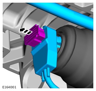
- Incorrect Position (Disengaged)
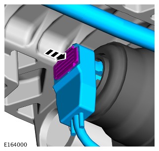
- Correct Position (Engaged)
Seatbelt Buckle Pre Tensioner Diagnostics
This procedure should be used to aid diagnosis of the following SRS - buckle pre tensioner (PBP) fault codes
| SRS LIGHT STATUS | DTC |
|---|---|
| On | B1211-11, B1211-12, B1211-13, B1211-2B |
| On | B1214-11, B1214-12, B1214-13, B1214-2B |
| PINPOINT TEST A : BUCKLE/RETRACTOR PRE TENSIONER DIAGNOSTIC | |
|---|---|
| A1: DIAGNOSTIC PROCEDURE | |
| TEST CONDITIONS | DETAILS/RESULTS/ACTIONS |
WARNINGS:
| |
| 1 Check location of harness fly-lead making sure there is no risk snagging and sufficient strain relief during full seat travel | |
| 2 Disconnect under-seat buckle pre tensioner connectors | |
| 3 Check connector for water ingress or signs of corrosion (white/green residue) | |
| 4 Check for debris in female connector and remove as required | |
| 5 Check for debris in male harness end connector and remove | |
| 6 Check that male connector pins are secure and in good condition | |
| 7 Check that all connector terminals are clean secure and in good condition | |
8
Reconnect the connector
| |
| 9 Check actuator harness fly-lead is connected and correctly routed | |
| 10 Reconnect the vehicle battery | |
| 11 Clear the DTC, cycle the ignition state off / on wait 30 seconds and re-test | |
12
To confirm repair. When sitting in seat, retest as follows:
| |
| Is the warning lamp illuminated? Yes GO to Pinpoint Test B. No No further action required | |
| PINPOINT TEST B : BUCKLE/RETRACTOR PRE TENSIONER DIAGNOSTIC | |
|---|---|
| B1: DIAGNOSTIC PROCEDURE | |
| TEST CONDITIONS | DETAILS/RESULTS/ACTIONS |
WARNINGS:
| |
| 1 Check routing and condition of harness along buckle pre tensioner tube | |
| 2 Make sure harness is in good condition with no damage | |
| 3 Make sure harness is securely routed | |
| 4 Reconnect the vehicle battery | |
| 5 Clear the DTC, cycle the ignition state off / on wait 30 seconds and re-test | |
6
To confirm repair. When sitting in seat, retest as follows:
| |
| Is the warning lamp illuminated? Yes GO to Pinpoint Test C. No No further action required | |
| PINPOINT TEST C : BUCKLE/RETRACTOR PRETENSIONER DIAGNOSTIC | |
|---|---|
| C1: DIAGNOSTIC PROCEDURE | |
| TEST CONDITIONS | DETAILS/RESULTS/ACTIONS |
WARNINGS:
| |
| 1 Remove seat and check routing and condition of under-seat harness | |
| 2 Make sure harness is in good condition with no damage | |
| 3 Make sure harness is securely routed | |
| 4 Make sure all fir tree clips and cable ties are correctly installed | |
| 5 Reinstall seat | |
| 6 Make sure harness is securely routed | |
| 7 Reconnect the vehicle battery | |
| 8 Clear the DTC, cycle the ignition state off / on wait 30 seconds and re-test | |
9
To confirm repair. When sitting in seat, retest as follows:
| |
| Is the warning lamp illuminated? Yes Install new component No No further action required | |
PINPOINT TESTS
| PINPOINT TEST D : INCORRECT ELECTRICAL CONNECTION AT SIDE AIRBAG MODULE | |
|---|---|
| D1: LOCKING PLUNGER NOT ENGAGED | |
| TEST CONDITIONS | DETAILS/RESULTS/ACTIONS |
| 1 Visually inspect the condition of the electrical connector to the side airbag module | |
| 2 Inspect the locking plunger of the electrical connector and push firmly into place if the plunger is not flush with the top of the connector | |
| 3 Using the Jaguar Land Rover approved diagnostic equipment, clear the DTCs and retest | |
| Has the DTC cleared? Yes No further action required No GO to Pinpoint Test E. |
PINPOINT TESTS
| PINPOINT TEST E : DAMAGED/CHAFED/TRAPPED HARNESS | |
|---|---|
| E1: DAMAGED HARNESS | |
| TEST CONDITIONS | DETAILS/RESULTS/ACTIONS |
| 1 Visually inspect the condition of the seat wiring harness from the side airbag module connector through the seat to the under seat connection | |
| 2 Inspect the seat wiring harness for evidence of chafing, trapping, compression of the wire, repair as required | |
| 3 Using the Jaguar Land Rover approved diagnostic equipment, clear the DTCs and retest | |
| Has the DTC cleared? Yes No further action required No GO to Pinpoint Test G. |
PINPOINT TESTS
| PINPOINT TEST F : INCORRECT ELECTRICAL CONNECTION UNDER THE SEAT | |
|---|---|
| F1: SEAT HARNESS CONNECTOR | |
| TEST CONDITIONS | DETAILS/RESULTS/ACTIONS |
| 1 Visually inspect the condition of the under seat wiring harness electrical connection at the seat harness to the main harness connector | |
| 2 Disconnect the connector, check for backed out pins/damage/corrosion (repair as required), reconnect making sure the male to female mating is firmly in place | |
| 3 Using the Jaguar Land Rover approved diagnostic equipment, clear the DTCs and retest | |
| Has the DTC cleared? Yes No further action required No GO to Pinpoint Test G. |
PINPOINT TESTS
AIRBAG WARNING LIGHT ON AND DIAGNOSTIC TROUBLE CODES (DTC(S)) B0001-13 SET
| PART DESCRIPTION | PART NUMBER |
|---|---|
| Nyogel 760G | LR054614 |
If the airbag warning light is on with DTC(s) B0001-13 set, follow the steps below.
- Using the Jaguar Land Rover approved diagnostic equipment, check, and update the Restraints Control Module (RCM) with the latest level of software. Clear the DTC(s) and retest
- Turn on the ignition, check the airbag warning light disappears. Observe the instrument cluster for at least 15 seconds to make sure the airbag warning light does not re-appear. Using the Jaguar Land Rover approved diagnostic equipment, check B0001-13 has not returned
- Remove the driver airbag from the steering wheel
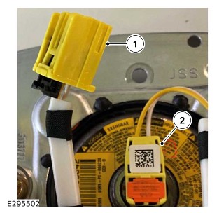
NOTE:
DO NOT disconnect the driver airbag connector from the driver airbag (Connector number 2 as shown in the image above)
- Disconnect the driver airbag connector from the clockspring (Connector number one as shown in the image above)

NOTES:
- No more than 0.2g is to applied to the connector, 0.1g per pin
- Pins 1 and 2 of the driver airbag connector are highlighted on the circuit diagram image above for clarity
- Apply Nyogel 760G to the connector pins
- Install the driver airbag to the steering wheel
- Using the Jaguar Land Rover approved diagnostic equipment, clear the DTC(s) and retest
- If the fault persists or the vehicle has been returned with repeat symptoms, install a new clockspring and driver airbag making sure to apply Nyogel as noted in step 3
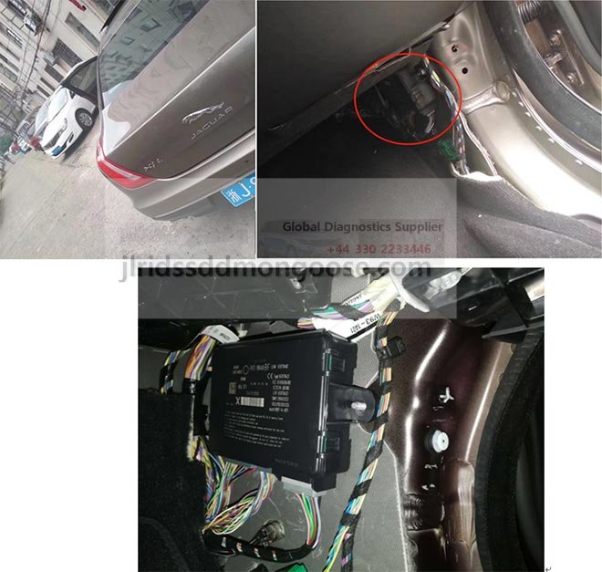
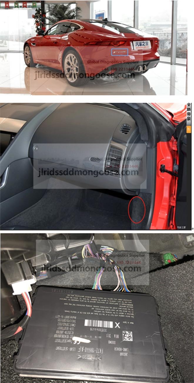
OCCUPANT CLASSIFICATION SENSOR CONTROL MODULE (OCSCM)
Seat Position Sensor – Essential Notes On Removal / Replacement
NOTE:
The seat position sensor, a hall-effect sensor, is installed to the underside of the passenger-side seat only on NAS vehicles. It should be noted that these sensors cannot be re-installed when removed. If any work is undertaken that requires removal of the seat position sensor, a NEW sensor MUST be installed. Make sure the correct replacement parts are installed.
The OCSCM incorporates 3 load statuses for the seat cushion:
- When the load is less than the lower limit, the seat is classified as unoccupied.
- When the load exceeds the lower limit, but is less than the upper limit, the seat is classified as occupied by a small person or a child restraint is being used.
- When the upper limit is exceeded, the seat is classified as occupied by an adult.
The occupant classification system has four possible states as detailed in the following table:
| CLASSIFICATION | SEAT STATUS | PASSENGER AIRBAG STATUS | AIRBAG INDICATOR STATUS |
|---|---|---|---|
| Empty | Empty | Disabled | Off |
| Occupied inhibit | >td rowspan="1">Passenger airbag and passenger side airbag operation is disabled | On | |
| Occupied allow | >td rowspan="1">Passenger airbag and passenger side airbag operation is enabled | Off | |
| Error | - | Passenger airbag and passenger side airbag operation is disabled | On |
OCCUPANT CLASSIFICATION SENSOR CONTROL MODULE (OCSCM) EXISTING MODULE PROGRAMMING
NOTE:
Do not attempt to install individual components from the Occupant Classification Sensor (OCS) service kit, as they are calibrated to function as a single assembly. The complete service kit consists of foam, occupant classification sensor bladder mat with attached smart digital pressure sensor. The Controller Area Network (CAN) type communication and LIN type communication OCS types are NOT interchangeable. Make sure the correct service kit for the vehicle is being used.
- Check the seat and make sure all electrical connectors are secure. Make sure the seat is correctly mounted and fixings are tightened to the correct torque. Refer to workshop manual section REFER to: Front Row Seat - Vehicles With: Power Seats (501-10A Seating - Front Row Seats, Removal and Installation) / Front Row Seat - Vehicles Without: Power Seats (501-10A Seating - Front Row Seats, Removal and Installation).
NOTE:
Make sure the vehicle is stationary and on a level surface. The seat must be secure and in an upright position before performing the next step. Failure to do this could induce a DTC.
- Connect the Jaguar Land Rover approved diagnostic equipment
- Set the ignition to ON and wait 10 seconds. Make sure the SRS warning light is illuminated during the ignition test cycle. The SRS warning light should then extinguish after the 10 seconds to confirm no SRS faults exist
NOTE:
All OCS DTCs will be set in the RCM.
- Wait 5 seconds then set the OCS control module in to security access mode, after going in to an extended diagnostic session
- Using the Jaguar Land Rover approved diagnostic equipment, refer to datalogger signals ECU calibration Data #1 Number (0xF124), ECU Delivery Assembly Number (0xF113), ECU Core Assembly Number (0xF111), ECU Strategy Number (0xF188). Make a note of the OCS control module part number to make sure it is the correct part number for the vehicle
- Using the Jaguar Land Rover approved diagnostic equipment, check and update the OCS control module to the latest level software. Make sure the ignition is set to OFF and wait at least 5 seconds
- Set the ignition to ON and wait at least 125 seconds. This will allow sufficient time for DTCs to log in the RCM if any are present
- Using the Jaguar Land Rover approved diagnostic equipment, check for OCS and Restraints Control Module (RCM) DTCs stored in the RCM. If no DTCs are found and no SRS warning light is illuminated, no further action is necessary. If any DTCs are found and/or the SRS warning light is illuminated, refer to the relevant section of the workshop manual and perform the relevant repair actions as necessary. Re-perform this procedure to confirm the repair
OCCUPANT CLASSIFICATION SENSOR CONTROL MODULE (OCSCM) NEW MODULE REPLACEMENT AND PROGRAMMING
NOTE:
Do not attempt to install individual components from the Occupant Classification Sensor (OCS) service kit, as they are calibrated to function as a single assembly. The complete service kit consists of foam, occupant classification sensor bladder mat with attached smart digital pressure sensor. They MUST NOT be installed separately. To make sure the correct function, it is essential both parts are installed together, as it is a safety critical system.
- Remove the passenger seat from the vehicle. Refer to REFER to: Front Row Seat - Vehicles With: Power Seats (501-10A Seating - Front Row Seats, Removal and Installation) / Front Row Seat - Vehicles Without: Power Seats (501-10A Seating - Front Row Seats, Removal and Installation).
- Install a new OCS service kit to the seat.
- Re-install the seat and make sure all electrical connectors are secure. Make sure the seat is correctly mounted and fixings are tightened to the correct torque. Refer to workshop manual section REFER to: Front Row Seat - Vehicles With: Power Seats (501-10A Seating - Front Row Seats, Removal and Installation) / Front Row Seat - Vehicles Without: Power Seats (501-10A Seating - Front Row Seats, Removal and Installation).
NOTE:
Make sure the vehicle is stationary and on a level surface. The seat must be secure and in an upright position before performing the next step. Failure to do this could induce a DTC.
- Connect the Jaguar Land Rover approved diagnostic equipment, set the ignition to ON and wait 5 seconds for the module to wake up
- Using the Jaguar Land Rover approved diagnostic equipment, refer to datalogger signals ECU calibration Data #1 Number (0xF124), ECU Delivery Assembly Number (0xF113), ECU Core Assembly Number (0xF111), ECU Strategy Number (0xF188). Make a note of the OCS control module part number to make sure it is the correct part number for the vehicle
- Using the Jaguar Land Rover approved diagnostic equipment, check and update the OCS control module to the latest level software. Make sure the ignition is set to OFF and wait at least 7 seconds
- Set the OCS control module in to security access mode, after going in to an extended diagnostic session. Using the Jaguar Land Rover approved diagnostic equipment, check for any OCS control module or Restraints Control Module (RCM) related DTCs. If any DTCs are found, perform a software update
NOTE:
All OCS DTCs will be set in the RCM.
- Set the ignition to OFF and wait 10 seconds
- Set ignition to ON and wait 10 seconds
- Set the OCS control module in to security access mode, after going in to an extended diagnostic session
- Using the Jaguar Land Rover approved diagnostic equipment, perform routine - Learn Seat Occupant Classification Zero Position (0x5007) This will re-calibrate the new OCS control module
- Set the ignition to OFF and wait at least 10 seconds
- Set the ignition to ON and wait 10 seconds. Make sure the SRS warning light is illuminated during the ignition test cycle. The SRS warning light should then extinguish after the 10 seconds to confirm no SRS faults exist
- If the Learn Seat Occupant Classification Zero Position (0x5007) routine passes (09) and no SRS warning light is illuminated, no further action is necessary. If the Learn Seat Occupant Classification Zero Position (0x5007) routine fails and/or the SRS warning light is illuminated, note which process of the routine failed and proceed to step 15
- 02 - Process Failed - Seat Not Calibrated. The Learn Zero position cannot be calibrated if the seat has not been correctly calibrated at the seat manufacturing plant. Install a new service kit as necessary and re perform Learn Seat Occupant Classification Zero Position routine (0x5007)
- 03 - Process Failed - Wait 10 Seconds To Re Zero. Wait 10 seconds after ignition ON and re perform Learn Seat Occupant Classification Zero Position routine (0x5007)
- 04 - Re Zero Failure - DTCs Set. A fault is preventing the Learn Seat Occupant Classification Zero Position routine (0x5007) from completing correctly. Check for DTCs and repair as necessary, then re perform Learn Seat Occupant Classification Zero Position routine (0x5007)
- 06 - Process Failed - OCS Pressure Out Of Range. The seat must be empty to perform the Learn Seat Occupant Classification Zero Position routine (0x5007) correctly. Make sure the seat is empty and re perform Learn Seat Occupant Classification Zero Position routine (0x5007)
- 07 - Process Failed - OCS Pressure Fluctuation. Check to make sure the OCS hose is correctly routed and clipped in position, as this could prevent the Learn Seat Occupant Classification Zero Position routine (0x5007) from completing correctly. Any vibrations or variations within the passenger compartment, for example doors opening / closing will prevent the Learn Seat Occupant Classification Zero Position routine (0x5007) from completing correctly. Make sure the passenger compartment environment is stable and re perform Learn Seat Occupant Classification Zero Position routine (0x5007)
- 08 - Process Failed - Temperature Out Of Range. Make sure the workshop temperature is within normal acceptable working range and re perform Learn Seat Occupant Classification Zero Position routine (0x5007)
- 09 - Process Completed - Re Zero Success. Routine has passed, no further actions necessary
- Using the Jaguar Land Rover approved diagnostic equipment, check for any OCS control module or RCM related DTCs. If any DTCs are found, refer to the relevant section of the workshop manual and perform the relevant repair actions as necessary. Re-perform this procedure to re-calibrate the OCS control module
SEAT POSITION SENSOR - NOTES ON REMOVAL/REPLACEMENT
NOTE:
NAS vehicles have a seat position sensor installed to the passenger-side seat only.
The seat position sensor, a hall-effect sensor, is installed to the underside of the passenger-side seat on NAS vehicles. It should be noted that these sensors cannot be re-installed when removed. If any work is undertaken that requires removal of the seat position sensor, a NEW sensor MUST be installed. Note that different sensors are installed to left and right seats, so care should be taken to make sure the correct replacement parts are installed
RESTRAINTS CONTROL MODULE FLEXRAY COMMUNICATION TABLE
For DTCs U0001-81, U0001-86 and U0001-87: Using the Jaguar Land Rover approved diagnostic equipment, check the snapshot data (0xD020) to determine the missing message source control module. Check the relevant control module for related DTCs and refer to the relevant DTC index. Using the Jaguar Land Rover approved diagnostic equipment, perform a FlexRay network integrity test. Refer to the electrical circuit diagrams and check the Vehicle communication bus F (FlexRay) between the relevant control module (for example as indicated by the snapshot data) and the restraints control module
To decode the Hexadecimal response use the following table
| DATA IDENTIFIER (DID) D020 HEXADECIMAL RESPONSE | MISSING MESSAGE | MISSING MESSAGE SOURCE SYSTEM |
|---|---|---|
| 00BA | VehicleSpeed | Anti-lock Brake System (ABS) |
| 00BF | VehicleSpeedQF | Anti-lock Brake System (ABS) |
| 00C4 | WheelSpeed_FRL | Anti-lock Brake System (ABS) |
| 00C5 | WheelSpeed_FRL_QF | Anti-lock Brake System (ABS) |
| 00C6 | WheelSpeed_FRR | Anti-lock Brake System (ABS) |
| 00C7 | WheelSpeed_FRR_QF | Anti-lock Brake System (ABS) |
| 00C8 | WheelSpeed_REL | Anti-lock Brake System (ABS) |
| 00C9 | WheelSpeed_REL_QF | Anti-lock Brake System (ABS) |
| 00CA | WheelSpeed_RER | Anti-lock Brake System (ABS) |
| 00CB | WheelSpeed_RER_QF | Anti-lock Brake System (ABS) |
| 0124 | AirbagBulbStatus | Gateway Module (GWM) or Instrument Panel Cluster (IPC) through CAN |
| 0147 | AmbientTemp | Powertrain Control Module (PCM) |
| 0148 | AmbientTempQF | Powertrain Control Module (PCM) |
| 01C4 | CarConfigParameters | Gateway Module (GWM) |
DTC INDEX
RESTRAINTS CONTROL MODULE (G2409833)
REMOVAL AND INSTALLATION
- 76.74.06
- ELECTRONIC CONTROL UNIT - (S.R.S) AIR BAG SYSTEM - RENEW
- ALL DERIVATIVES
- 0.20
- USED WITHINS
GENERAL EQUIPMENT
| EQUIPMENT NAME |
|---|
| Jaguar Land Rover approved diagnostic equipment |
REMOVAL
WARNINGS:
- To prevent accidental deployment, you must power down the Restraints Control Module (RCM). Wait at least 1 minute after you disconnect the startup battery ground cable before you do any work on the Supplementary Restraint System (SRS). If you do not follow these instructions, it can cause injury or death.
- Do not probe SRS electrical connectors.
- People working on the SRS must be fully trained and have been issued with the safety guidelines.
NOTES:
- This procedure contains illustrations showing certain components removed to provide extra clarity.
- This procedure contains some variation in the illustrations depending on the vehicle specification, but the essential information is always correct.
The following step(s) applies to:
All vehicles
- Make the SRS safe.Refer to: Supplementary Restraint System Health and Safety Precautions (100-00 General Information, Description and Operation).
- Disconnect the 12 V system.Refer to: 12V System Disconnect and Connect (414-00 Battery and Charging System - General Information, General Procedures).
The following step(s) applies to:
Vehicles with stowage compartment
- Remove the front floor console.Refer to: Floor Console (501-12 Instrument Panel and Console, Removal and Installation).
Remove the 2 carpet fasteners.
- Remove the fastener.
- Remove the heater duct.

The following step(s) applies to:
Vehicles without stowage compartment
- Remove the front floor console.Refer to: Floor Console - Vehicles Without: Stowage Compartment (501-12 Instrument Panel and Console, Removal and Installation).
The following step(s) applies to:
Vehicles with fold flat seat
- Remove the front row center seat.Refer to: Front Row Center Seat (501-10A Seating - Front Row Seats, Removal and Installation).
- Remove the fastener.
- Remove the heater duct.
The following step(s) applies to:
All vehicles
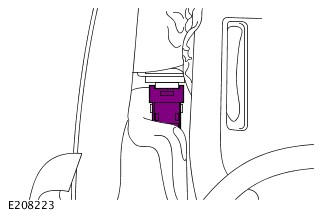
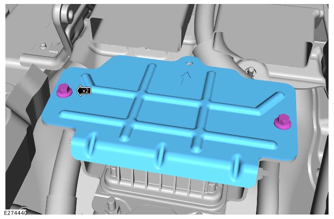
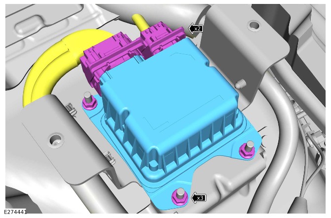
- Remove the 2 bolts.
- Remove the shield.
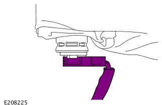
- Disconnect the 2 electrical connectors.
- Remove the 3 nuts.
- Remove the RCM.
INSTALLATION
The following step(s) applies to:
All vehicles
- Install the RCM.
- Install and tighten the 3 nuts.Torque: 11Nm
- Connect the 2 electrical connectors.
- Install the shield.
- Install and tighten the 2 bolts.Torque: 9Nm
The following step(s) applies to:
Vehicles with stowage compartment
- Install the heater duct.
- Install the fastener.
- Install the 2 carpet fasteners.
- Install the front floor console.Refer to: Floor Console (501-12 Instrument Panel and Console, Removal and Installation).
The following step(s) applies to:
Vehicles without stowage compartment
- Install the front floor console.Refer to: Floor Console - Vehicles Without: Stowage Compartment (501-12 Instrument Panel and Console, Removal and Installation).
The following step(s) applies to:
Vehicles with fold flat seat
- Install the heater duct.
- Install the fastener.
- Install the 2 carpet fasteners.
- Install the front row center seat.Refer to: Front Row Center Seat (501-10A Seating - Front Row Seats, Removal and Installation).
The following step(s) applies to:
All vehicles
- Connect the 12 V system.Refer to: 12V System Disconnect and Connect (414-00 Battery and Charging System - General Information, General Procedures).
- If a new component has been installed, configure using the Jaguar Land Rover approved diagnostic equipment. SRO 85.86.42 to be claimed separately.General Equipment: Jaguar Land Rover approved diagnostic equipment
SIDE AIRBAG MODULE (G2344844)
REMOVAL AND INSTALLATION
- 76.74.31
- AIR BAG - SIDE IMPACT - FRONT SEAT - DRIVERS - RENEW
- ALL DERIVATIVES
- 0.60
- USED WITHINS
REMOVAL
WARNINGS:
- To avoid accidental deployment and possible personal injury, the backup power supply must be depleted before repairing or replacing any airbag Supplementary Restraint System (SRS) components. To deplete the backup power supply energy, disconnect the battery ground cable and wait for 1 minute. Failure to follow this instruction may result in personal injury.
- Do not probe the SRS electrical connectors.
NOTE:
- This procedure contains some variation in the illustrations depending on the vehicle specification, but the essential information is always correct.
- This procedure contains illustrations showing certain components removed to provide extra clarity.
- Make the SRS safe.Refer to: Supplementary Restraint System Health and Safety Precautions (100-00 General Information, Description and Operation).
- Remove the front row seat head restraint.Refer to: Front Row Seat Head Restraint (501-10A Seating - Front Row Seats, Removal and Installation).
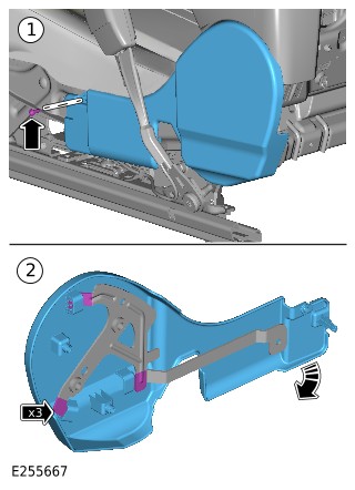
Release the seat backrest cover rear clip.
- Remove the screw.
- Remove the side trim panel in the direction illustrated.
Release the 2 wiring harness clips.
- NOTE:
If equipped.
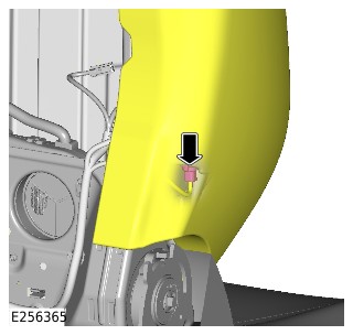
Disconnect the electrical connector from the heater element.
- NOTE:
Repeat the step for the other side.
Release the upper seat cushion tension strap.
Release the 2 lower seat cushion tension straps.
- NOTE:
Repeat the step for the other side.
Release the 4 front row seat backrest clips.
Remove the 2 side airbag nuts.
- Reposition the cushion to get access to the electric connector.
- Disconnect the electrical connector from the side airbag .
Release the 2 blower motor clips.
- CAUTION:
Note the installed position of the component(s) prior to removal.
Remove the side airbag.
INSTALLATION
- WARNING:
Make sure that the airbag is correctly installed in to the seat cushion chute. Failure to follow this instruction may result in incorrect operation of the airbag.
Install the side airbag. - Install the blower motor to the 2 clips.
- Connect the electrical connector to the side airbag.
- Position the cushion in the correct location.
- Install and tighten the 2 side airbag nuts.Torque: 9Nm
- NOTE:
Repeat the step for the other side.
Install the 4 front row seat backrest clips. - Install the 2 lower seat cushion tension straps.
- NOTE:
Repeat the step for the other side.
Install the upper seat cushion tension strap. - NOTE:
If equipped.
Connect the electrical connector to the heater element. - Install the 2 wiring harness clips.
- Install the side trim panel.
- Install and tighten the screw.
- Install the seat backrest cover rear clip.
- Install the front row seat head restraint.Refer to: Front Row Seat Head Restraint (501-10A Seating - Front Row Seats, Removal and Installation).
PTI - CHASSIS AND CHASSIS ATTACHMENTS - INGENIUM I6 3.0L DIESEL (G2894389)
DESCRIPTION AND OPERATION
PTI - ITEM 6 CHASSIS AND CHASSIS ATTACHMENTS
FUEL TANKS AND PIPES - 6.1.3
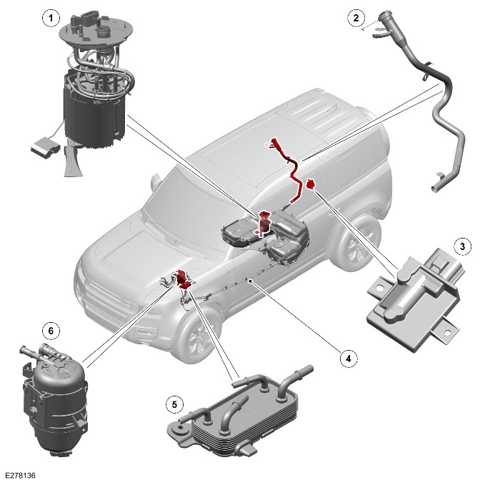
| ITEM | DESCRIPTION |
|---|---|
| 1 | Low Pressure (LP) fuel pump assembly |
| 2 | Fuel filler cap and filler pipe |
| 3 | Fuel Pump Driver Module (FPDM) |
| 4 | Fuel delivery and return lines |
| 5 | Fuel cooler |
| 6 | Fuel filter |
Ingenium I6 3.0L Diesel - Fuel Fired Booster Heater (if equipped)
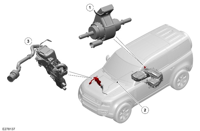
| ITEM | DESCRIPTION |
|---|---|
| 1 | Fuel Fired Booster Heater (FFBH) fuel pump |
| 2 | FFBH delivery line |
| 3 | FFBH |
The fuel lines will be visible if the under trays are removed.
ENGINE PERFORMANCE - 6.1.9
i - Engine Control Unit valid configuration
Connect Jaguar Land Rover (JLR) approved diagnostic equipment to the Diagnostic Connector to check the vehicles Engine Control Unit configuration.
ii - Reading the Calibration Identification Numbers
- Read Data IDentifier (DID) 0xF804 Calibration Identifications
- Read DID 0xF806 Calibration Verification Numbers
- Using Mode/Service $09 - Request Vehicle Information
iv - Valid Calibration Identifications
OBD DID 0xF804 Calibration Identifications should match one of the values in the table below:
| 0x054C384232 | 0x033132364C | 0x013044444C |
v - Software Identification Number
OBD DID 0xF806 Calibration Verification Numbers should appear in the table below:
| 0x05E0850D6B | 0x0365367D5A | 0x03EA2289B0 | 0x0533D389DF |
| 0x031E52A3BA | 0x032F38E191 | 0x0000000062 | 0x039F030F82 |
| 0x0519C910D4 | 0x013A8BD504 | 0x05F5877F3C | |
| 0x00000000 | 0x05BBC2BE4F | 0x05A1DC9D03 |
SEATING - 6.2
COMPONENT LOCATION - SEATING - NOT DRIVER - 6.2.6
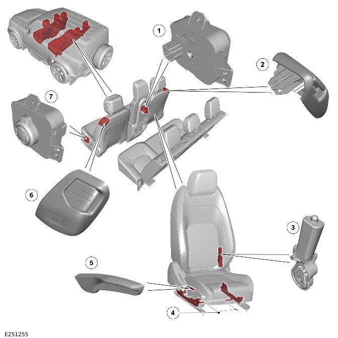
| ITEM | DESCRIPTION |
|---|---|
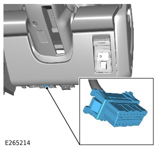
| 1 | Front row seat switchpack - Right |
| 2 | Front row seat exit switch - Right |
| 3 | Front row seat backrest recline motor (quantity 2) |
| 4 | Front row seat forward/rearward adjustment lever (quantity 2) |
| 5 | Front row seat height adjustment lever (quantity 2) |
| 6 | Front row seat exit switch - Left |
| 7 | Front row seat switchpack - Left |
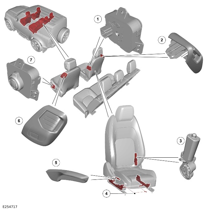
| ITEM | DESCRIPTION |
|---|---|
| 1 | Front row seat switchpack - Right |
| 2 | Front row seat easy entry switch - Right |
| 3 | Front row seat backrest recline motor (quantity 2) |
| 4 | Front row seat forward/rearward adjustment lever (quantity 2) |
| 5 | Front row seat height adjustment lever (quantity 2) |
| 6 | Front row seat easy entry switch - Left |
| 7 | Front row seat switchpack - Left |
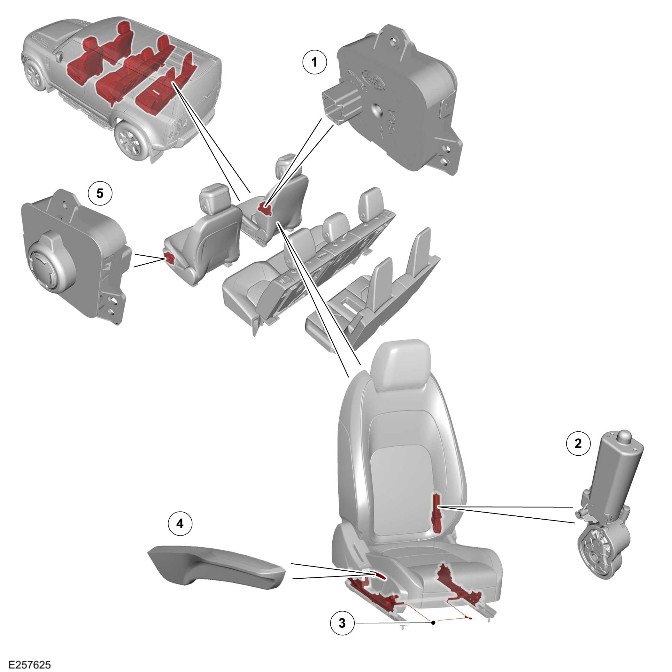
| ITEM | DESCRIPTION |
|---|---|
| 1 | Front row seat switchpack - Right |
| 2 | Front row seat backrest recline motor (quantity 2) |
| 3 | Front row seat forward/rearward adjustment lever (quantity 2) |
| 4 | Front row seat height adjustment lever (quantity 2) |
| 5 | Front row seat switchpack - Left |
OVERVIEW - SEATING NOT DRIVER - 6.2.6
The number of seats installed on this vehicle, excluding the driver is either 1 seat, 2 seats, 3 seats or 4 seats for 3 door models. With 4 seats, 5 seats or 6 seats for 5 door models.
There are no rear facing seats.
INSPECTION - SEATING NOT DRIVER - 6.2.6
The inspection of the seats consists of checking for free movement and security of the fittings.