ANTI-THEFT - PASSIVE
ANTI-THEFT - PASSIVE (G2360324)
Right Hand Drive (RHD) installation shown, Left Hand Drive (LHD) installation is similar.

| ITEM | DESCRIPTION |
|---|---|
| 1 | Body Control Module (BCM)/Gateway Control Module (GWM) |
| 2 | Low Frequency (LF) antenna (quantity 5) |
| 3 | Ignition switch |
| 4 | Immobilizer Antenna Unit (IAU) |
| 5 | Passive entry transceiver (quantity 2) |
| 6 | Remote function receiver |
| 7 | Activity key transceiver module |
| 8 | Remote Function Actuator (RFA) |
PASSIVE START
The passive start system relies on the detection of a uniquely coded smart key. The detection is by LF antennas and the remote function receiver strategically situated within the vehicle. The LF antennas make sure that the smart key is always within the active transmission zone of the LF antennas. For this reason the orientation and positioning of the antennas is critical to the correct functioning of the system.
The smart key also operates the passive entry system.
The passive start system provides a secure interface between the BCM/GWM and the Powertrain Control Module (PCM). This prevents unauthorized starting of the engine. This is achieved by immobilization of the engine crank system and the fuel system. The immobilization uses encoded data exchange between the smart key and multiple control modules.
Engine starting is initiated when the encoded data exchange between the smart key and the control modules is verified. The engine management system will then allow engine crank and fueling when an authorization data message is received from the BCM/GWM.
The engine can be started by pressing the ignition switch and depending on the type of transmission:
- The Transmission Control Switch (TCS) is in PARK (P) position and the brake pedal is pressed on vehicles with automatic transmission.
- The gear selector is in NEUTRAL (N) position and the clutch pedal is pressed on vehicles with manual transmission.
LF ANTENNA
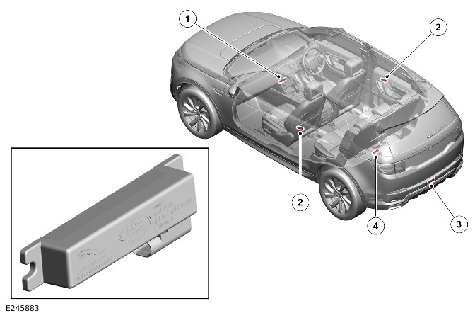
| ITEM | DESCRIPTION |
|---|---|
| 1 | LF antenna floor console |
| 2 | LF antenna in the rear door (quantity 2) |
| 3 | LF antenna in the rear bumper |
| 4 | LF antenna in the loadspace |
There are 2 LF antennas for the passive start system positioned in the following locations:
- There is 1 LF antenna located in the floor console behind the Integrated Control Panel (FCIM).
- There is 1 LF antenna located at the front of the loadspace floor below the second row seat backrest.
There are an additional 3 LF antennas for the passive entry system:
- There are 2 LF antennas in the rear doors.
- There is 1 LF antenna in the rear bumper.
The RFA transmits an LF signal through the LF antennas which is received by the smart key. The smart key then responds by transmitting a Radio Frequency (RF) signal which is received by the remote function receiver. The remote function receiver sends the received RF signal to the RFA for authorization.
RFA
Make sure ALL keys are available and placed on the center console within the vehicle. This must be done prior the configuration of a new RFA to the vehicle.
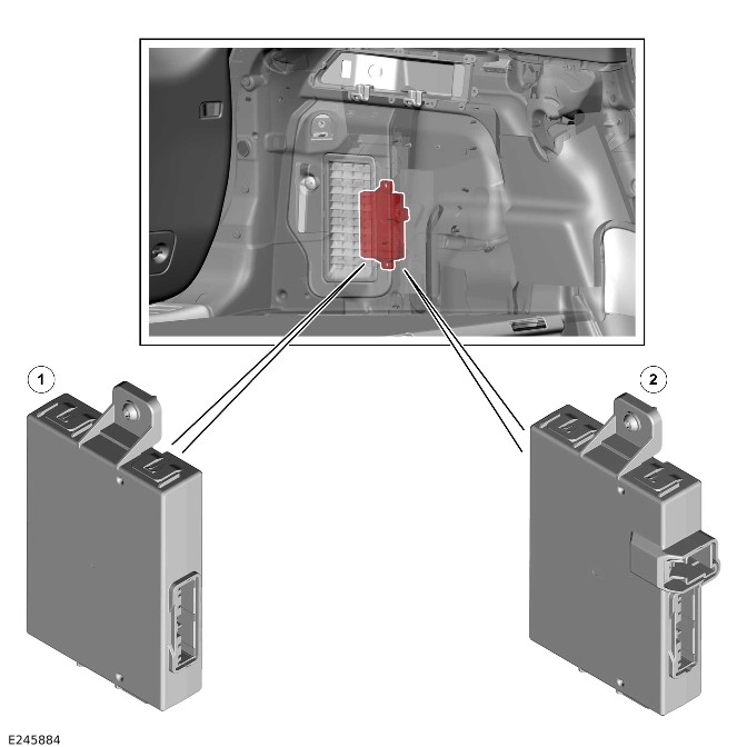
| ITEM | DESCRIPTION |
|---|---|
| 1 | RFA - Vehicles with passive start system (type A#) |
| 2 | RFA - Vehicles with Passive Entry Passive Start (PEPS) system (type B#) |
The RFA is located in the loadspace, above the rear left wheel arch. The RFA controls signal transmissions to and from the smart key and provides authorization to allow the vehicle to be entered and started. A permanent power feed is supplied to the RFA by the Passenger Junction Box (PJB). The RFA has a High Speed (HS) Controller Area Network (CAN) body systems bus connection to the BCM/GWM. The connection allows for authorizing vehicle unlocking and starting.
| PART NUMBER SUFFIX | VEHICLE SPECIFICATION |
|---|---|
| A# | Passive start system only |
| B# | PEPS system |
REMOTE FUNCTION RECEIVER
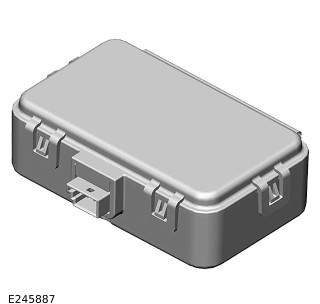
The remote function receiver is located in the rear headliner.
The remote function receiver receives RF signals from the smart key. When the remote function receiver receives a signal from the smart key, it passes the signal to the RFA.
There are 2 types of remote function receiver available as detailed in the table below.
| PART NUMBER SUFFIX | OPERATING FREQUENCY | VEHICLE SPECIFICATION |
|---|---|---|
| A# | 315 MHz | North American Specification (NAS), Japan and Korea |
| B# | 433 MHz | Europe and Rest of World (ROW) |
IAU
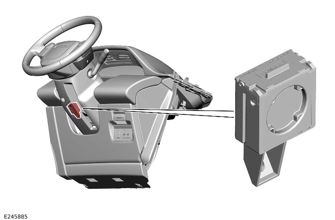
The IAU is installed on the inside of the steering column lower shroud and secured with a screw.
The IAU is used if the RFA is unable to authorize the smart key. If the RFA is unable to identify the smart key, the transponder within the smart key cannot be read in the conventional manner. The driver will be alerted to this by a chime and the following message in the Instrument Panel Cluster (IPC) message center:
- 'Smart Key Not Recognized - Reposition Or Place As Shown And Press Start Button'.
The transponder within the smart key can then be read by the IAU. Refer to 'Keyless Start Backup' section of this document.
PASSIVE ENTRY TRANSCEIVER
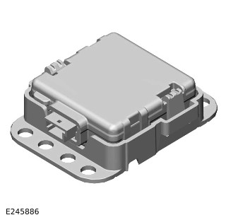
There are 2 passive entry transceivers in the vehicle, 1 on the front headliner and other on the rear of the headliner. The passive entry transceivers are used to locate the position of the smart key from the vehicle. The passive entry transceivers communicate with the RFA through a Local Interconnect Network (LIN) connection. Each passive entry transceiver has a power supply from the PJB and a ground connection. The passive entry transceivers calculate the distance of the smart key when:
- The passive entry sequence is initiated.
- A smart key is detected within the range.
Then the RFA allows the authorization of the smart key only if this distance is within permissible limits.
For additional information, refer to: Handles, Locks, Latches and Entry Systems (501-14 Handles, Locks, Latches and Entry Systems, Description and Operation).
ACTIVITY KEY - IF EQUIPPED
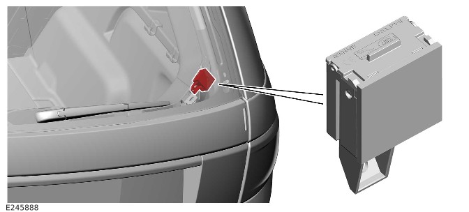
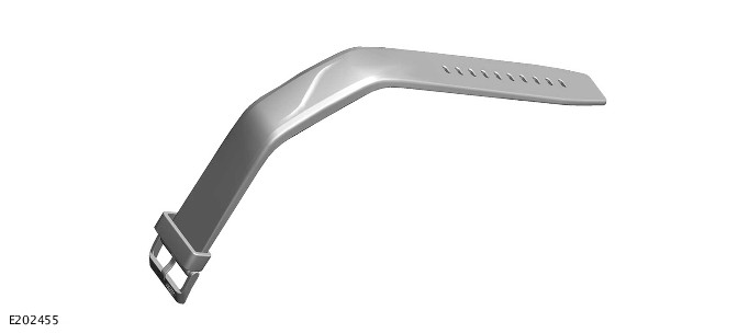
The activity key is a security wrist strap devised to support activities when the smart key would be difficult to keep secure, for example, swimming. The activity key is waterproof to a depth of 30 m (98 ft) and is shockproof.
The activity key contains a transponder that is uniquely coded to the vehicle. The activity key does not contain a battery. The activity key uses the energy that is created by the LF field when the activity key transceiver module is activated.
For additional information, refer to: Handles, Locks, Latches and Entry Systems (501-14 Handles, Locks, Latches and Entry Systems, Description and Operation).
SMART KEY
PEPS SYSTEM
The PEPS system includes enhancements to further improve vehicle security.
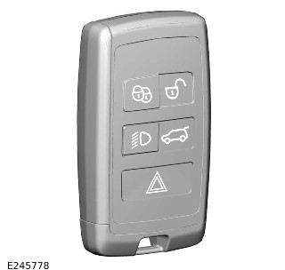
The smart key includes ultra wide band technology, designed to combat the latest security threats. Ultra wide band technology includes 2 new passive entry transceivers, which are programed to the vehicle in conjunction with smart keys.
PASSIVE START
The BCM/GWM sends a request message to the RFA. The RFA prompts all the LF antennas to output a signal. When the smart key is in the passenger compartment it detects the LF signals. The smart key responds with a data identification signal back to the remote function receiver. The remote function receiver sends the data identification signals to the RFA.
If the data received matches that stored in the RFA it continues the passive start process by communicating a 'smart key valid' signal. This signal is received by the BCM/GWM through the HS CAN body systems bus.
When the BCM/GWM receives the authorization and confirms the response with an internal calculation, it passes coded data to the IPC. This data is transmitted to the IPC on the HS CAN comfort systems bus. Upon confirmation from the IPC the ignition is enabled.
The BCM/GWM exchanges encrypted data with the Electric Steering Column Lock Control Module (VIM). The data will authorize the unlocking of the steering column. The IPC only provides a ground for the VIM motor. The BCM/GWM then sends a mobilization signal to the PCM.
The VIM is market dependent.
The BCM/GWM enables the fuel pump relay which provides a power supply to the Fuel Pump Driver Module (FPDM).
If the RFA fails to locate the smart key, the following message will appear in the IPC message center:
- 'Smart Key Not Recognized - Reposition Or Place As Shown And Press Start Button'
The keyless start backup process must be used to mobilize and start the vehicle.
ULTRA WIDE BAND OPERATION
With the introduction of ultra wide band technology, recognising the position of the smart key requires 2 pieces of distance information. The 2 passive entry transceivers are located in the headliner. There is 1 at the front and 1 at the rear, enabling full coverage inside and outside of the vehicle.
The following process takes place to validate the smart key:
- The RFA receives a door lock/unlock request.
- On receipt of the door lock/unlock request, challenge data is sent out from the RFA, through the LF antennas. This is at 125 kHz to the smart key.
- The smart key responds to the LF signal, processing the received message and replying to the vehicle using a separate RF channel.
- This response is received by the remote function receiver.
In addition the RFA sends a separate challenge through the passive entry transceivers to the smart key. The RFA sends this separate challenge in order to authenticate and obtain the smart key position with accuracy, using the following process:
- The challenge data is sent from the RFA by a LIN connection to the passive entry transceivers.
- The passive entry transceivers process and transmit the data through a separate RF signal, to the smart key.
- The frequency is 3.99 GHz (4.5 GHz in China).
- On receipt of the signal the smart key responds with an authentication message back to the passive entry transceivers. The response is sent through a RF signal.
When the smart key is validated the system operates in the normal way.
LF ZONES
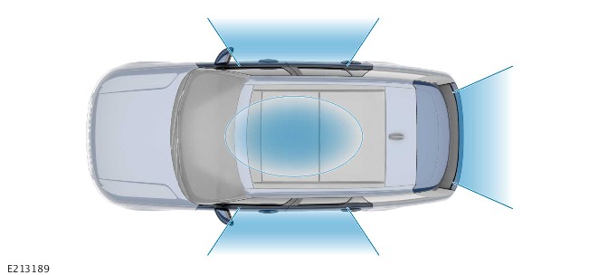
The message contained in the beacon signals varies based on each transmitter zone. For example, the message could vary based on if the zone was inside or outside the vehicle. This capability allows the smart key to send specific answers, triggering actions such as opening the passenger door or starting the engine.
A common security threat consists of relaying the messages exchanged between the vehicle and the smart key over long distances. This message range is indefinite, depending on the technology used. The attack is instigated by intercepting the beacon signal from the LF antenna in the vehicle to the smart key.
The security threat equipment used to intercept the messages is used to gain illegal entry to the vehicle and activate the passive start system.
SECURITY ENHANCEMENTS
To avoid security threats is to measure the real physical distance between the vehicle and the smart key. If the vehicle detects that the smart key is not physically close it will simply ignore the command received.
The technique consists of measuring the 'Time Of Flight' of the RF signal to estimate the distance between the transmitter and the receiver.
The use of 'Time Of Flight' and ultra wide band technology is designed to efficiently combat security threats. This provides accurate data transfer and message timing. Data transfer operates over a frequency range of 3.99 GHz (4.5 GHz in China) and a bandwidth of 500 MHz.
The ultra wide band signal consists of narrow pulses, making it tolerant of multi-path and in-band interference. The deployment of this technology makes illegal entry and starting attempts much more difficult to achieve.
Ultra wide band technology used in Jaguar Land Rover (JLR) vehicles is very low power and therefore short range. The vehicle system is configured to only take action when the measured distance is no more than 3 m (9.8 ft).
Ultra wide band is capable of achieving a 10 cm (0.32 ft) accuracy. This allows very accurate zones, triggering the lock release mechanism only when the vehicle user is within close proximity to the vehicle.
SECURITY THREATS
Current PEPS system vehicles are equipped with several LF 125 kHz antenna transmitters. The LF antennas cover specific zones inside and outside of the vehicle. The LF antennas send beacon signals. If the smart key is within range (1 m (3.2 ft)) of an antenna the ‘sleeping’ smart key picks up the LF signal. This signal wakes the smart key and triggers the processing of the received message. The smart key replies to the vehicle using a separate RF channel.
The smart key RF channel is 433 MHz in Europe (EU), 315 MHz in NAS and ROW markets.
KEYLESS START BACKUP
It is necessary to use the keyless start backup to disarm the alarm and start the engine in the following cases:
- The vehicle has been unlocked using the emergency key.
- The smart key is not detected by the vehicle.
The following process must be followed in this event:
- Operate the ignition switch if the RFA fails to locate the smart key. The message 'Smart Key Not Recognized - Position Of Place As Shown And Press Start Button' will be displayed in the IPC message center.
- Position the smart key against the bottom of the lower steering column with the smart key switches facing downward. The location of the IAU is denoted by ridges on the shroud.
- Operate the ignition switch with the brake or clutch pedal pressed to start the engine.
This process bypasses the data exchange between the RFA and the BCM/GWM. This is an inductive process and will operate even if the battery in the smart key is discharged. The transponder within the smart key is detected by the IAU. The IAU communicates this code with the BCM/GWM through a LIN connection. The BCM/GWM then initiates the vehicle start process in the normal manner.
SMART KEY BATTERY REPLACEMENT
It is recommended that all smart key batteries are replaced at the same time on PEPS vehicles.
To provide long term reliability of the smart key the battery must be replaced with a brand new, unused smart key battery. If a used smart key battery is installed the 'Smart Key Battery Low' message may not be cleared. To avoid contamination of the contacts the smart key battery should be removed from its packaging and installed into the smart key while wearing gloves.
To confirm that the replacement smart key battery is working correctly:
- Press the unlock switch twice while holding the smart key outside the vehicle.
- Enter the vehicle with the smart key.
- Operate the ignition switch.
- Confirm that 'Smart Key Battery Low' message is not displayed.
CONTROL DIAGRAM - 1 OF 3 - SMART KEY DETECTION

A = HARDWIRED: F = RF: O = LIN: W = LF TRANSMISSION: AZ = HS CAN BODY SYSTEMS BUS.
| ITEM | DESCRIPTION |
|---|---|
| 1 | RFA |
| 2 | BCM/GWM |
| 3 | LF antenna - Floor console |
| 4 | LF antenna - Loadspace |
| 5 | Smart key |
| 6 | Ground |
| 7 | Power supply |
| 8 | Remote function receiver |
| 9 | IAU |
CONTROL DIAGRAM - 2 OF 3 - PASSIVE START

A = HARDWIRED: F = RF: O = LIN: AV = HS CAN COMFORT SYSTEMS BUS: AX = FLEXRAY: BUS AZ = HS CAN BODY SYSTEMS BUS.
| ITEM | DESCRIPTION |
|---|---|
| 1 | BCM/GWM |
| 2 | RFA |
| 3 | VIM (if equipped) |
| 4 | IPC |
| 5 | PCM |
| 6 | Anti-Lock Brake System Control Module (ABS) |
| 7 | Fuel pump relay |
| 8 | PCM |
| 9 | Ground |
| 10 | Power supply |
| 11 | TCS - Vehicles with automatic transmission |
| 12 | Ignition switch |
| 13 | Brake pedal switch |
| 14 | Clutch Bottom of Travel (BOT) switch - Vehicles with manual transmission |
| 15 | Smart key |
| 16 | IAU |
CONTROL DIAGRAM 3 OF 3 - SMART KEY RECOGNITION
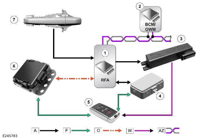
A = HARDWIRED: F = RF TRANSMISSION: O = LIN: W = LF TRANSMISSION: AZ = HS CAN BODY SYSTEMS BUS.
| ITEM | DESCRIPTION |
|---|---|
| 1 | RFA |
| 2 | BCM/GWM |
| 3 | LF antenna (quantity 5) |
| 4 | Remote function receiver |
| 5 | Smart key |
| 6 | Passive entry transceiver (quantity 2) |
| 7 | Exterior door handle |