Workshop manual New Range Rover Evoque (LZ) 2022
Battery and Charging System - General Information
12V System Disconnect (G2756419)
GENERAL PROCEDURES
Special Tool(s)
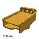
JLR-415-132
Universal Cable Lock-off
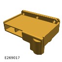
JLR-415-133
12 Volt Battery Lock-off
General Equipment
| Equipment name |
|---|
| Padlock |
Disconnection
NOTES:
- This procedure contains some variation in the illustrations depending on the vehicle specification, but the essential information is always correct.
- This procedure contains illustrations showing certain components removed to provide extra clarity.
- This procedure contains illustrations showing the auxiliary battery for right hand drive vehicles, left hand drive auxiliary battery is similar but on the right side of the engine compartment.
The following step(s) applies to:
All vehicles
- Read the battery charging health and safety precautions.Refer to: Health and Safety Precautions (100-00 General Information, Description and Operation).
- Obtain and record the preset radio frequencies.
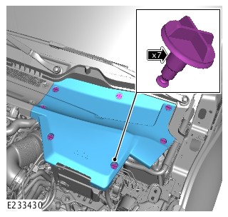
- Remove the 7 fasteners.
- Remove the cowl panel.
The following step(s) applies to:
Plug in hybrid electric vehicles only
- WARNING:
Jaguar Land Rover (JLR) Electric Vehicle Competent Person (EVCP) trained technicians only.
This procedure involves work on components associated with the High Voltage (HV) system. Only technicians qualified to EVCP level or higher are allowed to complete this procedure.
- It is mandated that all technicians involved with the steps in this procedure have read and understood the electric vehicle safety rules.Refer to: Electric Vehicle Safety Rules (414-01B, Description and Operation).
- Remove the engine compartment cross brace.Refer to: Engine Compartment Cross Brace (501-02 Front End Body Panels, Removal and Installation).
- Remove the nut.
- Release the battery negative cable from the Battery Monitoring Sensor (BMS).
The following step(s) applies to:
All vehicles
- Disconnect the electrical connector from the BMS sensor.
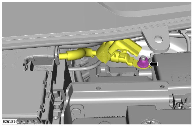
- Loosen the nut.
- Disconnect the startup battery negative terminal.
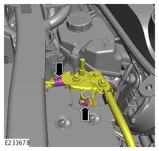
The following step(s) applies to:
Plug in hybrid electric vehicles only
- WARNING:
The key must be placed in the designated key box and secured by the responsible EVCP.
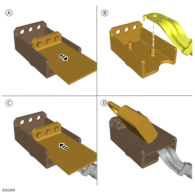
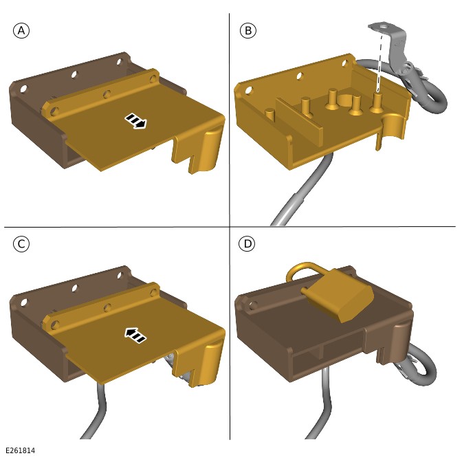
- Remove the lock-off tool lid.Special Tool(s): JLR-415-132
- Secure the battery negative cable in the lock-off tool.
- Install the lock-off tool lid.
- Install the padlock.General Equipment: Padlock
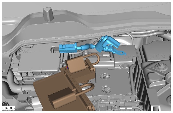
Position the lock-off tool over the battery negative terminal.
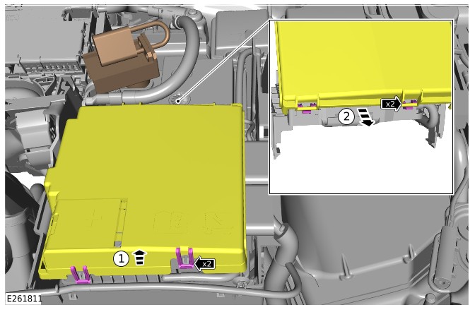
- Release the 2 clips.
- Remove the Battery Junction Box (BJB) lid.
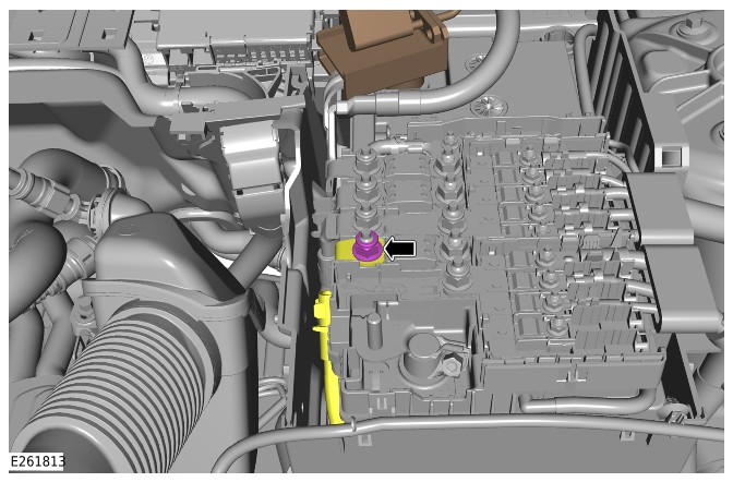
- Remove the nut.
- Release the Direct Current to Direct Current converter (DC/DC) cable from the BJB.
- WARNING:
The key must be placed in the designated key box and secured by the responsible EVCP.
- Remove the lock-off tool lid.Special Tool(s): JLR-415-133
- Secure the DC/DC cable in the lock-off tool.
- Install the lock-off tool lid.
- Install the padlock.General Equipment: Padlock
Disconnect the electrical connector from the auxiliary battery.
- Remove the nut.
- Release the cable from the power supply distribution box.
- WARNING:
The cable must be placed in the designated key box and secured by the responsible EVCP.
- Remove the auxiliary battery cable.
- Place the auxiliary battery cable in the designated key box and lock securely.
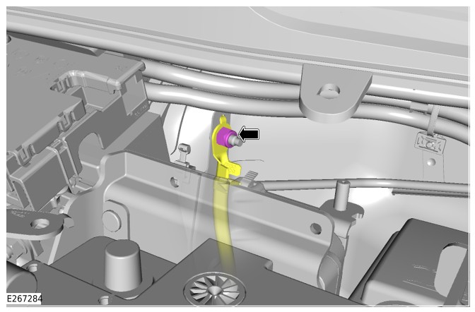
- Remove the nut.
- Release the auxiliary battery negative cable.
- WARNING:
The cable must be placed in the designated key box and secured by the responsible EVCP.
- Remove the lock-off tool lid.Special Tool(s): JLR-415-132
- Secure the auxiliary battery negative cable in the lock-off tool.
- Install the lock-off tool lid.
- Install the padlock.General Equipment: Padlock
Connect
The following step(s) applies to:
Plug in hybrid electric vehicles only
- Remove the auxiliary battery negative cable from the lock-off tool.
- Install the auxiliary battery negative cable.
- Install and tighten the nut.Torque: 18Nm
- Install the auxiliary battery cable.
- Install the cable to the power supply distribution box.
- Install and tighten the nut.Torque: 18Nm
- Connect the electrical connector to the auxiliary battery.
- Remove the DC/DC cable from the lock-off tool.
- Install the DC/DC cable.
- Install and tighten the nut.Torque: 18Nm
- Install the BJB lid.
The following step(s) applies to:
All vehicles
- CAUTION:
Make sure the BMS electrical connector is connected to the BMS control module, before installing the BMS onto the battery terminal.
- Connect the electrical connector to the BMS sensor.
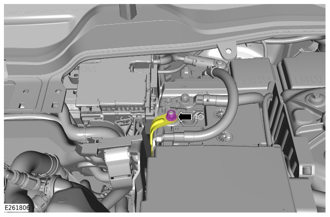
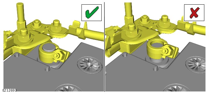
- Connect the startup battery negative terminal as illustrated.
- Tighten the nut.Torque: 6Nm
The following step(s) applies to:
Plug in hybrid electric vehicles only
The following step(s) applies to:
All vehicles
- Install the cowl panel.
- Install the 7 fasteners.
- Complete the door window motor initialization procedure.
- Enter the preset radio frequencies.
- Reset the clock to the correct time.
- Start the engine and allow to idle until the engine reaches normal operating temperature.
- Switch the engine off.