2021 DISCOVERY ANTI-THEFT - ACTIVE
ANTI-THEFT - ACTIVE (G2462522)
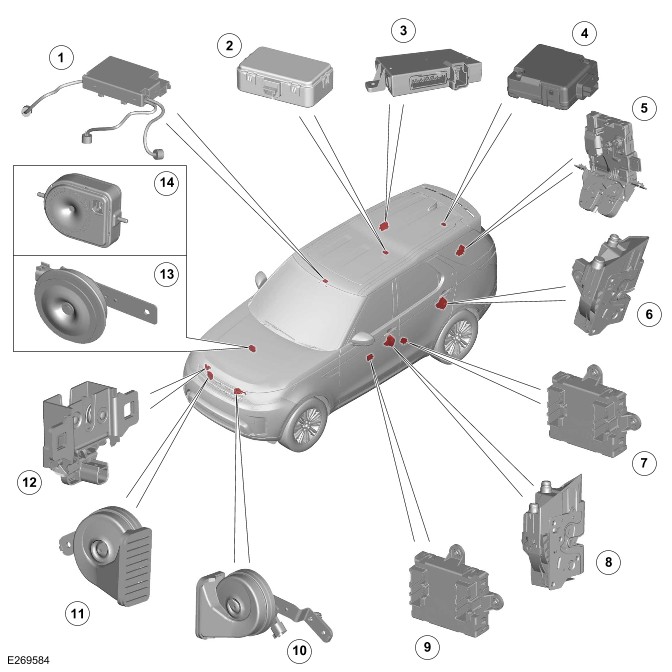
COMPONENT LOCATION - 1 OF 2
Right Hand Drive (RHD) variant shown, Left Hand Drive (LHD) variant is similar.
| ITEM | DESCRIPTION |
|---|---|
| 1 | Volumetric sensor |
| 2 | Radio Frequency (RF) receiver |
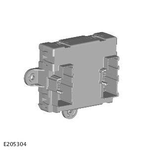
| 3 | Remote Function Actuator (RFA) |
| 4 | Passive entry transceiver - Rear |
| 5 | Tailgate ajar switch |
| 6 | Rear left door ajar switch |
| 7 | Passenger Rear Door Module (PRDM) |
| 8 | Passenger door ajar switch |
| 9 | Passenger Front Door Module (PDM) |
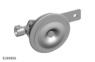
| 10 | Horn - Right |
| 11 | Horn - Left |
| 12 | Hood switch |
| 13 | Passive sounder (if equipped) |
| 14 | Battery Back-Up Sounder (BBUS) (if equipped) |
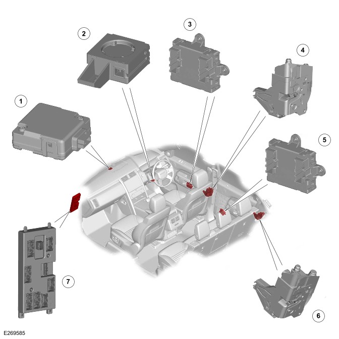
COMPONENT LOCATION - 2 OF 2
Right Hand Drive (RHD) variant shown, Left Hand Drive (LHD) variant is similar.
| ITEM | DESCRIPTION |
|---|---|
| 1 | Passive entry transceiver - Front |
| 2 | Immobilizer Antenna Unit (IAU) |
| 3 | Driver Front Door Module (DDM) |
| 4 | Driver door ajar switch |
| 5 | Driver Rear Door Module (DRDM) |
| 6 | Rear right door ajar switch |
| 7 | Body Control Module (BCM)/Gateway Module A (GWM) |
The active anti-theft system monitors all doors, hood and tailgate for unauthorized opening. In some markets the anti-theft system also incorporates monitoring of the vehicle interior and vehicle tilt sensing.
The following body system control modules control the active anti-theft system:
- The BCM/GWM
- The DDM
- The PDM
- The DRDM
- The PRDM
- The Instrument Panel Cluster Control Module (IPC)
- The RFA.
The BCM/GWM is the main controller in the system.
The BCM/GWM controls the following security functions, in addition to other vehicle functions:
- Single locking, double locking (market dependent) and unlocking (both central unlock and single point entry).
- Monitoring of hood switch, door ajar switches and the tailgate ajar switch of the central door locking system.
- The Passive Entry Passive Start (PEPS) system.
- The volumetric sensor.
- Smart key transponder reading.
- Security sounder - Passive sounder or BBUS.
- Passive arming and disarming.
- Panic alarm function.
- Interior lighting.
Depending on vehicle configuration, 2 levels of vehicle anti-theft alarm are available:
- Perimeter sensing mode - Monitors all opening panels.
- Perimeter with alarm sensing mode - Monitors the vehicle interior for intrusion and it also incorporates a tilt sensor to monitor if the vehicle is being moved.
Volumetric mode and tilt sensing are not available in certain markets.
All apertures (doors, tailgate and hood) are monitored for ajar status (doors ajar and latch status change).
A visual (through the turn signal indicators) and audible alarm is emitted through the security sounder and vehicle horns (market dependent) in the event of unauthorized access. The alarm is also triggered in the event of an unauthorized start request.
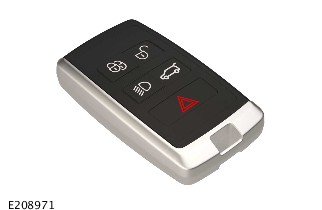
Smart Key
The smart key provides the following functionality:
- Unlock (central unlock or single point entry)
- Single lock and double lock (market dependent)
- Tailgate release
- Approach lighting
- Panic alarm.
The lock and unlock switches also control a 'lazy' lock and unlock feature. The 'lazy' lock and unlock feature automatically closes or opens the windows with an extended press of the applicable switch. This feature is only available in certain markets and is controlled in conjunction with the door modules.
Never double lock the vehicle with any person or animal inside.
Double locking is only available in certain markets.
The smart key contains an emergency key. The emergency key can be used in the event of failure of the smart key or the startup battery to unlock the vehicle. The driver door handle contains a concealed mechanical key barrel which can be used with the emergency key to access the vehicle. The emergency key to access the vehicle does not disable the perimeter sensing system. The visual and audible alarm is activated when the door is unlocked/opened. To cancel the alarm, the smart key must be held next to the and the ignition switch must be operated.
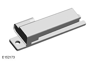
On the inside face of each door there is an emergency locking aperture. The aperture is used with the emergency key in the event of a failure of the startup battery to lock the vehicle.
Remove the cover and insert the emergency key into the aperture to mechanically lock each door in turn. The driver door is always the last door to be locked. Please make sure that the emergency key is removed from the emergency key aperture before each door is closed.
For additional information, refer to: Handles, Locks, Latches and Entry Systems (501-14 Handles, Locks, Latches and Entry Systems, Description and Operation).
DOOR MODULES
The DDM is shown, the other door modules are similar.
The door modules provide the interface between the door latches and the BCM/GWM. The door modules provide door latches status information and enable the door motors on request from the BCM/GWM.
Each door modules are controlled by the BCM/GWM through the High Speed (HS) Controller Area Network (CAN) body systems bus. Additionally, the DDM and the PDM also control the door mirror functions.
BODY CONTROL MODULE/GATEWAY MODULE
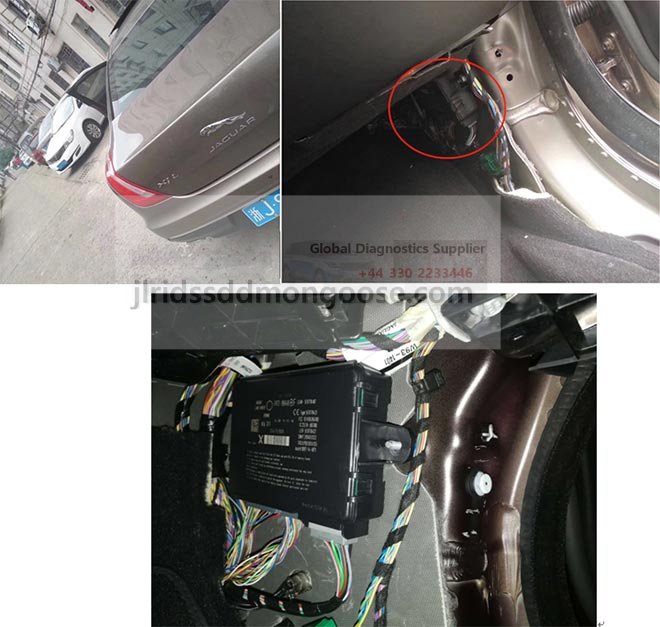
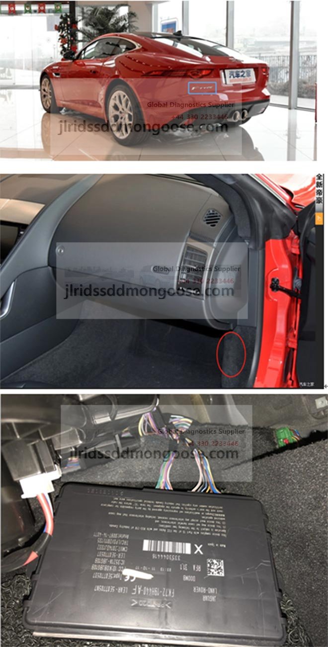
If the BCM/GWM is replaced, the new module requires configuring to the master car configuration using the Jaguar Land Rover (JLR) approved diagnostic equipment.
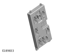
The BCM/GWM locates in the instrument panel, behind the glovebox.
The BCM/GWM controls the following functions:
- The horns
- The tailgate latch
- The tailgate ajar switch
- The turn signal indicators
- The fuel flap operation.
The BCM/GWM also has a connection to the Restraints Control Module (RCM) for automatic operation of the interior lights and the turn signal indicators in the event of an accident.
The BCM/GWM automatically arms and disarms the active anti-theft system when the vehicle is locked and unlocked. This is after successful confirmation that a valid smart key has been used.
INSTRUMENT PANEL CLUSTER
The BCM/GWM controls the security system status indicator which is incorporated in the main display in the IPC.
The IPC also controls the engine immobilization, in conjunction with the following control modules:
- The BCM/GWM
- The Powertrain Control Module (PCM)
- The Anti-Lock Brake System Control Module (ABS).
The PCM controls the engine crank and fuel functions and the ABS controls the tilt function. The PCM and ABS communicate to each other after the BCM/GWM processes the valid smart key information.
The security system status indicator is a red Light Emitting Diode (LED) located in the IPC. When the vehicle is in Power Mode 0 (Vehicle locked and armed), the indicator gives a visual indication of the active anti-theft system to show if the security system is set.
When the vehicle is in Power Mode 6 (ignition ON), the indicator provides a visual indication of the status of the passive anti-theft (engine immobilization) system. If the immobilization system is operating correctly, the LED will be illuminated for 3 seconds after Power Mode 6 (ignition ON) and then extinguishes.
When a fault exists in the immobilization system, the LED is either permanently illuminated or flashing for 60 seconds. The LED indicates that a fault exists and a Diagnostic Trouble Code(s) (DTC) has been recorded. After the 60 second period, the LED flashes at different frequencies which indicate the nature of the fault.
Operation of the security system status indicator is controlled by the IPC. The IPC varies the flash rate of the LED to indicate the system status of the alarm and the immobilization systems.
Operation of the security system status indicator is also controlled by the BCM/GWM.
| ALARM/IMMOBILIZATION STATUS | ALARM INDICATOR STATUS | ALARM INDICATOR FUNCTION |
|---|---|---|
| UNSET | No flash | LED remains off |
| SET - Perimeter alarm mode | Flashing | LED flashes 1 time in every 2 seconds |
| SET - Perimeter with alarm sensing mode | Flashing | LED flashes 1 time in every 2 seconds |
| ACTIVE - Triggered | Flashing | LED flashes 1 time in every 2 seconds |
| UNSET - alarm activated during previous SET cycle | No flash | LED remains off |
SECURITY SYSTEM SOUNDER
Depending on vehicle configuration there is a passive sounder or a BBUS is located behind the secondary bulkhead panel on the driver side.
The passive sounder is connected directly to the BCM/GWM. The BCM/GWM activates the passive sounder as the first security sounder when the alarm is triggered.
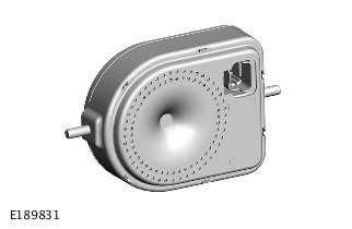
The BBUS incorporates an integrated tilt sensor which monitors the vehicle altitude. The tilt sensor can detect if the vehicle is being moved, towed or raised. The tilt sensor communicates to the BCM/GWM to indicate a trigger to activate the alarm.
Operation of the BBUS and tilt sensor is controlled by the BCM/GWM on the Local Interconnect Network (LIN) connection. An integral, rechargeable battery power feed is supplied to the BBUS if the vehicle startup battery supply from the BCM/GWM is interrupted.
VEHICLE HORNS
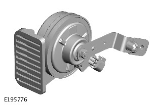
The vehicle horns are located above the front bumper armature. The horns have a switched power supply through the horn relay located in the Engine Junction Box (EJB). The horns are switched through the steering wheel, connected through the clockspring to the BCM/GWM. The BCM/GWM activates the horns as a secondary security sounder when the alarm is triggered.
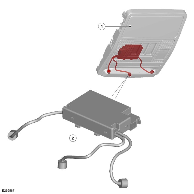
VOLUMETRIC SENSOR - IF EQUIPPED
| ITEM | DESCRIPTION |
|---|---|
| 1 | Overhead console |
| 2 | Volumetric sensor |
The volumetric sensor is located in a central position in the overhead console. The volumetric sensor comprises 3 sensors which allow the passenger compartment to be monitored. The BCM/GWM provides a permanent power supply for the volumetric sensor. The sensor signals are transmitted to the BCM/GWM on a LIN connection.
The volumetric sensors are activated when the vehicle is double locked. The vehicle can be locked and alarmed with the volumetric sensors deactivated. This can be achieved by single locking the anti-theft active system or by deactivating the alarm sensors in the 'Vehicle settings' menu on the Interactive Display Module 'A' (IDMA).
In certain markets (Benelux) the volumetric sensors (if equipped) are activated on single locking as a market requirement.
When volumetric sensors are active and the vehicle battery voltage falls below 9V, the BCM/GWM ignores any inputs to prevent false alarm activation.
The BCM/GWM ignores the signals from the volumetric sensor for the first 15 - 30 seconds. This allows time for the passenger compartment to settle and prevent false alarm activation.
If the tailgate is opened through the smart key, the volumetric sensor and the tilt sensor are inhibited until the tailgate is closed.
HOOD SWITCH
The hood switch is attached to the underside of the left hood latch and operated by movement of the latch mechanism. When the latch opens, the switch closes and connects a ground to the BCM/GWM.
SMART KEY
The smart key does not need to be held adjacent to the IAU, however this function is still supported to cover error states.
The PEPS system includes enhancements to further improve vehicle security.
The smart key includes ultra wide band technology, designed to combat the latest security threats. Ultra wide band technology includes 2 passive entry transceivers, which are programed to the vehicle in conjunction with smart keys.
For additional information, refer to:
PASSIVE ENTRY TRANSCEIVER
There are 2 passive entry transceivers in the vehicle. There is 1 passive entry transceiver located in the top of the instrument panel, adjacent to the center speaker. The second passive entry transceiver is located on the rear of the headliner, above the loadspace area.
The passive entry transceivers are used to locate the position of the smart key from the vehicle. The passive entry transceivers communicate with the RFA through a LIN connection. Each passive entry transceiver has a power supply from the Passenger Junction Box (PJB) and a ground connection.
When the passive entry sequence is initiated and a smart key is detected within the range, the passive entry transceivers calculate the distance of the smart key. Then the RFA allows the authorization of the smart key only if this distance is within permissible limits.
For additional information, refer to: Handles, Locks, Latches and Entry Systems (501-14 Handles, Locks, Latches and Entry Systems, Description and Operation).
DISARMING
The BCM/GWM automatically arms and disarms the anti-theft system when it operates the central door locking system. The BCM/GWM also locks and unlocks the Electric Steering Column Lock (ESCL) (if equipped) when it operates the central door locking system.
On vehicles without a volumetric sensor, only the perimeter mode is available to monitor the hinged panels and the validity of the smart key.
When perimeter sensing is active, the BCM/GWM monitors aperture ajar switches. The ajar switches are located in the latch mechanisms of the doors, in the tailgate and hood latch.
When volumetric sensors are active, the BCM/GWM monitors the passenger compartment for movement using the volumetric sensor.
When the tilt sensors are active, the BCM/GWM monitors the vehicle for raising using a tilt sensor located within the BBUS.
ARMING
The anti-theft active system is armed in the perimeter mode when the vehicle is either locked or double locked. On vehicles with the passive entry system, the anti-theft active system is armed in the perimeter mode when the lock/unlock switch on 1 of the exterior door handles is used.
Smart key switch selection and the lock/unlock switch selection on the exterior door handles are relayed to the BCM/GWM. The signal is sent by the RFA on the HS CAN body systems bus.
Perimeter mode only monitors the hinged panels and validity of the smart key in the RFA.
The volumetric sensor monitors the passenger compartment for intrusion. If the vehicle is equipped with a BBUS the vehicle altitude is also monitored when perimeter with alarm sensing mode is active.
Perimeter with alarm sensing mode is activated by the following manner:
- A second press of the lock switch on the smart key.
- Using the lock switch on 1 of the exterior door handles, on vehicles with the passive entry system.
The second press of the switch must occur within 3 seconds of the first press. The second press of the lock switch also activates the perimeter sensing double locking feature.
In certain markets (Benelux) the volumetric sensors (if equipped) are activated on single lock as per latest market requirements.
The BCM/GWM arms the active anti-theft system when it single locks or double locks the vehicle, providing all the following conditions are met:
- All doors, tailgate and hood are closed.
- The BCM/GWM is not in transit mode.
When the vehicle has successfully completed its locking routine, a single short flash of the turn signal indicators indicates the single locked condition.
If double locking is activated, then the confirmation will be given by:
- A double flash of the turn signal indicators.
- 1 short flash for locked.
- 1 long flash on completion of double locked.
If ‘audible lock warning’ is enabled, an audible chirp shall also be emitted from the BBUS on double lock. This feature can be turned on and off in the 'Vehicle settings' menu on the IDMA.
Mislock
When a lock or double lock request is received from a smart key, the anti-theft security system remains disarmed when:
- Any doors, tailgate or hood is open/ajar.
- Vehicle is in Power Mode 6 (ignition ON).
The BCM/GWM generates a short mislock sound from the BBUS or the passive sounder. The turn signal indicators do not flash. Each attempt to lock is confirmed by an audible chime being emitted.
Disarming
The BCM/GWM disarms the active anti-theft system to prevent false alarm activation under certain conditions as follows:
- The system is in perimeter with alarm sensing mode and the startup battery voltage decreases to less than 9V. - The BCM/GWM disables the perimeter with alarm sensing mode and remain in perimeter mode only. This prevents false alarm activation because the volumetric sensor cannot operate correctly below 9V.
- The BCM/GWM deactivates the BBUS when the startup battery voltage decreases from 9.5V to 9V in more than a 30 minute period. At voltages below 9V, the BCM/GWM does not generate the 'heartbeat' signal to the BBUS. The BBUS interprets this as the BCM/GWM has been tampered with and activates its sounder. When the startup battery voltage subsequently rises to more than 9.5V, the BCM/GWM re-arms the BBUS.
- The vehicle automatically re-locks and re-arms the active anti-theft system when unlocking the vehicle and within 40 seconds a hinged panel is not opened. The function prevents leaving the vehicle unlocked and disarmed by accidental operation of the smart key unlock switch/exterior handle.
Alarm
When the alarm is triggered, the BCM/GWM activates audible and visual warnings. The audible warnings are produced by the passive sounder or the BBUS and the horns (market dependent). Visible indications are produced using the turn signal indicators.
The BCM/GWM activates the following components:
- The passive sounder or the BBUS.
- The horns.
- The visual indications.
The BCM/GWM activates the components for 30/60 seconds, depending on the market. The activation is stopped for 10 seconds. When the alarm trigger is still present, the BCM/GWM will cycle again for 30/60 seconds. The activation repeats for up to a maximum of 10 cycles (3 cycles in certain markets) per trigger source of 30/60 seconds for any 1 arming period.
The BCM/GWM will ignore the trigger cause if the 10 cycles (3 cycles in certain markets) have been completed and the alarm trigger is still present or until it receives a disarm signal.
When the BBUS is triggered due to tamper detection, the visual indication using the turn signal indicators is not activated.
The alarm can be triggered by:
- Any of the hinged panels being opened.
- Any of the doors being unlocked.
- The volumetric sensor detects a movement inside the vehicle.
- The tilt sensor detects vehicle movement.
- An ignition tamper is detected (invalid smart key).
BATTERY BACK-UP SOUNDER
When a BBUS is equipped, it is also armed with the perimeter mode lock request. However, the tilt functionality is not enabled in perimeter mode depending on market/single/double locking latches.
On receipt of the arming signals, the BBUS and the tilt sensor respond with a status message. If the BCM/GWM does not receive the status signals within a period of time, there is a fault in the system. The BCM/GWM responds with a disarm signal to either the sounder and/or the tilt sensor and stores a related DTC. The sounder is disarmed when the active anti-theft system is armed and the system is subsequently triggered. The BCM/GWM still energizes the horn relay and uses the horns to sound the audible warning in place of the BBUS.
When the BBUS is armed, the BCM/GWM sends a periodic (heartbeat) signal to the BBUS. The signal prompts the BBUS to monitor the startup battery supply and the LIN connection with the BCM/GWM.
The BBUS operates in the following cases:
- The BBUS receives an alarm signal from the BCM/GWM or the tilt sensor.
- The power supply or the LIN connection to the BCM/GWM is disrupted.
The tilt sensor measures the longitudinal and lateral angle of the vehicle over a range of ±16° from the horizontal. When the active anti-theft system is armed in perimeter with alarm sensing mode, the tilt sensor:
- Stores the current vehicle angles in its memory.
- Monitors the tilt sensor readings.
When the vehicle angle changes in either direction by more than the alarm limit threshold, the tilt sensor communicates to the BCM/GWM in order to activate the BBUS.
When the security system is active and the battery or the BBUS is disconnected, the BBUS continues to sound without the visual indication of the turn signal indicators flashing.
SINGLE POINT ENTRY
The single point entry feature only unlocks the driver door, all other doors remain single locked. A single press of the unlock switch on the smart key, only unlocks the driver door. A second press is required to unlock the remaining doors and the tailgate.
When the vehicle is double locked, the first press of the unlock switch on the smart key unlocks the driver door.
The remaining doors revert to the single locked state and can therefore be unlocked using the following:
- A further press of the smart key unlock switch.
- The central door locking lock/unlock switch on the driver door.
- The interior door handles on the passenger doors.
- Passive entry through any passenger door.
Access to the tailgate can be achieved through:
- A further press of the smart key unlock switch.
- The smart key tailgate open switch.
- The tailgate open switch on the instrument panel.
- The central door locking lock/unlock switch on the driver door.
- The interior door handles on the passenger doors.
- Passive entry through any passenger door.
- Passive entry through the tailgate open switch.
Changing from central door locking to single point entry can be done by:
- Pressing the lock and unlock switches on the smart key simultaneously. The turn signal indicators flash to confirm that the function change has been performed.
- Using the 'Vehicle settings' menu on the IDMA.
GLOBAL OPEN/CLOSE
The global open/close feature is not available in all markets.
A global open and close feature can be operated from the smart key. This feature allows the vehicle windows to be opened/closed through a single press of the lock or unlock switch. The switch must be pressed and held for more than 2 seconds to activate the global open/close feature. The windows must be initialized for the global functionality to work.
SMART KEY ADDITIONAL FEATURES
In addition to the lock and unlock switches, the smart key has convenience switches.
A headlamp convenience switch can be pressed to operate the headlamps to assist departure or approach to the vehicle. A single press of the switch operates the headlamps for approximately 25 seconds, after which time they turn off automatically. A second press of the switch turns off the headlamps when the 25 second period has not been reached. Operating the ignition switch within the 25 second period, also turns off the headlamp convenience feature.
A panic alarm feature allows the vehicle security system to be activated using the smart key. The panic alarm switch, identified by a triangle symbol, can be operate and held for more than 3 seconds to activate the vehicle alarm.
To cancel the panic alarm feature perform 1 of the following:
- Operate the panic alarm switch 3 times.
- Press and hold the panic switch for 3 seconds.
- Operate the ignition switch.
To prevent accidental cancellation, the panic alarm cannot be canceled within 5 seconds of being activated.
When the vehicle is unlocked using the unlock switch on the smart key, the vehicle electrical system initiates convenience mode.
The following systems become active in convenience mode:
- Memory - Seat adjustment and mirror position.
- Interior and exterior lighting.
- Audio system.
- The IPC message center.
- Horn.
- Cigar lighter/12V accessory socket.
ULTRA WIDE BAND OPERATION
With the introduction of ultra wide band technology, recognizing the position of the smart key requires 2 pieces of distance information. There are 2 passive entry transceivers installed in the vehicle. The 2 passive entry transceivers provide full coverage inside and outside of the vehicle.
The following process takes place to validate the smart key:
- The RFA receives a door lock/unlock request.
- On receipt of the door lock/unlock request, challenge data is sent out from the RFA, through the Low Frequency (LF) antennas at 125 kHz to the smart key.
- The smart key responds to the LF signal, processing the received message and replying to the vehicle using a separate RF channel:
- 433 MHz for Europe and Rest of World (ROW) market vehicles.
- 315 MHz for North American Specification (NAS) and Japan market vehicles.
- This response is received be the RF receiver, which transmits the data to the RFA.
In addition, the RFA sends a separate challenge through the passive entry transceivers to the smart key.
The RFA sends this separate challenge in order to authenticate and obtain the smart key position with accuracy, using the following process:
- The challenge data is sent from the RFA through LIN connection to the passive entry transceivers.
- The passive entry transceivers process and transmit the data, through a separate RF signal, at 3.99 GHz (4.5 GHz in China) to the smart key.
- On receipt of the signal the smart key responds with an authentication message back to the passive entry transceivers. The respond is sent through a RF signal on the LIN connection.
When the smart key is validated the system operates in the normal way.
LOW FREQUENCY ZONES
Some variation in the illustration may occur, but the essential information is always correct.
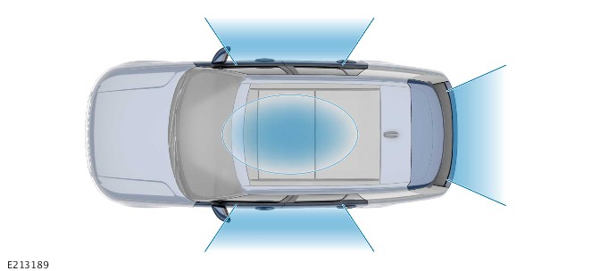
The message contained in the beacon signals varies based on each transmitter zone.
For example, the message could vary based on if the zone was:
- Inside or outside the vehicle.
- On the driver side or the passenger side.
- In the loadspace.
This capability allows the smart key to send specific answers, triggering actions such as opening the passenger door or starting the engine.
A common security threat consists of relaying the messages exchanged between the vehicle and the smart key over long distances. This message range is indefinite, depending on the technology used. The attack is instigated by intercepting the beacon signal from the LF antenna in the vehicle to the smart key.
The equipment used to intercept the messages, exchanged between the vehicle and the smart key. The equipment is used to gain illegal entry to the vehicle and activate the passive start system.
For additional information, refer to: Anti-Theft - Passive (419-01B Anti-Theft - Passive, Description and Operation).
DIAGNOSTICS
The BCM/GWM records any DTC and related data. Read the DTC and related data with the JLR approved diagnostic equipment. The JLR approved diagnostic equipment can read live data and activate certain components.
CONTROL DIAGRAM - 1 OF 2 - SMART KEY RECOGNITION AND DETECTION

A = HARDWIRED: F = RF TRANSMISSION: O = LIN: W = LF TRANSMISSION: AZ = HS CAN BODY SYSTEMS BUS: AH = SERIAL COMMUNICATION LINE.
| ITEM | DESCRIPTION |
|---|---|
| 1 | RFA |
| 2 | BCM/GWM |
| 3 | LF antenna - Floor console |
| 4 | Smart key |
| 5 | Activity key (if equipped) |
| 6 | LF antenna - Loadspace |
| 7 | Ground |
| 8 | Power supply |
| 9 | Door lock/unlock switch - Exterior door handle |
| 10 | Passive entry transceiver - Front |
| 11 | Passive entry transceiver - Rear |
| 12 | RF receiver |
| 13 | IAU |
CONTROL DIAGRAM - 2 OF 2
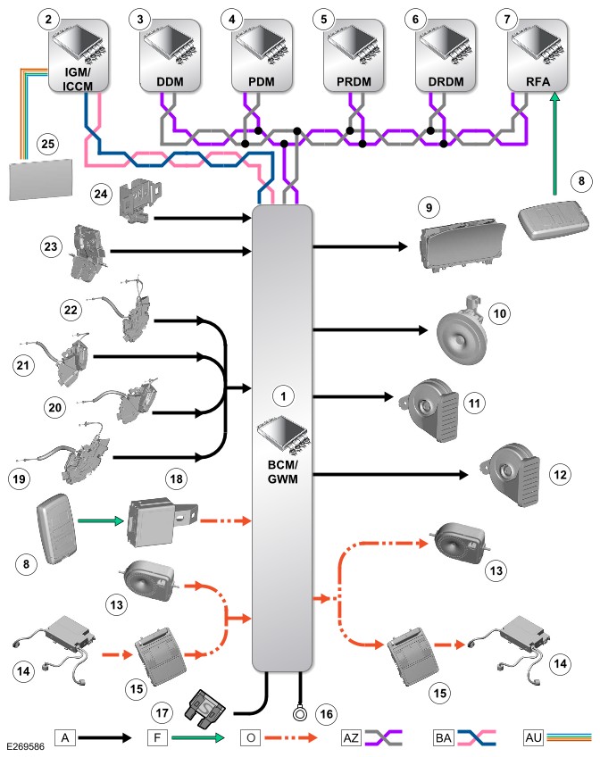
A = HARDWIRED: F = RF TRANSMISSION: O = LIN: AZ = HS CAN BODY SYSTEMS BUS: BA = HS CAN HUMAN MACHINE INTERFACE (HMI) SYSTEMS BUS.
| ITEM | DESCRIPTION |
|---|---|
| 1 | BCM/GWM |
| 2 | Front Infotainment Control Module (IGM / ICCM) |
| 3 | DDM |
| 4 | PDM |
| 5 | PRDM |
| 6 | DRDM |
| 7 | RFA |
| 8 | Smart key |
| 9 | IPC - Security system status indicator |
| 10 | Passive sounder (if equipped) |
| 11 | Horn - Right |
| 12 | Horn - Left |
| 13 | BBUS (if equipped) |
| 14 | Volumetric sensor |
| 15 | Overhead console |
| 16 | Ground |
| 17 | Power supply |
| 18 | IAU |
| 19 | Front right door ajar switch |
| 20 | Front left door ajar switch |
| 21 | Rear right door ajar switch |
| 22 | Rear left door ajar switch |
| 23 | Tailgate ajar switch |
| 24 | Hood switch |
| 25 | IDMA |
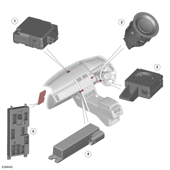
COMPONENT LOCATION - 1 OF 2
Right Hand Drive (RHD) variant shown, Left Hand Drive (LHD) variant is similar.
| ITEM | DESCRIPTION |
|---|---|
| 1 | Passive entry transceiver - Front |
| 2 | Ignition switch |
| 3 | Immobilizer Antenna Unit (IAU) |
| 4 | Low Frequency (LF) antenna - Floor console |
| 5 | Body Control Module (BCM)/Gateway Module A (GWM) |
COMPONENT LOCATION - 2 OF 2
Right Hand Drive (RHD) variant shown, Left Hand Drive (LHD) variant is similar.

| ITEM | DESCRIPTION |
|---|---|
| 1 | Passive entry transceiver - Rear |
| 2 | Radio Frequency (RF) receiver |
| 3 | LF antenna - Rear right door - Passive Entry Passive Start (PEPS) (if equipped) |
| 4 | Remote Function Actuator (RFA) |
| 5 | LF antenna - Rear - PEPS (if equipped) |
| 6 | LF antenna - Loadspace - Vehicles without third row seats |
| 7 | LF antenna - Passenger compartment - Vehicles with third row seats |
| 8 | LF antenna - Rear left door - PEPS (if equipped) |
The passive start system relies on the detection of a uniquely coded smart key through LF antennas strategically situated within the vehicle. The antennas make sure, that the smart key is always within the active transmission zone of the antennas, wherever the smart key is placed inside the vehicle. For this reason, the orientation and positioning of the antennas is critical for the correct functioning of the system. The smart key also operates the passive entry system.
For additional information, refer to: Handles, Locks, Latches and Entry Systems (501-14 Handles, Locks, Latches and Entry Systems, Description and Operation).
The system provides a secure interface between the BCM/GWM and the Powertrain Control Module (PCM) to prevent unauthorized starting of the engine. This is achieved by immobilization of the engine crank system and the fuel system, using encoded data exchange between the smart key and multiple control modules.
Engine starting is initiated when the encoded data exchange between the smart key and the control modules is verified. The engine management system will then allow engine crank and fueling when an authorization data message is received from the BCM/GWM.
The engine can be started by pressing the ignition switch when PARK (P) position is selected, and the brake pedal is pressed.
LOW FREQUENCY ANTENNAS
Depending on vehicle specification, the LF antennas are positioned in the following locations:
- In the floor console, behind the Integrated Control Panel (ICP).
- In the loadspace, under the floor trim panel - On vehicles without third row seats.
- In the passenger compartment, beneath the third row seats - On vehicles with third row seats.
- There is 1 LF antenna located in each rear door - On vehicles with PEPS system.
- There is 1 LF antenna located behind the rear bumper - On vehicles with PEPS system.
The RFA transmits a LF signal through the antennas which is received by the smart key. The smart key then responds by transmitting a RF signal which is received by the RF receiver and passed to the RFA for authorization.
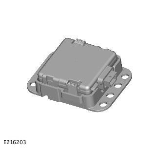
REMOTE FUNCTION ACTUATOR
Make sure ALL keys are available and placed on the center console within the vehicle. This must be done before a new RFA configuration.
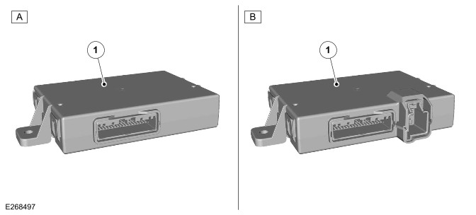
| ITEM | DESCRIPTION |
|---|---|
| A | Vehicles with passive start system |
| B | Vehicles with PEPS system |
| 1 | RFA |
The RFA located in the right side of the loadspace, behind the C-pillar upper trim panel. The RFA is attached to the vehicle body with 2 nuts.
The RFA controls signal transmissions to and from the smart key and provides authorization to allow the vehicle to be entered and started. The module has a High Speed (HS) Controller Area Network (CAN) body systems bus connection to the BCM/GWM for vehicle unlock and engine start authorization.
| PART NUMBER SUFFIX | VEHICLE SPECIFICATION |
|---|---|
| A# | Passive start system only |
| B# | PEPS system |
IMMOBILIZER ANTENNA UNIT
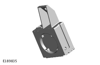
The IAU is installed on the inside of the steering column lower cover and secured with a screw.
The IAU is used if the RFA is unable to authorize the smart key. The RFA is unable to identify the smart key if the smart key battery voltage is low or there is RF interference. The transponder within the smart key can be read in the conventional manner.
The driver will be alerted to this by a chime and the following message in the Instrument Panel Cluster Control Module (IPC) message center:
- ‘Place Smart key as Shown, and Press Start Button’.
PASSIVE ENTRY TRANSCEIVER
There are 2 passive entry transceivers in the vehicle. There is 1 passive entry transceiver located in the top of the instrument panel, adjacent to the center speaker. The second passive entry transceiver is located on the rear of the headliner, above the loadspace area.
The passive entry transceivers are used to locate the position of the smart key from the vehicle. The passive entry transceivers communicate with the RFA through a Local Interconnect Network (LIN) connection. Each passive entry transceiver has a power supply from the Passenger Junction Box (PJB) and a ground connection.
When the passive entry sequence is initiated and a smart key is detected within the range, the passive entry transceivers calculate the distance of the smart key. Then the RFA allows the authorization of the smart key only if this distance is within permissible limits.
For additional information, refer to: Handles, Locks, Latches and Entry Systems (501-14 Handles, Locks, Latches and Entry Systems, Description and Operation).
SMART KEY
The smart key is identical for all vehicle specifications but differs in the preset frequency and power that the smart key operates.
The smart key for each vehicle specification is identified by a suffix change to the base part number as follows:
| PART NO. SUFFIX | OPERATING FREQUENCY | VEHICLE SPECIFICATION |
|---|---|---|
| A# | 315 MHz | North American Specification (NAS) and Japan |
| B# | 433 MHz | Europe and Rest of World (ROW) |
Each smart key features a unique identification code that is programed within the integral transponder. The RF signal produced by the smart key contains the unique identification code and a rolling code. During vehicle production, the unique identification codes of the valid smart keys are programed into the RFA. The rolling codes are also synchronized with the RFA.
For additional information, refer to: Handles, Locks, Latches and Entry Systems (501-14 Handles, Locks, Latches and Entry Systems, Description and Operation).
ACTIVITY KEY - IF EQUIPPED
When the vehicle is locked with the activity key, any valid smart key remaining inside the vehicle is disabled. Any valid smart key outside the vehicle remains enabled.
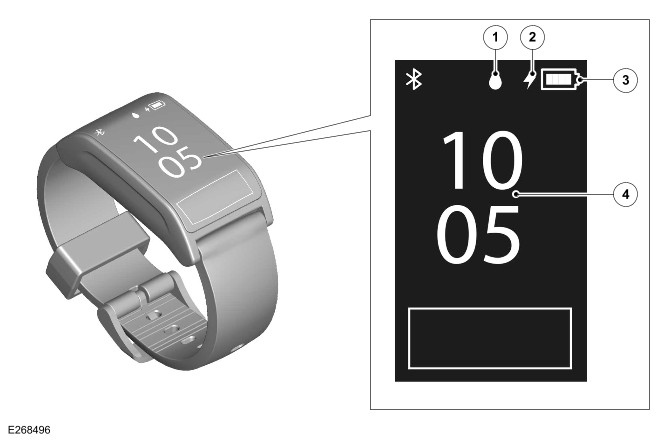
| ITEM | DESCRIPTION |
|---|---|
| 1 | Water lock symbol |
| 2 | Charge symbol |
| 3 | Charge status |
| 4 | Home screen |
The activity key is a touch display with wrist strap. The activity key is designed to support situations where the smart key might be obtrusive or difficult to keep secure. The activity key is waterproof to a depth of 40 m (131 ft) and is shockproof. Care should be taken during certain sporting activities.
The activity key provides full functionality of PEPS.
When the activity key is worn on the wrist, the smart key can remain inside the vehicle, but it is not mandatory. When the activity key is activated, the vehicle locks, the security system arms, and the PEPS functions are disabled for any smart key, remaining inside the vehicle.
The activity key uses the same technology for authentication and signal transmission with the RFA as the smart key. The LF signals from the LF antennas are initiate the authentication process. The activity key responds with a RF signal, which is transmitted to the RFA through the RF receiver. The passive entry transceivers are also activated to calculate the distance of the activity key from the vehicle.
The activity key for each vehicle specification is identified by a suffix change to the base part number as follows:
| PART NO. SUFFIX | OPERATING FREQUENCY | VEHICLE SPECIFICATION |
|---|---|---|
| A# | 315 MHz | North American Specification (NAS) and Japan |
| B# | 433 MHz | Europe and Rest of World (ROW) |
PASSIVE ENTRY PASSIVE START SYSTEM
The smart key does not need to be held adjacent to the IAU, however this function is still supported to cover error states.
The PEPS system include enhancements to further improve vehicle security.
The smart key includes ultra wide band technology, designed to combat the latest security threats. Ultra wide band technology includes the 2 passive entry transceivers, which are programed to the vehicle in conjunction with smart keys.
RADIO FREQUENCY RECEIVER
The RF receiver is installed on the top of the headliner, in line with the C-pillars. The RF receiver provides functionality for the remote control of the central door locking system.
The RF receiver transmission is received from the smart key to enable key identification. The RF receiver converts the signals transmitted by the smart key into digital messages, and then transmits the message through a serial communication line to the RFA.
For additional information, refer to: Handles, Locks, Latches and Entry Systems (501-14 Handles, Locks, Latches and Entry Systems, Description and Operation).
At the request of the BCM/GWM the RFA prompts each of the internal LF antennas to output a signal. When the smart key is in the vehicle, it detects the LF signals and responds with a RF data-identification signal back to the RFA through the RF receiver.
If the data received matches that stored in the RFA, it continues the passive start process.
A 'Smart key valid' signal is sent to the BCM/GWM through the HS CAN body systems bus.
The BCM/GWM receives the authorization and confirms the response with an internal calculation. The BCM/GWM passes coded data to the IPC on the HS CAN Human Machine Interface (HMI) systems bus. Upon confirmation from the IPC, Power Mode 6 (ignition ON) status enabled.
Before the BCM/GWM sends a mobilization signal to the PCM, it will exchange encrypted data with the Electric Steering Column Lock (ESCL). The data will authorize the unlocking of the steering column. The IPC only provides a ground for the ESCL motor.
The Electric Steering Column Lock (ESCL) is market dependent.
The BCM/GWM will enable the fuel pump relay which provides a startup battery voltage supply to the Fuel Pump Driver Module (FPDM) to operate the fuel pump in conjunction with the PCM.
If the RFA fails to locate the smart key the following message will be displayed in the IPC message center:
- ‘Place Smart key as Shown, and Press Start Button’.
The keyless start back-up process will have to be used to mobilize and start the vehicle.
PASSIVE START BACKUP
When the vehicle is unlocked with the emergency key or the vehicle does not detect a smart key it is then necessary to use the passive start backup procedure for the following:
- To disarm the alarm.
- To start the engine.
The following passive start backup process must be followed in this event:
- Press the ignition switch.
- If the RFA fails to locate the smart key, the following message will be displayed:
- ‘Place Smart key as Shown, and Press Start Button’.
- Position the smart key against the underside center of the lower steering column cowl, with the buttons facing downward. There is a recessed profile to aid location. The ribs denote actual location of the IAU.
- Press the ignition switch with the brake pedal pressed to start the engine.
If the ‘Place Smart key as Shown, and Press Start Button’ message is no longer displayed (only displayed for 10 seconds), then the sequence would have to be repeated.
This process bypasses the data exchange between the RFA and the BCM/GWM. This is an inductive process and operates even if the battery in the smart key is discharged. A transponder within the smart key is detected by the IAU. The IAU communicates this code with the BCM/GWM through a LIN connection. The BCM/GWM then initiates the vehicle start process in the normal manner.
ULTRA WIDE BAND OPERATION
With the introduction of ultra wide band technology, recognizing the position of the smart key requires 2 pieces of distance information. There are 2 passive entry transceivers installed in the vehicle. The 2 passive entry transceivers provide full coverage inside and outside of the vehicle.
The following process takes place to validate the smart key:
- The RFA receives a door lock/unlock request.
- On receipt of the door lock/unlock request, challenge data is sent out from the RFA, through the LF antennas at 125 kHz to the smart key.
- The smart key responds to the LF signal, processing the received message and replying to the vehicle using a separate RF channel:
- 433 MHz for Europe and Rest of World (ROW) market vehicles.
- 315 MHz for North American Specification (NAS) and Japan market vehicles.
- This response is received be the RF receiver, which transmits the data to the RFA.
In addition, the RFA sends a separate challenge through the passive entry transceivers to the smart key.
The RFA sends this separate challenge in order to authenticate and obtain the smart key position with accuracy, using the following process:
- The challenge data is sent from the RFA through LIN connection to the passive entry transceivers.
- The passive entry transceivers process and transmit the data, through a separate RF signal, at 3.99 GHz (4.5 GHz in China) to the smart key.
- On receipt of the signal the smart key responds with an authentication message back to the passive entry transceivers. The respond is sent through a RF signal on the LIN connection.
When the smart key is validated the system operates in the normal way.
LOW FREQUENCY ZONES
Some variation in the illustration may occur, but the essential information is always correct.
The message contained in the beacon signals varies based on each transmitter zone.
For example, the message could vary based on if the zone was:
- Inside or outside the vehicle.
- On the driver side or the passenger side.
- In the loadspace.
This capability allows the smart key to send specific answers, triggering actions such as opening the passenger door or starting the engine.
A common security threat consists of relaying the messages exchanged between the vehicle and the smart key over long distances. This message range is indefinite, depending on the technology used. The attack is instigated by intercepting the beacon signal from the LF antenna in the vehicle to the smart key.
The equipment used to intercept the messages, exchanged between the vehicle and the smart key. The equipment is used to gain illegal entry to the vehicle and activate the passive start system.
SECURITY ENHANCEMENTS
To avoid security threats, measure the real physical distance between the vehicle and the smart key. If the vehicle detects that the smart key is not physically close, the vehicle simply ignores the command received.
The technique consists of measuring the time of flight of the RF signal to estimate the distance between the transmitter and the receiver.
Time of flight, with the inclusion of ultra wide band technology, provides accurate data transfer and message timing which is efficiently combats security threats. The time of flight operates over a frequency range of 3.99 GHz (4.5 GHz in China) and a bandwidth of 500 MHz.
The ultra wide band signal consists of narrow pulses, making it tolerant of multi-path and in-band interference. The deployment of this technology makes illegal entry and starting attempts much more difficult to achieve.
Ultra wide band technology used in Jaguar Land Rover (JLR) vehicles is very low power and therefore short range. The vehicle system is configured to only take action when the measured distance is no more than 3 m (9.84 ft).
Ultra wide band can achieve a 10 cm (1.18 in) accuracy. This allows very accurate zones, triggering the lock release mechanism only when the vehicle user is within close proximity to the vehicle.
SECURITY THREATS
The PEPS vehicles have several LF 125 kHz antenna transmitters which cover specific zones inside and outside of the vehicle. The LF antennas send beacon signals. If the smart key is within range (1 m (3.28 ft)) of an antenna the ‘sleeping’ smart key picks up the LF signal. This signal wakes the smart key and triggers the processing of the received message. The smart key replies to the vehicle using a separate RF channel.
The RF channel frequency is:
- 433 MHz in Europe and ROW market vehicles.
- 315 MHz in NAS and Japan market vehicles.
ACTIVITY KEY - IF EQUIPPED
The vehicle must be in Power Mode 4 or below (ignition OFF). After exiting the vehicle and closing any open door, swipe upward to access the activity key 'Locking menu'. Touch the lock symbol to lock the vehicle.
When the security authentication is complete, the vehicle locks and arms the security system. The hazard warning lamps flash to confirm. If the power fold door mirrors are enabled, the door mirrors fold in. Touch the home symbol on the activity key screen to return to the home screen.
When returning to the vehicle, swipe upward to access the activity key 'Locking menu' and touch the unlock symbol. When the security authentication is complete, the vehicle unlocks and disarms the security system. The hazard warning lamps flash to confirm. If the power fold door mirrors are enabled, the door mirrors unfold.
The activity key can also be used as follows:
- Select the Settings menu to change the activity key displayed time. Select the clock symbol, and adjust the time using the up/down arrows as desired.
- To sound the panic alarm, briefly touch the screen 3 times in quick succession.
- Select the water drop symbol to enable Water lock on the activity key. In Water lock mode all screen functionality is blocked to prevent any inadvertent operation when the activity key submerged into water. Touch the screen 4 times within 2 seconds to disable Water lock mode.
The activity keys can be configured to have the same profile as a standard smart key, so it must be programed and configured to the vehicle as a separate key, using the application on the JLR approved diagnostic equipment.
SMART KEY BATTERY REPLACEMENT
To provide optimum long term reliability of the smart key the battery must be replaced with a brand new, unused battery. If a used battery is installed the 'Smart Key Battery Low' message may not be cleared.
To avoid contamination of the contacts the battery should be removed from its packaging and installed into the smart key while wearing gloves.
To confirm that the replacement battery is working correctly:
- Press the unlock button twice while holding the smart key outside the vehicle.
- Enter the vehicle with the smart key.
- Press the ignition switch.
- Confirm that the 'Smart Key Battery Low' message is not displayed.
DIAGNOSTICS
The BCM/GWM records any Diagnostic Trouble Code(s) (DTC) and related data. Read the DTC and related data with the JLR approved diagnostic equipment. The JLR approved diagnostic equipment can read live data and activate certain components.
CONTROL DIAGRAM - 1 OF 2 - SMART KEY RECOGNITION AND DETECTION
A = HARDWIRED: F = RF TRANSMISSION: O = LIN: W = LF TRANSMISSION: AZ = HS CAN BODY SYSTEMS BUS: AH = SERIAL COMMUNICATION LINE.
| ITEM | DESCRIPTION |
|---|---|
| 1 | RFA |
| 2 | BCM/GWM |
| 3 | LF antenna - Floor console |
| 4 | Smart key |
| 5 | Activity key (if equipped) |
| 6 | LF antenna - Loadspace |
| 7 | Ground |
| 8 | Power supply |
| 9 | Door lock/unlock switch - Exterior door handle |
| 10 | Passive entry transceiver - Front |
| 11 | Passive entry transceiver - Rear |
| 12 | RF receiver |
| 13 | IAU |
CONTROL DIAGRAM - 2 OF 2 - PASSIVE ENTRY PASSIVE START
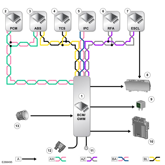
A = HARDWIRED: O = LIN: AX = FLEXRAY: AZ = HS CAN BODY SYSTEMS BUS: BA = HS CAN HMI SYSTEMS BUS: BL = HS CAN UNDERBODY (UN) SYSTEMS BUS.
| ITEM | DESCRIPTION |
|---|---|
| 1 | BCM/GWM |
| 2 | PCM |
| 3 | Integrated power brake with Anti-Lock Brake System Control Module (ABS) |
| 4 | Transmission Control Switch (TCS) |
| 5 | IPC |
| 6 | RFA |
| 7 | Electric Steering Column Lock (ESCL) (if equipped) |
| 8 | Electric Steering Column Lock (ESCL) ground - IPC |
| 9 | Fuel pump relay |
| 10 | Mobilization signal - PCM |
| 11 | Ground |
| 12 | Power supply |
| 13 | Ignition switch |