BATTERY AND CHARGING SYSTEM - GENERAL INFORMATION
BATTERY AND CHARGING SYSTEM - GENERAL INFORMATION
BATTERY SUPPORT UNIT CONNECTION PROCEDURE (G1915138)
GENERAL PROCEDURES
CONNECT
WARNINGS:
- Do not smoke or carry lighted tobacco or open flame of any type when working on or near the vehicles battery. Highly flammable vapors may be present and ignite. Failure to follow these instructions may result in personal injury.
- Avoid flames, sparks or lighted substances.
- Make sure that the battery is well ventilated while the battery support unit is connected.
- Switch off the current from the battery support unit before making any electrical connections or disconnections.
- The battery support unit must never be connected to both battery terminals. Always follow the safety warnings and documentation of the device that is being used.
- The battery support unit ground cable must always be connected to the vehicle last and disconnected first.
CAUTION:
Do not carry out any software downloads with the vehicle in transit mode or with the transit relay installed.
NOTES:
- This procedure covers connection instructions for the following vehicles;
- XE / X760
- XF / X260
- E-Pace / X540
- F-Pace / X761
- F-Type / X152
- XJ / X351
- XK / X150
- XF / X250
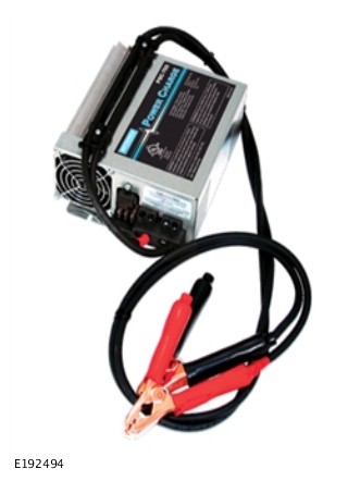
- This procedure covers operating instructions for the following battery support units;
- Traction BSU2-50 / 125
- Fronius ACCTIVA Professional Flash
- MIdtronics CX-Pro 50
- Traction MPL-50
- Midtronics PSC 700S
- WARNING:
Make sure that the cables are connected in the correct order.
NOTES:- This Step contains connection instructions for the following vehicles;
- XE / X760
- XF / X260
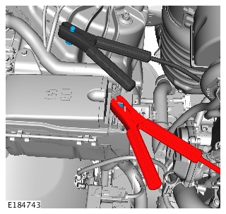
- Connect the battery support unit positive cable to the jump start positive terminal.
- Connect the battery support unit ground cable to the jump start ground terminal.
- WARNING:
Make sure that the cables are connected in the correct order.
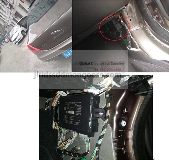
NOTES:- This Step contains connection instructions for the following vehicle;
- F-PACE / X761
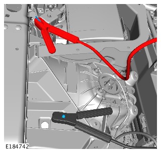
- Connect the battery support unit positive cable to the jump start positive terminal.
- Connect the battery support unit ground cable to the jump start ground terminal.
- WARNING:
Make sure that the cables are connected in the correct order.
NOTES:- This Step contains connection instructions for the following vehicle;
- E-PACE / X540
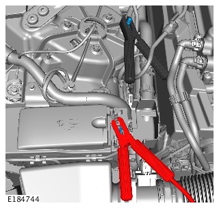
- Connect the battery support unit positive cable to the jump start positive terminal.
- Connect the battery support unit ground cable to the jump start ground terminal.
- WARNING:
Make sure that the cables are connected in the correct order.
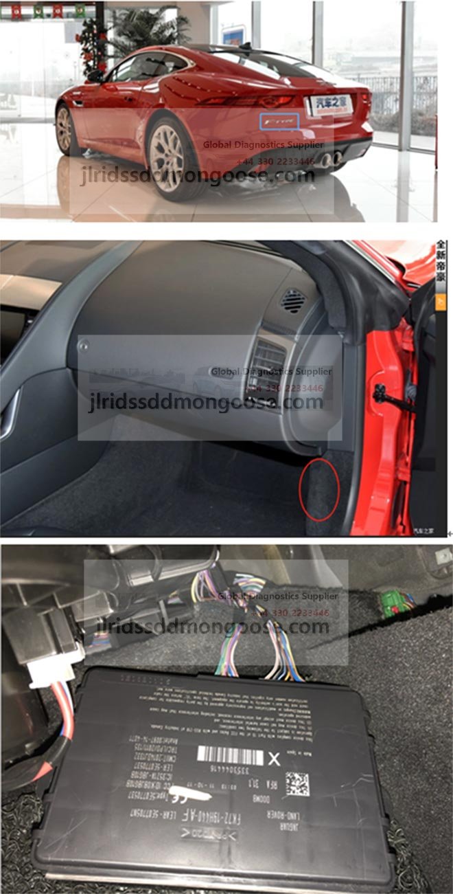
NOTES:- This Step contains connection instructions for the following vehicle;
- F-TYPE / X152
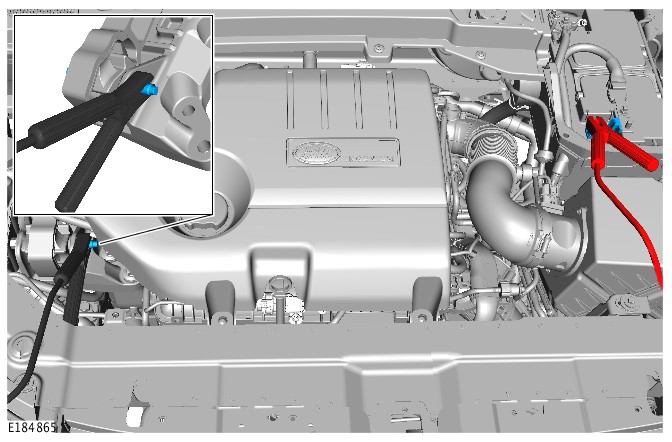
- Connect the battery support unit positive cable to the jump start positive terminal.
- Connect the battery support unit ground cable to the jump start ground terminal.
- WARNING:
Make sure that the cables are connected in the correct order.
NOTES:- This Step contains connection instructions for the following vehicle;
- XJ / X351
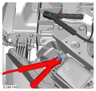
- Connect the battery support unit positive cable to the jump start positive terminal.
- Connect the battery support unit ground cable to the jump start ground terminal.
- WARNING:
Make sure that the cables are connected in the correct order.
NOTES:- This Step contains connection instructions for the following vehicle;
- XK / X150
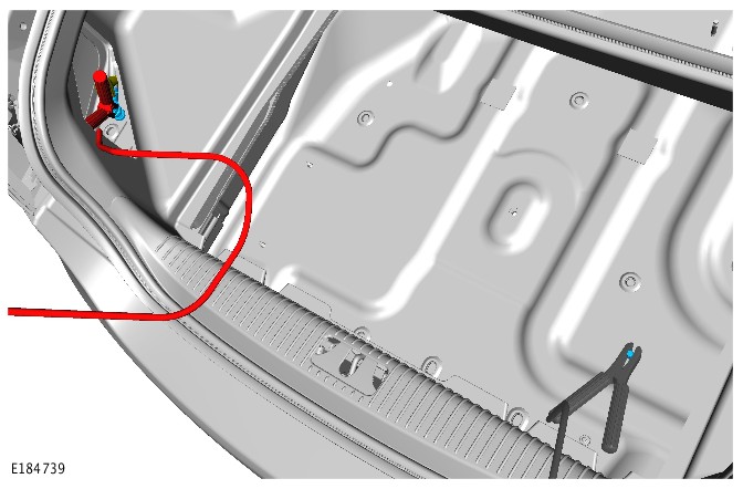
- Remove the left luggage compartment trim panel cover, to access the vehicle positive terminal. Position the terminal cover to one side.
- Lift the luggage compartment floor panel to reveal the spare wheel or trim. If equipped, lift the trim panel to access the ground terminal. Remove the protective cap from the ground terminal.
- Connect the battery support unit positive cable to the jump start positive terminal.
- Connect the battery support unit ground cable to the jump start ground terminal.
- WARNING:
Make sure that the cables are connected in the correct order.
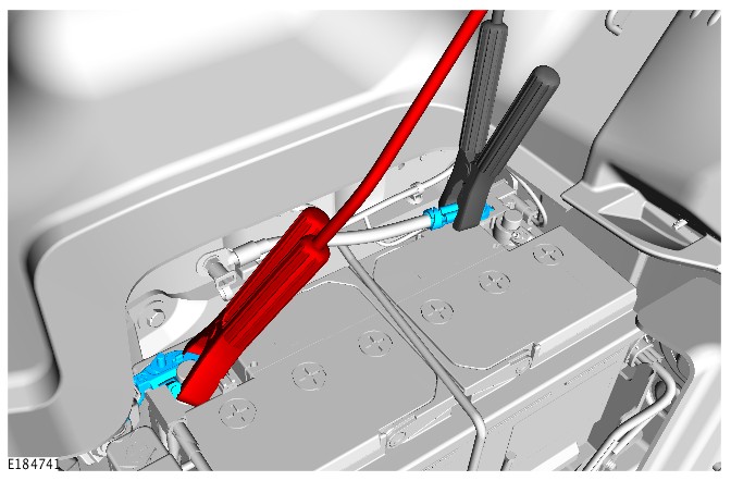
CAUTION:Do not connect the battery support unit ground cable directly to the battery ground terminal. The battery monitoring system (BMS) must be between the battery support unit ground cable clamp and the battery ground terminal.
NOTES:- Some variation in the illustration can occur, but the essential information is always correct.
- This Step contains connection instructions for the following vehicle;
- XF / X250
- Lift the luggage compartment floor panel for access.
- Remove the battery access panel.
- Connect the battery support unit positive cable to the primary battery positive terminal.
- Connect the battery support unit ground cable to the primary battery ground cable, as illustrated.
- CAUTION:
The Midtronics CX-Pro 50 can only support one vehicle at a time. It should not be used to support 2 vehicles at the same time.
NOTE:This Step contains operating instructions for the Midtronics CX-Pro 50 battery support unit.
- Connect the vehicle link cable to port 1 on the base of the battery support unit.
- NOTE:
Switch off any auxiliary systems, for example: headlamps, to reduce the electrical load on the battery support unit.
Switch the ignition ON, but do not start the engine.
- NOTE:
This Step contains operating instructions for the Midtronics CX-Pro 50 battery support unit.
- NOTE:
A green light will confirm the battery support unit is switched ON
Switch ON the battery support unit.
- NOTE:
An orange light indicates that power is being supplied to the vehicle.
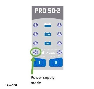
Use button 1 to select power supply mode.
- The battery support unit is now ready for a diagnostic session.
- NOTE:
- CAUTION:
The Traction Showroom Support Unit (SSU2) must not be used during diagnostic sessions. Only the Traction Battery Support Unit (BSU) / (BSU2) can be used.
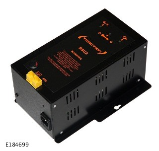
NOTE:This Step contains operating instructions for the Traction BSU2-50 / 125 battery support unit.
- NOTE:
Switch off any auxiliary systems, for example: headlamps, to reduce the electrical load on the battery support unit.
Switch the ignition ON, but do not start the engine.
- NOTE:
Confirm that all 3 lights are illuminated green before starting a diagnostic session.
Switch ON the battery support unit.
- The battery support unit is now ready for a diagnostic session.
- NOTE:
- NOTE:
This Step contains operating instructions for the Fronius ACCTIVA Professional Flash battery support unit.
- NOTE:
Switch off any auxiliary systems, for example: headlamps, to reduce the electrical load on the battery support unit.
Switch the ignition ON, but do not start the engine.
- NOTE:
The unit will indicate on screen that it is supplying current.
Switch ON the battery support unit and select external power supply mode (FSV / SPLY).
- The battery support unit is now ready for a diagnostic session.
- NOTE:
- NOTE:
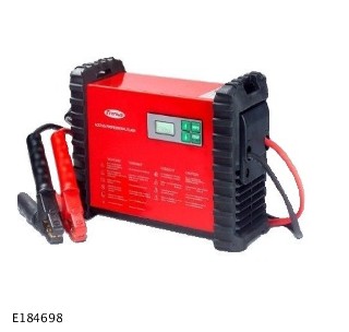
This Step contains operating instructions for the Traction MPL-50 battery support unit.
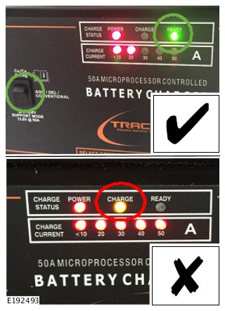
- CAUTIONS:
- The battery support unit must NOT be connected to an power supply at this stage.
- Charging mode must not be selected.
- NOTES:
- If the orange CHARGE lamp is illuminated for more than a few seconds;
- disconnect the battery support unit from the power supply
- disconnect the cables from the vehicle
- make sure the battery support mode is selected
- reconnect the cables to the vehicle
- reconnect the battery support unit to the power supply and confirm the green READY lamp is illuminated.
- The battery support unit is now ready for a diagnostic session.
- CAUTIONS:
- CAUTION:
The Midtronics PSC 700S is only to be used in markets with 120V power supply.
NOTE:This Step contains operating instructions for the Midtronics PSC 700S battery support unit.
- Connect the battery support unit to the power supply and switch the battery support unit ON.
- The battery support unit is now ready for a diagnostic session.