LTB00893 - Anti-Theft System Module Replacement Defender
LTB00893
TECHNICAL BULLETIN
25 JAN 2016

© Jaguar Land Rover Limited
All rights reserved.
SECTION:
419-00
SUBJECT/CONCERN:
Anti-Theft System Module Replacement
MARKETS:
All Except NAS
CONDITION SUMMARY:
SITUATION:
A customer may express a concern of a fault with the alarm system.
If the Anti-Theft System module is at fault a technician will find the part is no longer available.
CAUSE:
The previous level part is no longer available.
Suggested Customer Concern Code - JH6.
ACTION:
Should a customer express this concern, follow the Service Instruction below.
PARTS:
| PART NUMBER | DESCRIPTION | QUANTITY |
|---|---|---|
| LR066426 | Anti-Theft System Module (No central locking) | 1 |
| LR066837 | Anti-Theft System Module (With central locking) | 1 |
| LR062109 | Anti-Theft System transceiver | 1 |
| LR012397 | Radio Frequency Receiver (RFR) 315Mhz | 1 |
| LR012398 | Radio Frequency Receiver (RFR) 433Mhz | 1 |
| LR055983 | Smart Key 315Mhz | 2 |
| LR067197 | Smart Key 433Mhz | 2 |
| LR076021 | Wiring Harness | 1 |
TOOLS:
DVD143.02 AND CALIBRATION FILE 218 LOADED OR LATER
JLR approved diagnostic tool
JLR approved battery support unit
418-S549
Wiring harness repair kit
WARRANTY:
NOTES:
- Repair procedures are under constant review, and therefore times are subject to change; those quoted here must be taken as guidance only. Use TOPIx to obtain the latest repair time.
- The JLR claims submission system requires the use of causal part numbers. Labor only claims must show the causal part number with a quantity of zero.
| DESCRIPTION | SRO | TIME (HOURS) | CONDITION CODE | CAUSAL PART |
| Anti-Theft System Module - Renew | 86.77.89.52 | 0.7 | 42 | LR045287 |
| Key Programming | 86.91.06 | 0.1 | 42 | LR045287 |
NOTE:
Normal Warranty procedures apply.
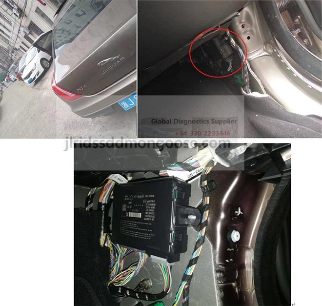
COMPONENT LOCATION
- NOTE:
RHD shown, LHD is the opposite.
The illustration shows the location of the Anti-Theft System Module.
SERVICE INSTRUCTION:
2007-2011 MY Vehicles
- Remove the existing anti-theft system transceiver (see TOPIx Workshop Manual, Section 419-01B).
- Install the new anti-theft system transceiver (see TOPIx Workshop Manual, Section 419-01B).
- Remove the existing anti-theft system module (see TOPIx Workshop Manual, Section 419-01).
Using the Velcro® pad supplied with the kit, install the Radio Frequency Receiver (RFR) onto the new anti-theft system module.
Install the RFR onto the bulkhead using the Velcro® pad supplied with the kit.
- Install the anti-theft system module (see TOPIx Workshop Manual, Section 419-01).
Locate the anti-theft system module ground (C0057 pin 11), cut this black wire leaving sufficient space for a splice connection.
- Prepare both ends of the cut black wire for a crimp connector.
Using the RFR harness from the bag labelled 'Loose items' create a spliced crimp joint with the black wires from C0057 position 11, both ends of the cut wire from step 7 need to be crimped into the same end of the splice joint. This provides the RFR with a ground connection.
Install the white wire from the RFR harness into position 22 on C0061.
De-pin the brown/pink wire going into cavity 1 of C0583.
- Cut off the terminal.
- Strip back the cut lead.
Using the supplied yellow connector, splice a new labelled lead 5 from the bag labelled (loose items) splice the two leads together.
- Locate new labelled lead 4 from the bag labelled (loose items) into cavity 1 of C0583.
- Then insert the new lead 6 into Cavity 9 of C0583 (this supplies feed to cavity 9 in the fuse box under the steering wheel for RFR).
- Take new labelled lead 3 supplied in kit, and connect this to cavity 10 of C0583.
- Connect the other end of this lead to pin 3 on the RFR connector C3788.
- Install the 10 amp fuse between cavities 9 & 10, this now becomes fuse 32.
- To install, reverse the removal procedure.
LHD vehicles
RHD vehicles
Ground connection
Signal wire
Power Feeds
SERVICE INSTRUCTION:
2012-2013 MY Vehicles
- Remove the existing anti-theft system transceiver (see TOPIx Workshop Manual, Section 419-01B).
- Install the new anti-theft system transceiver (see TOPIx Workshop Manual, Section 419-01B).
- Remove the existing anti-theft system module (see TOPIx Workshop Manual, Section 419-01).
- Install the anti-theft system module (see TOPIx Workshop Manual, Section 419-01).
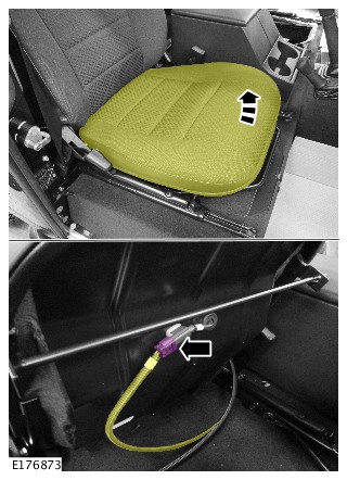
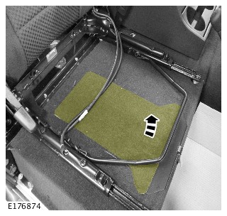
Remove the under seat fuse box cover.
In some instances on 12 model year vehicles, there may be a white/green wire in the Main/Fuse Box connector C3766 cavity 11. This wire needs to be rerouted.
- Carry out Step 10.
- However, If there is no wire in C3766 cavity 11, carry out Step 11.
De-pin existing White/Green wire going into cavity 11 of C3766.
- cut off terminal
- strip wire end.
- Using Blue PIDG splice, splice together with new labelled Lead 13 (White/Green) wire provided.
- populate pin 24 of C3766.
- Re-pin Pin 11 C3766 with the new terminated end of Lead 12 (purple/brown).
- Connect the other end to pin 3 of the RFR connector C3788.
De-pin cavity 3 of C3769.
- De-pin cavity 26 of C0570B.
- Discard both of these (using tape, insulate each end and secure as this wire is now dead).
Using Bag 3
- Splice Joint 2 (SJ2, Lead 14,15,16 all brown leads), connect lead 16 to cavity 3 of C3769,
- Connect lead 14 to cavity 4 of C0570D
- Connect Lead 15 to cavity 26 of C0570B.
- If there is no wire currently in cavity 11 of C3767 go to Step 15
- If however, there is a white/green wire already in cavity 11 of C3767 go to Step 16
Using new labelled Lead 17 provided, connect one end to cavity 11 of C3767, and other end to cavity 8 of C0570D.
- De-pin this wire, cut off the terminal and strip the end, using Blue PIDG splice, splice this wire to New labelled Lead 18 supplied and connect this new lead into cavity 24 of C3767.
- If there is a white/green wire already in cavity 11 of C3767, then using new labelled lead 17 provided, re-pin C3767 cavity 11 then connect the other end to C0570D cavity 8.
Now fit the 10amp fuse supplied between cavities 4 and 8 of C0570D Fusebox Eng 1 connector.
PROGRAMMING THE SMART KEY
For all vehicles.
- Connect the JLR approved battery support unit.
- Connect the JLR approved diagnostic tool to the vehicle and begin a new diagnostic session by reading the Vehicle Identification Number (VIN) for the current vehicle and initiating the data collect sequence.
- Follow the prompts.
- If the hyperlink is not available, the application can be found as follows:
- Select Service Functions session type
- Run :Security - Key programming.
- When all of the tasks are complete, exit the current session by selecting the Session tab and then select the Close Session option.
- Disconnect the JLR approved diagnostic tool and battery support unit.