| B0001-11 | Driver Frontal Stage 1 Deployment Control - Circuit short to ground | NOTES:
- Circuit reference - Driver Airbag Stage 1 Deployment Control Feed -
- Circuit reference - Driver Airbag Stage 1 Deployment Control Return -
- Driver airbag (stage 1) circuit short circuit to ground
| NOTE:
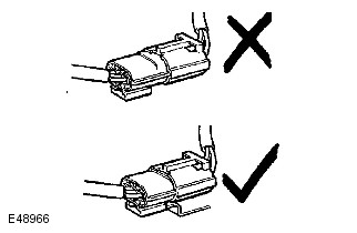
The deployable device connector has a locking plunger (orange tab) which should only fully lock when the two connectors are securely mated, male to female. If the plunger can move to the locked position easily when not mated (ie: using reasonable pressure), then this indicates that the connector is damaged. Install a new wiring harness as necessary.
- Refer to the electrical circuit diagrams and check the driver airbag (stage 1) circuit for short circuit to ground. Check for intermittent short circuit to ground within the clockspring by rotating the steering column during the checks
|
| B0001-12 | Driver Frontal Stage 1 Deployment Control - Circuit short to battery | NOTES:
- Circuit reference - Driver Airbag Stage 1 Deployment Control Feed -
- Circuit reference - Driver Airbag Stage 1 Deployment Control Return -
- Driver airbag (stage 1) circuit short to power
| NOTE:
The deployable device connector has a locking plunger (orange tab) which should only fully lock when the two connectors are securely mated, male to female. If the plunger can move to the locked position easily when not mated (ie: using reasonable pressure), then this indicates that the connector is damaged. Install a new wiring harness as necessary.
- Refer to the electrical circuit diagrams and check the driver airbag (stage 1) circuit for short circuit to power. Check for intermittent short circuit to power within the clockspring by rotating the steering column during the checks
|
| B0001-13 | Driver Frontal Stage 1 Deployment Control - Circuit open | NOTES:
- Circuit reference - Driver Airbag Stage 1 Deployment Control Feed -
- Circuit reference - Driver Airbag Stage 1 Deployment Control Return -
- Driver airbag (stage 1) circuit open circuit, high resistance
- Driver airbag (stage 1) connector damaged
| WARNING:
Do not measure the resistance of a deployable device using any other method than that described below.
NOTES:
- The deployable device connector has a locking plunger (orange tab) which should only fully lock when the two connectors are securely mated, male to female. If the plunger can move to the locked position easily when not mated (ie: using reasonable pressure), then this indicates that the connector is damaged. Install a new wiring harness as necessary.
- Driver airbag (stage 1) resistance specification should be greater than 1.70 ohms and less than 3.68 ohms at -40°C to 85°C.
- Using the Jaguar Land Rover approved diagnostic equipment, check datalogger signal - Deployment Control 1 Resistance (0x5B04). Refer to the electrical circuit diagrams and check the driver airbag (stage 1) circuit for open circuit, high resistance. Check for intermittent open circuit within the clockspring by rotating the steering column during the checks
- Disconnect the driver airbag (stage 1) connector and apply light pressure to the connector plunger. If the plunger moves to the engaged position the connector is damaged. Install a new wiring harness as necessary
- Using the Jaguar Land Rover approved diagnostic equipment, clear the DTCs and retest
|
| B0001-1A | Driver Frontal Stage 1 Deployment Control - Circuit resistance below threshold | NOTES:
- Circuit reference - Driver Airbag Stage 1 Deployment Control Feed -
- Circuit reference - Driver Airbag Stage 1 Deployment Control Return -
- Driver airbag (stage 1) connector plunger not engaged
- Driver airbag (stage 1) connector damaged
- Driver airbag (stage 1) circuit short circuit between power and ground
| WARNING:
Do not measure the resistance of a deployable device using any other method than that described below.
NOTES:
- The deployable device connector has a locking plunger (orange tab) which should only fully lock when the two connectors are securely mated, male to female. If the plunger can move to the locked position easily when not mated (ie: using reasonable pressure), then this indicates that the connector is damaged. Install a new wiring harness as necessary.
- A shorting bar inside the connector (deployable device side) intentionally creates a short circuit until the wiring harness connector is installed AND the plunger is engaged.
- Driver airbag (stage 1) resistance specification should be greater than 1.70 ohms and less than 3.68 ohms at -40°C to 85°C.
- Using the Jaguar Land Rover approved diagnostic equipment, check datalogger signal - Deployment Control 1 Resistance (0x5B04). If the resistance is too low, disconnect and reconnect the driver airbag (stage 1) connector, making sure that the connector plunger is correctly engaged. Clear the DTCs and retest
- Disconnect the driver airbag (stage 1) connector and apply light pressure to the connector plunger. If the plunger moves to the engaged position the connector is damaged. Install a new wiring harness as necessary
- Refer to the electrical circuit diagrams and check the driver airbag (stage 1) circuit for short circuit between power and ground. Check for intermittent short circuit within the clockspring by rotating the steering column during the checks
- Using the Jaguar Land Rover approved diagnostic equipment, clear the DTCs and retest
|
| B0001-2B | Driver Frontal Stage 1 Deployment Control - Signal cross coupled | NOTES:
- Circuit reference - Driver Airbag Stage 1 Deployment Control Feed -
- Circuit reference - Driver Airbag Stage 1 Deployment Control Return -
- Driver airbag (stage 1) circuit short circuit to another restraints circuit
| NOTE:
The deployable device connector has a locking plunger (orange tab) which should only fully lock when the two connectors are securely mated, male to female. If the plunger can move to the locked position easily when not mated (ie: using reasonable pressure), then this indicates that the connector is damaged. Install a new wiring harness as necessary.
- Refer to the electrical circuit diagrams and check the driver airbag (stage 1) circuit for short circuit to another restraints circuit. Check for intermittent short circuit within the clockspring by rotating the steering column during the checks
|
| B0001-56 | Driver Frontal Stage 1 Deployment Control - Invalid / incomplete configuration | - Car configuration file mismatch with vehicle specification
| NOTE:
After updating the car configuration file, set the ignition to on and wait 30 seconds before clearing the DTCs.
- Using the Jaguar Land Rover approved diagnostic equipment, check and update the car configuration file as necessary. Clear the DTCs and retest
|
| B0002-11 | Driver Frontal Stage 2 Deployment Control - Circuit short to ground | NOTES:
- Circuit reference - Driver Airbag Stage 2 Deployment Control Feed -
- Circuit reference - Driver Airbag Stage 2 Deployment Control Return -
- Driver airbag (stage 2) circuit short circuit to ground
| NOTE:
The deployable device connector has a locking plunger (orange tab) which should only fully lock when the two connectors are securely mated, male to female. If the plunger can move to the locked position easily when not mated (ie: using reasonable pressure), then this indicates that the connector is damaged. Install a new wiring harness as necessary.
- Refer to the electrical circuit diagrams and check the driver airbag (stage 2) circuit for short circuit to ground. Check for intermittent short circuit to ground within the clockspring by rotating the steering column during the checks
|
| B0002-12 | Driver Frontal Stage 2 Deployment Control - Circuit short to battery | NOTES:
- Circuit reference - Driver Airbag Stage 2 Deployment Control Feed -
- Circuit reference - Driver Airbag Stage 2 Deployment Control Return -
- Driver airbag (stage 2) circuit short to power
| NOTE:
The deployable device connector has a locking plunger (orange tab) which should only fully lock when the two connectors are securely mated, male to female. If the plunger can move to the locked position easily when not mated (ie: using reasonable pressure), then this indicates that the connector is damaged. Install a new wiring harness as necessary.
- Refer to the electrical circuit diagrams and check the driver airbag (stage 2) circuit for short circuit to power. Check for intermittent short circuit to power within the clockspring by rotating the steering column during the checks
|
| B0002-13 | Driver Frontal Stage 2 Deployment Control - Circuit open | NOTES:
- Circuit reference - Driver Airbag Stage 2 Deployment Control Feed -
- Circuit reference - Driver Airbag Stage 2 Deployment Control Return -
- Driver airbag (stage 2) circuit open circuit, high resistance
- Driver airbag (stage 2) connector damaged
| WARNING:
Do not measure the resistance of a deployable device using any other method than that described below.
NOTES:
- The deployable device connector has a locking plunger (orange tab) which should only fully lock when the two connectors are securely mated, male to female. If the plunger can move to the locked position easily when not mated (ie: using reasonable pressure), then this indicates that the connector is damaged. Install a new wiring harness as necessary.
- Driver airbag (stage 2) resistance specification should be greater than 1.70 ohms and less than 3.68 ohms at -40°C to 85°C.
- Using the Jaguar Land Rover approved diagnostic equipment, check datalogger signal - Deployment Control 3 Resistance (0x5B06). Refer to the electrical circuit diagrams and check the driver airbag (stage 2) circuit for open circuit, high resistance. Check for intermittent open circuit within the clockspring by rotating the steering column during the checks
- Disconnect the driver airbag (stage 2) connector and apply light pressure to the connector plunger. If the plunger moves to the engaged position the connector is damaged. Install a new wiring harness as necessary
- Using the Jaguar Land Rover approved diagnostic equipment, clear the DTCs and retest
|
| B0002-1A | Driver Frontal Stage 2 Deployment Control - Circuit resistance below threshold | NOTES:
- Circuit reference - Driver Airbag Stage 2 Deployment Control Feed -
- Circuit reference - Driver Airbag Stage 2 Deployment Control Return -
- Driver airbag (stage 2) connector plunger not engaged
- Driver airbag (stage 2) connector damaged
- Driver airbag (stage 2) circuit short circuit between power and ground
| WARNING:
Do not measure the resistance of a deployable device using any other method than that described below.
NOTES:
- The deployable device connector has a locking plunger (orange tab) which should only fully lock when the two connectors are securely mated, male to female. If the plunger can move to the locked position easily when not mated (ie: using reasonable pressure), then this indicates that the connector is damaged. Install a new wiring harness as necessary.
- A shorting bar inside the connector (deployable device side) intentionally creates a short circuit until the wiring harness connector is installed AND the plunger is engaged.
- Driver airbag (stage 2) resistance specification should be greater than 1.70 ohms and less than 3.68 ohms at -40°C to 85°C.
- Using the Jaguar Land Rover approved diagnostic equipment, check datalogger signal - Deployment Control 3 Resistance (0x5B06). If the resistance is too low, disconnect and reconnect the driver airbag (stage 2) connector, making sure that the connector plunger is correctly engaged. Clear the DTCs and retest
- Disconnect the driver airbag (stage 2) connector and apply light pressure to the connector plunger. If the plunger moves to the engaged position the connector is damaged. Install a new wiring harness as necessary
- Refer to the electrical circuit diagrams and check the driver airbag (stage 2) circuit for short circuit between power and ground. Check for intermittent short circuit within the clockspring by rotating the steering column during the checks
- Using the Jaguar Land Rover approved diagnostic equipment, clear the DTCs and retest
|
| B0002-2B | Driver Frontal Stage 2 Deployment Control - Signal cross coupled | NOTES:
- Circuit reference - Driver Airbag Stage 2 Deployment Control Feed -
- Circuit reference - Driver Airbag Stage 2 Deployment Control Return -
- Driver airbag (stage 2) circuit short circuit to another restraints circuit
| NOTE:
The deployable device connector has a locking plunger (orange tab) which should only fully lock when the two connectors are securely mated, male to female. If the plunger can move to the locked position easily when not mated (ie: using reasonable pressure), then this indicates that the connector is damaged. Install a new wiring harness as necessary.
- Refer to the electrical circuit diagrams and check the driver airbag (stage 2) circuit for short circuit to another restraints circuit. Check for intermittent short circuit within the clockspring by rotating the steering column during the checks
|
| B0002-56 | Driver Frontal Stage 2 Deployment Control - Invalid / incomplete configuration | - Car configuration file mismatch with vehicle specification
| NOTE:
After updating the car configuration file, set the ignition to on and wait 30 seconds before clearing the DTCs.
- Using the Jaguar Land Rover approved diagnostic equipment, check and update the car configuration file as necessary. Clear the DTCs and retest
|
| B0005-11 | Collapsible Steering Column Deployment Control - Circuit short to ground | NOTES:
- Circuit reference - Pyrotechnic Brake Pedal Deployment Control Feed -
- Circuit reference - Pyrotechnic Brake Pedal Deployment Control Return -
- Steering column collapse actuator circuit short circuit to ground
| NOTES:
- The deployable device connector has a locking plunger (orange tab) which should only fully lock when the two connectors are securely mated, male to female. If the plunger can move to the locked position easily when not mated (ie: using reasonable pressure), then this indicates that the connector is damaged. Install a new wiring harness as necessary.
- The circuit reference is common for both steering column collapse actuator and brake pedal arm emergency release deployment control.
- Refer to the electrical circuit diagrams and check the steering column collapse actuator circuit for short circuit to ground
|
| B0005-12 | Collapsible Steering Column Deployment Control - Circuit short to battery | NOTES:
- Circuit reference - Pyrotechnic Brake Pedal Deployment Control Feed -
- Circuit reference - Pyrotechnic Brake Pedal Deployment Control Return -
- Steering column collapse actuator circuit short circuit to power
| NOTES:
- The deployable device connector has a locking plunger (orange tab) which should only fully lock when the two connectors are securely mated, male to female. If the plunger can move to the locked position easily when not mated (ie: using reasonable pressure), then this indicates that the connector is damaged. Install a new wiring harness as necessary.
- The circuit reference is common for both steering column collapse actuator and brake pedal arm emergency release deployment control.
- Refer to the electrical circuit diagrams and check the steering column collapse actuator circuit for short circuit to power
|
| B0005-13 | Collapsible Steering Column Deployment Control - Circuit open | NOTES:
- Circuit reference - Pyrotechnic Brake Pedal Deployment Control Feed -
- Circuit reference - Pyrotechnic Brake Pedal Deployment Control Return -
- Steering column collapse actuator circuit open circuit, high resistance
- Steering column collapse actuator connector damaged
- Steering column collapse actuator internal failure
| WARNING:
Do not measure the resistance of a deployable device using any other method than that described below.
NOTES:
- The deployable device connector has a locking plunger (orange tab) which should only fully lock when the two connectors are securely mated, male to female. If the plunger can move to the locked position easily when not mated (ie: using reasonable pressure), then this indicates that the connector is damaged. Install a new wiring harness as necessary.
- Steering column collapse actuator resistance specification should be greater than 1.70 ohms and less than 3.28 ohms at -40°C to 85°C.
- The circuit reference is common for both steering column collapse actuator and brake pedal arm emergency release deployment control.
- Using the Jaguar Land Rover approved diagnostic equipment, check datalogger signal - Deployment Control 4 Resistance (0x5B07). Refer to the electrical circuit diagrams and check the steering column collapse actuator circuit for open circuit, high resistance
- Disconnect the steering column collapse actuator connector and apply light pressure to the connector plunger. If the plunger moves to the engaged position the connector is damaged. Install a new wiring harness as necessary
- Using the Jaguar Land Rover approved diagnostic equipment, clear the DTCs and retest. If the fault persists, install a new steering column collapse actuator
|
| B0005-1A | Collapsible Steering Column Deployment Control - Circuit resistance below threshold | NOTES:
- Circuit reference - Pyrotechnic Brake Pedal Deployment Control Feed -
- Circuit reference - Pyrotechnic Brake Pedal Deployment Control Return -
- Steering column collapse actuator connector plunger not engaged
- Steering column collapse actuator connector damaged
- Steering column collapse actuator circuit short circuit between power and ground
- Steering column collapse actuator internal failure
| WARNING:
Do not measure the resistance of a deployable device using any other method than that described below.
NOTES:
- The deployable device connector has a locking plunger (orange tab) which should only fully lock when the two connectors are securely mated, male to female. If the plunger can move to the locked position easily when not mated (ie: using reasonable pressure), then this indicates that the connector is damaged. Install a new wiring harness as necessary.
- A shorting bar inside the connector (deployable device side) intentionally creates a short circuit until the wiring harness connector is installed AND the plunger is engaged.
- Steering column collapse actuator resistance specification should be greater than 1.70 ohms and less than 3.28 ohms at -40°C to 85°C.
- The circuit reference is common for both steering column collapse actuator and brake pedal arm emergency release deployment control.
- Using the Jaguar Land Rover approved diagnostic equipment, check datalogger signal - Deployment Control 4 Resistance (0x5B07). If the resistance is too low, disconnect and reconnect the steering column collapse actuator connector, making sure that the connector plunger is correctly engaged. Clear the DTCs and retest
- Disconnect the steering column collapse actuator connector and apply light pressure to the connector plunger. If the plunger moves to the engaged position the connector is damaged. Install a new wiring harness as necessary
- Refer to the electrical circuit diagrams and check the steering column collapse actuator circuit for short circuit between power and ground
- Using the Jaguar Land Rover approved diagnostic equipment, clear the DTCs and retest. If the fault persists, install a new steering column collapse actuator
|
| B0005-2B | Collapsible Steering Column Deployment Control - Signal cross coupled | NOTES:
- Circuit reference - Pyrotechnic Brake Pedal Deployment Control Feed -
- Circuit reference - Pyrotechnic Brake Pedal Deployment Control Return -
- Steering column collapse actuator circuit short circuit to another restraints circuit
| NOTES:
- The deployable device connector has a locking plunger (orange tab) which should only fully lock when the two connectors are securely mated, male to female. If the plunger can move to the locked position easily when not mated (ie: using reasonable pressure), then this indicates that the connector is damaged. Install a new wiring harness as necessary.
- The circuit reference is common for both steering column collapse actuator and brake pedal arm emergency release deployment control.
- Refer to the electrical circuit diagrams and check the steering column collapse actuator circuit for short circuit to another restraints circuit
|
| B0005-56 | Collapsible Steering Column Deployment Control - Invalid / incomplete configuration | - Car configuration file mismatch with vehicle specification
| NOTE:
After updating the car configuration file, set the ignition to on and wait 30 seconds before clearing the DTCs.
- Using the Jaguar Land Rover approved diagnostic equipment, check and update the car configuration file as necessary. Clear the DTCs and retest
|
| B0010-11 | Passenger Frontal Stage 1 Deployment Control - Circuit short to ground | NOTES:
- Circuit reference - Passenger Airbag Stage 1 Deployment Control Feed -
- Circuit reference - Passenger Airbag Stage 1 Deployment Control Return -
- Passenger airbag (stage 1) circuit short to ground
| NOTE:
The deployable device connector has a locking plunger (orange tab) which should only fully lock when the two connectors are securely mated, male to female. If the plunger can move to the locked position easily when not mated (ie: using reasonable pressure), then this indicates that the connector is damaged. Install a new wiring harness as necessary.
- Refer to the electrical circuit diagrams and check the passenger airbag (stage 1) circuit for short circuit to ground
|
| B0010-12 | Passenger Frontal Stage 1 Deployment Control - Circuit short to battery | NOTES:
- Circuit reference - Passenger Airbag Stage 1 Deployment Control Feed -
- Circuit reference - Passenger Airbag Stage 1 Deployment Control Return -
- Passenger airbag (stage 1) circuit short to power
| NOTE:
The deployable device connector has a locking plunger (orange tab) which should only fully lock when the two connectors are securely mated, male to female. If the plunger can move to the locked position easily when not mated (ie: using reasonable pressure), then this indicates that the connector is damaged. Install a new wiring harness as necessary.
- Refer to the electrical circuit diagrams and check the passenger airbag (stage 1) circuit for short circuit to power
|
| B0010-13 | Passenger Frontal Stage 1 Deployment Control - Circuit open | NOTES:
- Circuit reference - Passenger Airbag Stage 1 Deployment Control Feed -
- Circuit reference - Passenger Airbag Stage 1 Deployment Control Return -
- Passenger airbag (stage 1) circuit open circuit, high resistance
- Passenger airbag (stage 1) connector damaged
| WARNING:
Do not measure the resistance of a deployable device using any other method than that described below.
NOTES:
- The deployable device connector has a locking plunger (orange tab) which should only fully lock when the two connectors are securely mated, male to female. If the plunger can move to the locked position easily when not mated (ie: using reasonable pressure), then this indicates that the connector is damaged. Install a new wiring harness as necessary.
- Passenger airbag (stage 1) resistance specification should be greater than 1.70 ohms and less than 3.28 ohms at -40°C to 85°C.
- Using the Jaguar Land Rover approved diagnostic equipment, check datalogger signal - Deployment Control 0 Resistance (0x5B03). Refer to the electrical circuit diagrams and check the passenger airbag (stage 1) circuit for open circuit, high resistance
- Disconnect the passenger airbag (stage 1) connector and apply light pressure to the connector plunger. If the plunger moves to the engaged position the connector is damaged. Install a new wiring harness as necessary
- Using the Jaguar Land Rover approved diagnostic equipment, clear the DTCs and retest
|
| B0010-1A | Passenger Frontal Stage 1 Deployment Control - Circuit resistance below threshold | NOTES:
- Circuit reference - Passenger Airbag Stage 1 Deployment Control Feed -
- Circuit reference - Passenger Airbag Stage 1 Deployment Control Return -
- Passenger airbag (stage 1) connector plunger not engaged
- Passenger airbag (stage 1) connector damaged
- Passenger airbag (stage 1) circuit short circuit between power and ground
| WARNING:
Do not measure the resistance of a deployable device using any other method than that described below.
NOTES:
- The deployable device connector has a locking plunger (orange tab) which should only fully lock when the two connectors are securely mated, male to female. If the plunger can move to the locked position easily when not mated (ie: using reasonable pressure), then this indicates that the connector is damaged. Install a new wiring harness as necessary.
- A shorting bar inside the connector (deployable device side) intentionally creates a short circuit until the wiring harness connector is installed AND the plunger is engaged.
- Passenger airbag (stage 1) resistance specification should be greater than 1.70 ohms and less than 3.28 ohms at -40°C to 85°C.
- Using the Jaguar Land Rover approved diagnostic equipment, check datalogger signal - Deployment Control 0 Resistance (0x5B03). If the resistance is too low, disconnect and reconnect the passenger airbag (stage 1) connector, making sure that the connector plunger is correctly engaged. Clear the DTCs and retest
- Disconnect the passenger airbag (stage 1) connector and apply light pressure to the connector plunger. If the plunger moves to the engaged position the connector is damaged. Install a new wiring harness as necessary
- Refer to the electrical circuit diagrams and check the passenger airbag (stage 1) circuit for short circuit between power and ground
- Using the Jaguar Land Rover approved diagnostic equipment, clear the DTCs and retest
|
| B0010-2B | Passenger Frontal Stage 1 Deployment Control - Signal cross coupled | NOTES:
- Circuit reference - Passenger Airbag Stage 1 Deployment Control Feed -
- Circuit reference - Passenger Airbag Stage 1 Deployment Control Return -
- Passenger airbag (stage 1) circuit short circuit to another restraints circuit
| NOTE:
The deployable device connector has a locking plunger (orange tab) which should only fully lock when the two connectors are securely mated, male to female. If the plunger can move to the locked position easily when not mated (ie: using reasonable pressure), then this indicates that the connector is damaged. Install a new wiring harness as necessary.
- Refer to the electrical circuit diagrams and check the passenger airbag (stage 1) circuit for short circuit to another restraints circuit
|
| B0010-56 | Passenger Frontal Stage 1 Deployment Control - Invalid / incomplete configuration | - Car configuration file mismatch with vehicle specification
| NOTE:
After updating the car configuration file, set the ignition to on and wait 30 seconds before clearing the DTCs.
- Using the Jaguar Land Rover approved diagnostic equipment, check and update the car configuration file as necessary. Clear the DTCs and retest
|
| B0011-11 | Passenger Frontal Stage 2 Deployment Control - Circuit short to ground | - Passenger airbag (stage 2) circuit short to ground
| NOTE:
The deployable device connector has a locking plunger (orange tab) which should only fully lock when the two connectors are securely mated, male to female. If the plunger can move to the locked position easily when not mated (ie: using reasonable pressure), then this indicates that the connector is damaged. Install a new wiring harness as necessary.
- Refer to the electrical circuit diagrams and check the passenger airbag (stage 2) circuit for short circuit to ground
|
| B0011-12 | Passenger Frontal Stage 2 Deployment Control - Circuit short to battery | - Passenger airbag (stage 2) circuit short to power
| NOTE:
The deployable device connector has a locking plunger (orange tab) which should only fully lock when the two connectors are securely mated, male to female. If the plunger can move to the locked position easily when not mated (ie: using reasonable pressure), then this indicates that the connector is damaged. Install a new wiring harness as necessary.
- Refer to the electrical circuit diagrams and check the passenger airbag (stage 2) circuit for short circuit to power
|
| B0011-13 | Passenger Frontal Stage 2 Deployment Control - Circuit open | - Passenger airbag (stage 2) circuit open circuit, high resistance
- Passenger airbag (stage 2) connector damaged
| WARNING:
Do not measure the resistance of a deployable device using any other method than that described below.
NOTES:
- The deployable device connector has a locking plunger (orange tab) which should only fully lock when the two connectors are securely mated, male to female. If the plunger can move to the locked position easily when not mated (ie: using reasonable pressure), then this indicates that the connector is damaged. Install a new wiring harness as necessary.
- Passenger airbag (stage 2) resistance specification should be greater than 1.70 ohms and less than 3.28 ohms at -40°C to 85°C.
- Using the Jaguar Land Rover approved diagnostic equipment, check datalogger signal - Deployment Control 2 Resistance (0x5B05). Refer to the electrical circuit diagrams and check the passenger airbag (stage 2) circuit for open circuit, high resistance
- Disconnect the passenger airbag (stage 2) connector and apply light pressure to the connector plunger. If the plunger moves to the engaged position the connector is damaged. Install a new wiring harness as necessary
- Using the Jaguar Land Rover approved diagnostic equipment, clear the DTCs and retest
|
| B0011-1A | Passenger Frontal Stage 2 Deployment Control - Circuit resistance below threshold | - Passenger airbag (stage 2) connector plunger not engaged
- Passenger airbag (stage 2) connector damaged
- Passenger airbag (stage 2) circuit short circuit between power and ground
| WARNING:
Do not measure the resistance of a deployable device using any other method than that described below.
NOTES:
- The deployable device connector has a locking plunger (orange tab) which should only fully lock when the two connectors are securely mated, male to female. If the plunger can move to the locked position easily when not mated (ie: using reasonable pressure), then this indicates that the connector is damaged. Install a new wiring harness as necessary.
- A shorting bar inside the connector (deployable device side) intentionally creates a short circuit until the wiring harness connector is installed AND the plunger is engaged.
- Passenger airbag (stage 2) resistance specification should be greater than 1.70 ohms and less than 3.28 ohms at -40°C to 85°C.
- Using the Jaguar Land Rover approved diagnostic equipment, check datalogger signal - Deployment Control 2 Resistance (0x5B05). If the resistance is too low, disconnect and reconnect the passenger airbag (stage 2) connector, making sure that the connector plunger is correctly engaged. Clear the DTCs and retest
- Disconnect the passenger airbag (stage 2) connector and apply light pressure to the connector plunger. If the plunger moves to the engaged position the connector is damaged. Install a new wiring harness as necessary
- Refer to the electrical circuit diagrams and check the passenger airbag (stage 2) circuit for short circuit between power and ground
- Using the Jaguar Land Rover approved diagnostic equipment, clear the DTCs and retest
|
| B0011-2B | Passenger Frontal Stage 2 Deployment Control - Signal cross coupled | - Passenger airbag (stage 2) circuit short circuit to another restraints circuit
| NOTE:
The airbag connector has a locking plunger (orange tab) which should only fully lock when the two connectors are securely mated, male to female. If the plunger can move to the locked position easily when not mated (ie: using reasonable pressure), then this indicates that the connector is damaged. Install a new wiring harness as necessary.
- Refer to the electrical circuit diagrams and check the passenger airbag (stage 2) circuit for short circuit to another restraints circuit
|
| B0011-56 | Passenger Frontal Stage 2 Deployment Control - Invalid / incomplete configuration | - Car configuration file mismatch with vehicle specification
| NOTE:
After updating the car configuration file, set the ignition to on and wait 30 seconds before clearing the DTCs.
- Using the Jaguar Land Rover approved diagnostic equipment, check and update the car configuration file as necessary. Clear the DTCs and retest
|
| B0013-11 | Passenger Knee Bolster Deployment Control - Circuit short to ground | - Passenger knee bolster deployment circuit short circuit to ground
| - Refer to the electrical circuit diagrams and check the passenger knee bolster deployment circuit for short circuit to ground
|
| B0013-12 | Passenger Knee Bolster Deployment Control - Circuit short to battery | - Passenger knee bolster deployment circuit short circuit to power
| - Refer to the electrical circuit diagrams and check the passenger knee bolster deployment circuit for short circuit to power
|
| B0013-13 | Passenger Knee Bolster Deployment Control - Circuit open | - Passenger knee bolster deployment circuit open circuit, high resistance
| - Refer to the electrical circuit diagrams and check the passenger knee bolster deployment circuit for open circuit, high resistance
|
| B0013-1A | Passenger Knee Bolster Deployment Control - Circuit resistance below threshold | - Passenger knee bolster deployment connector lever not engaged
- Passenger knee bolster deployment circuit short circuit to power and ground
| WARNING:
Do not measure the resistance of a deployable device using any other method than that described below.
- Using the Jaguar Land Rover approved diagnostic equipment, check datalogger signal - Deployment Control 6 Resistance (0x5B09). If the resistance is too low, disconnect and reconnect the passenger knee bolster connector, making sure that the connector plunger is correctly engaged. Clear the DTCs and retest
- Refer to the electrical circuit diagrams and check the passenger knee bolster deployment circuit for short circuit between power and ground. Clear the DTCs and retest. If the fault persists, install a new wiring harness as necessary
|
| B0013-2B | Passenger Knee Bolster Deployment Control - Signal cross coupled | - Passenger knee bolster circuit short circuit to another restraints circuit
| - Refer to the electrical circuit diagrams and check the passenger knee bolster circuit for short circuit to another restraints circuit
|
| B0013-56 | Passenger Knee Bolster Deployment Control - Invalid / Incompatible configuration | - Restraints control module is not configured correctly
- Car configuration file invalid/incomplete configuration
- Passenger knee bolster installed to the vehicle in error
| - Using the Jaguar Land Rover approved diagnostic equipment, reconfigure the restraints control module with the latest level software
- Using the Jaguar Land Rover approved diagnostic equipment, check and update the Car Configuration File (CCF) as required. Clear the DTC and retest
- If the CCF is correct and the fault persists, remove the passenger knee bolster
|
| B0020-11 | Left Side Airbag Deployment Control - Circuit short to ground | NOTES:
- Circuit reference - Left Side Airbag Deployment Control Feed -
- Circuit reference - Left Side Airbag Deployment Control Return -
- Left side airbag (seat) circuit short circuit to ground
| NOTE:
The deployable device connector has a locking plunger (orange tab) which should only fully lock when the two connectors are securely mated, male to female. If the plunger can move to the locked position easily when not mated (ie: using reasonable pressure), then this indicates that the connector is damaged. Install a new wiring harness as necessary.
- Refer to the electrical circuit diagrams and check the left side airbag (seat) circuit for short circuit to ground
|
| B0020-12 | Left Side Airbag Deployment Control - Circuit short to battery | NOTES:
- Circuit reference - Left Side Airbag Deployment Control Feed -
- Circuit reference - Left Side Airbag Deployment Control Return -
- Left side airbag (seat) circuit short circuit to power
| NOTE:
The deployable device connector has a locking plunger (orange tab) which should only fully lock when the two connectors are securely mated, male to female. If the plunger can move to the locked position easily when not mated (ie: using reasonable pressure), then this indicates that the connector is damaged. Install a new wiring harness as necessary.
- Refer to the electrical circuit diagrams and check the left side airbag (seat) circuit for short circuit to power
|
| B0020-13 | Left Side Airbag Deployment Control - Circuit open | NOTES:
- Circuit reference - Left Side Airbag Deployment Control Feed -
- Circuit reference - Left Side Airbag Deployment Control Return -
- Left side airbag (seat) circuit open circuit, high resistance
- Left side airbag (seat) connector damaged
| WARNING:
Do not measure the resistance of a deployable device using any other method than that described below.
NOTES:
- The deployable device connector has a locking plunger (orange tab) which should only fully lock when the two connectors are securely mated, male to female. If the plunger can move to the locked position easily when not mated (ie: using reasonable pressure), then this indicates that the connector is damaged. Install a new wiring harness as necessary.
- Left side airbag (seat) resistance specification should be greater than 1.70 ohms and less than 3.28 ohms at -40°C to 85°C.
- Using the Jaguar Land Rover approved diagnostic equipment, check datalogger signal - Deployment Control 21 Resistance (0x5B3B). Refer to the electrical circuit diagrams and check the left side airbag (seat) circuit for open circuit, high resistance
- Disconnect the left side airbag (seat) connector and apply light pressure to the connector plunger. If the plunger moves to the engaged position the connector is damaged. Install a new wiring harness as necessary
- Using the Jaguar Land Rover approved diagnostic equipment, clear the DTCs and retest
|
| B0020-1A | Left Side Airbag Deployment Control - Circuit resistance below threshold | NOTES:
- Circuit reference - Left Side Airbag Deployment Control Feed -
- Circuit reference - Left Side Airbag Deployment Control Return -
- Left side airbag (seat) connector plunger not engaged
- Left side airbag (seat) connector damaged
- Left side airbag (seat) circuit short circuit between power and ground
| WARNING:
Do not measure the resistance of a deployable device using any other method than that described below.
NOTES:
- The deployable device connector has a locking plunger (orange tab) which should only fully lock when the two connectors are securely mated, male to female. If the plunger can move to the locked position easily when not mated (ie: using reasonable pressure), then this indicates that the connector is damaged. Install a new wiring harness as necessary.
- A shorting bar inside the connector (deployable device side) intentionally creates a short circuit until the wiring harness connector is installed AND the plunger is engaged.
- Left side airbag (seat) resistance specification should be greater than 1.70 ohms and less than 3.28 ohms at -40°C to 85°C.
- Using the Jaguar Land Rover approved diagnostic equipment, check datalogger signal - Deployment Control 21 Resistance (0x5B3B). If the resistance is too low, disconnect and reconnect the left side airbag (seat) connector, making sure that the connector plunger is correctly engaged. Clear the DTCs and retest
- Disconnect the left side airbag (seat) connector and apply light pressure to the connector plunger. If the plunger moves to the engaged position the connector is damaged. Install a new wiring harness as necessary
- Refer to the electrical circuit diagrams and check the left side airbag (seat) circuit for short circuit between power and ground
- Using the Jaguar Land Rover approved diagnostic equipment, clear the DTCs and retest
|
| B0020-2B | Left Side Airbag Deployment Control - Signal cross coupled | NOTES:
- Circuit reference - Left Side Airbag Deployment Control Feed -
- Circuit reference - Left Side Airbag Deployment Control Return -
- Left side airbag (seat) circuit short circuit to another restraints circuit
| NOTE:
The deployable device connector has a locking plunger (orange tab) which should only fully lock when the two connectors are securely mated, male to female. If the plunger can move to the locked position easily when not mated (ie: using reasonable pressure), then this indicates that the connector is damaged. Install a new wiring harness as necessary.
- Refer to the electrical circuit diagrams and check the left side airbag (seat) circuit for short circuit to another restraints circuit
|
| B0020-56 | Left Side Airbag Deployment Control - Invalid / incomplete configuration | - Car configuration file mismatch with vehicle specification
| NOTE:
After updating the car configuration file, set the ignition to on and wait 30 seconds before clearing the DTCs.
- Using the Jaguar Land Rover approved diagnostic equipment, check and update the car configuration file as necessary. Clear the DTCs and retest
|
| B0021-11 | Left Curtain Deployment Control 1 - Circuit short to ground | NOTES:
- Circuit reference - LH CURTAIN AIRBAG PWR -
- Circuit reference - LH CURTAIN AIRBAG RTN -
- Left side air curtain circuit short circuit to ground
| NOTE:
The deployable device connector has a locking plunger (orange tab) which should only fully lock when the two connectors are securely mated, male to female. If the plunger can move to the locked position easily when not mated (ie: using reasonable pressure), then this indicates that the connector is damaged. Install a new wiring harness as necessary.
- Refer to the electrical circuit diagrams and check the left side air curtain circuit for short circuit to ground
|
| B0021-12 | Left Curtain Deployment Control 1 - Circuit short to battery | NOTES:
- Circuit reference - LH CURTAIN AIRBAG PWR -
- Circuit reference - LH CURTAIN AIRBAG RTN -
- Left side air curtain circuit short circuit to power
| NOTE:
The deployable device connector has a locking plunger (orange tab) which should only fully lock when the two connectors are securely mated, male to female. If the plunger can move to the locked position easily when not mated (ie: using reasonable pressure), then this indicates that the connector is damaged. Install a new wiring harness as necessary.
- Refer to the electrical circuit diagrams and check the left side air curtain circuit for short circuit to power
|
| B0021-13 | Left Curtain Deployment Control 1 - Circuit open | NOTES:
- Circuit reference - LH CURTAIN AIRBAG PWR -
- Circuit reference - LH CURTAIN AIRBAG RTN -
- Left side air curtain circuit open circuit, high resistance
- Left side air curtain connector damaged
| WARNING:
Do not measure the resistance of a deployable device using any other method than that described below.
NOTES:
- The deployable device connector has a locking plunger (orange tab) which should only fully lock when the two connectors are securely mated, male to female. If the plunger can move to the locked position easily when not mated (ie: using reasonable pressure), then this indicates that the connector is damaged. Install a new wiring harness as necessary.
- Left side air curtain resistance specification should be greater than 1.70 ohms and less than 3.28 ohms at -40°C to 85°C.
- Using the Jaguar Land Rover approved diagnostic equipment, check datalogger signal - Deployment Control 20 Resistance (0x5B3A). Refer to the electrical circuit diagrams and check the left side air curtain circuit for open circuit, high resistance
- Disconnect the left side air curtain connector and apply light pressure to the connector plunger. If the plunger moves to the engaged position the connector is damaged. Install a new wiring harness as necessary
- Using the Jaguar Land Rover approved diagnostic equipment, clear the DTCs and retest
|
| B0021-1A | Left Curtain Deployment Control 1 - Circuit resistance below threshold | NOTES:
- Circuit reference - LH CURTAIN AIRBAG PWR -
- Circuit reference - LH CURTAIN AIRBAG RTN -
- Left side air curtain connector plunger not engaged
- Left side air curtain connector damaged
- Left side air curtain circuit short circuit between power and ground
| WARNING:
Do not measure the resistance of a deployable device using any other method than that described below.
NOTES:
- The deployable device connector has a locking plunger (orange tab) which should only fully lock when the two connectors are securely mated, male to female. If the plunger can move to the locked position easily when not mated (ie: using reasonable pressure), then this indicates that the connector is damaged. Install a new wiring harness as necessary.
- A shorting bar inside the connector (deployable device side) intentionally creates a short circuit until the wiring harness connector is installed AND the plunger is engaged.
- Left side air curtain resistance specification should be greater than 1.70 ohms and less than 3.28 ohms at -40°C to 85°C.
- Using the Jaguar Land Rover approved diagnostic equipment, check datalogger signal - Deployment Control 20 Resistance (0x5B3A). If the resistance is too low, disconnect and reconnect the left side air curtain connector, making sure that the connector plunger is correctly engaged. Clear the DTCs and retest
- Disconnect the left side air curtain connector and apply light pressure to the connector plunger. If the plunger moves to the engaged position the connector is damaged. Install a new wiring harness as necessary
- Refer to the electrical circuit diagrams and check the left side air curtain circuit for short circuit between power and ground
- Using the Jaguar Land Rover approved diagnostic equipment, clear the DTCs and retest
|
| B0021-2B | Left Curtain Deployment Control 1 - Signal cross coupled | NOTES:
- Circuit reference - LH CURTAIN AIRBAG PWR -
- Circuit reference - LH CURTAIN AIRBAG RTN -
- Left side air curtain circuit short circuit to another restraints circuit
| NOTE:
The deployable device connector has a locking plunger (orange tab) which should only fully lock when the two connectors are securely mated, male to female. If the plunger can move to the locked position easily when not mated (ie: using reasonable pressure), then this indicates that the connector is damaged. Install a new wiring harness as necessary.
- Refer to the electrical circuit diagrams and check the left side air curtain circuit for short circuit to another restraints circuit
|
| B0021-56 | Left Curtain Deployment Control 1 - Invalid / incomplete configuration | - Car configuration file mismatch with vehicle specification
| NOTE:
After updating the car configuration file, set the ignition to on and wait 30 seconds before clearing the DTCs.
- Using the Jaguar Land Rover approved diagnostic equipment, check and update the car configuration file as necessary. Clear the DTCs and retest
|
| B0028-11 | Right Side Airbag Deployment Control - Circuit short to ground | NOTES:
- Circuit reference - Right Side Airbag Deployment Control Feed -
- Right Side Airbag Deployment Control Return -
- Right side airbag (seat) circuit short circuit to ground
| NOTE:
The airbag connector has a locking plunger (orange tab) which should only fully lock when the two connectors are securely mated, male to female. If the plunger can move to the locked position easily when not mated (ie: using reasonable pressure), then this indicates that the connector is damaged. Install a new wiring harness as necessary.
- Refer to the electrical circuit diagrams and check the right side airbag (seat) circuit for short circuit to ground
|
| B0028-12 | Right Side Airbag Deployment Control - Circuit short to battery | NOTES:
- Circuit reference - Right Side Airbag Deployment Control Feed -
- Right Side Airbag Deployment Control Return -
- Right side airbag (seat) circuit short circuit to power
| NOTE:
The deployable device connector has a locking plunger (orange tab) which should only fully lock when the two connectors are securely mated, male to female. If the plunger can move to the locked position easily when not mated (ie: using reasonable pressure), then this indicates that the connector is damaged. Install a new wiring harness as necessary.
- Refer to the electrical circuit diagrams and check the right side airbag (seat) circuit for short circuit to power
|
| B0028-13 | Right Side Airbag Deployment Control - Circuit open | NOTES:
- Circuit reference - Right Side Airbag Deployment Control Feed -
- Right Side Airbag Deployment Control Return -
- Right side airbag (seat) circuit open circuit, high resistance
- Right side airbag (seat) connector damaged
| WARNING:
Do not measure the resistance of a deployable device using any other method than that described below.
NOTES:
- The deployable device connector has a locking plunger (orange tab) which should only fully lock when the two connectors are securely mated, male to female. If the plunger can move to the locked position easily when not mated (ie: using reasonable pressure), then this indicates that the connector is damaged. Install a new wiring harness as necessary.
- Right side airbag (seat) resistance specification should be greater than 1.70 ohms and less than 3.28 ohms at -40°C to 85°C.
- Using the Jaguar Land Rover approved diagnostic equipment, check datalogger signal - Deployment Control 18 Resistance (0x5B38). Refer to the electrical circuit diagrams and check the right side airbag (seat) circuit for open circuit, high resistance
- Disconnect the right side airbag (seat) connector and apply light pressure to the connector plunger. If the plunger moves to the engaged position the connector is damaged. Install a new wiring harness as necessary
- Using the Jaguar Land Rover approved diagnostic equipment, clear the DTCs and retest
|
| B0028-1A | Right Side Airbag Deployment Control - Circuit resistance below threshold | NOTES:
- Circuit reference - Right Side Airbag Deployment Control Feed -
- Right Side Airbag Deployment Control Return -
- Right side airbag (seat) connector plunger not engaged
- Right side airbag (seat) connector damaged
- Right side airbag (seat) circuit short circuit between power and ground
| WARNING:
Do not measure the resistance of a deployable device using any other method than that described below.
NOTES:
- The deployable device connector has a locking plunger (orange tab) which should only fully lock when the two connectors are securely mated, male to female. If the plunger can move to the locked position easily when not mated (ie: using reasonable pressure), then this indicates that the connector is damaged. Install a new wiring harness as necessary.
- A shorting bar inside the connector (deployable device side) intentionally creates a short circuit until the wiring harness connector is installed AND the plunger is engaged.
- Right side airbag (seat) resistance specification should be greater than 1.70 ohms and less than 3.28 ohms at -40°C to 85°C.
- Using the Jaguar Land Rover approved diagnostic equipment, check datalogger signal - Deployment Control 18 Resistance (0x5B38). If the resistance is too low, disconnect and reconnect the right side airbag (seat) connector, making sure that the connector plunger is correctly engaged. Clear the DTCs and retest
- Disconnect the right side airbag (seat) connector and apply light pressure to the connector plunger. If the plunger moves to the engaged position the connector is damaged. Install a new wiring harness as necessary
- Refer to the electrical circuit diagrams and check the right side airbag (seat) circuit for short circuit between power and ground
- Using the Jaguar Land Rover approved diagnostic equipment, clear the DTCs and retest
|
| B0028-2B | Right Side Airbag Deployment Control - Signal cross coupled | NOTES:
- Circuit reference - Right Side Airbag Deployment Control Feed -
- Right Side Airbag Deployment Control Return -
- Right side airbag (seat) circuit short circuit to another restraints circuit
| NOTE:
The deployable device connector has a locking plunger (orange tab) which should only fully lock when the two connectors are securely mated, male to female. If the plunger can move to the locked position easily when not mated (ie: using reasonable pressure), then this indicates that the connector is damaged. Install a new wiring harness as necessary.
- Refer to the electrical circuit diagrams and check the right side airbag (seat) circuit for short circuit to another restraints circuit
|
| B0028-56 | Right Side Airbag Deployment Control - Invalid / incomplete configuration | - Car configuration file mismatch with vehicle specification
| NOTE:
After updating the car configuration file, set the ignition to on and wait 30 seconds before clearing the DTCs.
- Using the Jaguar Land Rover approved diagnostic equipment, check and update the car configuration file as necessary. Clear the DTCs and retest
|
| B0029-11 | Right Curtain Deployment Control 1 - Circuit short to ground | NOTES:
- Circuit reference - RH CURTAIN AIRBAG PWR -
- Circuit reference - RH CURTAIN AIRBAG RTN -
- Right side air curtain circuit short circuit to ground
| NOTE:
The deployable device connector has a locking plunger (orange tab) which should only fully lock when the two connectors are securely mated, male to female. If the plunger can move to the locked position easily when not mated (ie: using reasonable pressure), then this indicates that the connector is damaged. Install a new wiring harness as necessary.
- Refer to the electrical circuit diagrams and check the right side air curtain circuit for short circuit to ground
|
| B0029-12 | Right Curtain Deployment Control 1 - Circuit short to battery | NOTES:
- Circuit reference - RH CURTAIN AIRBAG PWR -
- Circuit reference - RH CURTAIN AIRBAG RTN -
- Right side air curtain circuit short circuit to power
| NOTE:
The airbag connector has a locking plunger (orange tab) which should only fully lock when the two connectors are securely mated, male to female. If the plunger can move to the locked position easily when not mated (ie: using reasonable pressure), then this indicates that the connector is damaged. Install a new wiring harness as necessary.
- Refer to the electrical circuit diagrams and check the right side air curtain circuit for short circuit to power
|
| B0029-13 | Right Curtain Deployment Control 1 - Circuit open | NOTES:
- Circuit reference - RH CURTAIN AIRBAG PWR -
- Circuit reference - RH CURTAIN AIRBAG RTN -
- Right side air curtain circuit open circuit, high resistance
- Right side air curtain connector damaged
| WARNING:
Do not measure the resistance of a deployable device using any other method than that described below.
NOTES:
- The deployable device connector has a locking plunger (orange tab) which should only fully lock when the two connectors are securely mated, male to female. If the plunger can move to the locked position easily when not mated (ie: using reasonable pressure), then this indicates that the connector is damaged. Install a new wiring harness as necessary.
- Right side air curtain resistance specification should be greater than 1.70 ohms and less than 3.28 ohms at -40°C to 85°C.
- Using the Jaguar Land Rover approved diagnostic equipment, check datalogger signal - Deployment Control 19 Resistance (0x5B39). Refer to the electrical circuit diagrams and check the right side air curtain circuit for open circuit, high resistance
- Disconnect the right side air curtain connector and apply light pressure to the connector plunger. If the plunger moves to the engaged position the connector is damaged. Install a new wiring harness as necessary
- Using the Jaguar Land Rover approved diagnostic equipment, clear the DTCs and retest
|
| B0029-1A | Right Curtain Deployment Control 1 - Circuit resistance below threshold | NOTES:
- Circuit reference - RH CURTAIN AIRBAG PWR -
- Circuit reference - RH CURTAIN AIRBAG RTN -
- Right side air curtain connector plunger not engaged
- Right side air curtain connector damaged
- Right side air curtain circuit short circuit between power and ground
| WARNING:
Do not measure the resistance of a deployable device using any other method than that described below.
NOTES:
- The deployable device connector has a locking plunger (orange tab) which should only fully lock when the two connectors are securely mated, male to female. If the plunger can move to the locked position easily when not mated (ie: using reasonable pressure), then this indicates that the connector is damaged. Install a new wiring harness as necessary.
- A shorting bar inside the connector (deployable device side) intentionally creates a short circuit until the wiring harness connector is installed AND the plunger is engaged.
- Right side air curtain resistance specification should be greater than 1.70 ohms and less than 3.28 ohms at -40°C to 85°C.
- Using the Jaguar Land Rover approved diagnostic equipment, check datalogger signal - Deployment Control 19 Resistance (0x5B39). If the resistance is too low, disconnect and reconnect the right side air curtain connector, making sure that the connector plunger is correctly engaged. Clear the DTCs and retest
- Disconnect the right side air curtain connector and apply light pressure to the connector plunger. If the plunger moves to the engaged position the connector is damaged. Install a new wiring harness as necessary
- Refer to the electrical circuit diagrams and check the right side air curtain circuit for short circuit between power and ground
- Using the Jaguar Land Rover approved diagnostic equipment, clear the DTCs and retest
|
| B0029-2B | Right Curtain Deployment Control 1 - Signal cross coupled | NOTES:
- Circuit reference - RH CURTAIN AIRBAG PWR -
- Circuit reference - RH CURTAIN AIRBAG RTN -
- Right side air curtain circuit short circuit to another restraints circuit
| NOTE:
The deployable device connector has a locking plunger (orange tab) which should only fully lock when the two connectors are securely mated, male to female. If the plunger can move to the locked position easily when not mated (ie: using reasonable pressure), then this indicates that the connector is damaged. Install a new wiring harness as necessary.
- Refer to the electrical circuit diagrams and check the right side air curtain circuit for short circuit to another restraints circuit
|
| B0029-56 | Right Curtain Deployment Control 1 - Invalid / incomplete configuration | - Car configuration file mismatch with vehicle specification
| NOTE:
After updating the car configuration file, set the ignition to on and wait 30 seconds before clearing the DTCs.
- Using the Jaguar Land Rover approved diagnostic equipment, check and update the car configuration file as necessary. Clear the DTCs and retest
|
| B0050-11 | Driver Seatbelt Sensor - Circuit short to ground | NOTES:
- Circuit reference - DRIVER SEATBELT SENSOR -
- Circuit reference - STPS/SBBS Return -
- Driver buckle switch circuit short circuit to ground
| - Refer to the electrical circuit diagrams and check the driver buckle switch circuit for short circuit to ground
|
| B0050-12 | Driver Seatbelt Sensor - Circuit short to battery | NOTES:
- Circuit reference - DRIVER SEATBELT SENSOR -
- Circuit reference - STPS/SBBS Return -
- Driver buckle switch circuit short circuit to power
| - Refer to the electrical circuit diagrams and check the driver buckle switch circuit for short circuit to power
|
| B0050-13 | Driver Seatbelt Sensor - Circuit open | NOTES:
- Circuit reference - DRIVER SEATBELT SENSOR -
- Circuit reference - STPS/SBBS Return -
- Driver buckle switch circuit open circuit, high resistance
| - Refer to the electrical circuit diagrams and check the driver buckle switch circuit for open circuit, high resistance
|
| B0050-1D | Driver Seatbelt Sensor - Circuit current out of range | NOTES:
- Circuit reference - DRIVER SEATBELT SENSOR -
- Circuit reference - STPS/SBBS Return -
- Driver buckle switch circuit short circuit to ground, short circuit to power, open circuit, high resistance
| - Refer to the electrical circuit diagrams and check the driver buckle switch circuit for short circuit to ground, short circuit to power, open circuit, high resistance
|
| B0050-2B | Driver Seatbelt Sensor - Signal cross coupled | NOTES:
- Circuit reference - DRIVER SEATBELT SENSOR -
- Circuit reference - STPS/SBBS Return -
- Driver buckle switch circuit short circuit to another restraints circuit
| - Refer to the electrical circuit diagrams and check the driver buckle switch circuit for short circuit to another restraints circuit
|
| B0050-56 | Driver Seatbelt Sensor - Invalid / incomplete configuration | - Car configuration file mismatch with vehicle specification
| NOTE:
After updating the car configuration file, set the ignition to on and wait 30 seconds before clearing the DTCs.
- Using the Jaguar Land Rover approved diagnostic equipment, check and update the car configuration file as necessary. Clear the DTCs and retest
|
| B0052-11 | Passenger Seatbelt Sensor - Circuit short to ground | NOTES:
- Circuit reference - PASS SEATBELT SENSOR -
- Circuit reference - STPS/SBBS Return -
- Passenger buckle switch circuit short circuit to ground
| - Refer to the electrical circuit diagrams and check the passenger buckle switch circuit for short circuit to ground
|
| B0052-12 | Passenger Seatbelt Sensor - Circuit short to battery | NOTES:
- Circuit reference - PASS SEATBELT SENSOR -
- Circuit reference - STPS/SBBS Return -
- Passenger buckle switch circuit short circuit to power
| - Refer to the electrical circuit diagrams and check the passenger buckle switch circuit for short circuit to power
|
| B0052-13 | Passenger Seatbelt Sensor - Circuit open | NOTES:
- Circuit reference - PASS SEATBELT SENSOR -
- Circuit reference - STPS/SBBS Return -
- Passenger buckle switch circuit open circuit, high resistance
| - Refer to the electrical circuit diagrams and check the passenger buckle switch circuit for open circuit, high resistance
|
| B0052-1D | Passenger Seatbelt Sensor - Circuit current out of range | NOTES:
- Circuit reference - PASS SEATBELT SENSOR -
- Circuit reference - STPS/SBBS Return -
- Passenger buckle switch circuit short circuit to ground, short circuit to power, open circuit, high resistance
| - Refer to the electrical circuit diagrams and check the passenger buckle switch circuit for short circuit to ground, short circuit to power, open circuit, high resistance
|
| B0052-2B | Passenger Seatbelt Sensor - Signal cross coupled | NOTES:
- Circuit reference - PASS SEATBELT SENSOR -
- Circuit reference - STPS/SBBS Return -
- Passenger buckle switch circuit short circuit to another restraints circuit
| - Refer to the electrical circuit diagrams and check the passenger buckle switch circuit for short circuit to another restraints circuit
|
| B0052-56 | Passenger Seatbelt Sensor - Invalid / incomplete configuration | - Car configuration file mismatch with vehicle specification
| NOTE:
After updating the car configuration file, set the ignition to on and wait 30 seconds before clearing the DTCs.
- Using the Jaguar Land Rover approved diagnostic equipment, check and update the car configuration file as necessary. Clear the DTCs and retest
|
| B0073-11 | Second Row Left Seatbelt Pretensioner Deployment Control - Circuit short to ground | NOTES:
- Circuit reference - REAR LH SB RETRACTOR PWR -
- Circuit reference - REAR LH SB RETRACTOR GND -
- Rear left seatbelt retractor pretensioner circuit short circuit to ground
| NOTE:
The deployable device connector has a locking plunger (orange tab) which should only fully lock when the two connectors are securely mated, male to female. If the plunger can move to the locked position easily when not mated (ie: using reasonable pressure), then this indicates that the connector is damaged. Install a new wiring harness as necessary.
- Refer to the electrical circuit diagrams and check the rear left seatbelt retractor pretensioner circuit for short circuit to ground
|
| B0073-12 | Second Row Left Seatbelt Pretensioner Deployment Control - Circuit short to battery | NOTES:
- Circuit reference - REAR LH SB RETRACTOR PWR -
- Circuit reference - REAR LH SB RETRACTOR GND -
- Rear left seatbelt retractor pretensioner circuit short circuit to power
| NOTE:
The deployable device connector has a locking plunger (orange tab) which should only fully lock when the two connectors are securely mated, male to female. If the plunger can move to the locked position easily when not mated (ie: using reasonable pressure), then this indicates that the connector is damaged. Install a new wiring harness as necessary.
- Refer to the electrical circuit diagrams and check the rear left seatbelt retractor pretensioner circuit for short circuit to power
|
| B0073-13 | Second Row Left Seatbelt Pretensioner Deployment Control - Circuit open | NOTES:
- Circuit reference - REAR LH SB RETRACTOR PWR -
- Circuit reference - REAR LH SB RETRACTOR GND -
- Rear left seatbelt retractor pretensioner circuit open circuit, high resistance
- Rear left seatbelt retractor pretensioner connector damaged
| WARNING:
Do not measure the resistance of a deployable device using any other method than that described below.
NOTES:
- The deployable device connector has a locking plunger (orange tab) which should only fully lock when the two connectors are securely mated, male to female. If the plunger can move to the locked position easily when not mated (ie: using reasonable pressure), then this indicates that the connector is damaged. Install a new wiring harness as necessary.
- Rear left seatbelt retractor pretensioner resistance specification is 1.70 ohms to 3.28 ohms at -40°C to 85°C.
- Using the Jaguar Land Rover approved diagnostic equipment, check datalogger signal - Deployment Control 11 Resistance (0x5B0E). Refer to the electrical circuit diagrams and check the rear left seatbelt retractor pretensioner circuit for open circuit, high resistance
- Disconnect the rear left seatbelt retractor pretensioner connector and apply light pressure to the connector plunger. If the plunger moves to the engaged position the connector is damaged. Install a new wiring harness as necessary
- Using the Jaguar Land Rover approved diagnostic equipment, clear the DTCs and retest
|
| B0073-1A | Second Row Left Seatbelt Pretensioner Deployment Control - Circuit resistance below threshold | NOTES:
- Circuit reference - REAR LH SB RETRACTOR PWR -
- Circuit reference - REAR LH SB RETRACTOR GND -
- Rear left seatbelt retractor pretensioner connector plunger not engaged
- Rear left seatbelt retractor pretensioner connector damaged
- Rear left seatbelt retractor pretensioner circuit short circuit between power and ground
| WARNING:
Do not measure the resistance of a deployable device using any other method than that described below.
NOTES:
- The deployable device connector has a locking plunger (orange tab) which should only fully lock when the two connectors are securely mated, male to female. If the plunger can move to the locked position easily when not mated (ie: using reasonable pressure), then this indicates that the connector is damaged. Install a new wiring harness as necessary.
- A shorting bar inside the connector (deployable device side) intentionally creates a short circuit until the wiring harness connector is installed AND the plunger is engaged.
- Rear left seatbelt retractor pretensioner resistance specification is 1.70 ohms to 3.28 ohms at -40°C to 85°C.
- Using the Jaguar Land Rover approved diagnostic equipment, check datalogger signal - Deployment Control 11 Resistance (0x5B0E). If the resistance is too low, disconnect and reconnect the rear left seatbelt retractor pretensioner connector, making sure that the connector plunger is correctly engaged. Clear the DTCs and retest
- Disconnect the rear left seatbelt retractor pretensioner connector and apply light pressure to the connector plunger. If the plunger moves to the engaged position the connector is damaged. Install a new wiring harness as necessary
- Refer to the electrical circuit diagrams and check the rear left seatbelt retractor pretensioner circuit for short circuit between power and ground
- Using the Jaguar Land Rover approved diagnostic equipment, clear the DTCs and retest
|
| B0073-2B | Second Row Left Seatbelt Pretensioner Deployment Control - Signal cross coupled | NOTES:
- Circuit reference - REAR LH SB RETRACTOR PWR -
- Circuit reference - REAR LH SB RETRACTOR GND -
- Rear left seatbelt retractor pretensioner circuit short circuit to another restraints circuit
| NOTE:
The deployable device connector has a locking plunger (orange tab) which should only fully lock when the two connectors are securely mated, male to female. If the plunger can move to the locked position easily when not mated (ie: using reasonable pressure), then this indicates that the connector is damaged. Install a new wiring harness as necessary.
- Refer to the electrical circuit diagrams and check the rear left seatbelt retractor pretensioner circuit for short circuit to another restraints circuit
|
| B0073-56 | Second Row Left Seatbelt Pretensioner Deployment Control - Invalid / incomplete configuration | - Car configuration file mismatch with vehicle specification
| NOTE:
After updating the car configuration file, set the ignition to on and wait 30 seconds before clearing the DTCs.
- Using the Jaguar Land Rover approved diagnostic equipment, check and update the car configuration file as necessary. Clear the DTCs and retest
|
| B0075-11 | Second Row Right Seatbelt Pretensioner Deployment Control - Circuit short to ground | NOTES:
- Circuit reference - REAR RH SB RETRACTOR PWR -
- Circuit reference - REAR RH SB RETRACTOR GND -
- Rear right seatbelt retractor pretensioner circuit short circuit to ground
| NOTE:
The deployable device connector has a locking plunger (orange tab) which should only fully lock when the two connectors are securely mated, male to female. If the plunger can move to the locked position easily when not mated (ie: using reasonable pressure), then this indicates that the connector is damaged. Install a new wiring harness as necessary.
- Refer to the electrical circuit diagrams and check the rear right seatbelt retractor pretensioner circuit for short circuit to ground
|
| B0075-12 | Second Row Right Seatbelt Pretensioner Deployment Control - Circuit short to battery | NOTES:
- Circuit reference - REAR RH SB RETRACTOR PWR -
- Circuit reference - REAR RH SB RETRACTOR GND -
- Rear right seatbelt retractor pretensioner circuit short circuit to power
| NOTE:
The seatbelt pretensioner connector has a locking plunger (orange tab) which should only fully lock when the two connectors are securely mated, male to female. If the plunger can move to the locked position easily when not mated (ie: using reasonable pressure), then this indicates that the connector is damaged. Install a new wiring harness as necessary.
- Refer to the electrical circuit diagrams and check the rear right seatbelt retractor pretensioner circuit for short circuit to power
|
| B0075-13 | Second Row Right Seatbelt Pretensioner Deployment Control - Circuit open | NOTES:
- Circuit reference - REAR RH SB RETRACTOR PWR -
- Circuit reference - REAR RH SB RETRACTOR GND -
- Rear right seatbelt retractor pretensioner circuit open circuit, high resistance
- Rear right seatbelt retractor pretensioner connector damaged
| WARNING:
Do not measure the resistance of a deployable device using any other method than that described below.
NOTES:
- The deployable device connector has a locking plunger (orange tab) which should only fully lock when the two connectors are securely mated, male to female. If the plunger can move to the locked position easily when not mated (ie: using reasonable pressure), then this indicates that the connector is damaged. Install a new wiring harness as necessary.
- Rear right seatbelt retractor pretensioner resistance specification is 1.70 ohms to 3.28 ohms at -40°C to 85°C.
- Using the Jaguar Land Rover approved diagnostic equipment, check datalogger signal - Deployment Control 10 Resistance (0x5B0D). Refer to the electrical circuit diagrams and check the rear right seatbelt retractor pretensioner circuit for open circuit, high resistance
- Disconnect the rear right seatbelt retractor pretensioner connector and apply light pressure to the connector plunger. If the plunger moves to the engaged position the connector is damaged. Install a new wiring harness as necessary
- Using the Jaguar Land Rover approved diagnostic equipment, clear the DTCs and retest
|
| B0075-1A | Second Row Right Seatbelt Pretensioner Deployment Control - Circuit resistance below threshold | NOTES:
- Circuit reference - REAR RH SB RETRACTOR PWR -
- Circuit reference - REAR RH SB RETRACTOR GND -
- Rear right seatbelt retractor pretensioner connector plunger not engaged
- Rear right seatbelt retractor pretensioner connector damaged
- Rear right seatbelt retractor pretensioner circuit short circuit between power and ground
| WARNING:
Do not measure the resistance of a deployable device using any other method than that described below.
NOTES:
- The deployable device connector has a locking plunger (orange tab) which should only fully lock when the two connectors are securely mated, male to female. If the plunger can move to the locked position easily when not mated (ie: using reasonable pressure), then this indicates that the connector is damaged. Install a new wiring harness as necessary.
- A shorting bar inside the connector (deployable device side) intentionally creates a short circuit until the wiring harness connector is installed AND the plunger is engaged.
- Rear right seatbelt retractor pretensioner resistance specification is 1.70 ohms to 3.28 ohms at -40°C to 85°C.
- Using the Jaguar Land Rover approved diagnostic equipment, check datalogger signal - Deployment Control 10 Resistance (0x5B0D). If the resistance is too low, disconnect and reconnect the rear right seatbelt retractor pretensioner connector, making sure that the connector plunger is correctly engaged. Clear the DTCs and retest
- Disconnect the rear right seatbelt retractor pretensioner connector and apply light pressure to the connector plunger. If the plunger moves to the engaged position the connector is damaged. Install a new wiring harness as necessary
- Refer to the electrical circuit diagrams and check the rear right seatbelt retractor pretensioner circuit for short circuit between power and ground
- Using the Jaguar Land Rover approved diagnostic equipment, clear the DTCs and retest
|
| B0075-2B | Second Row Right Seatbelt Pretensioner Deployment Control - Signal cross coupled | NOTES:
- Circuit reference - REAR RH SB RETRACTOR PWR -
- Circuit reference - REAR RH SB RETRACTOR GND -
- Rear right seatbelt retractor pretensioner circuit short circuit to another restraints circuit
| NOTE:
The deployable device connector has a locking plunger (orange tab) which should only fully lock when the two connectors are securely mated, male to female. If the plunger can move to the locked position easily when not mated (ie: using reasonable pressure), then this indicates that the connector is damaged. Install a new wiring harness as necessary.
- Refer to the electrical circuit diagrams and check the rear right seatbelt retractor pretensioner circuit for short circuit to another restraints circuit
|
| B0075-56 | Second Row Right Seatbelt Pretensioner Deployment Control - Invalid / incomplete configuration | - Car configuration file mismatch with vehicle specification
| NOTE:
After updating the car configuration file, set the ignition to on and wait 30 seconds before clearing the DTCs.
- Using the Jaguar Land Rover approved diagnostic equipment, check and update the car configuration file as necessary. Clear the DTCs and retest
|
| B0080-11 | Driver Seatbelt Load Limiter Deployment Control - Circuit short to ground | NOTES:
- Circuit reference - Driver Seatbelt Load Limiter Control Feed -
- Circuit reference - Driver Seatbelt Load Limiter Control Return -
- Driver seatbelt retractor load limiter circuit short circuit to ground
| NOTE:
The deployable device connector has a locking plunger (orange tab) which should only fully lock when the two connectors are securely mated, male to female. If the plunger can move to the locked position easily when not mated (ie: using reasonable pressure), then this indicates that the connector is damaged. Install a new wiring harness as necessary.
- Refer to the electrical circuit diagrams and check the driver seatbelt retractor load limiter circuit for short circuit to ground
|
| B0080-12 | Driver Seatbelt Load Limiter Deployment Control - Circuit short to battery | NOTES:
- Circuit reference - Driver Seatbelt Load Limiter Control Feed -
- Circuit reference - Driver Seatbelt Load Limiter Control Return -
- Driver seatbelt retractor load limiter circuit short circuit to power
| NOTE:
The deployable device connector has a locking plunger (orange tab) which should only fully lock when the two connectors are securely mated, male to female. If the plunger can move to the locked position easily when not mated (ie: using reasonable pressure), then this indicates that the connector is damaged. Install a new wiring harness as necessary.
- Refer to the electrical circuit diagrams and check the driver seatbelt retractor load limiter circuit for short circuit to power
|
| B0080-13 | Driver Seatbelt Load Limiter Deployment Control - Circuit open | NOTES:
- Circuit reference - Driver Seatbelt Load Limiter Control Feed -
- Circuit reference - Driver Seatbelt Load Limiter Control Return -
- Driver seatbelt retractor load limiter circuit open circuit, high resistance
- Driver seatbelt retractor load limiter connector damaged
- Driver seatbelt retractor load limiter internal failure
| WARNING:
Do not measure the resistance of a deployable device using any other method than that described below.
NOTES:
- The deployable device connector has a locking plunger (orange tab) which should only fully lock when the two connectors are securely mated, male to female. If the plunger can move to the locked position easily when not mated (ie: using reasonable pressure), then this indicates that the connector is damaged. Install a new wiring harness as necessary.
- Driver seatbelt retractor load limiter resistance specification is 1.70 ohms to 3.28 ohms at -40°C to 85°C.
- Using the Jaguar Land Rover approved diagnostic equipment, check datalogger signal - Deployment Control 15 Resistance (0x5B35). Refer to the electrical circuit diagrams and check the driver seatbelt retractor load limiter circuit for open circuit, high resistance
- Disconnect the driver seatbelt retractor load limiter connector and apply light pressure to the connector plunger. If the plunger moves to the engaged position the connector is damaged. Install a new wiring harness as necessary
- Using the Jaguar Land Rover approved diagnostic equipment, clear the DTCs and retest. If the fault persists, install a new driver seatbelt retractor load limiter
|
| B0080-1A | Driver Seatbelt Load Limiter Deployment Control - Circuit resistance below threshold | NOTES:
- Circuit reference - Driver Seatbelt Load Limiter Control Feed -
- Circuit reference - Driver Seatbelt Load Limiter Control Return -
- Driver seatbelt retractor load limiter connector plunger not engaged
- Driver seatbelt retractor load limiter connector damaged
- Driver seatbelt retractor load limiter circuit short circuit between power and ground
- Driver seatbelt retractor load limiter internal failure
| WARNING:
Do not measure the resistance of a deployable device using any other method than that described below.
NOTES:
- The deployable device connector has a locking plunger (orange tab) which should only fully lock when the two connectors are securely mated, male to female. If the plunger can move to the locked position easily when not mated (ie: using reasonable pressure), then this indicates that the connector is damaged. Install a new wiring harness as necessary.
- A shorting bar inside the connector (deployable device side) intentionally creates a short circuit until the wiring harness connector is installed AND the plunger is engaged.
- Driver seatbelt retractor load limiter resistance specification is 1.70 ohms to 3.28 ohms at -40°C to 85°C.
- Using the Jaguar Land Rover approved diagnostic equipment, check datalogger signal - Deployment Control 15 Resistance (0x5B35). If the resistance is too low, disconnect and reconnect the driver seatbelt retractor load limiter connector, making sure that the connector plunger is correctly engaged. Clear the DTCs and retest
- Disconnect the driver seatbelt retractor load limiter connector and apply light pressure to the connector plunger. If the plunger moves to the engaged position the connector is damaged. Install a new wiring harness as necessary
- Refer to the electrical circuit diagrams and check the driver seatbelt retractor load limiter circuit for short circuit between power and ground
- Using the Jaguar Land Rover approved diagnostic equipment, clear the DTCs and retest. If the fault persists, install a new driver seatbelt retractor load limiter
|
| B0080-2B | Driver Seatbelt Load Limiter Deployment Control - Signal cross coupled | NOTES:
- Circuit reference - Driver Seatbelt Load Limiter Control Feed -
- Circuit reference - Driver Seatbelt Load Limiter Control Return -
- Driver seatbelt retractor load limiter circuit short circuit to another restraints circuit
| NOTE:
The deployable device connector has a locking plunger (orange tab) which should only fully lock when the two connectors are securely mated, male to female. If the plunger can move to the locked position easily when not mated (ie: using reasonable pressure), then this indicates that the connector is damaged. Install a new wiring harness as necessary.
- Refer to the electrical circuit diagrams and check the driver seatbelt retractor load limiter circuit for short circuit to another restraints circuit
|
| B0080-56 | Driver Seatbelt Load Limiter Deployment Control - Invalid / incomplete configuration | - Car configuration file mismatch with vehicle specification
| NOTE:
After updating the car configuration file, set the ignition to on and wait 30 seconds before clearing the DTCs.
- Using the Jaguar Land Rover approved diagnostic equipment, check and update the car configuration file as necessary. Clear the DTCs and retest
|
| B0082-11 | Passenger Seatbelt Load Limiter Deployment Control - Circuit short to ground | NOTES:
- Circuit reference - Passenger Seatbelt Load Limiter Control Feed -
- Circuit reference - Passenger Seatbelt Load Limiter Control Return -
- Passenger seatbelt retractor load limiter circuit short circuit to ground
| NOTE:
The deployable device connector has a locking plunger (orange tab) which should only fully lock when the two connectors are securely mated, male to female. If the plunger can move to the locked position easily when not mated (ie: using reasonable pressure), then this indicates that the connector is damaged. Install a new wiring harness as necessary.
- Refer to the electrical circuit diagrams and check the passenger seatbelt retractor load limiter circuit for short circuit to ground
|
| B0082-12 | Passenger Seatbelt Load Limiter Deployment Control - Circuit short to battery | NOTES:
- Circuit reference - Passenger Seatbelt Load Limiter Control Feed -
- Circuit reference - Passenger Seatbelt Load Limiter Control Return -
- Passenger seatbelt retractor load limiter circuit short circuit to power
| NOTE:
The deployable device connector has a locking plunger (orange tab) which should only fully lock when the two connectors are securely mated, male to female. If the plunger can move to the locked position easily when not mated (ie: using reasonable pressure), then this indicates that the connector is damaged. Install a new wiring harness as necessary.
- Refer to the electrical circuit diagrams and check the passenger seatbelt retractor load limiter circuit for short circuit to power
|
| B0082-13 | Passenger Seatbelt Load Limiter Deployment Control - Circuit open | NOTES:
- Circuit reference - Passenger Seatbelt Load Limiter Control Feed -
- Circuit reference - Passenger Seatbelt Load Limiter Control Return -
- Passenger seatbelt retractor load limiter circuit open circuit, high resistance
- Passenger seatbelt retractor load limiter connector damaged
| WARNING:
Do not measure the resistance of a deployable device using any other method than that described below.
NOTES:
- The deployable device connector has a locking plunger (orange tab) which should only fully lock when the two connectors are securely mated, male to female. If the plunger can move to the locked position easily when not mated (ie: using reasonable pressure), then this indicates that the connector is damaged. Install a new wiring harness as necessary.
- Passenger seatbelt retractor load limiter resistance specification should be greater than 1.70 ohms and less than 3.28 ohms at -40°C to 85°C.
- Using the Jaguar Land Rover approved diagnostic equipment, check datalogger signal - Deployment Control 7 Resistance (0x5B0A). Refer to the electrical circuit diagrams and check the passenger seatbelt retractor load limiter circuit for open circuit, high resistance
- Disconnect the passenger seatbelt retractor load limiter connector and apply light pressure to the connector plunger. If the plunger moves to the engaged position the connector is damaged. Install a new wiring harness as necessary
- Using the Jaguar Land Rover approved diagnostic equipment, clear the DTCs and retest
|
| B0082-1A | Passenger Seatbelt Load Limiter Deployment Control - Circuit resistance below threshold | NOTES:
- Circuit reference - Passenger Seatbelt Load Limiter Control Feed -
- Circuit reference - Passenger Seatbelt Load Limiter Control Return -
- Passenger seatbelt retractor load limiter connector plunger not engaged
- Passenger seatbelt retractor load limiter connector damaged
- Passenger seatbelt retractor load limiter circuit short circuit between power and ground
| WARNING:
Do not measure the resistance of a deployable device using any other method than that described below.
NOTES:
- The seatbelt retractor load limiter connector has a locking plunger (orange tab) which should only fully lock when the two connectors are securely mated, male to female. If the plunger can move to the locked position easily when not mated (ie: using reasonable pressure), then this indicates that the connector is damaged. Install a new wiring harness as necessary.
- A shorting bar inside the connector (deployable device side) intentionally creates a short circuit until the wiring harness connector is installed AND the plunger is engaged.
- Passenger seatbelt retractor load limiter resistance specification should be greater than 1.70 ohms and less than 3.28 ohms at -40°C to 85°C.
- Using the Jaguar Land Rover approved diagnostic equipment, check datalogger signal - Deployment Control 7 Resistance (0x5B0A). If the resistance is too low, disconnect and reconnect the passenger seatbelt retractor load limiter connector, making sure that the connector plunger is correctly engaged. Clear the DTCs and retest
- Disconnect the passenger seatbelt retractor load limiter connector and apply light pressure to the connector plunger. If the plunger moves to the engaged position the connector is damaged. Install a new wiring harness as necessary
- Refer to the electrical circuit diagrams and check the passenger seatbelt retractor load limiter circuit for short circuit between power and ground
- Using the Jaguar Land Rover approved diagnostic equipment, clear the DTCs and retest
|
| B0082-2B | Passenger Seatbelt Load Limiter Deployment Control - Signal cross coupled | NOTES:
- Circuit reference - Passenger Seatbelt Load Limiter Control Feed -
- Circuit reference - Passenger Seatbelt Load Limiter Control Return -
- Passenger seatbelt retractor load limiter circuit short circuit to another restraints circuit
| NOTE:
The deployable device connector has a locking plunger (orange tab) which should only fully lock when the two connectors are securely mated, male to female. If the plunger can move to the locked position easily when not mated (ie: using reasonable pressure), then this indicates that the connector is damaged. Install a new wiring harness as necessary.
- Refer to the electrical circuit diagrams and check the passenger seatbelt retractor load limiter circuit for short circuit to another restraints circuit
|
| B0082-56 | Passenger Seatbelt Load Limiter Deployment Control - Invalid / incomplete configuration | - Car configuration file mismatch with vehicle specification
| NOTE:
After updating the car configuration file, set the ignition to on and wait 30 seconds before clearing the DTCs.
- Using the Jaguar Land Rover approved diagnostic equipment, check and update the car configuration file as necessary. Clear the DTCs and retest
|
| B0090-11 | Left Frontal Restraints Sensor - Circuit short to ground | NOTES:
- Circuit reference - LEFT FRONTAL RESTRAINTS SENSOR FEED -
- Circuit reference - LEFT FRONTAL RESTRAINTS SENSOR RETURN -
- Front left impact sensor circuit short circuit to ground
| - Refer to the electrical circuit diagrams and check the front left impact sensor circuit for short circuit to ground
|
| B0090-12 | Left Frontal Restraints Sensor - Circuit short to battery | NOTES:
- Circuit reference - LEFT FRONTAL RESTRAINTS SENSOR FEED -
- Circuit reference - LEFT FRONTAL RESTRAINTS SENSOR RETURN -
- Front left impact sensor circuit short circuit to power
| - Refer to the electrical circuit diagrams and check the front left impact sensor circuit for short circuit to power
|
| B0090-13 | Left Frontal Restraints Sensor - Circuit open | NOTES:
- Circuit reference - LEFT FRONTAL RESTRAINTS SENSOR FEED -
- Circuit reference - LEFT FRONTAL RESTRAINTS SENSOR RETURN -
- Front left impact sensor circuit open circuit, high resistance
| - Refer to the electrical circuit diagrams and check the front left impact sensor circuit for open circuit, high resistance
|
| B0090-2B | Left Frontal Restraints Sensor - Signal cross coupled | NOTES:
- Circuit reference - LEFT FRONTAL RESTRAINTS SENSOR FEED -
- Circuit reference - LEFT FRONTAL RESTRAINTS SENSOR RETURN -
- Front left impact sensor circuit short circuit to another restraints circuit
| - Refer to the electrical circuit diagrams and check the front left impact sensor circuit for short circuit to another restraints circuit
|
| B0090-31 | Left Frontal Restraints Sensor - No signal | NOTES:
- Circuit reference - LEFT FRONTAL RESTRAINTS SENSOR FEED -
- Circuit reference - LEFT FRONTAL RESTRAINTS SENSOR RETURN -
- Front left impact sensor circuit open circuit, high resistance
| - Refer to the electrical circuit diagrams and check the front left impact sensor circuit for open circuit, high resistance
|
| B0090-4A | Left Frontal Restraints Sensor - Incorrect component installed | - Incorrect front left impact sensor installed
| - Check the front left impact sensor
|
| B0090-56 | Left Frontal Restraints Sensor - Invalid / incomplete configuration | - Car configuration file mismatch with vehicle specification
| NOTE:
After updating the car configuration file, set the ignition to on and wait 30 seconds before clearing the DTCs.
- Using the Jaguar Land Rover approved diagnostic equipment, check and update the car configuration file as necessary. Clear the DTCs and retest
|
| B0090-96 | Left Frontal Restraints Sensor - Component internal failure | - Front left impact sensor internal failure
| - Using the Jaguar Land Rover approved diagnostic equipment, clear the DTCs and retest. If the fault persists, install a new front left impact sensor
|
| B0091-11 | Left Side Restraints Sensor 1 - Circuit short to ground | NOTES:
- Circuit reference - LEFT SIDE RESTRAINS SENSOR 1 FEED -
- Circuit reference - LEFT SIDE RESTRAINS SENSOR 1 RETURN -
- Left C pillar impact sensor power circuit short circuit to ground
- Left C pillar impact sensor circuit short circuit between power and return
| NOTE:
The front right door impact sensor, the left C pillar impact sensor and the right C pillar impact sensor are bussed together and will set corresponding DTCs simultaneously
- Refer to the electrical circuit diagrams and check the left C pillar impact sensor power circuit for short circuit to ground
- Refer to the electrical circuit diagrams and check the left C pillar impact sensor circuit for short circuit between power and return
|
| B0091-12 | Left Side Restraints Sensor 1 - Circuit short to battery | NOTES:
- Circuit reference - LEFT SIDE RESTRAINS SENSOR 1 FEED -
- Circuit reference - LEFT SIDE RESTRAINS SENSOR 1 RETURN -
- Left C pillar impact sensor circuit short circuit to power
| - Refer to the electrical circuit diagrams and check the left C pillar impact sensor circuit for short circuit to power
|
| B0091-13 | Left Side Restraints Sensor 1 - Circuit open | NOTES:
- Circuit reference - LEFT SIDE RESTRAINS SENSOR 1 FEED -
- Circuit reference - LEFT SIDE RESTRAINS SENSOR 1 RETURN -
- Left C pillar impact sensor circuit - open circuit
| - Refer to electrical circuit diagrams and check left C pillar impact sensor circuit for open circuit
|
| B0091-2B | Left Side Restraints Sensor 1 - Signal cross coupled | NOTES:
- Circuit reference - LEFT SIDE RESTRAINS SENSOR 1 FEED -
- Circuit reference - LEFT SIDE RESTRAINS SENSOR 1 RETURN -
- Left C pillar impact sensor circuit short circuit to another impact sensor circuit
| - Refer to the electrical circuit diagrams and check the left C pillar impact sensor circuit for short circuit to another impact sensor circuit
|
| B0091-31 | Left Side Restraints Sensor 1 - No signal | NOTES:
- Circuit reference - LEFT SIDE RESTRAINS SENSOR 1 FEED -
- Circuit reference - LEFT SIDE RESTRAINS SENSOR 1 RETURN -
- Left C pillar impact sensor circuit open circuit, high resistance
| - Refer to the electrical circuit diagrams and check the left C pillar impact sensor circuit for open circuit, high resistance
|
| B0091-4A | Left Side Restraints Sensor 1 - Incorrect component installed | - Incorrect component installed
| - Check that the correct component is installed. Using the Jaguar Land Rover approved diagnostic equipment, clear the DTCs and retest. If the fault persists, install a new left C pillar impact sensor
|
| B0091-56 | Left Side Restraints Sensor 1 - Invalid / incomplete configuration | - Restraints control module is not configured correctly
| - Using the Jaguar Land Rover approved diagnostic equipment, reconfigure the restraints control module with the latest level software
|
| B0091-96 | Left Side Restraints Sensor 1 - Component internal failure | - Left C pillar impact sensor internal failure
| - Using the Jaguar Land Rover approved diagnostic equipment, clear the DTCs and retest. If the fault persists, install a new left C pillar impact sensor
|
| B0095-11 | Right Frontal Restraints Sensor - Circuit short to ground | NOTES:
- Circuit reference - RIGHT FRONTAL RESTRAINS SENSOR RETURN -
- Circuit reference - RIGHT FRONTAL RESTRAINS SENSOR FEED -
- Front right impact sensor circuit short circuit to ground
| - Refer to the electrical circuit diagrams and check the front right impact sensor circuit for short circuit to ground
|
| B0095-12 | Right Frontal Restraints Sensor - Circuit short to battery | NOTES:
- Circuit reference - RIGHT FRONTAL RESTRAINS SENSOR RETURN -
- Circuit reference - RIGHT FRONTAL RESTRAINS SENSOR FEED -
- Front right impact sensor circuit short circuit to power
| - Refer to the electrical circuit diagrams and check the front right impact sensor circuit for short circuit to power
|
| B0095-13 | Right Frontal Restraints Sensor - Circuit open | NOTES:
- Circuit reference - RIGHT FRONTAL RESTRAINS SENSOR RETURN -
- Circuit reference - RIGHT FRONTAL RESTRAINS SENSOR FEED -
- Front right impact sensor circuit open circuit, high resistance
| - Refer to the electrical circuit diagrams and check the front right impact sensor circuit for open circuit, high resistance
|
| B0095-2B | Right Frontal Restraints Sensor - Signal cross coupled | NOTES:
- Circuit reference - RIGHT FRONTAL RESTRAINS SENSOR RETURN -
- Circuit reference - RIGHT FRONTAL RESTRAINS SENSOR FEED -
- Front right impact sensor circuit short circuit to another restraints circuit
| - Refer to the electrical circuit diagrams and check the front right impact sensor circuit for short circuit to another restraints circuit
|
| B0095-31 | Right Frontal Restraints Sensor - No signal | NOTES:
- Circuit reference - RIGHT FRONTAL RESTRAINS SENSOR RETURN -
- Circuit reference - RIGHT FRONTAL RESTRAINS SENSOR FEED -
- Front right impact sensor circuit open circuit, high resistance
| - Refer to the electrical circuit diagrams and check the front right impact sensor circuit for open circuit, high resistance
|
| B0095-4A | Right Frontal Restraints Sensor - Incorrect component installed | - Incorrect front right impact sensor installed
| - Check the front right impact sensor
|
| B0095-56 | Right Frontal Restraints Sensor - Invalid / incomplete configuration | - Car configuration file mismatch with vehicle specification
| NOTE:
After updating the car configuration file, set the ignition to on and wait 30 seconds before clearing the DTCs.
- Using the Jaguar Land Rover approved diagnostic equipment, check and update the car configuration file as necessary. Clear the DTCs and retest
|
| B0095-96 | Right Frontal Restraints Sensor - Component internal failure | - Front right impact sensor internal failure
| - Using the Jaguar Land Rover approved diagnostic equipment, clear the DTCs and retest. If the fault persists, install a new front right impact sensor
|
| B0096-11 | Right Side Restraints Sensor 1 - Circuit short to ground | NOTES:
- Circuit reference - RIGHT SIDE RESTRAINS SENSOR 1 FEED -
- Circuit reference - RIGHT SIDE RESTRAINS SENSOR 1 RETURN -
- Right C pillar impact sensor power circuit short circuit to ground
- Right C pillar impact sensor circuit short circuit between power and return
| NOTE:
The front left door impact sensor, the right C pillar impact sensor and the left C pillar impact sensor are bussed together and will set corresponding DTCs simultaneously
- Refer to the electrical circuit diagrams and check the right C pillar impact sensor power circuit for short circuit to ground
- Refer to the electrical circuit diagrams and check the right C pillar impact sensor circuit for short circuit between power and return
|
| B0096-12 | Right Side Restraints Sensor 1 - Circuit short to battery | NOTES:
- Circuit reference - RIGHT SIDE RESTRAINS SENSOR 1 FEED -
- Circuit reference - RIGHT SIDE RESTRAINS SENSOR 1 RETURN -
- Right C pillar impact sensor circuit short circuit to power
| - Refer to the electrical circuit diagrams and check the right C pillar impact sensor circuit for short circuit to power
|
| B0096-13 | Right Side Restraints Sensor 1 - Circuit open | NOTES:
- Circuit reference - RIGHT SIDE RESTRAINS SENSOR 1 FEED -
- Circuit reference - RIGHT SIDE RESTRAINS SENSOR 1 RETURN -
- Right C pillar impact sensor circuit - open circuit
| - Refer to electrical circuit diagrams and check right C pillar impact sensor circuit for open circuit
|
| B0096-2B | Right Side Restraints Sensor 1 - Signal cross coupled | NOTES:
- Circuit reference - RIGHT SIDE RESTRAINS SENSOR 1 FEED -
- Circuit reference - RIGHT SIDE RESTRAINS SENSOR 1 RETURN -
- Right C pillar impact sensor circuit short circuit to another impact sensor circuit
| - Refer to the electrical circuit diagrams and check the right C pillar impact sensor circuit for short circuit to another impact sensor circuit
|
| B0096-31 | Right Side Restraints Sensor 1 - No signal | NOTES:
- Circuit reference - RIGHT SIDE RESTRAINS SENSOR 1 FEED -
- Circuit reference - RIGHT SIDE RESTRAINS SENSOR 1 RETURN -
- Right C pillar impact sensor circuit open circuit, high resistance
| - Refer to the electrical circuit diagrams and check the right C pillar impact sensor circuit for open circuit, high resistance
|
| B0096-4A | Right Side Restraints Sensor 1 - Incorrect component installed | - Incorrect component installed
| - Check that the correct component is installed. Using the Jaguar Land Rover approved diagnostic equipment, clear the DTCs and retest. If the fault persists, install a new right C pillar impact sensor
|
| B0096-56 | Right Side Restraints Sensor 1 - Invalid / incomplete configuration | - Restraints control module is not configured correctly
| - Using the Jaguar Land Rover approved diagnostic equipment, reconfigure the restraints control module with the latest level software
|
| B0096-96 | Right Side Restraints Sensor 1 - Component internal failure | - Right C pillar impact sensor internal failure
| - Using the Jaguar Land Rover approved diagnostic equipment, clear the DTCs and retest. If the fault persists, install a new right C pillar impact sensor
|
| B00A0-49 | Occupant Classification System - Internal electronic failure | - Occupant classification sensor control module internal failure
| NOTES:
- If a new occupant classification sensor service kit is installed the new module replacement and programming procedure must be performed.
- Do not attempt to install individual components from the occupant classification sensor service kit, as they are calibrated to function as a single assembly.
- Check and install a new occupant classification kit and follow the reprogramming procedure. Refer to workshop manual section 510-20B: Supplementary Restraint System - Diagnosis and Testing - Airbag and Safety Belt Pretensioner Supplemental Restraint System - Occupant Classification Sensor Control Module (OCSCM) New Module Replacement And Programming
|
| B00A0-51 | Occupant Classification System - Not programed | - Occupant classification sensor control module is not configured correctly
| NOTES:
- To clear this DTC, the existing module programming procedure must first be performed.
- If a new occupant classification sensor service kit is installed the new module replacement and programming procedure must be performed.
- Do not attempt to install individual components from the occupant classification sensor service kit, as they are calibrated to function as a single assembly.
- Using the Jaguar Land Rover approved diagnostic equipment, clear the DTCs and retest. If the fault persists reprogram the occupant classification sensor control module. Refer to workshop manual section 510-20B: Supplementary Restraint System - Diagnosis and Testing - Airbag and Safety Belt Pretensioner Supplemental Restraint System - Occupant Classification Sensor Control Module (OCSCM) Existing Module Programming
- If the fault persists, check and install a new occupant classification kit and follow the reprogramming procedure. Refer to workshop manual section 510-20B: Supplementary Restraint System - Diagnosis and Testing - Airbag and Safety Belt Pretensioner Supplemental Restraint System - Occupant Classification Sensor Control Module (OCSCM) New Module Replacement And Programming
|
| B00A0-54 | Occupant Classification System - Missing calibration | - Occupant Classification sensor control module calibration error
| NOTE:
Do not attempt to install individual components from the occupant classification sensor service kit, as they are calibrated to function as a single assembly.
- Using the Jaguar Land Rover approved diagnostic equipment, re-calibrate the occupant classification control module and perform routine - Learn Seat Occupant Classification Zero Position. Clear the DTCs and retest
|
| B00A0-55 | Occupant Classification System - Not configured | - Occupant Classification sensor control module configuration error
| NOTE:
Do not attempt to install individual components from the occupant classification sensor service kit, as they are calibrated to function as a single assembly.
- Using the Jaguar Land Rover approved diagnostic equipment, check for other occupant classification control module related DTCs and complete the necessary repair action. Clear the DTCs and perform routine - Learn Seat Occupant Classification Zero Position (0x5007). Clear the DTCs and retest
|
| B00A0-83 | Occupant Classification System - Value of signal protection calculation incorrect | - Occupant Classification System configuration error
| NOTE:
Do not attempt to install individual components from the occupant classification sensor service kit, as they are calibrated to function as a single assembly.
- Using the Jaguar Land Rover approved diagnostic equipment, re-configure the restraints control module with the latest level software. Cycle the ignition, clear the DTCs and retest
- If the fault persists reprogram the occupant classification sensor control module. Refer to workshop manual section 510-20B: Supplementary Restraint System - Diagnosis and Testing - Airbag and Safety Belt Pretensioner Supplemental Restraint System - Occupant Classification Sensor Control Module (OCSCM) Existing Module Programming
|
| B00A0-87 | Occupant Classification System - Missing message | - Missing message from occupant classification sensor control module
- Occupant classification system circuit short circuit to ground, short circuit to power, open circuit, high resistance
| NOTE:
Do not attempt to install individual components from the service kit as they are calibrated to function as a single assembly
- Switch the ignition on and retest for active Diagnostic Trouble Code(s)
- Disconnect and reconnect the occupant classification sensor connector, clear the Diagnostic Trouble Code(s) and retest
- Refer to the electrical circuit diagrams and check the occupant classification system circuit for short circuit to ground, short circuit to power, open circuit, high resistance and resolve where necessary. Clear Diagnostic Trouble Code(s) and retest
- If fault persists, install a new occupant classification sensor service kit as required (complete service kit consists of foam, occupant classification sensor bladder mat with attached smart digital pressure sensor)
|
| B00B5-11 | Driver Seat Track Position Restraints Sensor - Circuit short to ground | NOTES:
- Circuit reference - Driver Seat Position Sensor -
- Circuit reference - STPS/SBBS Return -
- Driver seat position sensor circuit short circuit to ground
| - Refer to the electrical circuit diagrams and check the driver seat position sensor circuit for short circuit to ground
|
| B00B5-12 | Driver Seat Track Position Restraints Sensor - Circuit short to battery | NOTES:
- Circuit reference - Driver Seat Position Sensor -
- Circuit reference - STPS/SBBS Return -
- Driver seat position sensor circuit short circuit to power
| - Refer to the electrical circuit diagrams and check the driver seat position sensor circuit for short circuit to power
|
| B00B5-13 | Driver Seat Track Position Restraints Sensor - Circuit open | NOTES:
- Circuit reference - Driver Seat Position Sensor -
- Circuit reference - STPS/SBBS Return -
- Driver seat position sensor circuit open circuit, high resistance
| - Refer to the electrical circuit diagrams and check the driver seat position sensor circuit for open circuit, high resistance
|
| B00B5-1D | Driver Seat Track Position Restraints Sensor - Circuit current out of range | NOTES:
- Circuit reference - Driver Seat Position Sensor -
- Circuit reference - STPS/SBBS Return -
- Driver seat position sensor circuit short circuit to ground, short circuit to power, open circuit, high resistance
| - Refer to the electrical circuit diagrams and check the driver seat position sensor circuit for short circuit to ground, short circuit to power, open circuit, high resistance
|
| B00B5-2B | Driver Seat Track Position Restraints Sensor - Signal cross coupled | NOTES:
- Circuit reference - Driver Seat Position Sensor -
- Circuit reference - STPS/SBBS Return -
- Driver seat position sensor circuit short circuit to another restraints circuit
| - Refer to the electrical circuit diagrams and check the driver seat position sensor circuit for short circuit to another restraints circuit
|
| B00B5-56 | Driver Seat Track Position Restraints Sensor - Invalid / incomplete configuration | - Car configuration file mismatch with vehicle specification
| NOTE:
After updating the car configuration file, set the ignition to on and wait 30 seconds before clearing the DTCs.
- Using the Jaguar Land Rover approved diagnostic equipment, check and update the car configuration file as necessary. Clear the DTCs and retest
|
| B00C0-7B | Passenger Seat Occupant Classification Sensor "A" - Low fluid level | - Seat incorrectly installed
- Occupant classification sensor bladder hose loose/detached
- Occupant classification sensor damaged/leaking
| NOTES:
- If a new occupant classification sensor service kit is installed the new module replacement and programming procedure must be performed.
- Do not attempt to install individual components from the occupant classification sensor service kit, as they are calibrated to function as a single assembly.
- Check the seat and associated fixings are correctly installed. Rectify installation as required. Clear DTC and retest
- If the fault persists, check the integrity of the occupant classification sensor bladder hose routing. Re-attach as necessary. Using the Jaguar Land Rover approved diagnostic equipment, clear the DTCs and retest
- If the fault persists, check and install a new occupant classification kit and follow the reprogramming procedure. Refer to workshop manual section 510-20B: Supplementary Restraint System - Diagnosis and Testing - Airbag and Safety Belt Pretensioner Supplemental Restraint System - Occupant Classification Sensor Control Module (OCSCM) New Module Replacement And Programming
- Using the Jaguar Land Rover approved diagnostic equipment, perform routine - Learn Seat Occupant Classification Zero Position. Clear the DTCs and retest
|
| B00C1-11 | Passenger Seat Occupant Classification Sensor "B" - Circuit short to ground | - Passenger seat seatbelt tension sensor circuit short circuit to ground
- Passenger seat seatbelt tension sensor failure
| NOTE:
Seatbelt tension sensor is part of the seatbelt buckle assembly.
- Refer to the electrical circuit diagrams and check the passenger seat seatbelt tension sensor circuit for short circuit to ground. Repair circuit as required. Clear the DTCs and retest
- If fault persists check and install a new passenger seat seatbelt tension sensor as required
|
| B00C1-12 | Passenger Seat Occupant Classification Sensor "B" - Circuit short to battery | - Passenger seat seatbelt tension sensor circuit short circuit to power
- Passenger seat seatbelt tension sensor failure
| NOTE:
Seatbelt tension sensor is part of the seatbelt buckle assembly.
- Refer to the electrical circuit diagrams and check the passenger seat seatbelt tension sensor circuit for short circuit to power. Repair circuit as required. Clear the DTCs and retest
- If the fault persists, install a new passenger seat seatbelt tension sensor as required
|
| B00C1-13 | Passenger Seat Occupant Classification Sensor "B" - Circuit open | - Passenger seat seatbelt tension sensor circuit open circuit, high resistance
- Passenger seat seatbelt tension sensor failure
| NOTE:
Seatbelt tension sensor is part of the seatbelt buckle assembly.
- Refer to the electrical circuit diagrams and check the passenger seat seatbelt tension sensor circuit for open circuit, high resistance. Repair circuit as required. Clear the DTCs and retest
- If the fault persists, install a new passenger seat seatbelt tension sensor as required
|
| B00C1-97 | Passenger Seat Occupant Classification Sensor "B" - Component or system operation obstructed or blocked | - Passenger seat seatbelt tension sensor operation obstructed or blocked
- Passenger seat seatbelt tension sensor failure
| NOTES:
- Seatbelt tension sensor is part of the seatbelt buckle assembly.
- Wait 120s after replacement to validate repair
- Check the operation of the passenger seat seatbelt buckle assembly
- Using the Jaguar Land Rover approved diagnostic equipment, clear the DTCs and retest. If the fault persists, install a new passenger seat seatbelt tension sensor
|
| B00C5-11 | Passenger Seat Track Position Restraints Sensor - Circuit short to ground | NOTES:
- Circuit reference - Passenger Seat Position Sensor -
- Circuit reference - STPS/SBBS Return -
- Passenger seat position sensor circuit short circuit to ground
| - Refer to the electrical circuit diagrams and check the passenger seat position sensor circuit for short circuit to ground
|
| B00C5-12 | Passenger Seat Track Position Restraints Sensor - Circuit short to battery | NOTES:
- Circuit reference - Passenger Seat Position Sensor -
- Circuit reference - STPS/SBBS Return -
- Passenger seat position sensor circuit short circuit to power
| - Refer to the electrical circuit diagrams and check the passenger seat position sensor circuit for short circuit to power
|
| B00C5-13 | Passenger Seat Track Position Restraints Sensor - Circuit open | NOTES:
- Circuit reference - Passenger Seat Position Sensor -
- Circuit reference - STPS/SBBS Return -
- Passenger seat position sensor circuit open circuit, high resistance
| - Refer to the electrical circuit diagrams and check the passenger seat position sensor circuit for open circuit, high resistance
|
| B00C5-1D | Passenger Seat Track Position Restraints Sensor - Circuit current out of range | NOTES:
- Circuit reference - Passenger Seat Position Sensor -
- Circuit reference - STPS/SBBS Return -
- Passenger seat position sensor circuit short circuit to ground, short circuit to power, open circuit, high resistance
| - Refer to the electrical circuit diagrams and check the passenger seat position sensor circuit for short circuit to ground, short circuit to power, open circuit, high resistance
|
| B00C5-2B | Passenger Seat Track Position Restraints Sensor - Signal cross coupled | NOTES:
- Circuit reference - Passenger Seat Position Sensor -
- Circuit reference - STPS/SBBS Return -
- Passenger seat position sensor circuit short circuit to another restraints circuit
| - Refer to the electrical circuit diagrams and check the passenger seat position sensor circuit for short circuit to another restraints circuit
|
| B00C5-56 | Passenger Seat Track Position Restraints Sensor - Invalid / incomplete configuration | - Car configuration file mismatch with vehicle specification
| NOTE:
After updating the car configuration file, set the ignition to on and wait 30 seconds before clearing the DTCs.
- Using the Jaguar Land Rover approved diagnostic equipment, check and update the car configuration file as necessary. Clear the DTCs and retest
|
| B00D5-12 | Restraint System Passenger Disable Indicator - Circuit short to battery | NOTE:
Circuit reference - PAD INDICATOR OFF -
- Passenger airbag deactivation warning indicator circuit short circuit to power
| - Refer to the electrical circuit diagrams and check the passenger airbag deactivation warning indicator circuit for short circuit to power
|
| B00D5-14 | Restraint System Passenger Disable Indicator - Circuit short to ground or open | NOTE:
Circuit reference - PAD INDICATOR OFF -
- Passenger airbag deactivation warning indicator circuit short circuit to ground, open circuit, high resistance
| - Refer to the electrical circuit diagrams and check the passenger airbag deactivation warning indicator circuit for short circuit to ground, open circuit, high resistance
|
| B00D5-56 | Restraint System Passenger Disable Indicator - Invalid / incomplete configuration | - Car configuration file mismatch with vehicle specification
| NOTE:
After updating the car configuration file, set the ignition to on and wait 30 seconds before clearing the DTCs.
- Using the Jaguar Land Rover approved diagnostic equipment, check and update the car configuration file as necessary. Clear the DTCs and retest
|
| B1001-11 | Right Hood Deployment Control - Circuit short to ground | NOTES:
- Circuit reference - RH Ped Bonnet Deployment Control Return -
- Circuit reference - RH Ped Bonnet Deployment Control Feed -
- Right hood deployment control circuit short circuit to ground
- Right hood deployment control internal failure
| - Refer to the electrical circuit diagrams and check the right hood deployment control circuit for short circuit to ground. Install a new wiring harness as necessary
- If no wiring harness fault exists, using the Jaguar Land Rover approved diagnostic equipment, clear the DTCs and retest. If the fault persists, install a new right hood deployment control
|
| B1001-12 | Right Hood Deployment Control - Circuit short to battery | NOTES:
- Circuit reference - RH Ped Bonnet Deployment Control Return -
- Circuit reference - RH Ped Bonnet Deployment Control Feed -
- Right hood deployment control circuit short circuit to power
- Right hood deployment control internal failure
| - Refer to the electrical circuit diagrams and check the right hood deployment control circuit for short circuit to power. Install a new wiring harness as necessary
- If no wiring harness fault exists, using the Jaguar Land Rover approved diagnostic equipment, clear the DTCs and retest. If the fault persists, install a new right hood deployment control
|
| B1001-13 | Right Hood Deployment Control - Circuit open | NOTES:
- Circuit reference - RH Ped Bonnet Deployment Control Return -
- Circuit reference - RH Ped Bonnet Deployment Control Feed -
- Right hood deployment control circuit open circuit, high resistance
- Right hood deployment control connector damaged
- Right hood deployment control internal failure
| WARNING:
Do not measure the resistance of a deployable device using any other method than that described below.
NOTE:
The deployable device connector has a locking plunger (orange tab) which should only fully lock when the two connectors are securely mated, male to female. If the plunger can move to the locked position easily when not mated (ie: using reasonable pressure), then this indicates that the connector is damaged. Install a new wiring harness as necessary.
- Using the Jaguar Land Rover approved diagnostic equipment, check datalogger signal - Deployment Control 12 Resistance (0x5B0F). Refer to the electrical circuit diagrams and check the right hood deployment control circuit for open circuit, high resistance. Install a new wiring harness as necessary
- Disconnect the right hood deployment control connector and apply light pressure to the connector plunger. If the plunger moves to the engaged position the connector is damaged. Install a new wiring harness as necessary
- If no wiring harness fault exists, using the Jaguar Land Rover approved diagnostic equipment, clear the DTCs and retest. If the fault persists, install a new right hood deployment control
|
| B1001-1A | Right Hood Deployment Control - Circuit resistance below threshold | NOTES:
- Circuit reference - RH Ped Bonnet Deployment Control Return -
- Circuit reference - RH Ped Bonnet Deployment Control Feed -
- Right hood deployment control circuit short circuit between power and ground
- Right hood deployment control connector plunger not engaged
- Right hood deployment control connector damaged
- Right hood deployment control internal failure
| WARNING:
Do not measure the resistance of a deployable device using any other method than that described below.
NOTE:
The deployable device connector has a locking plunger (orange tab) which should only fully lock when the two connectors are securely mated, male to female. If the plunger can move to the locked position easily when not mated (ie: using reasonable pressure), then this indicates that the connector is damaged. Install a new wiring harness as necessary.
- Using the Jaguar Land Rover approved diagnostic equipment, check datalogger signal - Deployment Control 12 Resistance (0x5B0F). If the resistance is too low, disconnect and reconnect the right hood deployment control connector, making sure that the connector plunger is correctly engaged. Clear the DTCs and retest
- Disconnect the right hood deployment control connector and apply light pressure to the connector plunger. If the plunger moves to the engaged position the connector is damaged. Install a new wiring harness as necessary. A shorting bar inside the connector (deployable device side) intentionally creates a short circuit until the wiring harness connector is installed AND the plunger is engaged
- Refer to the electrical circuit diagrams and check the right hood deployment control circuit for short circuit between power and ground. Install a new wiring harness as necessary
- If no wiring harness fault exists, using the Jaguar Land Rover approved diagnostic equipment, clear the DTCs and retest. If the fault persists, install a new right hood deployment control
|
| B1001-2B | Right Hood Deployment Control - Signal cross coupled | NOTES:
- Circuit reference - RH Ped Bonnet Deployment Control Return -
- Circuit reference - RH Ped Bonnet Deployment Control Feed -
- Right hood deployment control circuit short circuit to another restraints circuit
| - Refer to the electrical circuit diagrams and check the right hood deployment control circuit for short circuit to another restraints circuit. Install a new wiring harness as necessary. If no wiring harness fault exists, using the Jaguar Land Rover approved diagnostic equipment, clear the DTCs and retest. If the fault persists, install a new right hood deployment control
|
| B1001-56 | Right Hood Deployment Control - Invalid / Incompatible configuration | - Restraints control module is not configured correctly
- Car configuration file invalid/incomplete configuration
| - Using the Jaguar Land Rover approved diagnostic equipment, reconfigure the restraints control module with the latest level software
- Using the Jaguar Land Rover approved diagnostic equipment, check and update the as required. Clear the DTC and retest
|
| B1003-11 | Left Hood Deployment Control - Circuit short to ground | CCFNOTES:
- Circuit reference - LH Ped Bonnet Deployment Control Return -
- Circuit reference - LH Ped Bonnet Deployment Control Feed -
- Left hood deployment control circuit short circuit to ground
- Left hood deployment control internal failure
| - Refer to the electrical circuit diagrams and check the left hood deployment control circuit for short circuit to ground. Install a new wiring harness as necessary
- If no wiring harness fault exists, using the Jaguar Land Rover approved diagnostic equipment, clear the DTCs and retest. If the fault persists, install a new left hood deployment control
|
| B1003-12 | Left Hood Deployment Control - Circuit short to battery | NOTES:
- Circuit reference - LH Ped Bonnet Deployment Control Return -
- Circuit reference - LH Ped Bonnet Deployment Control Feed -
- Left hood deployment control circuit short circuit to power
- Left hood deployment control internal failure
| - Refer to the electrical circuit diagrams and check the left hood deployment control circuit for short circuit to power. Install a new wiring harness as necessary
- If no wiring harness fault exists, using the Jaguar Land Rover approved diagnostic equipment, clear the DTCs and retest. If the fault persists, install a new left hood deployment control
|
| B1003-13 | Left Hood Deployment Control - Circuit open | NOTES:
- Circuit reference - LH Ped Bonnet Deployment Control Return -
- Circuit reference - LH Ped Bonnet Deployment Control Feed -
- Left hood deployment control circuit open circuit, high resistance
- Left hood deployment control connector damaged
- Left hood deployment control internal failure
| WARNING:
Do not measure the resistance of a deployable device using any other method than that described below.
NOTE:
The deployable device connector has a locking plunger (orange tab) which should only fully lock when the two connectors are securely mated, male to female. If the plunger can move to the locked position easily when not mated (ie: using reasonable pressure), then this indicates that the connector is damaged. Install a new wiring harness as necessary.
- Using the Jaguar Land Rover approved diagnostic equipment, check datalogger signal - Deployment Control 13 Resistance (0x5B10). Refer to the electrical circuit diagrams and check the left hood deployment control circuit for open circuit, high resistance. Install a new wiring harness as necessary
- Disconnect the left hood deployment control connector and apply light pressure to the connector plunger. If the plunger moves to the engaged position the connector is damaged. Install a new wiring harness as necessary
- If no wiring harness fault exists, using the Jaguar Land Rover approved diagnostic equipment, clear the DTCs and retest. If the fault persists, install a new left hood deployment control
|
| B1003-1A | Left Hood Deployment Control - Circuit resistance below threshold | NOTES:
- Circuit reference - LH Ped Bonnet Deployment Control Return -
- Circuit reference - LH Ped Bonnet Deployment Control Feed -
- Left hood deployment control circuit short circuit between power and ground
- Left hood deployment control connector plunger not engaged
- Left hood deployment control connector damaged
- Left hood deployment control internal failure
| WARNING:
Do not measure the resistance of a deployable device using any other method than that described below.
NOTE:
The deployable device connector has a locking plunger (orange tab) which should only fully lock when the two connectors are securely mated, male to female. If the plunger can move to the locked position easily when not mated (ie: using reasonable pressure), then this indicates that the connector is damaged. Install a new wiring harness as necessary.
- Using the Jaguar Land Rover approved diagnostic equipment, check datalogger signal - Deployment Control 13 Resistance (0x5B10). If the resistance is too low, disconnect and reconnect the left hood deployment control connector, making sure that the connector plunger is correctly engaged. Clear the DTCs and retest
- Disconnect the left hood deployment control connector and apply light pressure to the connector plunger. If the plunger moves to the engaged position the connector is damaged. Install a new wiring harness as necessary. A shorting bar inside the connector (deployable device side) intentionally creates a short circuit until the wiring harness connector is installed and the plunger is engaged
- Refer to the electrical circuit diagrams and check the right hood deployment control circuit for short circuit between power and ground. Install a new wiring harness as necessary
- If no wiring harness fault exists, using the Jaguar Land Rover approved diagnostic equipment, clear the DTCs and retest. If the fault persists, install a new left hood deployment control
|
| B1003-2B | Left Hood Deployment Control - Signal cross coupled | NOTES:
- Circuit reference - LH Ped Bonnet Deployment Control Return -
- Circuit reference - LH Ped Bonnet Deployment Control Feed -
- Left hood deployment control circuit short circuit to another restraints circuit
| - Refer to the electrical circuit diagrams and check the left hood deployment control circuit for short circuit to another restraints circuit. Install a new wiring harness as necessary
- If no wiring harness fault exists, using the Jaguar Land Rover approved diagnostic equipment, clear the DTCs and retest. If the fault persists, install a new left hood deployment control
|
| B1003-56 | Left Hood Deployment Control - Invalid / Incompatible configuration | - Restraints control module is not configured correctly
- Car configuration file invalid/incomplete configuration
| - Using the Jaguar Land Rover approved diagnostic equipment, reconfigure the restraints control module with the latest level software
- Using the Jaguar Land Rover approved diagnostic equipment, check and update the as required. Clear the DTC and retest
|
| B1004-11 | Right Frontal Impact Classification Sensor - Circuit short to ground | CCFNOTES:
- Circuit reference - RH EPP Sensor Return -
- Circuit reference - RH EPP Sensor Feed -
- Pedestrian right impact sensor circuit short circuit to ground
| - Refer to the electrical circuit diagrams and check the pedestrian right impact sensor circuit for short circuit to ground
|
| B1004-12 | Right Frontal Impact Classification Sensor - Circuit short to battery | NOTES:
- Circuit reference - RH EPP Sensor Return -
- Circuit reference - RH EPP Sensor Feed -
- Pedestrian right impact sensor circuit short circuit to power
| - Refer to the electrical circuit diagrams and check the pedestrian right impact sensor circuit for short circuit to power
|
| B1004-13 | Right Frontal Impact Classification Sensor - Circuit open | NOTES:
- Circuit reference - RH EPP Sensor Return -
- Circuit reference - RH EPP Sensor Feed -
- Pedestrian right classification impact sensor circuit open circuit, high resistance
- Pedestrian right classification impact sensor connector damaged
- Pedestrian right classification impact sensor internal failure
| - Refer to the electrical circuit diagrams and check the pedestrian right classification impact sensor circuit for open circuit, high resistance
- Disconnect the pedestrian right classification impact sensor connector and apply light pressure to the connector plunger. If the plunger moves to the engaged position the connector is damaged. Install a new wiring harness as necessary
- If no wiring harness fault exists, using the Jaguar Land Rover approved diagnostic equipment, clear the DTCs and retest. If the fault persists, install a new pedestrian right classification impact sensor
|
| B1004-2B | Right Frontal Impact Classification Sensor - Signal cross coupled | NOTES:
- Circuit reference - RH EPP Sensor Return -
- Circuit reference - RH EPP Sensor Feed -
- Pedestrian right classification impact sensor circuit short circuit to another restraints circuit
| - Refer to the electrical circuit diagrams and check the pedestrian right classification impact sensor circuit for short circuit to another restraints circuit. Install a new wiring harness as necessary
- If no wiring harness fault exists, using the Jaguar Land Rover approved diagnostic equipment, clear the DTCs and retest. If the fault persists, install a new pedestrian right classification impact sensor
|
| B1004-31 | Right Frontal Impact Classification Sensor - No signal | NOTES:
- Circuit reference - RH EPP Sensor Return -
- Circuit reference - RH EPP Sensor Feed -
- Pedestrian right classification impact sensor circuit open circuit, high resistance
| - Refer to the electrical circuit diagrams and check the pedestrian right impact sensor circuit for open circuit, high resistance
|
| B1005-11 | Left Frontal Impact Classification Sensor - Circuit short to ground | NOTES:
- Circuit reference - LH EPP Sensor Return -
- Circuit reference - LH EPP Sensor Feed -
- Pedestrian left impact sensor circuit short circuit to ground
| - Refer to the electrical circuit diagrams and check the pedestrian left impact sensor circuit for short circuit to ground
|
| B1005-12 | Left Frontal Impact Classification Sensor - Circuit short to battery | NOTES:
- Circuit reference - LH EPP Sensor Return -
- Circuit reference - LH EPP Sensor Feed -
- Pedestrian left impact sensor circuit short circuit to power
| - Refer to the electrical circuit diagrams and check the pedestrian left impact sensor circuit for short circuit to power
|
| B1005-13 | Left Frontal Impact Classification Sensor - Circuit open | NOTES:
- Circuit reference - LH EPP Sensor Return -
- Circuit reference - LH EPP Sensor Feed -
- Pedestrian left classification impact sensor circuit open circuit, high resistance
- Pedestrian left classification impact sensor connector damaged
- Pedestrian left classification impact sensor internal failure
| - Refer to the electrical circuit diagrams and check the pedestrian left classification impact sensor circuit for open circuit, high resistance
- Disconnect the pedestrian left classification impact sensor connector and apply light pressure to the connector plunger. If the plunger moves to the engaged position the connector is damaged. Install a new wiring harness as necessary
- If no wiring harness fault exists, using the Jaguar Land Rover approved diagnostic equipment, clear the DTCs and retest. If the fault persists, install a new pedestrian left classification impact sensor
|
| B1005-2B | Left Frontal Impact Classification Sensor - Signal cross coupled | NOTES:
- Circuit reference - LH EPP Sensor Return -
- Circuit reference - LH EPP Sensor Feed -
- Pedestrian left classification impact sensor circuit short circuit to another restraints circuit
| - Refer to the electrical circuit diagrams and check the pedestrian left classification impact sensor circuit for short circuit to another restraints circuit. Install a new wiring harness as necessary
- If no wiring harness fault exists, using the Jaguar Land Rover approved diagnostic equipment, clear the DTCs and retest. If the fault persists, install a new pedestrian left classification impact sensor
|
| B1005-31 | Left Frontal Impact Classification Sensor - No signal | NOTES:
- Circuit reference - LH EPP Sensor Return -
- Circuit reference - LH EPP Sensor Feed -
- Pedestrian left impact sensor circuit open circuit, high resistance
| - Refer to the electrical circuit diagrams and check the pedestrian left impact sensor circuit for open circuit, high resistance
|
| B1087-11 | LIN Bus "A" - Circuit short to ground | NOTE:
Circuit reference - OCS LIN -
- LIN circuit short circuit to ground
| - Refer to the electrical circuit diagrams and check the LIN circuit for short circuit to ground
|
| B1087-12 | LIN Bus "A" - Circuit short to battery | NOTE:
Circuit reference - OCS LIN -
- LIN circuit short circuit to power
| - Refer to the electrical circuit diagrams and check the LIN circuit for short circuit to power
|
| B1087-82 | LIN Bus "A" - Alive / sequence counter incorrect / not updated | - LIN bus circuit short circuit to ground, short circuit to power, open circuit, high resistance
| - Refer to the electrical circuit diagrams and check the LIN bus circuit for short circuit to ground, short circuit to power, open circuit, high resistance
|
| B1193-68 | Crash Event Storage Full and Locked - Event information | - Pedestrian protection system deployment events maximum number reached
| NOTE:
Repairs due to a collision are not warrantable.
- Check the vehicle for collision damage. Repair as necessary. Install a new restraints control module
|
| B11A0-11 | Left Side Restraints Pressure Sensor - Circuit short to ground | NOTES:
- Circuit reference - LEFT SIDE RESTRAINS PRESSURE SENSOR FEED -
- Circuit reference - LEFT SIDE RESTRAINS PRESSURE SENSOR RETURN -
- Left impact pressure sensor circuit short circuit to ground
| - Refer to the electrical circuit diagrams and check the left impact pressure sensor circuit for short circuit to ground
|
| B11A0-12 | Left Side Restraints Pressure Sensor - Circuit short to battery | NOTES:
- Circuit reference - LEFT SIDE RESTRAINS PRESSURE SENSOR FEED -
- Circuit reference - LEFT SIDE RESTRAINS PRESSURE SENSOR RETURN -
- Left impact pressure sensor circuit short circuit to power
| - Refer to the electrical circuit diagrams and check the left impact pressure sensor circuit for short circuit to power
|
| B11A0-13 | Left Side Restraints Pressure Sensor - Circuit open | NOTES:
- Circuit reference - LEFT SIDE RESTRAINS PRESSURE SENSOR FEED -
- Circuit reference - LEFT SIDE RESTRAINS PRESSURE SENSOR RETURN -
- Left impact pressure sensor circuit open circuit, high resistance
| - Refer to the electrical circuit diagrams and check the left impact pressure sensor circuit for open circuit, high resistance
|
| B11A0-2B | Left Side Restraints Pressure Sensor - Signal cross coupled | NOTES:
- Circuit reference - LEFT SIDE RESTRAINS PRESSURE SENSOR FEED -
- Circuit reference - LEFT SIDE RESTRAINS PRESSURE SENSOR RETURN -
- Left impact pressure sensor circuit short circuit to another restraints circuit
| - Refer to the electrical circuit diagrams and check the left impact pressure sensor circuit for short circuit to another restraints circuit
|
| B11A0-31 | Left Side Restraints Pressure Sensor - No signal | NOTES:
- Circuit reference - LEFT SIDE RESTRAINS PRESSURE SENSOR FEED -
- Circuit reference - LEFT SIDE RESTRAINS PRESSURE SENSOR RETURN -
- Left impact pressure sensor circuit open circuit, high resistance
| - Refer to the electrical circuit diagrams and check the left impact pressure sensor circuit for open circuit, high resistance
|
| B11A0-4A | Left Side Restraints Pressure Sensor - Incorrect component installed | - Incorrect left impact pressure sensor installed
| - Check the left impact pressure sensor
|
| B11A0-56 | Left Side Restraints Pressure Sensor - Invalid / incomplete configuration | - Car configuration file mismatch with vehicle specification
| NOTE:
After updating the car configuration file, set the ignition to on and wait 30 seconds before clearing the DTCs.
- Using the Jaguar Land Rover approved diagnostic equipment, check and update the car configuration file as necessary. Clear the DTCs and retest
|
| B11A0-96 | Left Side Restraints Pressure Sensor - Component internal failure | - Left impact pressure sensor internal failure
| - Using the Jaguar Land Rover approved diagnostic equipment, clear the DTCs and retest. If the fault persists, install a new left impact pressure sensor
|
| B11A1-11 | Right Side Restraints Pressure Sensor - Circuit short to ground | NOTES:
- Circuit reference - RIGHT SIDE RESTRAINS PRESSURE SENSOR FEED -
- Circuit reference - RIGHT SIDE RESTRAINS PRESSURE SENSOR RETURN -
- Right impact pressure sensor circuit short circuit to ground
| - Refer to the electrical circuit diagrams and check the right impact pressure sensor circuit for short circuit to ground
|
| B11A1-12 | Right Side Restraints Pressure Sensor - Circuit short to battery | NOTES:
- Circuit reference - RIGHT SIDE RESTRAINS PRESSURE SENSOR FEED -
- Circuit reference - RIGHT SIDE RESTRAINS PRESSURE SENSOR RETURN -
- Right impact pressure sensor circuit short circuit to power
| - Refer to the electrical circuit diagrams and check the right impact pressure sensor circuit for short circuit to power
|
| B11A1-13 | Right Side Restraints Pressure Sensor - Circuit open | NOTES:
- Circuit reference - RIGHT SIDE RESTRAINS PRESSURE SENSOR FEED -
- Circuit reference - RIGHT SIDE RESTRAINS PRESSURE SENSOR RETURN -
- Right impact pressure sensor circuit open circuit, high resistance
| - Refer to the electrical circuit diagrams and check the right impact pressure sensor circuit for open circuit, high resistance
|
| B11A1-2B | Right Side Restraints Pressure Sensor - Signal cross coupled | NOTES:
- Circuit reference - RIGHT SIDE RESTRAINS PRESSURE SENSOR FEED -
- Circuit reference - RIGHT SIDE RESTRAINS PRESSURE SENSOR RETURN -
- Right impact pressure sensor circuit short circuit to another restraints circuit
| - Refer to the electrical circuit diagrams and check the right impact pressure sensor circuit for short circuit to another restraints circuit
|
| B11A1-31 | Right Side Restraints Pressure Sensor - No signal | NOTES:
- Circuit reference - RIGHT SIDE RESTRAINS PRESSURE SENSOR FEED -
- Circuit reference - RIGHT SIDE RESTRAINS PRESSURE SENSOR RETURN -
- Right impact pressure sensor circuit open circuit, high resistance
| - Refer to the electrical circuit diagrams and check the right impact pressure sensor circuit for open circuit, high resistance
|
| B11A1-4A | Right Side Restraints Pressure Sensor - Incorrect component installed | - Incorrect right impact pressure sensor installed
| - Check the right impact pressure sensor
|
| B11A1-56 | Right Side Restraints Pressure Sensor - Invalid / incomplete configuration | - Car configuration file mismatch with vehicle specification
| NOTE:
After updating the car configuration file, set the ignition to on and wait 30 seconds before clearing the DTCs.
- Using the Jaguar Land Rover approved diagnostic equipment, check and update the car configuration file as necessary. Clear the DTCs and retest
|
| B11A1-96 | Right Side Restraints Pressure Sensor - Component internal failure | - Right impact pressure sensor internal failure
| - Using the Jaguar Land Rover approved diagnostic equipment, clear the DTCs and retest. If the fault persists, install a new right impact pressure sensor
|
| B11CF-11 | Passenger Frontal Airbag Canister Vent - Circuit short to ground | - Passenger frontal airbag canister vent circuit short circuit to ground
| NOTE:
The deployable device connector has a locking plunger (orange tab) which should only fully lock when the two connectors are securely mated, male to female. If the plunger can move to the locked position easily when not mated (ie: using reasonable pressure), then this indicates that the connector is damaged. Install a new wiring harness as necessary.
- Refer to the electrical circuit diagrams and check the passenger frontal airbag canister vent circuit for short circuit to ground
|
| B11CF-12 | Passenger Frontal Airbag Canister Vent - Circuit short to battery | - Passenger frontal airbag canister vent circuit short circuit to power
| NOTE:
The deployable device connector has a locking plunger (orange tab) which should only fully lock when the two connectors are securely mated, male to female. If the plunger can move to the locked position easily when not mated (ie: using reasonable pressure), then this indicates that the connector is damaged. Install a new wiring harness as necessary.
- Refer to the electrical circuit diagrams and check the passenger frontal airbag canister vent circuit for short circuit to power
|
| B11CF-13 | Passenger Frontal Airbag Canister Vent - Circuit open | - Passenger frontal airbag canister vent circuit open circuit, high resistance
- Passenger frontal airbag canister vent connector damaged
- Passenger frontal airbag canister vent internal failure
| WARNING:
Do not measure the resistance of a deployable device using any other method than that described below.
NOTES:
- The deployable device connector has a locking plunger (orange tab) which should only fully lock when the two connectors are securely mated, male to female. If the plunger can move to the locked position easily when not mated (ie: using reasonable pressure), then this indicates that the connector is damaged. Install a new wiring harness as necessary.
- Passenger frontal airbag canister vent resistance specification is 1.70 ohms to 3.28 ohms at -40°C to 85°C.
- Using the Jaguar Land Rover approved diagnostic equipment, check datalogger signal - Deployment Control 6 Resistance (0x5B09). Refer to the electrical circuit diagrams and check the passenger frontal airbag canister vent circuit for open circuit, high resistance
- Disconnect the passenger frontal airbag canister vent connector and apply light pressure to the connector plunger. If the plunger moves to the engaged position the connector is damaged. Install a new wiring harness as necessary
- Using the Jaguar Land Rover approved diagnostic equipment, clear the DTCs and retest. If the fault persists, install a new passenger frontal airbag canister vent
|
| B11CF-1A | Passenger Frontal Airbag Canister Vent - Circuit resistance below threshold | - Passenger frontal airbag canister vent connector plunger not engaged
- Passenger frontal airbag canister vent connector damaged
- Passenger frontal airbag canister vent circuit short circuit between power and ground
- Passenger frontal airbag canister vent internal failure
| WARNING:
Do not measure the resistance of a deployable device using any other method than that described below.
NOTES:
- The deployable device connector has a locking plunger (orange tab) which should only fully lock when the two connectors are securely mated, male to female. If the plunger can move to the locked position easily when not mated (ie: using reasonable pressure), then this indicates that the connector is damaged. Install a new wiring harness as necessary.
- A shorting bar inside the connector (deployable device side) intentionally creates a short circuit until the wiring harness connector is installed AND the plunger is engaged.
- Passenger frontal airbag canister vent resistance specification is 1.70 ohms to 3.28 ohms at -40°C to 85°C.
- Using the Jaguar Land Rover approved diagnostic equipment, check datalogger signal - Deployment Control 6 Resistance (0x5B09). If the resistance is too low, disconnect and reconnect the passenger frontal airbag canister vent connector, making sure that the connector plunger is correctly engaged. Clear the DTCs and retest
- Disconnect the passenger frontal airbag canister vent connector and apply light pressure to the connector plunger. If the plunger moves to the engaged position the connector is damaged. Install a new wiring harness as necessary
- Refer to the electrical circuit diagrams and check the passenger frontal airbag canister vent circuit for short circuit between power and ground
- Using the Jaguar Land Rover approved diagnostic equipment, clear the DTCs and retest. If the fault persists, install a new passenger frontal airbag canister vent
|
| B11CF-2B | Passenger Frontal Airbag Canister Vent - Signal cross coupled | - Passenger frontal airbag canister vent circuit short circuit to another restraints circuit
| NOTE:
The deployable device connector has a locking plunger (orange tab) which should only fully lock when the two connectors are securely mated, male to female. If the plunger can move to the locked position easily when not mated (ie: using reasonable pressure), then this indicates that the connector is damaged. Install a new wiring harness as necessary.
- Refer to the electrical circuit diagrams and check the passenger frontal airbag canister vent circuit for short circuit to another restraints circuit
|
| B11CF-56 | Passenger Frontal Airbag Canister Vent - Invalid / incomplete configuration | - Car configuration file mismatch with vehicle specification
| NOTE:
After updating the car configuration file, set the ignition to on and wait 30 seconds before clearing the DTCs.
- Using the Jaguar Land Rover approved diagnostic equipment, check and update the car configuration file as necessary. Clear the DTCs and retest
|
| B11D8-12 | Restraint Event Notification - Circuit short to battery | - Crash output signal circuit short circuit to power
| - Refer to the electrical circuit diagrams and check the crash output signal circuit for short circuit to power
|
| B11D8-14 | Restraint Event Notification - Circuit short to ground or open | - Crash output signal circuit short circuit to ground, open circuit, high resistance
| - Refer to the electrical circuit diagrams and check the crash output signal circuit for short circuit to ground, open circuit, high resistance
|
| B11D8-68 | Restraint Event Notification - Event information | - Pedestrian protection system has been deployed
| NOTE:
Repairs due to a collision are not warrantable.
- Check the vehicle for collision damage. Repair as necessary
|
| B1211-11 | Driver Seatbelt Retractor Pretensioner Deployment Control - Circuit short to ground | NOTES:
- Circuit reference - DRIVER SEATBELT PRETEN PWR -
- Circuit reference - DRIVER SEATBELT PRETEN RTN -
- Driver seatbelt retractor and pretensioner circuit short circuit to ground
| NOTE:
The deployable device connector has a locking plunger (orange tab) which should only fully lock when the two connectors are securely mated, male to female. If the plunger can move to the locked position easily when not mated (ie: using reasonable pressure), then this indicates that the connector is damaged. Install a new wiring harness as necessary.
- Refer to the electrical circuit diagrams and check the driver seatbelt retractor and pretensioner circuit for short circuit to ground
|
| B1211-12 | Driver Seatbelt Retractor Pretensioner Deployment Control - Circuit short to battery | NOTES:
- Circuit reference - DRIVER SEATBELT PRETEN PWR -
- Circuit reference - DRIVER SEATBELT PRETEN RTN -
- Driver seatbelt retractor and pretensioner circuit short circuit to power
| NOTE:
The deployable device connector has a locking plunger (orange tab) which should only fully lock when the two connectors are securely mated, male to female. If the plunger can move to the locked position easily when not mated (ie: using reasonable pressure), then this indicates that the connector is damaged. Install a new wiring harness as necessary.
- Refer to the electrical circuit diagrams and check the driver seatbelt retractor and pretensioner circuit for short circuit to power
|
| B1211-13 | Driver Seatbelt Retractor Pretensioner Deployment Control - Circuit open | NOTES:
- Circuit reference - DRIVER SEATBELT PRETEN PWR -
- Circuit reference - DRIVER SEATBELT PRETEN RTN -
- Driver seatbelt retractor and pretensioner circuit open circuit, high resistance
- Driver seatbelt retractor and pretensioner connector damaged
| WARNING:
Do not measure the resistance of a deployable device using any other method than that described below.
NOTES:
- The deployable device connector has a locking plunger (orange tab) which should only fully lock when the two connectors are securely mated, male to female. If the plunger can move to the locked position easily when not mated (ie: using reasonable pressure), then this indicates that the connector is damaged. Install a new wiring harness as necessary.
- Driver seatbelt retractor and pretensioner resistance specification should be greater than 1.70 ohms and less than 3.28 ohms at -40°C to 85°C.
- Using the Jaguar Land Rover approved diagnostic equipment, check datalogger signal - Deployment Control 23 Resistance (0x5B3D). Refer to the electrical circuit diagrams and check the driver seatbelt retractor and pretensioner circuit for open circuit, high resistance
- Disconnect the driver seatbelt retractor and pretensioner connector and apply light pressure to the connector plunger. If the plunger moves to the engaged position the connector is damaged. Install a new wiring harness as necessary
- Using the Jaguar Land Rover approved diagnostic equipment, clear the DTCs and retest
|
| B1211-1A | Driver Seatbelt Retractor Pretensioner Deployment Control - Circuit resistance below threshold | NOTES:
- Circuit reference - DRIVER SEATBELT PRETEN PWR -
- Circuit reference - DRIVER SEATBELT PRETEN RTN -
- Driver seatbelt retractor and pretensioner connector plunger not engaged
- Driver seatbelt retractor and pretensioner connector damaged
- Driver seatbelt retractor and pretensioner circuit short circuit between power and ground
| WARNING:
Do not measure the resistance of a deployable device using any other method than that described below.
NOTES:
- The deployable device connector has a locking plunger (orange tab) which should only fully lock when the two connectors are securely mated, male to female. If the plunger can move to the locked position easily when not mated (ie: using reasonable pressure), then this indicates that the connector is damaged. Install a new wiring harness as necessary.
- A shorting bar inside the connector (deployable device side) intentionally creates a short circuit until the wiring harness connector is installed AND the plunger is engaged.
- Driver seatbelt retractor and pretensioner resistance specification should be greater than 1.70 ohms and less than 3.28 ohms at -40°C to 85°C.
- Using the Jaguar Land Rover approved diagnostic equipment, check datalogger signal - Deployment Control 23 Resistance (0x5B3D). If the resistance is too low, disconnect and reconnect the driver seatbelt retractor and pretensioner connector, making sure that the connector plunger is correctly engaged. Clear the DTCs and retest
- Disconnect the driver seatbelt retractor and pretensioner connector and apply light pressure to the connector plunger. If the plunger moves to the engaged position the connector is damaged. Install a new wiring harness as necessary
- Refer to the electrical circuit diagrams and check the driver seatbelt retractor and pretensioner circuit for short circuit between power and ground
- Using the Jaguar Land Rover approved diagnostic equipment, clear the DTCs and retest
|
| B1211-2B | Driver Seatbelt Retractor Pretensioner Deployment Control - Signal cross coupled | NOTES:
- Circuit reference - DRIVER SEATBELT PRETEN PWR -
- Circuit reference - DRIVER SEATBELT PRETEN RTN -
- Driver seatbelt retractor and pretensioner circuit short circuit to another restraints circuit
| NOTE:
The deployable device connector has a locking plunger (orange tab) which should only fully lock when the two connectors are securely mated, male to female. If the plunger can move to the locked position easily when not mated (ie: using reasonable pressure), then this indicates that the connector is damaged. Install a new wiring harness as necessary.
- Refer to the electrical circuit diagrams and check the driver seatbelt retractor and pretensioner circuit for short circuit to another restraints circuit
|
| B1211-56 | Driver Seatbelt Retractor Pretensioner Deployment Control - Invalid / incomplete configuration | - Car configuration file mismatch with vehicle specification
| NOTE:
After updating the car configuration file, set the ignition to on and wait 30 seconds before clearing the DTCs.
- Using the Jaguar Land Rover approved diagnostic equipment, check and update the car configuration file as necessary. Clear the DTCs and retest
|
| B1214-11 | Passenger Seatbelt Retractor Pretensioner Deployment Control - Circuit short to ground | NOTES:
- Circuit reference - PASS SEATBELT PRETEN PWR -
- Circuit reference - PASS SEATBELT PRETEN RTN -
- Passenger seatbelt retractor and pretensioner circuit short circuit to ground
| NOTE:
The deployable device connector has a locking plunger (orange tab) which should only fully lock when the two connectors are securely mated, male to female. If the plunger can move to the locked position easily when not mated (ie: using reasonable pressure), then this indicates that the connector is damaged. Install a new wiring harness as necessary.
- Refer to the electrical circuit diagrams and check the passenger seatbelt retractor and pretensioner circuit for short circuit to ground
|
| B1214-12 | Passenger Seatbelt Retractor Pretensioner Deployment Control - Circuit short to battery | NOTES:
- Circuit reference - PASS SEATBELT PRETEN PWR -
- Circuit reference - PASS SEATBELT PRETEN RTN -
- Passenger seatbelt retractor and pretensioner circuit short circuit to power
| NOTE:
The deployable device connector has a locking plunger (orange tab) which should only fully lock when the two connectors are securely mated, male to female. If the plunger can move to the locked position easily when not mated (ie: using reasonable pressure), then this indicates that the connector is damaged. Install a new wiring harness as necessary.
- Refer to the electrical circuit diagrams and check the passenger seatbelt retractor and pretensioner circuit for short circuit to power
|
| B1214-13 | Passenger Seatbelt Retractor Pretensioner Deployment Control - Circuit open | NOTES:
- Circuit reference - PASS SEATBELT PRETEN PWR -
- Circuit reference - PASS SEATBELT PRETEN RTN -
- Passenger seatbelt retractor and pretensioner circuit open circuit, high resistance
- Passenger seatbelt retractor and pretensioner connector damaged
| WARNING:
Do not measure the resistance of a deployable device using any other method than that described below.
NOTES:
- The deployable device connector has a locking plunger (orange tab) which should only fully lock when the two connectors are securely mated, male to female. If the plunger can move to the locked position easily when not mated (ie: using reasonable pressure), then this indicates that the connector is damaged. Install a new wiring harness as necessary.
- Passenger seatbelt retractor and pretensioner resistance specification should be greater than 1.70 ohms and less than 3.28 ohms at -40°C to 85°C.
- Using the Jaguar Land Rover approved diagnostic equipment, check datalogger signal - Deployment Control 22 Resistance (0x5B3C). Refer to the electrical circuit diagrams and check the passenger seatbelt retractor and pretensioner circuit for open circuit, high resistance
- Disconnect the passenger seatbelt retractor and pretensioner connector and apply light pressure to the connector plunger. If the plunger moves to the engaged position the connector is damaged. Install a new wiring harness as necessary
- Using the Jaguar Land Rover approved diagnostic equipment, clear the DTCs and retest
|
| B1214-1A | Passenger Seatbelt Retractor Pretensioner Deployment Control - Circuit resistance below threshold | NOTES:
- Circuit reference - PASS SEATBELT PRETEN PWR -
- Circuit reference - PASS SEATBELT PRETEN RTN -
- Passenger seatbelt retractor and pretensioner connector plunger not engaged
- Passenger seatbelt retractor and pretensioner connector damaged
- Passenger seatbelt retractor and pretensioner circuit short circuit between power and ground
| WARNING:
Do not measure the resistance of a deployable device using any other method than that described below.
NOTES:
- The deployable device connector has a locking plunger (orange tab) which should only fully lock when the two connectors are securely mated, male to female. If the plunger can move to the locked position easily when not mated (ie: using reasonable pressure), then this indicates that the connector is damaged. Install a new wiring harness as necessary.
- A shorting bar inside the connector (deployable device side) intentionally creates a short circuit until the wiring harness connector is installed AND the plunger is engaged.
- Passenger seatbelt retractor and pretensioner resistance specification should be greater than 1.70 ohms and less than 3.28 ohms at -40°C to 85°C.
- Using the Jaguar Land Rover approved diagnostic equipment, check datalogger signal - Deployment Control 22 Resistance (0x5B3C). If the resistance is too low, disconnect and reconnect the passenger seatbelt retractor and pretensioner connector, making sure that the connector plunger is correctly engaged. Clear the DTCs and retest
- Disconnect the passenger seatbelt retractor and pretensioner connector and apply light pressure to the connector plunger. If the plunger moves to the engaged position the connector is damaged. Install a new wiring harness as necessary
- Refer to the electrical circuit diagrams and check the passenger seatbelt retractor and pretensioner circuit for short circuit between power and ground
- Using the Jaguar Land Rover approved diagnostic equipment, clear the DTCs and retest
|
| B1214-2B | Passenger Seatbelt Retractor Pretensioner Deployment Control - Signal cross coupled | NOTES:
- Circuit reference - PASS SEATBELT PRETEN PWR -
- Circuit reference - PASS SEATBELT PRETEN RTN -
- Passenger seatbelt retractor and pretensioner circuit short circuit to another restraints circuit
| NOTE:
The deployable device connector has a locking plunger (orange tab) which should only fully lock when the two connectors are securely mated, male to female. If the plunger can move to the locked position easily when not mated (ie: using reasonable pressure), then this indicates that the connector is damaged. Install a new wiring harness as necessary.
- Refer to the electrical circuit diagrams and check the passenger seatbelt retractor and pretensioner circuit for short circuit to another restraints circuit
|
| B1214-56 | Passenger Seatbelt Retractor Pretensioner Deployment Control - Invalid / incomplete configuration | - Car configuration file mismatch with vehicle specification
| NOTE:
After updating the car configuration file, set the ignition to on and wait 30 seconds before clearing the DTCs.
- Using the Jaguar Land Rover approved diagnostic equipment, check and update the car configuration file as necessary. Clear the DTCs and retest
|
| B1408-11 | Driver Seatbelt Anchor Pretensioner Deployment Control - Circuit short to ground | NOTES:
- Circuit reference - DRIVER PLP + -
- Circuit reference - DRIVER PLP - -
- Driver seatbelt anchor pretensioner circuit short circuit to ground
| NOTE:
The deployable device connector has a locking plunger (orange tab) which should only fully lock when the two connectors are securely mated, male to female. If the plunger can move to the locked position easily when not mated (ie: using reasonable pressure), then this indicates that the connector is damaged. Install a new wiring harness as necessary.
- Refer to the electrical circuit diagrams and check the driver seatbelt anchor pretensioner circuit for short circuit to ground
|
| B1408-12 | Driver Seatbelt Anchor Pretensioner Deployment Control - Circuit short to battery | NOTES:
- Circuit reference - DRIVER PLP + -
- Circuit reference - DRIVER PLP - -
- Driver seatbelt anchor pretensioner circuit short circuit to power
| NOTE:
The deployable device connector has a locking plunger (orange tab) which should only fully lock when the two connectors are securely mated, male to female. If the plunger can move to the locked position easily when not mated (ie: using reasonable pressure), then this indicates that the connector is damaged. Install a new wiring harness as necessary.
- Refer to the electrical circuit diagrams and check the driver seatbelt anchor pretensioner circuit for short circuit to power
|
| B1408-13 | Driver Seatbelt Anchor Pretensioner Deployment Control - Circuit open | NOTES:
- Circuit reference - DRIVER PLP + -
- Circuit reference - DRIVER PLP - -
- Driver seatbelt anchor pretensioner circuit open circuit, high resistance
- Driver seatbelt anchor pretensioner connector damaged
| WARNING:
Do not measure the resistance of a deployable device using any other method than that described below.
NOTES:
- The deployable device connector has a locking plunger (orange tab) which should only fully lock when the two connectors are securely mated, male to female. If the plunger can move to the locked position easily when not mated (ie: using reasonable pressure), then this indicates that the connector is damaged. Install a new wiring harness as necessary.
- Driver seatbelt anchor pretensioner resistance specification is 1.70 ohms to 3.28 ohms at -40°C to 85°C.
- Using the Jaguar Land Rover approved diagnostic equipment, check datalogger signal - Deployment Control 8 Resistance (0x5B0B). Refer to the electrical circuit diagrams and check the driver seatbelt anchor pretensioner circuit for open circuit, high resistance
- Disconnect the driver seatbelt anchor pretensioner connector and apply light pressure to the connector plunger. If the plunger moves to the engaged position the connector is damaged. Install a new wiring harness as necessary
- Using the Jaguar Land Rover approved diagnostic equipment, clear the DTCs and retest
|
| B1408-1A | Driver Seatbelt Anchor Pretensioner Deployment Control - Circuit resistance below threshold | NOTES:
- Circuit reference - DRIVER PLP + -
- Circuit reference - DRIVER PLP - -
- Driver seatbelt anchor pretensioner connector plunger not engaged
- Driver seatbelt anchor pretensioner connector damaged
- Driver seatbelt anchor pretensioner circuit short circuit between power and ground
| WARNING:
Do not measure the resistance of a deployable device using any other method than that described below.
NOTES:
- The deployable device connector has a locking plunger (orange tab) which should only fully lock when the two connectors are securely mated, male to female. If the plunger can move to the locked position easily when not mated (ie: using reasonable pressure), then this indicates that the connector is damaged. Install a new wiring harness as necessary.
- A shorting bar inside the connector (deployable device side) intentionally creates a short circuit until the wiring harness connector is installed AND the plunger is engaged.
- Driver seatbelt anchor pretensioner resistance specification is 1.70 ohms to 3.28 ohms at -40°C to 85°C.
- Using the Jaguar Land Rover approved diagnostic equipment, check datalogger signal - Deployment Control 8 Resistance (0x5B0B). If the resistance is too low, disconnect and reconnect the driver seatbelt anchor pretensioner connector, making sure that the connector plunger is correctly engaged. Clear the DTCs and retest
- Disconnect the driver seatbelt anchor pretensioner connector and apply light pressure to the connector plunger. If the plunger moves to the engaged position the connector is damaged. Install a new wiring harness as necessary
- Refer to the electrical circuit diagrams and check the driver seatbelt anchor pretensioner circuit for short circuit between power and ground
- Using the Jaguar Land Rover approved diagnostic equipment, clear the DTCs and retest
|
| B1408-2B | Driver Seatbelt Anchor Pretensioner Deployment Control - Signal cross coupled | NOTES:
- Circuit reference - DRIVER PLP + -
- Circuit reference - DRIVER PLP - -
- Driver seatbelt anchor pretensioner circuit short circuit to another restraints circuit
| NOTE:
The deployable device connector has a locking plunger (orange tab) which should only fully lock when the two connectors are securely mated, male to female. If the plunger can move to the locked position easily when not mated (ie: using reasonable pressure), then this indicates that the connector is damaged. Install a new wiring harness as necessary.
- Refer to the electrical circuit diagrams and check the driver seatbelt anchor pretensioner circuit for short circuit to another restraints circuit
|
| B1408-56 | Driver Seatbelt Anchor Pretensioner Deployment Control - Invalid / incomplete configuration | - Car configuration file mismatch with vehicle specification
| NOTE:
After updating the car configuration file, set the ignition to on and wait 30 seconds before clearing the DTCs.
- Using the Jaguar Land Rover approved diagnostic equipment, check and update the car configuration file as necessary. Clear the DTCs and retest
|
| B1409-11 | Passenger Seatbelt Anchor Pretensioner Deployment Control - Circuit short to ground | NOTES:
- Circuit reference - PASS PLP + -
- Circuit reference - PASS PLP - -
- Passenger seatbelt anchor pretensioner circuit short circuit to ground
| NOTE:
The deployable device connector has a locking plunger (orange tab) which should only fully lock when the two connectors are securely mated, male to female. If the plunger can move to the locked position easily when not mated (ie: using reasonable pressure), then this indicates that the connector is damaged. Install a new wiring harness as necessary.
- Refer to the electrical circuit diagrams and check the passenger seatbelt anchor pretensioner circuit for short circuit to ground
|
| B1409-12 | Passenger Seatbelt Anchor Pretensioner Deployment Control - Circuit short to battery | NOTES:
- Circuit reference - PASS PLP + -
- Circuit reference - PASS PLP - -
- Passenger seatbelt anchor pretensioner circuit short circuit to power
| NOTE:
The deployable device connector has a locking plunger (orange tab) which should only fully lock when the two connectors are securely mated, male to female. If the plunger can move to the locked position easily when not mated (ie: using reasonable pressure), then this indicates that the connector is damaged. Install a new wiring harness as necessary.
- Refer to the electrical circuit diagrams and check the passenger seatbelt anchor pretensioner circuit for short circuit to power
|
| B1409-13 | Passenger Seatbelt Anchor Pretensioner Deployment Control - Circuit open | NOTES:
- Circuit reference - PASS PLP + -
- Circuit reference - PASS PLP - -
- Passenger seatbelt anchor pretensioner circuit open circuit, high resistance
- Passenger seatbelt anchor pretensioner connector damaged
- Passenger seatbelt anchor pretensioner internal failure
| WARNING:
Do not measure the resistance of a deployable device using any other method than that described below.
NOTES:
- The deployable device connector has a locking plunger (orange tab) which should only fully lock when the two connectors are securely mated, male to female. If the plunger can move to the locked position easily when not mated (ie: using reasonable pressure), then this indicates that the connector is damaged. Install a new wiring harness as necessary.
- Passenger seatbelt anchor pretensioner resistance specification is 1.70 ohms to 3.28 ohms at -40°C to 85°C.
- Using the Jaguar Land Rover approved diagnostic equipment, check datalogger signal - Deployment Control 5 Resistance (0x5B08). Refer to the electrical circuit diagrams and check the passenger seatbelt anchor pretensioner circuit for open circuit, high resistance
- Disconnect the passenger seatbelt anchor pretensioner connector and apply light pressure to the connector plunger. If the plunger moves to the engaged position the connector is damaged. Install a new wiring harness as necessary
- Using the Jaguar Land Rover approved diagnostic equipment, clear the DTCs and retest. If the fault persists, install a new passenger seatbelt anchor pretensioner
|
| B1409-1A | Passenger Seatbelt Anchor Pretensioner Deployment Control - Circuit resistance below threshold | NOTES:
- Circuit reference - PASS PLP + -
- Circuit reference - PASS PLP - -
- Passenger seatbelt anchor pretensioner connector plunger not engaged
- Passenger seatbelt anchor pretensioner connector damaged
- Passenger seatbelt anchor pretensioner circuit short circuit between power and ground
- Passenger seatbelt anchor pretensioner internal failure
| WARNING:
Do not measure the resistance of a deployable device using any other method than that described below.
NOTES:
- The deployable device connector has a locking plunger (orange tab) which should only fully lock when the two connectors are securely mated, male to female. If the plunger can move to the locked position easily when not mated (ie: using reasonable pressure), then this indicates that the connector is damaged. Install a new wiring harness as necessary.
- A shorting bar inside the connector (deployable device side) intentionally creates a short circuit until the wiring harness connector is installed AND the plunger is engaged.
- Passenger seatbelt anchor pretensioner resistance specification is 1.70 ohms to 3.28 ohms at -40°C to 85°C.
- Using the Jaguar Land Rover approved diagnostic equipment, check datalogger signal - Deployment Control 5 Resistance (0x5B08). If the resistance is too low, disconnect and reconnect the passenger seatbelt anchor pretensioner connector, making sure that the connector plunger is correctly engaged. Clear the DTCs and retest
- Disconnect the passenger seatbelt anchor pretensioner connector and apply light pressure to the connector plunger. If the plunger moves to the engaged position the connector is damaged. Install a new wiring harness as necessary
- Refer to the electrical circuit diagrams and check the passenger seatbelt anchor pretensioner circuit for short circuit between power and ground
- Using the Jaguar Land Rover approved diagnostic equipment, clear the DTCs and retest. If the fault persists, install a new passenger seatbelt anchor pretensioner
|
| B1409-2B | Passenger Seatbelt Anchor Pretensioner Deployment Control - Signal cross coupled | NOTES:
- Circuit reference - PASS PLP + -
- Circuit reference - PASS PLP - -
- Passenger seatbelt anchor pretensioner circuit short circuit to another restraints circuit
| NOTE:
The deployable device connector has a locking plunger (orange tab) which should only fully lock when the two connectors are securely mated, male to female. If the plunger can move to the locked position easily when not mated (ie: using reasonable pressure), then this indicates that the connector is damaged. Install a new wiring harness as necessary.
- Refer to the electrical circuit diagrams and check the passenger seatbelt anchor pretensioner circuit for short circuit to another restraints circuit
|
| B1409-56 | Passenger Seatbelt Anchor Pretensioner Deployment Control - Invalid / incomplete configuration | - Car configuration file mismatch with vehicle specification
| NOTE:
After updating the car configuration file, set the ignition to on and wait 30 seconds before clearing the DTCs.
- Using the Jaguar Land Rover approved diagnostic equipment, check and update the car configuration file as necessary. Clear the DTCs and retest
|
| B1475-4A | Impact Classification Sensor - Incorrect component installed | - Incorrect pedestrian left impact sensor installed
- Incorrect pedestrian right impact sensor installed
| - Check the pedestrian left impact sensor
- Check the pedestrian right impact sensor
|
| B1475-56 | Impact Classification Sensor - Invalid / incomplete configuration | - Car configuration file mismatch with vehicle specification
| NOTE:
After updating the car configuration file, set the ignition to on and wait 30 seconds before clearing the DTCs.
- Using the Jaguar Land Rover approved diagnostic equipment, check and update the car configuration file as necessary. Clear the DTCs and retest
|
| B1475-96 | Impact Classification Sensor - Component internal failure | - Pedestrian impact sensor internal failure
| NOTE:
Parking the vehicle with the front bumper touching a hard object (for example garage wall, metal pole) can cause the RCM to report this DTC
- Using the Jaguar Land Rover approved diagnostic equipment, clear the DTCs and retest. If the fault does not persist inform the customer to be cautious not to park the vehicle with the front bumper touching a hard object. If the fault persists, install a new pedestrian impact sensor
|
| B1493-11 | Pedestrian Airbag Deployment Control - Circuit short to ground | NOTES:
- Circuit reference - Pedestrian Airbag Deployment Control Feed -
- Circuit reference - Pedestrian Airbag Deployment Control Return -
- Pedestrian airbag circuit short circuit to ground
| NOTE:
The deployable device connector has a locking plunger (orange tab) which should only fully lock when the two connectors are securely mated, male to female. If the plunger can move to the locked position easily when not mated (ie: using reasonable pressure), then this indicates that the connector is damaged. Install a new wiring harness as necessary.
- Refer to the electrical circuit diagrams and check the pedestrian airbag circuit for short circuit to ground
|
| B1493-12 | Pedestrian Airbag Deployment Control - Circuit short to battery | NOTES:
- Circuit reference - Pedestrian Airbag Deployment Control Feed -
- Circuit reference - Pedestrian Airbag Deployment Control Return -
- Pedestrian airbag circuit short circuit to power
| NOTE:
The deployable device connector has a locking plunger (orange tab) which should only fully lock when the two connectors are securely mated, male to female. If the plunger can move to the locked position easily when not mated (ie: using reasonable pressure), then this indicates that the connector is damaged. Install a new wiring harness as necessary.
- Refer to the electrical circuit diagrams and check the pedestrian airbag circuit for short circuit to power
|
| B1493-13 | Pedestrian Airbag Deployment Control - Circuit open | NOTES:
- Circuit reference - Pedestrian Airbag Deployment Control Feed -
- Circuit reference - Pedestrian Airbag Deployment Control Return -
- Pedestrian airbag circuit open circuit, high resistance
- Pedestrian airbag connector damaged
- Pedestrian airbag internal failure
| WARNING:
Do not measure the resistance of a deployable device using any other method than that described below.
NOTES:
- The deployable device connector has a locking plunger (orange tab) which should only fully lock when the two connectors are securely mated, male to female. If the plunger can move to the locked position easily when not mated (ie: using reasonable pressure), then this indicates that the connector is damaged. Install a new wiring harness as necessary.
- Pedestrian airbag resistance specification should be greater than 1.70 ohms and less than 3.28 ohms at -40°C to 85°C.
- Using the Jaguar Land Rover approved diagnostic equipment, check datalogger signal - Deployment Control 14 Resistance (0x5B34). Refer to the electrical circuit diagrams and check the pedestrian airbag circuit for open circuit, high resistance
- Disconnect the pedestrian airbag connector and apply light pressure to the connector plunger. If the plunger moves to the engaged position the connector is damaged. Install a new wiring harness as necessary
- Using the Jaguar Land Rover approved diagnostic equipment, clear the DTCs and retest. If the fault persists, install a new pedestrian airbag
|
| B1493-1A | Pedestrian Airbag Deployment Control - Circuit resistance below threshold | NOTES:
- Circuit reference - Pedestrian Airbag Deployment Control Feed -
- Circuit reference - Pedestrian Airbag Deployment Control Return -
- Pedestrian airbag connector plunger not engaged
- Pedestrian airbag connector damaged
- Pedestrian airbag circuit short circuit between power and ground
- Pedestrian airbag internal failure
| WARNING:
Do not measure the resistance of a deployable device using any other method than that described below.
NOTES:
- The deployable device connector has a locking plunger (orange tab) which should only fully lock when the two connectors are securely mated, male to female. If the plunger can move to the locked position easily when not mated (ie: using reasonable pressure), then this indicates that the connector is damaged. Install a new wiring harness as necessary.
- A shorting bar inside the connector (deployable device side) intentionally creates a short circuit until the wiring harness connector is installed AND the plunger is engaged.
- Pedestrian airbag resistance specification should be greater than 1.70 ohms and less than 3.28 ohms at -40°C to 85°C.
- Using the Jaguar Land Rover approved diagnostic equipment, check datalogger signal - Deployment Control 14 Resistance (0x5B34). If the resistance is too low, disconnect and reconnect the pedestrian airbag connector, making sure that the connector plunger is correctly engaged. Clear the DTCs and retest
- Disconnect the pedestrian airbag connector and apply light pressure to the connector plunger. If the plunger moves to the engaged position the connector is damaged. Install a new wiring harness as necessary
- Refer to the electrical circuit diagrams and check the pedestrian airbag circuit for short circuit between power and ground
- Using the Jaguar Land Rover approved diagnostic equipment, clear the DTCs and retest. If the fault persists, install a new pedestrian airbag
|
| B1493-2B | Pedestrian Airbag Deployment Control - Signal cross coupled | NOTES:
- Circuit reference - Pedestrian Airbag Deployment Control Feed -
- Circuit reference - Pedestrian Airbag Deployment Control Return -
- Pedestrian airbag circuit short circuit to another restraints circuit
| NOTE:
The deployable device connector has a locking plunger (orange tab) which should only fully lock when the two connectors are securely mated, male to female. If the plunger can move to the locked position easily when not mated (ie: using reasonable pressure), then this indicates that the connector is damaged. Install a new wiring harness as necessary.
- Refer to the electrical circuit diagrams and check the pedestrian airbag circuit for short circuit to another restraints circuit
|
| B1493-56 | Pedestrian Airbag Deployment Control - Invalid / incomplete configuration | - Car configuration file mismatch with vehicle specification
| NOTE:
After updating the car configuration file, set the ignition to on and wait 30 seconds before clearing the DTCs.
- Using the Jaguar Land Rover approved diagnostic equipment, check and update the car configuration file as necessary. Clear the DTCs and retest
|
| B1557-11 | Pyrotechnic Brake Pedal Deployment Control - Circuit short to ground | NOTES:
- Circuit reference - Pyrotechnic Brake Pedal Deployment Control Feed -
- Circuit reference - Pyrotechnic Brake Pedal Deployment Control Return -
- Brake pedal arm emergency release deployment control circuit short circuit to ground
- Brake pedal arm emergency release deployment internal failure
| NOTES:
- The deployable device connector has a locking plunger (orange tab) which should only fully lock when the two connectors are securely mated, male to female. If the plunger can move to the locked position easily when not mated (ie: using reasonable pressure), then this indicates that the connector is damaged. Install a new wiring harness as necessary.
- The circuit reference is common for both steering column collapse actuator and brake pedal arm emergency release deployment control.
- Refer to the electrical circuit diagrams and check the brake pedal arm emergency released circuit for short circuit to ground. Replace the circuit as necessary, clear the DTC and retest
- If the fault persists, install a new brake pedal arm emergency release deployment control
|
| B1557-12 | Pyrotechnic Brake Pedal Deployment Control - Circuit short to battery | NOTES:
- Circuit reference - Pyrotechnic Brake Pedal Deployment Control Feed -
- Circuit reference - Pyrotechnic Brake Pedal Deployment Control Return -
- Brake pedal arm emergency release deployment control circuit short circuit to power
| NOTES:
- The deployable device connector has a locking plunger (orange tab) which should only fully lock when the two connectors are securely mated, male to female. If the plunger can move to the locked position easily when not mated (ie: using reasonable pressure), then this indicates that the connector is damaged. Install a new wiring harness as necessary.
- The circuit reference is common for both steering column collapse actuator and brake pedal arm emergency release deployment control.
- Refer to the electrical circuit diagrams and check the brake pedal arm emergency released circuit for short circuit to power. Replace the circuit as necessary, clear the DTC and retest
|
| B1557-13 | Pyrotechnic Brake Pedal Deployment Control - Circuit open | NOTES:
- Circuit reference - Pyrotechnic Brake Pedal Deployment Control Feed -
- Circuit reference - Pyrotechnic Brake Pedal Deployment Control Return -
- Brake pedal arm emergency release deployment control circuit open circuit, high resistance
- Brake pedal arm emergency release deployment control connector damaged
- Brake pedal arm emergency release deployment internal failure
| WARNING:
Do not measure the resistance of a deployable device using any other method than that described below.
NOTES:
- The deployable device connector has a locking plunger (orange tab) which should only fully lock when the two connectors are securely mated, male to female. If the plunger can move to the locked position easily when not mated (ie: using reasonable pressure), then this indicates that the connector is damaged. Install a new wiring harness as necessary.
- The circuit reference is common for both steering column collapse actuator and brake pedal arm emergency release deployment control.
- Using the Jaguar Land Rover approved diagnostic equipment, check datalogger signal - Deployment Control 4 Resistance (0x5B07). Refer to the electrical circuit diagrams and check the brake pedal arm emergency release deployment control circuit for open circuit, high resistance
- Disconnect the brake pedal arm emergency release deployment control circuit connector and apply light pressure to the connector plunger. If the plunger moves to the engaged position the connector is damaged. Install a new wiring harness as necessary
- Using the Jaguar Land Rover approved diagnostic equipment, clear the DTCs and retest. If the fault persists, install a new brake pedal arm emergency release deployment control
|
| B1557-1A | Pyrotechnic Brake Pedal Deployment Control - Circuit resistance below threshold | NOTES:
- Circuit reference - Pyrotechnic Brake Pedal Deployment Control Feed -
- Circuit reference - Pyrotechnic Brake Pedal Deployment Control Return -
- Brake pedal arm emergency release deployment control connector plunger not engaged
- Brake pedal arm emergency release deployment control connector damaged
- Brake pedal arm emergency release deployment control circuit short circuit between power and ground
- Brake pedal arm emergency release deployment control internal failure
| WARNING:
Do not measure the resistance of a deployable device using any other method than that described below.
NOTES:
- The deployable device connector has a locking plunger (orange tab) which should only fully lock when the two connectors are securely mated, male to female. If the plunger can move to the locked position easily when not mated (ie: using reasonable pressure), then this indicates that the connector is damaged. Install a new wiring harness as necessary.
- A shorting bar inside the connector (deployable device side) intentionally creates a short circuit until the wiring harness connector is installed AND the plunger is engaged.
- The circuit reference is common for both steering column collapse actuator and brake pedal arm emergency release deployment control.
- Using the Jaguar Land Rover approved diagnostic equipment, check datalogger signal - Deployment Control 4 Resistance (0x5B07). If the resistance is too low, disconnect and reconnect the brake pedal arm emergency release deployment control connector, making sure that the connector plunger is correctly engaged. Clear the DTCs and retest
- Disconnect the brake pedal arm emergency release deployment control connector and apply light pressure to the connector plunger. If the plunger moves to the engaged position the connector is damaged. Install a new wiring harness as necessary
- Refer to the electrical circuit diagrams and check the brake pedal arm emergency release deployment control circuit for short circuit between power and ground
- Using the Jaguar Land Rover approved diagnostic equipment, clear the DTCs and retest. If the fault persists, install a new brake pedal arm emergency release deployment control
|
| B1557-2B | Pyrotechnic Brake Pedal Deployment Control - Signal cross coupled | NOTES:
- Circuit reference - Pyrotechnic Brake Pedal Deployment Control Feed -
- Circuit reference - Pyrotechnic Brake Pedal Deployment Control Return -
- Brake pedal arm emergency release deployment control circuit short circuit to another restraints circuit
| NOTES:
- The deployable device connector has a locking plunger (orange tab) which should only fully lock when the two connectors are securely mated, male to female. If the plunger can move to the locked position easily when not mated (ie: using reasonable pressure), then this indicates that the connector is damaged. Install a new wiring harness as necessary.
- The circuit reference is common for both steering column collapse actuator and brake pedal arm emergency release deployment control.
- Refer to the electrical circuit diagrams and check the Brake pedal arm emergency release deployment control circuit for short circuit to another restraints circuit
|
| B1557-56 | Pyrotechnic Brake Pedal Deployment Control - Invalid / incompatible configuration | - Car configuration file mismatch with vehicle specification
| NOTE:
After updating the car configuration file, set the ignition to on and wait 30 seconds before clearing the DTCs.
- Using the Jaguar Land Rover approved diagnostic equipment, check and update the car configuration file as necessary. Clear the DTCs and retest
|
| U0080-81 | Vehicle Communication Bus F - Invalid Serial Data Received | - Invalid data received from another control module
| NOTE:
This is not a vehicle harness issue or RCM system control module issue. The data source module has sent information which it has marked as invalid. Do not replace the RCM for this DTC.
- Using the Jaguar Land Rover approved diagnostic equipment, check the other control modules for related DTCs and refer to the relevant DTC index
- Using the Jaguar Land Rover approved diagnostic equipment perform routine - On-Demand Self-Test (0x0202) in the RCM and the control module sending the invalid information. If no issues are found contact technical support
|
| U0080-87 | Vehicle Communication Bus F - Missing message | - Missing message from another control module through the FlexRay bus
| NOTE:
This is not an RCM system control module issue. The data source module has sent information which it has marked as invalid. Do not replace the RCM for this DTC.
- Using the Jaguar Land Rover approved diagnostic equipment, check the snapshot data to determine the missing message source control module. Check the relevant control module for related DTCs and refer to the relevant DTC index
- Using the Jaguar Land Rover approved diagnostic equipment perform routine - On-Demand Self-Test (0x0202) in the RCM and the control module sending the invalid information. If no issues are found contact technical support
|
| U0080-88 | Vehicle Communication Bus F - Bus off | NOTES:
- Circuit reference - FLEXRAY_BP -
- Circuit reference - FLEXRAY_BM -
- FlexRay bus circuit short circuit to ground, short circuit to power, open circuit, high resistance
| - Using the Jaguar Land Rover approved diagnostic equipment, perform a FlexRay network integrity test. Refer to the electrical circuit diagrams and check the FlexRay bus circuit for short circuit to ground, short circuit to power, open circuit, high resistance
|
| U0455-56 | Invalid Data Received From Restraints Occupant Classification System Module - Invalid / incomplete configuration | - Car configuration file mismatch with vehicle specification
- Passenger seat / occupant classification sensor control module installed in error (incorrect seat type installed)
| NOTES:
- If a new occupant classification sensor service kit is installed the new module replacement and programming procedure must be performed.
- Rectify all occupant classification system related DTCs before clearing DTCs
- After updating the car configuration file, set the ignition to on and wait 30 seconds before clearing the DTCs.
- Using the Jaguar Land Rover approved diagnostic equipment, check and update the car configuration file as necessary. Clear the DTCs and retest
- Install the correct passenger seat type as necessary and follow the new module reprogramming procedure. Refer to workshop manual section 510-20B: Supplementary Restraint System - Diagnosis and Testing - Airbag and Safety Belt Pretensioner Supplemental Restraint System - Occupant Classification Sensor Control Module (OCSCM) New Module Replacement And Programming
- Using the Jaguar Land Rover approved diagnostic equipment, perform routine - Learn Seat Occupant Classification Zero Position
|
| U0455-64 | Invalid Data Received From Restraints Occupant Classification System Module - Signal plausibility failure | - Occupant classification system fault
| NOTES:
- To clear this DTC, the existing module programming procedure must first be performed.
- If a new occupant classification sensor service kit is installed the new module replacement and programming procedure must be performed.
- Do not attempt to install individual components from the occupant classification sensor service kit, as they are calibrated to function as a single assembly.
- Rectify all occupant classification system related DTCs before clearing DTCs
- Using the Jaguar Land Rover approved diagnostic equipment, check communication with occupant classification sensor control module
- Using the Jaguar Land Rover approved diagnostic equipment, clear the DTCs and retest. If the fault persists reprogram the occupant classification sensor control module. Refer to workshop manual section 510-20B: Supplementary Restraint System - Diagnosis and Testing - Airbag and Safety Belt Pretensioner Supplemental Restraint System - Occupant Classification Sensor Control Module (OCSCM) Existing Module Programming
- If the fault persists, check and install a new occupant classification kit and follow the reprogramming procedure. Refer to workshop manual section 510-20B: Supplementary Restraint System - Diagnosis and Testing - Airbag and Safety Belt Pretensioner Supplemental Restraint System - Occupant Classification Sensor Control Module (OCSCM) New Module Replacement And Programming
|
| U0455-92 | Invalid Data Received From Restraints Occupant Classification System Module - Performance or incorrect operation | - Seatbelt tension sensor fault
- Occupant classification system fault
| NOTES:
- To clear this DTC, the existing module programming procedure must first be performed.
- Do not attempt to install individual components from the occupant classification sensor service kit, as they are calibrated to function as a single assembly.
- Rectify all occupant classification system related DTCs before clearing DTCs
- Using the Jaguar Land Rover approved diagnostic equipment check for related occupant classification system and belt tension sensor DTCs and complete the repair operations specified. Clear the DTCs and retest
- If the fault persists reprogram the occupant classification sensor control module. Refer to workshop manual section 510-20B: Supplementary Restraint System - Diagnosis and Testing - Airbag and Safety Belt Pretensioner Supplemental Restraint System - Occupant Classification Sensor Control Module (OCSCM) Existing Module Programming
|
| U0455-93 | Invalid Data Received From Restraints Occupant Classification System Module - No operation | - Occupant classification control module LIN circuit short circuit to ground, short circuit to power, open circuit, high resistance
- Occupant classification system fault
| NOTES:
- To clear this DTC, the existing module programming procedure must first be performed.
- If a new occupant classification sensor service kit is installed the new module replacement and programming procedure must be performed.
- Do not attempt to install individual components from the occupant classification sensor service kit, as they are calibrated to function as a single assembly.
- Rectify all occupant classification system related DTCs before clearing DTCs
- Using the Jaguar Land Rover approved diagnostic equipment check for related occupant classification system and belt tension sensor DTCs and complete the repair operations specified. Clear the DTCs and retest
- Refer to the electrical circuit diagrams and check the occupant classification control module LIN circuit for short circuit to ground, short circuit to power, open circuit, high resistance. Repair circuit as necessary, clear the DTCs and retest
- If the fault persists reprogram the occupant classification sensor control module. Refer to workshop manual section 510-20B: Supplementary Restraint System - Diagnosis and Testing - Airbag and Safety Belt Pretensioner Supplemental Restraint System - Occupant Classification Sensor Control Module (OCSCM) Existing Module Programming
- If the fault persists, check and install a new occupant classification kit and follow the reprogramming procedure. Refer to workshop manual section 510-20B: Supplementary Restraint System - Diagnosis and Testing - Airbag and Safety Belt Pretensioner Supplemental Restraint System - Occupant Classification Sensor Control Module (OCSCM) New Module Replacement And Programming
|
| U0455-95 | Invalid Data Received From Restraints Occupant Classification System Module - Incorrect assembly | - Restraints control module is not configured correctly
- Occupant classification system fault
| NOTES:
- To clear this DTC, the existing module programming procedure must first be performed.
- Do not attempt to install individual components from the occupant classification sensor service kit, as they are calibrated to function as a single assembly.
- Rectify all occupant classification system related DTCs before clearing DTCs
- Using the Jaguar Land Rover approved diagnostic equipment, re-configure the restraints control module with the latest level software. Clear the DTCs and retest
- Using the Jaguar Land Rover approved diagnostic equipment, clear the DTCs and retest. If the fault persists reprogram the occupant classification sensor control module. Refer to workshop manual section 510-20B: Supplementary Restraint System - Diagnosis and Testing - Airbag and Safety Belt Pretensioner Supplemental Restraint System - Occupant Classification Sensor Control Module (OCSCM) Existing Module Programming
|
| U2008-49 | Sensor Cluster - Internal electronic failure | - Restraints control module internal failure
| - Using the Jaguar Land Rover approved diagnostic equipment, clear the DTCs and retest. If the fault persists, install a new restraints control module
|
| U2008-54 | Sensor Cluster - Missing calibration | - Restraints control module internal failure
| - Using the Jaguar Land Rover approved diagnostic equipment, clear the DTCs and retest. If the fault persists, install a new restraints control module
|
| U2008-64 | Sensor Cluster - Signal plausibility failure | - Restraints control module internal failure
| - Using the Jaguar Land Rover approved diagnostic equipment, clear the DTCs and retest. If the fault persists, install a new restraints control module
|
| U2008-92 | Sensor Cluster - Performance or incorrect operation | - Restraints control module internal failure
| - Using the Jaguar Land Rover approved diagnostic equipment, clear the DTCs and retest. If the fault persists, install a new restraints control module
|
| U201A-51 | Control Module Main Calibration Data - Not programed | - Restraints control module is not configured correctly
| - Using the Jaguar Land Rover approved diagnostic equipment, re-configure the restraints control module with the latest level software
|
| U2100-00 | Initial Configuration Not Complete - No sub type information | - Restraints control module is set to build mode
| - Using the Jaguar Land Rover approved diagnostic equipment, perform routine - Restraints Build Mode (0x0292)
|
| U2200-00 | Control Module Configuration Memory Corrupt - No sub type information | - Restraints control module internal failure
| - Using the Jaguar Land Rover approved diagnostic equipment, clear the DTCs and retest. If the fault persists, install a new restraints control module
|
| U2300-51 | Central Configuration - Not programed | - Car configuration file mismatch with vehicle specification
| NOTE:
After updating the car configuration file, set the ignition to on and wait 30 seconds before clearing the DTCs.
- Using the Jaguar Land Rover approved diagnostic equipment, check and update the car configuration file as necessary. Clear the DTCs and retest
|
| U2300-54 | Central Configuration - Missing calibration | - Car configuration file mismatch with vehicle specification
| NOTE:
After updating the car configuration file, set the ignition to on and wait 30 seconds before clearing the DTCs.
- Using the Jaguar Land Rover approved diagnostic equipment, check and update the car configuration file as necessary. Clear the DTCs and retest
|
| U2300-55 | Central Configuration - Not configured | - Restraints control module is not configured correctly
| - Using the Jaguar Land Rover approved diagnostic equipment, re-configure the restraints control module with the latest level software
|
| U2300-56 | Central Configuration - Invalid / incomplete configuration | - Restraints control module is not configured correctly
| - Using the Jaguar Land Rover approved diagnostic equipment, re-configure the restraints control module with the latest level software
|
| U2300-64 | Central Configuration - Signal plausibility failure | - Restraints control module is not configured correctly
| - Using the Jaguar Land Rover approved diagnostic equipment, re-configure the restraints control module with the latest level software
|
| U3000-05 | Control Module - System programing failures | - Restraints control module is not configured correctly
| - Using the Jaguar Land Rover approved diagnostic equipment, clear the DTC and retest. If the fault persists, re-configure the restraints control module with the latest level software
|
| U3000-06 | Control Module - Algorithm based failures | - Restraints control module internal failure
| - Using the Jaguar Land Rover approved diagnostic equipment, clear the DTCs and retest. If the fault persists, install a new restraints control module
|
| U3000-49 | Control Module - Internal electronic failure | - Restraints control module internal failure
| - Using the Jaguar Land Rover approved diagnostic equipment, clear the DTCs and retest. If the fault persists, install a new restraints control module
|
| U3000-50 | Control Module - ISO/SAE reserved | - Restraints control module internal failure
| - Using the Jaguar Land Rover approved diagnostic equipment, clear the DTCs and retest. If the fault persists, install a new restraints control module
|
| U3000-57 | Control Module - Invalid / incomplete software component | - Restraints control module is not configured correctly
| - Using the Jaguar Land Rover approved diagnostic equipment, re-configure the restraints control module with the latest level software
|
| U3002-51 | Vehicle Identification Number - Not programed | - New restraints control module installed and Vehicle Identification Number (VIN) not yet programed
| - Using the Jaguar Land Rover approved diagnostic equipment, clear the DTCs. Perform routine - Learn (0x0404)
|