Workshop manual New Range Rover Evoque (LZ) 2022
Battery and Charging System - General Information
12V System Disconnect (G2756419)
GENERAL PROCEDURES
Special Tool(s)
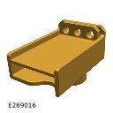
JLR-415-132
Universal Cable Lock-off
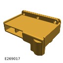
JLR-415-133
12 Volt Battery Lock-off
General Equipment
| Equipment name |
|---|
| Padlock |
Disconnection
NOTES:
- This procedure contains some variation in the illustrations depending on the vehicle specification, but the essential information is always correct.
- This procedure contains illustrations showing certain components removed to provide extra clarity.
- This procedure contains illustrations showing the auxiliary battery for right hand drive vehicles, left hand drive auxiliary battery is similar but on the right side of the engine compartment.
The following step(s) applies to:
All vehicles
- Read the battery charging health and safety precautions.Refer to: Health and Safety Precautions (100-00 General Information, Description and Operation).
- Obtain and record the preset radio frequencies.
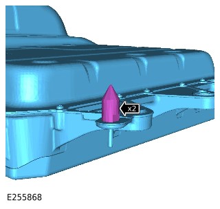
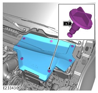
- Remove the 7 fasteners.
- Remove the cowl panel.
The following step(s) applies to:
Plug in hybrid electric vehicles only
- WARNING:
Jaguar Land Rover (JLR) Electric Vehicle Competent Person (EVCP) trained technicians only.
This procedure involves work on components associated with the High Voltage (HV) system. Only technicians qualified to EVCP level or higher are allowed to complete this procedure.
- It is mandated that all technicians involved with the steps in this procedure have read and understood the electric vehicle safety rules.Refer to: Electric Vehicle Safety Rules (414-01B, Description and Operation).
- Remove the engine compartment cross brace.Refer to: Engine Compartment Cross Brace (501-02 Front End Body Panels, Removal and Installation).
- Remove the nut.
- Release the battery negative cable from the Battery Monitoring Sensor (BMS).
The following step(s) applies to:
All vehicles
- Disconnect the electrical connector from the BMS sensor.
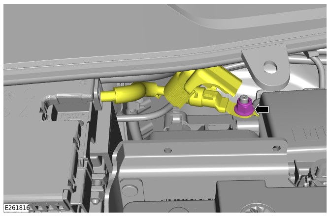
- Loosen the nut.
- Disconnect the startup battery negative terminal.
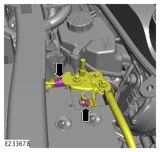
The following step(s) applies to:
Plug in hybrid electric vehicles only
- WARNING:
The key must be placed in the designated key box and secured by the responsible EVCP.
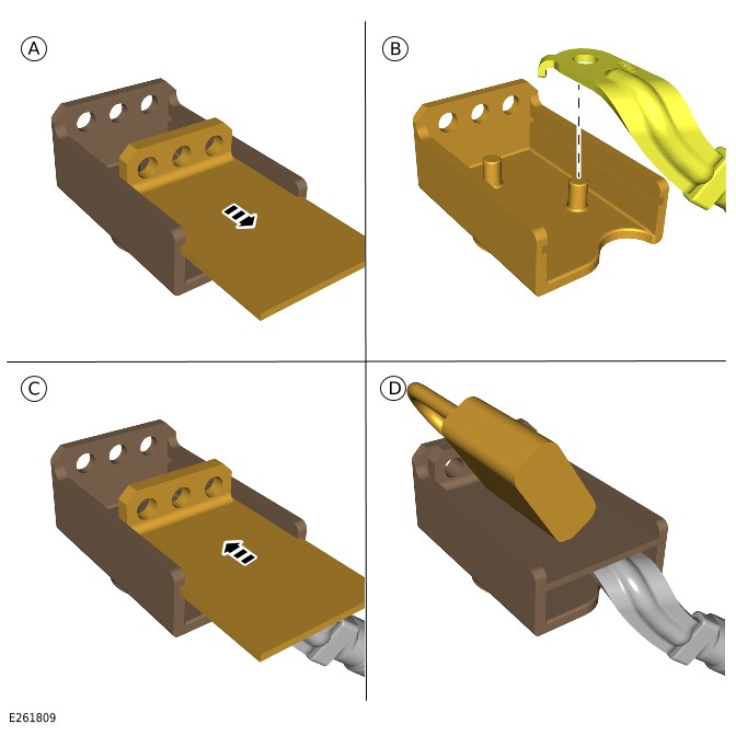
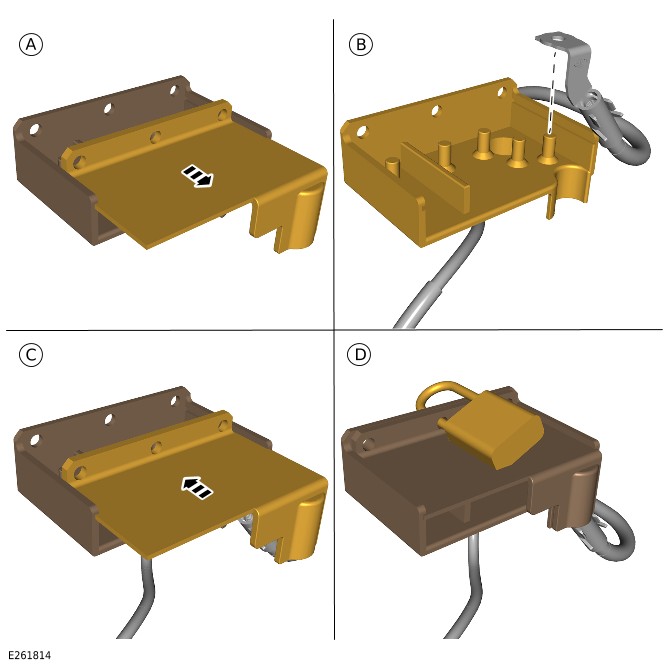
- Remove the lock-off tool lid.Special Tool(s): JLR-415-132
- Secure the battery negative cable in the lock-off tool.
- Install the lock-off tool lid.
- Install the padlock.General Equipment: Padlock
Position the lock-off tool over the battery negative terminal.
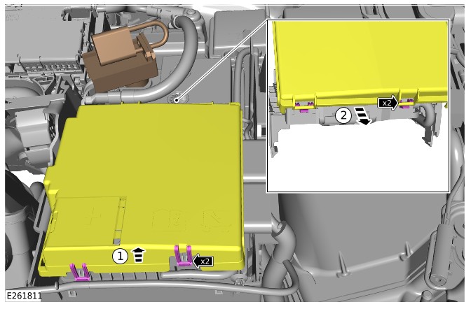
- Release the 2 clips.
- Remove the Battery Junction Box (BJB) lid.
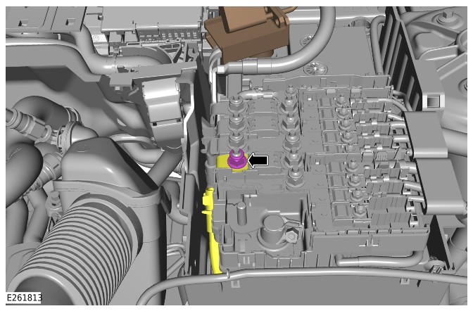
- Remove the nut.
- Release the Direct Current to Direct Current converter (DC/DC) cable from the BJB.
- WARNING:
The key must be placed in the designated key box and secured by the responsible EVCP.
- Remove the lock-off tool lid.Special Tool(s): JLR-415-133
- Secure the DC/DC cable in the lock-off tool.
- Install the lock-off tool lid.
- Install the padlock.General Equipment: Padlock
Disconnect the electrical connector from the auxiliary battery.
- Remove the nut.
- Release the cable from the power supply distribution box.
- WARNING:
The cable must be placed in the designated key box and secured by the responsible EVCP.
- Remove the auxiliary battery cable.
- Place the auxiliary battery cable in the designated key box and lock securely.
- Remove the nut.
- Release the auxiliary battery negative cable.
- WARNING:
The cable must be placed in the designated key box and secured by the responsible EVCP.
- Remove the lock-off tool lid.Special Tool(s): JLR-415-132
- Secure the auxiliary battery negative cable in the lock-off tool.
- Install the lock-off tool lid.
- Install the padlock.General Equipment: Padlock
Connect
The following step(s) applies to:
Plug in hybrid electric vehicles only
- Remove the auxiliary battery negative cable from the lock-off tool.
- Install the auxiliary battery negative cable.
- Install and tighten the nut.Torque: 18Nm
- Install the auxiliary battery cable.
- Install the cable to the power supply distribution box.
- Install and tighten the nut.Torque: 18Nm
- Connect the electrical connector to the auxiliary battery.
- Remove the DC/DC cable from the lock-off tool.
- Install the DC/DC cable.
- Install and tighten the nut.Torque: 18Nm
- Install the BJB lid.
The following step(s) applies to:
All vehicles
- CAUTION:
Make sure the BMS electrical connector is connected to the BMS control module, before installing the BMS onto the battery terminal.
- Connect the electrical connector to the BMS sensor.
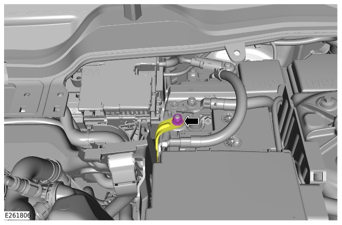
- Connect the startup battery negative terminal as illustrated.
- Tighten the nut.Torque: 6Nm
The following step(s) applies to:
Plug in hybrid electric vehicles only
The following step(s) applies to:
All vehicles
- Install the cowl panel.
- Install the 7 fasteners.
- Complete the door window motor initialization procedure.
- Enter the preset radio frequencies.
- Reset the clock to the correct time.
- Start the engine and allow to idle until the engine reaches normal operating temperature.
- Switch the engine off.
Battery and Charging System - General Information
Battery Charge Procedure (G4345396)
GENERAL PROCEDURES
- 86.15.92
- Startup / Auxiliary Battery - Lead Acid - Increase State of Charge (SoC)
- All Derivatives
- 0.10
- USED WITHINS
Activation
WARNING:
- Do not smoke or carry lighted tobacco or open flame of any type when working on or near the vehicles battery. Highly flammable vapours may be present and ignite. Failure to follow these instructions may result in personal injury.
- Make sure that the battery is well ventilated while the 12V battery conditioner is connected.
- Switch off the current from the 12V battery conditioner before making any electrical connections or disconnections.
- Always follow the safety warnings and operational instructions of the 12V battery conditioner that is being used.
- The positive and negative terminals and connections must not touch each other. Failure to follow this instruction may result personal injury or damage to the vehicle.
CAUTION:
Do not use this procedure where an electric vehicle power down has taken place. Refer to the Electric Vehicle (EV) Safety Rules or an Electric Vehicle Authorized Person (EVAP) for further guidance.
NOTES:
- This procedure contains some variation in the illustrations depending on the vehicle specification, but the essential information is always correct.
- It is recommended that the battery is above 85% State Of Charge (SOC) before returning to the customer.
- NOTE:
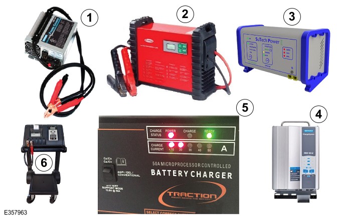
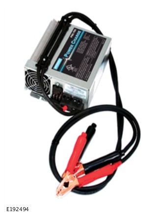
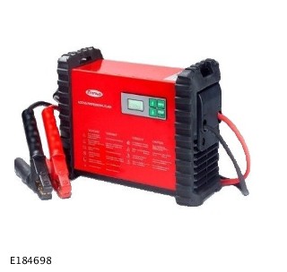
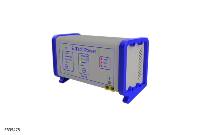
For the Absorbent Glass Mat (AGM)/Lead Acid startup battery charging process one of the following battery conditioners MUST be used:
- Midtronics PSC 700S
- Fronius ACCTIVA Professional Flash
- SuTech SPIC50
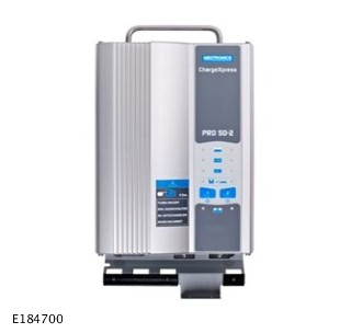
- Midtronics CX-Pro 50
- Traction MPL-50
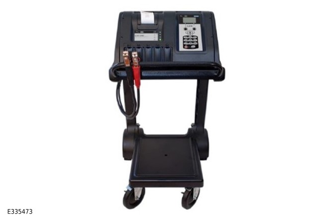
- Midtronics GRX-3080
- Before connecting a 12V battery conditioner technicians involved must read the Battery Care Requirements.Refer to: Battery Care Requirements (414-00 Battery and Charging System - General Information, Description and Operation).
- NOTE:
This step contains connection instructions for the following vehicles:
- E-PACE / X540
- LV / L538
- LC / L550
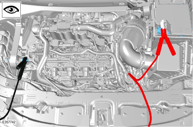
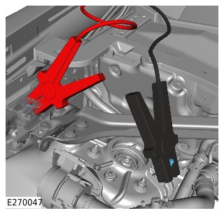
- Connect the battery conditioning unit positive cable to the startup battery positive terminal.
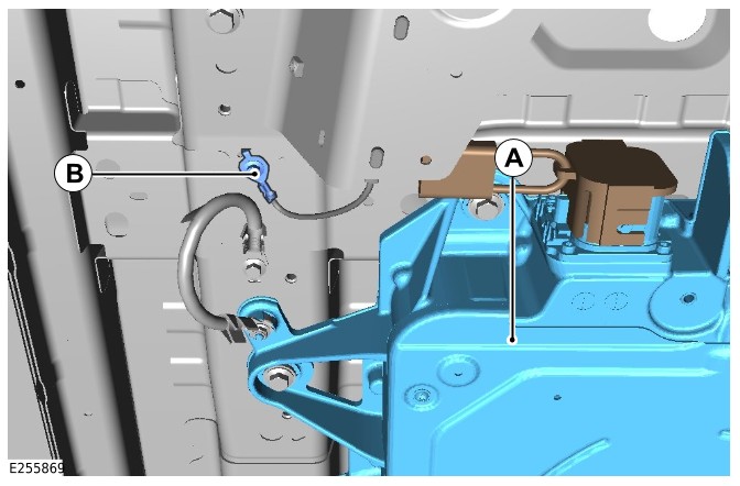
- Connect the battery conditioning unit ground cable to the ground point as illustrated.
- NOTE:
This step contains connection instructions for the following vehicles:
- LZ / L551
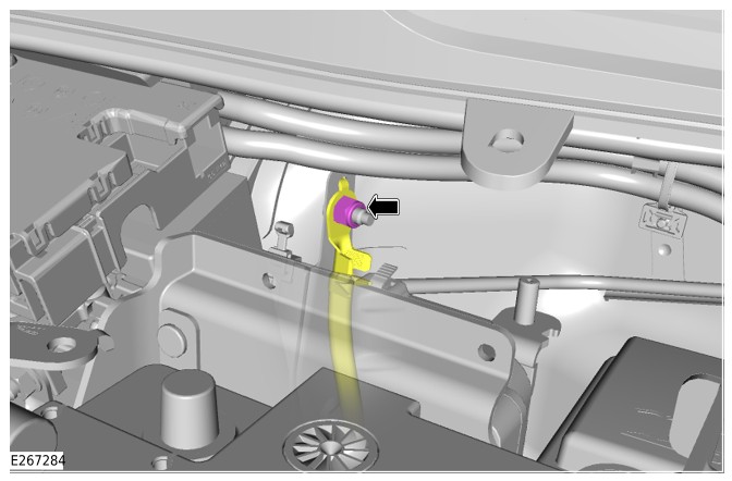
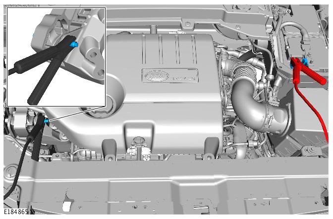
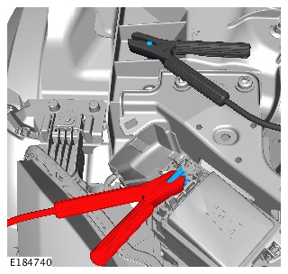
- Connect the battery conditioning unit positive cable to the startup battery positive terminal.
- Connect the battery conditioning unit ground cable to the ground point as illustrated.
- NOTE:
This step contains connection instructions for the following vehicles:
- LY / L560
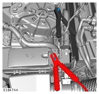
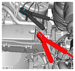
- Connect the battery conditioning unit positive cable to the startup battery positive terminal.
- Connect the battery conditioning unit ground cable to the ground point as illustrated.
- NOTE:
This step contains connection instructions for the following vehicles:
- LG / L405
- LW / L494
- LR / L462
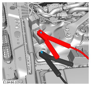
- Connect the battery conditioning unit positive cable to the startup battery positive terminal.
- Connect the battery conditioning unit ground cable to the ground point as illustrated.
- NOTE:
This step contains connection instructions for the following vehicles:
- LE / L663
- Connect the battery conditioning unit positive cable to the startup battery positive terminal.
- Connect the battery conditioning unit ground cable to the ground point as illustrated.
- NOTE:
This step contains connection instructions for the following vehicles:
- F-TYPE / X152
- Connect the battery conditioning unit positive cable to the startup battery positive terminal.
- Connect the battery conditioning unit ground cable to the ground point as illustrated.
- NOTE:
This step contains connection instructions for the following vehicles:
- XE / X760
- XF / X260
- Connect the battery conditioning unit positive cable to the startup battery positive terminal.
- Connect the battery conditioning unit ground cable to the ground point as illustrated.
- NOTE:
This step contains connection instructions for the following vehicles:
- F-PACE / X761
- Connect the battery conditioning unit positive cable to the startup battery positive terminal.
- Connect the battery conditioning unit ground cable to the ground point as illustrated.
- NOTE:
This step contains connection instructions for the following vehicles:
- I-PACE / X590
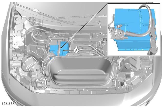
- Disconnect the vehicle from any external High Voltage (HV) power source.
- Remove the front compartment right trim panel.
- Connect the battery conditioning unit to the 12V battery (A).
- CAUTION:
The Midtronics PSC 700S is only to be used in markets with 120V power supply.
NOTE:This step contains operating instructions for the Midtronics PSC 700S battery conditioner.
- Connect the battery conditioning unit to the power supply and switch the battery conditioning unit ON.
- The battery conditioning unit is now charging.
- NOTE:
This step contains operating instructions for the Fronius ACCTIVA Professional Flash battery conditioning unit.
- CAUTION:
The battery conditioning unit must NOT be connected to the vehicle at this stage.
Connect the battery conditioning unit to a power supply.
- NOTE:
The unit will indicate on screen that it is supplying current.
Switch on the battery conditioning unit and using the 'INFO' button select CHARGE mode.
- Set the capacity of the battery using the 'UP' and 'DOWN' arrows.
- Connect the battery conditioning unit positive cable to the startup battery positive terminal.
- Connect the battery conditioning unit ground cable to the ground point.
- The battery conditioning unit is now charging.
- CAUTION:
- CAUTION:
Disconnect the SuTech SPIC50 battery conditioning unit from the supply BEFORE disconnecting it from the battery.
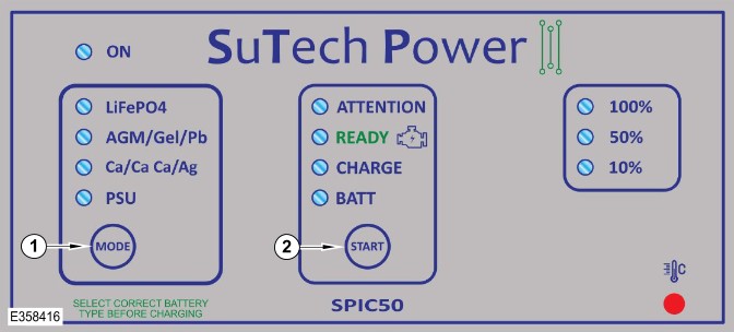
NOTE:The following 2 steps contains operating instructions for the SuTech SPIC50 battery conditioning unit.
- Connect the battery conditioning unit to a power supply.
- Make sure the ON Light Emitting Diode (LED) is illuminated.
- Press 'MODE' button (1) until LiFePO4 indicator is illuminated.
- NOTE:
This step is only applicable if the battery has NOT been removed from the vehicle.
Press the 'START' button (2) until 'CHARGE' LED indicator flashes.
- NOTE:
This step is only applicable if the battery has been removed from the vehicle.
Press and hold the 'START' button (2) until 'CHARGE' LED indicator flashes.
- The battery conditioning unit is now charging.
- NOTE:
The following 2 steps contain operating instructions for the Midtronics CX-Pro 50 battery conditioning unit.
- Connect the vehicle link cable to port 1 on the base of the battery conditioning unit.
- Switch the ignition ON, but do not start the engine.
- The battery conditioning unit is now charging.
- NOTE:
A green light will confirm the battery conditioning unit is switched ON
Switch ON the battery conditioning unit.
- NOTE:
An orange light indicates that power is being supplied to the battery.
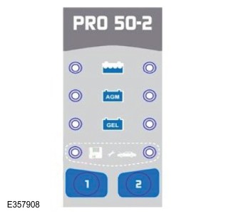
Use button '1' to select the applicable battery type.
- The battery conditioning unit is now charging.
- NOTE:
- NOTE:
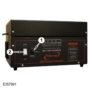
This step contains operating instructions for the Traction MPL-50 battery conditioning unit.
- CAUTION:
The battery conditioning unit must NOT be connected to an power supply at this stage.
Connect the battery conditioning unit positive cable to the startup battery positive terminal.
- Connect the battery conditioning unit ground cable to the ground point.
- Use switch '1' to select the applicable battery type.
- Connect the battery conditioning unit to the power supply and turn it on using switch '2'.
- The battery conditioning unit is now charging.
- CAUTION:
- CAUTION:
You MUST disconnect the battery from the vehicle before charging with the Midtronics GRX-3080.
NOTE:This step contains operating instructions for the Midtronics GRX-3080 battery conditioning unit.
- Connect the battery conditioning unit to the power supply and switch the battery conditioning unit ON.
- Connect the battery conditioning unit positive cable to the battery positive terminal.
- Connect the battery conditioning unit ground cable to the battery negative terminal.
- Highlight DIAGNOSTIC from the menu using the direction arrow keys and press the 'SELECT' button.
- Use the 'UP' or 'DOWN' arrows to select the applicable brand and press 'NEXT'.
- Enter the Vehicle Identification Number (VIN) number and press 'NEXT'.
- Select 'OUT OF VEHICLE' and press 'NEXT'.
- Use the 'UP' or 'DOWN' arrows to select the applicable battery type and press 'NEXT'.
- Use the 'UP' or 'DOWN' arrows to select the applicable battery rating unit and press 'NEXT'.
- Use the 'UP' or 'DOWN' arrows to enter the battery rating in CCA and press 'NEXT'.
- Use the 'UP' or 'DOWN' arrows to enter the battery rating in Ah and press 'NEXT'.
- The battery conditioning unit is now charging.
Battery and Charging System - General Information
Sleep Cycle and Quiescent Drain Configuration (G4586752)
GENERAL PROCEDURES
General Equipment
| Equipment name |
|---|
| Digital Multimeter |
Configuration
CAUTION:
Diagnosis by substitution from a donor vehicle is NOT acceptable. Substitution of control modules does not guarantee confirmation of a fault, and may also cause additional faults in the vehicle being tested and/or the donor vehicle.
NOTE:
If a control module or component is at fault or may be at fault and the vehicle remains under manufacturer warranty, refer to the Warranty Policy and Procedures manual, or determine if any prior approval program is in operation, prior to installation of a new module/component.
- CAUTION:
This step is only applicable on vehicles installed with a secure tracker feature.
NOTE:- The 'Service Mode' feature is not available on North American Specification (NAS) market vehicles.
- Before disconnecting power to the Telematic Control Unit Module (TCU) the vehicle owner must place the TCU into 'Service Mode'. The 'Service Mode' disables all alert triggers, except movement alert.
- This must be done for example when disconnecting the startup battery for maintenance or repairs.
- For security purposes 'Service Mode' is the sole responsibility of the vehicle owner as it requires a Personal Identification Number (PIN) code that has been defined by the owner.
- The TCU 'Service Mode' can be activated in the following ways:
- Through the Call Center - The owner calls the Telematics Service Provider (TSP) and requests to the set the vehicle into 'Service Mode'.
- Through the 'InControl© Remote' mobile phone application - The owner enables the 'Service Mode'.
- Through the InControl© website - The owner enables the 'Service Mode'.
- NOTE:
- If the TCU is not set into 'Service Mode', then communication to and from the TCU may be lost, which may prevent the vehicle starting.
- Failure to do so may result in a warranty claim being rejected.
- 1. The customer through the 'InControl© Remote' mobile phone application.
- 2. The Telematics Service Provider (TSP).
- Then the system will enter 'Theft Notification' or 'Stolen Vehicle Tracking' mode during which time the charge in the TCU battery would be used. The emergency services may be falsely alerted that the vehicle has been stolen.
- When the startup battery is disconnected for a period of time, the vehicle owner can define the time it is to be disconnected for. If the time is exceeded, the vehicle owner must re-activate the 'Service Mode'. To re-activate the 'Service Mode' the vehicle owner is required to use 'InControl© Remote' mobile phone application.
NOTES:
- When performing voltage or resistance tests, always use a digital multimeter accurate to three decimal places, and with an up-to-date calibration certificate. When testing resistance always take the resistance of the digital multimeter leads into account.
- For 21MY onwards vehicles, the internal motions sensors must be turned off before locking the vehicle. The interior motions sensor is an alarm sensor. The alarm sensors can be enabled and disabled, for one alarm cycle only, from the vehicle settings menu. See Owners Hand Book INSTRUMENT PANEL MENU.
- Vehicle shutdown can be monitored by the hazard switch illumination, in correct conditions this will switch off after a period of 30 minutes apart from Plug-in Hybrid Electric Vehicle (PHEV) and Battery Electric Vehicle (BEV) vehicles, this can be up to 60 minutes.
- 1. Refer to the corresponding bulletins and SSMs which may be valid for the specific customer complaint and complete the recommendations as required.
- 2. Visually check for any none-approved accessories installed to the vehicle such as aftermarket instrument panel cameras, towbar/trailer modules, vehicle security immobilizers, infotainment screens and any interior or exterior lighting.
- 3. In the instance that any of these components are present, ask the customer if the fault was only present after these were installed. If this is the case, ask the customer for permission before removing the components from the vehicle circuit and check for vehicle shutdown behavior.
- 4. Remove any potential electrical drains such as accessories plugged into accessory sockets.
- 5. Remove any external charging or support units, both High Voltage (HV) and low voltage.
- 6. Connect the current clamp to the digital multimeter.General Equipment: Digital Multimeter
- 7. Calibrate the current clamp, according to the manufacturers instructions.
- 8. Install the current clamp around the startup battery ground cable.
- 9. Open and latch all doors, hood, tailgate or luggage compartment lid.
- NOTE:
For vehicles with power doors, the doors must be latched fully open. Any movement of the door will cause the latch to open and the vehicle to wake up.
10. Lock the vehicle using the remote function on the smart key (single lock only to avoid volumetric sensor arming, only if the option to turn off volumetric sensors is not available in the instrument cluster).
- 11. Place smart key away from the vehicle (approximately 5 meters) to prevent the Remote Function Actuator (RFA) from preventing the vehicle network shutdown procedure.
- NOTE:
The following step (step 12) is only applicable if the vehicle shutdown behavior is as expected (hazard light switch Light Emitting Diode (LED) extinguishes within the recommended time period).
12. Wait for the vehicle shutdown to complete, if the indicator listed above is not available, wait until the specified time for vehicle shutdown.
- 13. Using the calibrated current clamp, measure and record the amperage reading. The expected quiescent drain value must be below 30mA (average over 10 minutes).
- NOTE:
Vehicles with approach unlocking and walk-away locking can have a quiescent drain of up to 40mA, even when the vehicle is in a sleep condition, as this feature can be active for up to 72hrs.
14. Using the calibrated current clamp, measure the amperage reading of the individual leads at the battery junction box to identify the circuit in which the excessive current consumption is present.
- 15. Continuing with this method, follow the current consumption along the circuit to focus and identify on the root cause component.
Battery, Mounting and Cables - PHEV (G2408924)
SPECIFICATIONS
General Specification - Stop-start and timed climate models
| Item | Specification |
|---|---|
| Battery: | |
| Type | H7 Absorbent Glass Mat (AGM) (VRLA) |
| Capacity | 80Ah/800CCA |
General Specification - Stop-start and timed climate models
| Item | Specification |
|---|---|
| Secondary Battery: | |
| Type | AGM |
| Capacity | 14Ah/200CCA |
General Specification - Non stop-start and timed climate models
| Item | Specification |
|---|---|
| Battery: | |
| Type | H7 Flooded |
| Capacity | 80Ah/700CCA |
General Specification - Plug-in Hybrid Electric Vehicle (PHEV) models
| Item | Specification |
|---|---|
| Battery: | |
| Type | CATL |
| Number of Modules | 7 |
| Capacity | 51Ah |
| Power | 2.215kWh |
| Nominal Voltage | 43.44 |
General Specification - PHEV models
| Item | Specification |
|---|---|
| Battery: | |
| Type | SDI |
| Number of Modules | 7 |
| Capacity | 49.5Ah |
| Power | 2.14kWh |
| Nominal Voltage | 43.2 |
Startup Battery Terminal Installation
CAUTION:
Make sure the clamping lug on the Battery Monitoring Sensor (BMS) is below the top of the negative terminal post as shown.
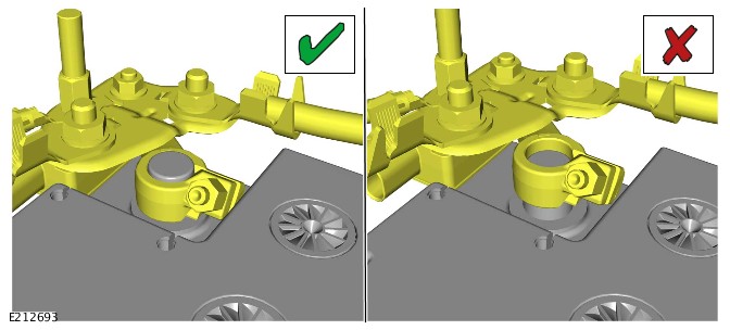
|
Torque Specifications
| Component Torque Location |
|---|
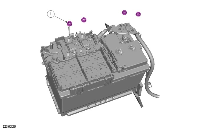
|
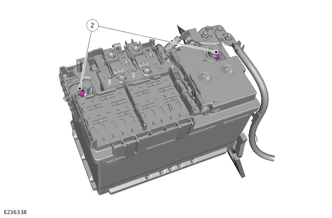
|
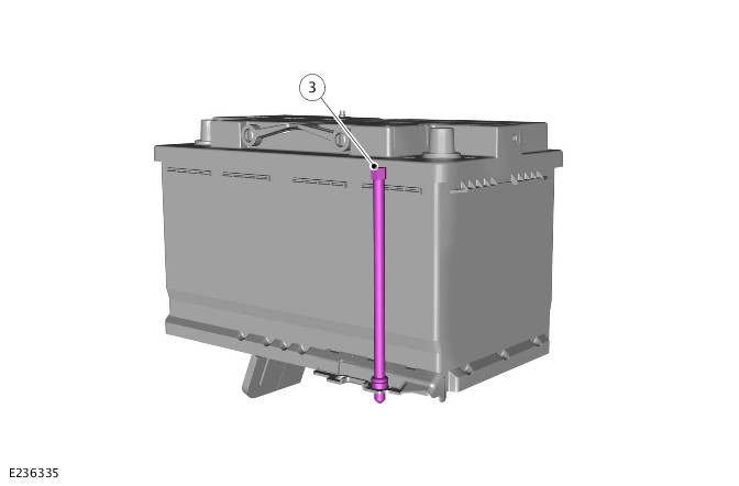
|
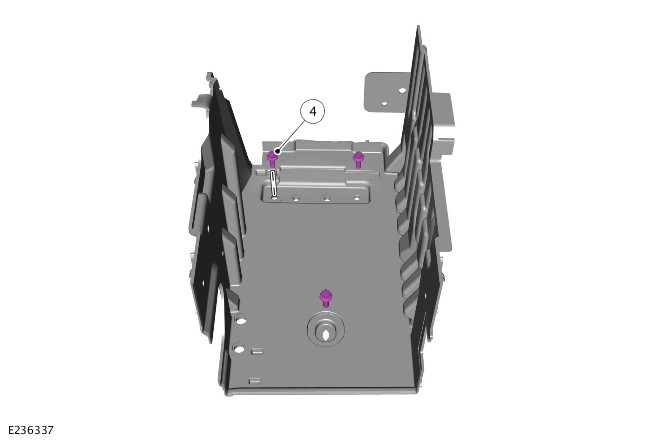
|
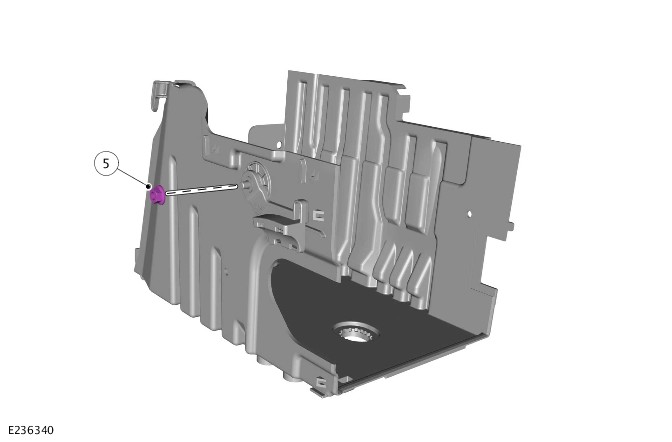
|
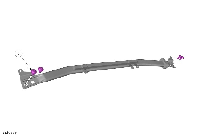
|
| Description | Nm | lb-ft | |
|---|---|---|---|
| 1 | Startup battery cable nuts | 18 | 13 |
| 2 | Startup battery terminal nuts | 6 | 4 |
| 3 | Startup battery retainer | 24 | 17 |
| 4 | Startup battery tray bolts | 10 | 7 |
| 5 | Wiring harness nut | 10 | 7 |
| 6 | Cross brace bolts | 25 | 18 |
Torque Specifications - PHEV
| Component Torque Location |
|---|
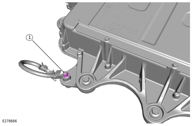
|
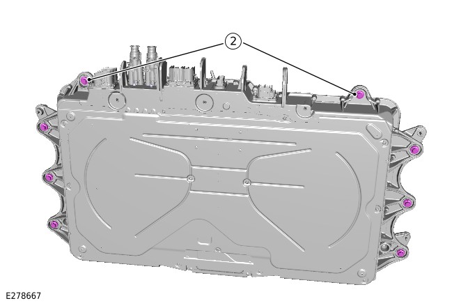
|
| Description | Nm | lb-ft | |
|---|---|---|---|
| 1 | Ground cable nut | 4.8 | 3.5 |
| 2 | Battery retaining bolts | 60 | 44 |
Battery, Mounting and Cables - PHEV
Startup Battery and Cables (G2408925)
DESCRIPTION AND OPERATION
COMPONENT LOCATION
COMPONENT LOCATION - 1 of 1 - LOW VOLTAGE SYSTEM
NOTE:
Right Hand Drive (RHD) vehicle is shown, Left Hand Drive (LHD) vehicle is similar.
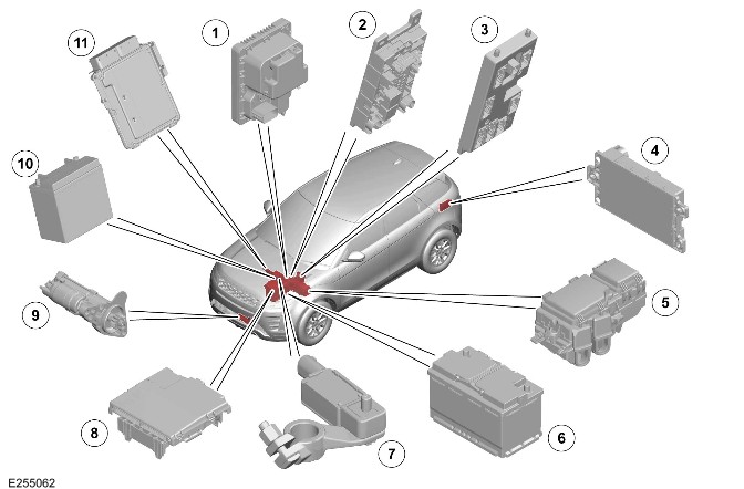
| Item | Description |
|---|---|
| 1 | Power Supply Distribution Box (PSDB) |
| 2 | Passenger Junction Box (PJB) |
| 3 | Body Control Module (BCM)/Gateway Control Module (GWM) |
| 4 | Rear Junction Box (BCMB) |
| 5 | Engine Junction Box (EJB) |
| 6 | Startup battery |
| 7 | Battery Monitoring System (BMS) control module |
| 8 | Battery Junction Box (BJB) |
| 9 | Start motor |
| 10 | Auxiliary battery |
| 11 | Powertrain Control Module (PCM) |
OVERVIEW
12V Dual Battery System
During all modes of operation the 12V power network is supported by the Direct Current to Direct Current converter (DC/DC). The DC/DC is powered from the High Voltage (HV) power network and steps down the voltage from 350V to 12V. While in Power Mode 7 (Vehicle Ready) both the startup and auxiliary battery are in circuit and are charged by the DC/DC.
The startup battery provides power to the BJB.
The BJB contains 3 megafuses, delivering power to the:
- Tandem Solenoid Starter (TSS) motor
- High Voltage Junction Box (HVJB)
- PSDB.
The Electric Vehicle (EV) mode system is disabled if:
- The dual battery system is unable to prevent electrical supplies to the vehicle systems being subjected to low voltage levels during engine EV operations.
- If the condition of the startup and/or auxiliary batteries are inadequate.
- If a system fault exists.
The dual battery system comprises the following components:
- BJB
- PSDB
- Startup battery
- Auxiliary battery.
The BCM/GWM contains the software required to control the dual battery system and components. The BCM/GWM monitors the components and can store fault related Diagnostic Trouble Code(s) (DTC)s.
The BCM/GWM determines if the 12V power supply system can support the EV mode.
The BCM/GWM sends appropriate signals to the PCM through the FlexRay to inhibit EV mode if the following occurs:
- If faults are detected in the BMS control module or PSDB.
- If the battery condition is poor.
- If the battery State of Charge drops below a threshold.
- If the battery temperature is below a threshold.
The BCM/GWM contains the Intelligent Power Management System (IPMS). The BMS software is contained within the BMS control module and communicates with the IPMS through Local Interconnect Network (LIN). The IPMS uses information from the BMS and PSDB in order to determine the condition of both batteries.
The positive jump start terminal is located on the BJB. A cover protects the positive terminal when not in use. If jump starting is required, the cover must be removed and the positive jump lead attached securely. The cover must be equipped to the positive terminal when not in use. The negative jump lead is on the battery negative post.
TRANSIT MODE
All new vehicles are delivered from the factory in transit mode. Transit mode replaces the traditional transit relay, inhibits a number of electrical systems and features to eliminate quiescent drain from the startup battery during delivery. Transit mode inhibits EV mode.
To remove the vehicle from transit mode, the Jaguar Land Rover (JLR) approved diagnostic equipment must be connected during the Pre-Delivery Inspection (PDI).
For additional information, refer to: Preliminary (101-01 Pre-Delivery Inspection Manual, Description and Operation).
Power Modes
The BCM/GWM controls the power supplies for the various vehicle functions. There are 9 Power Modes available to determine the operating condition of the vehicle.
Only 5 of these modes are noticeable to the driver and technicians as follows:
- Power Mode 0
- Vehicle locked and security system armed. EV battery can be charged.
- Power Mode 4
- Accessory (vehicle unlocked and Smart Key present).
- Power Mode 6
- Ignition ON - foot is not on the brake pedal.
- Power Mode 7
- ‘Vehicle Ready’ (foot was on the brake pedal) (‘Ready’ displayed on Instrument Panel Cluster (IPC)), engaging DRIVE or REVERSE on the Transmission Control Switch (TCS) starts motion. The systems transition through Power Mode 9 to get from Power Mode 6 to Power Mode 7.
- Power Mode 9
- Goes through this mode when going from Power Mode 6 to Power Mode 7.
DESCRIPTION
STARTUP battery, Auxiliary battery AND BATTERY MONITORING SYSTEM CONTROL MODULE
CAUTION:
- When connecting a slave power to the vehicle, never connect directly to the startup battery negative terminal, because the BMS control module can be damaged.
- Due to the self-calibration routine, it is recommended that all power supply diagnostic and testing are done using the JLR approved diagnostic equipment.
NOTE:
- RHD vehicle is shown, LHD vehicle is similar.
- The auxiliary battery is not installed with a BMS control module.
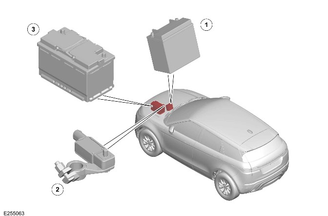
| Item | Description |
|---|---|
| 1 | Auxiliary battery |
| 2 | BMS |
| 3 | Startup battery |
The startup battery is located on a plastic tray in the engine compartment in a left position in front of the PSDB and covered by BJB.
An auxiliary battery is located in the rear center of the engine compartment on a battery support tray. The auxiliary battery negative terminal is connected through a cable to the vehicle body. A cable connects the positive terminal with the PSDB.
Both of the batteries are vented through a tube. Both of the batteries are installed with a strap, threaded rods and a clamp bolted to a tray.
The startup battery is a H7 80Ahr, 850 Cold Cranking Amps (CCA) Absorbed Glass Mat (AGM) Valve Regulated Lead-Acid (VRLA) battery on all vehicles.
The auxiliary battery is a B19 14Ahr, 200 CCA AGM battery on all Plug-in Hybrid Electric Vehicle (PHEV)s.
The startup battery negative terminal is installed with a BMS control module. The BMS control module is integral with the startup battery negative cable and is controlled by the BCM/GWM.
The BMS control module is connected into the vehicle wiring harness through a multiplug. The BMS control module receives a 12V power supply directly from the startup battery positive terminal. The BMS control module measures battery current, voltage and temperature. The BMS control module sends the measured values to the BCM/GWM. A LIN connection provides the communication between the BCM/GWM and the BMS control module. The BCM/GWM controls and monitors the startup battery current drain and State of Charge.
Failure to use the recommended ground point leads to the setting of a DTC. Incorrect information of startup battery condition is retained by the BMS control module due to the unmonitored current flow into the startup battery. The system however, recognizes and compensates for the change in startup battery status after a period of time.
If a new startup battery is installed, the BMS control module requires re-calibration using a JLR approved diagnostic equipment. Replacement of the BMS control module requires no action as the control module re-calibrates automatically.
The BCM/GWM requests an output from the DC/DC through the PCM.
The BMS control module DTCs can be used to help diagnose BMS faults. The DTCs are stored in the BCM/GWM. These DTCs can be read using the JLR approved diagnostic equipment. The JLR approved diagnostic equipment has a process for an automated power supply diagnostic procedure. The procedure provides a menu driven process to locate a fault in a logical sequence. The procedure uses the capability of the BMS control module LIN controlled functions. Thereby the procedure provides current flow information and detects if the BMS control module is functioning incorrectly.
BCM/GWM
NOTE:
RHD vehicle is shown, LHD vehicle is similar.
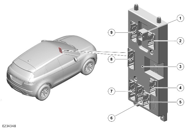
| Item | Description |
|---|---|
| 1 | Main wiring harness connector |
| 2 | Main wiring harness connector |
| 3 | BCM/GWM |
| 4 | Main wiring harness connector |
| 5 | Instrument panel wiring harness connector |
| 6 | Instrument panel wiring harness connector |
| 7 | Main wiring harness connector |
| 8 | Main wiring harness connector |
| 9 | Main wiring harness connector |
The BCM/GWM is attached to a bracket, which is bolted to the passenger side of the instrument panel cross-car beam.
The BCM/GWM is located adjacent to the PJB, and it is the main controller of the vehicle body systems.
The BCM/GWM contains software to control the following functions:
- Determine the condition of the startup and the auxiliary batteries.
- Control the output from the DC/DC.
- The goal is to reach a desired system voltage or target battery State of Charge.
- Load management
- The BCM/GWM monitors the vehicle electrical loads.
- The load management system deactivates loads if the DC/DC is overloaded or the 12V battery is in a degraded condition.
- Control the PSDB to enable the switching of the battery inputs.
- Control the EV system.
- The BCM/GWM can only inhibit EV functionality depending on power system condition.
- The BCM/GWM also provides supporting functionality and PSDB control.
The BCM/GWM communicates with other system control modules on the followings:
- High Speed (HS) Controller Area Network (CAN) power mode zero systems bus.
- HS CAN powertrain systems bus.
- HS CAN chassis systems bus.
- HS CAN comfort systems bus.
- FlexRay.
The BCM/GWM communicates with the BMS control module and the PSDB through a LIN .
POWER SUPPLY DISTRIBUTION BOX
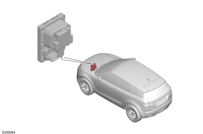
The PSDB is located in the left of the engine compartment, rearward of the startup battery. The PSDB incorporates 2 banks of Metal Oxide Semi-conductor Field Effect Transistors (MOSFET).
The MOSFETs are activated by the BCM/GWM:
- To switch the vehicle loads between the batteries during an EV event.
- For charging the auxiliary battery.
The PSDB receives a battery supply from the startup battery to 'BAT1' terminal through a 300 A megafuse which is located in the BJB. The PSDB receives a battery supply directly from the auxiliary battery to 'BAT2' terminal through a 125 A megafuse.
The PSDB also incorporates a microcontroller, which receives commands from the BCM/GWM through a LIN connection. The PSDB connects or disconnects either the startup or auxiliary battery to the vehicle loads according to the BCM/GWM commands. In addition, there is a diagnostic connection between the BCM/GWM and PSDB, to detect faults of the PSDB.
During each drive cycle the PSDB runs a diagnostics routine to determine the status of the switches. The PSDB reports any faults through the LIN to the BCM/GWM.
STARTUP BATTERY CABLES
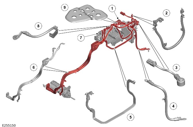
| Item | Description |
|---|---|
| 1 | Negative - Jump start terminal |
| 2 | Wiring harness - Auxiliary battery negative cable |
| 3 | Wiring harness - Auxiliary battery to PSDB positive |
| 4 | Wiring harness - Startup battery negative cable |
| 5 | PHEV Busbar |
| 6 | Wiring harness - Battery cable assembly |
| 7 | Positive - Jump start terminal |
| 8 | Wiring harness - BJB to PSDB |
| 9 | BMS ground plate |
OPERATION
Battery Charging
The startup battery State of Charge is monitored by the BCM/GWM with the BMS control module. In Power Mode 7 (Vehicle Ready) the startup battery State of Charge is maintained by the BCM/GWM with the DC/DC.
BATTERY MONITORING SYSTEM CONTROL MODULE
When in Power Mode 0 (Vehicle locked and security system armed), the EV battery can be charged. The BMS control module records the startup battery State of Charge and battery condition.
If the battery State of Charge falls by 7%, the BMS control module monitors the startup battery for 5 minutes. After the 5 minute monitoring period, if the startup battery charge has continued to fall the BMS control module determines some control modules are still 'awake'. The BMS control module sends a 'shutdown' message on the LIN to the BCM/GWM. The BCM/GWM then transmits a 'Shut down' message on the CAN system buses to all control modules, requesting them to shut down.
The BMS control module monitors the startup battery State of Charge for a further 5 minutes, to determine if the State of Charge is still dropping. If a quiescent drain current continues, the startup battery State of Charge continues to drop. If the State of Charge falls to 12% of the initial monitoring value, the BMS control module determines 1 or more control modules are still awake. The failure to respond to the shutdown request may indicate an error state within the control module(s).
The BMS control module sends a 'power disconnect' signal to the BCM/GWM on the LIN. The BCM/GWM then sends a signal to the BCMB to open its internal relays. When the relays are open, the power supply from the startup battery to non-critical control modules is removed. The non-critical control modules are any modules associated with the infotainment system and also the climate control system.
The use of a LIN communication provides that no other control modules are 'woken' during this process. If CAN bus communication was used, all modules on the CAN bus would be woken by the message.
If a low voltage condition is detected the BMS control module can request the infotainment system is switched OFF to protect startup battery voltage.
BATTERY MONITORING SYSTEM CONTROL MODULE LOW BATTERY WARNING AND ENERGY MANAGEMENT MESSAGES
The BMS control module continuously monitors the condition of the startup vehicle battery. If excessive battery discharge occurs, the system begins to shut down non-essential electrical systems in order to protect the battery.
The BMS control module displays warning messages to inform the driver:
- The startup battery is either at a low level of charge.
- The engine off power consumption limit has been exceeded.
There are 3 messages that can be displayed, 2 on the Interactive Control Display Module (ICDM) and 1 on the message center:
Low Battery - Please switch engine on or system will shutdown in 3 minutes
This message is displayed as a 'Warning' on the ICDM when in Power Mode 6 (Ignition ON - foot is not on the brake pedal). This indicates that the startup battery has fallen below a predefined threshold. As soon as the startup battery is charged above this threshold then the message is removed.
Low Battery - Please start your engine
This message is displayed on the message center in Power Mode 7 (Vehicle ready) or lower. This indicates that the startup battery has fallen below a predefined threshold. As soon as the battery is charged above this threshold then the message is removed. This message can be manually removed by pressing the 'OK' switch on the left Steering Wheel Switch (SWS).
System will shut down in 3 minutes
This message is displayed as an 'Energy management' message on the ICDM. This message appears if below Power Mode 7 (Vehicle Ready), and system features are causing excessive startup battery discharge. After 3 minutes the BCM/GWM begins shutting down vehicle systems. Normal system operation resumes when in Power Mode 9 (Goes through this mode when going from Power Mode 6 to Power Mode 7).
These messages are based on a percentage of battery capacity available for the user to use the vehicle systems in Power Mode 4 ( Accessory). The percentage can change based upon several factors.
When activated, the resetting of these messages does not occur until the vehicle is driven for 10 minutes in Power Mode 7 (Vehicle Ready). This time allows the battery to replace any lost charge. However, if the engine is run for less than 10 minutes, the messages only are displayed after an additional 5 minutes. This occurs when in Power Mode 6 (Ignition ON - foot is not on the brake pedal).
DUAL BATTERY SYSTEM
The dual battery system prevents:
- Electrical loads on the vehicle being subjected to low voltage levels.
- In Power Mode 9 (Goes through this mode when going from Power Mode 6 to Power Mode 7).
Low voltage can occur due to the power demand of the TSS motor and could result in degraded performance of components. The BCM/GWM contains the software to control the dual battery system. The BCM/GWM contains the electrical load management system to provide that EV mode does not affect other vehicle systems.
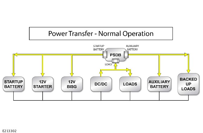
When in Power Mode 7 (Vehicle Ready), the electrical systems are powered from the startup and auxiliary battery through the PSDB. The BCM/GWM and the PSDB communicate through the LIN . The PSDB controls the contactors to isolate the auxiliary battery from the system by opening its contactor.
Normal State
When in Power Mode 7 (Vehicle Ready), the electrical systems are powered from the startup and auxiliary battery through the PSDB. The BCM/GWM and the PSDB communicate through the LIN . The PSDB controls the contactors to isolate the auxiliary battery from the system by opening its contactor.
The BCM/GWM monitors the State of Charge of both the startup and auxiliary batteries. Thereby the BCM/GWM provides that sufficient voltage is available for the EV mode. The BCM/GWM can apply charging to the auxiliary battery through the PSDB if required.
Normal Operation
Electric Vehicle Mode
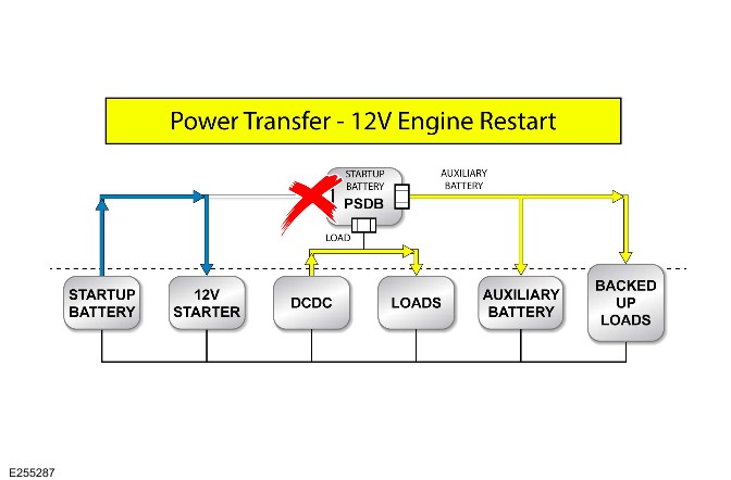
The Belt Integrated Starter Generator (BISG) will be used to restart the engine for EV mode to engine running transitions. When the BISG or HV system is not capable of supporting the engine restart:
- The 12V starter motor is used.
- The PSDB switches.
Diagnostics
The BCM/GWM records any DTCs and related data. Read the DTCs and related data with the JLR approved diagnostic equipment.
The JLR approved diagnostic equipment enables certain components to be activated and also live data to be read.
CONTROL DIAGRAM
CONTROL DIAGRAM - 1 of 1
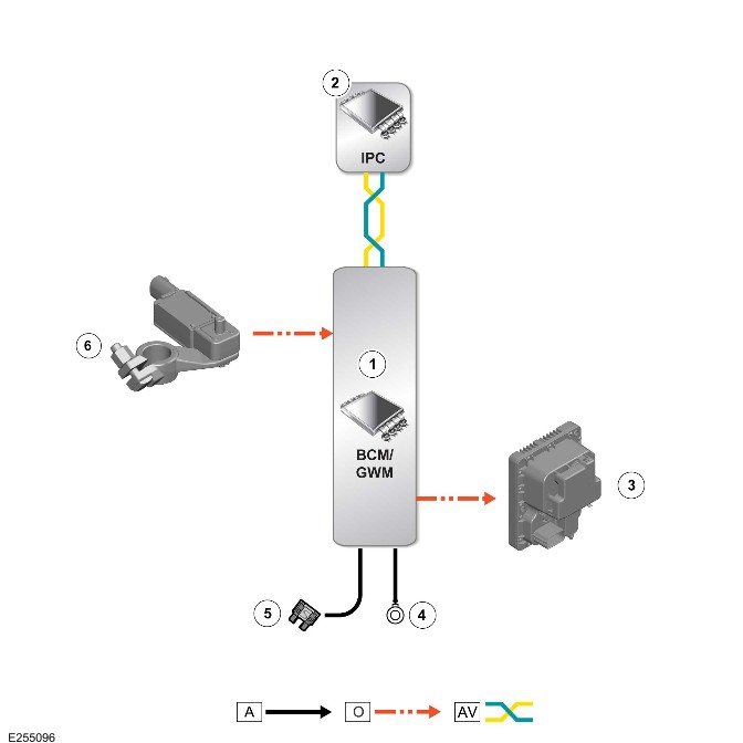
A = Hardwired: O = LIN : AV = HS CAN COMFORT SYSTEM BUS.
| Item | Description |
|---|---|
| 1 | BCM/GWM |
| 2 | IPC |
| 3 | PSDB |
| 4 | Ground |
| 5 | Power supply |
| 6 | BMS control module |
PHEV Battery and Cables (G2408926)
DESCRIPTION AND OPERATION
Component Location
WARNING:
Do not do any work on the High Voltage (HV) electric system until the HV system on the vehicle is powered down.
Component Location - 1 of 2 - Components
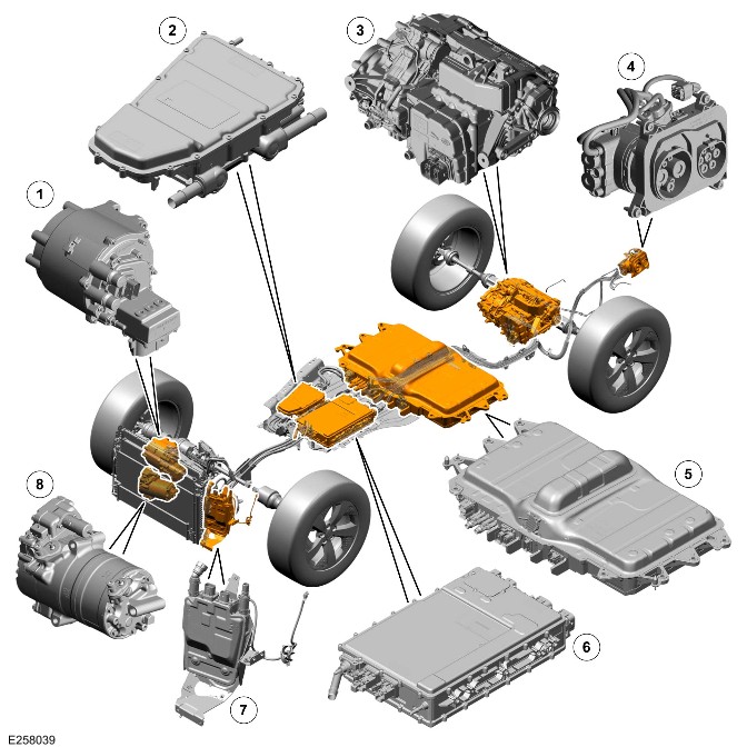
| Item | Description |
|---|---|
| 1 | Belt Integrated Starter Generator (BISG) |
| 2 | BISG inverter/Electric Power Inverter Converter Control Module 'B' (EPICB) |
| 3 | Electric Rear Axle Drive (eRAD) |
| 4 | Charging socket |
| 5 | Plug-in Hybrid Electric Vehicle (PHEV) battery |
| 6 | High Voltage Integrated Box |
| 7 | HV interior heater |
| 8 | HV Alternating Current (AC) Air Conditioning (A/C) compressor |
Component Location - 2 of 2 - High Voltage Wiring Harnesses
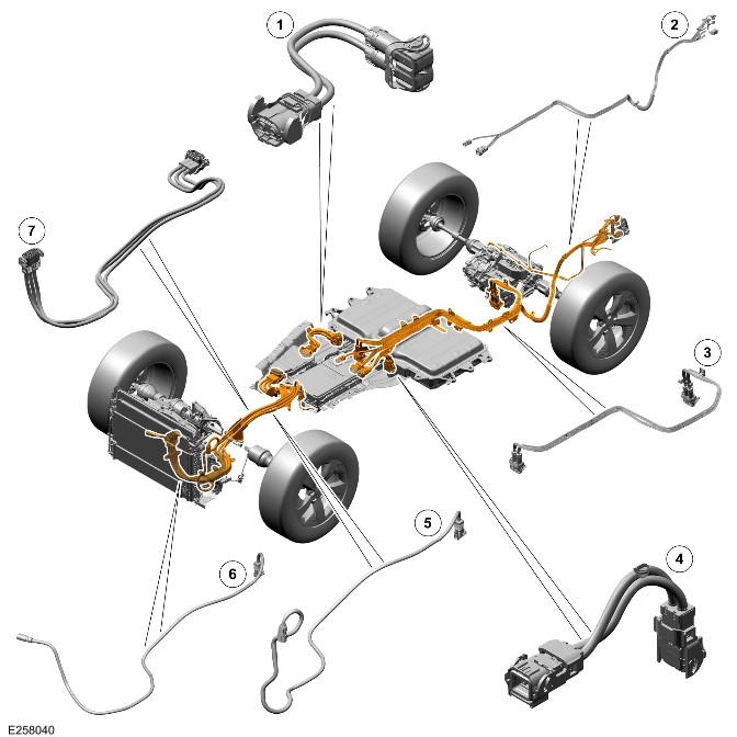
| Item | Description |
|---|---|
| 1 | HV harness from the HV BISG to the PHEV battery |
| 2 | HV harness from the charging port to the High Voltage Integrated Box |
| 3 | HV harness from the PHEV battery to the eRAD inverter |
| 4 | HV harness from the PHEV battery to the High Voltage Integrated Box |
| 5 | HV harness from the High Voltage Integrated Box to the HV interior heater |
| 6 | HV harness from the High Voltage Integrated Box to the HV electric AC A/C compressor |
| 7 | HV harness from the HV BISG to the HV BISG/EPICB |
Overview
WARNING:
Do not do any work on the HV electric system until the HV system on the vehicle is powered down.
The PHEV battery and HV cables provide the HV Direct Current (DC) electrical supply for the vehicle. The PHEV battery stores the electrical energy provided from the external voltage supply from the battery onboard charger or from the eRAD when regenerative braking. The PHEV battery also stores the electrical energy from the HV BISG when it is operating as a generator. The stored HV electrical energy in the PHEV battery is used by the following components:
- The eRAD controlled by the eRAD inverter.
- For additional information, refer to: Electric Rear Axle Drive (205-02B Rear Drive Axle/Differential - PHEV, Description and Operation).
- The Direct Current to Direct Current (DC/DC).
- For additional information, refer to: HV Integrated Box (414-03 Battery Charging, Description and Operation).
- The electric HV AC A/C compressor.
- For additional information, refer to: (412-01 Climate Control)Air Conditioning - Vehicles With: PHEV (Description and Operation), Control Components (Description and Operation).
- The HV interior heater.
- For additional information, refer to: (412-01 Climate Control)Heating and Ventilation (Description and Operation), Control Components (Description and Operation).
- The HV BISG for starting, battery charging and torque fill.
- For additional information, refer to:Starting System (303-06C Starting System - INGENIUM I3 1.5L Petrol, Vehicles With: MHEV, Description and Operation), Belt Integrated Starter Generator - Vehicles With: PHEV (414-03 Battery Charging, Description and Operation), Inverter - Vehicles With: PHEV (414-03 Battery Charging, Description and Operation).
Description
Plug-in Hybrid Electric Vehicle battery
WARNING:
Do not do any work on the PHEV battery until the HV system on the vehicle is powered down.
For additional information, refer to: PHEV Power Down/Up – Complete Vehicle (414-01C Battery, Mounting and Cables - PHEV, General Procedures).
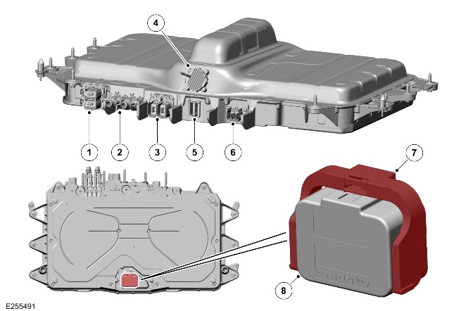
| Item | Description |
|---|---|
| 1 | HV connector to the BISG inverter/EPICB |
| 2 | PHEV battery temperature control coolant connections |
| 3 | HV DC connections to the eRAD |
| 4 | Breather connection |
| 5 | Vehicle wiring harness connection |
| 6 | HV DC connection from the High Voltage Integrated Box |
| 7 | Master Service Disconnect (MSD) locking lever |
| 8 | MSD |
The PHEV battery is made of a number lithium ion cells that are connected together in modules. These modules are then connected together to form the PHEV battery.
The PHEV battery has an MSD.
The PHEV battery has these electrical connections:
- The HV connection to High Voltage Integrated Box.
- The HV connection to the eRAD inverter.
- The HV connection to the HV BISG inverter./EPICB
- The vehicle wiring harness.
For additional information, refer to: HV Integrated Box (414-03 Battery Charging, Description and Operation).
Plug-in Hybrid Electric Vehicle battery Manual Service Disconnect
WARNING:
Do not do any work on the PHEV battery until the HV system on the vehicle is powered down.
The MSD is located under the PHEV battery. The MSD disconnects the electrical circuit within the PHEV battery.
The MSD has a lock to secure it to the MSD connection. The MSD lock lever must be moved before the MSD can be removed from the MSD connection.
After re-installing the MSD make sure that the MSD lock lever is fully closed before operating the vehicle. Use a Jaguar Land Rover (JLR) approved diagnostic equipment to make sure that no Diagnostic Trouble Codes (DTC) have been stored for the PHEV battery.
Battery Energy Control Module
The Battery Energy Control Module (BECM) is an integral part of the PHEV battery. The BECM controls the individual battery cell voltages, internal temperatures and the HV relays.
The BECM communicates with the HV system and other vehicle systems through the High Speed (HS) Controller Area Network (CAN) power mode zero systems bus.
The PHEV battery has a BECM to control the internal temperature of the PHEV battery. The BECM has a number of temperature sensors positioned in the PHEV battery. The BECM uses the temperature sensors to control the internal temperature of the PHEV battery within a specified temperature range. The BECM controls:
- A PHEV battery coolant pump.
- A PHEV battery heater.
- A PHEV battery cooler connected to the A/C system.
- A PHEV battery changeover valve.
The PHEV battery temperature control system uses coolant to heat and cool the inside of the PHEV battery. The coolant is circulated through the system by a PHEV battery coolant pump, controlled by the BECM. The BECM uses a Pulse Width Modulated (PWM) to control the speed of the PHEV battery coolant pump.
The heat for the PHEV battery temperature control system is provided by the PHEV battery heater in the temperature control system. This increases the temperature of the coolant to increase the internal temperature of the PHEV battery, when the internal PHEV battery temperature is below a set temperature.
The cooling for the PHEV battery is from 2 sources. The BECM uses the appropriate cooling source depending on the internal temperature of the PHEV battery. The 2 sources are:
- The PHEV battery coolant radiator
- The PHEV battery coolant cooler.
For additional information, refer to: PHEV Battery Temperature Control (414-01C Battery, Mounting and Cables - PHEV, Description and Operation).
The BECM monitors the individual PHEV battery cell voltages when the vehicle is in operation or the PHEV battery is charging. The BECM compares the PHEV battery cell voltages and adjusts them based on a delta voltage difference. If the vehicle is not to be used for an extended period of time, connect to an external power supply to maintain the PHEV battery condition. This will maintain the PHEV battery state of charge at a high level.
For additional information, refer to: HV Integrated Box (414-03 Battery Charging, Description and Operation).
The BECM also monitors the HV interlock loop for any breaks.
High Voltage Harness From the Plug-in Hybrid Electric Vehicle battery to the High Voltage Integrated Box
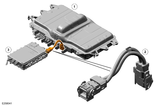
| Item | Description |
|---|---|
| 1 | PHEV battery |
| 2 | HV harness |
| 3 | High Voltage Integrated Box |
The HV harness between the PHEV battery and the High Voltage Integrated Box has 2 cables. The harness is a HV DC harness.
The connectors at each end have 2 HV connections and 2 HV interlock loop connectors.
The harness is used when the vehicle is being charged from an external charging source. The harness is also used when the DC/DC is converting the HV DC stored in the PHEV battery to 12V for use by the vehicle systems.
High Voltage Harness from the High Voltage Integrated Box to the High Voltage Interior Heater
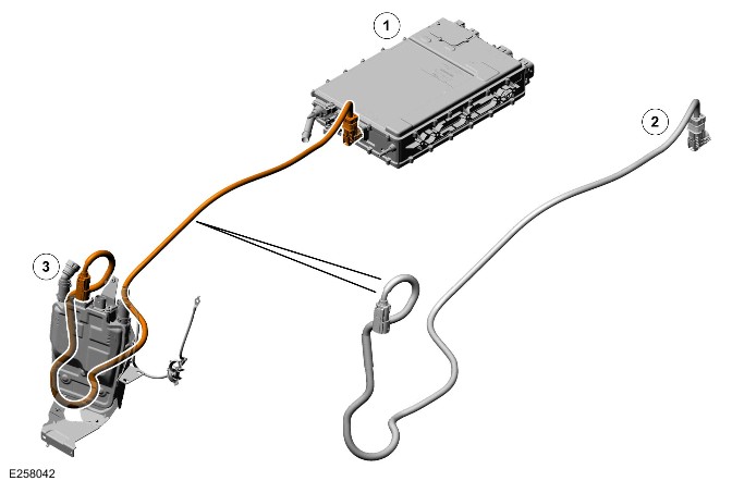
| Item | Description |
|---|---|
| 1 | PHEV battery |
| 2 | HV harness |
| 3 | HV interior heater |
The HV harness between the HV interior heater and the High Voltage Integrated Box has 2 cables. The harness is a HV DC harness. There is a fuse in the High Voltage Integrated Box in the heater supply line.
The connectors at each end have 2 HV connections and 2 HV interlock loop connectors.
The control of the HV interior heater is by the HVAC Control Module (HVAC) control module.
For additional information, refer to: Control Components (412-01 Climate Control, Description and Operation).
High Voltage Harness from the High Voltage Integrated Box to the High Voltage Alternating Current Air Conditioning Compressor
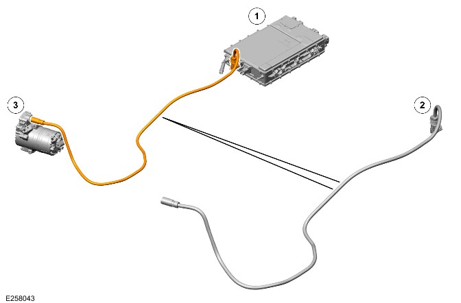
| Item | Description |
|---|---|
| 1 | High Voltage Integrated Box |
| 2 | HV harness |
| 3 | HV AC A/C compressor |
The HV harness between the HV AC A/C compressor and the High Voltage Integrated Box has 2 cables. The harness is a HV DC harness. There is a fuse in the High Voltage Integrated Box in the HV AC A/C compressor supply line.
The connectors at each end have 2 HV connections and 2 HV interlock loop connectors.
The control of the HV AC A/C compressor is by the HVAC control module.
For additional information, refer to: Control Components (412-01 Climate Control, Description and Operation).
High Voltage Harness from the High Voltage Belt Integrated Starter Generator to the High Voltage Belt Integrated Starter Generator inverter (EPICB)
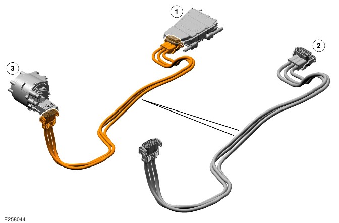
| Item | Description |
|---|---|
| 1 | BISG inverter (also known as EPICB) |
| 2 | HV harness |
| 3 | HV BISG |
The HV harness between the HV BISG and the BISG inverter/EPICB has 3 cables. The harness is a HV AC harness.
The connectors at each end have 3 HV connections and 2 HV interlock loop connectors.
The harness has a HV supply if the HV BISG is operating as a generator. It will also have a supply if the HV BISG is operating as a motor. The HV BISG operates as a starter during stop/start operations or as a motor for torque fill operation. The operation of the HV BISG and the BISG inverter, also known as EPICB is controlled by the Vehicle Supervisory Controller (VSC) which is in the Powertrain Control Module (PCM).
High Voltage Harness from the Belt Integrated Starter Generator inverter(EPICB) to the Plug-in Hybrid Electric Vehicle battery
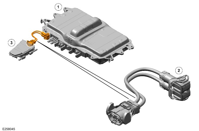
| Item | Description |
|---|---|
| 1 | PHEV battery |
| 2 | HV harness |
| 3 | The HV BISG inverter/EPICB |
The HV harness between the HV BISG inverter/EPICB and the PHEV battery has 2 cables. The harness is a HV DC harness.
The connectors at each end have 2 HV connections and 2 HV interlock loop connectors.
The harness has a HV supply if the BISG is operating as a generator or a motor. The operation of the BISG inverter/EPICB is controlled by the VSC which is in the PCM.
High Voltage Harness from the Plug-in Hybrid Electric Vehicle battery to the electric Rear Axle Drive inverter(EPICB)
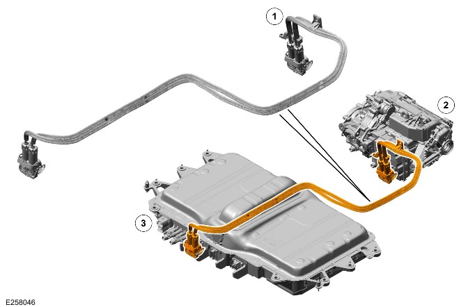
| Item | Description |
|---|---|
| 1 | HV harness |
| 2 | eRAD and eRAD inverter |
| 3 | PHEV battery |
The HV harness between the eRAD inverter(EPICB) and the PHEV battery has 2 cables. The harness is a HV DC harness.
The connectors at each end have 2 HV connections and 2 HV interlock loop connectors.
The harness has a supply if the eRAD is operating as a motor or as a generator during regenerative braking. The operation of the eRAD is controlled by the VSC which is in the PCM.
High Voltage Harness from the Charge connector to the High Voltage Integrated Box
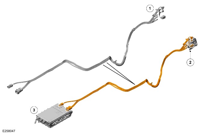
| Item | Description |
|---|---|
| 1 | HV harness |
| 2 | Charging socket |
| 3 | High Voltage Integrated Box |
Depending on the market and specification of the vehicle, the harness from the charge connector to the High Voltage Integrated Box will be a HV AC cable and/or a HV DC cable.
The AC charging connector at the High Voltage Integrated Box end has 2 HV AC connections and 2 HV interlock loop connectors. The DC charging connector at the High Voltage Integrated Box end has 2 HV DC connections and 2 HV interlock loop connectors.
Electrical Bonding
All the electrical components of the HV system have an electrical bonding connection to the vehicle chassis. This makes sure that there are no electrical shocks due to voltage differences between the HV components and the metal chassis components. The HV components with individual electrical bonding are:
- PHEV battery
- eRAD
- High Voltage Integrated Box
- HV BISG inverter/EPICB
- HV interior heater.
The HV AC A/C compressor uses the engine and transmission ground cables.
Operation
WARNING:
Do not do any work on the HV electric system until the HV system on the vehicle is powered down.
The PHEV battery stores the electrical energy from the following:
- The onboard charger
- For additional information, refer to: HV Integrated Box (414-03 Battery Charging, Description and Operation).
- The eRAD when regenerative braking, controlled by the VSC in the PCM.
- The BISG inverter(also known as EPICB) when the HV BISG is operating as a generator.
The PHEV battery delivers electrical energy to the following:
- The eRAD controlled by the eRAD inverter.
- For additional information, refer to: Electric Rear Axle Drive (205-02B Rear Drive Axle/Differential - PHEV, Description and Operation).
- The HV BISG when operating as a starter motor or a motor for toque fill.
- The HV interior heater
- For additional information, refer to: (412-01 Climate Control)Heating and Ventilation (Description and Operation), Control Components (Description and Operation).
- The HV AC A/C compressor
- For additional information, refer to: (412-01 Climate Control)Air Conditioning - Vehicles With: PHEV (Description and Operation), Control Components (Description and Operation).
- The vehicle 12V electrical systems through the DC/DC in the High Voltage Integrated Box.
- For additional information, refer to: HV Integrated Box (414-03 Battery Charging, Description and Operation).
The BECM controls the HV energy both delivered and supplied by the PHEV battery. The BECM may restrict the amount of energy delivered or supplied if the PHEV battery internal temperature is outside the normal operational temperature range.
The BECM also controls the temperature of the PHEV battery. The PHEV battery temperature control operates when the vehicle is driven. The PHEV battery temperature control also operates while the PHEV battery onboard charger is connected to an external power supply by the charging port.
For additional information, refer to: PHEV Battery Temperature Control (414-01C Battery, Mounting and Cables - PHEV, Description and Operation).
High Voltage Interlock Loop
The HV interlock loops are controlled by the BECM. The HV interlock loops has a current sensor that is monitored by the BECM for the disconnection of a HV cable connector. The HV interlock loop has a 12V 10mA electric circuit that loops through the HV connectors of the following components:
- MSD
- BISG
- Electric AC A/C compressor
- PHEV battery
- BECM (internal to the PHEV battery)
- High Voltage Integrated Box (the DC/DC and the onboard charging module are part of this unit)
- BISG inverter/EPICB
- HV coolant heater.
The HV interlock loop for the eRAD inverter is a separate system. The status of the HV connector is reported over the CAN system.
When a HV cable on any of the above is removed the HV interlock loop circuit is broken and the BECM detects the break. The BECM sends the HV interlock loop status to the PCM. If the vehicle is stationary the PCM requests the BECM to break the HV circuit. The BECM de-energizes 2 relays inside the PHEV battery to electrically disconnect the PHEV battery and the HV circuits discharge.
Control Diagram
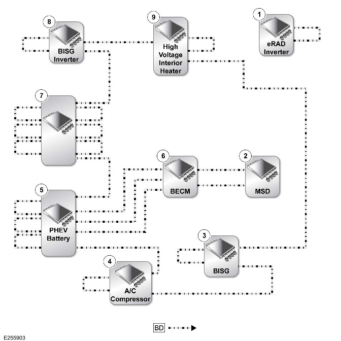
BD = High Voltage Interlock Loop.
| Item | Description |
|---|---|
| 1 | eRAD inverter |
| 2 | MSD |
| 3 | HV BISG |
| 4 | HV AC A/C compressor |
| 5 | PHEV battery |
| 6 | BECM (internal to the PHEV battery) |
| 7 | High Voltage Integrated Box |
| 8 | HV BISG inverter/EPICB |
| 9 | HV interior heater |
PHEV Battery Temperature Control (G2431238)
DESCRIPTION AND OPERATION
COMPONENT LOCATION
WARNING:
Do not do any work on the High Voltage (HV) electric system until the HV system on the vehicle is powered down.
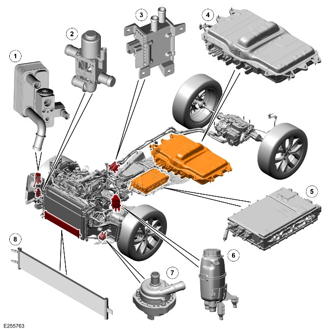
| Item | Description |
|---|---|
| 1 | Plug-in Hybrid Electric Vehicle (PHEV) battery coolant cooler |
| 2 | PHEV battery coolant changeover valve |
| 3 | PHEV battery coolant heater |
| 4 | PHEV battery |
| 5 | High Voltage Integrated Box |
| 6 | PHEV battery coolant expansion tank |
| 7 | PHEV battery coolant pump |
| 8 | PHEV battery coolant radiator |
OVERVIEW
WARNING:
Do not do any work on the HV electric system until the HV system on the vehicle is powered down.
The PHEV battery temperature control system provides both cooling and heating for the PHEV battery. The cooling prevents the PHEV battery from overheating. The heating enables the PHEV battery to get to an optimum operating temperature quickly. The cooling enables the PHEV battery to deliver the required power under most conditions. The Battery Energy Control Module (BECM) uses temperature data from sensors positioned inside the PHEV battery. The BECM is part of the PHEV battery.
The temperature sensors used to monitor the internal temperature of the PHEV battery are of the Negative Temperature Coefficient (NTC) resistors type. The data from the temperature sensors is used by the BECM to regulate the internal temperature of the PHEV battery. If the PHEV battery internal temperature exceeds specified limits the BECM will decrease the power available from the PHEV battery.
The PHEV battery temperature control system consists of the following components:
- PHEV battery coolant pump
- PHEV battery expansion tank
- PHEV battery radiator
- PHEV battery coolant heater
- PHEV battery coolant cooler
- PHEV battery coolant changeover valve
- PHEV battery coolant
- High Voltage Integrated Box
- Pipes and hoses.
DESCRIPTION
Plug-in Hybrid Electric Vehicle Battery
WARNING:
Do not do any work on the PHEV battery until the HV system on the vehicle is powered down.
Plug-in Hybrid Electric Vehicle Battery - Rest of the World
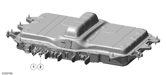
| Item | Description |
|---|---|
| 1 | PHEV battery coolant inlet |
| 2 | PHEV battery coolant outlet |
Plug-in Hybrid Electric Vehicle Battery - China Market
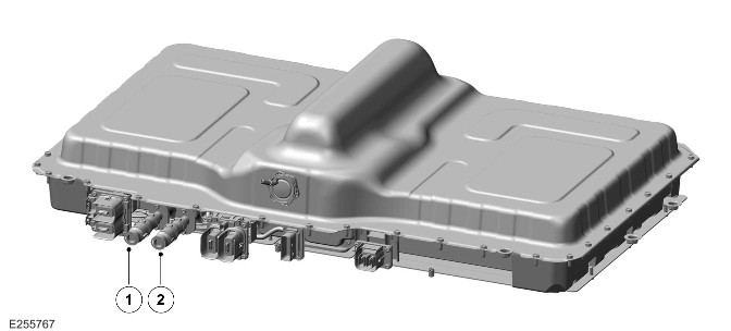
| Item | Description |
|---|---|
| 1 | PHEV battery coolant inlet |
| 2 | PHEV battery coolant outlet |
The PHEV battery is located under the floorpan below the second row seats.
There are 2 types of PHEV battery available for the vehicle, 1 for China only markets and 1 for the Rest of the World (ROW).
The PHEV battery contains the BECM that controls the internal temperature when the vehicle is driven or the PHEV battery is charged.
BECM
The BECM is an integral part of the PHEV battery. The BECM controls the individual battery cell voltages, internal PHEV battery temperatures and the HV relays.
The BECM communicates with the HV system and other vehicle systems through the High Speed (HS) Controller Area Network (CAN) power mode zero systems bus.
The PHEV battery has a temperature control system to maintain the PHEV battery internal temperature within a specific range. The temperature control system uses the PHEV battery coolant to heat and cool the inside of the PHEV battery. The PHEV battery coolant is circulated through the system by a 12V electric pump, controlled by the BECM.
The heat for the PHEV battery temperature control system is provided by external 12V electric heater in the temperature control system. This increases the temperature of the PHEV battery coolant to increase the internal temperature of the PHEV battery. This occurs when the internal PHEV battery temperature is below a set temperature.
The China only battery has a cooling/heating plate inside the battery housing. The ROW battery uses the coolant in channels around the PHEV battery housing.
High Voltage Integrated Box
WARNING:
Do not do any work on the High Voltage Integrated Box until the HV system on the vehicle is powered down.
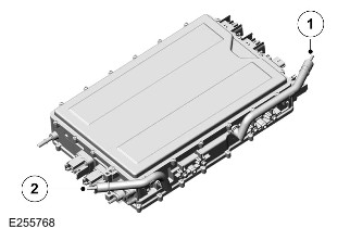
| Item | Description |
|---|---|
| 1 | High Voltage Integrated Box coolant inlet |
| 2 | High Voltage Integrated Box coolant outlet |
The High Voltage Integrated Box is located under the vehicle forward of the PHEV battery
The High Voltage Integrated Box contains the onboard charger and the Direct Current to Direct Current (DC/DC). The High Voltage Integrated Box contains temperature sensors which send the internal temperature to the PHEV battery which controls the PHEV coolant pump.
The temperature sensor data is sent to the PHEV battery on the HS CAN power mode zero systems bus.
For additional information, refer to: HV Integrated Box (414-03 Battery Charging, Description and Operation).
Plug-in Hybrid Electric Vehicle Battery Coolant Pump
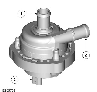
| Item | Description |
|---|---|
| 1 | PHEV battery coolant pump outlet hose connection |
| 2 | PHEV battery coolant pump inlet hose connection |
| 3 | Electrical connection |
The PHEV battery coolant pump is located in the front left of the engine compartment. The PHEV battery coolant pump operation is controlled by the BECM. The PHEV battery coolant pump circulates the PHEV battery coolant through the PHEV battery temperature control system. The speed of circulation of PHEV battery coolant is controlled by a Pulse Width Modulated (PWM) signal from the BECM.
The PHEV battery coolant pump has a 3-pin connector. The 3-pin connector has the following connections:
- A 12V supply from the Engine Junction Box (EJB).
- A PWM signal from the BECM (inside the PHEV battery).
- A ground connection.
Plug-in Hybrid Electric Vehicle Battery Coolant Expansion Tank
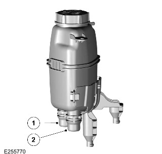
| Item | Description |
|---|---|
| 1 | PHEV battery coolant expansion tank coolant inlet |
| 2 | PHEV battery coolant expansion tank outlet |
The PHEV battery coolant expansion tank is located in the front left of the engine compartment. The PHEV battery coolant expansion tank provides a reservoir of PHEV battery coolant for the PHEV battery temperature control system and also allows the PHEV battery coolant to degas.
The PHEV battery coolant expansion tank has a pressure cap that releases the pressure in the PHEV battery temperature control system if it exceeds a set level.
The PHEV battery coolant expansion tank allows the coolant level to be filled if additional coolant is required.
Plug-in Hybrid Electric Vehicle Battery Coolant Cooler
WARNING:
Do not do any work on the PHEV battery coolant cooler until the HV system on the vehicle is powered down.
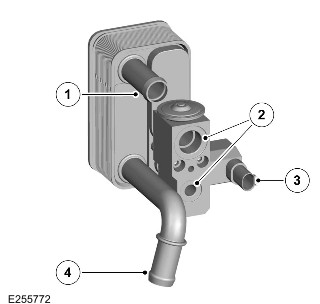
| Item | Description |
|---|---|
| 1 | PHEV battery coolant inlet hose connection |
| 2 | Air Conditioning (A/C) refrigerant connections |
| 3 | Electrical connection |
| 4 | PHEV battery coolant outlet hose connection |
The PHEV battery coolant cooler is located in the front right of the engine compartment. The PHEV battery coolant cooler uses the refrigerant from the A/C to cool the PHEV battery coolant in the PHEV battery temperature control system. The PHEV battery coolant is then circulated through the PHEV battery temperature control system to reduce the internal temperature of the PHEV battery.
The isolation valve that controls the flow of refrigerant though the PHEV battery coolant cooler is controlled by the HVAC Control Module (HVAC) control module. The BECM sends a request to the HVAC control module. The request is sent on the HS CAN power mode zero bus to the HVAC control module. The HVAC control module then activates the following:
- The electric A/C compressor
- The A/C front isolation valve
- The PHEV battery coolant cooler isolation valve.
The refrigerant from the A/C system can then flow through the PHEV battery coolant cooler to cool the PHEV battery coolant.
The PHEV battery coolant cooler has a 2-pin electrical connector on the isolation valve. The 2-pin connector has the following connections:
- A 12V signal from the HVAC control module.
- A ground connection.
For additional information, refer to: (412-01 Climate Control)
Air Conditioning - Vehicles With: PHEV (Description and Operation),
Control Components - [+] InControl Touch Pro (Description and Operation),
Control Components - [+] InControl Touch Pro Duo (Description and Operation).
Plug-in Hybrid Electric Vehicle Battery Radiator
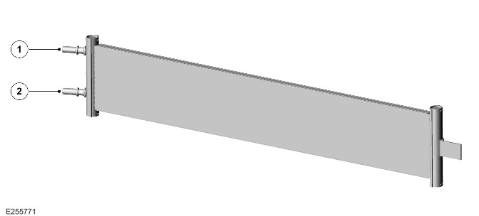
| Item | Description |
|---|---|
| 1 | PHEV battery radiator - Coolant outlet |
| 2 | PHEV battery radiator - Coolant inlet |
The PHEV battery radiator is located in the cooling module at the front of the vehicle. The cooling module uses the vehicle speed and the electric cooling fans to move the air through the cooling pack. The movement of the air cools the PHEV battery coolant in the PHEV battery temperature control system. The flow of PHEV battery coolant through the cooling radiator is controlled by the BECM by:
- A PWM signal to the PHEV battery coolant pump.
- Activate the PHEV battery coolant changeover valve to direct the PHEV battery coolant through the PHEV battery radiator.
Plug-in Hybrid Electric Vehicle Battery Coolant Heater
WARNING:
Do not do any work on the PHEV battery coolant heater until the HV system on the vehicle is powered down.
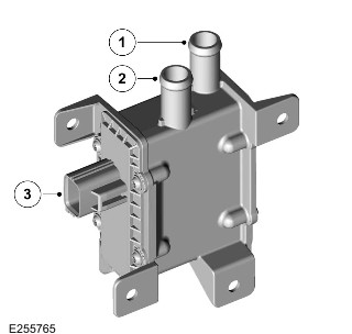
| Item | Description |
|---|---|
| 1 | PHEV battery coolant heater coolant inlet hose connection |
| 2 | PHEV battery coolant heater coolant outlet hose connection |
| 3 | Electrical connection |
The PHEV battery coolant heater is located under the floor on the rear right of the vehicle. The PHEV battery coolant heater provides only a set level of heat input into the PHEV battery coolant. The flow of PHEV battery coolant through the PHEV battery coolant heater is controlled by the BECM by the PHEV battery coolant pump. The PHEV battery coolant heater only operates when the vehicle is plugged into an external charging point.
The PHEV battery coolant heater has a 2-pin connector. The 2-pin connector has the following connections:
- A 12V supply from the Rear Junction Box (RJB) relay, controlled by the BECM.
- A ground connection.
PHEV Battery Coolant Changeover Valve
WARNING:
Do not do any work on the PHEV battery coolant changeover valve until the HV system on the vehicle is powered down.
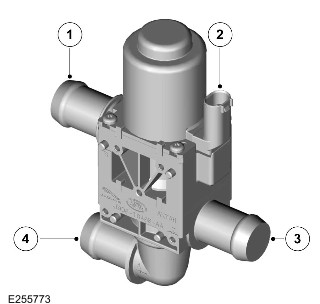
| Item | Description |
|---|---|
| 1 | PHEV battery coolant changeover valve coolant outlet to the PHEV battery coolant cooler |
| 2 | Wiring harness connector |
| 3 | PHEV battery changeover valve coolant inlet |
| 4 | PHEV battery changeover valve coolant outlet to the PHEV battery radiator |
The PHEV battery coolant changeover valve is located in the front right of the engine compartment.
The PHEV battery coolant changeover valve is controlled by the BECM. When the PHEV battery coolant changeover valve solenoid is activated the PHEV battery coolant flows through the PHEV battery coolant cooler. When the PHEV battery coolant changeover valve solenoid is not activated the PHEV battery coolant flows through the PHEV battery radiator.
The PHEV battery coolant changeover valve has a 2-pin electrical connector. The 2-pin connector has the following connections:
- A 12V signal from the BECM.
- A ground connection.
Hoses and Pipes
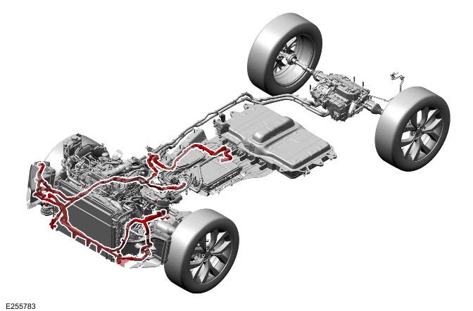
The pipes and hoses connect the various components in the PHEV battery coolant system in series and parallel. This allows the PHEV battery coolant to circulate through the PHEV battery and the PHEV battery temperature control system.
Some of the hoses are covered with a protective sleeve.
OPERATION
WARNING:
Do not do any work on the HV system until the HV system on the vehicle is powered down.
The BECM monitors the internal temperature of the PHEV battery when the vehicle is driven or the PHEV battery is charging.
The PHEV battery coolant heater is only used when the vehicle is connected to an external charging point.
If the internal temperature of the PHEV battery is less than a specified temperature the BECM will activate the PHEV battery coolant pump and the PHEV battery coolant heater. This will heat the PHEV battery coolant and circulate it through the PHEV battery to increase the internal temperature of the PHEV battery.
If the internal temperature of the PHEV battery is more than a specified temperature the BECM will activate the PHEV battery coolant pump and either:
- Activate the PHEV battery coolant changeover valve to allow the PHEV battery coolant to circulate through the PHEV battery radiator.
- Send a message to the HVAC control module to activate the PHEV battery coolant cooler connected to the A/C system. The HVAC control module will then activate the following:
- The electric A/C compressor.
- The A/C front isolation valve. This allows the refrigerant to flow to the PHEV battery coolant cooler.
- The isolation valve on the PHEV battery coolant cooler connected to the A/C system.
The message from the BECM is transmitted to the HVAC control module through the HS CAN power mode zero systems bus.
For additional information, refer to: (412-01 Climate Control)
Air Conditioning - Vehicles With: PHEV (Description and Operation),
Control Components - [+] InControl Touch Pro (Description and Operation),
Control Components - [+] InControl Touch Pro Duo (Description and Operation).
Plug-in Hybrid Electric Vehicle Battery Temperature Control Coolant Flow
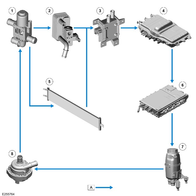
| Item | Description |
|---|---|
| A | Coolant flow |
| 1 | PHEV battery coolant changeover valve |
| 2 | PHEV battery coolant cooler |
| 3 | PHEV battery coolant heater |
| 4 | PHEV battery |
| 5 | Radiator |
| 6 | High Voltage Integrated Box |
| 7 | PHEV battery coolant expansion tank |
| 8 | PHEV battery coolant pump |
CONTROL DIAGRAM
WARNING:
Do not do any work on the HV system until the HV system on the vehicle is powered down.
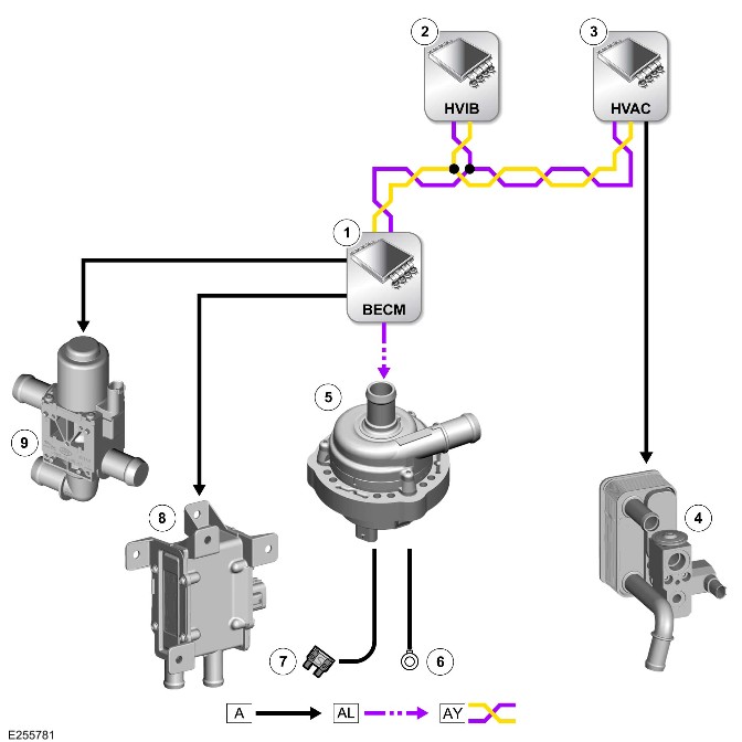
A = Hardwired: AL = PWM: AY = HS CAN power mode zero systems bus.
| Item | Description |
|---|---|
| 1 | BECM (in the PHEV battery) |
| 2 | High Voltage Integrated Box |
| 3 | HVAC control module |
| 4 | PHEV battery coolant cooler |
| 5 | PHEV battery coolant pump |
| 6 | Ground |
| 7 | Power supply |
| 8 | PHEV battery coolant heater |
| 9 | PHEV battery coolant changeover valve |
Hybrid Battery Assessment (G2196323)
DESCRIPTION AND OPERATION
SAFE TRANSPORTATION ASSESSMENT FORM FOR HYBRID BATTERIES
WARNING:
Do not do any work on the high voltage electric system until the high voltage system on the vehicle is powered down.
For additional information, refer to: 12V System Disconnect (414-00 Battery and Charging System - General Information, General Procedures).
WARNINGS:
- This procedure must be performed in the exact sequence shown. Failure to do so could result in serious personal injury.
- This procedure must only be performed by an Electric Vehicle Senior Authorized Person (EVSAP).
- Make sure that you also comply with any local legislation regarding working with high voltages, when performing this procedure.
- Use only approved personal protection equipment, to include: safety glasses or visor, insulated gloves of the required standards and nonflammable, non-melting clothing, must be worn when instructed to do so.
>td rowspan="1">Jaguar Land Rover part number:
| SAFE TRANSPORTATION ANALYSIS SHEET FOR HYBRID BATTERIES |
|---|
| Hybrid battery serial number: |
| Vehicle Identification Number (VIN): |
| Vehicle registration mark: |
| Battery type | Length in CM | Width in CM | Height in CM | Total weight in KG |
|---|---|---|---|---|
| D8 Plug-in Hybrid Electric Vehicle (PHEV) SDI | 129 | 81 | 44 | 147 |
| D7u PHEV | 110 | 85 | 51 | 148 |
| X590 Pack | 242 | 163 | 42 | 750 |
| X590 Electric Vehicle (EV) Battery Module | 45 | 30 | 25 | 13 |
| A123 | 40 | 30 | 40 | 10 |
| EBC21 High Voltage (HV)Battery Pack | 160 | 70 | 28 | 300 |
| EBC 21 Battery Module 8S | 114 | 28 | 26 | 20.4 |
| EBC 21 Battery Module 26S | 149 | 29 | 26 | 48 |
| EVE Mild Hybrid Electric Vehicle (MHEV) | 35 | 17.5 | 17.5 | 12 |
| CATL | 118 | 72 | 34 | 125 |
| STEP 1 | |||
|---|---|---|---|
| Critical safety inspection (Detection of immediate safety concerns): | |||
| Yes | No | ||
| 1 | Are there any active emission of smoke or flames from the hybrid battery? | ||
| Yes | No | ||
| 2 | Are there any active emissions of electric sparks or arcs from the hybrid battery? | ||
| If at least one question is answered Yes, contact the relevant emergency services immediately. | |||
| STEP 2 | |||
|---|---|---|---|
| Inspection for damage: | |||
| Yes | No | ||
| 1 | Are there any indications that an explosion or a fire has taken place? | ||
| Yes | No | ||
| 2 | Are there any indications of loose components within the hybrid battery housing? | ||
| Yes | No | ||
| 3 | Are there any signs that electrolyte has leaked out of the hybrid battery housing? | ||
| Yes | No | ||
| 4 | Are there any cracks or holes in the hybrid battery housing? | ||
| Yes | No | ||
| 5 | Are there any dents or scratches to the hybrid battery housing, that extend beyond what is permitted (depth more than 2.0 mm)? | ||
| Yes | No | ||
| 6 | Are any high voltage connections damaged (normally insulated conductors now exposed)? | ||
| Yes | No | ||
| 7 | With the exception of the hybrid battery temperature control coolant connections, does any coolant leak out of the hybrid battery housing? | ||
| If at least one question is answered Yes, the hybrid battery shall be deemed unsafe for transportation and the vehicle must be quarantined accordingly. Contact Technical Support for further assistance. | |||
>td rowspan="1">Burrs or Edges
| Acceptable Damage Characteristics : | |||
| Characteristic | Baseplate | Frames | Description |
| Split (punctured) | Not acceptable. | Not acceptable. | Failure and localized separation of sheet metal also known as tears or fractures. This defect can occur when metal is worked, thinned or subject to high pressure/deformation, damage. |
| Hole (punctured) | Not acceptable. | Not acceptable. | Holes in the surface penetrating the component. |
| Dents/Dings/Depressions | Less than or equal to a maximum of 2mm deep. The Maximum size is 30X30mm with a maximum of 2 within 200mm of each other. | Less than or equal to a maximum of 2mm deep. The Maximum size is 30X30mm with a maximum of 2 within 200mm of each other. | Flat like bubble depression caused by high pressure/deformation, damage. Slight spot or depressions to the surface, over limited area caused by compression onto the surface. |
| Scratches/Scoring | Less than or equal to 2mm deep. Maximum length 100mm, Maximum width 3mm. Maximum of 2 within 200mm of each other. | Less than or equal to 2mm deep. Maximum length 100mm, Maximum width 3mm. Maximum of 2 within 200mm of each other. | Lines of damage caused by contact and movement across the surface |
| Wrinkles/Deformation/Distortion | Acceptable if part function and operation is not affected. | Acceptable if part function and operation is not affected. | A wavy condition on the metal part due to compressive stresses |
| Corrugations | Acceptable if part function and operation is not affected. | Acceptable if part function and operation is not affected. | Wave like/parallel marks on the surface of a panel at an angle to the direction of rolling or compression which can be seen in a special observed position (for example. looking car forward at a very low angle of observation. |
| Inclusion | Acceptable if part function and operation is not affected. | Acceptable if part function and operation is not affected. | Contamination within the surface such as dirt or partials which protrude or cause irregular in the surface. |
| Streaks/Cloudiness/Fogging/color difference | Acceptable if part function and operation is not affected. | Acceptable if part function and operation is not affected. | Local areas of matt, dull, cloudy or steaks with diffuse transfer between different areas. |
| Surface Corrosion | TBC | TBC | |
| Acceptable if part function and operation is not affected. | Acceptable if part function and operation is not affected. | A thin ridge or roughness left by forgings or sheet metal blanks by cutting operations slitting, shearing, trimming, machining, welding blanking or sawing. | |
| Work marks/scour/polishing streaks | Acceptable if part function and operation is not affected. | Acceptable if part function and operation is not affected. | Directional work marks on the visible surface following the use of hand or rotary operations. |
Startup Battery - RBoM (G2743502)
Part(s)
[EUROPE]
| Name | Mandatory or Optional Part reason | Quantity | Part Number | ||||||||||||||||
|---|---|---|---|---|---|---|---|---|---|---|---|---|---|---|---|---|---|---|---|
| L551 - Startup battery - H6 Battery -12V-70AH, 760A (Main Component) | Optional: Reason Not Set | 1 |
| ||||||||||||||||
| L551 - Startup Battery - H7 Battery - 12V-80AH, 800A, AGM (Main Component) | Optional: Reason Not Set | 1 |
|
Special Tool(s)
Plug in hybrid electric vehicles only
| 12 Volt Battery Lock-offJLR-415-133 | 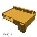 |
| Universal Cable Lock-offJLR-415-132 | 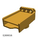 |
Repair
Startup Battery (414-01C REMOVAL AND INSTALLATION G2408934)
Published: 21-Jan-2021
2022.0 New Range Rover Evoque (LZ), 414-01C
Battery, Mounting and Cables - PHEV
Startup Battery (G2408934)
REMOVAL AND INSTALLATION
- 86.15.01
- Startup Battery - Renew
- All Derivatives
- 0.50
- USED WITHINS
Removal
NOTE:
- This procedure contains illustrations showing certain components removed to provide extra clarity.
- This procedure contains some variation in the illustrations depending on the vehicle specification, but the essential information is always correct.
- It is mandated that all technicians involved with the steps in this procedure have read and understood the Electric Vehicle (EV) Safety Rules.Refer to: Electric Vehicle Safety Rules (414-01C Battery, Mounting and Cables - PHEV, Description and Operation).
- WARNING:
Jaguar Land Rover (JLR) Electric Vehicle Competent Person (EVCP) trained technicians only.
- Disconnect the 12V system.Refer to: 12V System Disconnect (414-00 Battery and Charging System - General Information, General Procedures).
- Remove the engine compartment cross brace.Refer to: Engine Compartment Cross Brace (501-02 Front End Body Panels, Removal and Installation).
- Remove the air filter housing.Refer to: Air Filter Housing (303-12C Intake Air Distribution and Filtering - INGENIUM I3 1.5L Petrol, Removal and Installation).
- Release the clip.
- Reposition the vacuum pipe away from the startup battery tray.
- Release the 2 clips.
- Reposition the Mass Air Flow (MAF) sensor wiring harness away from the startup battery tray.
- Release the clip.
- Reposition the transmission breather pipe away from the startup battery tray.
- Remove the startup battery tray upper trim.
- Release the 6 clips.
- Release the 4 clips.
- Remove the startup battery tray front cover.
- NOTE:
Note the installed position of the components prior to removal.
- Remove the 3 nuts.
- Disconnect the 3 cables from the Battery Junction Box (BJB).
- Release the 2 wiring harness grommets.
- Reposition the 2 wiring harnesses away from the startup battery.
- Release the wiring harness clip.
- Disconnect the startup battery positive terminal.
- Release the 4 clips.
- Reposition the BJB away from the startup battery.
- Release the startup battery vent pipe.
- Reposition the start up battery vent pipe away from the startup battery.
Remove the startup battery clamp.
Remove the startup battery assembly.
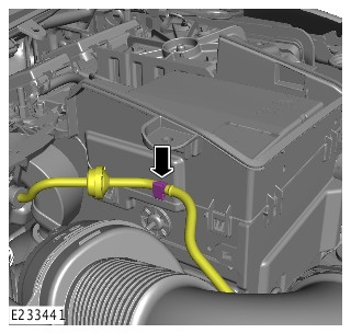
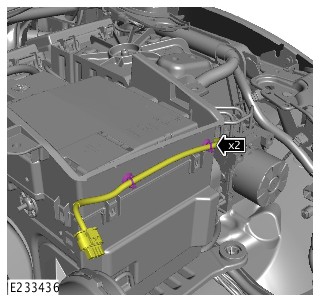
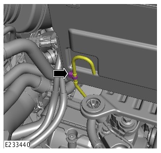
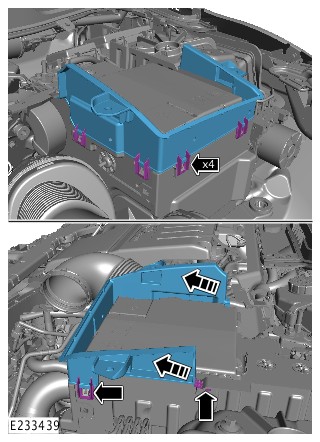
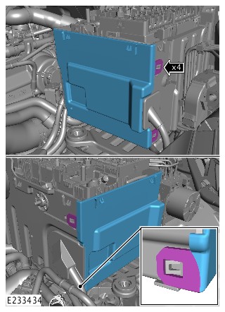
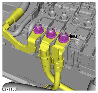
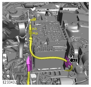
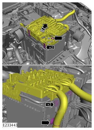
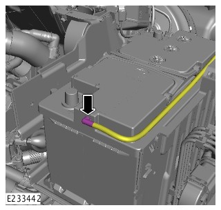
Installation
- Install the startup battery.
- Install and tighten the startup battery clamp.Torque: 24Nm
- Install the startup battery vent pipe.
- Reposition the BJB.
- Install the 4 clips.
- Connect the startup battery positive terminal.
- Make sure the startup battery positive terminal is correctly installed.
- Tighten the nut.Torque: 6Nm
- Install the wiring harness clip.
- Reposition the 2 wiring harnesses into the correct location.
- Install the 2 grommets.
- CAUTION:
Make sure that these components are installed to the noted removal position.
- Connect the 3 cables to the BJB.
- Install and tighten the 3 nuts.Torque: 18Nm
- Install the startup battery tray front cover.
- Install the 4 clips.
- Install the startup battery tray upper trim.
- Install the 6 clips.
- Reposition the transmission breather pipe into the correct location.
- Install the clip.
- Reposition the MAF sensor wiring harness into the correct location.
- Install the 2 clips.
- Reposition the vacuum pipe into the correct location.
- Install the clip.
- Install the air filter housing.Refer to: Air Filter Housing (303-12C Intake Air Distribution and Filtering - INGENIUM I3 1.5L Petrol, Removal and Installation).
- Install the engine compartment cross brace.Refer to: Engine Compartment Cross Brace (501-02 Front End Body Panels, Removal and Installation).
- Connect the 12V system.Refer to: 12V System Disconnect (414-00 Battery and Charging System - General Information, General Procedures).
- CAUTION:
Make sure the Battery Monitoring Sensor (BMS) electrical connector is connected to the module, before installing the BMS on to the battery terminal.
NOTE:This step is only necessary when installing a new battery.
Use Jaguar Land Rover approved diagnostic equipment to reset the BMS.
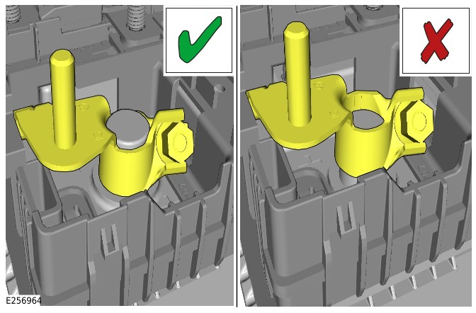
High Voltage Coolant Heater - RBoM (G2929150)
Part(s)
All vehicles
| Name | Quantity | Part Number | ||||
|---|---|---|---|---|---|---|
| HV coolant heater (Main Component) | 1 |
|
Special Tool(s)
All vehicles
| 12 Volt Battery Lock-offJLR-415-133 | |
| Break Out Box - High Voltage (HV) Auxiliary Circuit ConnectorJLR-415-136 | 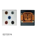 |
| Break Out Box Safety Check Connector – High Voltage (HV) Auxiliary Circuit ConnectorJLR-415-137 | 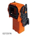 |
| Lock Off - High Voltage (HV) Auxiliary CircuitJLR-415-115 |  |
| Main High Voltage (HV) Connector Lock-offJLR-415-114 | 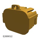 |
| Main High Voltage connector break-out boxJLR-415-134 | 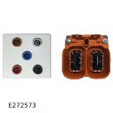 |
| Main High Voltage connector break-out box safety check connectorJLR-415-135 | 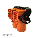 |
| Master Service Disconnect (MSD) Lock-off (CATL Battery)JLR-415-116 |  |
| Master Service Disconnect (MSD) Lock-off (SDI Battery)JLR-415-117 |  |
| Measurement Probes (GS38)JLR-415-092 | 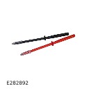 |
| Protective StickerJLR-415-024 |  |
| Universal Cable Lock-offJLR-415-132 | |
| Voltage IndicatorC.A 773 |  |
| Voltage Tester Proving UnitPU690 |  |
| Adaptor, Cooling System Vacuum Refill KitJLR-303-1634 | 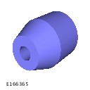 |
| Coolant System Vacuum Refill KitHU-919 | 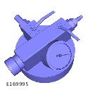 |
Repair
High Voltage Coolant Heater (414-01C REMOVAL AND INSTALLATION G3262201)
Published: 11-Jan-2023
2022.0 New Range Rover Evoque (LZ), 414-01C
Battery, Mounting and Cables - PHEV
High Voltage Coolant Heater (G3262201)
REMOVAL AND INSTALLATION
- 15.10.49
- High Voltage Interior Heater - Renew
- 1500 cc, Ingenium PHEV
- 2.80
- USED WITHINS
General Equipment
| Equipment name |
|---|
| Fluke 1507 Insulation Tester |
Removal
WARNING:
- It is the responsibility of the Electric Vehicle Authorised Person (EVAP) to make sure they comply with any local legislation for work on High Voltage (HV).
- The approved Personal Protective Equipment (PPE) must be worn where indicated within this procedure and not removed unless indicated within a step. All items of PPE must be checked for signs of damage before each use, if damaged, replacement PPE must be obtained before doing this procedure.
- If the vehicle has been powered down, do not power up the vehicle until all the bonding points have been tested.
CAUTION:
- Make sure all the HV connectors, ground points and locating points are clean and free from foreign material before disconnecting and connecting.
- Before disconnecting any components, make sure the area is clean and free from foreign material. When disconnected all openings must be sealed.
NOTE:
- Permit To Work (PTW) documents must be kept for a minimum of 5 years.
- This procedure contains some variation in the illustrations depending on the vehicle specification, but the essential information is always correct.
- This procedure contains illustrations showing certain components removed to provide extra clarity.
- It is mandated that all technicians involved with the steps in this procedure have read and understood the Electric Vehicle (EV) Safety Rules.Refer to: Electric Vehicle Safety Rules (414-01C Battery, Mounting and Cables - PHEV, Description and Operation).
- Before handling any HV connectors the person(s) completing this procedure must refer to the 'High Voltage Electrical Connector Operation and Inspection' document.Refer to: High Voltage Electrical Connector Operation and Inspection (414-01C Battery, Mounting and Cables - PHEV, General Procedures).
- WARNING:
Jaguar Land Rover Jaguar Land Rover (JLR) EVAP trained technicians only.
Power down the HV system. Only technicians qualified to EVAP level or higher are allowed to complete this step of the procedure.Refer to: PHEV Power Down/Up – Complete Vehicle (414-01C Battery, Mounting and Cables - PHEV, General Procedures).
- WARNING:
JLR Electric Vehicle Competent Person (EVCP) trained technicians only.
- Raise and support the vehicle on a suitable 2 post lift.Refer to: Jacking and Lifting (100-02 Jacking and Lifting, Description and Operation).
- Drain the engine and Electric Rear Axle Drive (eRAD) cooling system.Refer to: Engine and eRAD Cooling System Draining and Vacuum filling (303-03C Engine Cooling - INGENIUM I3 1.5L Petrol, General Procedures).
- Remove the engine undershield.Refer to: Engine Undershield (501-02 Front End Body Panels, Removal and Installation).
- Remove the air filter housing.Refer to: Air Filter Housing (303-12C Intake Air Distribution and Filtering - INGENIUM I3 1.5L Petrol, Removal and Installation).
Clamp 2 the coolant hoses to minimize coolant loss.
Disconnect the 2 coolant hoses and reposition them away from the HV coolant heater.
Disconnect the electrical connector.
- Remove the ground cable nut.
- Release the 2 wiring harness clips.
- Disconnect the HV cable connector.
- Remove the nut and bolt.
- Remove the bolt.
- Release the HV cable.
- Remove the 2 nuts and bolts.
- Remove the HV coolant heater.
- NOTE:
Do not disassemble further if the component is removed for access only.
- Remove the 4 bolts.
- Remove the bracket.
- Release the 2 coolant hose clips.
- Remove the 2 coolant hoses.
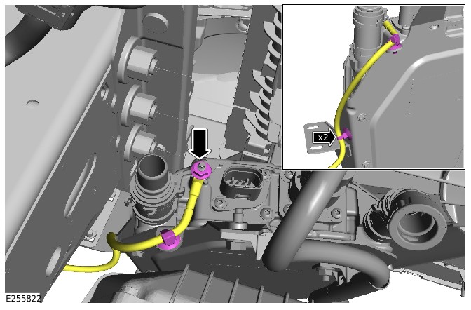
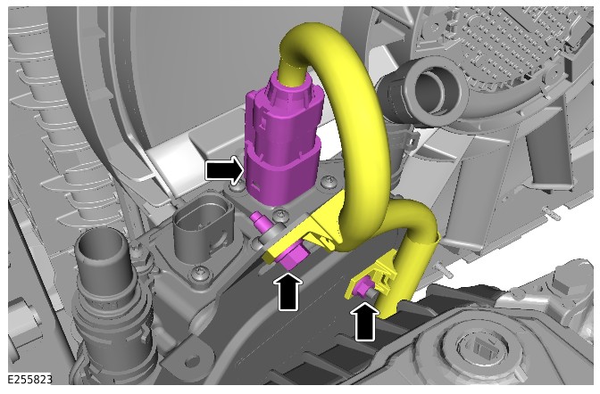
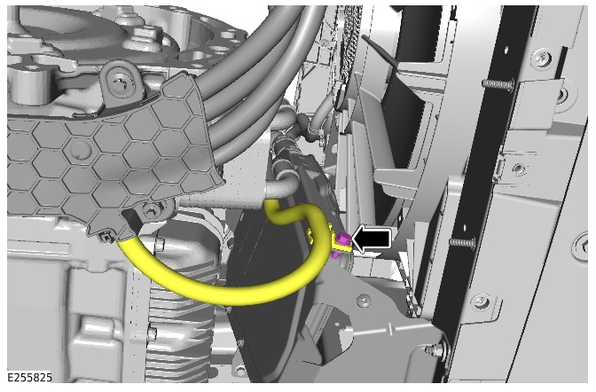
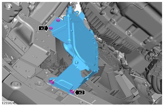
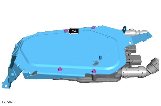
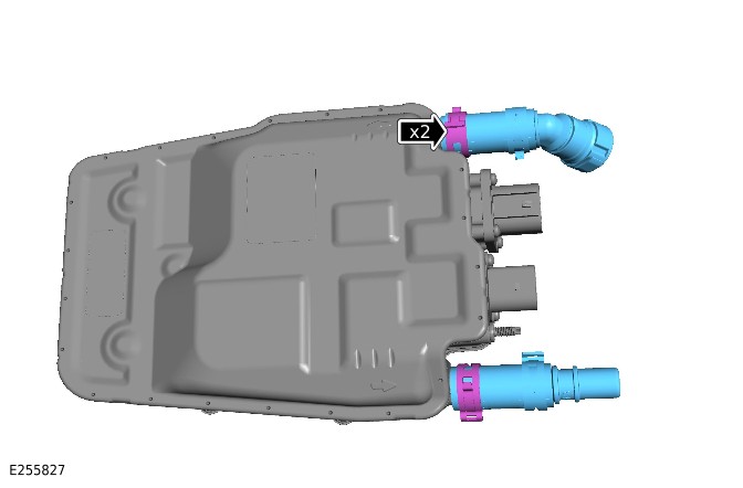
Installation
- Install the 2 coolant hoses.
- Install the 2 coolant hose clamps.
- Install the bracket.
- Install and tighten the 4 bolts.Torque: 8Nm
- Install the HV coolant heater.
- Install and tighten the 2 nuts and 2 bolts.Torque: 10Nm
- Connect the ground cable.Torque: 8Nm
- Install the wiring harness to the 2 clips.
- Use General Equipment Fluke 1507 Insulation Tester to complete the EV bonding test.General Equipment: Fluke 1507 Insulation Tester
- A) Connect the probe to the casing of HV coolant heater.
- B) Connect the probe to the ground point.
- The bonding test can only be passed if a reading of under 50 milliohms is achieved. Any measurement above this must be investigated.
- Reposition the HV cable in the correct location.
- Install and tighten the bolt.Torque: 10Nm
- Connect the HV cable connector.
- Install and tighten the nut and bolt.Torque: 10Nm
- Connect the electrical connector.
- Connect the 2 coolant hoses.
- Remove the 2 hose clamps.
- Install the air filter housing.Refer to: Air Filter Housing (303-12C Intake Air Distribution and Filtering - INGENIUM I3 1.5L Petrol, Removal and Installation).
- Install the engine undershield.Refer to: Engine Undershield (501-02 Front End Body Panels, Removal and Installation).
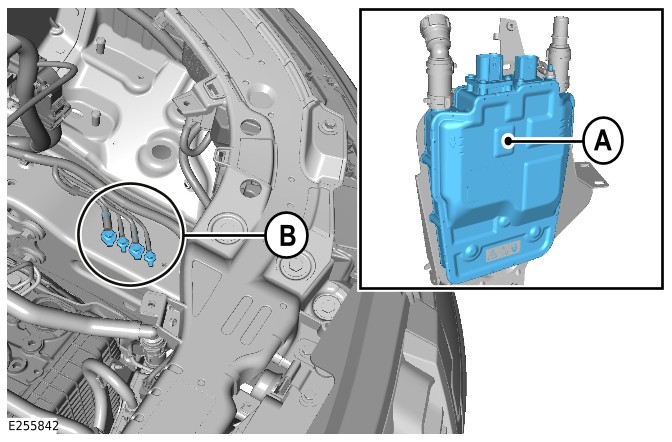
Auxiliary Battery - RBoM (G4347156)
Part(s)
All vehicles
| Name | Quantity | Part Number | ||||||
|---|---|---|---|---|---|---|---|---|
| Auxiliary Battery (Main Component) | 1 |
|
Special Tool(s)
Plug in hybrid electric vehicles only
| 12 Volt Battery Lock-offJLR-415-133 | |
| Universal Cable Lock-offJLR-415-132 | |
Repair
Auxiliary Battery (414-01C REMOVAL AND INSTALLATION G2784312)
Published: 30-Oct-2024
2022.0 New Range Rover Evoque (LZ), 414-01C
Battery, Mounting and Cables - PHEV
Auxiliary Battery (G2784312)
REMOVAL AND INSTALLATION
- 86.15.03
- auxiliary battery - renew
- All Derivatives
- 0.50
- USED WITHINS
Removal
NOTE:
- This procedure contains some variation in the illustrations depending on the vehicle specification, but the essential information is always correct.
- This procedure contains illustrations with components removed to provide extra clarity.
- This procedure contains illustrations for right hand drive vehicles, left hand drive vehicles are similar.
- Disconnect the 12V system.Refer to: 12V System Disconnect (414-00 Battery and Charging System - General Information, General Procedures).
- Remove the cowl panel.Refer to: Cowl Panel (501-02 Front End Body Panels, Removal and Installation).
- Remove the nut.
- Release the auxiliary junction box.
- Release the auxiliary battery terminal access cover.
- Disconnect the auxiliary battery positive cable.
Remove the auxiliary battery junction box.
- Disconnect the breather pipe.
- Disconnect the auxiliary battery ground cable.
- Remove the nut.
- Remove the auxiliary battery clamp.
Remove the auxiliary battery.
Remove the battery heat shield.
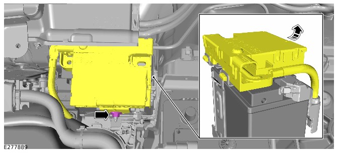
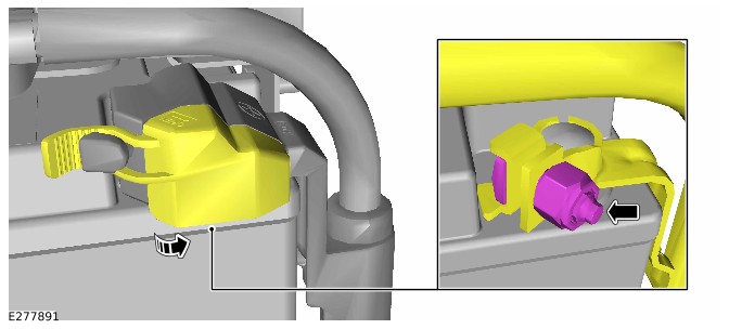
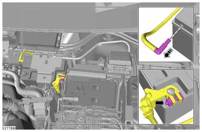
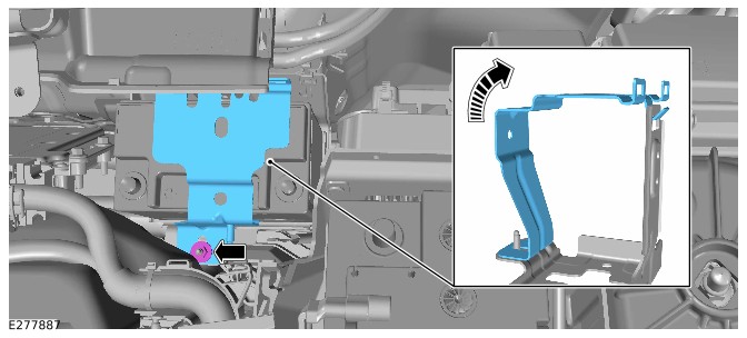
Installation
- Install the battery heat shield.
- Install the auxiliary battery.
- Install the auxiliary battery clamp.
- Install and tighten the nut.Torque: 10Nm
- Connect the breather pipe.
- Connect the auxiliary battery ground cable.Torque: 6Nm
- Connect the auxiliary battery positive cable.Torque: 6Nm
- Install the auxiliary battery terminal access cover.
- Install the auxiliary battery junction box.
- Install and tighten the nut.Torque: 10Nm
- Install the cowl panel.Refer to: Cowl Panel (501-02 Front End Body Panels, Removal and Installation).
- Connect the 12V system.Refer to: 12V System Disconnect (414-00 Battery and Charging System - General Information, General Procedures).
High Voltage Integrated Box - RBoM (G4657115)
Part(s)
All vehicles
| Name | Quantity | Part Number |
|---|---|---|
| Exhaust downpipe gasket | 1 | LR094164 |
| Exhaust downpipe nut(s) | 3 | FX108046 |
| High Voltage Integrated Box (Main Component) | 1 | LR184804 |
Special Tool(s)
All vehicles
| 12 Volt Battery Lock-offJLR-415-133 | |
| Adaptor, Cooling System Vacuum Refill KitJLR-303-1634 | |
| Break Out Box - High Voltage (HV) Auxiliary Circuit ConnectorJLR-415-136 | |
| Break Out Box Safety Check Connector – High Voltage (HV) Auxiliary Circuit ConnectorJLR-415-137 | |
| Coolant System Vacuum Refill KitHU-919 | |
| Lock Off - High Voltage (HV) Auxiliary CircuitJLR-415-115 | |
| Main High Voltage (HV) Connector Lock-offJLR-415-114 | |
| Main High Voltage connector break-out boxJLR-415-134 | |
| Main High Voltage connector break-out box safety check connectorJLR-415-135 | |
| Master Service Disconnect (MSD) Lock-off (CATL Battery)JLR-415-116 | |
| Master Service Disconnect (MSD) Lock-off (SDI Battery)JLR-415-117 | |
| Measurement Probes (GS38)JLR-415-092 | |
| Protective StickerJLR-415-024 | |
| Universal Cable Lock-offJLR-415-132 | |
| Voltage IndicatorC.A 773 | |
| Voltage Tester Proving UnitPU690 | |
Repair
High Voltage Integrated Box (414-01C REMOVAL AND INSTALLATION G2408937)
Published: 12-Jan-2023
2022.0 New Range Rover Evoque (LZ), 414-01C
Battery, Mounting and Cables - PHEV
High Voltage Integrated Box (G2408937)
REMOVAL AND INSTALLATION
- 15.10.79
- High Voltage Integrated Box - renew
- 1500 cc, Ingenium PHEV
- 4.30
- USED WITHINS
General Equipment
| Equipment name |
|---|
| Fluke 1507 Insulation Tester |
| High Level Supplementary Support Stand |
| Jaguar Land Rover approved diagnostic equipment |
Removal
WARNING:
- It is the responsibility of the Electric Vehicle Authorised Person (EVAP) to make sure they comply with any local legislation for work on High Voltage (HV).
- The approved Personal Protective Equipment (PPE) must be worn where indicated within this procedure and not removed unless indicated within a step. All items of PPE must be checked for signs of damage before each use, if damaged, replacement PPE must be obtained before doing this procedure.
- If the vehicle has been powered down, do not power up the vehicle until all the bonding points have been tested.
CAUTIONS:
- Make sure all the HV connectors, ground points and locating points are clean and free from foreign material before disconnecting and connecting.
- Before disconnecting any components, make sure the area is clean and free from foreign material. When disconnected all openings must be sealed.
NOTE:
- All Permit To Work Permit To Work (PTW) documents must be kept for a minimum of 5 years.
- This procedure contains some variation in the illustrations depending on the vehicle specification, but the essential information is always correct.
- This procedure contains illustrations showing certain components removed to provide extra clarity.
- CAUTION:
Do not handle the HV integrated box by the coolant pipes or electrical connectors.
- It is mandated that all technicians involved with the steps in this procedure have read and understood the electric vehicle safety rules.Refer to: Electric Vehicle Safety Rules (414-01C Battery, Mounting and Cables - PHEV, Description and Operation).
- Before handling any HV connectors the person(s) completing this procedure must refer to the HV electrical connector operation and inspection document.Refer to: High Voltage Electrical Connector Operation and Inspection (414-01C Battery, Mounting and Cables - PHEV, General Procedures).
- Raise and support the vehicle on a suitable 2 post lift.Refer to: Jacking and Lifting (100-02 Jacking and Lifting, Description and Operation).
- WARNING:
Jaguar Land Rover (JLR) EVAP trained technicians only.
- WARNING:
JLR Electric Vehicle Competent Person (EVCP) trained technicians only.
- Drain the Plug-in Hybrid Electric Vehicle (PHEV) battery cooling system.Refer to: PHEV Battery Cooling System Draining and Vacuum Filling (414-01C Battery, Mounting and Cables - PHEV, General Procedures).
- Remove the exhaust system.Refer to: Exhaust System (309-00D Exhaust System - INGENIUM I3 1.5L Petrol, PHEV, Removal and Installation).
- Remove the 4 nuts.
- Remove the 5 bolts.
- Remove the 2 exhaust heatshields.
- Disconnect the 3 low voltage electrical connectors.
- Remove the 2 low voltage wiring harness bracket bolts.
- Release the clip.
- Reposition the low voltage wiring harness.
- WARNING:
Be prepared to collect escaping coolant.
Disconnect the rear coolant hose.
- WARNING:
Be prepared to collect escaping coolant.
Disconnect the front coolant hose.
- Remove the ground cable bolt.
- Release the ground cable clip.
- Disconnect the breather.
- Release the clip.
Release the coolant hose clip.
Disconnect the 2 front HV cable electrical connectors.
- Remove the nut.
- Remove the bolt.
- Release the HV cable bracket from the transmission tunnel.
- Open the startup battery cable cover.
- Remove the nut and disconnect the startup battery cable.
Disconnect the 3 rear HV cable electrical connectors.
- Remove the nut and bolt.
- Reposition the high voltage cooling system inline heater away from the Belt Integrated Starter Generator (BISG) inverter assembly.
- Use a suitable stand to support the BISG inverter assembly.General Equipment: High Level Supplementary Support Stand
- Remove the 6 bolts.
- Reposition the BISG inverter assembly away from the HV integrated box assembly.
- CAUTION:
This step requires the aid of another technician.
- Remove the 6 bolts.
- Reposition the HV integrated box assembly to allow access to the coolant hose.
- Release the 4 coolant hose clips.
- Remove the HV integrated box assembly from the vehicle.
- NOTE:
Do not disassemble further if the component is removed for access only.
- Remove the 4 undershield bolts.
- Remove the HV integrated box assembly from the undershield.
- Remove the 8 bolts.
- Remove the HV integrated box brackets.
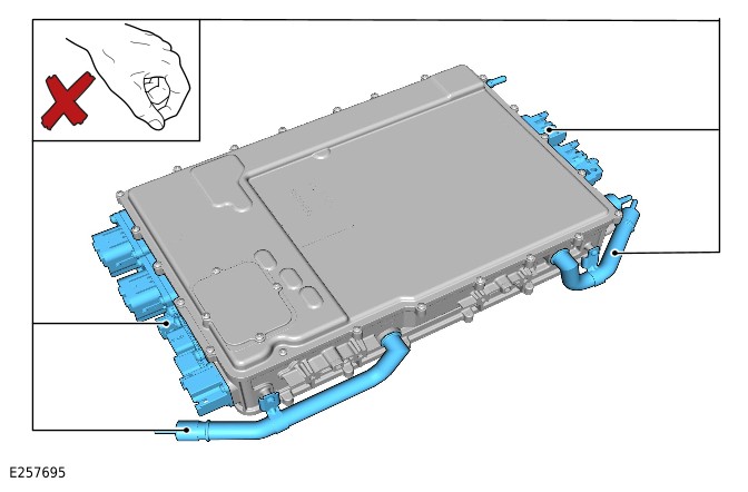
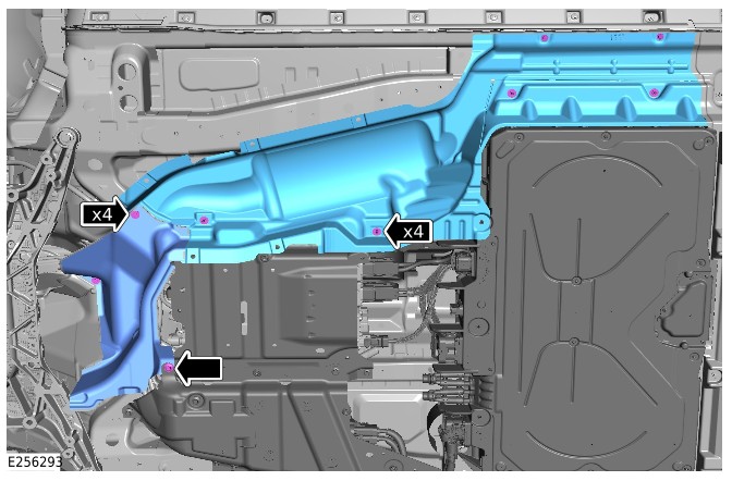
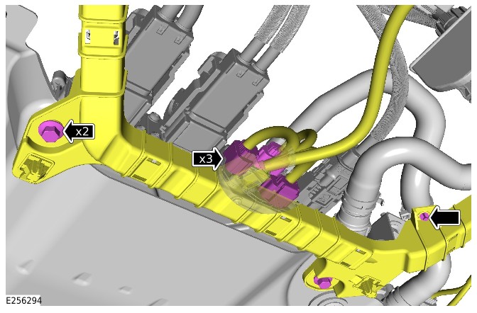
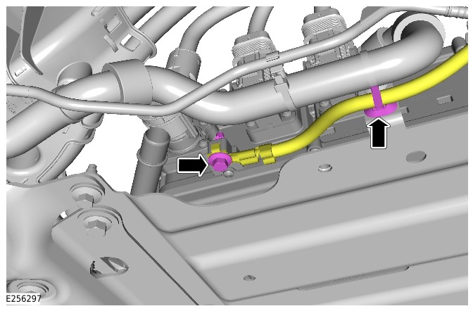
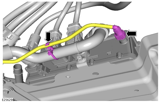
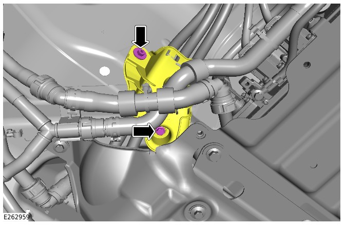
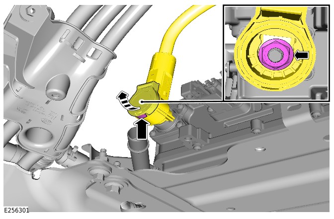
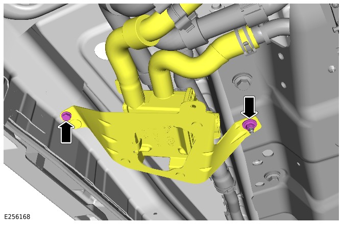
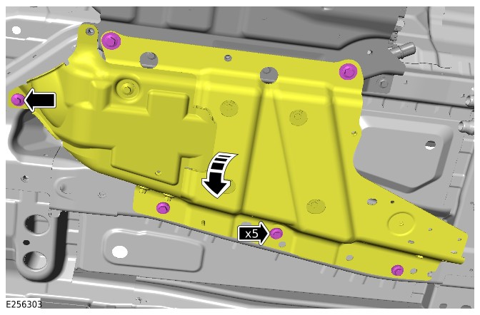
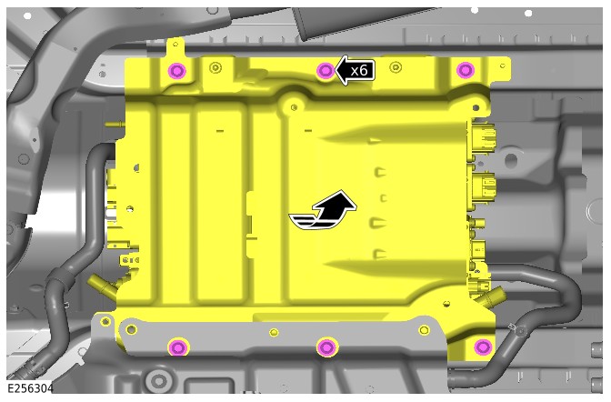
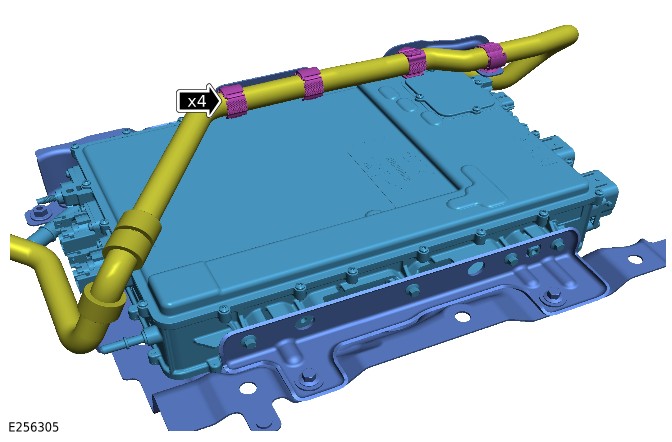
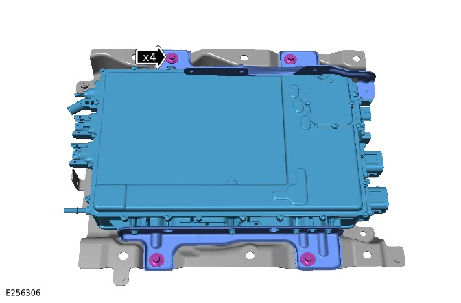
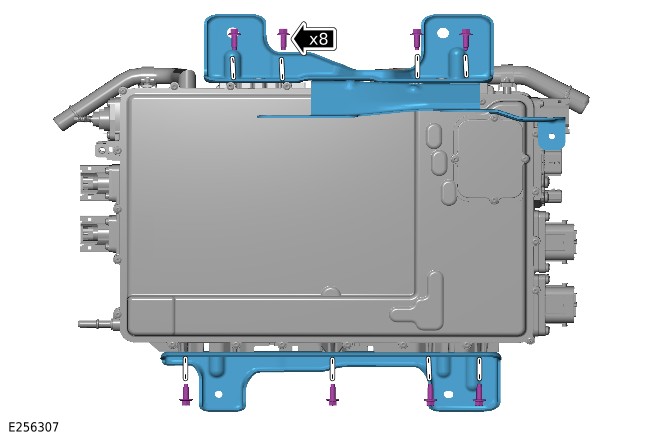
Installation
NOTE:
Only do steps 1 and 2 if previously removed.
- Install the HV integrated box brackets.
- Install and tighten the 8 bolts.Torque: 10Nm
- Install the HV integrated box assembly to the undershield.
- Install and tighten the 4 bolts.Torque: 24Nm
- CAUTION:
This step requires the aid of another technician.
- Install the HV integrated box assembly to the vehicle.
- Install the 4 coolant hose clips.
- Position the HV integrated box assembly in the correct location.
- Install and tighten the 6 bolts.Torque: 24Nm
- Install the ground cable and tighten the bolt.Torque: 10Nm
- Install the clip.
- WARNING:
Make sure the bonding test is done before the Power Up the High Voltage HV system procedure has been done.
CAUTION:The probe at point B must make contact with the High Voltage HV junction box casing.
- Use General Equipment Fluke 1507 Insulation Tester to complete the Electric Vehicle (EV) bonding test.General Equipment: Fluke 1507 Insulation Tester
- A) Connect the probe to the casing of HV integrated box.
- B) Connect the probe to the ground point.
- The bonding test can only be passed if a reading of under 50 milliohms is achieved. Any measurement above this must be investigated.
- Position the BISG inverter assembly in the correct location.
- Install and tighten the 6 bolts.TorqueM10: 60Nm M8: 30Nm
- WARNING:
Make sure the bonding test is done before the Power Up the High Voltage HV system procedure has been done.
CAUTION:The probe at point B must make contact with the High Voltage HV junction box casing.
- Use General Equipment Fluke 1507 Insulation Tester to complete the EV bonding test.General Equipment: Fluke 1507 Insulation Tester
- A) Connect the probe to the casing of BISG inverter.
- B) Connect the probe to the ground point.
- The bonding test can only be passed if a reading of under 50 milliohms is achieved. Any measurement above this must be investigated.
- Position the high voltage cooling system inline heater in the correct location.
- Install and tighten the nut and bolt.Torque: 10Nm
- Connect the 3 rear HV cable electrical connectors.
- Connect the startup battery cable and tighten the nut.Torque: 16Nm
- Close the startup battery cable cover.
- Secure the HV cable bracket to the transmission tunnel.
- Install and tighten the nut and bolt.Torque: 5.4Nm
- Connect the 2 front HV cable electrical connectors.
- Connect the breather.
- Install in the clip.
- Connect the front coolant hose.
- Secure the coolant hose clip.
- Connect the rear coolant hose.
- Position the low voltage wiring harness in the correct location.
- Connect the 3 low voltage electrical connectors.
- Install and tighten the 2 low voltage wiring harness bolts.Torque: 12Nm
- Secure in the clip.
- Install the 2 exhaust heatshields.
- Install and tighten the 5 bolts.TorqueM8: 30Nm M6: 10Nm
- Install and tighten the 4 nuts.Torque: 5.4Nm
- Install the exhaust system.Refer to: Exhaust System (309-00D Exhaust System - INGENIUM I3 1.5L Petrol, PHEV, Removal and Installation).
- WARNING:
JLR EVAP trained technicians only.
- Refill and bleed PHEV battery cooling system.Refer to: PHEV Battery Cooling System Draining and Vacuum Filling (414-01C Battery, Mounting and Cables - PHEV, General Procedures).
- If a new HV integrated box has been installed, use the JLR approved diagnostic equipment to configure the HV integrated box.General Equipment: Jaguar Land Rover approved diagnostic equipment
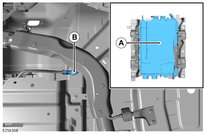
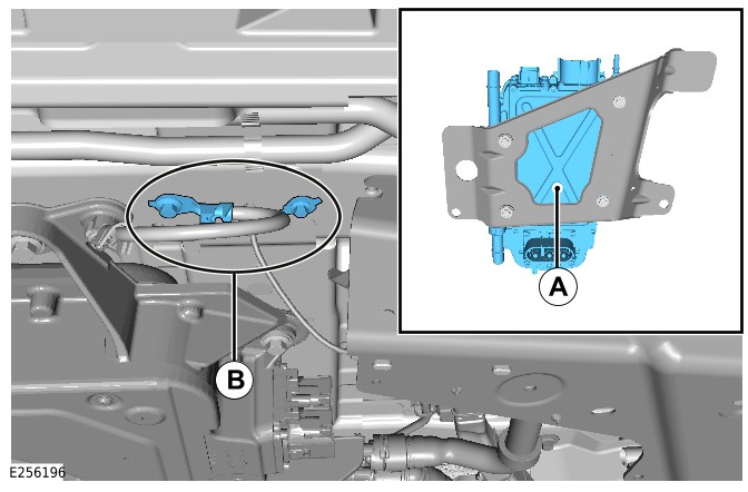
Battery Charger Control Module - Software Update - RBoM (G4657116)
Part(s)
All vehicles
| Name | Quantity | Part Number |
|---|---|---|
| High Voltage Integrated Box (Main Component) | 0 | LR184804 |
Special Tool(s)
All vehicles
| 12 Volt Battery Lock-offJLR-415-133 | |
| Adaptor, Cooling System Vacuum Refill KitJLR-303-1634 | |
| Break Out Box - High Voltage (HV) Auxiliary Circuit ConnectorJLR-415-136 | |
| Break Out Box Safety Check Connector – High Voltage (HV) Auxiliary Circuit ConnectorJLR-415-137 | |
| Coolant System Vacuum Refill KitHU-919 | |
| Lock Off - High Voltage (HV) Auxiliary CircuitJLR-415-115 | |
| Main High Voltage (HV) Connector Lock-offJLR-415-114 | |
| Main High Voltage connector break-out boxJLR-415-134 | |
| Main High Voltage connector break-out box safety check connectorJLR-415-135 | |
| Master Service Disconnect (MSD) Lock-off (CATL Battery)JLR-415-116 | |
| Master Service Disconnect (MSD) Lock-off (SDI Battery)JLR-415-117 | |
| Measurement Probes (GS38)JLR-415-092 | |
| Protective StickerJLR-415-024 | |
| Universal Cable Lock-offJLR-415-132 | |
| Voltage IndicatorC.A 773 | |
| Voltage Tester Proving UnitPU690 | |
Belt Integrated Starter Generator Inverter - RBoM (G4667847)
Part(s)
All vehicles
| Name | Quantity | Part Number | ||||||||
|---|---|---|---|---|---|---|---|---|---|---|
| Electric Power Inverter Converter (Main Component) | 1 |
|
Special Tool(s)
All vehicles
| 12 Volt Battery Lock-offJLR-415-133 | |
| Adaptor, Cooling System Vacuum Refill KitJLR-303-1634 | |
| Break Out Box - High Voltage (HV) Auxiliary Circuit ConnectorJLR-415-136 | |
| Break Out Box Safety Check Connector – High Voltage (HV) Auxiliary Circuit ConnectorJLR-415-137 | |
| Coolant System Vacuum Refill KitHU-919 | |
| Lock Off - High Voltage (HV) Auxiliary CircuitJLR-415-115 | |
| Main High Voltage (HV) Connector Lock-offJLR-415-114 | |
| Main High Voltage connector break-out boxJLR-415-134 | |
| Main High Voltage connector break-out box safety check connectorJLR-415-135 | |
| Master Service Disconnect (MSD) Lock-off (CATL Battery)JLR-415-116 | |
| Master Service Disconnect (MSD) Lock-off (SDI Battery)JLR-415-117 | |
| Measurement Probes (GS38)JLR-415-092 | |
| Protective StickerJLR-415-024 | |
| Universal Cable Lock-offJLR-415-132 | |
| Voltage IndicatorC.A 773 | |
| Voltage Tester Proving UnitPU690 | |
Repair
Belt Integrated Starter Generator Inverter (414-01C REMOVAL AND INSTALLATION G2408938)
Published: 20-May-2025
2022.0 New Range Rover Evoque (LZ), 414-01C
Battery, Mounting and Cables - PHEV
Belt Integrated Starter Generator Inverter (G2408938)
REMOVAL AND INSTALLATION
- 15.10.78
- Belt Integrated Starter Generator (BISG) Inverter
- 1500 cc, Ingenium PHEV
- 3.80
- USED WITHINS
General Equipment
| Equipment name |
|---|
| Fluke 1507 Insulation Tester |
| High Level Supplementary Support Stand |
| Jaguar Land Rover approved diagnostic equipment |
Removal
WARNING:
- It is the responsibility of the Electric Vehicle Authorized Person (EVAP) to make sure they comply with any local legislation for work on High Voltage (HV).
- The approved Personal Protective Equipment (PPE) must be worn where indicated within this procedure and not removed unless indicated within a step. All items of PPE must be checked for signs of damage before each use, if damaged, replacement PPE must be obtained before doing this procedure.
CAUTIONS:
- Make sure all the HV connectors, ground points and locating points are clean and free from foreign material before disconnecting and connecting.
- Before disconnecting any components, make sure the area is clean and free from foreign material. When disconnected all openings must be sealed.
- If the HV Belt Integrated Starter Generator (BISG) motor or the HV BISG inverter is replaced, the procedure for calibrating the motor to the HV BISG inverter must be followed.
- The calibration procedure must be followed accurately to avoid engine malfunction and dangerous vehicle behavior.
NOTE:
- All Permit To Work (PTW) documents must be kept for a minimum of 5 years.
- This procedure contains some variation in the illustrations depending on the vehicle specification, but the essential information is always correct.
- This procedure contains illustrations showing certain components removed to provide extra clarity.
- It is mandated that all technicians involved with the steps in this procedure have read and understood the Electric Vehicle (EV) Safety Rules.Refer to: Electric Vehicle Safety Rules (414-01C Battery, Mounting and Cables - PHEV, Description and Operation).
- Before handling any HV connectors the person(s) completing this procedure must refer to the 'High Voltage Electrical Connector Operation and Inspection' document.Refer to: High Voltage Electrical Connector Operation and Inspection (414-01C Battery, Mounting and Cables - PHEV, General Procedures).
- Raise and support the vehicle on a suitable 2 post lift.Refer to: Jacking and Lifting (100-02 Jacking and Lifting, Description and Operation).
- WARNING:
Jaguar Land Rover (JLR) EVAP trained technicians only.
- WARNING:
JLR Electric Vehicle Competent Person (EVCP) trained technicians only.
- Drain the engine and Electric Rear Axle Drive (eRAD) cooling system.Refer to: Engine and eRAD Cooling System Draining and Vacuum filling (303-03C Engine Cooling - INGENIUM I3 1.5L Petrol, General Procedures).
- Remove the 5 bolts.
- Remove the front HV cable electrical connector undershield.
Disconnect the front HV cable electrical connector.
- WARNING:
Be prepared to collect escaping coolant.
Disconnect the rear coolant hose.
- WARNING:
Be prepared to collect escaping coolant.
Disconnect the front coolant hose.
Disconnect the 2 Low Voltage (LV) electrical connectors.
Release the 3 LV wiring harness clips.
- Remove the nut and bolt.
- Reposition the high voltage cooling system inline heater away from the BISG inverter.
- Remove the ground cable bolt.
- Release the 2 ground cable clips.
- Use a suitable stand to support the BISG inverter.General Equipment: High Level Supplementary Support Stand
- Remove the 5 bolts.
- Lower the support stand to allow access to the top of the BISG inverter.
- Remove the HV cable bracket bolt.
- Disconnect and remove the HV electrical cable from the BISG inverter.
- Disconnect the breather pipe from the BISG inverter.
- Release the breather pipe clip.
- Release the 3 coolant pipe clips.
- Remove the BISG inverter assembly from the vehicle.
- NOTE:
Do not disassemble further if the component is removed for access only.
- Remove the 4 bolts.
- Remove the BISG mounting bracket.
- Remove the ground cable bolt.
- Remove the ground cable from the BISG inverter.
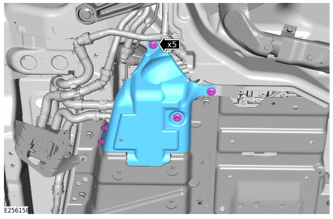
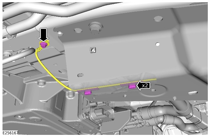
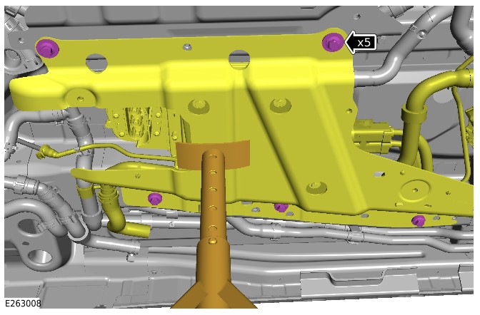
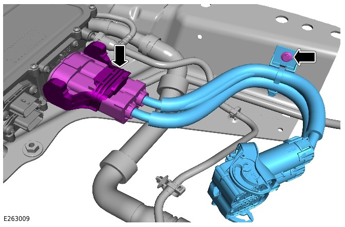
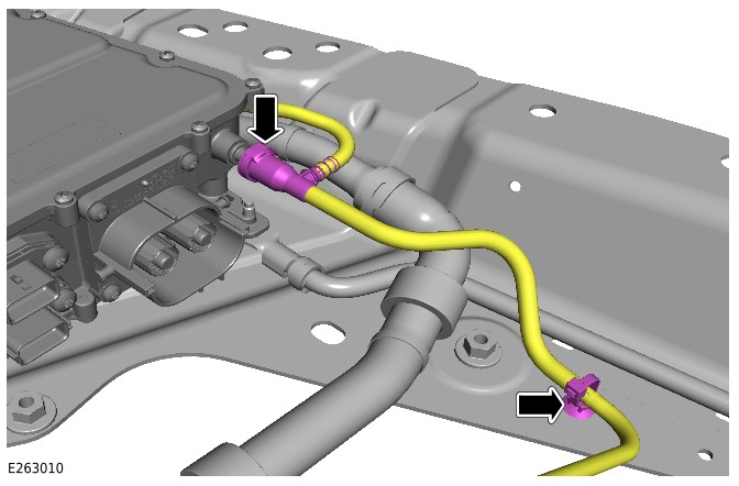
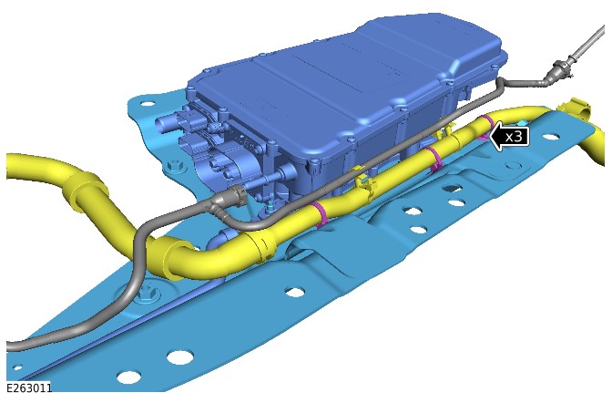
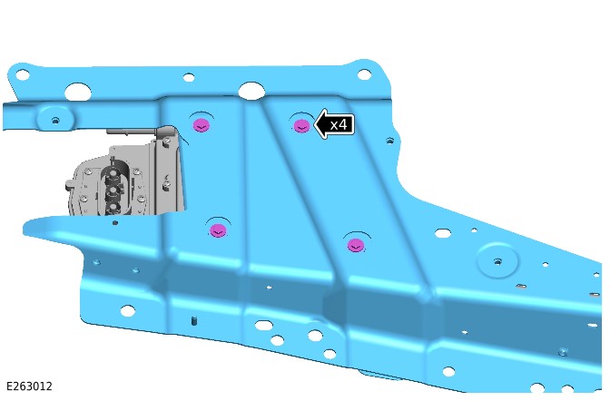
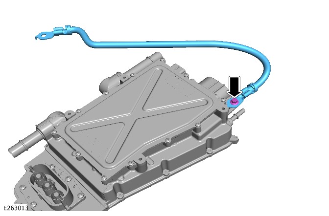
Installation
- Install the ground cable to the BISG inverter.
- Install and tighten the bolt.Torque: 10Nm
- Install the BISG mounting bracket.
- Install and tighten the 4 bolts.Torque: 10Nm
- Use a suitable stand to support the BISG inverter assembly.General Equipment: High Level Supplementary Support Stand
- Install the BISG inverter assembly to the vehicle.
- Install the 3 coolant pipe clips.
- Connect the breather pipe to the BISG inverter.
- Install the breather pipe clip.
- Install and connect the HV cable to the BISG inverter.
- Install and tighten the HV cable bracket bolt.Torque: 10Nm
- Raise the BISG assembly.
- Install and tighten the 5 bolts.Torque: 60Nm
- Lower the supporting stand away from the BISG assembly and reposition away from the vehicle.
- Install the 2 ground cable clips.
- Install and tighten the ground cable bolt.Torque: 10Nm
- Use General Equipment Fluke 1507 Insulation Tester to complete the EV bonding test.General Equipment: Fluke 1507 Insulation Tester
- A) Connect the probe to the casing of BISG inverter.
- B) Connect the probe to the ground point.
- The bonding test can only be passed if a reading of under 50 milliohms is achieved. Any measurement above this must be investigated.
- Position the high voltage cooling system inline heater in the correct location.
- Install and tighten the nut and bolt.Torque: 10Nm
- Connect the 2 LV electrical connectors.
- Install the 3 LV wiring harness clips.
- Connect the front coolant hose.
- Connect the rear coolant hose.
- Connect the front HV cable electrical connector.
- Install the front HV cable electrical connector undershield.
- Install and tighten the 5 bolts.Torque: 30Nm
- WARNING:
JLR EVAP trained technicians only.
- Refill and bleed the engine and eRAD cooling system.Refer to: Engine and eRAD Cooling System Draining and Vacuum filling (303-03C Engine Cooling - INGENIUM I3 1.5L Petrol, General Procedures).
- If a new BISG inverter has been installed, use the JLR approved diagnostic equipment to configure the BISG inverter.General Equipment: Jaguar Land Rover approved diagnostic equipment
Electric Power Inverter Converter 'B' (EPICB) - Software Update - RBoM (G4667848)
Part(s)
All vehicles
| Name | Quantity | Part Number | ||||||||
|---|---|---|---|---|---|---|---|---|---|---|
| Electric Power Inverter Converter (Main Component) | 0 |
|
Special Tool(s)
All vehicles
| 12 Volt Battery Lock-offJLR-415-133 | |
| Adaptor, Cooling System Vacuum Refill KitJLR-303-1634 | |
| Break Out Box - High Voltage (HV) Auxiliary Circuit ConnectorJLR-415-136 | |
| Break Out Box Safety Check Connector – High Voltage (HV) Auxiliary Circuit ConnectorJLR-415-137 | |
| Coolant System Vacuum Refill KitHU-919 | |
| Lock Off - High Voltage (HV) Auxiliary CircuitJLR-415-115 | |
| Main High Voltage (HV) Connector Lock-offJLR-415-114 | |
| Main High Voltage connector break-out boxJLR-415-134 | |
| Main High Voltage connector break-out box safety check connectorJLR-415-135 | |
| Master Service Disconnect (MSD) Lock-off (CATL Battery)JLR-415-116 | |
| Master Service Disconnect (MSD) Lock-off (SDI Battery)JLR-415-117 | |
| Measurement Probes (GS38)JLR-415-092 | |
| Protective StickerJLR-415-024 | |
| Universal Cable Lock-offJLR-415-132 | |
| Voltage IndicatorC.A 773 | |
| Voltage Tester Proving UnitPU690 | |
Repair
Belt Integrated Starter Generator Inverter (414-01C REMOVAL AND INSTALLATION G2408938)
Published: 20-May-2025
2022.0 New Range Rover Evoque (LZ), 414-01C
Battery, Mounting and Cables - PHEV
Belt Integrated Starter Generator Inverter (G2408938)
REMOVAL AND INSTALLATION
- 15.10.78
- Belt Integrated Starter Generator (BISG) Inverter
- 1500 cc, Ingenium PHEV
- 3.80
- USED WITHINS
General Equipment
| Equipment name |
|---|
| Fluke 1507 Insulation Tester |
| High Level Supplementary Support Stand |
| Jaguar Land Rover approved diagnostic equipment |
Removal
WARNING:
- It is the responsibility of the Electric Vehicle Authorized Person (EVAP) to make sure they comply with any local legislation for work on High Voltage (HV).
- The approved Personal Protective Equipment (PPE) must be worn where indicated within this procedure and not removed unless indicated within a step. All items of PPE must be checked for signs of damage before each use, if damaged, replacement PPE must be obtained before doing this procedure.
CAUTIONS:
- Make sure all the HV connectors, ground points and locating points are clean and free from foreign material before disconnecting and connecting.
- Before disconnecting any components, make sure the area is clean and free from foreign material. When disconnected all openings must be sealed.
- If the HV Belt Integrated Starter Generator (BISG) motor or the HV BISG inverter is replaced, the procedure for calibrating the motor to the HV BISG inverter must be followed.
- The calibration procedure must be followed accurately to avoid engine malfunction and dangerous vehicle behavior.
NOTE:
- All Permit To Work (PTW) documents must be kept for a minimum of 5 years.
- This procedure contains some variation in the illustrations depending on the vehicle specification, but the essential information is always correct.
- This procedure contains illustrations showing certain components removed to provide extra clarity.
- It is mandated that all technicians involved with the steps in this procedure have read and understood the Electric Vehicle (EV) Safety Rules.Refer to: Electric Vehicle Safety Rules (414-01C Battery, Mounting and Cables - PHEV, Description and Operation).
- Before handling any HV connectors the person(s) completing this procedure must refer to the 'High Voltage Electrical Connector Operation and Inspection' document.Refer to: High Voltage Electrical Connector Operation and Inspection (414-01C Battery, Mounting and Cables - PHEV, General Procedures).
- Raise and support the vehicle on a suitable 2 post lift.Refer to: Jacking and Lifting (100-02 Jacking and Lifting, Description and Operation).
- WARNING:
Jaguar Land Rover (JLR) EVAP trained technicians only.
- WARNING:
JLR Electric Vehicle Competent Person (EVCP) trained technicians only.
- Drain the engine and Electric Rear Axle Drive (eRAD) cooling system.Refer to: Engine and eRAD Cooling System Draining and Vacuum filling (303-03C Engine Cooling - INGENIUM I3 1.5L Petrol, General Procedures).
- Remove the 5 bolts.
- Remove the front HV cable electrical connector undershield.
- WARNING:
Be prepared to collect escaping coolant.
- WARNING:
Be prepared to collect escaping coolant.
- Remove the nut and bolt.
- Reposition the high voltage cooling system inline heater away from the BISG inverter.
- Remove the ground cable bolt.
- Release the 2 ground cable clips.
- Use a suitable stand to support the BISG inverter.General Equipment: High Level Supplementary Support Stand
- Remove the 5 bolts.
- Lower the support stand to allow access to the top of the BISG inverter.
- Remove the HV cable bracket bolt.
- Disconnect and remove the HV electrical cable from the BISG inverter.
- Disconnect the breather pipe from the BISG inverter.
- Release the breather pipe clip.
- Release the 3 coolant pipe clips.
- Remove the BISG inverter assembly from the vehicle.
- NOTE:
Do not disassemble further if the component is removed for access only.
- Remove the 4 bolts.
- Remove the BISG mounting bracket.
- Remove the ground cable bolt.
- Remove the ground cable from the BISG inverter.
Installation
- Install the ground cable to the BISG inverter.
- Install and tighten the bolt.Torque: 10Nm
- Install the BISG mounting bracket.
- Install and tighten the 4 bolts.Torque: 10Nm
- Use a suitable stand to support the BISG inverter assembly.General Equipment: High Level Supplementary Support Stand
- Install the BISG inverter assembly to the vehicle.
- Install the 3 coolant pipe clips.
- Connect the breather pipe to the BISG inverter.
- Install the breather pipe clip.
- Install and connect the HV cable to the BISG inverter.
- Install and tighten the HV cable bracket bolt.Torque: 10Nm
- Raise the BISG assembly.
- Install and tighten the 5 bolts.Torque: 60Nm
- Lower the supporting stand away from the BISG assembly and reposition away from the vehicle.
- Install the 2 ground cable clips.
- Install and tighten the ground cable bolt.Torque: 10Nm
- Use General Equipment Fluke 1507 Insulation Tester to complete the EV bonding test.General Equipment: Fluke 1507 Insulation Tester
- A) Connect the probe to the casing of BISG inverter.
- B) Connect the probe to the ground point.
- The bonding test can only be passed if a reading of under 50 milliohms is achieved. Any measurement above this must be investigated.
- Position the high voltage cooling system inline heater in the correct location.
- Install and tighten the nut and bolt.Torque: 10Nm
- Connect the 2 LV electrical connectors.
- Install the 3 LV wiring harness clips.
- Connect the front coolant hose.
- Connect the rear coolant hose.
- Connect the front HV cable electrical connector.
- Install the front HV cable electrical connector undershield.
- Install and tighten the 5 bolts.Torque: 30Nm
- WARNING:
JLR EVAP trained technicians only.
- Refill and bleed the engine and eRAD cooling system.Refer to: Engine and eRAD Cooling System Draining and Vacuum filling (303-03C Engine Cooling - INGENIUM I3 1.5L Petrol, General Procedures).
- If a new BISG inverter has been installed, use the JLR approved diagnostic equipment to configure the BISG inverter.General Equipment: Jaguar Land Rover approved diagnostic equipment
PHEV Battery - RBoM (G4681240)
Part(s)
All vehicles
| Name | Quantity | Part Number | ||||||||||||||||||
|---|---|---|---|---|---|---|---|---|---|---|---|---|---|---|---|---|---|---|---|---|
| Exhaust downpipe gasket | 1 | LR094164 | ||||||||||||||||||
| Exhaust downpipe nut(s) | 3 | FX108046 | ||||||||||||||||||
| PHEV Battery (Main Component) | 1 |
|
Special Tool(s)
All vehicles
| 12 Volt Battery Lock-offJLR-415-133 | |
| Adaptor, Cooling System Vacuum Refill KitJLR-303-1634 | |
| Break Out Box - High Voltage (HV) Auxiliary Circuit ConnectorJLR-415-136 | |
| Break Out Box Safety Check Connector – High Voltage (HV) Auxiliary Circuit ConnectorJLR-415-137 | |
| Coolant System Vacuum Refill KitHU-919 | |
| Lock Off - High Voltage (HV) Auxiliary CircuitJLR-415-115 | |
| Main High Voltage (HV) Connector Lock-offJLR-415-114 | |
| Main High Voltage connector break-out boxJLR-415-134 | |
| Main High Voltage connector break-out box safety check connectorJLR-415-135 | |
| Major unit removal trolley lifting kitJLR-415-012-02 | 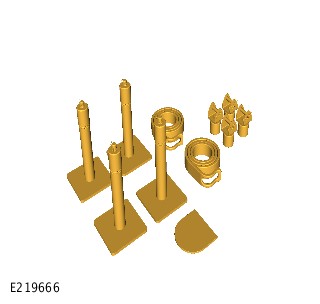 |
| Master Service Disconnect (MSD) Lock-off (CATL Battery)JLR-415-116 | |
| Master Service Disconnect (MSD) Lock-off (SDI Battery)JLR-415-117 | |
| Measurement Probes (GS38)JLR-415-092 | |
| Protective StickerJLR-415-024 | |
| Universal Cable Lock-offJLR-415-132 | |
| Voltage IndicatorC.A 773 | |
| Voltage Tester Proving UnitPU690 | |
Repair
PHEV Battery (414-01C REMOVAL AND INSTALLATION G2408941)
Published: 12-Apr-2024
2022.0 New Range Rover Evoque (LZ), 414-01C
Battery, Mounting and Cables - PHEV
PHEV Battery (G2408941)
REMOVAL AND INSTALLATION
- 15.10.13
- High Voltage Battery Pack - Renew
- 1500 cc, Ingenium PHEV
- 3.60
- USED WITHINS
Removal
NOTE:
If the Plug-in Hybrid Electric Vehicle (PHEV) battery pack is being replaced a printed copy of the State Of Charge (SOC) report must be placed in the old PHEV battery pack return packaging.
- Complete the PHEV battery identification procedure.Refer to: PHEV Battery Identification (414-01C Battery, Mounting and Cables - PHEV, General Procedures).
- Remove the CATL PHEV battery.Refer to: PHEV Battery (414-05A High Voltage (HV) Battery and Internals - Vehicles With: CATL Battery, Removal and Installation).
- Remove the SDI PHEV battery.Refer to: PHEV Battery (414-05B High Voltage (HV) Battery and Internals - Vehicles With: SDI Battery, Removal and Installation).
Installation
- Install the CATL PHEV battery.Refer to: PHEV Battery (414-05A High Voltage (HV) Battery and Internals - Vehicles With: CATL Battery, Removal and Installation).
- Install the SDI PHEV battery.Refer to: PHEV Battery (414-05B High Voltage (HV) Battery and Internals - Vehicles With: SDI Battery, Removal and Installation).
Battery, Mounting and Cables - PHEV
High Voltage Electrical Connector Operation and Inspection (G2476470)
GENERAL PROCEDURES
Activation
WARNING:
The High Voltage (HV) electrical connectors must only be disconnected after the vehicle power down procedure has been completed.
CAUTION:
Make sure all the HV connectors, ground points and locating points are clean and free from foreign material before disconnecting and connecting.
NOTE:
The illustrations in this document show all of the HV electrical connectors that are used on this vehicle in their normal working condition.
- NOTE:
After installing the HV electrical connector, perform a pull check to make sure correct latching of the electrical connector has been achieved.
- Release the electrical connector locking tab in the direction as illustrated.
- Lift the electrical connector locking arm in the direction as illustrated.
- Release the electrical connector locking arm in the direction as illustrated.
- Remove the electrical connector.
- Make sure the electrical connector seals are not damaged and are installed correctly.
- Inspect the electrical connector and make sure there is no water ingress present.
- Inspect the electrical connector terminals and make sure they are not damaged or misaligned.
- NOTE:
After installing the HV electrical connector, perform a pull check to make sure correct latching of the electrical connector has been achieved.
- Release the electrical connector locking tab in the direction as illustrated.
- Lift the electrical connector locking tab in the direction as illustrated.
- Release the electrical connector locking arm in the direction as illustrated.
- Remove the electrical connector.
- Make sure the electrical connector seals are not damaged and are installed correctly.
- Inspect the electrical connector and make sure there is no water ingress present.
- Inspect the electrical connector terminals and make sure they are not damaged or misaligned.
- NOTE:
After installing the HV electrical connector, perform a pull check to make sure correct latching of the electrical connector has been achieved.
- Release the electrical connector locking tab in the direction as illustrated.
- Release the electrical connector locking arm in the direction as illustrated.
- Remove the electrical connector.
- Make sure the electrical connector seals are not damaged and are installed correctly.
- Inspect the electrical connector and make sure there is no water ingress present.
- Inspect the electrical connector terminals and make sure they are not damaged or misaligned.
- NOTE:
After installing the HV electrical connector, perform a pull check to make sure correct latching of the electrical connector has been achieved.
- Release the electrical connector locking tab in the direction as illustrated.
- Release the electrical connector locking collar in the direction as illustrated.
- Release the electrical connector locking tab in the direction as illustrated.
- Remove the electrical connector.
- Make sure the electrical connector seals are not damaged and are installed correctly.
- Inspect the electrical connector and make sure there is no water ingress present.
- Inspect the electrical connector terminals and make sure they are not damaged or misaligned.
- NOTE:
After installing the electrical connector, perform a pull check to make sure correct latching of the electrical connector has been achieved.
- Release the electrical connector locking tab in the direction as illustrated.
- Press down the electrical connector release tab and disconnect the electrical connector.
- Make sure the electrical connector seals are not damaged and are installed correctly.
- Inspect the electrical connector and make sure there is no water ingress present.
- Inspect the electrical connector terminals and make sure they are not damaged or misaligned.
- NOTE:
After installing the HV electrical connector, perform a pull check to make sure correct latching of the electrical connector has been achieved.
Release the electrical connector by simultaneously pressing the securing tabs towards each other and disconnect the electrical connector.
- Make sure the electrical connector seals are not damaged and are installed correctly.
- Inspect the electrical connector and make sure there is no water ingress present.
- Inspect the electrical connector terminals and make sure they are not damaged or misaligned.
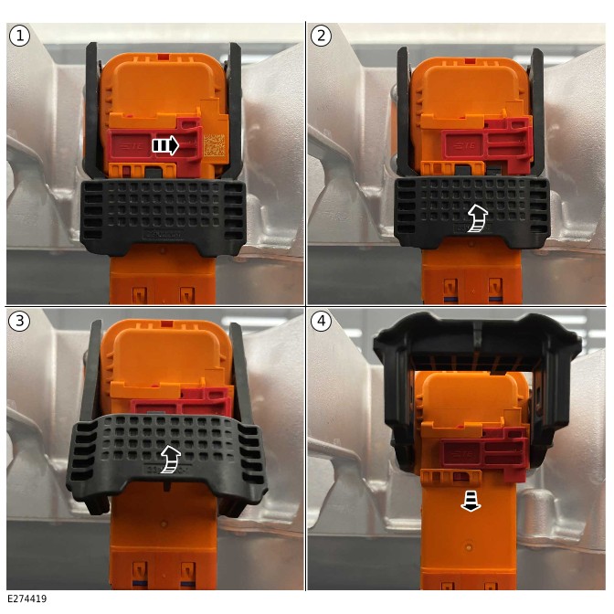
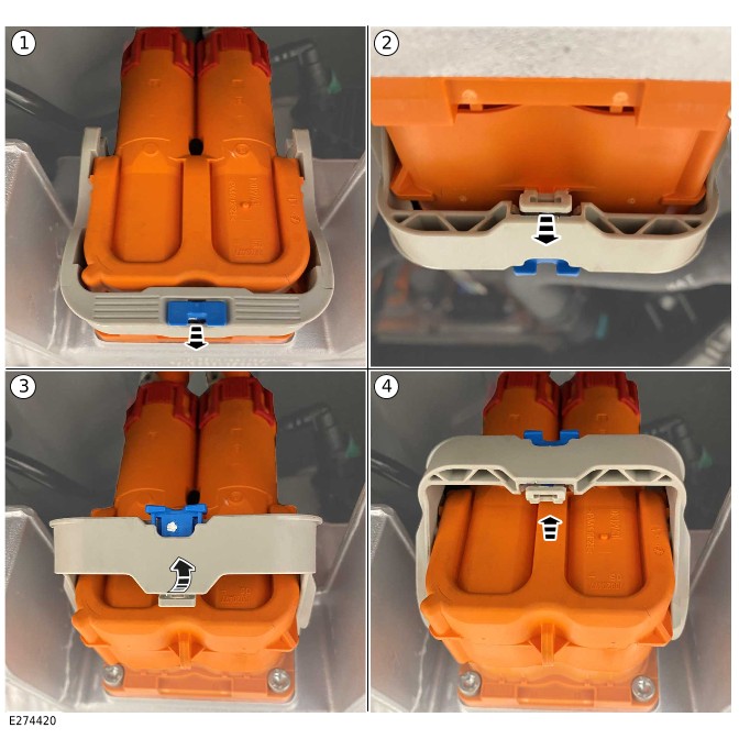
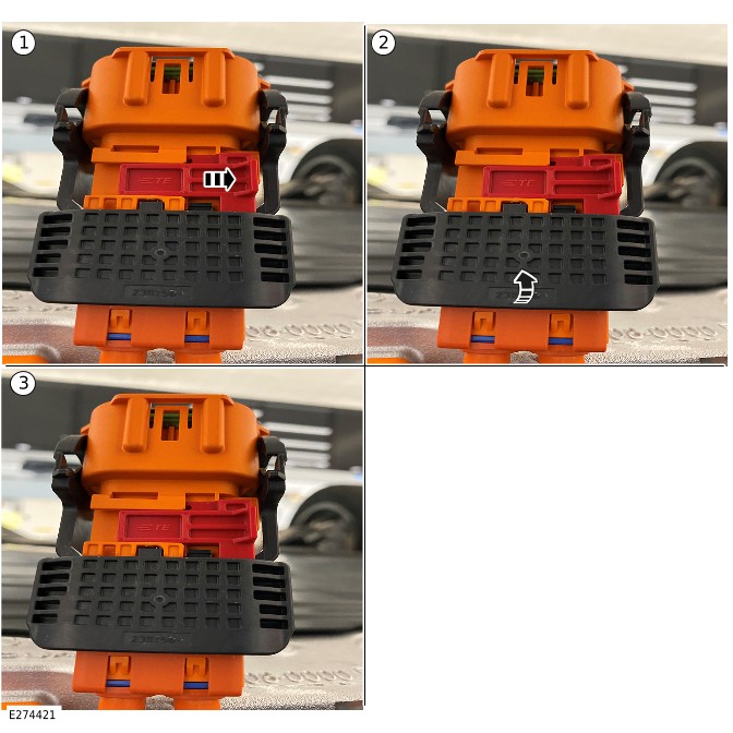
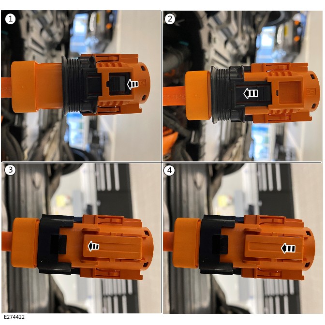
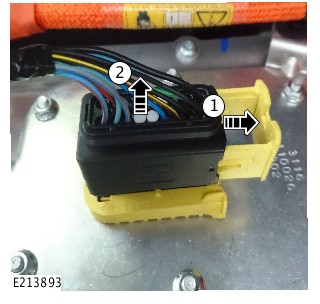
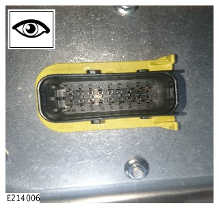
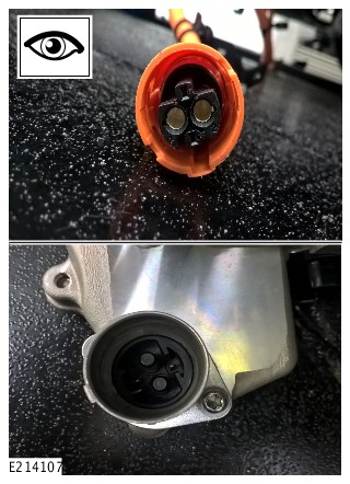
PHEV Battery Cooling System Draining and Vacuum Filling (G2435792)
GENERAL PROCEDURES
- 15.10.38
- Coolant - draining, filling and bleeding - high voltage (HV) battery pack
- 1500 cc, Ingenium PHEV
- 1.40
- USED WITHINS
Special Tool(s)
HU-919
Coolant System Vacuum Refill Kit
JLR-303-1634
Adaptor, Cooling System Vacuum Refill Kit
General Equipment
| Equipment name |
|---|
| Jaguar Land Rover approved diagnostic equipment |
Draining
WARNING:
Injury such as scalding could be caused by escaping steam or coolant. Make sure the vehicle cooling system is cool prior to carrying out this procedure.
CAUTIONS:
- The Plug-in Hybrid Electric Vehicle (PHEV) battery cooling system must be maintained with the correct concentration and type of coolant solution to prevent corrosion and frost damage. Failure to follow this instruction may result in damage to the vehicle.
- Coolant will damage the paint finished surfaces. If spilt, immediately remove the coolant and clean the area with water.
- Never remove the coolant expansion tank cap under any circumstances while the engine is operating. Failure to follow this instruction may result in damage to the engine.
NOTES:
- This procedure contains some variation in the illustrations depending on the vehicle specification, but the essential information is always correct.
- This procedure contains illustrations showing certain components removed to provide extra clarity.
- WARNING:
Injury such as scalding could be caused by escaping steam or coolant. Make sure the vehicle cooling system is cool prior to carrying out this procedure.
Remove the PHEV battery cooling system expansion tank cap.
- Raise and support the vehicle on a suitable 2 post lift.Refer to: Jacking and Lifting (100-02 Jacking and Lifting, Description and Operation).
- Remove the engine undershield.Refer to: Engine Undershield (501-02 Front End Body Panels, Removal and Installation).
- Remove the 11 bolts.
- Remove the nut.
- Remove the 9 clips.
- Remove the right undershield.
- Release the 2 PHEV battery wiring harness clips.
- Remove the 7 bolts.
- Remove the center undershield.
- Release the 2 clips and then release the 2 PHEV battery coolant pipes.
- Release the PHEV battery heater coolant pipe.
- Allow the coolant to drain into a suitable container.
- Install the 2 PHEV battery coolant pipes.
- Install the 2 coolant pipe clips.
- Install the PHEV battery heater coolant pipe.
- Install the center undershield.
- Install the 2 PHEV battery wiring harness clips.
- Install and tighten the 7 bolts.Torque: 20Nm
- Install the right undershield.
- Install the 9 clips.
- Install and tighten the nut.Torque: 7Nm
- Install and tighten the 11 bolts.TorqueM6: 4.1Nm M8: 7Nm
- Remove the front left wheel.Refer to: Wheel and Tire (204-04 Wheels and Tires, Removal and Installation).
- Remove the 8 clips.
- Reposition the front left wheel arch liner.
- Remove the 3 screws.
- Remove the front left wheel arch liner air deflector.
- Remove the 2 screws.
- Remove the front bumper lower finisher.
- Release the coolant pipe from the PHEV battery coolant pump.
- Allow the coolant to drain into a suitable container.
- Install the coolant pipe to the PHEV battery coolant pump.
- Install the front bumper lower finisher.
- Install and tighten the 2 screws.Torque: 2Nm
- Install the front left wheel arch liner air deflector.
- Install and tighten the 3 screws.Torque: 2Nm
- Reposition the front left wheel arch liner.
- Install the 8 clips.
- Install the front left wheel.Refer to: Wheel and Tire (204-04 Wheels and Tires, Removal and Installation).
- Install the engine undershield.Refer to: Engine Undershield (501-02 Front End Body Panels, Removal and Installation).
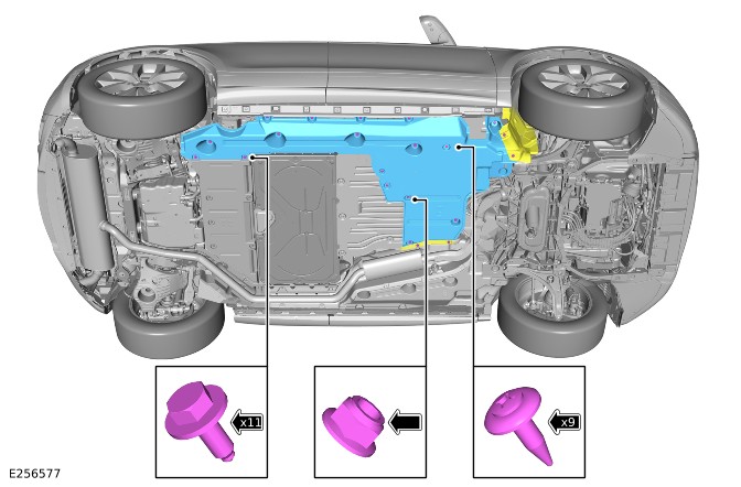
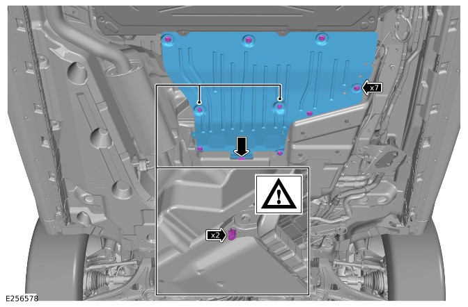
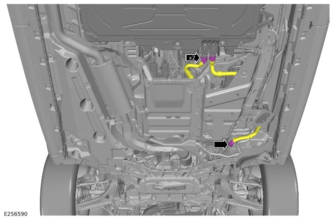
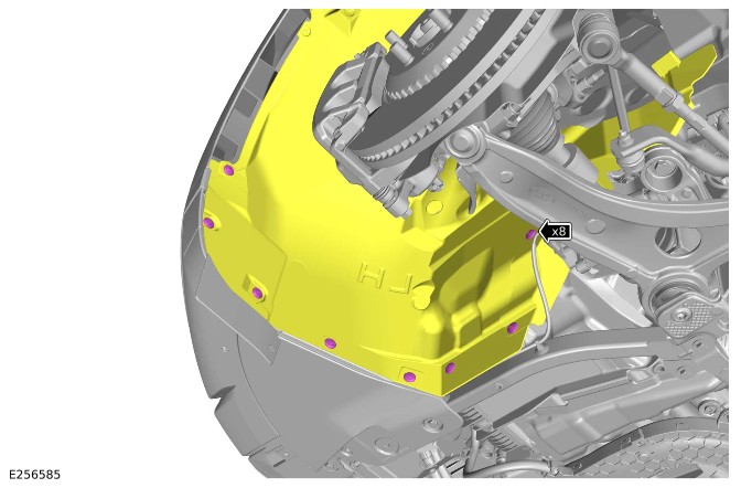

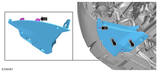
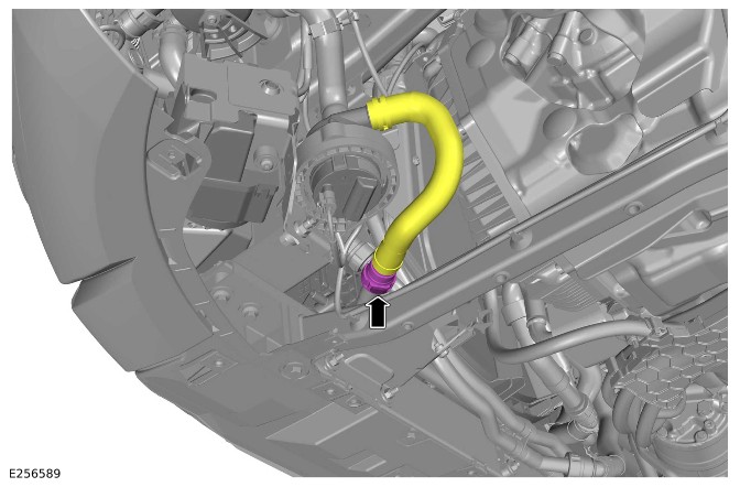
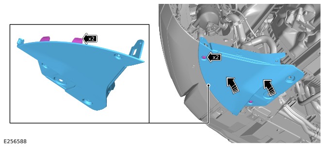
Filling
- Prepare a sufficient amount of coolant meeting Jaguar Land Rover (JLR) Electric Vehicle (EV) specifications.Refer to: Specifications (303-03C Engine Cooling - INGENIUM I3 1.5L Petrol, Specifications).
- Install the special tool HU-919 and JLR-303-1634 to the PHEV battery cooling system expansion tank.Special Tool(s): HU-919, JLR-303-1634
- NOTES:
- The special tool HU-919 needs an air pressure of 6 bar to 8 bar (87 psi to 116 psi) to operate correctly.
- Small diameter or long airlines may restrict airflow to the HU-919 vacuum refill tool.
- Close the coolant inlet valve (A) and air supply valve (B) on the special tool HU-919.
- Attach the coolant inlet hose (C) from a container of coolant mixture to the special tool HU-919.
- Connect a regulated compressed air supply (D) to the special tool HU-919.
- Open the air supply valve until -0.8 Bar is shown on the gauge.Special Tool(s): HU-919
- If -0.8 Bar is displayed on the vacuum refill tool HU-919 gauge, close the air supply valve.Special Tool(s): HU-919
- Wait 1 minute to check if the PHEV battery cooling system holds the vacuum. If the PHEV battery cooling system does not hold the vacuum, check the pipe connections and system components.
- Open the coolant supply valve and allow the coolant to be drawn into the system.Special Tool(s): HU-919
- Close the coolant supply valve when the PHEV battery cooling system expansion tank 'MAX' mark is reached or coolant movement has ceased.
- Close the coolant supply valve (A) air supply valve (B) on the special tool HU-919.Special Tool(s): HU-919
- Release the air supply (D) and the coolant inlet hose (C) from the special tool HU-919.Special Tool(s): HU-919
Remove the special tools HU-919 and JLR-303-1634 from the PHEV battery cooling system expansion tank.Special Tool(s): HU-919, JLR-303-1634
- If required, fill the PHEV battery cooling system expansion tank to the 'MAX' mark.
- Install the PHEV battery cooling system expansion tank cap.
- Using the Jaguar Land Rover approved diagnostic equipment, run the EV battery coolant fill application.General Equipment: Jaguar Land Rover approved diagnostic equipment
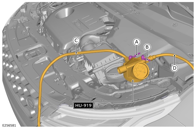
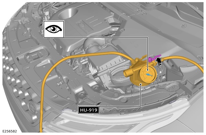
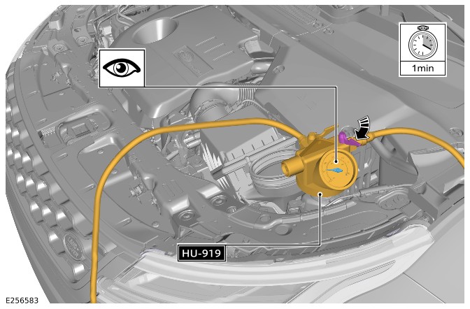
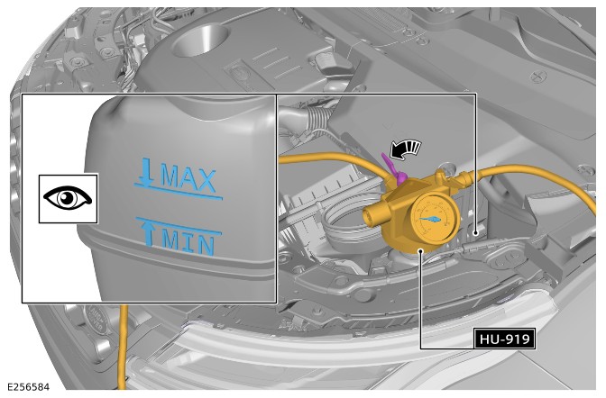
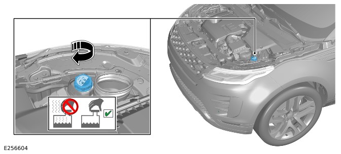
PHEV Battery Handling and Storage (G2453422)
GENERAL PROCEDURES
- 01.01.48
- Hybrid / Electric Vehicle (EV) Battery Handling and Storage
- 1500 cc, Ingenium PHEV
- 0.10
- USED WITHINS
Special Tool(s)
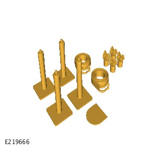
JLR-415-012-02
Major unit removal trolley lifting kit
General Equipment
| Equipment name |
|---|
| Engine hoist (1 tonne minimum capacity) |
Check
WARNING:
It is the responsibility of the Electric Vehicle Authorised Person (EVAP) to make sure they comply with any local legislation for work on High Voltage (HV) systems.
The approved Personal Protection Equipment Personal Protective Equipment (PPE) must be worn throughout the steps in this procedure and not removed at any time. All items of PPE must be checked for signs of damage before use. If damaged, replacement PPE must be obtained before doing these steps.
- Cotton clothing
- Class 0 insulated rubber gloves
- Class 0 insulated safety visor.
CAUTIONS:
- Make sure all the HV connectors, ground points and locating points are clean and free from foreign material before disconnecting and connecting.
- Before disconnecting any components, make sure the area is clean and free from foreign material. When disconnected all openings must be sealed.
- If the HV battery module is being replaced a printed copy of the State Of Charge (SOC) report must be placed in the old HV battery module return packaging.
NOTE:
- All Permit To Work (PTW) documents must be kept for a minimum of 5 years.
- This procedure contains some variation in the illustrations depending on the vehicle specification, but the essential information is always correct.
- This procedure contains illustrations showing certain components removed to provide extra clarity.
- WARNING:
Jaguar Land Rover (JLR) EVAP trained technicians only.
- Before handling any HV connectors the person(s) performing this procedure must refer to the HV Electrical Connector Operation and Inspection document.Refer to: High Voltage Electrical Connector Operation and Inspection (414-01C Battery, Mounting and Cables - PHEV, General Procedures).
Before moving the Plug-in Hybrid Electric Vehicle (PHEV) battery delivery box, make sure the pallet truck legs have a minimum length of 1500 mm long.
Insert the pallet truck underneath the PHEV battery delivery box as shown in the illustration.
With assistance, raise the PHEV battery delivery box and install 4 Suitable blocks to the corners of the PHEV battery delivery box.
- Remove the PHEV battery delivery box lid.
Install the special tools as illustrated.Special Tool(s): JLR-415-012-02
Using a suitable engine hoist, reposition the PHEV battery as required.General Equipment: Engine hoist (1 tonne minimum capacity)
- All lock off tools must be left installed on the PHEV battery until it has been install to the vehicle or until new PHEV battery is available.
- Store the PHEV battery in a secure location.
- Place a safety barrier around the PHEV battery, leave a minimum of a 1 meter gap between the PHEV battery and the barrier.
- Place fire suppressant equipment in close proximity of the PHEV battery.
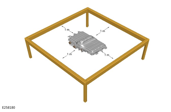
Adjustment
- WARNING:
JLR EVAP trained technicians only.
NOTE:The lock off tools shown in this step apply to Rest of World market vehicles.
Remove the lock off tools and padlocks from the assured PHEV battery and swap them over with the blanking caps on the new PHEV battery. This must be done 1 at a time to reduce the risk of electrocution.
- WARNING:
JLR EVAP trained technicians only.
NOTE:The lock off tools shown in this step apply to China market vehicles only.
Remove the lock off tools and padlocks from the assured PHEV battery and swap them over with the blanking caps on the new PHEV battery. This must be done 1 at a time to reduce the risk of electrocution.
- The assured PHEV battery and a printed copy of the battery state of charge, must now be placed immediately into the packaging that was supplied with the new PHEV battery and securely fastened.
- The assured PHEV battery must now be stored in a suitable, secure location until it is collected.
- The new PHEV battery must now be stored exactly as detailed in step 3 until it is ready to be installed to the vehicle.
PHEV Battery Identification (G2722603)
GENERAL PROCEDURES
Inspection
The Master Service Disconnect (MSD) cover is located at the front of the Plug-in Hybrid Electric Vehicle (PHEV) battery for vehicles with CATL battery.
The MSD cover is located at the rear of the PHEV battery for vehicles with SDI battery.
Electric Vehicle Quarantine (G2445016)
GENERAL PROCEDURES
Inspection
NOTE:
Discovery Sport imagery shown, Range Rover Evoque is similar.
- WARNING:
Jaguar Land Rover Electric Vehicle Authorized Person (EVAP) trained technicians only.
- WARNING:
This Step must be performed in a suitable outside location, not within a workshop.
- WARNING:
If any signs of fire or smoke are found, do not proceed any further with the procedure. Position the vehicle with ample space left between the vehicle and other vehicles, buildings and flammable or combustible objects, then contact the emergency services.
Inspect the vehicle for any signs of fire or smoke.
- WARNINGS:
- If any concerns are found with the Plug-in Hybrid Electric Vehicle (PHEV) battery, the vehicle must now be placed in quarantine, proceed to Step 5.
- If any concerns are found with any of the other HV components or cabling, the vehicle must be powered down. Proceed to Step 4.
- WARNING:
- Move the vehicle into the workshop.
- WARNINGS:
- If any concerns are found with the PHEV battery, the vehicle must now be placed in quarantine, proceed to Step 5.
- If any concerns are found with any of the other HV components or cabling, the vehicle must be powered down. Proceed to Step 4.
- WARNING:
Jaguar Land Rover EVAP trained technicians only.
Power Down the HV system. Only technicians qualified to EVAP level are allowed to perform this procedure. It is mandated that all technicians involved with the steps in this procedure have read and understood the Electric Vehicle Safety Rules.Refer to: Electric Vehicle Safety Rules (414-01C Battery, Mounting and Cables - PHEV, Description and Operation).
- Do not proceed any further with this procedure. Normal repairs / diagnosis of the vehicle can commence.
- WARNING:
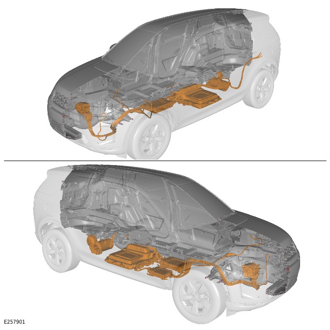
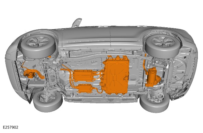
quarantine
- NOTE:
A vehicle cover can be placed over the vehicle during the quarantine period; to prevent damage to the vehicle, for example water ingress.
- The vehicle must now be positioned outside and quarantined for 48 hours, where the following conditions are met;
- Ample space must be left between the vehicle and other vehicles, buildings and flammable or combustible objects throughout the quarantine period. A distance of 15 meters (50 feet) is recommended.
- Access to the vehicle for emergency services must be maintained throughout the quarantine period.
- Access to the vehicle must be secured against unauthorized access throughout the quarantine period.
- The Warning safety sign must be displayed in the windshield on the drivers side of the vehicle throughout the quarantine period.
- A safety barrier must be placed around the vehicle, leaving a 1 meter (3 feet) gap between the vehicle and the safety barrier throughout the quarantine period.
- When the vehicle has been placed into quarantine, contact Technical Support for further information.
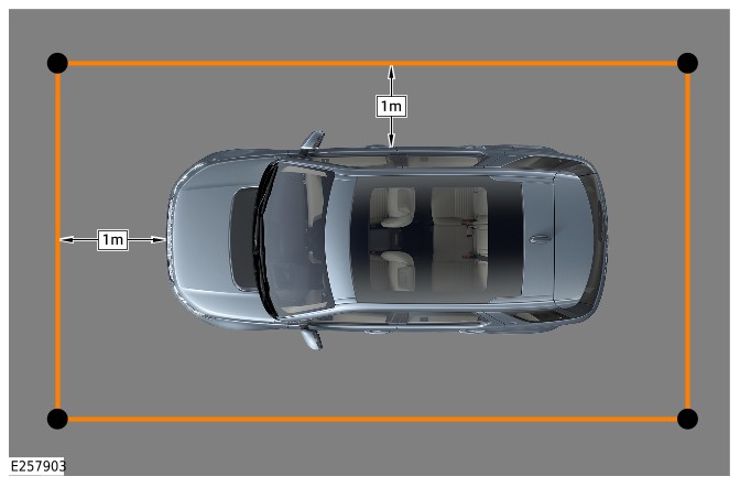
Startup Battery (G2408934)
REMOVAL AND INSTALLATION
- 86.15.01
- Startup Battery - Renew
- All Derivatives
- 0.50
- USED WITHINS
Removal
NOTE:
- This procedure contains illustrations showing certain components removed to provide extra clarity.
- This procedure contains some variation in the illustrations depending on the vehicle specification, but the essential information is always correct.
- It is mandated that all technicians involved with the steps in this procedure have read and understood the Electric Vehicle (EV) Safety Rules.Refer to: Electric Vehicle Safety Rules (414-01C Battery, Mounting and Cables - PHEV, Description and Operation).
- WARNING:
Jaguar Land Rover (JLR) Electric Vehicle Competent Person (EVCP) trained technicians only.
- Disconnect the 12V system.Refer to: 12V System Disconnect (414-00 Battery and Charging System - General Information, General Procedures).
- Remove the engine compartment cross brace.Refer to: Engine Compartment Cross Brace (501-02 Front End Body Panels, Removal and Installation).
- Remove the air filter housing.Refer to: Air Filter Housing (303-12C Intake Air Distribution and Filtering - INGENIUM I3 1.5L Petrol, Removal and Installation).
- Release the clip.
- Reposition the vacuum pipe away from the startup battery tray.
- Release the 2 clips.
- Reposition the Mass Air Flow (MAF) sensor wiring harness away from the startup battery tray.
- Release the clip.
- Reposition the transmission breather pipe away from the startup battery tray.
- Remove the startup battery tray upper trim.
- Release the 6 clips.
- Release the 4 clips.
- Remove the startup battery tray front cover.
- NOTE:
Note the installed position of the components prior to removal.
- Remove the 3 nuts.
- Disconnect the 3 cables from the Battery Junction Box (BJB).
- Release the 2 wiring harness grommets.
- Reposition the 2 wiring harnesses away from the startup battery.
- Release the wiring harness clip.
- Disconnect the startup battery positive terminal.
- Release the 4 clips.
- Reposition the BJB away from the startup battery.
- Release the startup battery vent pipe.
- Reposition the start up battery vent pipe away from the startup battery.
Installation
- Install the startup battery.
- Install and tighten the startup battery clamp.Torque: 24Nm
- Install the startup battery vent pipe.
- Reposition the BJB.
- Install the 4 clips.
- Connect the startup battery positive terminal.
- Make sure the startup battery positive terminal is correctly installed.
- Tighten the nut.Torque: 6Nm
- Install the wiring harness clip.
- Reposition the 2 wiring harnesses into the correct location.
- Install the 2 grommets.
- CAUTION:
Make sure that these components are installed to the noted removal position.
- Connect the 3 cables to the BJB.
- Install and tighten the 3 nuts.Torque: 18Nm
- Install the startup battery tray front cover.
- Install the 4 clips.
- Install the startup battery tray upper trim.
- Install the 6 clips.
- Reposition the transmission breather pipe into the correct location.
- Install the clip.
- Reposition the MAF sensor wiring harness into the correct location.
- Install the 2 clips.
- Reposition the vacuum pipe into the correct location.
- Install the clip.
- Install the air filter housing.Refer to: Air Filter Housing (303-12C Intake Air Distribution and Filtering - INGENIUM I3 1.5L Petrol, Removal and Installation).
- Install the engine compartment cross brace.Refer to: Engine Compartment Cross Brace (501-02 Front End Body Panels, Removal and Installation).
- Connect the 12V system.Refer to: 12V System Disconnect (414-00 Battery and Charging System - General Information, General Procedures).
- CAUTION:
Make sure the Battery Monitoring Sensor (BMS) electrical connector is connected to the module, before installing the BMS on to the battery terminal.
NOTE:This step is only necessary when installing a new battery.
Use Jaguar Land Rover approved diagnostic equipment to reset the BMS.
Startup Battery Tray (G2408935)
REMOVAL AND INSTALLATION
- 86.15.44
- Startup Battery Tray - Renew
- 1500 cc, Ingenium PHEV
- 0.50
- USED WITHINS
- 86.15.44.32
- Startup Battery Tray - Renew - MHEV Vehicles
- 1500 cc, INGENIUM PETROL
- 0.50
- USED WITHINS
Removal
NOTE:
- This procedure contains some variation in the illustrations depending on the vehicle specification, but the essential information is always correct.
- This procedure contains illustrations showing certain components removed to provide extra clarity.
- It is mandated that all technicians involved with the steps in this procedure have read and understood the Electric Vehicle (EV) Safety Rules.Refer to: Electric Vehicle Safety Rules (414-01 Battery, Mounting and Cables - Vehicles With: PHEV, Description and Operation).
- WARNING:
Jaguar Land Rover (JLR) Electric Vehicle Competent Person (EVCP) trained technicians only.
- Disconnect the startup battery ground cable.Refer to: 12V System Disconnect (414-00 Battery and Charging System - General Information, General Procedures).
- Remove the startup battery.Refer to: Startup Battery (414-01C Battery, Mounting and Cables - PHEV, Removal and Installation).
- Remove the 3 bolts.
- Release the wiring harness clip.
- Reposition the startup battery tray to get access to the dual battery junction box.
- Remove the 3 nuts.
- Reposition the dual battery junction box away from the startup battery tray.
- Remove the startup battery tray.
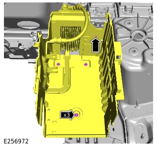
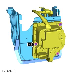
Installation
- Install the startup battery tray.
- Reposition the dual battery junction box into the correct location.
- Install and tighten the 3 nuts.Torque: 10Nm
- Secure the wiring harness clip.
- Install and tighten the 3 bolts.Torque: 10Nm
- Install the startup battery.Refer to: Startup Battery (414-01C Battery, Mounting and Cables - PHEV, Removal and Installation).
- Connect the startup battery ground cable.Refer to: 12V System Disconnect (414-00 Battery and Charging System - General Information, General Procedures).
High Voltage Integrated Box (G2408937)
REMOVAL AND INSTALLATION
- 15.10.79
- High Voltage Integrated Box - renew
- 1500 cc, Ingenium PHEV
- 4.30
- USED WITHINS
General Equipment
| Equipment name |
|---|
| Fluke 1507 Insulation Tester |
| High Level Supplementary Support Stand |
| Jaguar Land Rover approved diagnostic equipment |
Removal
WARNING:
- It is the responsibility of the Electric Vehicle Authorised Person (EVAP) to make sure they comply with any local legislation for work on High Voltage (HV).
- The approved Personal Protective Equipment (PPE) must be worn where indicated within this procedure and not removed unless indicated within a step. All items of PPE must be checked for signs of damage before each use, if damaged, replacement PPE must be obtained before doing this procedure.
- If the vehicle has been powered down, do not power up the vehicle until all the bonding points have been tested.
CAUTIONS:
- Make sure all the HV connectors, ground points and locating points are clean and free from foreign material before disconnecting and connecting.
- Before disconnecting any components, make sure the area is clean and free from foreign material. When disconnected all openings must be sealed.
NOTE:
- All Permit To Work Permit To Work (PTW) documents must be kept for a minimum of 5 years.
- This procedure contains some variation in the illustrations depending on the vehicle specification, but the essential information is always correct.
- This procedure contains illustrations showing certain components removed to provide extra clarity.
- CAUTION:
Do not handle the HV integrated box by the coolant pipes or electrical connectors.
- It is mandated that all technicians involved with the steps in this procedure have read and understood the electric vehicle safety rules.Refer to: Electric Vehicle Safety Rules (414-01C Battery, Mounting and Cables - PHEV, Description and Operation).
- Before handling any HV connectors the person(s) completing this procedure must refer to the HV electrical connector operation and inspection document.Refer to: High Voltage Electrical Connector Operation and Inspection (414-01C Battery, Mounting and Cables - PHEV, General Procedures).
- Raise and support the vehicle on a suitable 2 post lift.Refer to: Jacking and Lifting (100-02 Jacking and Lifting, Description and Operation).
- WARNING:
Jaguar Land Rover (JLR) EVAP trained technicians only.
- WARNING:
JLR Electric Vehicle Competent Person (EVCP) trained technicians only.
- Drain the Plug-in Hybrid Electric Vehicle (PHEV) battery cooling system.Refer to: PHEV Battery Cooling System Draining and Vacuum Filling (414-01C Battery, Mounting and Cables - PHEV, General Procedures).
- Remove the exhaust system.Refer to: Exhaust System (309-00D Exhaust System - INGENIUM I3 1.5L Petrol, PHEV, Removal and Installation).
- Remove the 4 nuts.
- Remove the 5 bolts.
- Remove the 2 exhaust heatshields.
- Disconnect the 3 low voltage electrical connectors.
- Remove the 2 low voltage wiring harness bracket bolts.
- Release the clip.
- Reposition the low voltage wiring harness.
- WARNING:
Be prepared to collect escaping coolant.
- WARNING:
Be prepared to collect escaping coolant.
- Remove the ground cable bolt.
- Release the ground cable clip.
- Disconnect the breather.
- Release the clip.
- Remove the nut.
- Remove the bolt.
- Release the HV cable bracket from the transmission tunnel.
- Open the startup battery cable cover.
- Remove the nut and disconnect the startup battery cable.
- Remove the nut and bolt.
- Reposition the high voltage cooling system inline heater away from the Belt Integrated Starter Generator (BISG) inverter assembly.
- Use a suitable stand to support the BISG inverter assembly.General Equipment: High Level Supplementary Support Stand
- Remove the 6 bolts.
- Reposition the BISG inverter assembly away from the HV integrated box assembly.
- CAUTION:
This step requires the aid of another technician.
- Remove the 6 bolts.
- Reposition the HV integrated box assembly to allow access to the coolant hose.
- Release the 4 coolant hose clips.
- Remove the HV integrated box assembly from the vehicle.
- NOTE:
Do not disassemble further if the component is removed for access only.
- Remove the 4 undershield bolts.
- Remove the HV integrated box assembly from the undershield.
- Remove the 8 bolts.
- Remove the HV integrated box brackets.
Installation
NOTE:
Only do steps 1 and 2 if previously removed.
- Install the HV integrated box brackets.
- Install and tighten the 8 bolts.Torque: 10Nm
- Install the HV integrated box assembly to the undershield.
- Install and tighten the 4 bolts.Torque: 24Nm
- CAUTION:
This step requires the aid of another technician.
- Install the HV integrated box assembly to the vehicle.
- Install the 4 coolant hose clips.
- Position the HV integrated box assembly in the correct location.
- Install and tighten the 6 bolts.Torque: 24Nm
- Install the ground cable and tighten the bolt.Torque: 10Nm
- Install the clip.
- WARNING:
Make sure the bonding test is done before the Power Up the High Voltage HV system procedure has been done.
CAUTION:The probe at point B must make contact with the High Voltage HV junction box casing.
- Use General Equipment Fluke 1507 Insulation Tester to complete the Electric Vehicle (EV) bonding test.General Equipment: Fluke 1507 Insulation Tester
- A) Connect the probe to the casing of HV integrated box.
- B) Connect the probe to the ground point.
- The bonding test can only be passed if a reading of under 50 milliohms is achieved. Any measurement above this must be investigated.
- Position the BISG inverter assembly in the correct location.
- Install and tighten the 6 bolts.TorqueM10: 60Nm M8: 30Nm
- WARNING:
Make sure the bonding test is done before the Power Up the High Voltage HV system procedure has been done.
CAUTION:The probe at point B must make contact with the High Voltage HV junction box casing.
- Use General Equipment Fluke 1507 Insulation Tester to complete the EV bonding test.General Equipment: Fluke 1507 Insulation Tester
- A) Connect the probe to the casing of BISG inverter.
- B) Connect the probe to the ground point.
- The bonding test can only be passed if a reading of under 50 milliohms is achieved. Any measurement above this must be investigated.
- Position the high voltage cooling system inline heater in the correct location.
- Install and tighten the nut and bolt.Torque: 10Nm
- Connect the 3 rear HV cable electrical connectors.
- Connect the startup battery cable and tighten the nut.Torque: 16Nm
- Close the startup battery cable cover.
- Secure the HV cable bracket to the transmission tunnel.
- Install and tighten the nut and bolt.Torque: 5.4Nm
- Connect the 2 front HV cable electrical connectors.
- Connect the breather.
- Install in the clip.
- Connect the front coolant hose.
- Secure the coolant hose clip.
- Connect the rear coolant hose.
- Position the low voltage wiring harness in the correct location.
- Connect the 3 low voltage electrical connectors.
- Install and tighten the 2 low voltage wiring harness bolts.Torque: 12Nm
- Secure in the clip.
- Install the 2 exhaust heatshields.
- Install and tighten the 5 bolts.TorqueM8: 30Nm M6: 10Nm
- Install and tighten the 4 nuts.Torque: 5.4Nm
- Install the exhaust system.Refer to: Exhaust System (309-00D Exhaust System - INGENIUM I3 1.5L Petrol, PHEV, Removal and Installation).
- WARNING:
JLR EVAP trained technicians only.
- Refill and bleed PHEV battery cooling system.Refer to: PHEV Battery Cooling System Draining and Vacuum Filling (414-01C Battery, Mounting and Cables - PHEV, General Procedures).
- If a new HV integrated box has been installed, use the JLR approved diagnostic equipment to configure the HV integrated box.General Equipment: Jaguar Land Rover approved diagnostic equipment
Belt Integrated Starter Generator Inverter (G2408938)
REMOVAL AND INSTALLATION
- 15.10.78
- Belt Integrated Starter Generator (BISG) Inverter
- 1500 cc, Ingenium PHEV
- 3.80
- USED WITHINS
General Equipment
| Equipment name |
|---|
| Fluke 1507 Insulation Tester |
| High Level Supplementary Support Stand |
| Jaguar Land Rover approved diagnostic equipment |
Removal
WARNING:
- It is the responsibility of the Electric Vehicle Authorized Person (EVAP) to make sure they comply with any local legislation for work on High Voltage (HV).
- The approved Personal Protective Equipment (PPE) must be worn where indicated within this procedure and not removed unless indicated within a step. All items of PPE must be checked for signs of damage before each use, if damaged, replacement PPE must be obtained before doing this procedure.
CAUTIONS:
- Make sure all the HV connectors, ground points and locating points are clean and free from foreign material before disconnecting and connecting.
- Before disconnecting any components, make sure the area is clean and free from foreign material. When disconnected all openings must be sealed.
- If the HV Belt Integrated Starter Generator (BISG) motor or the HV BISG inverter is replaced, the procedure for calibrating the motor to the HV BISG inverter must be followed.
- The calibration procedure must be followed accurately to avoid engine malfunction and dangerous vehicle behavior.
NOTE:
- All Permit To Work (PTW) documents must be kept for a minimum of 5 years.
- This procedure contains some variation in the illustrations depending on the vehicle specification, but the essential information is always correct.
- This procedure contains illustrations showing certain components removed to provide extra clarity.
- It is mandated that all technicians involved with the steps in this procedure have read and understood the Electric Vehicle (EV) Safety Rules.Refer to: Electric Vehicle Safety Rules (414-01C Battery, Mounting and Cables - PHEV, Description and Operation).
- Before handling any HV connectors the person(s) completing this procedure must refer to the 'High Voltage Electrical Connector Operation and Inspection' document.Refer to: High Voltage Electrical Connector Operation and Inspection (414-01C Battery, Mounting and Cables - PHEV, General Procedures).
- Raise and support the vehicle on a suitable 2 post lift.Refer to: Jacking and Lifting (100-02 Jacking and Lifting, Description and Operation).
- WARNING:
Jaguar Land Rover (JLR) EVAP trained technicians only.
- WARNING:
JLR Electric Vehicle Competent Person (EVCP) trained technicians only.
- Drain the engine and Electric Rear Axle Drive (eRAD) cooling system.Refer to: Engine and eRAD Cooling System Draining and Vacuum filling (303-03C Engine Cooling - INGENIUM I3 1.5L Petrol, General Procedures).
- Remove the 5 bolts.
- Remove the front HV cable electrical connector undershield.
- WARNING:
Be prepared to collect escaping coolant.
- WARNING:
Be prepared to collect escaping coolant.
- Remove the nut and bolt.
- Reposition the high voltage cooling system inline heater away from the BISG inverter.
- Remove the ground cable bolt.
- Release the 2 ground cable clips.
- Use a suitable stand to support the BISG inverter.General Equipment: High Level Supplementary Support Stand
- Remove the 5 bolts.
- Lower the support stand to allow access to the top of the BISG inverter.
- Remove the HV cable bracket bolt.
- Disconnect and remove the HV electrical cable from the BISG inverter.
- Disconnect the breather pipe from the BISG inverter.
- Release the breather pipe clip.
- Release the 3 coolant pipe clips.
- Remove the BISG inverter assembly from the vehicle.
- NOTE:
Do not disassemble further if the component is removed for access only.
- Remove the 4 bolts.
- Remove the BISG mounting bracket.
- Remove the ground cable bolt.
- Remove the ground cable from the BISG inverter.
Installation
- Install the ground cable to the BISG inverter.
- Install and tighten the bolt.Torque: 10Nm
- Install the BISG mounting bracket.
- Install and tighten the 4 bolts.Torque: 10Nm
- Use a suitable stand to support the BISG inverter assembly.General Equipment: High Level Supplementary Support Stand
- Install the BISG inverter assembly to the vehicle.
- Install the 3 coolant pipe clips.
- Connect the breather pipe to the BISG inverter.
- Install the breather pipe clip.
- Install and connect the HV cable to the BISG inverter.
- Install and tighten the HV cable bracket bolt.Torque: 10Nm
- Raise the BISG assembly.
- Install and tighten the 5 bolts.Torque: 60Nm
- Lower the supporting stand away from the BISG assembly and reposition away from the vehicle.
- Install the 2 ground cable clips.
- Install and tighten the ground cable bolt.Torque: 10Nm
- Use General Equipment Fluke 1507 Insulation Tester to complete the EV bonding test.General Equipment: Fluke 1507 Insulation Tester
- A) Connect the probe to the casing of BISG inverter.
- B) Connect the probe to the ground point.
- The bonding test can only be passed if a reading of under 50 milliohms is achieved. Any measurement above this must be investigated.
- Position the high voltage cooling system inline heater in the correct location.
- Install and tighten the nut and bolt.Torque: 10Nm
- Connect the 2 LV electrical connectors.
- Install the 3 LV wiring harness clips.
- Connect the front coolant hose.
- Connect the rear coolant hose.
- Connect the front HV cable electrical connector.
- Install the front HV cable electrical connector undershield.
- Install and tighten the 5 bolts.Torque: 30Nm
- WARNING:
JLR EVAP trained technicians only.
- Refill and bleed the engine and eRAD cooling system.Refer to: Engine and eRAD Cooling System Draining and Vacuum filling (303-03C Engine Cooling - INGENIUM I3 1.5L Petrol, General Procedures).
- If a new BISG inverter has been installed, use the JLR approved diagnostic equipment to configure the BISG inverter.General Equipment: Jaguar Land Rover approved diagnostic equipment
PHEV Battery (G2408941)
REMOVAL AND INSTALLATION
- 15.10.13
- High Voltage Battery Pack - Renew
- 1500 cc, Ingenium PHEV
- 3.60
- USED WITHINS
Removal
NOTE:
If the Plug-in Hybrid Electric Vehicle (PHEV) battery pack is being replaced a printed copy of the State Of Charge (SOC) report must be placed in the old PHEV battery pack return packaging.
- Complete the PHEV battery identification procedure.Refer to: PHEV Battery Identification (414-01C Battery, Mounting and Cables - PHEV, General Procedures).
- Remove the CATL PHEV battery.Refer to: PHEV Battery (414-05A High Voltage (HV) Battery and Internals - Vehicles With: CATL Battery, Removal and Installation).
- Remove the SDI PHEV battery.Refer to: PHEV Battery (414-05B High Voltage (HV) Battery and Internals - Vehicles With: SDI Battery, Removal and Installation).
Installation
- Install the CATL PHEV battery.Refer to: PHEV Battery (414-05A High Voltage (HV) Battery and Internals - Vehicles With: CATL Battery, Removal and Installation).
- Install the SDI PHEV battery.Refer to: PHEV Battery (414-05B High Voltage (HV) Battery and Internals - Vehicles With: SDI Battery, Removal and Installation).
integrated Box to High Voltage Battery Cable (G2408947)
REMOVAL AND INSTALLATION
- 15.10.76
- Integrated box to HV battery cable
- 1500 cc, Ingenium PHEV
- 1.60
- USED WITHINS
Part(s)
| Step | Part name | Quantity |
|---|---|---|
| Installation Step 1 | High Voltage cable retaining clip | 1 |
Removal
WARNING:
- It is the responsibility of the Electric Vehicle Authorised Person (EVAP) to make sure they comply with any local legislation for work on High Voltage (HV).
- The approved Personal Protective Equipment (PPE) must be worn where indicated within this procedure and not removed unless indicated within a step. All items of PPE must be checked for signs of damage before each use, if damaged, replacement PPE must be obtained before doing this procedure.
CAUTION:
Make sure all the HV connectors are clean and free from foreign material before disconnecting and connecting.
NOTE:
- Permit To Work (PTW) documents must be kept for a minimum of 5 years.
- This procedure contains some variation in the illustrations depending on the vehicle specification, but the essential information is always correct.
- This procedure contains illustrations showing certain components removed to provide extra clarity.
- It is mandated that all technicians involved with the steps in this procedure have read and understood the Electric Vehicle (EV) Safety Rules.Refer to: Electric Vehicle Safety Rules (414-01C Battery, Mounting and Cables - PHEV, Description and Operation).
- Before handling any HV connectors the person(s) completing this procedure must refer to the 'High Voltage Electrical Connector Operation and Inspection' document.Refer to: High Voltage Electrical Connector Operation and Inspection (414-01C Battery, Mounting and Cables - PHEV, General Procedures).
- Raise and support the vehicle on a suitable 2 post lift.Refer to: Jacking and Lifting (100-02 Jacking and Lifting, Description and Operation).
- WARNING:
Jaguar Land Rover (JLR) EVAP trained technicians only.
- WARNING:
JLR Electric Vehicle Competent Person (EVCP) trained technicians only.
Disconnect the HV cable from the integrated box.
Release the clip and remove the HV cable from the vehicle.
Installation
- NOTE:
This step is only required if the HV cable is to be reused.
- CAUTION:
Do not remove the old clip from the HV cable.
Reposition the clip along the HV cable.
- Install a new clip to the HV cable.Renew Part: High Voltage cable retaining clip Quantity: 1.
- CAUTION:
- Install the HV cable to the vehicle and secure the clip.
- Connect the HV cable to the integrated box.
- WARNING:
JLR EVAP trained technicians only.
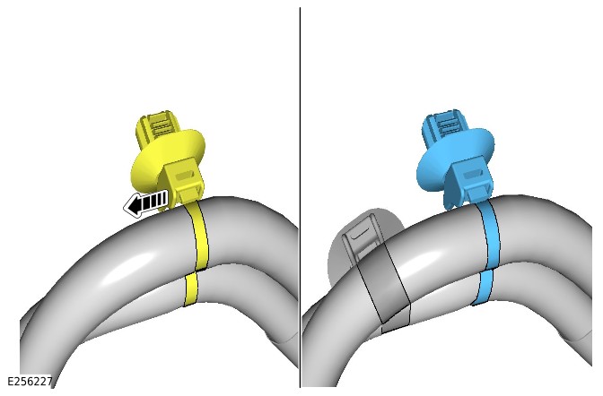
Belt Integrated Starter Generator Inverter to PHEV battery cable (G2431565)
REMOVAL AND INSTALLATION
- 15.10.77
- Belt Integrated Starter Generator Inverter to PHEV battery cable
- 1500 cc, Ingenium PHEV
- 1.70
- USED WITHINS
Removal
WARNINGS:
- It is the responsibility of the Electric Vehicle Authorised Person (EVAP) to make sure they comply with any local legislation for work on High Voltage (HV).
- The approved Personal Protective Equipment (PPE) must be worn where indicated within this procedure and not removed unless indicated within a step. All items of PPE must be checked for signs of damage before each use, if damaged, replacement PPE must be obtained before doing this procedure.
CAUTION:
Make sure all the HV connectors, ground points and locating points are clean and free from foreign material before disconnecting and connecting.
NOTES:
- Permit To Work (PTW) documents must be kept for a minimum of 5 years.
- This procedure contains some variation in the illustrations depending on the vehicle specification, but the essential information is always correct.
- This procedure contains illustrations showing certain components removed to provide extra clarity.
- It is mandated that all technicians involved with the steps in this procedure have read and understood the Electric Vehicle (EV) Safety Rules.Refer to: Electric Vehicle Safety Rules (414-01C Battery, Mounting and Cables - PHEV, Description and Operation).
- Before handling any HV connectors the person(s) completing this procedure must refer to the 'High Voltage Electrical Connector Operation and Inspection' document.Refer to: High Voltage Electrical Connector Operation and Inspection (414-01C Battery, Mounting and Cables - PHEV, General Procedures).
- Raise and support the vehicle on a suitable 2 post lift.Refer to: Jacking and Lifting (100-02 Jacking and Lifting, Description and Operation).
- WARNING:
Jaguar Land Rover (JLR) EVAP trained technicians only.
- WARNING:
JLR Electric Vehicle Competent Person (EVCP) trained technicians only.
- Remove the nut and bolt.
- Reposition the Plug-in Hybrid Electric Vehicle (PHEV) battery heater.
- Use a suitable stand to support the Belt Integrated Starter Generator (BISG) inverter.
- Remove the 7 bolts.
- Lower the support stand to allow access to the top of the BISG inverter.
- Remove the HV cable bracket bolt.
- Disconnect and remove the BISG inverter to PHEV battery cable.
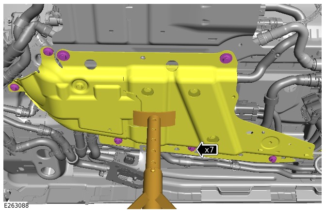
Installation
- Install the BISG inverter to PHEV battery cable to the vehicle.
- Install and tighten the bolt.Torque: 10Nm
- Connect the HV cable to the BISG inverter.
- Raise the BISG inverter.
- Install and tighten the 7 bolts.TorqueM8: 30Nm M10: 60Nm
- Position the PHEV battery heater in the correct location.
- Install and tighten the nut and bolt.Torque: 10Nm
- WARNING:
JLR EVAP trained technicians only.
Rear High Voltage Cable Assembly (G2436012)
REMOVAL AND INSTALLATION
- 15.10.81
- Rear High Voltage Cable Assembly - Renew
- 1500 cc, Ingenium PHEV
- 6.10
- USED WITHINS
Removal
WARNING:
- It is the responsibility of the Electric Vehicle Authorised Person (EVAP) to make sure they comply with any local legislation for work on High Voltage (HV).
- If the vehicle has been powered down, do not power up the vehicle until all the bonding points have been tested.
- The approved Personal Protective Equipment (PPE) must be worn where indicated within this procedure and not removed unless indicated within a step. All items of PPE must be checked for signs of damage before each use, if damaged, replacement PPE must be obtained before doing this procedure.
NOTE:
- All Permit To Work (PTW) documents must be kept for a minimum of 5 years.
- This procedure contains some variation in the illustrations depending on the vehicle specification, but the essential information is always correct.
- This procedure contains illustrations showing certain components removed to provide extra clarity.
- It is mandated that all technicians involved with the steps in this procedure have read and understood the Electric Vehicle (EV) Safety Rules.Refer to: Electric Vehicle Safety Rules (414-01C Battery, Mounting and Cables - PHEV, Description and Operation).
- Before handling any HV connectors the person(s) completing this procedure must refer to the 'High Voltage Electrical Connector Operation and Inspection' document.Refer to: High Voltage Electrical Connector Operation and Inspection (414-01C Battery, Mounting and Cables - PHEV, General Procedures).
- Open the charging socket flap.
- WARNING:
Jaguar Land Rover (JLR) EVAP trained technicians only.
- WARNING:
JLR Electric Vehicle Competent Person (EVCP) trained technicians only.
- Raise and support the vehicle on a suitable 2 post lift.Refer to: Jacking and Lifting (100-02 Jacking and Lifting, Description and Operation).
- Remove the Plug-in Hybrid Electric Vehicle (PHEV) battery.Refer to: PHEV Battery (414-01C Battery, Mounting and Cables - PHEV, Removal and Installation).
- Remove the fuel tank.Refer to: Fuel Tank (310-01D Fuel Tank and Lines - INGENIUM I3 1.5L Petrol, PHEV, Removal and Installation).
- Remove the rear left wheel arch liner.Refer to: Rear Wheel Arch Liner (501-08 Exterior Trim and Ornamentation, Removal and Installation).
- Disconnect the electrical connector from the charging socket.
- Release the wiring harness clip.
Remove the 2 ground cable bolts.
Release the charging socket flap manual opening cable.
- Remove the 2 nuts.
- Release the HV cable from the inner wheel arch.
- Remove the 2 bolts.
- Release the HV cable from the rear outer side member.
- Remove the 3 bolts.
- Release the 2 clips.
- Release the HV cable from the rear inner side member.
- Remove the 2 bolts.
- Release the 2 clips.
- Release the HV cable from the heel board.
Release the HV integrated box to PHEV battery cable clip.
Disconnect the 2 HV cable connectors from the HV integrated box.
Remove the HV cable cover from the Electric Rear Axle Drive (eRAD).
Remove the HV cable bracket bolt from the eRAD.
Disconnect the HV cable from the eRAD.
- Remove the 2 bolts.
- Remove the HV cable bracket.
- Remove the 2 nuts and 2 bolts.
- Release the charging socket assembly.
- Remove the bolt.
- Remove the 3 nuts.
- Release the HV cable from the transmission tunnel and remove it from the vehicle.
- NOTE:
Do not disassemble further if the component is removed for access only.
Release the 5 wiring harness clips.
Release the HV cable clip.
Remove the 4 charging socket bolts.
- Remove the 3 bolts.
- Remove the charging socket bracket.
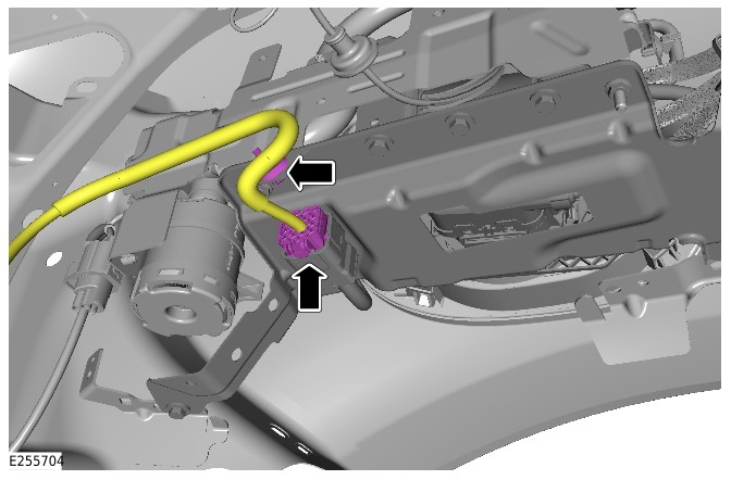
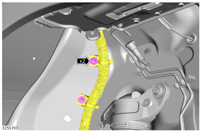
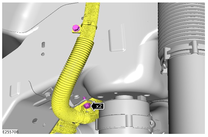
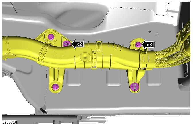
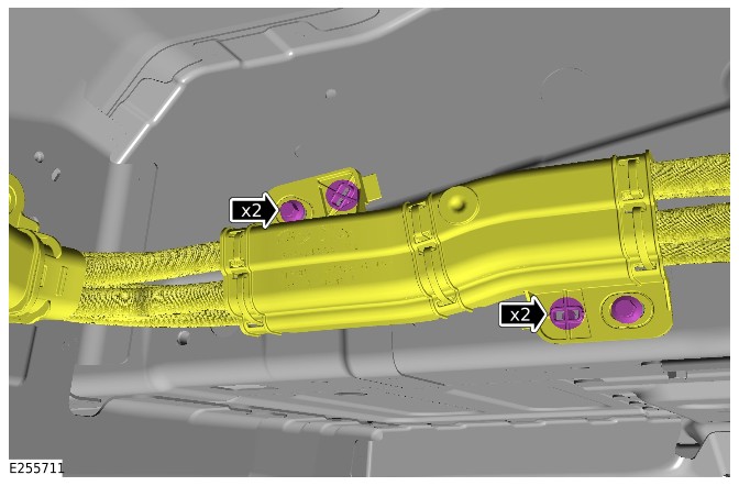
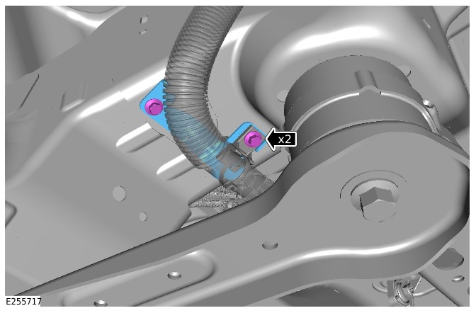
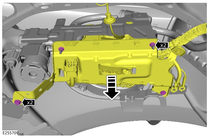
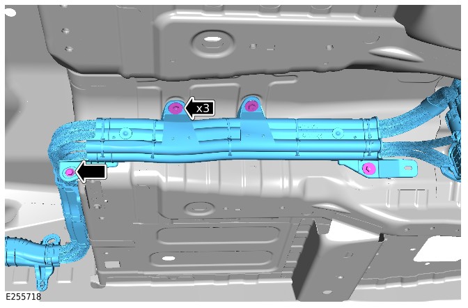
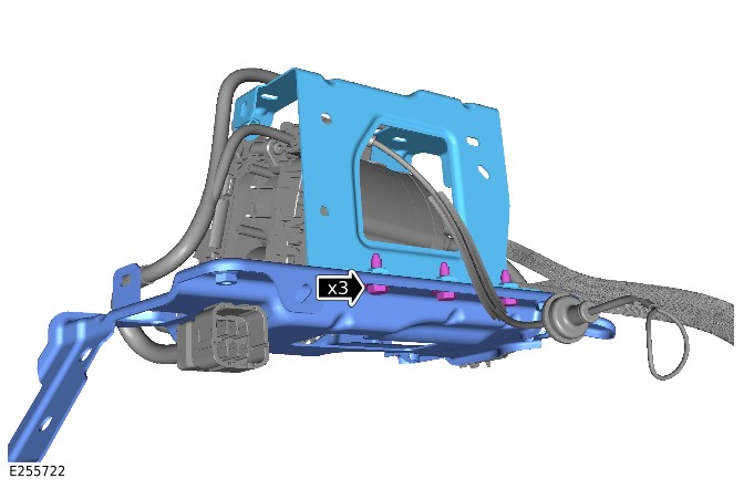
Installation
- CAUTION:
Do not remove the old clip from the HV cable.
NOTE:This step is only required if the HV cable is to be reused.
- Reposition the old clip along the HV cable.
- Install a new clip to the HV cable.
- Install the charging socket bracket.
- Install and tighten the 3 bolts.Torque: 10Nm
- Install and tighten the 4 charging socket bolts.Torque: 5.4Nm
- Install the HV cable clip.
- Install the 5 wiring harness clips.
- Install the HV cable to the vehicle.
- Secure the 2 clips on the heel board.
- Secure the 2 clips on the rear inner side member.
- Install and tighten the 2 heel board bolts.Torque: 10Nm
- Install and tighten the 3 rear inner side member bolts.Torque: 10Nm
- Install and tighten the 3 transmission tunnel nuts.Torque: 5.4Nm
- Install and tighten the transmission tunnel bolt.Torque: 10Nm
- Position the charging socket assembly in the correct location.
- Install and tighten the 2 nuts and 2 bolts.Torque: 10Nm
- Install the HV cable bracket.
- Install and tighten the 2 bolts.Torque: 10Nm
- Connect the HV cable to the eRAD.
- Install the and tighten HV cable bracket bolt to the eRAD.Torque: 4.5Nm
- Install the HV cable cover to the eRAD.
- Connect the 2 HV cable connectors to the HV integrated box.
- Secure the HV integrated box to PHEV battery cable clip.
- Secure the HV cable to the rear outer side member.
- Install and tighten the 2 bolts.Torque: 10Nm
- Install the HV cable clip to the inner wheel arch.
- Install and tighten the 2 nuts.Torque: 5.4Nm
- Install the charging socket flap manual opening cable.
- Install and tighten the 2 ground cable bolts.Torque: 24Nm
- Connect the electrical connector to the charging socket.
- Install the wiring harness clip.
- Install the rear left wheel arch liner.Refer to: Rear Wheel Arch Liner (501-08 Exterior Trim and Ornamentation, Removal and Installation).
- Install the fuel tank.Refer to: Fuel Tank (310-01D Fuel Tank and Lines - INGENIUM I3 1.5L Petrol, PHEV, Removal and Installation).
- Install the PHEV battery.Refer to: PHEV Battery (414-01C Battery, Mounting and Cables - PHEV, Removal and Installation).
- Close the charging socket flap.
Front High Voltage Cable Assembly (G2436013)
REMOVAL AND INSTALLATION
- 15.10.80
- Front HV Cable Assembly
- 1500 cc, Ingenium PHEV
- 2.70
- USED WITHINS
Removal
WARNING:
- It is the responsibility of the Electric Vehicle Authorised Person (EVAP) to make sure they comply with any local legislation for work on High Voltage (HV).
- The approved Personal Protective Equipment (PPE) must be worn where indicated within this procedure and not removed unless indicated within a step. All items of PPE must be checked for signs of damage before each use, if damaged, replacement PPE must be obtained before doing this procedure.
CAUTION:
Make sure all the HV connectors, ground points and locating points are clean and free from foreign material before disconnecting and connecting.
NOTE:
- All Permit To Work (PTW) documents must be kept for a minimum of 5 years.
- This procedure contains some variation in the illustrations depending on the vehicle specification, but the essential information is always correct.
- This procedure contains illustrations showing certain components removed to provide extra clarity.
- It is mandated that all technicians involved with the steps in this procedure have read and understood the Electric Vehicle (EV) Safety Rules.Refer to: Electric Vehicle Safety Rules (414-01C Battery, Mounting and Cables - PHEV, Description and Operation).
- Before handling any HV connectors the person(s) performing this procedure must refer to the 'High Voltage Electrical Connector Operation and Inspection' document.Refer to: High Voltage Electrical Connector Operation and Inspection (414-01C Battery, Mounting and Cables - PHEV, General Procedures).
- Raise and support the vehicle on a suitable 2 post lift.Refer to: Jacking and Lifting (100-02 Jacking and Lifting, Description and Operation).
- Remove the engine undershield.Refer to: Engine Undershield (501-02 Front End Body Panels, Removal and Installation).
- WARNING:
Jaguar Land Rover (JLR) EVAP trained technicians only.
- WARNING:
JLR Electric Vehicle Competent Person (EVCP) trained technicians only.
- Remove the air filter housing.Refer to: Air Filter Housing (303-12C Intake Air Distribution and Filtering - INGENIUM I3 1.5L Petrol, Removal and Installation).
- Remove the nut and bolt.
- Disconnect the HV cable connector from HV heater.
- Remove the bolt.
- Release the HV cable bracket from the HV heater.
- Remove the 2 nuts and 2 bolts.
- Release the HV cable bracket from the transmission.
- Remove the HV cable bracket bolt.
- Disconnect the HV cable connector from the Belt Integrated Starter Generator (BISG).
- Disconnect the HV cable connector from the Air Conditioning (A/C) compressor.
- Remove the 5 bolts.
- Remove the front HV cable connector undershield.
- Remove the 2 nuts.
- Remove the bulkhead heatshield.
Disconnect the 2 HV cable connectors from the HV integrated box.
- Remove the coolant hose bracket bolt.
- Remove the HV cable bracket nut and bolt.
- Release the coolant hose clip.
- Release the HV cable bracket from the transmission tunnel.
- Remove the 2 nuts.
- Release the HV cable bracket from the bulkhead.
- Remove the 2 nuts.
- Remove the bolt.
- Reposition the subframe heatshield away from the front HV cable.
- Release the HV cable bracket from the subframe.
- NOTE:
This step requires the assistance of another technician.
Remove the front HV cable assembly from the vehicle.
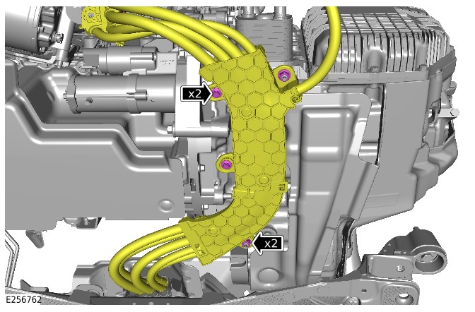
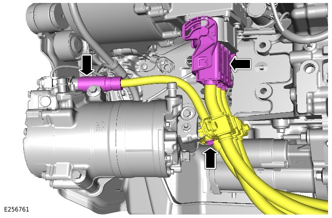
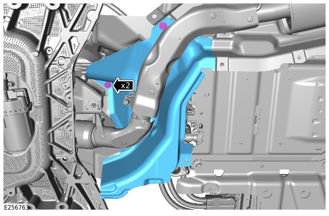
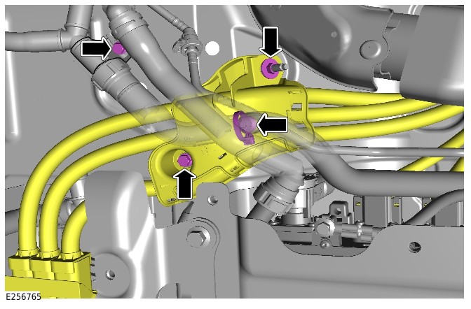
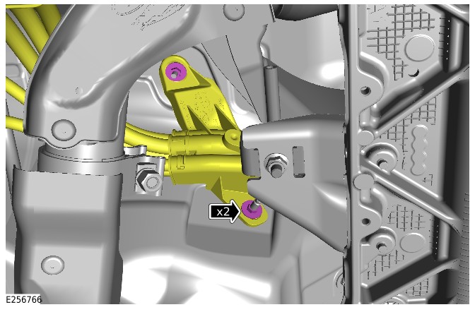
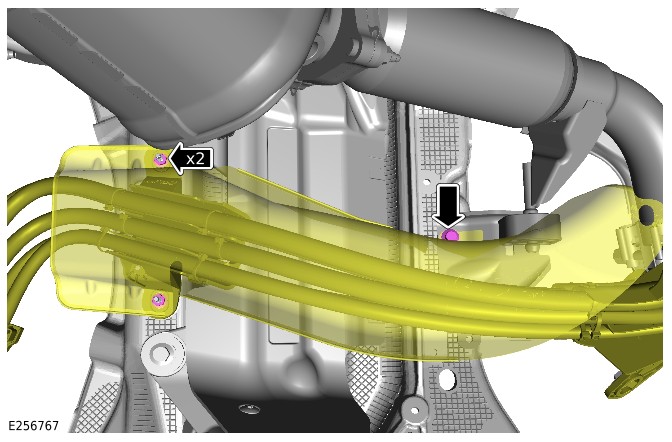
Installation
- NOTE:
This step requires the assistance of another technician.
Install the front HV cable assembly to the vehicle. - Secure the HV cable bracket to the subframe.
- Reposition the subframe heatshield in the correct location.
- Install and tighten the bolt.Torque: 10Nm
- Install and tighten the 2 nuts.Torque: 10Nm
- Secure the HV cable bracket to the bulkhead.
- Install and tighten the 2 nuts.Torque: 5.4Nm
- Secure the HV cable bracket to the transmission tunnel.
- Install and tighten the nut and bolt.Torque: 5.4Nm
- Secure the coolant hose clip.
- Install the coolant hose bracket bolt.Torque: 10Nm
- Connect the 2 HV cable connectors to the HV integrated box.
- Connect the front HV cable connector to the BISG inverter.
- Install the bulkhead heatshield.
- Install and tighten the 2 nuts.Torque: 5.4Nm
- Install the front HV cable connector undershield.
- Install and tighten the 5 bolts.Torque: 30Nm
- Connect the HV electrical connector to the A/C compressor.
- Connect the HV electrical connector to the BISG.
- Install and tighten the HV cable bracket bolt.Torque: 10Nm
- Secure the HV cable bracket to the transmission.
- Install and tighten the 2 nuts and 2 bolts.Torque: 24Nm
- Secure the HV cable bracket to the HV heater.
- Install and tighten the bolt.Torque: 10Nm
- Connect the HV cable connector to the HV heater.
- Install and tighten the nut and bolt.Torque: 10Nm
- Install the air filter housing.Refer to: Air Filter Housing (303-12C Intake Air Distribution and Filtering - INGENIUM I3 1.5L Petrol, Removal and Installation).
- WARNING:
JLR EVAP trained technicians only.
- Install the engine undershield.Refer to: Engine Undershield (501-02 Front End Body Panels, Removal and Installation).
Auxiliary Battery (G2784312)
REMOVAL AND INSTALLATION
- 86.15.03
- auxiliary battery - renew
- All Derivatives
- 0.50
- USED WITHINS
Removal
NOTE:
- This procedure contains some variation in the illustrations depending on the vehicle specification, but the essential information is always correct.
- This procedure contains illustrations with components removed to provide extra clarity.
- This procedure contains illustrations for right hand drive vehicles, left hand drive vehicles are similar.
- Disconnect the 12V system.Refer to: 12V System Disconnect (414-00 Battery and Charging System - General Information, General Procedures).
- Remove the cowl panel.Refer to: Cowl Panel (501-02 Front End Body Panels, Removal and Installation).
- Remove the nut.
- Release the auxiliary junction box.
- Release the auxiliary battery terminal access cover.
- Disconnect the auxiliary battery positive cable.
- Disconnect the breather pipe.
- Disconnect the auxiliary battery ground cable.
- Remove the nut.
- Remove the auxiliary battery clamp.
Installation
- Install the battery heat shield.
- Install the auxiliary battery.
- Install the auxiliary battery clamp.
- Install and tighten the nut.Torque: 10Nm
- Connect the breather pipe.
- Connect the auxiliary battery ground cable.Torque: 6Nm
- Connect the auxiliary battery positive cable.Torque: 6Nm
- Install the auxiliary battery terminal access cover.
- Install the auxiliary battery junction box.
- Install and tighten the nut.Torque: 10Nm
- Install the cowl panel.Refer to: Cowl Panel (501-02 Front End Body Panels, Removal and Installation).
- Connect the 12V system.Refer to: 12V System Disconnect (414-00 Battery and Charging System - General Information, General Procedures).
High Voltage Coolant Heater (G3262201)
REMOVAL AND INSTALLATION
- 15.10.49
- High Voltage Interior Heater - Renew
- 1500 cc, Ingenium PHEV
- 2.80
- USED WITHINS
General Equipment
| Equipment name |
|---|
| Fluke 1507 Insulation Tester |
Removal
WARNING:
- It is the responsibility of the Electric Vehicle Authorised Person (EVAP) to make sure they comply with any local legislation for work on High Voltage (HV).
- The approved Personal Protective Equipment (PPE) must be worn where indicated within this procedure and not removed unless indicated within a step. All items of PPE must be checked for signs of damage before each use, if damaged, replacement PPE must be obtained before doing this procedure.
- If the vehicle has been powered down, do not power up the vehicle until all the bonding points have been tested.
CAUTION:
- Make sure all the HV connectors, ground points and locating points are clean and free from foreign material before disconnecting and connecting.
- Before disconnecting any components, make sure the area is clean and free from foreign material. When disconnected all openings must be sealed.
NOTE:
- Permit To Work (PTW) documents must be kept for a minimum of 5 years.
- This procedure contains some variation in the illustrations depending on the vehicle specification, but the essential information is always correct.
- This procedure contains illustrations showing certain components removed to provide extra clarity.
- It is mandated that all technicians involved with the steps in this procedure have read and understood the Electric Vehicle (EV) Safety Rules.Refer to: Electric Vehicle Safety Rules (414-01C Battery, Mounting and Cables - PHEV, Description and Operation).
- Before handling any HV connectors the person(s) completing this procedure must refer to the 'High Voltage Electrical Connector Operation and Inspection' document.Refer to: High Voltage Electrical Connector Operation and Inspection (414-01C Battery, Mounting and Cables - PHEV, General Procedures).
- WARNING:
Jaguar Land Rover Jaguar Land Rover (JLR) EVAP trained technicians only.
- WARNING:
JLR Electric Vehicle Competent Person (EVCP) trained technicians only.
- Raise and support the vehicle on a suitable 2 post lift.Refer to: Jacking and Lifting (100-02 Jacking and Lifting, Description and Operation).
- Drain the engine and Electric Rear Axle Drive (eRAD) cooling system.Refer to: Engine and eRAD Cooling System Draining and Vacuum filling (303-03C Engine Cooling - INGENIUM I3 1.5L Petrol, General Procedures).
- Remove the engine undershield.Refer to: Engine Undershield (501-02 Front End Body Panels, Removal and Installation).
- Remove the air filter housing.Refer to: Air Filter Housing (303-12C Intake Air Distribution and Filtering - INGENIUM I3 1.5L Petrol, Removal and Installation).
- Remove the ground cable nut.
- Release the 2 wiring harness clips.
- Disconnect the HV cable connector.
- Remove the nut and bolt.
- Remove the bolt.
- Release the HV cable.
- Remove the 2 nuts and bolts.
- Remove the HV coolant heater.
- NOTE:
Do not disassemble further if the component is removed for access only.
- Remove the 4 bolts.
- Remove the bracket.
- Release the 2 coolant hose clips.
- Remove the 2 coolant hoses.
Installation
- Install the 2 coolant hoses.
- Install the 2 coolant hose clamps.
- Install the bracket.
- Install and tighten the 4 bolts.Torque: 8Nm
- Install the HV coolant heater.
- Install and tighten the 2 nuts and 2 bolts.Torque: 10Nm
- Connect the ground cable.Torque: 8Nm
- Install the wiring harness to the 2 clips.
- Use General Equipment Fluke 1507 Insulation Tester to complete the EV bonding test.General Equipment: Fluke 1507 Insulation Tester
- A) Connect the probe to the casing of HV coolant heater.
- B) Connect the probe to the ground point.
- The bonding test can only be passed if a reading of under 50 milliohms is achieved. Any measurement above this must be investigated.
- Reposition the HV cable in the correct location.
- Install and tighten the bolt.Torque: 10Nm
- Connect the HV cable connector.
- Install and tighten the nut and bolt.Torque: 10Nm
- Connect the electrical connector.
- Connect the 2 coolant hoses.
- Remove the 2 hose clamps.
- Install the air filter housing.Refer to: Air Filter Housing (303-12C Intake Air Distribution and Filtering - INGENIUM I3 1.5L Petrol, Removal and Installation).
- Install the engine undershield.Refer to: Engine Undershield (501-02 Front End Body Panels, Removal and Installation).
- WARNING:
Jaguar Land Rover JLR EVAP trained technicians only.
- Vacuum fill the engine and eRAD cooling system.Refer to: Engine and eRAD Cooling System Draining and Vacuum filling (303-03C Engine Cooling - INGENIUM I3 1.5L Petrol, General Procedures).
PHEV Battery Coolant Heater (G3262299)
REMOVAL AND INSTALLATION
- 15.10.56
- PHEV Battery Coolant Heater - Renew
- 1500 cc, Ingenium PHEV
- 1.60
- USED WITHINS
Removal
CAUTION:
Before disconnecting any components, make sure the area is clean and free from foreign material. When disconnected all openings must be sealed.
NOTE:
- This procedure contains some variation in the illustrations depending on the vehicle specification, but the essential information is always correct.
- This procedure contains illustrations showing certain components removed to provide extra clarity.
- It is mandated that all technicians involved with the steps in this procedure have read and understood the electric vehicle safety rules.Refer to: Electric Vehicle Safety Rules (414-01C Battery, Mounting and Cables - PHEV, Description and Operation).
- WARNING:
Jaguar Land Rover (JLR) Electric Vehicle Competent Person (EVCP) trained technicians only.
- Raise and support the vehicle on a suitable 2 post lift.Refer to: Jacking and Lifting (100-02 Jacking and Lifting, Description and Operation).
- Drain the Plug-in Hybrid Electric Vehicle (PHEV) battery cooling system.Refer to: PHEV Battery Cooling System Draining and Vacuum Filling (414-01C Battery, Mounting and Cables - PHEV, General Procedures).
- WARNING:
Be prepared to collect escaping coolant.
- Release the 2 coolant hose clips.
- Disconnect the 2 coolant hoses from the PHEV battery coolant heater.
Disconnect the electrical connector from the PHEV battery coolant heater.
- Remove the nut and bolt.
- Remove the clip.
- Remove the PHEV battery coolant heater assembly from the vehicle.
- NOTE:
Do not disassemble further if the component is removed for access only.
- Remove the 3 nuts.
- Remove the PHEV battery coolant heater from the bracket.
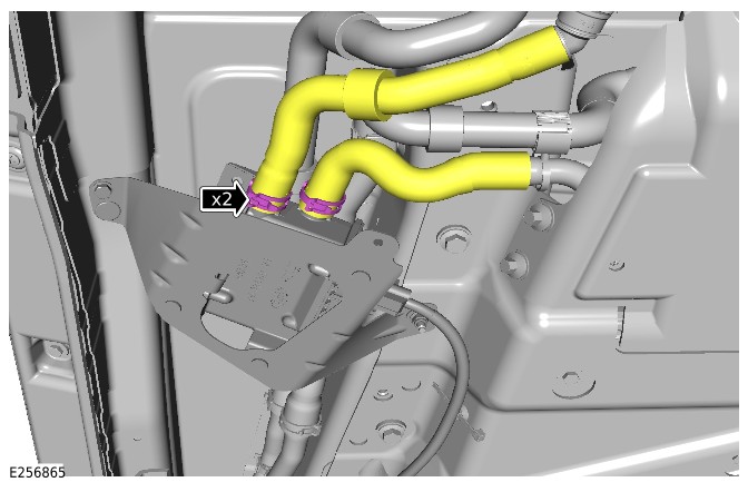
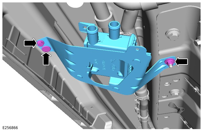
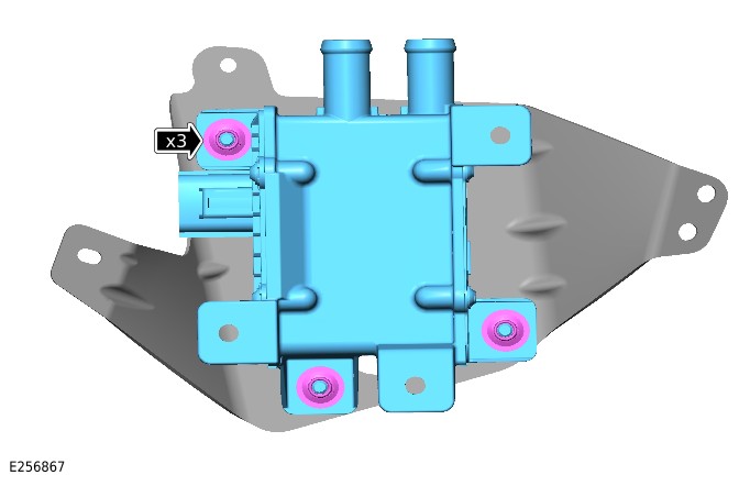
Installation
- Install the PHEV battery coolant heater to the bracket.
- Install and tighten the 3 nuts.Torque: 10Nm
- Install the PHEV battery coolant heater assembly to the vehicle.
- Install and tighten the nut and bolt.Torque: 10Nm
- Install the clip.
- Connect the electrical connector to the PHEV battery coolant heater.
- Connect the 2 coolant hoses to the PHEV battery coolant heater.
- Secure the 2 coolant hose clips.
- Refill and bleed the PHEV battery cooling system.Refer to: PHEV Battery Cooling System Draining and Vacuum Filling (414-01C Battery, Mounting and Cables - PHEV, General Procedures).
Coolant Diverter Valve (G4758912)
REMOVAL AND INSTALLATION
- 15.20.20
- Diverter Valve - PHEV Battery Cooling System - Renew
- 1500 cc, Ingenium PHEV
- 1.50
- USED WITHINS
Removal
NOTES:
- This procedure contains some variation in the illustrations depending on the vehicle specification, but the essential information is always correct.
- This procedure contains illustrations showing certain components removed to provide extra clarity.
- Disconnect the startup battery ground cable.Refer to: 12V System Disconnect (414-00 Battery and Charging System - General Information, General Procedures).
- Raise and support the vehicle on a suitable 2 post lift.Refer to: Jacking and Lifting (100-02 Jacking and Lifting, Description and Operation).
- Partially drain the cooling system.Refer to: Engine Cooling System Draining and Vacuum Filling - Vehicles With: PHEV (303-03C Engine Cooling - INGENIUM I3 1.5L Petrol, General Procedures).
- Remove the front right wheel arch liner.Refer to: Front Wheel Arch Liner (501-02 Front End Body Panels, Removal and Installation).
Release the clip and position the hose assembly to one side.
Release the 4 screws.
Reposition the coolant diverter valve assembly to gain access to the hoses and electrical connection.
- CAUTION:
Be prepared to collect escaping coolant.
NOTE:Coolant diverter valve mounting bracket shown removed for clarity.
Release the 3 hoses and position to one side.
- Release the electrical connector and remove the coolant diverter valve.
- CAUTION:
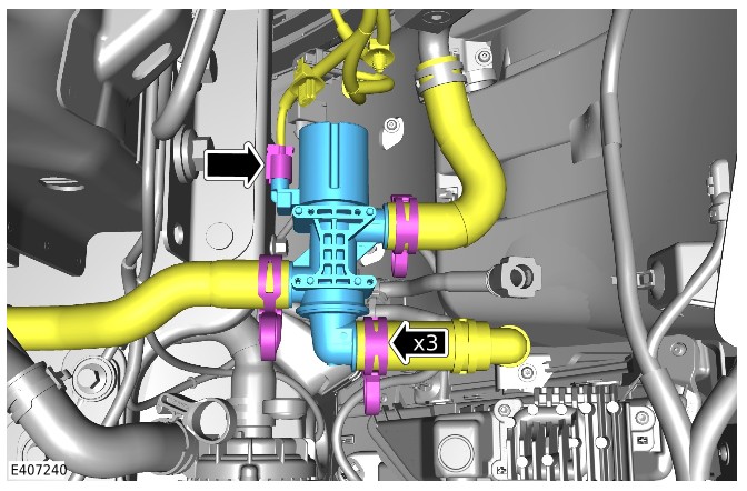
Installation
- NOTE:
Coolant diverter valve mounting bracket shown removed for clarity.
- Install the coolant diverter valve and connect the electrical connector.
- Connect the 3 hoses.
Reposition the coolant diverter valve assembly.
- Install the front right wheel arch liner.Refer to: Front Wheel Arch Liner (501-02 Front End Body Panels, Removal and Installation).
- Connect the startup battery ground cable.Refer to: 12V System Disconnect (414-00 Battery and Charging System - General Information, General Procedures).
- Vacuum fill the cooling system.Refer to: Engine Cooling System Draining and Vacuum Filling - Vehicles With: PHEV (303-03C Engine Cooling - INGENIUM I3 1.5L Petrol, General Procedures).
PHEV Battery Coolant Pump (G4773625)
REMOVAL AND INSTALLATION
- 15.11.44
- High Voltage Battery Coolant Pump - Renew
- 1500 cc, Ingenium PHEV
- 0.80
- USED WITHINS
Removal
WARNING:
Injury such as scalding could be caused by escaping steam or coolant. Make sure the vehicle cooling system is cool prior to carrying out this procedure.
NOTES:
- This procedure contains some variation in the illustrations depending on the vehicle specification, but the essential information is always correct.
- This procedure contains illustrations showing certain components removed to provide extra clarity.
- Raise and support the vehicle on a suitable 2 post lift.Refer to: Jacking and Lifting (100-02 Jacking and Lifting, Description and Operation).
- Remove the 5 wheel nuts.
- Remove the front left wheel.
- Remove the front left wheel arch liner.Refer to: Front Wheel Arch Liner (501-02 Front End Body Panels, Removal and Installation).
- WARNING:
Be prepared to collect escaping coolant.
- Clamp the 2 coolant hoses.
- Remove the 2 coolant hose clamps.
- Disconnect the 2 coolant hoses.
- Disconnect the electrical connector.
- Remove the coolant pump from the 3 securing tabs.
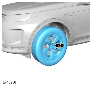
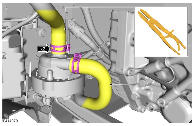
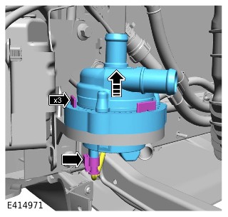
Installation
- Install the coolant pump to the 3 securing tabs.
- Connect the electrical connector.
- Install the 2 coolant hoses.
- Install the 2 coolant hose clamps.
- Remove the 2 hose clamp tools.
- Install the front left wheel arch liner.Refer to: Front Wheel Arch Liner (501-02 Front End Body Panels, Removal and Installation).
- Install the front left wheel.Refer to: Wheel and Tire (204-04 Wheels and Tires, Removal and Installation).
- Check and top up the coolant if required.
Generator and Regulator - INGENIUM I3 1.5L Petrol/INGENIUM I4 2.0L Petrol (G2320427)
SPECIFICATIONS
Torque Specifications
| Component Torque Location |
|---|
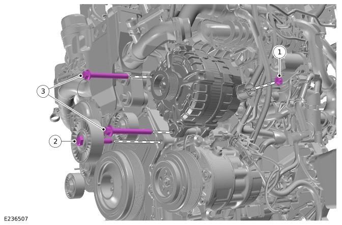
|
| Description | Nm | lb-ft | lb-in | |
|---|---|---|---|---|
| 1 | Battery positive cable M8 nut | 12 | 9 | - |
| 2 | Idler pulley bolt | 47.5 | 35 | - |
| 3 | Generator M10 x 90 bolt | 47.5 | 35 | - |
| Component Torque Location |
|---|
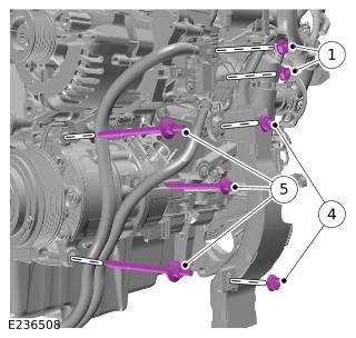
|
| Description | Nm | lb-ft | lb-in | |
|---|---|---|---|---|
| 1 | Battery positive cable M8 nut | 12 | 9 | - |
| 4 | Battery positive cable bracket M6 nut | 9 | - | 80 |
| 5 | Air conditioning (A/C) compressor M8 x 97.5 bolt | 25 | 18 | - |
| Component Torque Location |
|---|
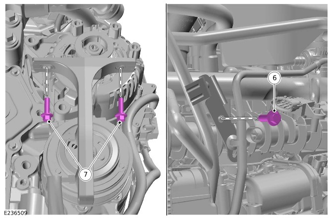
|
| Description | Nm | lb-ft | lb-in | |
|---|---|---|---|---|
| 6 | Oil level gauge M6 x 20 bolt | 7 | - | 62 |
| 7 | Battery positive cable bracket M6 x 20 bolt | 9 | - | 80 |
| Component Torque Location |
|---|
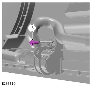
|
| Description | Nm | lb-ft | lb-in | |
|---|---|---|---|---|
| 8 | Charge air coolant pump M6 x 20 bolt | 9 | - | 80 |
Generator and Regulator - INGENIUM I3 1.5L Petrol/INGENIUM I4 2.0L Petrol
Generator - Vehicles Without: MHEV (G2361761)
DESCRIPTION AND OPERATION
COMPONENT LOCATION
Component Location - 1 of 1
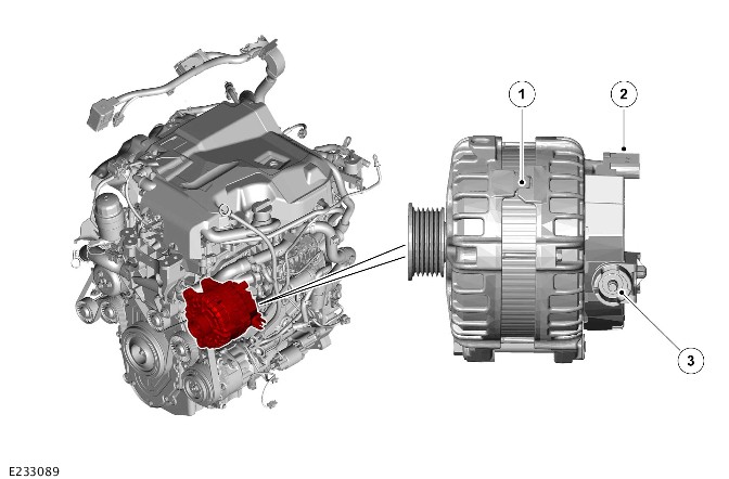
| Item | Description |
|---|---|
| 1 | Generator |
| 2 | Electrical connector - Body Control Module/Gateway Module (BCM/GWM) |
| 3 | Electrical connector - Battery Junction Box (BJB) |
OVERVIEW
When the engine is running, the generator produces an Alternating Current (AC) which is converted to a Direct Current (DC) internally. The output voltage from the generator is controlled by the regulator which is located inside the generator. The output voltage is supplied to the positive terminal of the startup battery via the Battery Junction Box (BJB).
For additional information, refer to: Battery and Cables (414-01 Battery, Mounting and Cables - Vehicles With: Non-Electric Vehicles, Description and Operation).
DESCRIPTION
Generator
The generator is installed on the front right of the engine. The generator produces electrical power for the electrical system and charges the startup battery. The generator is driven by the accessory drive belt. The Body Control Module/Gateway Module (BCM/GWM) controls the generator via the Local Interconnect Network (LIN).
When the communication between the generator and BCM/GWM is lost, the generator generates at a default voltage. The default voltage is 13.5V or 13.8V (depending on the specific generator variant). In order to instigate the default mode, the generator needs to be initially spun above 3,000 rpm.
Battery Monitoring System Control Module
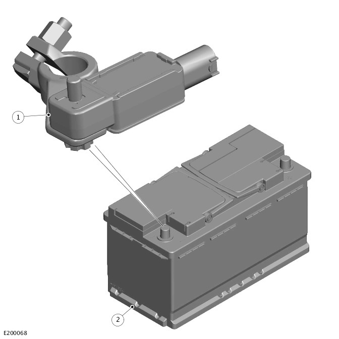
The Battery Monitoring System (BMS) control module is located on the negative terminal of the startup battery. The BMS control module monitors the temperature, current, voltage, current drain and charge state of the startup battery. The BMS control module is connected with the Body Control Module/Gateway Module (BCM/GWM) via the Local Interconnect Network (LIN). The BMS control module constantly receives information from the BCM/GWM regarding the vehicle state and electrical loading. The BMS control module contains software maps that provide a mathematical model of the startup battery conditions.
For additional information, refer to: Battery and Cables (414-01 Battery, Mounting and Cables - Vehicles With: Non-Electric Vehicles, Description and Operation).
OPERATION
The charging system consists of a generator, a Battery Monitoring System (BMS) control module and a Body Control Module/Gateway Module (BCM/GWM). The generator generates electrical power for the vehicle electrical system and maintains the startup battery in a charged state. The rate of charge for the startup battery is controlled by the BCM/GWM.
Both the generator and BMS control module are connected to the BCM/GWM via the Local Interconnect Network (LIN). The BCM/GWM receives information from the BMS control module regarding startup battery conditions. The BCM/GWM sets the target voltage according to the information from the BMS control module. The charging voltage range is 12.3V to 14.8V.
The LIN is also used to communicate a mechanical failure, or fault in the wiring harness and connections between the generator and BCM/GWM. A Diagnostic Trouble Code (DTC) is stored in the BCM/GWM. When necessary, the charge warning indicator is illuminated in the Instrument Cluster (IC) after a short delay.
During engine starting, the charge warning indicator is illuminated in the IC in Power Mode 6 and below. The charge warning indicator is extinguished in Power Mode 7 when the BCM/GWM detects a generator output voltage.
For additional information, refer to: Battery and Cables (414-01 Battery, Mounting and Cables - Vehicles With: Non-Electric Vehicles, Description and Operation).
Smart Charging System
The smart regenerative charging system converts the kinetic energy of the vehicle into electric energy without additional fuel.
The smart regenerative feature operates within certain environmental constraints. This makes sure that the feature delivers the greatest benefit possible, whilst maintaining system integrity.
The regenerated electric energy is captured by charging the startup battery above the target level. The electrical systems uses the electric energy at a later stage. This could be when the engine is switched off during a stop-phase, but can also be when the generator operates in a less efficient mode.
The state charge of the startup battery is corrected both up and down. This allows the system to achieve the most appropriate level to maximize the benefit of the smart regenerative charging feature. When the Body Control Module/Gateway Module (BCM/GWM) decides there is recoverable energy available, then the generator charge set-point is overridden.
The purpose of this system is so the generator does not constantly charge the startup battery in circumstances such as:
- When there is high torque load on the engine.
- When the vehicle is on a long motorway journey.
The BCM/GWM allows the generator to put more voltage than normal in the startup battery. When the driver puts a high torque load on the engine, the BCM/GWM does a check to see what load is on the electrical system. If the electrical load is within parameters, the BCM/GWM decreases the quantity of charge it puts into the startup battery. To do this, the BCM/GWM decreases the voltage and rate of charge. The BCM/GWM can also stop charging the battery. These actions decrease:
- The load on the engine
- Fuel consumption
- Emissions.
When the torque load on the engine decreases, the BCM/GWM increases the quantity of charge that goes into the startup battery.
The BCM/GWM constantly monitors all active electrical loads and changes the output of the generator to match. The operation of the system is not visible to the driver.
Diagnostics
The Body Control Module/Gateway Module (BCM/GWM) and Battery Monitoring System (BMS) control module record any Diagnostic Trouble Codes (DTCs) and related data. The DTCs and related data are read using the Jaguar Land Rover (JLR) approved diagnostic equipment.
The JLR approved diagnostic equipment enables certain components to be activated and also read live data.
CONTROL DIAGRAM
Control Diagram - 1 of 1
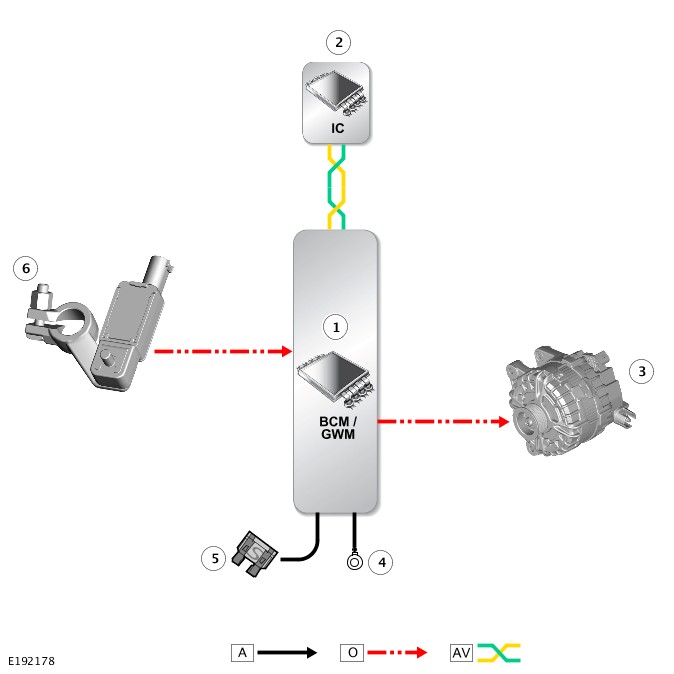
A = Hardwired: O = Local Interconnect Network (LIN): AV = High Speed (HS) Controller Area Network (CAN) comfort systems bus.
| Item | Description |
|---|---|
| 1 | Body Control Module/Gateway Module (BCM/GWM) |
| 2 | Instrument Cluster (IC) |
| 3 | Generator |
| 4 | Ground |
| 5 | Power supply |
| 6 | Battery Monitoring System (BMS) control module |
Belt Integrated Starter Generator - Vehicles With: MHEV (G2313265)
DESCRIPTION AND OPERATION
Component Location
Component Location - 1 of 2 - INGENIUM I3 1.5L Petrol
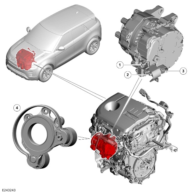
| Item | Description |
|---|---|
| 1 | MHEV battery negative connection |
| 2 | MHEV battery positive connection |
| 3 | Electric connector |
| 4 | Belt Integrated Starter Generator (BISG) drive belt tensioner |
Component Location - 2 of 2 - INGENIUM I4 2.0L Petrol
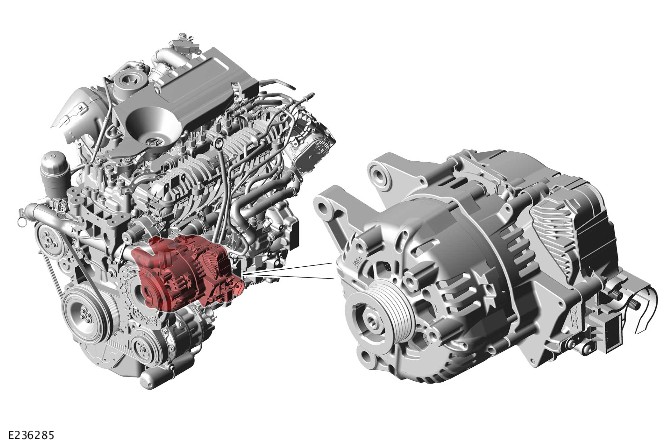
Overview
The Belt Integrated Starter Generator (BISG) is used as a generator on the Mild Hybrid Electric Vehicle (MHEV). The output of the generator is 48V. The output provides 48V for the Direct Current to Direct Current (DC/DC) converter for use on the vehicle systems. The output also charges the MHEV battery.
For additional information, refer to: Belt Integrated Starter Generator - Vehicles With: MHEV (414-03 Battery Charging, Description and Operation).
The BISG is used as a starter motor on the MHEV. The BISG provides a virtually silent engine crank.
NOTE:
The conventional starter motor always does the first crank, regardless of the ambient temperature.
- Starting System - INGENIUM I3 1.5L Petrol.
- For additional information, refer to: Starting System (303-06C Starting System - INGENIUM I3 1.5L Petrol, Vehicles With: MHEV, Description and Operation).
- For additional information, refer to: Belt Integrated Starter Generator - Vehicles With: MHEV (414-03 Battery Charging, Description and Operation).
- Starting System - INGENIUM I4 2.0L Petrol.
- For additional information, refer to: Starting System - [+] MHEV (303-06B, Description and Operation).
- For additional information, refer to: Belt Integrated Starter Generator - Vehicles With: MHEV (414-03 Battery Charging, Description and Operation).
- The Belt Integrated Starter Generator (BISG) also assists the engine to reduce fuel consumption. The BISG is driven by 48V from the MHEV battery.
- For additional information, refer to: Belt Integrated Starter Generator - Vehicles With: MHEV (414-03 Battery Charging, Description and Operation).
- Direct Current to Direct Current (DC/DC) converter.
- For additional information, refer to: Direct Current to Direct Current Converter - Vehicles With: MHEV (414-03 Battery Charging, Description and Operation).
- MHEV battery.
- For additional information, refer to: MHEV Battery and Cables (414-01B, Description and Operation).
Belt Integrated Starter Generator - RBoM - INGENIUM I3 1.5L Petrol, PHEV (G4463135)
Part(s)
All vehicles
| Name | Quantity | Part Number | ||||||||||
|---|---|---|---|---|---|---|---|---|---|---|---|---|
| Air conditioning compressor inlet pipe O-ring seal(s) | 1 | LR117495 | ||||||||||
| Air conditioning compressor outlet pipe O-ring seal(s) | 1 | LR117494 | ||||||||||
| Engine mount insulator bracket bolt(s) | 2 | LR114980 | ||||||||||
| Engine mount insulator bush bracket bolt(s) | 1 | LR114981 | ||||||||||
| Generator (Main Component) | 1 |
| ||||||||||
| Oil level tube O-ring seal | 2 | LR139073 |
Special Tool(s)
All vehicles
| 12 Volt Battery Lock-offJLR-415-133 | |
| Accessory Drive Belt Tensioner Locking ToolJLR-303-1669 |  |
| Break Out Box - High Voltage (HV) Auxiliary Circuit ConnectorJLR-415-136 | |
| Break Out Box Safety Check Connector – High Voltage (HV) Auxiliary Circuit ConnectorJLR-415-137 | |
| Crank Rotation ToolJLR-303-1656 |  |
| Installer, Front End Accessory Drive (FEAD) BeltJLR-303-1640 | 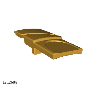 |
| Lock Off - High Voltage (HV) Auxiliary CircuitJLR-415-115 | |
| Main High Voltage (HV) Connector Lock-offJLR-415-114 | |
| Main High Voltage connector break-out boxJLR-415-134 | |
| Main High Voltage connector break-out box safety check connectorJLR-415-135 | |
| Master Service Disconnect (MSD) Lock-off (CATL Battery)JLR-415-116 | |
| Master Service Disconnect (MSD) Lock-off (SDI Battery)JLR-415-117 | |
| Measurement Probes (GS38)JLR-415-092 | |
| Protective StickerJLR-415-024 | |
| Universal Cable Lock-offJLR-415-132 | |
| Voltage IndicatorC.A 773 | |
| Voltage Tester Proving UnitPU690 | |
| Adaptor, Cooling System Vacuum Refill KitJLR-303-1634 | |
| Coolant System Vacuum Refill KitHU-919 | |
Plug in hybrid electric vehicles only
| 12 Volt Battery Lock-offJLR-415-133 | |
| Universal Cable Lock-offJLR-415-132 | |
Repair
Belt Integrated Starter Generator - INGENIUM I3 1.5L Petrol, Vehicles With: PHEV (414-02B REMOVAL AND INSTALLATION G2408971)
Published: 07-Dec-2020
2022.0 New Range Rover Evoque (LZ), 414-02B
Generator and Regulator - INGENIUM I3 1.5L Petrol/INGENIUM I4 2.0L Petrol
Belt Integrated Starter Generator - INGENIUM I3 1.5L Petrol, Vehicles With: PHEV (G2408971)
REMOVAL AND INSTALLATION
- 86.60.30
- Belt Integrated Starter Generator - Renew
- 1500 cc, Ingenium PHEV
- 4.00
- USED WITHINS
- 86.60.30.32
- Belt Integrated Starter Generator - Renew - MHEV Vehicles
- 1500 cc, INGENIUM PETROL
- 4.70
- USED WITHINS
General Equipment
| Equipment name |
|---|
| Jaguar Land Rover approved diagnostic equipment |
Part(s)
| Step | Part name | Quantity |
|---|---|---|
| Installation Step 6 | Oil level gauge O-ring seal | 2 |
Removal
WARNING:
This procedure can only be completed after the vehicle has been powered down by an approved person.
CAUTIONS:
- If the High Voltage (HV) Belt Integrated Starter Generator (BISG) motor or the HV BISG inverter is replaced, the procedure for calibrating the motor to the HV BISG inverter must be followed.
- The calibration procedure must be followed accurately to avoid engine malfunction and dangerous vehicle behavior.
NOTE:
- This procedure contains some variation in the illustrations depending on the vehicle specification, but the essential information is always correct.
- This procedure contains illustrations showing certain components removed to provide extra clarity.
- Raise and support the vehicle on a suitable 2 post lift.Refer to: Jacking and Lifting (100-02 Jacking and Lifting, Description and Operation).
- Before handling any HV connectors the person(s) completing this procedure must refer to the 'High Voltage Electrical Connector Operation and Inspection' document.Refer to: High Voltage Electrical Connector Operation and Inspection (414-01C Battery, Mounting and Cables - PHEV, General Procedures).
- CAUTION:
Jaguar Land Rover (JLR) Electric Vehicle Authorised Person (EVAP) trained technicians only.
- Evacuate the Air Conditioning (A/C) system.Refer to: Air Conditioning System Recovery, Evacuation and Charging (412-00 Climate Control System - General Information, General Procedures).
- Partially drain the cooling system.Refer to: Engine Cooling System Draining and Vacuum Filling - Vehicles With: PHEV (303-03C Engine Cooling - INGENIUM I3 1.5L Petrol, General Procedures).
- Remove the BISG belt.Refer to: Belt Integrated Starter Generator Belt (303-05D Accessory Drive - INGENIUM I3 1.5L Petrol, Vehicles With: PHEV, Removal and Installation).
- Remove the HV A/C compressor.Refer to: Air Conditioning Compressor - INGENIUM I3 1.5L Petrol, PHEV (412-01 Climate Control, Removal and Installation).
- Remove the powertrain lower support insulator.Refer to: Powertrain Lower Support Insulator (303-01C Engine - INGENIUM I3 1.5L Petrol, Removal and Installation).
- Remove the cover.
- Remove the bolt.
- Remove the BISG belt idler pulley.
- Release the clip.
- Remove the 3 bolts.
- Remove the A/C compressor bracket.
- Remove the 3 bolts.
- Remove the engine oil level gauge.
- Disconnect the oil level gauge lower pipe.
- Remove and discard the 2 O-ring seals.
Disconnect the HV electrical connector from the BISG.
- Disconnect the 2 coolant hoses from the BISG.
- Disconnect the breather pipe from the BISG.
- Disconnect the electrical connector from the BISG.
Make sure no damage is caused to the vacuum pipe connector when removing the BISG.
- NOTE:
This step requires the aid of another technician.
Use a suitable tool to reposition the engine assembly to get access to the BISG.
- NOTE:
This step requires the aid of another technician.
- Remove the 2 bolts.
- Remove the BISG.
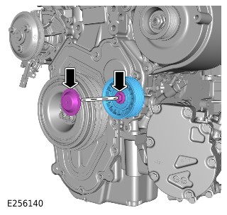
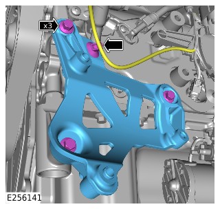
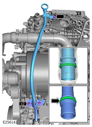
Installation
- NOTE:
This step requires the aid of another technician.
- Install the BISG.
- Install and tighten the 2 bolts.Torque: 47.5Nm
- Connect the 2 coolant hoses to the BISG.
- Connect the breather pipe to the BISG.
- Connect the electrical connector to the BISG.
- Connect the HV electrical connector to the BISG.
- Install 2 new O-ring seals.
- Connect the oil level gauge lower pipe to the upper pipe.Renew Part: Oil level gauge O-ring seal Quantity: 2.
- Install the oil level gauge.
- Install and tighten the 3 bolts.Torque: 7Nm
- Install the A/C compressor bracket.
- Install and tighten the 3 bolts.Torque: 25Nm
- Install the wiring harness clip.
- Install the BISG belt idler pulley.
- Install and tighten the bolt.Torque: 47.5Nm
- Install the cover.
- Install the powertrain lower support insulator.Refer to: Powertrain Lower Support Insulator (303-01C Engine - INGENIUM I3 1.5L Petrol, Removal and Installation).
- Install the HV A/C compressor.Refer to: Air Conditioning Compressor - INGENIUM I3 1.5L Petrol, PHEV (412-01 Climate Control, Removal and Installation).
- Install the BISG belt.Refer to: Belt Integrated Starter Generator Belt (303-05D Accessory Drive - INGENIUM I3 1.5L Petrol, Vehicles With: PHEV, Removal and Installation).
- Fill and bleed the cooling system.Refer to: Engine Cooling System Draining and Vacuum Filling - Vehicles With: PHEV (303-03C Engine Cooling - INGENIUM I3 1.5L Petrol, General Procedures).
- Charge the A/C system.Refer to: Air Conditioning System Recovery, Evacuation and Charging (412-00 Climate Control System - General Information, General Procedures).
- If a new BISG has been installed, use the Jaguar Land Rover (JLR) approved diagnostic equipment to configure the BISG to the BISG inverter.General Equipment: Jaguar Land Rover approved diagnostic equipment
Belt Integrated Starter Generator System Cleaning (G3339785)
GENERAL PROCEDURES
- 86.60.35
- Belt Integrated Starter Generator System - Cleaning
- 1500 cc, INGENIUM PETROL
- 4.70
- USED WITHINS
Part(s)
| Step | Part name | Part Number | Quantity |
|---|---|---|---|
| Check Step 7 | Belt integrated starter generator belt | LR135159 | 1 |
Check
- Remove the Belt Integrated Starter Generator (BISG)Refer to: Belt Integrated Starter Generator - INGENIUM I6 3.0L Diesel, [+] MHEV (414-02 Generator and Regulator - INGENIUM I6 3.0L Diesel, [+] MHEV, Removal and Installation).
- CAUTION:
Do not clean the component with any liquids or solvents as this could cause damage to the electrical components
Using a suitable cloth or brush that will not lose its bristles, clean the BISG housing.
- CAUTION:
Do not clean the component with any liquids or solvents as this could cause damage to the electrical components
Make sure there is no debris left in any of the illustrated orifices.
- CAUTION:
Do not clean the component with any liquids or solvents as this could cause damage to the electrical components
Make sure there is no debris between the pulley and the BISG housing.
- CAUTION:
Note the arrow direction on the BISG housing.
Rotate the pulley in a clockwise rotation and make sure that the pulley rotates freely without any resistance.
- If all of these steps have been successfully completed then do not replace the BISG.
- Install a new BISG belt.Renew Part: Belt integrated starter generator belt Quantity: 1. Part Number: LR135159
- Install the BISG.Refer to: Belt Integrated Starter Generator - INGENIUM I6 3.0L Diesel, [+] MHEV (414-02 Generator and Regulator - INGENIUM I6 3.0L Diesel, [+] MHEV, Removal and Installation).
Generator (G2165087)
REMOVAL AND INSTALLATION
Removal
CAUTION:
Make sure the startup battery ground cable is disconnected. Failure to follow this instruction may result in damage to the vehicles electrical system.
NOTE:
- This procedure contains some variation in the illustrations depending on the vehicle specification, but the essential information is always correct.
- This procedure contains illustrations showing certain components removed to provide extra clarity.
- Disconnect the startup battery ground cable.Refer to: 12V System Disconnect (414-00 Battery and Charging System - General Information, General Procedures).
- Raise and support the vehicle on a suitable 2 post lift.Refer to: Jacking and Lifting (100-02 Jacking and Lifting, Description and Operation).
- Remove the Air Conditioning (A/C) compressor.Refer to: Air Conditioning Compressor - INGENIUM I4 2.0L Petrol (412-01 Climate Control, Removal and Installation).
Remove the access cover.
- Remove the bolt.
- Remove the idler pulley.
Disconnect the generator electrical connector.
Disconnect the battery positive cable from the generator.
- Remove the 2 bolts.
- Remove the generator.
Installation
- Install the generator.
- Install and tighten the 2 bolts.Torque: 47.5Nm
- Connect the battery positive cable to the generator.Torque: 12Nm
- Connect the generator electrical connector.
- Install the idler pulley.
- Install and tighten the bolt.Torque: 47.5Nm
- Install the access cover.
- Install the Air Conditioning (A/C) compressor.Refer to: Air Conditioning Compressor - INGENIUM I4 2.0L Petrol (412-01 Climate Control, Removal and Installation).
- Connect the startup battery ground cable.Refer to: 12V System Disconnect (414-00 Battery and Charging System - General Information, General Procedures).
Belt Integrated Starter Generator - INGENIUM I3 1.5L Petrol, Vehicles With: MHEV (G2387190)
REMOVAL AND INSTALLATION
- 86.60.30
- Belt Integrated Starter Generator - Renew
- 1500 cc, Ingenium PHEV
- 4.00
- USED WITHINS
- 86.60.30.32
- Belt Integrated Starter Generator - Renew - MHEV Vehicles
- 1500 cc, INGENIUM PETROL
- 4.70
- USED WITHINS
General Equipment
| Equipment name |
|---|
| LandRover approved diagnostic tool |
Removal
NOTE:
- This procedure contains some variation in the illustrations depending on the vehicle specification, but the essential information is always correct.
- This procedure contains illustrations showing certain components removed to provide extra clarity.
- Raise and support the vehicle on a suitable 2 post lift.Refer to: Jacking and Lifting (100-02 Jacking and Lifting, Description and Operation).
- Power Down the Mild Hybrid Electric Vehicle (MHEV) system.Refer to: MHEV Power Down/Up (414-01 Battery, Mounting and Cables - Vehicles With: MHEV, General Procedures).
- Remove the Belt Integrated Starter Generator (BISG) tensioner.Refer to: Belt Integrated Starter Generator Tensioner (303-05C Accessory Drive - INGENIUM I3 1.5L Petrol, Vehicles With: MHEV, Removal and Installation).
- Remove the hood latch panel.Refer to: Hood Latch Panel (501-02 Front End Body Panels, Removal and Installation).
- Remove the electric cooling fan and shroud.Refer to: Electric Cooling Fan and Shroud - Vehicles With: MHEV (303-03C Engine Cooling - INGENIUM I3 1.5L Petrol, Removal and Installation).
- Disconnect the BISG electrical connector.
Release the BISG connector cover.
- Remove the 2 nuts.
- Disconnect the 2 cables from the BISG.
- Remove the 2 bolts.
- Remove the BISG.
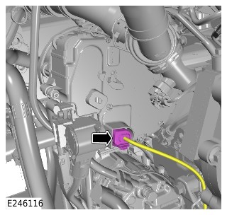
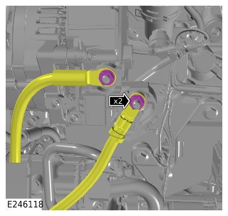
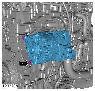
Installation
- Install the BISG.
- Install and tighten the 2 bolts.Torque: 47.5Nm
- Connect the 2 cables to the BISG.
- Install and tighten the 2 nuts.Torque: 12Nm
- Install the BISG connector cover.
- Connect the BISG electrical connector.
- Install the electric cooling fan and shroud.Refer to: Electric Cooling Fan and Shroud - Vehicles With: MHEV (303-03C Engine Cooling - INGENIUM I3 1.5L Petrol, Removal and Installation).
- Install the hood latch panel.Refer to: Hood Latch Panel (501-02 Front End Body Panels, Removal and Installation).
- Install the BISG tensioner.Refer to: Belt Integrated Starter Generator Tensioner (303-05C Accessory Drive - INGENIUM I3 1.5L Petrol, Vehicles With: MHEV, Removal and Installation).
- Power Up the MHEV system.Refer to: MHEV Power Down/Up (414-01 Battery, Mounting and Cables - Vehicles With: MHEV, General Procedures).
- If a new BISG has been installed, use the Jaguar Land Rover (JLR) approved diagnostic equipment to configure the BISG to the BISG inverter. SRO to be claimed separately.General Equipment: LandRover approved diagnostic tool
PHEV Power Down/Up – Complete Vehicle (G3342345)
GENERAL PROCEDURES
- 01.01.61
- PHEV - Power Down/Up - Complete Vehicle
- 1500 cc, Ingenium PHEV
- 1.50
- USED WITHINS
Special Tool(s)

C.A 773
Voltage Indicator
JLR-415-024
Protective Sticker
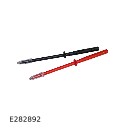
JLR-415-092
Measurement Probes (GS38)
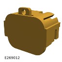
JLR-415-114
Main High Voltage (HV) Connector Lock-off
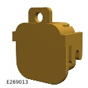
JLR-415-115
Lock Off - High Voltage (HV) Auxiliary Circuit

JLR-415-116
Master Service Disconnect (MSD) Lock-off (CATL Battery)
JLR-415-132
Universal Cable Lock-off
JLR-415-133
12 Volt Battery Lock-off
JLR-415-134
Main High Voltage connector break-out box
JLR-415-135
Main High Voltage connector break-out box safety check connector
JLR-415-136
Break Out Box - High Voltage (HV) Auxiliary Circuit Connector
JLR-415-137
Break Out Box Safety Check Connector – High Voltage (HV) Auxiliary Circuit Connector
PU690
Voltage Tester Proving Unit
General Equipment
| Equipment name |
|---|
| LandRover approved diagnostic tool |
| Insulated padlock |
| Jaguar Land Rover approved diagnostic equipment |
Depower
WARNING:
- This procedure must be completed in the exact sequence shown. Failure to do so could result in serious personal injury.
- It is the responsibility of the Electric Vehicle Senior Authorized Person (EVSAP) or the Electric Vehicle Authorized Person (EVAP) to make sure they comply with any local legislation regarding working with high Voltages, when carrying out this procedure.
- This procedure requires the use Class 0 Personal Protective Equipment (PPE), all persons involved in this procedure must have read and understood the PPE requirements as detailed in section 414-01B Electric Vehicle Safety Rules.
- The approved PPE must be worn where indicated by the orange PPE icons within this procedure, all persons involved in this procedure must have read and understood section 100-00 of this manual before continuing.
- All safety locking device keys must be kept in the designated key lock box at least 5 meters away from the vehicle.
NOTE:
- All Permit To Work Permit To Work (PTW) documents must be kept for a minimum of 5 years.
- This procedure contains illustrations showing certain components removed to provide extra clarity.
- This procedure contains some variation in the illustrations depending on the vehicle specification, but the essential information is always correct.
- This procedure is only required if the Plug-in Hybrid Electric Vehicle (PHEV) battery is being removed from the vehicle. If components within the High Voltage (HV) system require repair, follow the workshop manual procedure for these components and power down the specific HV system circuit associated with that component.
- WARNING:
Jaguar Land Rover (JLR) EVAP trained technicians only.
Position the EV safety barrier around the vehicle at a minimum distance of 1 meter to all points on the vehicle.
- Before handling any HV connectors the EVAP must refer to the HV electrical connector operation and inspection document.Refer to: High Voltage Electrical Connector Operation and Inspection (414-01C Battery, Mounting and Cables - PHEV, General Procedures).
- WARNING:
If any Diagnostic Trouble Codes (DTC)s relating to the HV system are present, the vehicle must be quarantined.
- Check the instrument cluster for warning symbols and messages.
- Use the approved JLR approved diagnostic equipment to complete a diagnostic check on the vehicle for any stored DTCs relating to the HV system.General Equipment: Jaguar Land Rover approved diagnostic equipment
- If any of the following DTCs are stored, do not continue with the PHEV power down/up procedure and follow the approved process for EV quarantine.Refer to: Electric Vehicle Quarantine (414-01 Battery, Mounting and Cables - Vehicles With: PHEV, General Procedures).
- P0AA1-00 Hybrid/Electric Vehicle Battery Positive Contactor Circuit Stuck Closed.
- P0AA4-00 Hybrid/Electric Vehicle Battery Negative Contactor Circuit Stuck Closed.
- P0A7E-00 Hybrid/Electric Vehicle Battery Pack Over Temperature.
- P0A7E-4B Hybrid/Electric Vehicle Battery Pack Over Temperature.
- If any other HV system related DTCs are stored, these must be investigated using the JLR approved diagnostic equipment.
- Complete the application to release the Electric Park Brake (EPB).General Equipment: LandRover approved diagnostic tool
- If required, you can perform the manual EPB release procedure.Refer to: Electric Park Brake Service Mode Activation and Deactivation (206-05 Parking Brake and Actuation, General Procedures).
- Make sure that the vehicle is in PARK, the EPB is released, the ignition is switched off and the doors are unlocked.
- Open the hood.
Remove all smart keys from the vehicle and store at least 5 meters away from the vehicle, locked in the designated key box. Press the ignition switch to verify that there is no communication with the smart key.
- Make sure that the appropriate sign is displayed on the vehicle windshield. The sign should state that:
- The vehicle HV electrical system is operational.
- The vehicle HV electrical system is active.
- WARNING:
All external 12 volt sources must be disconnected from the vehicle before proceeding.
Make sure that all external 12 volt sources are disconnected from the vehicle. For example; towbar sockets, 12 volt accessory sockets and charging points. - WARNING:
Work must not be completed on the EV while connected to an external HV power source, failure to follow this instruction may result in serious personal injury.
Disconnect the vehicle from any external HV power source. Apply the protective sticker to the charge flap on the vehicle as shown in the illustration, make sure the charge flap can not be opened when applied.Special Tool(s): JLR-415-024
- Remove the engine compartment cross brace.Refer to: Engine Compartment Cross Brace (501-02 Front End Body Panels, Removal and Installation).
- Remove the nut.
- Release the battery negative cable from the Battery Monitoring Sensor (BMS).
Disconnect the electrical connector from the BMS.
- Loosen the nut.
- Reposition the battery negative terminal and BMS away from the battery.
- WARNING:
The key must be placed in the designated key box by the responsible EVAP.
- Remove the lock-off tool lid.Special Tool(s): JLR-415-132
- Install the battery negative cable in the lock-off tool.
- Install the lock-off tool lid.
- Install the insulated padlock.General Equipment: Insulated padlock
- Release the 2 clips.
- Remove the Battery Junction Box (BJB) lid.
- Remove the nut.
- Release the Direct Current to Direct Current (DC/DC) cable from the BJB.
- WARNING:
The key must be placed in the designated key box by the responsible EVAP.
- Remove the lock-off tool lid.Special Tool(s): JLR-415-133
- Install the DC/DC cable in the lock-off tool.
- Install the lock-off tool lid.
- Install the insulated padlock.General Equipment: Insulated padlock
- Raise and support the vehicle on a suitable 2 post lift.Refer to: Jacking and Lifting (100-02 Jacking and Lifting, Description and Operation).
Remove the 9 clips.
Remove the nut.
Remove the 7 bolts.
- CAUTION:
This step requires the aid of another technician.
- Remove the 6 bolts.
- Remove the undershield.
- CAUTION:
This step requires the aid of another technician.
- Remove the 6 bolts.
- Release the wiring harness.
- Remove the undershield.
Disconnect the electrical connector.
 All steps showing the Safety Accompanying Person icon require an Electric Vehicle Informed Person (EVIP) JLR certified person who has also completed EDA102940 EV Roles and Responsibilities training, within the vicinity of the power down procedure. This person must have access to the safety hook at all times.
-


- Remove the 4 bolts.
- Remove the Master Service Disconnect (MSD) access panel.
-
Follow the disconnect stages shown in the illustration and remove the MSD from the vehicle.
-
WARNING:
The key must be placed in the designated key box by the responsible EVAP.
- Install the lock-off tool base plate.Special Tool(s): JLR-415-116
- Install and tighten the 4 bolts.Torque: 6Nm
- Install the lock-off tool.
- Install the insulated padlock.General Equipment: Insulated padlock
- WARNING:
If this step is not followed there could potentially be residual voltage in the HV system.
Allow a minimum of 10 minutes for the HV system to completely discharge.
-
Disconnect the auxiliary circuit HV electrical connector.
-
WARNING:
The key must be placed in the designated key box by the responsible EVAP.
- Remove the cover.
- Install the lock-off tool.Special Tool(s): JLR-415-115
- Install the insulated padlock.General Equipment: Insulated padlock
- WARNING:
- Make sure that the voltage indicator is checked to be working before testing the HV system.
- If the equipment test fails, it should not be used in this procedure.
Complete a self test on the voltage indicator before and after each voltage check. For further instructions on the self test procedure, refer to the manufacturers instructions before continuing with this procedure.Special Tool(s): C.A 773
- WARNING:
If the equipment test fails, it should not be used in this procedure.
- The voltage testing equipment must be tested using the voltage proving unit.Special Tool(s): PU690
- Install the voltage tester into the voltage proving unit as illustrated.
- The displayed LEDs should match the illustration.
Install the safety check connector to the breakout box as illustrated.Special Tool(s): JLR-415-136, JLR-415-137
- WARNING:
If the equipment test fails, it should not be used in this procedure.
Use a suitable calibrated digital multimeter to test the continuity of the breakout box. Test the breakout box at the HV+ and HV- terminals. The result should be 440kΩ ± 5kΩ.
-
Install the breakout box to the HV electrical connector.
-
- Use the voltage indicator to test for voltage at the HV+ and HV- terminals.
- If the voltage indicator records below 10V, the result is a pass, continue to the next step.
- WARNING:
If the Electric Vehicle Power Down application resulted in a failed voltage test, DO NOT disconnect the breakout box.
If the voltage indicator records above 10V, repeat steps 38-39 and repeat this step. If this results in a second failure, contact JLR Technical Assistance (TA). Do not continue with this procedure.
-
- Install probe tip JLR-415-092 to the negative side of the voltage indicator, as shown in the illustration and complete the test from steps 48-49.Special Tool(s): JLR-415-092
- Use the voltage indicator to test for voltage between HV+ terminal and the ground point illustrated.
- If the voltage indicator records below 10V, the result is a pass, continue to the next step.
- WARNING:
If the Electric Vehicle Power Down application resulted in a failed voltage test, DO NOT disconnect the breakout box.
If the voltage indicator records above 10V, repeat steps 48-49 and repeat this step. If this results in a second failure, contact JLR TA. Do not continue with this procedure.
-
- Install probe tip JLR-415-092 to the negative side of the voltage indicator, as shown in the illustration and complete the test from steps 48-49.Special Tool(s): JLR-415-092
- Use the voltage indicator to test for voltage between HV- terminal and the ground point illustrated.
- If the voltage indicator records below 10V, the result is a pass, continue to the next step.
- WARNING:
If the Electric Vehicle Power Down application resulted in a failed voltage test, DO NOT disconnect the breakout box.
If the voltage indicator records above 10V, repeat steps 38-39 and repeat this step. If this results in a second failure, contact JLR TA. Do not continue with this procedure.
- WARNING:
The voltage indicator must be tested for correct operation after each voltage test on the HV system.
Repeat the voltage indicator self test process as detailed in steps 38-39 before continuing. -
- WARNING:
The HV breakout box must be tested for correct operation after each voltage test on the HV system.
Repeat a continuity test on the HV breakout box as detailed in steps 40-42 before continuing. -
Disconnect the Belt Integrated Starter Generator (BISG) circuit HV electrical connector.
-
WARNING:
The key must be placed in the designated key box by the responsible EVAP.
- Remove the cover.
- Install the lock-off tool.Special Tool(s): JLR-415-114
- Install the cover.
- Install the insulated padlock.General Equipment: Insulated padlock
- WARNING:
The voltage indicator must be tested for correct operation after each voltage test on the HV system.
Repeat the voltage indicator self test process as detailed in steps 38-39 before continuing. Install the safety check connector to the breakout box as illustrated.Special Tool(s): JLR-415-134, JLR-415-135
- WARNING:
If the equipment test fails, it should not be used in this procedure.
Use a suitable calibrated digital multimeter to test the continuity of the breakout box. Test the breakout box at the HV+ and HV- terminals. The result should be 440kΩ ± 5kΩ.
-
Install the breakout box to the HV electrical connector.
-
- Use the voltage indicator to test for voltage at the HV+ and HV- terminals.
- If the voltage indicator records below 10V, the result is a pass, continue to the next step.
- WARNING:
If the Electric Vehicle Power Down application resulted in a failed voltage test, DO NOT disconnect the breakout box.
If the voltage indicator records above 10V, repeat steps 38-39 and repeat this step. If this results in a second failure, contact JLR TA. Do not continue with this procedure.
-
- Install probe tip JLR-415-092 to the negative side of the voltage indicator, as shown in the illustration and complete the test from steps 48-49.Special Tool(s): JLR-415-092
- Use the voltage indicator to test for voltage between HV+ terminal and the ground point illustrated.
- If the voltage indicator records below 10V, the result is a pass, continue to the next step.
- WARNING:
If the Electric Vehicle Power Down application resulted in a failed voltage test, DO NOT disconnect the breakout box.
If the voltage indicator records above 10V, repeat steps 38-39 and repeat this step. If this results in a second failure, contact JLR TA. Do not continue with this procedure.
-
- Install probe tip JLR-415-092 to the negative side of the voltage indicator, as shown in the illustration and complete the test from steps 48-49.Special Tool(s): JLR-415-092
- Use the voltage indicator to test for voltage between HV- terminal and the ground point illustrated.
- If the voltage indicator records below 10V, the result is a pass, continue to the next step.
- WARNING:
If the Electric Vehicle Power Down application resulted in a failed voltage test, DO NOT disconnect the breakout box.
If the voltage indicator records above 10V, repeat steps 38-39 and repeat this step. If this results in a second failure, contact JLR TA. Do not continue with this procedure.
- WARNING:
The voltage indicator must be tested for correct operation after each voltage test on the HV system.
Repeat the voltage indicator self test process as detailed in steps 38-39 before continuing. -
- WARNING:
The HV breakout box must be tested for correct operation after each voltage test on the HV system.
Repeat a continuity test on the HV breakout box as detailed in steps 63-65 before continuing. -
Disconnect the Electric Rear Axle Drive (eRAD) circuit HV electrical connector.
-
WARNING:
The key must be placed in the designated key box by the responsible EVAP.
- Remove the cover.
- Install the lock-off tool.Special Tool(s): JLR-415-114
- Install the cover.
- Install the insulated padlock.General Equipment: Insulated padlock
- WARNING:
The voltage indicator must be tested for correct operation after each voltage test on the HV system.
Repeat the voltage indicator self test process as detailed in steps 38-39 before continuing. - WARNING:
The HV breakout box must be tested for correct operation after each voltage test on the HV system.
Repeat a continuity test on the HV breakout box as detailed in steps 53-55 before continuing. -
-
- Use the voltage indicator to test for voltage at the HV+ and HV- terminals.
- If the voltage indicator records below 10V, the result is a pass, continue to the next step.
- WARNING:
If the Electric Vehicle Power Down application resulted in a failed voltage test, DO NOT disconnect the breakout box.
If the voltage indicator records above 10V, repeat steps 38-39 and repeat this step. If this results in a second failure, contact JLR TA. Do not continue with this procedure.
-
- Install probe tip JLR-415-092 to the negative side of the voltage indicator, as shown in the illustration and complete the test from steps 48-49.Special Tool(s): JLR-415-092
- Use the voltage indicator to test for voltage between HV+ terminal and the ground point illustrated.
- If the voltage indicator records below 10V, the result is a pass, continue to the next step.
- WARNING:
If the Electric Vehicle Power Down application resulted in a failed voltage test, DO NOT disconnect the breakout box.
If the voltage indicator records above 10V, repeat steps 38-39 and repeat this step. If this results in a second failure, contact JLR TA. Do not continue with this procedure.
-
- Install probe tip JLR-415-092 to the negative side of the voltage indicator, as shown in the illustration and complete the test from steps 48-49.Special Tool(s): JLR-415-092
- Use the voltage indicator to test for voltage between HV- terminal and the ground point illustrated.
- If the voltage indicator records below 10V, the result is a pass, continue to the next step.
- WARNING:
If the Electric Vehicle Power Down application resulted in a failed voltage test, DO NOT disconnect the breakout box.
If the voltage indicator records above 10V, repeat steps 38-39 and repeat this step. If this results in a second failure, contact JLR TA. Do not continue with this procedure.
- WARNING:
The voltage indicator must be tested for correct operation after each voltage test on the HV system.
Repeat the voltage indicator self test process as detailed in steps 38-39 before continuing. -
- WARNING:
The HV breakout box must be tested for correct operation after each voltage test on the HV system.
Repeat a continuity test on the HV breakout box as detailed in steps 53-55 before continuing. - If the EV power down has been successful in recording no results from the voltage tests, proceed to step 75.
- If the EV power down has been unsuccessful, meaning a voltage has been detected during the tests, proceed to step 74.
- Quarantine the vehicle and contact JLR TA.
- Make sure that the appropriate sign is displayed on the vehicle, where it is clearly visible. The sign should state that:
- Danger electrical system live.
- Vehicle electrical system live.
- Make sure that the appropriate sign is displayed on the vehicle, where it is clearly visible. The sign should state that:
- Re-work is in progress.
- The vehicle high voltage electrical system is disabled and safe to work on.
- The vehicle high voltage electrical system is isolated.
- NOTE:
Only an EVAP trained technician can issue a PTW.
A PTW can now be issued by the EVAP using the instruction detailed in the EV safety rules.

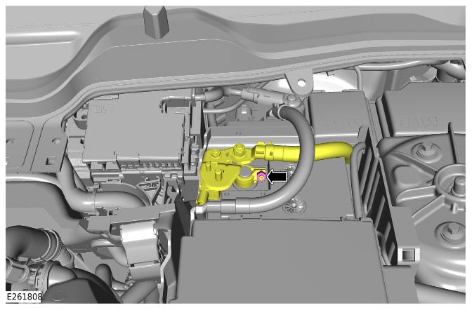
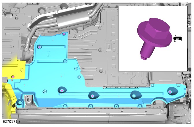
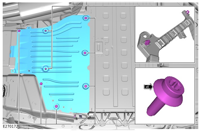
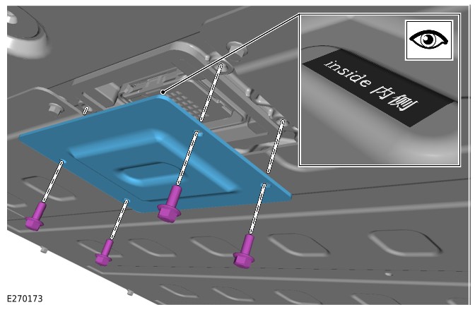
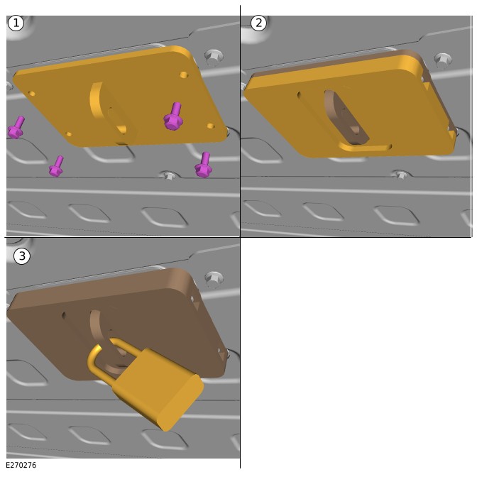
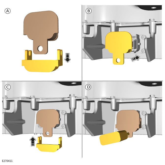
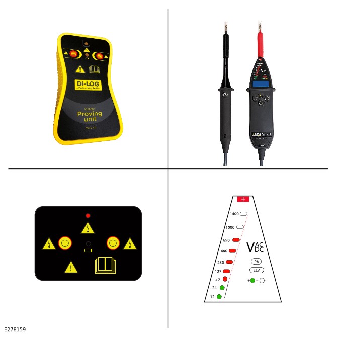
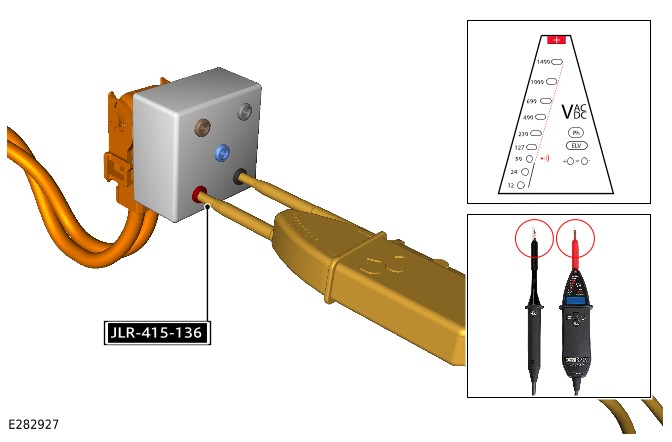
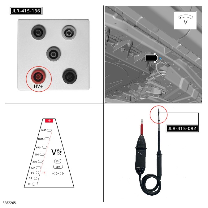
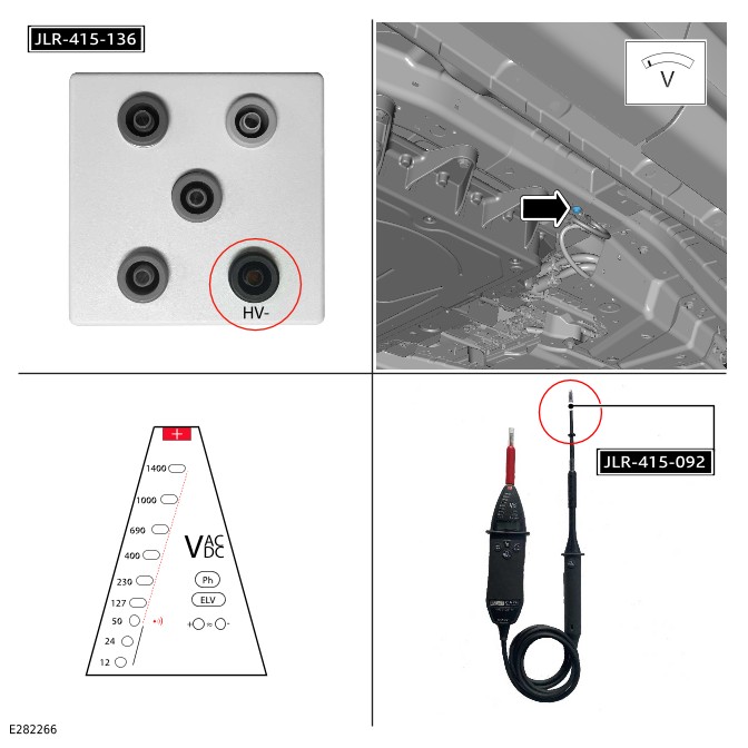
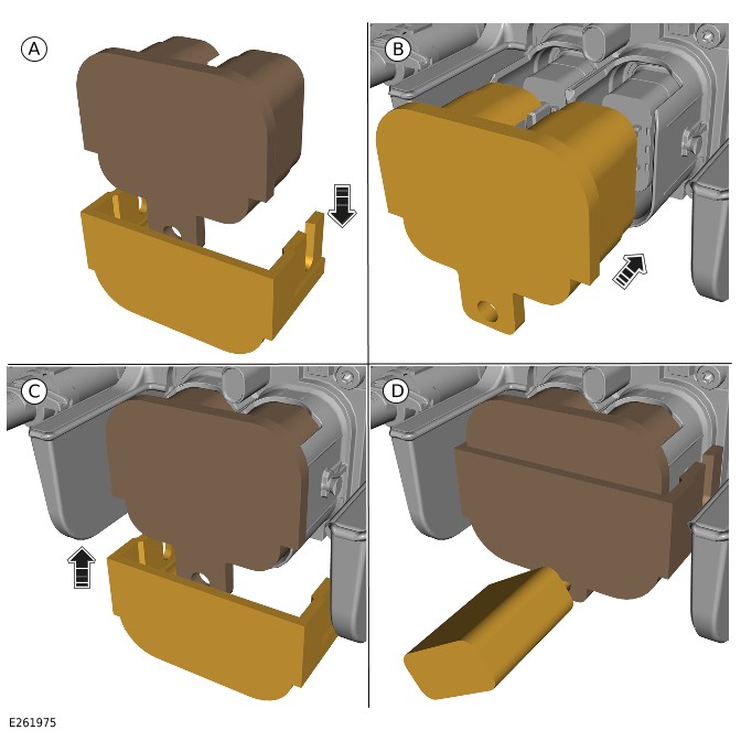
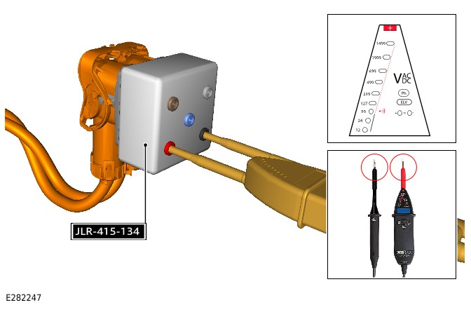
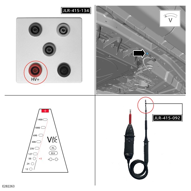
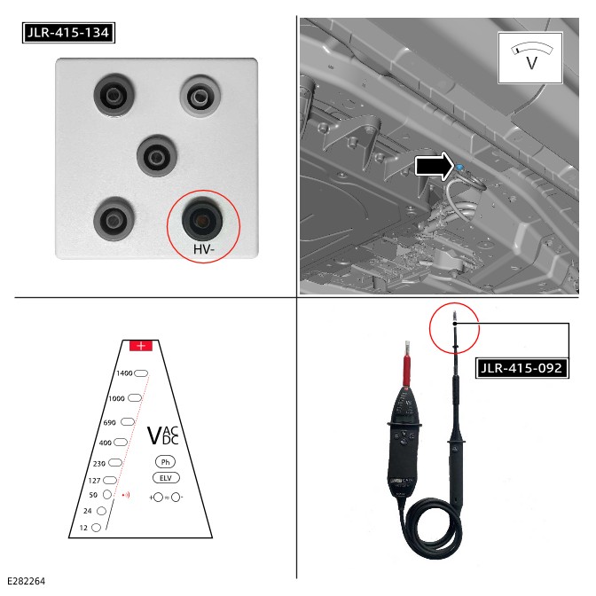


Repower
- The EVAP must make sure any Electric Vehicle Competent Person (EVCP) and members of the working party have been informed that no further work can be performed on the vehicle, the EVCP must sign the clearance section of the PTW before handing the vehicle responsibility to the EVAP.
- Remove the safe status sign and display the active sign where it is clearly visible. The sign should state that:
- The vehicle HV electrical system is operational.
- The vehicle HV electrical system is active.
-
The following steps require the Safety Accompanying Person (EVIP JLR certified person who has also completed EDA102940 EV Roles and Responsibilities training.) within the vicinity of the power down procedure. This person must have access to the safety hook at all times.
-
- Remove the insulated padlock.
- Remove the cover.
- Remove the lock-off tool.
-
-
- Remove the insulated padlock.
- Remove the cover.
- Remove the lock-off tool.
-
eRADHV
-
- Remove the insulated padlock.
- Remove the cover.
- Remove the lock-off tool.
-
BISGHV
-
- Remove the insulated padlock.
- Remove the lock-off tool.
- Remove the 4 bolts.
- Remove the lock-off tool base.
-
Install the in the sequence shown in the illustration.
MSD
-
- Install the access panel.
- Install and tighten the 4 bolts.MSDTorque: 6Nm
- CAUTION:
This step requires the aid of another technician.
- Install the undershield.
- Install the wiring harness.
- Install and tighten the 6 bolts.Torque: 24Nm
- CAUTION:
This step requires the aid of another technician.
- Install the undershield.
- Install and tighten the 6 bolts.Torque: 24Nm
- Remove the insulated padlock.
- Remove the lock-off tool lid.
- Remove the cable from the lock-off tool.
DC/DC
- Install the cable to the .
- Install and tighten the nut.DC/DCBJBTorque: 18Nm
- Install the lid.
BJB
- Install the battery negative terminal and .
- Install and tighten the nut.BMSTorque: 6Nm
- BMS
- Remove the insulated padlock.
- Remove the lock-off tool lid.
- Release the battery negative cable from the lock-off tool.
- Install the battery negative cable to the .
- Install and tighten the nut.BMSTorque: 18Nm
- Install the engine compartment cross brace.Refer to: (501-02 Front End Body Panels, Removal and Installation). Engine Compartment Cross Brace
- Collect the vehicle key and turn on the ignition with brake pedal pressed. The vehicle should now start and display 'ready' on the instrument cluster.
- If the vehicle fails to start, contact .
JLRTA
- Use the approved diagnostic equipment to read and clear the s. JLRDTC
- The must now sign the cancellation and power up sections of the .
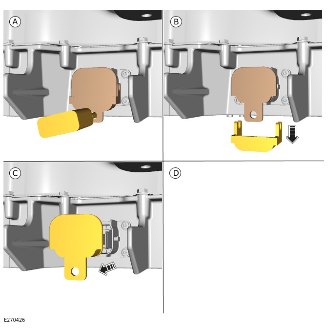
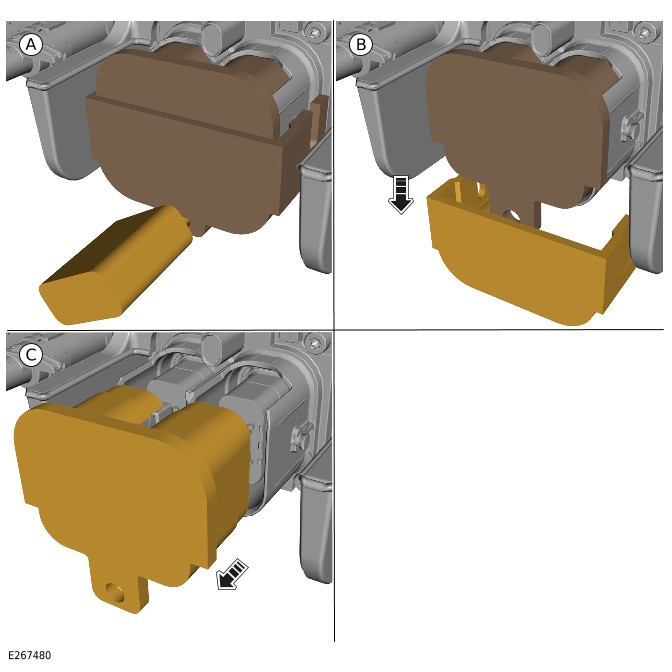
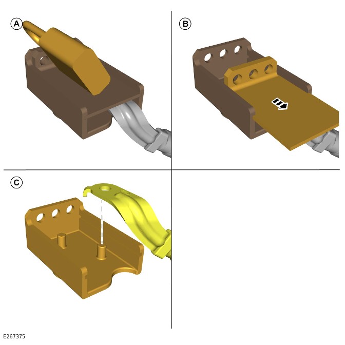
EVAPPTW
PHEV Power Down/Up – Complete Vehicle (G2770160)
GENERAL PROCEDURES
- 01.01.61
- PHEV - Power Down/Up - Complete Vehicle
- 1500 cc, Ingenium PHEV
- 1.50
- USED WITHINS
Special Tool(s)
C.A 773
Voltage Indicator
JLR-415-024
Protective Sticker
JLR-415-092
Measurement Probes (GS38)
JLR-415-114
Main High Voltage (HV) Connector Lock-off
JLR-415-115
Lock Off - High Voltage (HV) Auxiliary Circuit

JLR-415-117
Master Service Disconnect (MSD) Lock-off (SDI Battery)
JLR-415-132
Universal Cable Lock-off
JLR-415-133
12 Volt Battery Lock-off
JLR-415-134
Main High Voltage connector break-out box
JLR-415-135
Main High Voltage connector break-out box safety check connector
JLR-415-136
Break Out Box - High Voltage (HV) Auxiliary Circuit Connector
JLR-415-137
Break Out Box Safety Check Connector – High Voltage (HV) Auxiliary Circuit Connector
PU690
Voltage Tester Proving Unit
General Equipment
| Equipment name |
|---|
| LandRover approved diagnostic tool |
| Insulated padlock |
| Jaguar Land Rover approved diagnostic equipment |
| Padlock |
Depower
WARNING:
- This procedure must be completed in the exact sequence shown. Failure to do so could result in serious personal injury.
- It is the responsibility of the Electric Vehicle Senior Authorized Person (EVSAP) or the Electric Vehicle Authorized Person (EVAP) to make sure they comply with any local legislation regarding working with high Voltages, when carrying out this procedure.
- This procedure requires the use Class 0 Personal Protective Equipment (PPE), all persons involved in this procedure must have read and understood the PPE requirements as detailed in section 414-01B Electric Vehicle Safety Rules.
- The approved PPE must be worn where indicated by the orange PPE icons within this procedure, all persons involved in this procedure must have read and understood section 100-00 of this manual before continuing.
- All safety locking device keys must be kept in the designated key lock box at least 5 meters away from the vehicle.
NOTE:
- All Permit To Work Permit To Work (PTW) documents must be kept for a minimum of 5 years.
- This procedure contains illustrations showing certain components removed to provide extra clarity.
- This procedure contains some variation in the illustrations depending on the vehicle specification, but the essential information is always correct.
- WARNING:
Jaguar Land Rover (JLR) EVAP trained technicians only.
- Before handling any HV connectors the EVAP must refer to the HV electrical connector operation and inspection document.Refer to: High Voltage Electrical Connector Operation and Inspection (414-01C Battery, Mounting and Cables - PHEV, General Procedures).
- Check the Instrument Cluster for Warning symbols and messages.
- WARNING:
If any of the Diagnostic Trouble Codes (DTC) below are present, the vehicle must be quarantined.
If any of the following DTC are stored, do not continue with the Plug-in Hybrid Electric Vehicle (PHEV) power down/up procedure and follow the approved process for EV Quarantine.Refer to: Electric Vehicle Quarantine (414-01C Battery, Mounting and Cables - PHEV, General Procedures).
- Using the JLR approved diagnostic equipment complete a diagnostic check on the vehicle for any stored DTC relating to the HV system.General Equipment: Jaguar Land Rover approved diagnostic equipment
- SDI / CATL / EBC21 P0AA1-00 Hybrid/ EV Battery Positive Contactor Circuit Stuck Closed.
- SDI / CATL / EBC21 P0AA4-00 Hybrid/ EV Battery Negative Contactor Circuit Stuck Closed.
- SDI / CATL / EBC21 P0E74-1A Hybrid/ EV Battery Voltage System Isolation Fault.
- I-pace (X590) P0AA6-00 Hybrid/ EV Battery Voltage System Isolation Fault.
- I-pace (X590) P304F-73 Hybrid/ EV Battery Contactor (A) - Actuator Stuck Closed.
- I-pace (X590) P3050-73 Hybrid/ EV Battery Auxiliary Contactor (B) Fault - Actuator Stuck Closed.
- I-pace (X590) P3051-73 Hybrid/ EV Battery Negative Contactor (C) Fault - Actuator Stuck Closed.
- I-pace (X590) / EBC21 P0A7E-00 Hybrid/ EV Battery Pack Over Temperature.
- PHEV / CATL P0A7E-4B Hybrid/ EV Battery Pack Over Temperature.
- EBC21 P0AA6-1A Hybrid/ EV Battery Voltage System Isolation Fault.
- If any other HV system related DTC are stored, these must be investigated using the JLR approved diagnostic equipment.
- Complete the application to release the Electric Park Brake (EPB).General Equipment: LandRover approved diagnostic tool
- If required, you can perform the manual EPB release procedure.Refer to: Electric Park Brake Service Mode Activation and Deactivation (206-05 Parking Brake and Actuation, General Procedures).
- Make sure that the vehicle is in PARK, the EPB is released, the ignition is switched off and the doors are unlocked.
- Open the hood.
- Make sure that the appropriate sign is displayed on the vehicle windshield. The sign should state that:
- The vehicle HV electrical system is operational.
- The vehicle HV electrical system is active.
- WARNING:
All external 12 volt sources must be disconnected from the vehicle before proceeding.
Make sure that all external 12 volt sources are disconnected from the vehicle. For example; towbar sockets, 12 volt accessory sockets and charging points. - WARNING:
Work must not be completed on the EV while connected to an external HV power source, failure to follow this instruction may result in serious personal injury.
Disconnect the vehicle from any external HV power source. - Remove the engine compartment cross brace.Refer to: Engine Compartment Cross Brace (501-02 Front End Body Panels, Removal and Installation).
- Remove the nut.
- Release the battery negative cable from the Battery Monitoring Sensor (BMS).
- Loosen the nut.
- Reposition the battery negative terminal and BMS.
- WARNING:
The key must be placed in the designated key box by the responsible EVAP.
- Remove the lock-off tool lid.Special Tool(s): JLR-415-132
- Install the battery negative cable in the lock-off tool.
- Install the lock-off tool lid.
- Install the insulated padlock.General Equipment: Insulated padlock
- Release the 2 clips.
- Remove the Battery Junction Box (BJB) lid.
- Remove the nut.
- Release the Direct Current to Direct Current (DC/DC) cable from the BJB.
- WARNING:
The key must be placed in the designated key box by the responsible EVAP.
- Remove the lock-off tool lid.Special Tool(s): JLR-415-133
- Install the DC/DC cable in the lock-off tool.
- Install the lock-off tool lid.
- Install the insulated padlock.General Equipment: Insulated padlock
- NOTE:
This step is applicable to Left Hand Drive vehicles only.
Remove the 2 clips.
- NOTE:
This step is applicable to Left Hand Drive vehicles only.
Carefully reposition the cowl panel to access the connector on the auxiliary battery.
- NOTES:
- This step is applicable to Left Hand Drive vehicles only.
- If equipped.
Disconnect the electrical connector from the auxiliary battery.
- NOTES:
- This step is applicable to Left Hand Drive vehicles only.
- If equipped.
- Remove the nut.
- Release the cable from the Power Supply Distribution Box (PSDB).
- NOTES:
- This step is applicable to Left Hand Drive vehicles only.
- If equipped.
- Remove the bolt.
- Reposition the auxiliary battery negative cable.
- WARNING:
The key must be placed in the designated key box by the responsible EVAP.
NOTE:This step is applicable to Left Hand Drive vehicles only.
- Remove the lock-off tool lid.Special Tool(s): JLR-415-132
- Install the auxiliary battery negative cable in the lock-off tool.
- Install the lock-off tool lid.
- Install the insulated padlock.General Equipment: Insulated padlock
- NOTES:
- This step is applicable to Right Hand Drive vehicles only.
- If equipped.
- NOTES:
- This step is applicable to Right Hand Drive vehicles only.
- If equipped.
- Remove the nut.
- Release the cable from the PSDB.
- WARNING:
The cable must be placed in the designated key box by the responsible EVAP.
NOTES:- If equipped.
- This step is applicable to Right Hand Drive vehicles only.
- Remove the auxiliary battery cable.
- Install the auxiliary battery cable in the designated key box.
- NOTES:
- This step is applicable to Right Hand Drive vehicles only.
- If equipped.
- Remove the nut.
- Reposition the auxiliary battery negative cable.
- NOTES:
- This step is applicable to Right Hand Drive vehicles only.
- If equipped.
- Remove the lock-off tool lid.Special Tool(s): JLR-415-132
- Install the auxiliary battery negative cable in the lock-off tool.
- Install the lock-off tool lid.
- Install the insulated padlock.General Equipment: Insulated padlock
- Raise and support the vehicle on a suitable 2 post lift.Refer to: Jacking and Lifting (100-02 Jacking and Lifting, Description and Operation).
- CAUTION:
This step requires the aid of another technician.
- Remove the 6 bolts.
- Remove the undershield.
- CAUTION:
This step requires the aid of another technician.
- Remove the 6 bolts.
- Release the wiring harness.
- Remove the undershield.
-
All steps showing the Safety Accompanying Person icon require an Electric Vehicle Informed Person (EVIP) JLR certified person who has also completed EDA102940 EV Roles and Responsibilities training, within the vicinity of the power down procedure. This person must have access to the safety hook at all times.
- HV battery without Master Service Disconnect (MSD).
- If the HV battery does not have a MSD, do not complete steps 41 to 45.
-
NOTE:
This step only applies to vehicles equipped with a MSD.
- Remove the 3 bolts.
- Remove the MSD access panel.
-
NOTE:
This step only applies to vehicles equipped with a MSD.
Follow the disconnect stages shown in the illustration.
-
NOTE:
This step only applies to vehicles equipped with a MSD.
Remove the MSD from the vehicle.
-
WARNING:
The key must be placed in the designated key box by the responsible EVAP.
NOTE:This step only applies to vehicles equipped with a MSD.
- Rotate the locking tabs.
- Install the lock-off tool.Special Tool(s): JLR-415-117
- Engage the locking tabs.
- Install the padlock.General Equipment: Padlock
- NOTE:
This step only applies to vehicles equipped with a MSD.
- WARNING:
If this step is not followed there could potentially be residual voltage in the HV system.
-
-
WARNING:
The key must be placed in the designated key box by the responsible EVAP.
- Remove the cover.
- Install the lock-off tool.Special Tool(s): JLR-415-115
- Install the insulated padlock.General Equipment: Insulated padlock
- WARNING:
- Make sure that the voltage indicator is checked to be working before testing the HV system.
- If the equipment test fails, it should not be used in this procedure.
- WARNING:
If the equipment test fails, it should not be used in this procedure.
- The voltage testing equipment must be tested using the voltage proving unit.Special Tool(s): PU690
- Install the voltage tester into the voltage proving unit as illustrated.
- The displayed LEDs should match the illustration.
- WARNING:
If the equipment test fails, it should not be used in this procedure.
-
-
- Use the voltage indicator to test for voltage at the HV+ and HV- terminals.
- If the voltage indicator records below 10V, the result is a pass, continue to the next step.
- WARNING:
If the Electric Vehicle Power Down application resulted in a failed voltage test, DO NOT disconnect the breakout box.
If the voltage indicator records above 10V, repeat steps 50-51 and repeat this step. If this results in a second failure, contact JLR Technical Assistance (TA). Do not continue with this procedure.
-
- Install probe tip JLR-415-092 to the negative side of the voltage indicator, as shown in the illustration and complete the test steps 50-51.Special Tool(s): JLR-415-092
- Use the voltage indicator to test for voltage between HV+ terminal and the ground point illustrated.
- If the voltage indicator records below 10V, the result is a pass, continue to the next step.
- WARNING:
If the Electric Vehicle Power Down application resulted in a failed voltage test, DO NOT disconnect the breakout box.
If the voltage indicator records above 10V, repeat steps 50-51 and repeat this step. If this results in a second failure, contact JLR TA. Do not continue with this procedure.
-
- Use the voltage indicator to test for voltage between HV- terminal and the ground point illustrated.
- If the voltage indicator records below 10V, the result is a pass, continue to the next step.
- WARNING:
If the Electric Vehicle Power Down application resulted in a failed voltage test, DO NOT disconnect the breakout box.
If the voltage indicator records above 10V, repeat steps 50-51 and repeat this step. If this results in a second failure, contact JLR TA. Do not continue with this procedure.
- WARNING:
The voltage indicator must be tested for correct operation after each voltage test on the HV system.
Repeat the voltage indicator self test process as detailed in steps 50-51 before continuing. -
- WARNING:
The HV breakout box must be tested for correct operation after each voltage test on the HV system.
Repeat a continuity test on the HV breakout box as detailed in steps 50-52 before continuing. -
-
WARNING:
The key must be placed in the designated key box by the responsible EVAP.
- Remove the cover.
- Install the lock-off tool.Special Tool(s): JLR-415-114
- Install the cover.
- Install the insulated padlock.General Equipment: Insulated padlock
-
-
WARNING:
The key must be placed in the designated key box by the responsible EVAP.
- Remove the cover.
- Install the lock-off tool.Special Tool(s): JLR-415-114
- Install the cover.
- Install the insulated padlock.General Equipment: Insulated padlock
- WARNING:
If the equipment test fails, it should not be used in this procedure.
-
-
- Use the voltage indicator to test for voltage at the HV+ and HV- terminals.
- If the voltage indicator records below 10V, the result is a pass, continue to the next step.
- WARNING:
If the Electric Vehicle Power Down application resulted in a failed voltage test, DO NOT disconnect the breakout box.
If the voltage indicator records above 10V, repeat steps 50-51 and repeat this step. If this results in a second failure, contact JLR TA. Do not continue with this procedure.
-
- Install probe tip JLR-415-092 to the negative side of the voltage indicator, as shown in the illustration and complete the test steps 50-51.Special Tool(s): JLR-415-092
- Use the voltage indicator to test for voltage between HV+ terminal and the ground point illustrated.
- If the voltage indicator records below 10V, the result is a pass, continue to the next step.
- WARNING:
If the Electric Vehicle Power Down application resulted in a failed voltage test, DO NOT disconnect the breakout box.
If the voltage indicator records above 10V, repeat steps 50-51 and repeat this step. If this results in a second failure, contact JLR TA. Do not continue with this procedure.
-
- Use the voltage indicator to test for voltage between HV- terminal and the ground point illustrated.
- If the voltage indicator records below 10V, the result is a pass, continue to the next step.
- WARNING:
If the Electric Vehicle Power Down application resulted in a failed voltage test, DO NOT disconnect the breakout box.
If the voltage indicator records above 10V, repeat steps 50-51 and repeat this step. If this results in a second failure, contact . Do not continue with this procedure.
JLRTA
- WARNING:
The voltage indicator must be tested for correct operation after each voltage test on the system.
Repeat the voltage indicator self test process as detailed in steps 50-51 before continuing. HV
-
HV
- WARNING:
The breakout box must be tested for correct operation after each voltage test on the system.
Repeat a continuity test on the breakout box as detailed in steps 64-66 before continuing. HVHVHV
- NOTE:
If both electrical connectors have been disconnected the test must be repeated and the absence of voltage confirmed for each of the electrical connectors before continuing.
Repeat steps 64-73 for the other electrical connector . HVHVHV
- If the power down has been successful in recording no results from the voltage tests, proceed to step 79.
- If the power down has been unsuccessful, meaning a voltage has been detected during the tests, proceed to step 78.
EVEV
-
- Quarantine the vehicle and contact .JLRTARefer to: (414-01C Battery, Mounting and Cables - PHEV, General Procedures).
- Make sure that the appropriate sign is displayed on the vehicle, where it is clearly visible. The sign should state that:
- Danger electrical system live.
- Vehicle electrical system live.
Electric Vehicle Quarantine
- Make sure that the appropriate sign is displayed on the vehicle, where it is clearly visible. The sign should state that:
- Re-work is in progress.
- The vehicle electrical system is disabled and safe to work on.
- The vehicle electrical system is isolated.
HVHV
- NOTE:
Only a trained technician can issue a .
A can now be issued by the using the instruction detailed in the safety rules.
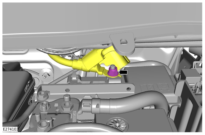
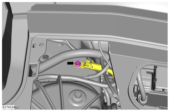
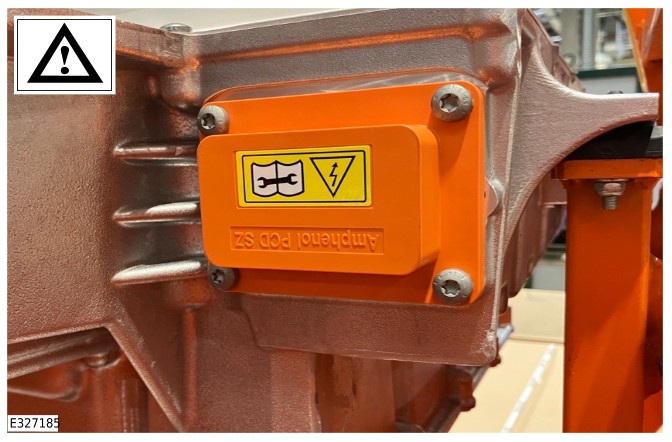
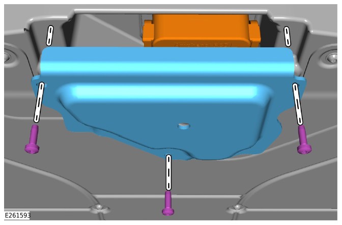
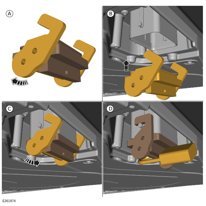
EVAPPTWPTWEVAPEV
Repower
- The must make sure any Electric Vehicle Competent Person (EVCP) and members of the working party have been informed that no further work can be performed on the vehicle, the must sign the clearance section of the before handing the vehicle responsibility to the . EVAPEVCPPTWEVAP
- Remove the safe status sign and display the active sign where it is clearly visible. The sign should state that:
- The vehicle electrical system is operational.
- The vehicle electrical system is active.
HVHV
-
- Remove the insulated padlock.
- Remove the cover.
- Remove the lock-off tool.
-
HV
-
The following steps require the Safety Accompanying Person ( certified person who has also completed EDA102940 Roles and Responsibilities training.) within the vicinity of the power down procedure. This person must have access to the safety hook at all times. EVIPJLREV
-
- Remove the insulated padlock.
- Remove the cover.
- Remove the lock-off tool.
-
NOTE:
This step is only require if the electrical connector was removed during the power down procedure.
eRADHV
-
NOTE:
This step is only require if the electrical connector was removed during the power down procedure.
BISGHV
-
NOTE:
This step only applies to vehicles equipped with a .
MSD- Remove the insulated padlock.
- Disengage the locking tabs.
- Remove the lock-off tool.
-
NOTE:
This step only applies to vehicles equipped with a .
MSDInstall the in the sequence shown in the illustration.
MSD
-
NOTE:
This step only applies to vehicles equipped with a .
MSD- Install the access panel.
- Install and tighten the 3 bolts.MSDTorque: 6Nm
- NOTE:
With the aid of a second technician.
- Install the undershield.
- Install the wiring harness.
- Install and tighten the 6 bolts.Torque: 24Nm
- NOTE:
With the aid of a second technician.
- Install the undershield.
- Install and tighten the 6 bolts.Torque: 7Nm
- Remove the padlock.
- Remove the lock off tool lid.
- Release the auxiliary battery negative cable from the lock-off tool.
- NOTE:
This step is applicable to Right Hand Drive vehicles only.
- Install the auxiliary battery negative cable.
- Install and tighten the nut.Torque: 18Nm
- NOTE:
This step is applicable to Right Hand Drive vehicles only.
Install the auxiliary battery cable.
- NOTE:
This step is applicable to Right Hand Drive vehicles only.
- Install the cable to the power supply distribution box.
- Install and tighten the nut.Torque: 18Nm
- NOTE:
This step is applicable to Right Hand Drive vehicles only.
Remove the cable from the lock out tool.
DC/DC
- Install the cable.
- Install and tighten the nut.DC/DCTorque: 18Nm
- Remove the padlock.
- Remove the lock off tool lid.
- Release the auxiliary battery negative cable from the lock-off tool.
- NOTE:
This step is applicable to Left Hand Drive vehicles only.
- Install the auxiliary battery negative cable.
- Install and tighten the nut.Torque: 18Nm
- NOTE:
This step is applicable to Left Hand Drive vehicles only.
- Install the cable to the power supply distribution box.
- Install and tighten the nut.Torque: 18Nm
- NOTE:
This step is applicable to Left Hand Drive vehicles only.
- NOTE:
This step is applicable to Left Hand Drive vehicles only.
- NOTE:
This step is applicable to Left Hand Drive vehicles only.
- Install the battery negative terminal and .
- Tighten the nut.BMSTorque: 6Nm
- BMS
- WARNING:
The key must be placed in the designated key box by the responsible .
EVAP- Remove the padlock.
- Remove the lock off tool lid.
- Release the battery negative cable from the lock-off tool.
- Install the battery negative cable to the .
- Install and tighten the nut.BMSTorque: 18Nm
- Install the engine compartment cross brace.Refer to: (501-02 Front End Body Panels, Removal and Installation). Engine Compartment Cross Brace
- Collect the vehicle key and turn on the ignition with brake pedal pressed. The vehicle should now start and display 'ready' on the instrument cluster.
- If the vehicle fails to start, contact .
JLRTA
- Use the approved diagnostic equipment to read and clear the s. JLRDTC
- The must now sign the cancellation and power up sections of the .
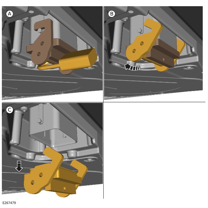
EVAPPTW
PHEV Battery (G2770339)
REMOVAL AND INSTALLATION
- 15.10.13
- High Voltage Battery Pack - Renew
- 1500 cc, Ingenium PHEV
- 3.60
- USED WITHINS
General Equipment
| Equipment name |
|---|
| Fluke 1507 Insulation Tester |
| Jaguar Land Rover approved diagnostic equipment |
| Transmission jack |
Removal
WARNING:
- It is the responsibility of the Electric Vehicle Authorized Person (EVAP) to make sure they comply with any local legislation for work on High Voltage (HV).
- The approved Personal Protective Equipment (PPE) must be worn where indicated within this procedure and not removed unless indicated within a step. All items of PPE must be checked for signs of damage before each use, if damaged, replacement PPE must be obtained before doing this procedure.
- If the vehicle has been powered down, do not power up the vehicle until all the bonding points have been tested.
CAUTION:
- Make sure all the HV connectors, ground points and locating points are clean and free from foreign material before disconnecting and connecting.
- Before disconnecting any components, make sure the area is clean and free from foreign material. When disconnected all openings must be sealed.
NOTE:
- All Permit To Work (PTW) documents must be kept for a minimum of 5 years.
- This procedure contains some variation in the illustrations depending on the vehicle specification, but the essential information is always correct.
- This procedure contains illustrations showing certain components removed to provide extra clarity.
- If the Plug-in Hybrid Electric Vehicle (PHEV) battery pack is being replaced a printed copy of the State Of Charge (SOC) report must be placed in the old PHEV battery pack return packaging.
- It is mandated that all technicians involved with the steps in this procedure have read and understood the Electric Vehicle (EV) Safety Rules.Refer to: Electric Vehicle Safety Rules (414-01C Battery, Mounting and Cables - PHEV, Description and Operation).
- Before handling any HV connectors the person(s) completing this procedure must refer to the 'High Voltage Electrical Connector Operation and Inspection' document.Refer to: High Voltage Electrical Connector Operation and Inspection (414-01C Battery, Mounting and Cables - PHEV, General Procedures).
- Before handling the PHEV battery the person(s) completing this procedure must refer to the 'PHEV Battery Handling and Storage' document.Refer to: PHEV Battery Handling and Storage (414-01C Battery, Mounting and Cables - PHEV, General Procedures).
- NOTE:
If the PHEV battery is to be removed for access do not complete this step.
Complete the Battery Energy Control Module (BECM) - Traction Battery State of Health Overview and attach a copy inside the PHEV battery return packaging. - NOTE:
If the PHEV battery is to be removed for access do not complete this step.
Complete the Hybrid Battery Assessment and attach a copy inside the PHEV battery return packaging.Refer to: Hybrid Battery Assessment (414-01C Battery, Mounting and Cables - PHEV, Description and Operation). - Raise and support the vehicle on a suitable 2 post lift.Refer to: Jacking and Lifting (100-02 Jacking and Lifting, Description and Operation).
- WARNING:
Jaguar Land Rover (JLR) EVAP trained technicians only.
- WARNING:
JLR Electric Vehicle Competent Person (EVCP) trained technicians only.
- Remove the exhaust system.Refer to: Exhaust System (309-00D Exhaust System - INGENIUM I3 1.5L Petrol, PHEV, Removal and Installation).
- Remove the 4 nuts.
- Remove the 3 bolts.
- Remove the heatshield.
- Drain the PHEV battery cooling system.Refer to: PHEV Battery Cooling System Draining and Vacuum Filling (414-01C Battery, Mounting and Cables - PHEV, General Procedures).
- WARNING:
Be prepared to collect escaping coolant.
Disconnect the 2 coolant hoses.
Disconnect the breather pipe.
Remove the nut and reposition the ground cable.
Remove the 2 bolts.
Position a suitable stand as illustrated.General Equipment: Transmission jack
- Use a suitable stand to support the PHEV battery.General Equipment: Transmission jack
- Remove the 6 bolts.
- Remove the PHEV battery from the vehicle.
- Refer to the Electric Vehicle Battery Storage procedure for details on how to handle and store a PHEV battery.Refer to: PHEV Battery Handling and Storage (414-01C Battery, Mounting and Cables - PHEV, General Procedures).
Installation
- Use a suitable stand to install the PHEV battery to the vehicle.General Equipment: Transmission jack
- Make sure the PHEV battery is correctly located on the locating pins on both sides.
- Install and tighten the 8 bolts.Torque: 60Nm
Install and tighten the 6 bolts.Torque: 60Nm
- Remove the suitable stand.General Equipment: Transmission jack
- Reposition the ground cable.
- Install and tighten the nut.Torque: 4.8Nm
- WARNING:
Make sure the bonding test is done before the Power Up HV system procedure.
- Use General Equipment Fluke 1507 Insulation Tester to complete the EV bonding test.General Equipment: Fluke 1507 Insulation Tester
- A) Connect the probe to the casing of PHEV battery.
- B) Connect the probe to the ground point.
- The bonding test can only be passed if a reading of under 50 milliohms is achieved. Any measurement above this must be investigated.
- Connect the breather pipe.
- Connect the 2 cooling hoses.
- Install the exhaust heatshield.
- Install and tighten the 4 nuts.Torque: 5.4Nm
- Install and tighten the 3 bolts.Torque: 10Nm
- Install the exhaust system.Refer to: Exhaust System (309-00D Exhaust System - INGENIUM I3 1.5L Petrol, PHEV, Removal and Installation).
- WARNING:
JLR EVAP trained technicians only.
- Bleed the PHEV battery cooling system.Refer to: PHEV Battery Cooling System Draining and Vacuum Filling (414-01C Battery, Mounting and Cables - PHEV, General Procedures).
- If a new PHEV battery has been installed, use the JLR approved diagnostic equipment to configure the BECM. SRO to be claimed separately.General Equipment: Jaguar Land Rover approved diagnostic equipment