WSM-60255 - Workshop manual - Defender (LE) 2025

Sunday, July 26, 2026
by JLR Dealer Tool Kits Worldwide shipping

Published: 10-Mar-2020

2025.0 Defender (LE), 100-00

General Information

Diagnostic Trouble Code Index: Transmission Control Switch (TCS) (G2400923)

DESCRIPTION AND OPERATION

Gear Shift Module (GSM)

CAUTION:

Diagnosis by substitution from a donor vehicle is NOT acceptable. Substitution of control modules does not guarantee confirmation of a fault, and may also cause additional faults in the vehicle being tested and/or the donor vehicle.

NOTES:

  • If a control module or a component is not to specification and the vehicle remains under manufacturer warranty, refer to the Warranty Policy and Procedures manual, or determine if any prior approval program is in operation, prior to the installation of a new module/component.
  • Generic scan tools may not read the codes listed, or may read only 5-digit codes. Match the 5 digits from the scan tool to the first 5 digits of the 7-digit code listed to identify the fault (the last 2 digits give extra information read by the Jaguar Land Rover approved diagnostic equipment).
  • When performing voltage or resistance tests, always use a digital multimeter that has the resolution ability to view 3 decimal places. For example, on the 2 volts range can measure 1 mV or 2 kΩ range can measure 1 Ω. When testing resistance always take the resistance of the digital multimeter leads into account.
  • Check and rectify basic faults before beginning diagnostic routines involving pinpoint tests.
  • Inspect connectors for signs of water ingress, and pins for damage and/or corrosion.
  • If Diagnostic Trouble Code(s) are recorded and, after performing the pinpoint tests, a fault is not present, an intermittent concern may be the cause. Always check for loose connections and corroded terminals.
  • Check JLR claims submission system for open campaigns. Refer to the corresponding bulletins and SSMs which may be valid for the specific customer complaint and complete the recommendations as required.

The table below lists all the Diagnostic Trouble Code(s) that could be set in the Gear Shift Module (GSM). For additional diagnosis and testing information, refer to the relevant Diagnosis and Testing section in the workshop manual. For additional information, refer to: External Controls (311-02 Automatic Transmission External Controls, Diagnosis and Testing).

Diagnostic Trouble Code Index - INGENIUM I6 3.0L Diesel, MHEV, DTC: Powertrain Control Module (PCM) (G2895551)

DESCRIPTION AND OPERATION

Powertrain Control Module (PCM) - Ingenium I6 3.0L Diesel - Mild Hybrid Electric Vehicle (MHEV)

CAUTION:

Diagnosis by substitution from a donor vehicle is NOT acceptable. Substitution of control modules does not guarantee confirmation of a fault, and may also cause additional faults in the vehicle being tested and/or the donor vehicle.

NOTES:

  • Guided Diagnostics must be followed and the repair advised by the process completed. Failure to do so may result in the rejection of any warranty claim made.
  • If a control module or a component is at fault and the vehicle remains under manufacturer warranty, refer to the Warranty Policy and Procedures manual, or determine if any prior approval program is in operation, prior to the installation of a new module/component.
  • Generic scan tools may not read the codes listed, or may read only 5-digit codes. Match the 5 digits from the scan tool to the first 5 digits of the 7-digit code listed to identify the fault (the last 2 digits give extra information read by the Jaguar Land Rover approved diagnostic equipment).
  • When performing voltage or resistance tests, always use a digital multimeter that has the resolution ability to view 3 decimal places. For example, on the 2 volts range can measure 1 mV or 2 kΩ range can measure 1 Ω. When testing resistance always take the resistance of the digital multimeter leads into account.
  • Check and rectify basic faults before beginning diagnostic routines involving pinpoint tests.
  • Inspect connectors for signs of water ingress, and pins for damage and/or corrosion.
  • If Diagnostic Trouble Code(s) are recorded and, after performing the pinpoint tests, a fault is not present, an intermittent concern may be the cause. Always check for loose connections and corroded terminals.
  • Check the JLR claims submission system for open campaigns. Refer to the corresponding bulletins and SSMs which may be valid for the specific customer complaint and perform the recommendations as required.

The table below lists all Diagnostic Trouble Code(s) that could be set in the Powertrain Control Module (PCM). For additional diagnosis and testing information, refer to the relevant Diagnosis and Testing section in the workshop manual.For additional information, refer to: Electronic Engine Controls (303-14A Electronic Engine Controls - INGENIUM I6 3.0L Diesel, Diagnosis and Testing).

DTCDescriptionPossible CausesAction
P085D-96Gear Shift Control Module "A" Performance - Component internal failureNOTE:

This Diagnostic Trouble Code(s) (DTC) can be Ignored unless you are investigating a fault with this ECU and there is no other Diagnostic Trouble Code(s) set in this ECU

  • Gear shift module internal failure
  • Using the Jaguar Land Rover approved diagnostic equipment, clear the Diagnostic Trouble Code(s) and perform routine - On Demand Self Test. If the fault persists, install a new gear shift module
P085D-97Gear Shift Control Module "A" Performance - Component or system operation obstructed or blockedNOTE:

This DTC may be induced by the driver holding the gear shift module and opposing its automatic movement or pressing and holding the Unlock/Park button for a period greater than the normal operation.

  • Gear shift module movement obstructed
  • Gear shift module internal failure
  • Check the operation of the gear shift module and make sure nothing is jamming or obstructing the mechanism. Rectify as necessary
  • Using the Jaguar Land Rover approved diagnostic equipment, clear the Diagnostic Trouble Code(s) and perform routine - On Demand Self Test. If the fault persists, install a new gear shift module
DTCDescriptionPossible CausesAction
B1206-68Crash Occurred - Event information
  • Control Module Cavity
    • Circuit reference I_F_INS
  • Electrical Cause
    • Yes
  • Mechanical Cause
    • No
  • Prioritized List of Possible Causes
  • PCM has received crash event signal
  • Vehicle Conditions to enable Diagnostic Trouble Code(s) Logging Strategy
    • Ignition on
  • Prioritized Checks to Perform
  • Repair vehicle
B1207-12Crash Input Hardwired Signal - Circuit short to battery
  • Control Module Cavity
    • Circuit reference I_F_INS
  • Electrical Cause
    • Yes
  • Mechanical Cause
    • No
  • Prioritized List of Possible Causes
  • Crash event circuit short circuit to power
  • Vehicle Conditions to enable Diagnostic Trouble Code(s) Logging Strategy
    • Ignition on and engine running
  • Prioritized Checks to Perform
  • Refer to the electrical circuit diagrams and check the hardwired crash signal circuit for short circuit to ground, short circuit to power, open circuit, high resistance. Repair the wiring harness as necessary
  • Using the Jaguar Land Rover approved diagnostic equipment, check the restraints control module for related Diagnostic Trouble Code(s) and refer to the relevant Diagnostic Trouble Code(s) index
  • Refer to the electrical circuit diagrams and check the restraints control module power and ground circuits for open circuit, high resistance. Repair the wiring harness as necessary
  • Using the Jaguar Land Rover approved diagnostic equipment, clear the Diagnostic Trouble Code(s) and retest
B1207-14Crash Input Hardwired Signal - Circuit short to ground or open
  • Control Module Cavity
    • Circuit reference I_F_INS
  • Electrical Cause
    • Yes
  • Mechanical Cause
    • No
  • Prioritized List of Possible Causes
  • Crash event circuit short circuit to ground, open circuit
  • Vehicle Conditions to enable Diagnostic Trouble Code(s) Logging Strategy
    • Ignition on and engine running
  • Prioritized Checks to Perform
  • Refer to the electrical circuit diagrams and check the hardwired crash signal circuit for short circuit to ground, short circuit to power, open circuit, high resistance. Repair the wiring harness as necessary
  • Using the Jaguar Land Rover approved diagnostic equipment, check the restraints control module for related Diagnostic Trouble Code(s) and refer to the relevant Diagnostic Trouble Code(s) index
  • Refer to the electrical circuit diagrams and check the restraints control module power and ground circuits for open circuit, high resistance. Repair the wiring harness as necessary
  • Using the Jaguar Land Rover approved diagnostic equipment, clear the Diagnostic Trouble Code(s) and retest
B1207-36Crash Input Hardwired Signal - Signal frequency too low
  • Control Module Cavity
    • Circuit reference I_F_INS
  • Electrical Cause
    • Yes
  • Mechanical Cause
    • No
  • Prioritized List of Possible Causes
  • Supplementary restraints system input circuit short circuit to ground, short circuit to power, open circuit, high resistance
  • Restraints control module fault
  • Vehicle Conditions to enable Diagnostic Trouble Code(s) Logging Strategy
    • Ignition on
  • Prioritized Checks to Perform
  • Using the Jaguar Land Rover approved diagnostic equipment, check the restraints control module for related Diagnostic Trouble Code(s) and refer to the relevant Diagnostic Trouble Code(s) index
  • Refer to the electrical circuit diagrams and check the supplementary restraints system input circuit for short circuit to ground, short circuit to power, open circuit, high resistance. Repair the wiring harness as necessary
  • Using the Jaguar Land Rover approved diagnostic equipment, clear the Diagnostic Trouble Code(s) and retest
B1207-37Crash Input Hardwired Signal - Signal frequency too high
  • Control Module Cavity
    • Circuit reference I_F_INS
  • Electrical Cause
    • Yes
  • Mechanical Cause
    • No
  • Prioritized List of Possible Causes
  • Supplementary restraints system input circuit short circuit to ground, short circuit to power, open circuit, high resistance
  • Restraints control module fault
  • Vehicle Conditions to enable Diagnostic Trouble Code(s) Logging Strategy
    • Ignition on
  • Prioritized Checks to Perform
  • Using the Jaguar Land Rover approved diagnostic equipment, check the restraints control module for related Diagnostic Trouble Code(s) and refer to the relevant Diagnostic Trouble Code(s) index
  • Refer to the electrical circuit diagrams and check the supplementary restraints system input circuit for short circuit to ground, short circuit to power, open circuit, high resistance. Repair the wiring harness as necessary
  • Using the Jaguar Land Rover approved diagnostic equipment, clear the Diagnostic Trouble Code(s) and retest
B1207-38Crash Input Hardwired Signal - Signal frequency incorrect
  • Control Module Cavity
    • Circuit reference I_F_INS
  • Electrical Cause
    • Yes
  • Mechanical Cause
    • No
  • Prioritized List of Possible Causes
  • Crash event circuit short circuit to ground, short circuit to power, open circuit, high resistance
  • Restraints control module fault
  • Vehicle Conditions to enable Diagnostic Trouble Code(s) Logging Strategy
    • Ignition on for 30 seconds
  • Prioritized Checks to Perform
  • Refer to the electrical circuit diagrams and check the hardwired crash signal circuit for short circuit to ground, short circuit to power, open circuit, high resistance. Repair the wiring harness as necessary
  • Refer to the electrical circuit diagrams and check the restraints control module power circuit integrity. Repair the wiring harness as necessary
  • Using the Jaguar Land Rover approved diagnostic equipment, check the restraints control module for related Diagnostic Trouble Code(s) and refer to the relevant Diagnostic Trouble Code(s) index
  • Using the Jaguar Land Rover approved diagnostic equipment, clear the Diagnostic Trouble Code(s) and retest
B15C1-64Integrated Power Brake Signal Not Plausible - No Loss in Functionality - Signal Plausibility Failure
  • Electrical Cause
    • Yes
  • Mechanical Cause
    • No
  • Prioritized List of Possible Causes
  • The value of the signal measured by the powertrain control module is not plausible given the operating conditions
  • Anti-lock brake system failure
  • Vehicle Conditions to enable Diagnostic Trouble Code(s) Logging Strategy
    • Engine running and vehicle moving
  • Prioritized Checks to Perform
  • Using the Jaguar Land Rover approved diagnostic equipment, reconfigure the anti-lock brake system control module with the latest level software
  • Check anti-lock brake system control module for related Diagnostic Trouble Code(s) and refer to relevant Diagnostic Trouble Code(s) index
  • Cycle the ignition, using the Jaguar Land Rover approved diagnostic equipment, clear the Diagnostic Trouble Code(s) and retest
B15C3-64Integrated Power Brake Signal Not Plausible - All Features Denied - Signal plausibility failure
  • Electrical Cause
    • Yes
  • Mechanical Cause
    • No
  • Prioritized List of Possible Causes
  • The value of the signal measured by the powertrain control module is not plausible given the operating conditions
  • Anti-lock brake system failure
  • Vehicle Conditions to enable Diagnostic Trouble Code(s) Logging Strategy
    • Engine running and vehicle moving
  • Prioritized Checks to Perform
  • Using the Jaguar Land Rover approved diagnostic equipment, reconfigure the anti-lock brake system control module with the latest level software
  • Check anti-lock brake system control module for related Diagnostic Trouble Code(s) and refer to relevant Diagnostic Trouble Code(s) index
  • Cycle the ignition, using the Jaguar Land Rover approved diagnostic equipment, clear the Diagnostic Trouble Code(s) and retest
B15C4-68Integrated Power Brake Signal Not Plausible - Speed Limiter Activated - Event information
  • Electrical Cause
    • Yes
  • Mechanical Cause
    • No
  • Prioritized List of Possible Causes
    • Diagnostic Trouble Code(s) have been set in the Anti-Lock Brake System (ABS) Control Module
    • Diagnostic Trouble Code(s) have been set in the Driver Assistance Domain Controller (DADC)
    • Anti-Lock Brake System (ABS) Control Module requires software update
  • Using the Jaguar Land Rover approved diagnostic equipment, check for Diagnostic Trouble Code(s) in the Anti-Lock Brake System (ABS) Control Module
    • If a DTC is set in the ABS module, diagnose, and rectify the issue. Refer to the relevant DTC index
    • When the DTC is cleared in the ABS module, Use the Jaguar Land Rover approved diagnostic equipment to check and clear Diagnostic Trouble Code(s) set in the PCM
  • Using the Jaguar Land Rover approved diagnostic equipment, check for Diagnostic Trouble Code(s) in the Driver Assistance Domain Controller (DADC)
    • If a DTC is set in the DADC module, diagnose, and rectify the issue. Refer to the relevant DTC index
    • When the DTC is cleared in the DADC module, Use the Jaguar Land Rover approved diagnostic equipment to check and clear Diagnostic Trouble Code(s) set in the PCM
C0031-29Left Front Wheel Speed Sensor - Signal invalid
  • Electrical Cause
    • Yes
  • Mechanical Cause
    • No
  • Prioritized List of Possible Causes
  • The value of the signal measured by the powertrain control module is not plausible given the operating conditions
  • Anti-lock brake system failure
  • Vehicle Conditions to enable Diagnostic Trouble Code(s) Logging Strategy
    • Engine running and vehicle moving
  • Prioritized Checks to Perform
  • Check anti-lock brake system control module for related Diagnostic Trouble Code(s) and refer to relevant Diagnostic Trouble Code(s) index
  • Refer to the electrical circuit diagrams and check the power and ground connections to the anti-lock brake system control module
  • Using the Jaguar Land Rover approved diagnostic equipment, clear the Diagnostic Trouble Code(s) and retest
C0031-81Left Front Wheel Speed Sensor - Invalid serial data received
  • Electrical Cause
    • Yes
  • Mechanical Cause
    • No
  • Prioritized List of Possible Causes
  • Front left wheel speed sensor not installed correctly or damaged
  • Front left wheel speed sensor circuit short circuit to ground, short circuit to power, open circuit, high resistance
  • Anti-lock brake system failure
  • Vehicle Conditions to enable Diagnostic Trouble Code(s) Logging Strategy
    • Engine running and vehicle moving
  • Prioritized Checks to Perform
  • Check anti-lock brake system control module for related Diagnostic Trouble Code(s) and refer to relevant Diagnostic Trouble Code(s) index
  • Check the front left wheel speed sensor is installed correctly and not damaged
  • Refer to the electrical circuit diagrams and check the front left wheel speed sensor circuit for short circuit to ground, short circuit to power, open circuit, high resistance
  • Using the Jaguar Land Rover approved diagnostic equipment, clear the Diagnostic Trouble Code(s) and retest
C0034-29Right Front Wheel Speed Sensor - Signal invalid
  • Electrical Cause
    • Yes
  • Mechanical Cause
    • No
  • Prioritized List of Possible Causes
  • The value of the signal measured by the powertrain control module is not plausible given the operating conditions
  • Anti-lock brake system failure
  • Vehicle Conditions to enable Diagnostic Trouble Code(s) Logging Strategy
    • Engine running and vehicle moving
  • Prioritized Checks to Perform
  • Check anti-lock brake system control module for related Diagnostic Trouble Code(s) and refer to relevant Diagnostic Trouble Code(s) index
  • Refer to the electrical circuit diagrams and check the power and ground connections to the anti-lock brake system control module
  • Using the Jaguar Land Rover approved diagnostic equipment, clear the Diagnostic Trouble Code(s) and retest
C0034-81Right Front Wheel Speed Sensor - Invalid serial data received
  • Electrical Cause
    • Yes
  • Mechanical Cause
    • No
  • Prioritized List of Possible Causes
  • Front right wheel speed sensor not installed correctly or damaged
  • Front right wheel speed sensor circuit short circuit to ground, short circuit to power, open circuit, high resistance
  • Anti-lock brake system failure
  • Vehicle Conditions to enable Diagnostic Trouble Code(s) Logging Strategy
    • Engine running and vehicle moving
  • Prioritized Checks to Perform
  • Check anti-lock brake system control module for related Diagnostic Trouble Code(s) and refer to relevant Diagnostic Trouble Code(s) index
  • Check the front right wheel speed sensor is installed correctly and not damaged
  • Refer to the electrical circuit diagrams and check the front right wheel speed sensor circuit for short circuit to ground, short circuit to power, open circuit, high resistance
  • Using the Jaguar Land Rover approved diagnostic equipment, clear the Diagnostic Trouble Code(s) and retest
C0037-29Left Rear Wheel Speed Sensor - Signal invalid
  • Electrical Cause
    • Yes
  • Mechanical Cause
    • No
  • Prioritized List of Possible Causes
  • The value of the signal measured by the powertrain control module is not plausible given the operating conditions
  • Anti-lock brake system failure
  • Vehicle Conditions to enable Diagnostic Trouble Code(s) Logging Strategy
    • Engine running and vehicle moving
  • Prioritized Checks to Perform
  • Check anti-lock brake system control module for related Diagnostic Trouble Code(s) and refer to relevant Diagnostic Trouble Code(s) index
  • Refer to the electrical circuit diagrams and check the power and ground connections to the anti-lock brake system control module
  • Using the Jaguar Land Rover approved diagnostic equipment, clear the Diagnostic Trouble Code(s) and retest
C0037-81Left Rear Wheel Speed Sensor - Invalid serial data received
  • Electrical Cause
    • Yes
  • Mechanical Cause
    • No
  • Prioritized List of Possible Causes
  • Rear left wheel speed sensor not installed correctly or damaged
  • Rear left wheel speed sensor circuit short circuit to ground, short circuit to power, open circuit, high resistance
  • Anti-lock brake system failure
  • Vehicle Conditions to enable Diagnostic Trouble Code(s) Logging Strategy
    • Engine running and vehicle moving
  • Prioritized Checks to Perform
  • Check anti-lock brake system control module for related Diagnostic Trouble Code(s) and refer to relevant Diagnostic Trouble Code(s) index
  • Check the rear left wheel speed sensor is installed correctly and not damaged
  • Refer to the electrical circuit diagrams and check the rear left wheel speed sensor circuit for short circuit to ground, short circuit to power, open circuit, high resistance
  • Using the Jaguar Land Rover approved diagnostic equipment, clear the Diagnostic Trouble Code(s) and retest
C003A-29Right Rear Wheel Speed Sensor - Signal invalid
  • Electrical Cause
    • Yes
  • Mechanical Cause
    • No
  • Prioritized List of Possible Causes
  • The value of the signal measured by the powertrain control module is not plausible given the operating conditions
  • Anti-lock brake system failure
  • Vehicle Conditions to enable Diagnostic Trouble Code(s) Logging Strategy
    • Engine running and vehicle moving
  • Prioritized Checks to Perform
  • Check anti-lock brake system control module for related Diagnostic Trouble Code(s) and refer to relevant Diagnostic Trouble Code(s) index
  • Refer to the electrical circuit diagrams and check the power and ground connections to the anti-lock brake system control module
  • Using the Jaguar Land Rover approved diagnostic equipment, clear the Diagnostic Trouble Code(s) and retest
C003A-81Right Rear Wheel Speed Sensor - Invalid serial data received
  • Electrical Cause
    • Yes
  • Mechanical Cause
    • No
  • Prioritized List of Possible Causes
  • Rear right wheel speed sensor not installed correctly or damaged
  • Rear right wheel speed sensor circuit short circuit to ground, short circuit to power, open circuit, high resistance
  • Anti-lock brake system failure
  • Vehicle Conditions to enable Diagnostic Trouble Code(s) Logging Strategy
    • Engine running and vehicle moving
  • Prioritized Checks to Perform
  • Check anti-lock brake system control module for related Diagnostic Trouble Code(s) and refer to relevant Diagnostic Trouble Code(s) index
  • Check the rear right wheel speed sensor is installed correctly and not damaged
  • Refer to the electrical circuit diagrams and check the rear right wheel speed sensor circuit for short circuit to ground, short circuit to power, open circuit, high resistance
  • Using the Jaguar Land Rover approved diagnostic equipment, clear the Diagnostic Trouble Code(s) and retest
P0016-76Crankshaft Position - Camshaft Position Correlation Bank 1 Sensor A - Wrong mounting position
  • Prioritized List of Possible Causes
  • The powertrain control module has detected incorrectly installed components
  • Other related Diagnostic Trouble Code(s)
  • Engine assembled incorrectly
  • Loose camshaft position sensor
  • Loose crankshaft position sensor
  • Camshaft position sensor circuit short circuit to ground, short circuit to power, open circuit, high resistance
  • Crankshaft position sensor circuit short circuit to ground, short circuit to power, open circuit, high resistance
  • Crankshaft position sensor incorrectly installed
  • Crankshaft position sensor air gap to target rotor excessive, debris on sensor face, damaged teeth on rotor
  • Camshaft or crankshaft position sensor reluctor ring air gap excessive
  • Timing chain stretch beyond a tolerable limit
  • Valve timing incorrect
  • Prioritized Checks to Perform
  • Check powertrain control module for related Diagnostic Trouble Code(s) and refer to relevant Diagnostic Trouble Code(s) index
  • Check camshaft position sensor is installed correctly
  • Check crankshaft position sensor for correct installation
  • Check crankshaft position sensor air gap to target rotor is correct, remove any debris from sensor face, check for damaged teeth on rotor
  • Refer to the electrical circuit diagrams and check camshaft position sensor circuit for short circuit to ground, short circuit to power, open circuit, high resistance. Check crankshaft position sensor circuit for short circuit to ground, short circuit to power, open circuit, high resistance
  • Check reluctor ring to sensor runout and air gap are within specification
  • Refer to the relevant section of the workshop manual and check valve timing is within specification
  • Using the Jaguar Land Rover approved diagnostic equipment, clear the Diagnostic Trouble Code(s) and retest
P0030-29HO2S Heater Control Circuit Bank 1 Sensor 1 - Signal invalid
  • Control Module Cavity
    • Circuit reference O_T_LSH Htr
  • Prioritized List of Possible Causes
  • The value of the signal measured by the powertrain control module is not plausible given the operating conditions
  • Heated oxygen sensor heater circuit short circuit to ground, short circuit to power, open circuit, high resistance
  • Connector is disconnected, connector pin is backed out, connector pin corrosion
  • Heated oxygen sensor failure
NOTE:

Do NOT replace the powertrain control module for this Diagnostic Trouble Code(s), unless the powertrain control module connector pins are damaged or corroded.

  • Vehicle Conditions to enable Diagnostic Trouble Code(s) Logging Strategy
    • Battery voltage between 10,7 and 16 volts. Let engine Idle for at least 10 minutes
  • Prioritized Checks to Perform
  • Diagnosis of this Diagnostic Trouble Code(s) may require using the Jaguar Land Rover approved diagnostic equipment to check datalogger signals
    • 0x03A1 Oxygen Sensor (O2S) Heater Duty Cycle Bank 1 Sensor 1 - >#/li###
  • Refer to the electrical circuit diagrams and check the heated oxygen sensor heater circuit for short circuit to ground, short circuit to power, open circuit, high resistance
  • Inspect connectors for signs of water ingress, and pins for damage and/or corrosion
  • Install a new heated oxygen sensor, only when diagnosed as failed
  • Using the Jaguar Land Rover approved diagnostic equipment, clear the Diagnostic Trouble Code(s) and retest
P0031-11HO2S Heater Control Circuit Low Bank 1 Sensor 1 - Circuit short to ground
  • Control Module Cavity
    • Circuit reference O_T_LSH Htr
  • Prioritized List of Possible Causes
  • The powertrain control module has detected a ground measurement for a period longer than expected or has detected a ground measurement when another value was expected
  • Heated oxygen sensor heater circuit short circuit to ground
  • Connector is disconnected, connector pin is backed out, connector pin corrosion
  • Heated oxygen sensor failure
NOTE:

Do NOT replace the powertrain control module for this Diagnostic Trouble Code(s), unless the powertrain control module connector pins are damaged or corroded.

  • Vehicle Conditions to enable Diagnostic Trouble Code(s) Logging Strategy
    • Battery voltage between 10,7 and 16 volts. Let engine Idle for at least 10 minutes
  • Prioritized Checks to Perform
  • Diagnosis of this Diagnostic Trouble Code(s) may require using the Jaguar Land Rover approved diagnostic equipment to check datalogger signals
    • 0x03A1 Oxygen Sensor (O2S) Heater Duty Cycle Bank 1 Sensor 1 - >#/li###
  • Refer to the electrical circuit diagrams and check the heated oxygen sensor heater circuit for short circuit to ground, short circuit to power, open circuit, high resistance
  • Inspect connectors for signs of water ingress, and pins for damage and/or corrosion
  • Install a new heated oxygen sensor, only when diagnosed as failed
  • Using the Jaguar Land Rover approved diagnostic equipment, clear the Diagnostic Trouble Code(s) and retest
P0032-12HO2S Heater Control Circuit High Bank 1 Sensor 1 - Circuit short to battery
  • Control Module Cavity
    • Circuit reference O_T_LSH Htr
  • Prioritized List of Possible Causes
  • The powertrain control module has detected a vehicle power measurement for a period longer than expected or has detected a vehicle power measurement when another value was expected
  • Heated oxygen sensor heater circuit short circuit to power
  • Connector is disconnected, connector pin is backed out, connector pin corrosion
  • Heated oxygen sensor failure
  • Vehicle Conditions to enable Diagnostic Trouble Code(s) Logging Strategy
    • Battery voltage between 10,7 and 16 volts. Let engine Idle for at least 10 minutes
  • Prioritized Checks to Perform
  • Diagnosis of this Diagnostic Trouble Code(s) may require using the Jaguar Land Rover approved diagnostic equipment to check datalogger signals
    • 0x03A1 Oxygen Sensor (O2S) Heater Duty Cycle Bank 1 Sensor 1 - >#/li###
  • Refer to the electrical circuit diagrams and check the heated oxygen sensor heater circuit for short circuit to ground, short circuit to power, open circuit, high resistance
  • Inspect connectors for signs of water ingress, and pins for damage and/or corrosion
  • Install a new heated oxygen sensor, only when diagnosed as failed
  • Using the Jaguar Land Rover approved diagnostic equipment, clear the Diagnostic Trouble Code(s) and retest
P0033-13Turbocharger/Supercharger Bypass Valve A Control Circuit - Circuit open
  • Electrical Cause
    • Yes
  • Mechanical Cause
    • Yes
  • Control Module Cavity
    • Circuit reference O_T_HPTBVC
  • Prioritized List of Possible Causes
  • Connector is disconnected, connector pin is backed out, connector pin corrosion
  • Harness failure - Wiring integrity open circuit, high resistance
  • HP turbocharger bypass valve failure
  • Vehicle Conditions to enable Diagnostic Trouble Code(s) Logging Strategy
    • Test the vehicle over 3 drive cycles (engine on/off) during which the turbocharger boosts to confirm the repair
  • Prioritized Checks to Perform
  • Diagnosis of this Diagnostic Trouble Code(s) may require using the Jaguar Land Rover approved diagnostic equipment to check datalogger signals
    • 0x09FB Throttle Actuator Position Sensor Raw Voltage At First Learned Opened Position - mV
    • 0x0427 Turbocharger Bypass Valve Position - Commanded >#/li###
  • Inspect connectors for signs of water ingress, and pins for damage and/or corrosion
  • Refer to the electrical circuit diagrams and check circuit for open circuit, high resistance
  • Install new component, only when diagnosed as failed
P0034-11Turbocharger/Supercharger Bypass Valve A Control Circuit Low - Circuit short to ground
  • Electrical Cause
    • Yes
  • Mechanical Cause
    • Yes
  • Control Module Cavity
    • Circuit reference O_T_HPTBVC
  • Prioritized List of Possible Causes
  • Connector is disconnected, connector pin is backed out, connector pin corrosion
  • Harness failure - Wiring integrity short circuit to ground
  • HP turbocharger bypass valve failure
  • Vehicle Conditions to enable Diagnostic Trouble Code(s) Logging Strategy
    • Test the vehicle over 3 drive cycles (engine on/off) during which the turbocharger boosts to confirm the repair
  • Prioritized Checks to Perform
  • Diagnosis of this Diagnostic Trouble Code(s) may require using the Jaguar Land Rover approved diagnostic equipment to check datalogger signals
    • 0x09FB Throttle Actuator Position Sensor Raw Voltage At First Learned Opened Position - mV
    • 0x0427 Turbocharger Bypass Valve Position - Commanded >#/li###
  • Inspect connectors for signs of water ingress, and pins for damage and/or corrosion
  • Refer to the electrical circuit diagrams and check circuit for short circuit to ground
  • Install new component, only when diagnosed as failed
P0035-12Turbocharger/Supercharger Bypass Valve A Control Circuit High - Circuit short to battery
  • Electrical Cause
    • Yes
  • Mechanical Cause
    • Yes
  • Control Module Cavity
    • Circuit reference O_T_HPTBVC
  • Prioritized List of Possible Causes
  • Connector is disconnected, connector pin is backed out, connector pin corrosion
  • Harness failure - Wiring integrity short circuit to power
  • HP turbocharger bypass valve failure
  • Vehicle Conditions to enable Diagnostic Trouble Code(s) Logging Strategy
    • Test the vehicle over 3 drive cycles (engine on/off) during which the turbocharger boosts to confirm the repair
  • Prioritized Checks to Perform
  • Diagnosis of this Diagnostic Trouble Code(s) may require using the Jaguar Land Rover approved diagnostic equipment to check datalogger signals
    • 0x09FB Throttle Actuator Position Sensor Raw Voltage At First Learned Opened Position - mV
    • 0x0427 Turbocharger Bypass Valve Position - Commanded >#/li###
  • Inspect connectors for signs of water ingress, and pins for damage and/or corrosion
  • Refer to the electrical circuit diagrams and check circuit for short circuit to power
  • Install new component, only when diagnosed as failed
P0045-13Turbocharger/Supercharger Boost Control A Circuit/Open - Circuit open
  • Electrical Cause
    • Yes
  • Mechanical Cause
    • Yes
  • Control Module Cavity
    • Circuit reference O_T_HPVTGPOS
    • Circuit reference O_T_HPVTGNEG
  • Prioritized List of Possible Causes
  • Connector is disconnected, connector pin is backed out, connector pin corrosion
  • Harness failure - Wiring integrity open circuit, high resistance
  • HP variable geometry turbocharger actuator failure
  • Vehicle Conditions to enable Diagnostic Trouble Code(s) Logging Strategy
    • Test the vehicle over 3 drive cycles (engine on/off) during which the turbocharger boosts to confirm the repair
  • Prioritized Checks to Perform
  • Diagnosis of this Diagnostic Trouble Code(s) may require using the Jaguar Land Rover approved diagnostic equipment to check datalogger signals
    • 0x0342 Boost Pressure Actuator Bank 1 - Measured Position - >#/li###
    • 0x03DD Boost Pressure Actuator Bank 1 - Controller Output - >#/li###
  • Inspect connectors for signs of water ingress, and pins for damage and/or corrosion
  • Refer to the electrical circuit diagrams and check circuit for open circuit, high resistance
  • Install new component, only when diagnosed as failed
P0047-11Turbocharger/Supercharger Boost Control A Circuit Low - Circuit short to ground
  • Electrical Cause
    • Yes
  • Mechanical Cause
    • Yes
  • Control Module Cavity
    • Circuit reference O_T_HPVTGPOS
    • Circuit reference O_T_HPVTGNEG
  • Prioritized List of Possible Causes
  • Connector is disconnected, connector pin is backed out, connector pin corrosion
  • Harness failure - Wiring integrity short circuit to ground
  • HP variable geometry turbocharger actuator failure
  • Vehicle Conditions to enable Diagnostic Trouble Code(s) Logging Strategy
    • Test the vehicle over 3 drive cycles (engine on/off) during which the turbocharger boosts to confirm the repair
  • Prioritized Checks to Perform
  • Diagnosis of this Diagnostic Trouble Code(s) may require using the Jaguar Land Rover approved diagnostic equipment to check datalogger signals
    • 0x0342 Boost Pressure Actuator Bank 1 - Measured Position - >#/li###
    • 0x03DD Boost Pressure Actuator Bank 1 - Controller Output - >#/li###
  • Inspect connectors for signs of water ingress, and pins for damage and/or corrosion
  • Refer to the electrical circuit diagrams and check circuit for short circuit to ground
  • Install new component, only when diagnosed as failed
P0048-12Turbocharger/Supercharger Boost Control A Circuit High - Circuit short to battery
  • Electrical Cause
    • Yes
  • Mechanical Cause
    • Yes
  • Control Module Cavity
    • Circuit reference O_T_HPVTGPOS
    • Circuit reference O_T_HPVTGNEG
  • Prioritized List of Possible Causes
  • Connector is disconnected, connector pin is backed out, connector pin corrosion
  • Harness failure - Wiring integrity short circuit to power
  • HP variable geometry turbocharger actuator failure
  • Vehicle Conditions to enable Diagnostic Trouble Code(s) Logging Strategy
    • Test the vehicle over 3 drive cycles (engine on/off) during which the turbocharger boosts to confirm the repair
  • Prioritized Checks to Perform
  • Diagnosis of this Diagnostic Trouble Code(s) may require using the Jaguar Land Rover approved diagnostic equipment to check datalogger signals
    • 0x0342 Boost Pressure Actuator Bank 1 - Measured Position - >#/li###
    • 0x03DD Boost Pressure Actuator Bank 1 - Controller Output - >#/li###
  • Inspect connectors for signs of water ingress, and pins for damage and/or corrosion
  • Refer to the electrical circuit diagrams and check circuit for short circuit to power
  • Install new component, only when diagnosed as failed
P004A-13Turbocharger/Supercharger Boost Control B Circuit/Open - Circuit open
  • Electrical Cause
    • Yes
  • Mechanical Cause
    • Yes
  • Control Module Cavity
    • Circuit reference O_T_LPVTGPOS
    • Circuit reference O_T_LPVTGNEG
  • Prioritized List of Possible Causes
  • Connector is disconnected, connector pin is backed out, connector pin corrosion
  • Harness failure - Wiring integrity open circuit, high resistance
  • LP variable geometry turbocharger actuator failure
  • Vehicle Conditions to enable Diagnostic Trouble Code(s) Logging Strategy
    • Test the vehicle over 3 drive cycles (engine on/off) during which the turbocharger boosts to confirm the repair
  • Prioritized Checks to Perform
  • Diagnosis of this Diagnostic Trouble Code(s) may require using the Jaguar Land Rover approved diagnostic equipment to check datalogger signals
    • 0x09FB Throttle Actuator Position Sensor Raw Voltage At First Learned Opened Position - mV
    • 0x0427 Turbocharger Bypass Valve Position - Commanded >#/li###
  • Inspect connectors for signs of water ingress, and pins for damage and/or corrosion
  • Refer to the electrical circuit diagrams and check circuit for short circuit to power
  • Install new component, only when diagnosed as failed
P004C-12Turbocharger/Supercharger Boost Control B Circuit Low - Circuit short to battery
  • Electrical Cause
    • Yes
  • Mechanical Cause
    • Yes
  • Control Module Cavity
    • Circuit reference O_T_LPVTGPOS
    • Circuit reference O_T_LPVTGNEG
  • Prioritized List of Possible Causes
  • Connector is disconnected, connector pin is backed out, connector pin corrosion
  • Harness failure - Wiring integrity short circuit to ground
  • LP variable geometry turbocharger actuator failure
  • Vehicle Conditions to enable Diagnostic Trouble Code(s) Logging Strategy
    • Test the vehicle over 3 drive cycles (engine on/off) during which the turbocharger boosts to confirm the repair
  • Prioritized Checks to Perform
  • Diagnosis of this Diagnostic Trouble Code(s) may require using the Jaguar Land Rover approved diagnostic equipment to check datalogger signals
    • 0x09FB Throttle Actuator Position Sensor Raw Voltage At First Learned Opened Position - mV
    • 0x0427 Turbocharger Bypass Valve Position - Commanded >#/li###
  • Inspect connectors for signs of water ingress, and pins for damage and/or corrosion
  • Refer to the electrical circuit diagrams and check circuit for short circuit to power
  • Install new component, only when diagnosed as failed
P004D-11Turbocharger/Supercharger Boost Control B Circuit High - Circuit short to ground
  • Electrical Cause
    • Yes
  • Mechanical Cause
    • Yes
  • Control Module Cavity
    • Circuit reference O_T_LPVTGPOS
    • Circuit reference O_T_LPVTGNEG
  • Prioritized List of Possible Causes
  • Connector is disconnected, connector pin is backed out, connector pin corrosion
  • Harness failure - Wiring integrity short circuit to ground
  • LP variable geometry turbocharger actuator failure
  • Vehicle Conditions to enable Diagnostic Trouble Code(s) Logging Strategy
    • Test the vehicle over 3 drive cycles (engine on/off) during which the turbocharger boosts to confirm the repair
  • Prioritized Checks to Perform
  • Diagnosis of this Diagnostic Trouble Code(s) may require using the Jaguar Land Rover approved diagnostic equipment to check datalogger signals
    • 0x09FB Throttle Actuator Position Sensor Raw Voltage At First Learned Opened Position - mV
    • 0x0427 Turbocharger Bypass Valve Position - Commanded >#/li###
  • Inspect connectors for signs of water ingress, and pins for damage and/or corrosion
  • Refer to the electrical circuit diagrams and check circuit for short circuit to power
  • Install new component, only when diagnosed as failed
P0069-62Manifold Absolute Pressure - Barometric Pressure Correlation - Signal compare failure
  • Electrical Cause
    • Yes
  • Mechanical Cause
    • No
  • Control Module Cavity
    • Circuit reference I_A_BPS
    • Circuit reference G_R_BPS
  • Purpose of the Diagnostic Trouble Code(s)
  • Plausibility check
  • Prioritized List of Possible Causes
  • Connector is disconnected, connector pin is backed out, connector pin corrosion
  • Harness failure - Wiring integrity short circuit to ground, short circuit to power, open circuit, high resistance
  • Temperature and manifold absolute pressure sensor failure
  • Vehicle Conditions to enable Diagnostic Trouble Code(s) Logging Strategy
    • Ignition on, check the intake manifold absolute pressure sensor voltage against the ambient pressure. General drive, key off and recheck
  • Prioritized Checks to Perform
  • Diagnosis of this Diagnostic Trouble Code(s) may require using the Jaguar Land Rover approved diagnostic equipment to check datalogger signals
    • 0x0663 Intake Manifold Absolute Pressure Sensor Voltage - mV
    • 0x06A6 ambient Air Pressure (Barometric Pressure) - kPa
  • Inspect connectors for signs of water ingress, and pins for damage and/or corrosion
  • Refer to the electrical circuit diagrams and check circuit for short circuit to ground, short circuit to power, open circuit, high resistance
  • Install new component, only when diagnosed as failed
P0069-64Manifold Absolute Pressure - Barometric Pressure Correlation - Signal plausibility failure
  • Electrical Cause
    • Yes
  • Mechanical Cause
    • No
  • Control Module Cavity
    • Circuit reference I_A_BPS
    • Circuit reference G_R_BPS
  • Purpose of the Diagnostic Trouble Code(s)
  • Plausibility check
  • Prioritized List of Possible Causes
  • Connector is disconnected, connector pin is backed out, connector pin corrosion
  • Harness failure - Wiring integrity short circuit to ground, short circuit to power, open circuit, high resistance
  • Temperature and manifold absolute pressure sensor failure
  • Vehicle Conditions to enable Diagnostic Trouble Code(s) Logging Strategy
    • Ignition on, check the intake manifold absolute pressure sensor voltage against the ambient pressure. General drive, key off and recheck
  • Prioritized Checks to Perform
  • Diagnosis of this Diagnostic Trouble Code(s) may require using the Jaguar Land Rover approved diagnostic equipment to check datalogger signals
    • 0x0663 Intake Manifold Absolute Pressure Sensor Voltage - mV
    • 0x06A6 ambient Air Pressure (Barometric Pressure) - kPa
  • Inspect connectors for signs of water ingress, and pins for damage and/or corrosion
  • Refer to the electrical circuit diagrams and check circuit for short circuit to ground, short circuit to power, open circuit, high resistance
  • Install new component, only when diagnosed as failed
P006B-62MAP - Exhaust Pressure Correlation - Signal compare failure
  • Electrical Cause
    • Yes
  • Mechanical Cause
    • No
  • Control Module Cavity
    • Circuit reference I_A_HPEGRIP
    • Circuit reference G_R_HPEGRIP
  • Purpose of the Diagnostic Trouble Code(s)
  • Plausibility check
  • Prioritized List of Possible Causes
  • Connector is disconnected, connector pin is backed out, connector pin corrosion
  • Harness failure - Wiring integrity short circuit to ground, short circuit to power, open circuit, high resistance
  • HP EGR inlet pressure sensor failure
  • Vehicle Conditions to enable Diagnostic Trouble Code(s) Logging Strategy
    • Ignition on, check the intake manifold absolute pressure sensor voltage against the ambient pressure. General drive, key off and recheck
  • Prioritized Checks to Perform
  • Diagnosis of this Diagnostic Trouble Code(s) may require using the Jaguar Land Rover approved diagnostic equipment to check datalogger signals
    • 0x0663 Intake Manifold Absolute Pressure Sensor Voltage - mV
    • 0x03FC Exhaust Manifold Pressure Sensor - kPa
  • Inspect connectors for signs of water ingress, and pins for damage and/or corrosion
  • Refer to the electrical circuit diagrams and check circuit for short circuit to ground, short circuit to power, open circuit, high resistance
  • Install new component, only when diagnosed as failed
P006B-64MAP - Exhaust Pressure Correlation - Signal plausibility failure
  • Electrical Cause
    • Yes
  • Mechanical Cause
    • No
  • Control Module Cavity
    • Circuit reference I_A_HPEGRIP
    • Circuit reference G_R_HPEGRIP
  • Purpose of the Diagnostic Trouble Code(s)
  • Plausibility check
  • Prioritized List of Possible Causes
  • Connector is disconnected, connector pin is backed out, connector pin corrosion
  • Harness failure - Wiring integrity short circuit to ground, short circuit to power, open circuit, high resistance
  • HP EGR inlet pressure sensor failure
  • Vehicle Conditions to enable Diagnostic Trouble Code(s) Logging Strategy
    • Ignition on, check the intake manifold absolute pressure sensor voltage against the ambient pressure. General drive, key off and recheck
  • Prioritized Checks to Perform
  • Diagnosis of this Diagnostic Trouble Code(s) may require using the Jaguar Land Rover approved diagnostic equipment to check datalogger signals
    • 0x0663 Intake Manifold Absolute Pressure Sensor Voltage - mV
    • 0x03FC Exhaust Manifold Pressure Sensor - kPa
  • Inspect connectors for signs of water ingress, and pins for damage and/or corrosion
  • Refer to the electrical circuit diagrams and check circuit for short circuit to ground, short circuit to power, open circuit, high resistance
  • Install new component, only when diagnosed as failed
P0071-84Ambient Air Temperature Sensor Circuit A Range/Performance - Signal below allowable range
  • Electrical Cause
    • Yes
  • Mechanical Cause
    • No
  • Control Module Cavity
    • Circuit reference I_A_ATS
  • Purpose of the Diagnostic Trouble Code(s)
  • Signal range check
  • Prioritized List of Possible Causes
  • Connector is disconnected, connector pin is backed out, connector pin corrosion
  • Harness failure - Wiring integrity short circuit to ground, short circuit to power, open circuit, high resistance
  • Ambient air temperature sensor failure
  • Vehicle Conditions to enable Diagnostic Trouble Code(s) Logging Strategy
    • Drive the vehicle >50 km/h (31 mph) for 20 minutes
  • Prioritized Checks to Perform
  • Diagnosis of this Diagnostic Trouble Code(s) may require using the Jaguar Land Rover approved diagnostic equipment to check datalogger signals
    • 0xF446 Ambient Air Temperature - DegC
  • Using the Jaguar Land Rover approved diagnostic equipment, confirm the ambient air temperature is reading correctly (0xF446), readings should be equal to the ambient air temperature
  • Inspect connectors for signs of water ingress, and pins for damage and/or corrosion
  • Refer to the electrical circuit diagrams and check circuit for short circuit to ground, short circuit to power, open circuit, high resistance
  • Install new component, only when diagnosed as failed
P0071-85Ambient Air Temperature Sensor Circuit A Range/Performance - Signal above allowable range
  • Electrical Cause
    • Yes
  • Mechanical Cause
    • No
  • Control Module Cavity
    • Circuit reference I_A_ATS
  • Purpose of the Diagnostic Trouble Code(s)
  • Signal range check
  • Prioritized List of Possible Causes
  • Connector is disconnected, connector pin is backed out, connector pin corrosion
  • Harness failure - Wiring integrity short circuit to ground, short circuit to power, open circuit, high resistance
  • Ambient air temperature sensor failure
  • Vehicle Conditions to enable Diagnostic Trouble Code(s) Logging Strategy
    • Drive the vehicle >50 km/h (31 mph) for 20 minutes
  • Prioritized Checks to Perform
  • Diagnosis of this Diagnostic Trouble Code(s) may require using the Jaguar Land Rover approved diagnostic equipment to check datalogger signals
    • 0xF446 Ambient Air Temperature - DegC
  • Using the Jaguar Land Rover approved diagnostic equipment, confirm the ambient air temperature is reading correctly (0xF446), readings should be equal to the ambient air temperature
  • Inspect connectors for signs of water ingress, and pins for damage and/or corrosion
  • Refer to the electrical circuit diagrams and check circuit for short circuit to ground, short circuit to power, open circuit, high resistance
  • Install new component, only when diagnosed as failed
P0072-16Ambient Air Temperature Sensor Circuit A Low - Circuit voltage below threshold
  • Electrical Cause
    • Yes
  • Mechanical Cause
    • No
  • Control Module Cavity
    • Circuit reference I_A_ATS
    • Circuit reference G_R_ATS
  • Purpose of the Diagnostic Trouble Code(s)
  • Signal range check
  • Prioritized List of Possible Causes
  • Connector is disconnected, connector pin is backed out, connector pin corrosion
  • Harness failure - Wiring integrity short circuit to ground, short circuit to power, open circuit, high resistance
  • Ambient air temperature sensor failure
NOTE:

The powertrain control module is unlikely to be the root cause for this Diagnostic Trouble Code(s) and must not be replaced without a Technical Assist Request (TA) being raised for further guidance

  • Vehicle Conditions to enable Diagnostic Trouble Code(s) Logging Strategy
    • Ignition on
  • Prioritized Checks to Perform
  • Diagnosis of this Diagnostic Trouble Code(s) may require using the Jaguar Land Rover approved diagnostic equipment to check datalogger signals
    • 0x03BA Ambient Air Temperature Sensor Voltage - V
  • Inspect connectors for signs of water ingress, and pins for damage and/or corrosion
  • Refer to the electrical circuit diagrams and check circuit for short circuit to ground, short circuit to power, open circuit, high resistance
  • Install new component, only when diagnosed as failed
P0073-17Ambient Air Temperature Sensor Circuit A High - Circuit voltage above threshold
  • Electrical Cause
    • Yes
  • Mechanical Cause
    • No
  • Control Module Cavity
    • Circuit reference I_A_ATS
    • Circuit reference G_R_ATS
  • Purpose of the Diagnostic Trouble Code(s)
  • Signal range check
  • Prioritized List of Possible Causes
  • Connector is disconnected, connector pin is backed out, connector pin corrosion
  • Harness failure - Wiring integrity short circuit to ground, short circuit to power, open circuit, high resistance
  • Ambient air temperature sensor failure
  • Vehicle Conditions to enable Diagnostic Trouble Code(s) Logging Strategy
    • Ignition on
  • Prioritized Checks to Perform
  • Diagnosis of this Diagnostic Trouble Code(s) may require using the Jaguar Land Rover approved diagnostic equipment to check datalogger signals
    • 0x03BA Ambient Air Temperature Sensor Voltage - V
  • Inspect connectors for signs of water ingress, and pins for damage and/or corrosion
  • Refer to the electrical circuit diagrams and check circuit for short circuit to ground, short circuit to power, open circuit, high resistance
  • Install new component, only when diagnosed as failed
P0087-16Fuel Rail/System Pressure - Too Low Bank 1 - Circuit voltage below threshold
  • Control Module Cavity
    • Circuit reference O_T_MEU
    • Circuit reference O_T_PCVH
    • Circuit reference O_T_PCVL
  • Prioritized List of Possible Causes
  • Fuel lines restriction
  • Fuel filter blocked
  • Fuel lines leakage
  • Fuel injector (s) stuck open
  • Other fuel pump related Diagnostic Trouble Code(s)
  • Connector is disconnected, connector pin is backed out, connector pin corrosion
  • Harness failure - Wiring integrity short circuit to ground, open circuit, high resistance
  • LP fuel system fault
  • Fuel rail pressure sensor failure
  • HP fuel pump volume control valve failure
  • Fuel rail pressure control valve
NOTE:

Do NOT replace the powertrain control module for this Diagnostic Trouble Code(s), unless the powertrain control module connector pins are damaged or corroded.

  • Vehicle Conditions to enable Diagnostic Trouble Code(s) Logging Strategy
    • Engine speed above 175 rpm
  • Prioritized Checks to Perform
  • Diagnosis of this Diagnostic Trouble Code(s) may require using the Jaguar Land Rover approved diagnostic equipment to check datalogger signals
    • 0x03C2 Fuel Volume Control Valve Duty Cycle - >#/li###
  • Check fuel lines for restriction
  • Check fuel filter for blockages
  • Check fuel lines for leakage
  • Check fuel injector(s) for stuck open, leakage
  • Check for low pressure fuel pump Diagnostic Trouble Code(s) and refer to the relevant Diagnostic Trouble Code(s) index
  • Check for fuel pump related Diagnostic Trouble Code(s) and refer to the relevant Diagnostic Trouble Code(s) index
  • Inspect connectors for signs of water ingress, and pins for damage and/or corrosion
  • Refer to the electrical circuit diagrams and check fuel rail pressure sensor circuit for short circuit to ground, open circuit, high resistance. Repair the wiring harness as necessary
  • Refer to the electrical circuit diagrams and check fuel pressure control valve circuit for short circuit to ground, open circuit, high resistance. Repair the wiring harness as necessary
  • Refer to the electrical circuit diagrams and check fuel volume control valve circuit for short circuit to ground, open circuit, high resistance. Repair the wiring harness as necessary
  • Install new components, only when diagnosed as failed
P0087-21Fuel Rail/System Pressure - Too Low Bank 1 - Signal amplitude < minimum
  • Control Module Cavity
    • Circuit reference O_T_MEU
    • Circuit reference O_T_PCVH
    • Circuit reference O_T_PCVL
  • Prioritized List of Possible Causes
  • Fuel lines restriction
  • Fuel filter blocked
  • Fuel lines leakage
  • Fuel injector (s) stuck open
  • Other fuel pump related Diagnostic Trouble Code(s)
  • Connector is disconnected, connector pin is backed out, connector pin corrosion
  • Harness failure - Wiring integrity short circuit to ground, open circuit, high resistance
  • LP fuel system fault
  • Fuel rail pressure sensor failure
  • HP fuel pump volume control valve failure
  • Fuel rail pressure control valve
NOTE:

Do NOT replace the powertrain control module for this Diagnostic Trouble Code(s), unless the powertrain control module connector pins are damaged or corroded.

  • Vehicle Conditions to enable Diagnostic Trouble Code(s) Logging Strategy
    • Engine speed above 175 rpm
  • Prioritized Checks to Perform
  • Diagnosis of this Diagnostic Trouble Code(s) may require using the Jaguar Land Rover approved diagnostic equipment to check datalogger signals
    • 0x03C2 Fuel Volume Control Valve Duty Cycle - >#/li###
  • Check fuel lines for restriction
  • Check fuel filter for blockages
  • Check fuel lines for leakage
  • Check fuel injector(s) for stuck open, leakage
  • Check for low pressure fuel pump related Diagnostic Trouble Code(s) and refer to the relevant Diagnostic Trouble Code(s) index
  • Check for fuel pump related Diagnostic Trouble Code(s) and refer to the relevant Diagnostic Trouble Code(s) index
  • Inspect connectors for signs of water ingress, and pins for damage and/or corrosion
  • Refer to the electrical circuit diagrams and check fuel rail pressure sensor circuit for short circuit to ground, open circuit, high resistance. Repair the wiring harness as necessary
  • Refer to the electrical circuit diagrams and check fuel pressure control valve circuit for short circuit to ground, open circuit, high resistance. Repair the wiring harness as necessary
  • Refer to the electrical circuit diagrams and check fuel volume control valve circuit for short circuit to ground, open circuit, high resistance. Repair the wiring harness as necessary
  • Install new components, only when diagnosed as failed
P0087-71Fuel Rail/System Pressure - Too Low Bank 1 - Actuator stuck
  • Control Module Cavity
    • Circuit reference O_T_MEU
    • Circuit reference O_T_PCVH
    • Circuit reference O_T_PCVL
  • Prioritized List of Possible Causes
  • Fuel lines restriction
  • Fuel lines leakage
  • Fuel injector (s) stuck open
  • Other fuel pump related Diagnostic Trouble Code(s)
  • Connector is disconnected, connector pin is backed out, connector pin corrosion
  • Harness failure - Wiring integrity short circuit to ground, open circuit, high resistance
  • Fuel rail pressure sensor failure
  • HP fuel pump volume control valve failure
  • Fuel rail pressure control valve
  • Vehicle Conditions to enable Diagnostic Trouble Code(s) Logging Strategy
    • Engine speed above 175 rpm
  • Prioritized Checks to Perform
  • Diagnosis of this Diagnostic Trouble Code(s) may require using the Jaguar Land Rover approved diagnostic equipment to check datalogger signals
    • 0x03C2 Fuel Volume Control Valve Duty Cycle - >#/li###
  • Check fuel lines for restriction
  • Check fuel lines for leakage
  • Check fuel injector(s) for stuck open, leakage
  • Check for fuel pump related Diagnostic Trouble Code(s) and refer to the relevant Diagnostic Trouble Code(s) index
  • Inspect connectors for signs of water ingress, and pins for damage and/or corrosion
  • Refer to the electrical circuit diagrams and check fuel rail pressure sensor circuit for short circuit to ground, open circuit, high resistance
  • Refer to the electrical circuit diagrams and check fuel pressure control valve circuit for short circuit to ground, open circuit, high resistance
  • Refer to the electrical circuit diagrams and check fuel volume control valve circuit for short circuit to ground, open circuit, high resistance
  • Install new components, only when diagnosed as failed
P0087-84Fuel Rail/System Pressure - Too Low Bank 1 - Signal below allowable range
  • Electrical Cause
    • Yes
  • Mechanical Cause
    • Yes
  • Control Module Cavity
    • Circuit reference O_T_MEU
    • Circuit reference O_T_PCVH
    • Circuit reference O_T_PCVL
    • Circuit reference - O_V_5VRAILP -
    • Circuit reference - I_A_RAILPS -
    • Circuit reference - G_R_RAILPS -
  • Prioritized List of Possible Causes
  • Fuel lines restriction
  • Fuel filter blocked
  • Fuel lines leakage
  • Fuel injector (s) stuck open
  • Other fuel pump related Diagnostic Trouble Code(s)
  • Connector is disconnected, connector pin is backed out, connector pin corrosion
  • Harness failure - Wiring integrity short circuit to ground, open circuit, high resistance
  • LP fuel system fault
  • Fuel rail pressure sensor failure
  • HP fuel pump volume control valve failure
  • Fuel rail pressure control valve
  • NOTE:

    The next step is only applicable to - Range Rover Defender (L663) up to VIN SALRACAW2M2455007.

    Fuel pump driver module failure
NOTE:

Do NOT replace the powertrain control module for this Diagnostic Trouble Code(s), unless the powertrain control module connector pins are damaged or corroded.

  • Vehicle Conditions to enable Diagnostic Trouble Code(s) Logging Strategy
    • Engine speed above 175 rpm
  • Prioritized Checks to Perform
  • Diagnosis of this Diagnostic Trouble Code(s) may require using the Jaguar Land Rover approved diagnostic equipment to check datalogger signals
    • 0x03C2 Fuel Volume Control Valve Duty Cycle - >#/li###
  • Check fuel lines for restriction
  • Check fuel filter for blockages
  • Check fuel lines for leakage
  • Check fuel injector(s) for stuck open, leakage
  • Check for low pressure fuel pump related Diagnostic Trouble Code(s) and refer to the relevant Diagnostic Trouble Code(s) index
  • Check for fuel pump related Diagnostic Trouble Code(s) and refer to the relevant Diagnostic Trouble Code(s) index
  • Inspect connectors for signs of water ingress, and pins for damage and/or corrosion
  • Refer to the electrical circuit diagrams and check fuel rail pressure sensor circuit for short circuit to ground, open circuit, high resistance. Repair the wiring harness as necessary
  • Refer to the electrical circuit diagrams and check fuel pressure control valve circuit for short circuit to ground, open circuit, high resistance. Repair the wiring harness as necessary
  • Refer to the electrical circuit diagrams and check fuel volume control valve circuit for short circuit to ground, open circuit, high resistance. Repair the wiring harness as necessary
  • Install new components, only when diagnosed as failed
  • NOTE:

    The next step is only applicable to - Range Rover Defender (L663) up to VIN SALRACAW2M2455007.

    Install a new fuel pump driver module, only when diagnosed as failed. The correct fuel pump driver module part number for the vehicles listed above will be - LK62-9D370-BB
P0088-17Fuel Rail/System Pressure - Too High Bank 1 - Circuit voltage above threshold
  • Control Module Cavity
    • Circuit reference O_T_MEU
    • Circuit reference O_T_PCVH
    • Circuit reference O_T_PCVL
  • Prioritized List of Possible Causes
  • Fuel lines restriction
  • Fuel lines leakage
  • Fuel injector (s) stuck open
  • Other fuel pump related Diagnostic Trouble Code(s)
  • Connector is disconnected, connector pin is backed out, connector pin corrosion
  • Harness failure - Wiring integrity short circuit to ground, open circuit, high resistance
  • Fuel rail pressure sensor failure
  • HP fuel pump volume control valve failure
  • Fuel rail pressure control valve
  • Vehicle Conditions to enable Diagnostic Trouble Code(s) Logging Strategy
    • Engine speed above 175 rpm
  • Prioritized Checks to Perform
  • Diagnosis of this Diagnostic Trouble Code(s) may require using the Jaguar Land Rover approved diagnostic equipment to check datalogger signals
    • 0x03C2 Fuel Volume Control Valve Duty Cycle - >#/li###
  • Check fuel lines for restriction
  • Check fuel lines for leakage
  • Check fuel injector(s) for stuck open, leakage
  • Check for fuel pump related Diagnostic Trouble Code(s) and refer to the relevant Diagnostic Trouble Code(s) index
  • Inspect connectors for signs of water ingress, and pins for damage and/or corrosion
  • Refer to the electrical circuit diagrams and check fuel rail pressure sensor circuit for short circuit to ground, open circuit, high resistance
  • Refer to the electrical circuit diagrams and check fuel pressure control valve circuit for short circuit to ground, open circuit, high resistance
  • Refer to the electrical circuit diagrams and check fuel volume control valve circuit for short circuit to ground, open circuit, high resistance
  • Install new components, only when diagnosed as failed
P0088-22Fuel Rail/System Pressure - Too High Bank 1 - Signal amplitude > maximum
  • Control Module Cavity
    • Circuit reference O_T_MEU
    • Circuit reference O_T_PCVH
    • Circuit reference O_T_PCVL
  • Prioritized List of Possible Causes
  • Fuel gauge sender units incorrect operation
  • Fuel lines restriction
  • Fuel lines leakage
  • Fuel injector (s) stuck open
  • Other fuel pump related Diagnostic Trouble Code(s)
  • Connector is disconnected, connector pin is backed out, connector pin corrosion
  • Harness failure - Wiring integrity short circuit to ground, open circuit, high resistance
  • Fuel rail pressure sensor failure
  • HP fuel pump volume control valve failure
  • Fuel rail pressure control valve
  • Vehicle Conditions to enable Diagnostic Trouble Code(s) Logging Strategy
    • Engine speed above 175 rpm
  • Prioritized Checks to Perform
  • Diagnosis of this Diagnostic Trouble Code(s) may require using the Jaguar Land Rover approved diagnostic equipment to check datalogger signals
    • 0x03C2 Fuel Volume Control Valve Duty Cycle - >#/li###
  • Check the fuel gauge sender units for correct operation
  • Check fuel lines for restriction
  • Check fuel lines for leakage
  • Check fuel injector(s) for stuck open, leakage
  • Check for fuel pump related Diagnostic Trouble Code(s) and refer to the relevant Diagnostic Trouble Code(s) index
  • Inspect connectors for signs of water ingress, and pins for damage and/or corrosion
  • Refer to the electrical circuit diagrams and check fuel rail pressure sensor circuit for short circuit to ground, open circuit, high resistance
  • Refer to the electrical circuit diagrams and check fuel pressure control valve circuit for short circuit to ground, open circuit, high resistance
  • Refer to the electrical circuit diagrams and check fuel volume control valve circuit for short circuit to ground, open circuit, high resistance
  • Install new components, only when diagnosed as failed
P0088-71Fuel Rail/System Pressure - Too High Bank 1 - Actuator stuck
  • Control Module Cavity
    • Circuit reference O_T_MEU
    • Circuit reference O_T_PCVH
    • Circuit reference O_T_PCVL
  • Prioritized List of Possible Causes
  • Fuel gauge sender units incorrect operation
  • Fuel lines restriction
  • Fuel lines leakage
  • Fuel injector (s) stuck open
  • Other fuel pump related Diagnostic Trouble Code(s)
  • Connector is disconnected, connector pin is backed out, connector pin corrosion
  • Harness failure - Wiring integrity short circuit to ground, open circuit, high resistance
  • Fuel rail pressure sensor failure
  • HP fuel pump volume control valve failure
  • Fuel rail pressure control valve
  • Vehicle Conditions to enable Diagnostic Trouble Code(s) Logging Strategy
    • Engine speed above 175 rpm
  • Prioritized Checks to Perform
  • Diagnosis of this Diagnostic Trouble Code(s) may require using the Jaguar Land Rover approved diagnostic equipment to check datalogger signals
    • 0x03C2 Fuel Volume Control Valve Duty Cycle - >#/li###
  • Check the fuel gauge sender units for correct operation
  • Check fuel lines for restriction
  • Check fuel lines for leakage
  • Check fuel injector(s) for stuck open, leakage
  • Check for fuel pump related Diagnostic Trouble Code(s) and refer to the relevant Diagnostic Trouble Code(s) index
  • Inspect connectors for signs of water ingress, and pins for damage and/or corrosion
  • Refer to the electrical circuit diagrams and check fuel rail pressure sensor circuit for short circuit to ground, open circuit, high resistance
  • Refer to the electrical circuit diagrams and check fuel pressure control valve circuit for short circuit to ground, open circuit, high resistance
  • Refer to the electrical circuit diagrams and check fuel volume control valve circuit for short circuit to ground, open circuit, high resistance
  • Install new components, only when diagnosed as failed
P0088-72Fuel Rail/System Pressure - Too High Bank 1 - Actuator stuck open
  • Control Module Cavity
    • Circuit reference O_T_MEU
    • Circuit reference O_T_PCVH
    • Circuit reference O_T_PCVL
  • Prioritized List of Possible Causes
  • Fuel lines restriction
  • Fuel lines leakage
  • Fuel injector (s) stuck open
  • Other fuel pump related Diagnostic Trouble Code(s)
  • Connector is disconnected, connector pin is backed out, connector pin corrosion
  • Harness failure - Wiring integrity short circuit to ground, open circuit, high resistance
  • Fuel rail pressure sensor failure
  • HP fuel pump volume control valve failure
  • Fuel rail pressure control valve
  • Vehicle Conditions to enable Diagnostic Trouble Code(s) Logging Strategy
    • Engine speed above 175 rpm
  • Prioritized Checks to Perform
  • Diagnosis of this Diagnostic Trouble Code(s) may require using the Jaguar Land Rover approved diagnostic equipment to check datalogger signals
    • 0x03C2 Fuel Volume Control Valve Duty Cycle - >#/li###
  • Check fuel lines for restriction
  • Check fuel lines for leakage
  • Check fuel injector(s) for stuck open, leakage
  • Check for fuel pump related Diagnostic Trouble Code(s) and refer to the relevant Diagnostic Trouble Code(s) index
  • Inspect connectors for signs of water ingress, and pins for damage and/or corrosion
  • Refer to the electrical circuit diagrams and check fuel rail pressure sensor circuit for short circuit to ground, open circuit, high resistance
  • Refer to the electrical circuit diagrams and check fuel pressure control valve circuit for short circuit to ground, open circuit, high resistance
  • Refer to the electrical circuit diagrams and check fuel volume control valve circuit for short circuit to ground, open circuit, high resistance
  • Install new components, only when diagnosed as failed
P0089-4BFuel Pressure Regulator 1 Performance - Over temperature
  • Prioritized List of Possible Causes
  • The powertrain control module detected an internal temperature above the expected range
  • Fuel pressure control valve circuit short circuit to ground, short circuit to power, open circuit, high resistance
  • Connector is disconnected, connector pin is backed out, connector pin corrosion
  • Fuel pressure control valve failure
  • Vehicle Conditions to enable Diagnostic Trouble Code(s) Logging Strategy
    • Engine running
  • Prioritized Checks to Perform
  • Diagnosis of this Diagnostic Trouble Code(s) may require using the Jaguar Land Rover approved diagnostic equipment to check datalogger signals
    • 0x0324 Fuel Rail Pressure Sensor - V
    • 0x03DC Fuel Rail Pressure - Desired - kPa
    • 0x0601 Rail Pressure Sensor - Loose Contact Detection Event Count
  • Refer to the electrical circuit diagrams and check the fuel pressure control valve circuit for short circuit to ground, short circuit to power, open circuit, high resistance
  • Install a new fuel pressure control valve, only when diagnosed as failed
  • Using the Jaguar Land Rover approved diagnostic equipment, clear the Diagnostic Trouble Code(s) and retest
P0090-13Fuel Pressure Regulator 1 Control Circuit/Open - Circuit open
  • Prioritized List of Possible Causes
  • The powertrain control module has determined an open circuit through lack of bias voltage, low current flow, no change in the state of an input in response to an output
  • Fuel pressure control valve circuit open circuit, high resistance
  • Control Module Signal Name
    • Circuit reference O_T_PCV Control-
  • Fuel pressure control valve failure
NOTE:

Do NOT replace the powertrain control module for this Diagnostic Trouble Code(s), unless the powertrain control module connector pins are damaged or corroded.

  • Vehicle Conditions to enable Diagnostic Trouble Code(s) Logging Strategy
    • Engine running
  • Prioritized Checks to Perform
  • Diagnosis of this Diagnostic Trouble Code(s) may require using the Jaguar Land Rover approved diagnostic equipment to check datalogger signals
    • 0x0324 Fuel Rail Pressure Sensor - V
    • 0x03DC Fuel Rail Pressure - Desired - kPa
    • 0x0601 Rail Pressure Sensor - Loose Contact Detection Event Count
  • Refer to the electrical circuit diagrams and check the fuel pressure control valve circuit for open circuit, high resistance
  • Install a new fuel pressure control valve, only when diagnosed as failed
  • Using the Jaguar Land Rover approved diagnostic equipment, clear the Diagnostic Trouble Code(s) and retest
P0090-1FFuel Pressure Regulator 1 Control Circuit/Open  - Circuit intermittent
  • Prioritized List of Possible Causes
  • Wiring integrity or component mechanical integrity
  • Prioritized Checks to Perform
  • Diagnosis of this Diagnostic Trouble Code(s) may require using the Jaguar Land Rover approved diagnostic equipment to check datalogger signals
    • 0x0324 Fuel Rail Pressure Sensor - V
    • 0x03DC Fuel Rail Pressure - Desired - kPa
    • 0x0601 Rail Pressure Sensor - Loose Contact Detection Event Count
  • Check wiring integrity, check component mechanical integrity
P0091-11Fuel Pressure Regulator 1 Control Circuit Low - Circuit short to ground
  • Prioritized List of Possible Causes
  • The powertrain control module has detected a ground measurement for a period longer than expected or has detected a ground measurement when another value was expected
  • Fuel pressure control valve circuit short circuit to ground
  • Control Module Signal Name
    • Circuit reference O_T_PCV Control-
  • Fuel pressure control valve failure
NOTE:

Do NOT replace the powertrain control module for this Diagnostic Trouble Code(s), unless the powertrain control module connector pins are damaged or corroded.

  • Vehicle Conditions to enable Diagnostic Trouble Code(s) Logging Strategy
    • Engine running
  • Prioritized Checks to Perform
  • Diagnosis of this Diagnostic Trouble Code(s) may require using the Jaguar Land Rover approved diagnostic equipment to check datalogger signals
    • 0x0324 Fuel Rail Pressure Sensor - V
    • 0x03DC Fuel Rail Pressure - Desired - kPa
    • 0x0601 Rail Pressure Sensor - Loose Contact Detection Event Count
  • Refer to the electrical circuit diagrams and check the fuel pressure control valve circuit for short circuit to ground
  • Install a new fuel pressure control valve, only when diagnosed as failed
  • Using the Jaguar Land Rover approved diagnostic equipment, clear the Diagnostic Trouble Code(s) and retest
P0092-12Fuel Pressure Regulator 1 Control Circuit High - Circuit short to battery
  • Prioritized List of Possible Causes
  • The powertrain control module has detected a vehicle power measurement for a period longer than expected or has detected a vehicle power measurement when another value was expected
  • Fuel pressure control valve circuit short circuit to power
  • Control Module Signal Name
    • Circuit reference O_T_PCV Control-
  • Fuel pressure control valve failure
  • Vehicle Conditions to enable Diagnostic Trouble Code(s) Logging Strategy
    • Engine running
  • Prioritized Checks to Perform
  • Diagnosis of this Diagnostic Trouble Code(s) may require using the Jaguar Land Rover approved diagnostic equipment to check datalogger signals
    • 0x0324 Fuel Rail Pressure Sensor - V
    • 0x03DC Fuel Rail Pressure - Desired - kPa
    • 0x0601 Rail Pressure Sensor - Loose Contact Detection Event Count
  • Refer to the electrical circuit diagrams and check the fuel pressure control valve circuit for short circuit to power
  • Install a new fuel pressure control valve, only when diagnosed as failed
  • Using the Jaguar Land Rover approved diagnostic equipment, clear the Diagnostic Trouble Code(s) and retest
P0096-62Intake Air Temperature Sensor 2 Circuit Range/Performance Bank 1 - Signal compare failure
  • Electrical Cause
    • Yes
  • Mechanical Cause
    • No
  • Control Module Cavity
    • Circuit reference I_A_PITCS
  • Prioritized List of Possible Causes
  • Temperature sensor circuit short circuit to ground, short circuit to power, open circuit, high resistance
  • Connector is disconnected, connector pin is backed out, connector pin corrosion
  • Temperature sensor failed
  • Prioritized Checks to Perform
  • Diagnosis of this Diagnostic Trouble Code(s) may require using the Jaguar Land Rover approved diagnostic equipment to check datalogger signals
    • Check datalogger signals only after an 8 hour rest period
    • 0xF40F Intake Air Temperature - Degrees C
    • 0xF468 Intake Air Temperature Sensor - Degrees C
    • 0xF46B Exhaust Gas Recirculation Temperature - Degrees C
    • 0x05C6 Low Pressure EGR Temperature - Degrees C
    • After an engine off time in excess of 8 hours, Ignition on. The temperature value for each sensor should be within +/- 20 Degrees C tolerance when compared to the other temperature sensors
  • Refer to the electrical circuit diagrams and check the sensor for short to ground, short circuit to power, open circuit, high resistance
  • Inspect connectors for signs of water ingress and pins for damage and/or corrosion
  • Install a new sensor only when diagnosed as failed
  • Using the Jaguar Land Rover approved diagnostic equipment, clear the Diagnostic Trouble Code(s) and retest
P0096-64Intake Air Temperature Sensor 2 Circuit Range/Performance Bank 1 - Signal plausibility failure
  • Electrical Cause
    • No
  • Mechanical Cause
    • No
  • Control Module Cavity
    • Circuit reference I_A_PITCS
  • Prioritized List of Possible Causes
  • Temperature sensor circuit short circuit to ground, short circuit to power, open circuit, high resistance
  • Connector is disconnected, connector pin is backed out, connector pin corrosion
  • Temperature sensor failed
  • Prioritized Checks to Perform
  • Diagnosis of this Diagnostic Trouble Code(s) may require using the Jaguar Land Rover approved diagnostic equipment to check datalogger signals
    • Check datalogger signals only after an 8 hour rest period
    • 0xF40F Intake Air Temperature - Degrees C
    • 0xF468 Intake Air Temperature Sensor - Degrees C
    • 0xF46B Exhaust Gas Recirculation Temperature - Degrees C
    • 0x05C6 Low Pressure EGR Temperature - Degrees C
    • After an engine off time in excess of 8 hours, Ignition on. The temperature value for each sensor should be within +/- 20 Degrees C tolerance when compared to the other temperature sensors
  • Refer to the electrical circuit diagrams and check the sensor for short to ground, short circuit to power, open circuit, high resistance
  • Inspect connectors for signs of water ingress and pins for damage and/or corrosion
  • Install a new sensor only when diagnosed as failed
  • Using the Jaguar Land Rover approved diagnostic equipment, clear the Diagnostic Trouble Code(s) and retest
P0096-85Intake Air Temperature Sensor 2 Circuit Range/Performance Bank 1 - Signal above allowable range
  • Electrical Cause
    • Yes
  • Mechanical Cause
    • No
  • Control Module Cavity
    • Circuit reference I_A_PITCS
    • Circuit reference G_R_BPS
    • Circuit reference G_R_PITCS
  • Purpose of the Diagnostic Trouble Code(s)
  • Physical range check
  • Component
  • Temperature and manifold absolute pressure sensor
  • Turbine intake temperature sensor
  • Prioritized List of Possible Causes
  • Connector is disconnected, connector pin is backed out, connector pin corrosion
  • Harness failure - Wiring integrity short circuit to ground, short circuit to power, open circuit, high resistance
  • Sensor failure
  • Vehicle Conditions to enable Diagnostic Trouble Code(s) Logging Strategy
    • Clear the Diagnostic Trouble Code(s) and test the vehicle over 3 drive cycles (engine on/off) across varied driving conditions to confirm the repair
  • Prioritized Checks to Perform
  • Diagnosis of this Diagnostic Trouble Code(s) may require using the Jaguar Land Rover approved diagnostic equipment to check datalogger signals
    • 0x0663 Intake Manifold Absolute Pressure Sensor Voltage - mV
  • Check charge air cooler downstream temperature sensor for contamination
  • Check values of sensors after 8 hours engine off for any difference between intake air temperature, charge air cooler temperature, ambient air temperature and manifold air temperature sensors
  • Inspect connectors for signs of water ingress, and pins for damage and/or corrosion
  • Refer to the electrical circuit diagrams and check circuit for short circuit to ground, short circuit to power, open circuit, high resistance
  • Install new component, only when diagnosed as failed
P0097-16Intake Air Temperature Sensor 2 Circuit Low Bank 1 - Circuit voltage below threshold
  • Electrical Cause
    • Yes
  • Mechanical Cause
    • No
  • Control Module Cavity
    • Circuit reference I_A_PITCS
    • Circuit reference G_R_BPS
    • Circuit reference G_R_PITCS
  • Purpose of the Diagnostic Trouble Code(s)
  • Signal range check
  • Component
  • Temperature and manifold absolute pressure sensor
  • Turbine intake temperature sensor
  • Prioritized List of Possible Causes
  • Connector is disconnected, connector pin is backed out, connector pin corrosion
  • Harness failure - Wiring integrity short circuit to ground, short circuit to power, open circuit, high resistance
  • Sensor failure
  • Vehicle Conditions to enable Diagnostic Trouble Code(s) Logging Strategy
    • Clear the Diagnostic Trouble Code(s) and test the vehicle over 3 drive cycles (engine on/off) across varied driving conditions to confirm the repair
  • Prioritized Checks to Perform
  • Diagnosis of this Diagnostic Trouble Code(s) may require using the Jaguar Land Rover approved diagnostic equipment to check datalogger signals
    • 0x0663 Intake Manifold Absolute Pressure Sensor Voltage - mV
  • Check charge air cooler downstream temperature sensor for contamination
  • Check values of sensors after 8 hours engine off for any difference between intake air temperature, charge air cooler temperature, ambient air temperature and manifold air temperature sensors
  • Inspect connectors for signs of water ingress, and pins for damage and/or corrosion
  • Refer to the electrical circuit diagrams and check circuit for short circuit to ground, short circuit to power, open circuit, high resistance
  • Install new component, only when diagnosed as failed
P0098-17Intake Air Temperature Sensor 2 Circuit High Bank 1 - Circuit voltage above threshold
  • Electrical Cause
    • Yes
  • Mechanical Cause
    • No
  • Control Module Cavity
    • Circuit reference I_A_PITCS
    • Circuit reference G_R_BPS
    • Circuit reference G_R_PITCS
  • Purpose of the Diagnostic Trouble Code(s)
  • Signal range check
  • Component
  • Temperature and manifold absolute pressure sensor
  • Turbine intake temperature sensor
  • Prioritized List of Possible Causes
  • Connector is disconnected, connector pin is backed out, connector pin corrosion
  • Harness failure - Wiring integrity short circuit to ground, short circuit to power, open circuit, high resistance
  • Sensor failure
  • Vehicle Conditions to enable Diagnostic Trouble Code(s) Logging Strategy
    • Clear the Diagnostic Trouble Code(s) and test the vehicle over 3 drive cycles (engine on/off) across varied driving conditions to confirm the repair
  • Prioritized Checks to Perform
  • Diagnosis of this Diagnostic Trouble Code(s) may require using the Jaguar Land Rover approved diagnostic equipment to check datalogger signals
    • 0x0663 Intake Manifold Absolute Pressure Sensor Voltage - mV
  • Check charge air cooler downstream temperature sensor for contamination
  • Check values of sensors after 8 hours engine off for any difference between intake air temperature, charge air cooler temperature, ambient air temperature and manifold air temperature sensors
  • Inspect connectors for signs of water ingress, and pins for damage and/or corrosion
  • Refer to the electrical circuit diagrams and check circuit for short circuit to ground, short circuit to power, open circuit, high resistance
  • Install new component, only when diagnosed as failed
P009C-16Fuel Pressure Relief Control Circuit Low - Circuit voltage below threshold
  • Electrical Cause
    • Yes
  • Mechanical Cause
    • Yes
  • Purpose of the Diagnostic Trouble Code(s)
  • Signal range check
  • Component
  • Fuel rail pressure control valve
  • Prioritized List of Possible Causes
  • Fuel gauge sender units incorrect operation
  • Fuel lines restriction
  • Fuel filter blocked
  • Fuel lines leakage
  • Fuel injector (s) stuck open
  • Other fuel pump related Diagnostic Trouble Code(s)
  • Connector is disconnected, connector pin is backed out, connector pin corrosion
  • Harness failure - Wiring integrity short circuit to ground, open circuit, high resistance
  • LP fuel system fault
  • Fuel rail pressure sensor failure
  • HP fuel pump volume control valve failure
  • Fuel rail pressure control valve
  • Vehicle Conditions to enable Diagnostic Trouble Code(s) Logging Strategy
    • Engine speed above 175rpm
  • Prioritized Checks to Perform
  • Diagnosis of this Diagnostic Trouble Code(s) may require using the Jaguar Land Rover approved diagnostic equipment to check datalogger signals
    • 0x0324 Fuel Rail Pressure Sensor - V
    • 0x03DC Fuel Rail Pressure - Desired - kPa
    • 0x0601 Rail Pressure Sensor - Loose Contact Detection Event Count
  • Check the fuel gauge sender units for correct operation
  • Check fuel lines for restriction
  • Check fuel filter for blockages
  • Check fuel lines for leakage
  • Check fuel injector(s) for stuck open, leakage
  • Check for low pressure fuel pump Diagnostic Trouble Code(s) and refer to the relevant Diagnostic Trouble Code(s) index
  • Check for fuel pump related Diagnostic Trouble Code(s) and refer to the relevant Diagnostic Trouble Code(s) index
  • Inspect connectors for signs of water ingress, and pins for damage and/or corrosion
  • Refer to the electrical circuit diagrams and check fuel injector (s) circuit for short circuit to ground, open circuit, high resistance. Repair wiring harness as necessary
  • Refer to the electrical circuit diagrams and check fuel rail pressure sensor circuit for short circuit to ground, open circuit, high resistance. Repair wiring harness as necessary
  • Refer to the electrical circuit diagrams and check fuel pressure control valve circuit for short circuit to ground, open circuit, high resistance. Repair wiring harness as necessary
  • Refer to the electrical circuit diagrams and check fuel volume control valve circuit for short circuit to ground, open circuit, high resistance. Repair wiring harness as necessary
  • Install new components, only when diagnosed as failed
P009C-21Fuel Pressure Relief Control Circuit Low - Signal amplitude < minimum
  • Electrical Cause
    • Yes
  • Mechanical Cause
    • Yes
  • Purpose of the Diagnostic Trouble Code(s)
  • Signal range check
  • Component
  • Fuel rail pressure control valve
  • Prioritized List of Possible Causes
  • Fuel gauge sender units incorrect operation
  • Fuel lines restriction
  • Fuel filter blocked
  • Fuel lines leakage
  • Fuel injector (s) stuck open
  • Other fuel pump related Diagnostic Trouble Code(s)
  • Connector is disconnected, connector pin is backed out, connector pin corrosion
  • Harness failure - Wiring integrity short circuit to ground, open circuit, high resistance
  • LP fuel system fault
  • Fuel rail pressure sensor failure
  • HP fuel pump volume control valve failure
  • Fuel rail pressure control valve
  • Vehicle Conditions to enable Diagnostic Trouble Code(s) Logging Strategy
    • Engine speed above 175rpm
  • Prioritized Checks to Perform
  • Diagnosis of this Diagnostic Trouble Code(s) may require using the Jaguar Land Rover approved diagnostic equipment to check datalogger signals
    • 0x0324 Fuel Rail Pressure Sensor - V
    • 0x03DC Fuel Rail Pressure - Desired - kPa
    • 0x0601 Rail Pressure Sensor - Loose Contact Detection Event Count
  • Check the fuel gauge sender units for correct operation
  • Check fuel lines for restriction
  • Check fuel filter for blockages
  • Check fuel lines for leakage
  • Check fuel injector(s) for stuck open, leakage
  • Check for low pressure fuel pump Diagnostic Trouble Code(s) and refer to the relevant Diagnostic Trouble Code(s) index
  • Check for fuel pump related Diagnostic Trouble Code(s) and refer to the relevant Diagnostic Trouble Code(s) index
  • Inspect connectors for signs of water ingress, and pins for damage and/or corrosion
  • Refer to the electrical circuit diagrams and check fuel injector (s) circuit for short circuit to ground, open circuit, high resistance. Repair wiring harness as necessary
  • Refer to the electrical circuit diagrams and check fuel rail pressure sensor circuit for short circuit to ground, open circuit, high resistance. Repair wiring harness as necessary
  • Refer to the electrical circuit diagrams and check fuel pressure control valve circuit for short circuit to ground, open circuit, high resistance. Repair wiring harness as necessary
  • Refer to the electrical circuit diagrams and check fuel volume control valve circuit for short circuit to ground, open circuit, high resistance. Repair wiring harness as necessary
  • Install new components, only when diagnosed as failed
P009C-84Fuel Pressure Relief Control Circuit Low - Signal below allowable range
  • Electrical Cause
    • Yes
  • Mechanical Cause
    • Yes
  • Purpose of the Diagnostic Trouble Code(s)
  • Signal range check
  • Component
  • Fuel rail pressure control valve
  • Prioritized List of Possible Causes
  • Fuel gauge sender units incorrect operation
  • Fuel lines restriction
  • Fuel filter blocked
  • Fuel lines leakage
  • Fuel injector (s) stuck open
  • Other fuel pump related Diagnostic Trouble Code(s)
  • Connector is disconnected, connector pin is backed out, connector pin corrosion
  • Harness failure - Wiring integrity short circuit to ground, open circuit, high resistance
  • LP fuel system fault
  • Fuel rail pressure sensor failure
  • HP fuel pump volume control valve failure
  • Fuel rail pressure control valve
  • Vehicle Conditions to enable Diagnostic Trouble Code(s) Logging Strategy
    • Engine speed above 175rpm
  • Prioritized Checks to Perform
  • Diagnosis of this Diagnostic Trouble Code(s) may require using the Jaguar Land Rover approved diagnostic equipment to check datalogger signals
    • 0x0324 Fuel Rail Pressure Sensor - V
    • 0x03DC Fuel Rail Pressure - Desired - kPa
    • 0x0601 Rail Pressure Sensor - Loose Contact Detection Event Count
  • Check the fuel gauge sender units for correct operation
  • Check fuel lines for restriction
  • Check fuel filter for blockages
  • Check fuel lines for leakage
  • Check fuel injector(s) for stuck open, leakage
  • Check for low pressure fuel pump Diagnostic Trouble Code(s) and refer to the relevant Diagnostic Trouble Code(s) index
  • Check for fuel pump related Diagnostic Trouble Code(s) and refer to the relevant Diagnostic Trouble Code(s) index
  • Inspect connectors for signs of water ingress, and pins for damage and/or corrosion
  • Refer to the electrical circuit diagrams and check fuel injector (s) circuit for short circuit to ground, open circuit, high resistance. Repair wiring harness as necessary
  • Refer to the electrical circuit diagrams and check fuel rail pressure sensor circuit for short circuit to ground, open circuit, high resistance. Repair wiring harness as necessary
  • Refer to the electrical circuit diagrams and check fuel pressure control valve circuit for short circuit to ground, open circuit, high resistance. Repair wiring harness as necessary
  • Refer to the electrical circuit diagrams and check fuel volume control valve circuit for short circuit to ground, open circuit, high resistance. Repair wiring harness as necessary
  • Install new components, only when diagnosed as failed
P00BC-16Mass or Volume Air Flow A Circuit Range/Performance - Air Flow Too Low - Circuit voltage below threshold
  • Electrical Cause
    • Yes
  • Mechanical Cause
    • No
  • Control Module Cavity
    • Circuit reference I_F_AMS1
    • Circuit reference G_R_AMS1
  • Purpose of the Diagnostic Trouble Code(s)
  • Signal line error check
  • Prioritized List of Possible Causes
  • Connector is disconnected, connector pin is backed out, connector pin corrosion
  • Harness failure - Wiring integrity short circuit to ground, short circuit to power, open circuit, high resistance
  • TMAF A sensor failure
  • Vehicle Conditions to enable Diagnostic Trouble Code(s) Logging Strategy
    • Ignition on. General drive
  • Prioritized Checks to Perform
  • Diagnosis of this Diagnostic Trouble Code(s) may require using the Jaguar Land Rover approved diagnostic equipment to check datalogger signals
    • 0x0504 Air Flow Rate From Mass Air Flow Sensor Bank 1 - g/s
    • 0x0505 Air Flow Rate From Mass Air Flow Sensor Bank 2 - g/s
  • Inspect connectors for signs of water ingress, and pins for damage and/or corrosion
  • Refer to the electrical circuit diagrams and check circuit for short circuit to ground, short circuit to power, open circuit, high resistance
  • Install new component, only when diagnosed as failed
P00BD-17Mass or Volume Air Flow A Circuit Range/Performance - Air Flow Too High - Circuit voltage above threshold
  • Electrical Cause
    • Yes
  • Mechanical Cause
    • No
  • Control Module Cavity
    • Circuit reference I_F_AMS1
    • Circuit reference G_R_AMS1
  • Purpose of the Diagnostic Trouble Code(s)
  • Signal line error check
  • Prioritized List of Possible Causes
  • Connector is disconnected, connector pin is backed out, connector pin corrosion
  • Harness failure - Wiring integrity short circuit to ground, short circuit to power, open circuit, high resistance
  • TMAF A sensor failure
NOTE:

This fault may flag if the sensor is disconnected or removed during airbox repairs. Clear Diagnostic Trouble Code(s) and retest before further investigation

  • Vehicle Conditions to enable Diagnostic Trouble Code(s) Logging Strategy
    • Ignition on. General drive
  • Prioritized Checks to Perform
  • Diagnosis of this Diagnostic Trouble Code(s) may require using the Jaguar Land Rover approved diagnostic equipment to check datalogger signals
    • 0x0504 Air Flow Rate From Mass Air Flow Sensor Bank 1 - g/s
    • 0x0505 Air Flow Rate From Mass Air Flow Sensor Bank 2 - g/s
  • Inspect connectors for signs of water ingress, and pins for damage and/or corrosion
  • Refer to the electrical circuit diagrams and check circuit for short circuit to ground, short circuit to power, open circuit, high resistance
  • Install new component, only when diagnosed as failed
P00BD-85Mass or Volume Air Flow A Circuit Range/Performance - Air Flow Too High - Signal above allowable range
  • Electrical Cause
    • Yes
  • Mechanical Cause
    • No
  • Control Module Cavity
    • Circuit reference I_F_AMS1
    • Circuit reference G_R_AMS1
  • Purpose of the Diagnostic Trouble Code(s)
  • Physical range check
  • Prioritized List of Possible Causes
  • Connector is disconnected, connector pin is backed out, connector pin corrosion
  • Harness failure - Wiring integrity short circuit to ground, short circuit to power, open circuit, high resistance
  • TMAF A sensor failure
  • Vehicle Conditions to enable Diagnostic Trouble Code(s) Logging Strategy
    • Ignition on. General drive
  • Prioritized Checks to Perform
  • Diagnosis of this Diagnostic Trouble Code(s) may require using the Jaguar Land Rover approved diagnostic equipment to check datalogger signals
    • 0x0504 Air Flow Rate From Mass Air Flow Sensor Bank 1 - g/s
    • 0x0505 Air Flow Rate From Mass Air Flow Sensor Bank 2 - g/s
  • Inspect connectors for signs of water ingress, and pins for damage and/or corrosion
  • Refer to the electrical circuit diagrams and check circuit for short circuit to ground, short circuit to power, open circuit, high resistance
  • Install new component, only when diagnosed as failed
P00BE-16Mass or Volume Air Flow B Circuit Range/Performance - Air Flow Too Low - Circuit voltage below threshold
  • Electrical Cause
    • Yes
  • Mechanical Cause
    • No
  • Control Module Cavity
    • Circuit reference I_F_AMS2
    • Circuit reference G_R_AMS2
  • Purpose of the Diagnostic Trouble Code(s)
  • Signal line error check
  • Prioritized List of Possible Causes
  • Connector is disconnected, connector pin is backed out, connector pin corrosion
  • Harness failure - Wiring integrity short circuit to ground, short circuit to power, open circuit, high resistance
  • TMAF B sensor failure
  • Vehicle Conditions to enable Diagnostic Trouble Code(s) Logging Strategy
    • Ignition on. General drive
  • Prioritized Checks to Perform
  • Diagnosis of this Diagnostic Trouble Code(s) may require using the Jaguar Land Rover approved diagnostic equipment to check datalogger signals
    • 0x0504 Air Flow Rate From Mass Air Flow Sensor Bank 1 - g/s
    • 0x0505 Air Flow Rate From Mass Air Flow Sensor Bank 2 - g/s
  • Inspect connectors for signs of water ingress, and pins for damage and/or corrosion
  • Refer to the electrical circuit diagrams and check circuit for short circuit to ground, short circuit to power, open circuit, high resistance
  • Install new component, only when diagnosed as failed
P00BF-17Mass or Volume Air Flow B Circuit Range/Performance - Air Flow Too High - Circuit voltage above threshold
  • Electrical Cause
    • Yes
  • Mechanical Cause
    • No
  • Control Module Cavity
    • Circuit reference I_F_AMS2
    • Circuit reference G_R_AMS2
  • Purpose of the Diagnostic Trouble Code(s)
  • Signal line error check
  • Prioritized List of Possible Causes
  • Connector is disconnected, connector pin is backed out, connector pin corrosion
  • Harness failure - Wiring integrity short circuit to ground, short circuit to power, open circuit, high resistance
  • TMAF B sensor failure
  • Vehicle Conditions to enable Diagnostic Trouble Code(s) Logging Strategy
    • Ignition on. General drive
  • Prioritized Checks to Perform
  • Diagnosis of this Diagnostic Trouble Code(s) may require using the Jaguar Land Rover approved diagnostic equipment to check datalogger signals
    • 0x0504 Air Flow Rate From Mass Air Flow Sensor Bank 1 - g/s
    • 0x0505 Air Flow Rate From Mass Air Flow Sensor Bank 2 - g/s
  • Inspect connectors for signs of water ingress, and pins for damage and/or corrosion
  • Refer to the electrical circuit diagrams and check circuit for short circuit to ground, short circuit to power, open circuit, high resistance
  • Install new component, only when diagnosed as failed
P00BF-85Mass or Volume Air Flow B Circuit Range/Performance - Air Flow Too High - Signal above allowable range
  • Electrical Cause
    • Yes
  • Mechanical Cause
    • No
  • Control Module Cavity
    • Circuit reference I_F_AMS2
    • Circuit reference G_R_AMS2
  • Purpose of the Diagnostic Trouble Code(s)
  • Physical range check
  • Prioritized List of Possible Causes
  • Connector is disconnected, connector pin is backed out, connector pin corrosion
  • Harness failure - Wiring integrity short circuit to ground, short circuit to power, open circuit, high resistance
  • TMAF B sensor failure
  • Vehicle Conditions to enable Diagnostic Trouble Code(s) Logging Strategy
    • Ignition on. General drive
  • Prioritized Checks to Perform
  • Diagnosis of this Diagnostic Trouble Code(s) may require using the Jaguar Land Rover approved diagnostic equipment to check datalogger signals
    • 0x0504 Air Flow Rate From Mass Air Flow Sensor Bank 1 - g/s
    • 0x0505 Air Flow Rate From Mass Air Flow Sensor Bank 2 - g/s
  • Inspect connectors for signs of water ingress, and pins for damage and/or corrosion
  • Refer to the electrical circuit diagrams and check circuit for short circuit to ground, short circuit to power, open circuit, high resistance
  • Install new component, only when diagnosed as failed
P00C6-00Fuel Rail Pressure Too Low - Engine Cranking Bank 1 - No sub type information
  • Control Module Cavity
    • Circuit reference O_T_MEU
    • Circuit reference O_T_PCVH
    • Circuit reference O_T_PCVL
    • O_P_INJVH1
    • O_P_INJVL1
    • O_P_INJVH2
    • O_P_INJVL2
    • O_P_INJVH3
    • O_P_INJVL3
    • O_P_INJVH4
    • O_P_INJVL4
    • O_P_INJVH5
    • O_P_INJVL5
    • O_P_INJVH6
    • O_P_INJVL6
  • Prioritized List of Possible Causes
  • Fuel gauge sender units incorrect operation
  • Fuel lines restriction
  • Fuel lines leakage
  • Fuel injector (s) stuck open
  • Other fuel pump related Diagnostic Trouble Code(s)
  • Connector is disconnected, connector pin is backed out, connector pin corrosion
  • Harness failure - Wiring integrity short circuit to ground, open circuit, high resistance
  • Fuel rail pressure sensor failure
  • HP fuel pump volume control valve failure
  • Fuel rail pressure control valve
NOTE:

Do NOT replace the powertrain control module for this Diagnostic Trouble Code(s), unless the powertrain control module connector pins are damaged or corroded.

  • Vehicle Conditions to enable Diagnostic Trouble Code(s) Logging Strategy
    • Engine running, ambient air temperature greater than 10°C
  • Prioritized Checks to Perform
  • Diagnosis of this Diagnostic Trouble Code(s) may require using the Jaguar Land Rover approved diagnostic equipment to check datalogger signals
    • 0x0324 Fuel Rail Pressure Sensor - V
    • 0x03DC Fuel Rail Pressure - Desired - kPa
    • 0x0601 Rail Pressure Sensor - Loose Contact Detection Event Count
  • Check the fuel gauge sender units for correct operation
  • Check fuel lines for restriction
  • Check fuel lines for leakage
  • Check fuel injector(s) for stuck open, leakage
  • Check for fuel pump related Diagnostic Trouble Code(s) and refer to the relevant Diagnostic Trouble Code(s) index
  • Inspect connectors for signs of water ingress, and pins for damage and/or corrosion
  • Refer to the electrical circuit diagrams and check fuel injector (s) circuit for short circuit to ground, open circuit, high resistance
  • Refer to the electrical circuit diagrams and check fuel rail pressure sensor circuit for short circuit to ground, open circuit, high resistance
  • Refer to the electrical circuit diagrams and check fuel pressure control valve circuit for short circuit to ground, open circuit, high resistance
  • Refer to the electrical circuit diagrams and check fuel volume control valve circuit for short circuit to ground, open circuit, high resistance
  • Install new components, only when diagnosed as failed
P00DF-62Charge Air Cooler Coolant Temperature Sensor A Circuit Range/Performance - Signal compare failure
  • Electrical Cause
    • Yes
  • Mechanical Cause
    • No
  • Control Module Cavity
    • Circuit reference I_A_LTR
    • Circuit reference G_R_LTR
  • Purpose of the Diagnostic Trouble Code(s)
  • Cold start comparison failure of temperature sensor
  • Low temperature radiator coolant temperature sensor
  • Prioritized List of Possible Causes
  • Connector is disconnected, connector pin is backed out, connector pin corrosion
  • Harness failure - Wiring integrity short circuit to ground, short circuit to power, open circuit, high resistance
  • Sensor failure
  • Vehicle Conditions to enable Diagnostic Trouble Code(s) Logging Strategy
    • Ignition on
  • Prioritized Checks to Perform
  • Inspect connectors for signs of water ingress, and pins for damage and/or corrosion
  • Refer to the electrical circuit diagrams and check circuit for short circuit to ground, short circuit to power, open circuit, high resistance
  • Install new component, only when diagnosed as failed
P00DF-85Charge Air Cooler Coolant Temperature Sensor A Circuit Range/Performance - Signal above allowable range
  • Electrical Cause
    • Yes
  • Mechanical Cause
    • No
  • Control Module Cavity
    • Circuit reference I_A_LTR
    • Circuit reference G_R_LTR
  • Purpose of the Diagnostic Trouble Code(s)
  • Physical range check
  • Low temperature radiator coolant temperature sensor
  • Prioritized List of Possible Causes
  • Connector is disconnected, connector pin is backed out, connector pin corrosion
  • Harness failure - Wiring integrity short circuit to ground, short circuit to power, open circuit, high resistance
  • Sensor failure
  • Vehicle Conditions to enable Diagnostic Trouble Code(s) Logging Strategy
    • Ignition on
  • Prioritized Checks to Perform
  • Inspect connectors for signs of water ingress, and pins for damage and/or corrosion
  • Refer to the electrical circuit diagrams and check circuit for short circuit to ground, short circuit to power, open circuit, high resistance
  • Install new component, only when diagnosed as failed
P00E0-16Charge Air Cooler Coolant Temperature Sensor A Circuit Low - Circuit voltage below threshold
  • Electrical Cause
    • Yes
  • Mechanical Cause
    • No
  • Control Module Cavity
    • Circuit reference I_A_LTR
    • Circuit reference G_R_LTR
  • Purpose of the Diagnostic Trouble Code(s)
  • Signal range check
  • Low temperature radiator coolant temperature sensor
  • Prioritized List of Possible Causes
  • Connector is disconnected, connector pin is backed out, connector pin corrosion
  • Harness failure - Wiring integrity short circuit to ground, short circuit to power, open circuit, high resistance
  • Sensor failure
  • Vehicle Conditions to enable Diagnostic Trouble Code(s) Logging Strategy
    • Ignition on
  • Prioritized Checks to Perform
  • Inspect connectors for signs of water ingress, and pins for damage and/or corrosion
  • Refer to the electrical circuit diagrams and check circuit for short circuit to ground, short circuit to power, open circuit, high resistance
  • Install new component, only when diagnosed as failed
P00E1-17Charge Air Cooler Coolant Temperature Sensor A Circuit High - Circuit voltage above threshold
  • Electrical Cause
    • Yes
  • Mechanical Cause
    • No
  • Control Module Cavity
    • Circuit reference I_A_LTR
    • Circuit reference G_R_LTR
  • Purpose of the Diagnostic Trouble Code(s)
  • Signal range check
  • Low temperature radiator coolant temperature sensor
  • Prioritized List of Possible Causes
  • Connector is disconnected, connector pin is backed out, connector pin corrosion
  • Harness failure - Wiring integrity short circuit to ground, short circuit to power, open circuit, high resistance
  • Sensor failure
  • Vehicle Conditions to enable Diagnostic Trouble Code(s) Logging Strategy
    • Ignition on
  • Prioritized Checks to Perform
  • Inspect connectors for signs of water ingress, and pins for damage and/or corrosion
  • Refer to the electrical circuit diagrams and check circuit for short circuit to ground, short circuit to power, open circuit, high resistance
  • Install new component, only when diagnosed as failed
P00EA-00Intake Air Temperature Sensor 3 Circuit Low Bank 1 - No sub type information
  • Electrical Cause
    • Yes
  • Mechanical Cause
    • No
  • Control Module Cavity
    • Circuit reference I_A_BTS
    • Circuit reference G_R_BPS
    • Circuit reference G_R_PITCS
  • Purpose of the Diagnostic Trouble Code(s)
  • Signal range check
  • Component
  • Temperature and manifold absolute pressure sensor
  • Turbine intake temperature sensor
  • Prioritized List of Possible Causes
  • Connector is disconnected, connector pin is backed out, connector pin corrosion
  • Harness failure - Wiring integrity short circuit to ground, short circuit to power, open circuit, high resistance
  • Sensor failure
  • Vehicle Conditions to enable Diagnostic Trouble Code(s) Logging Strategy
    • Ignition on. General drive
  • Prioritized Checks to Perform
  • Diagnosis of this Diagnostic Trouble Code(s) may require using the Jaguar Land Rover approved diagnostic equipment to check datalogger signals
    • 0x0663 Intake Manifold Absolute Pressure Sensor Voltage - mV
  • Inspect connectors for signs of water ingress, and pins for damage and/or corrosion
  • Refer to the electrical circuit diagrams and check circuit for short circuit to ground, short circuit to power, open circuit, high resistance
  • Install new component, only when diagnosed as failed
P00EB-00Intake Air Temperature Sensor 3 Circuit High Bank 1 - No sub type information
  • Electrical Cause
    • Yes
  • Mechanical Cause
    • No
  • Control Module Cavity
    • Circuit reference I_A_BTS
    • Circuit reference G_R_BPS
    • Circuit reference G_R_PITCS
  • Purpose of the Diagnostic Trouble Code(s)
  • Signal range check
  • Component
  • Temperature and manifold absolute pressure sensor
  • Turbine intake temperature sensor
  • Prioritized List of Possible Causes
  • Connector is disconnected, connector pin is backed out, connector pin corrosion
  • Harness failure - Wiring integrity short circuit to ground, short circuit to power, open circuit, high resistance
  • Sensor failure
  • Vehicle Conditions to enable Diagnostic Trouble Code(s) Logging Strategy
    • Ignition on. General drive
  • Prioritized Checks to Perform
  • Diagnosis of this Diagnostic Trouble Code(s) may require using the Jaguar Land Rover approved diagnostic equipment to check datalogger signals
    • 0x0663 Intake Manifold Absolute Pressure Sensor Voltage - mV
  • Inspect connectors for signs of water ingress, and pins for damage and/or corrosion
  • Refer to the electrical circuit diagrams and check circuit for short circuit to ground, short circuit to power, open circuit, high resistance
  • Install new component, only when diagnosed as failed
P00FF-00Body Control Module Requested MIL Illumination - No sub type information
  • The gateway module has detected a system failure and transmitted a MIL illumination request to the powertrain control module
  • Using the Jaguar Land Rover approved diagnostic equipment, check the gateway module for related Diagnostic Trouble Code(s) and refer to relevant DTC index
  • Once all gateway module Diagnostic Trouble Code(s) are resolved, clear all stored Diagnostic Trouble Code(s) in the powertrain control module and retest
P0101-01Mass or Volume Air Flow Sensor A Circuit Range/Performance - General electrical failure
  • Electrical Cause
    • Yes
  • Mechanical Cause
    • No
  • Control Module Cavity
    • Circuit reference I_F_AMS1
    • Circuit reference G_R_BPS
  • Purpose of the Diagnostic Trouble Code(s)
  • Signal line error check
  • Prioritized List of Possible Causes
  • Connector is disconnected, connector pin is backed out, connector pin corrosion
  • Mass air flow sensor circuit short circuit to ground, short circuit to power, open circuit, high resistance
  • Mass air flow sensor failure
  • Vehicle Conditions to enable Diagnostic Trouble Code(s) Logging Strategy
    • Ignition on. General drive with mixed load for 20 minutes
  • Prioritized Checks to Perform
  • Inspect connectors for signs of water ingress, and pins for damage and/or corrosion
  • Refer to the electrical circuit diagrams and check circuit for short circuit to ground, short circuit to power, open circuit, high resistance. Repair the wiring harness as necessary
  • Install new component, only when diagnosed as failed
P0101-62Mass or Volume Air Flow Sensor A Circuit Range/Performance - Signal compare failure
  • Electrical Cause
    • Yes
  • Mechanical Cause
    • Yes
  • Purpose of the Diagnostic Trouble Code(s)
  • To detect drifted mass air flow on B1 which is under reading airflow
  • Prioritized List of Possible Causes
  • Connector is disconnected, connector pin is backed out, connector pin corrosion
  • Mass air flow sensor circuit short circuit to ground, short circuit to power, open circuit, high resistance
  • Mass air flow sensor contamination
  • Obstruction in intake system
  • Mass air flow sensor failure
  • Vehicle Conditions to enable Diagnostic Trouble Code(s) Logging Strategy
    • Ignition on. General drive with mixed load for 20 minutes
  • Prioritized Checks to Perform
  • Diagnosis of this Diagnostic Trouble Code(s) may require using the Jaguar Land Rover approved diagnostic equipment to check datalogger signals
    • 0x0504 Air Flow Rate From Mass Air Flow Sensor Bank 1 - g/s
    • 0x0505 Air Flow Rate From Mass Air Flow Sensor Bank 2 - g/s
  • Inspect connectors for signs of water ingress, and pins for damage and/or corrosion
  • Refer to the electrical circuit diagrams and check circuit for short circuit to ground, short circuit to power, open circuit, high resistance
  • Check mass air flow sensor for contamination
  • Check intake system for obstruction, correct as required
  • Install new component, only when diagnosed as failed
P0101-64Mass or Volume Air Flow Sensor A Circuit Range/Performance - Signal plausibility failure
  • Electrical Cause
    • Yes
  • Mechanical Cause
    • Yes
  • Purpose of the Diagnostic Trouble Code(s)
  • To detect drifted mass air flow on B1 which is over reading airflow
  • Prioritized List of Possible Causes
  • Connector is disconnected, connector pin is backed out, connector pin corrosion
  • Mass air flow sensor circuit short circuit to ground, short circuit to power, open circuit, high resistance
  • Mass air flow sensor contamination
  • Obstruction in intake system
  • Mass air flow sensor failure
  • Vehicle Conditions to enable Diagnostic Trouble Code(s) Logging Strategy
    • Ignition on. General drive with mixed load for 20 minutes
  • Prioritized Checks to Perform
  • Diagnosis of this Diagnostic Trouble Code(s) may require using the Jaguar Land Rover approved diagnostic equipment to check datalogger signals
    • 0x0504 Air Flow Rate From Mass Air Flow Sensor Bank 1 - g/s
    • 0x0505 Air Flow Rate From Mass Air Flow Sensor Bank 2 - g/s
  • Inspect connectors for signs of water ingress, and pins for damage and/or corrosion
  • Refer to the electrical circuit diagrams and check circuit for short circuit to ground, short circuit to power, open circuit, high resistance
  • Check mass air flow sensor for contamination
  • Check intake system for obstruction, correct as required
  • Install new component, only when diagnosed as failed
P0107-16Manifold Absolute Pressure / Barometric Pressure Sensor Circuit Low - Circuit voltage below threshold
  • Electrical Cause
    • Yes
  • Mechanical Cause
    • No
  • Control Module Cavity
    • Circuit reference I_A_BPS
    • Circuit reference G_R_BPS
  • Purpose of the Diagnostic Trouble Code(s)
  • Signal line error check
  • Prioritized List of Possible Causes
  • Connector is disconnected, connector pin is backed out, connector pin corrosion
  • Harness failure - Wiring integrity short circuit to ground, short circuit to power, open circuit, high resistance
  • Temperature and manifold absolute pressure sensor failure
NOTE:

The powertrain control module is unlikely to be the root cause for this Diagnostic Trouble Code(s) and must not be replaced without a Technical Assist Request (TA) being raised for further guidance

  • Vehicle Conditions to enable Diagnostic Trouble Code(s) Logging Strategy
    • Ignition on. General drive
  • Prioritized Checks to Perform
  • Diagnosis of this Diagnostic Trouble Code(s) may require using the Jaguar Land Rover approved diagnostic equipment to check datalogger signals
    • 0x0663 Intake Manifold Absolute Pressure Sensor Voltage - mV
    • 0x06A6 ambient Air Pressure (Barometric Pressure) - kPa
  • Inspect connectors for signs of water ingress, and pins for damage and/or corrosion
  • Refer to the electrical circuit diagrams and check circuit for short circuit to ground, short circuit to power, open circuit, high resistance
  • Install new component, only when diagnosed as failed
P0108-17Manifold Absolute Pressure / Barometric Pressure Sensor Circuit High - Circuit voltage above threshold
  • Electrical Cause
    • Yes
  • Mechanical Cause
    • No
  • Control Module Cavity
    • Circuit reference I_A_BPS
    • Circuit reference G_R_BPS
  • Purpose of the Diagnostic Trouble Code(s)
  • Signal line error check
  • Prioritized List of Possible Causes
  • Connector is disconnected, connector pin is backed out, connector pin corrosion
  • Harness failure - Wiring integrity short circuit to ground, short circuit to power, open circuit, high resistance
  • Temperature and manifold absolute pressure sensor failure
  • Vehicle Conditions to enable Diagnostic Trouble Code(s) Logging Strategy
    • Ignition on. General drive
  • Prioritized Checks to Perform
  • Diagnosis of this Diagnostic Trouble Code(s) may require using the Jaguar Land Rover approved diagnostic equipment to check datalogger signals
    • 0x0663 Intake Manifold Absolute Pressure Sensor Voltage - mV
    • 0x06A6 ambient Air Pressure (Barometric Pressure) - kPa
  • Inspect connectors for signs of water ingress, and pins for damage and/or corrosion
  • Refer to the electrical circuit diagrams and check circuit for short circuit to ground, short circuit to power, open circuit, high resistance
  • Install new component, only when diagnosed as failed
P010B-01Mass or Volume Air Flow Sensor B Circuit Range/Performance - General electrical failure
  • Electrical Cause
    • Yes
  • Mechanical Cause
    • No
  • Control Module Cavity
    • Circuit reference I_F_AMS2
    • Circuit reference G_R_BPS
  • Purpose of the Diagnostic Trouble Code(s)
  • Signal line error check
  • Prioritized List of Possible Causes
  • Connector is disconnected, connector pin is backed out, connector pin corrosion
  • Mass air flow sensor circuit short circuit to ground, short circuit to power, open circuit, high resistance
  • Mass air flow sensor failure
  • Vehicle Conditions to enable Diagnostic Trouble Code(s) Logging Strategy
    • Ignition on. General drive with mixed load for 20 minutes
  • Prioritized Checks to Perform
  • Inspect connectors for signs of water ingress, and pins for damage and/or corrosion
  • Refer to the electrical circuit diagrams and check circuit for short circuit to ground, short circuit to power, open circuit, high resistance. Repair the wiring harness as necessary
  • Install new component, only when diagnosed as failed
P010B-62Mass or Volume Air Flow Sensor B Circuit Range/Performance - Signal compare failure
  • Electrical Cause
    • Yes
  • Mechanical Cause
    • Yes
  • Purpose of the Diagnostic Trouble Code(s)
  • To detect drifted mass air flow on B1 which is under reading airflow
  • Prioritized List of Possible Causes
  • Connector is disconnected, connector pin is backed out, connector pin corrosion
  • Mass air flow sensor circuit short circuit to ground, short circuit to power, open circuit, high resistance
  • Mass air flow sensor contamination
  • Obstruction in intake system
  • Mass air flow sensor failure
  • Vehicle Conditions to enable Diagnostic Trouble Code(s) Logging Strategy
    • Ignition on. General drive with mixed load for 20 minutes
  • Prioritized Checks to Perform
  • Diagnosis of this Diagnostic Trouble Code(s) may require using the Jaguar Land Rover approved diagnostic equipment to check datalogger signals
    • 0x0504 Air Flow Rate From Mass Air Flow Sensor Bank 1 - g/s
    • 0x0505 Air Flow Rate From Mass Air Flow Sensor Bank 2 - g/s
  • Inspect connectors for signs of water ingress, and pins for damage and/or corrosion
  • Refer to the electrical circuit diagrams and check circuit for short circuit to ground, short circuit to power, open circuit, high resistance
  • Check mass air flow sensor for contamination
  • Check intake system for obstruction, correct as required
  • Install new component, only when diagnosed as failed
P010B-64Mass or Volume Air Flow Sensor B Circuit Range/Performance - Signal plausibility failure
  • Electrical Cause
    • Yes
  • Mechanical Cause
    • Yes
  • Purpose of the Diagnostic Trouble Code(s)
  • To detect drifted mass air flow on B2 which is over reading airflow
  • Prioritized List of Possible Causes
  • Connector is disconnected, connector pin is backed out, connector pin corrosion
  • Mass air flow sensor circuit short circuit to ground, short circuit to power, open circuit, high resistance
  • Mass air flow sensor contamination
  • Obstruction in intake system
  • Mass air flow sensor failure
  • Vehicle Conditions to enable Diagnostic Trouble Code(s) Logging Strategy
    • Ignition on. General drive with mixed load for 20 minutes
  • Prioritized Checks to Perform
  • Diagnosis of this Diagnostic Trouble Code(s) may require using the Jaguar Land Rover approved diagnostic equipment to check datalogger signals
    • 0x0504 Air Flow Rate From Mass Air Flow Sensor Bank 1 - g/s
    • 0x0505 Air Flow Rate From Mass Air Flow Sensor Bank 2 - g/s
  • Inspect connectors for signs of water ingress, and pins for damage and/or corrosion
  • Refer to the electrical circuit diagrams and check circuit for short circuit to ground, short circuit to power, open circuit, high resistance
  • Check mass air flow sensor for contamination
  • Check intake system for obstruction, correct as required
  • Install new component, only when diagnosed as failed
P010F-64Mass or Volume Air Flow Sensor A/B Correlation - Signal plausibility failure
  • Electrical Cause
    • No
  • Mechanical Cause
    • Yes
  • Purpose of the Diagnostic Trouble Code(s)
  • Purpose of monitor is to detect air intake system fault (with unmetered air flow into the engine - such as a failed low pressure air duct)
  • Prioritized List of Possible Causes
  • Intake air induction system leakage (leak in low pressure air duct)
  • LP EGR valve exhaust gas leakage into air intake system
  • HP EGR valve exhaust gas leakage into air intake system - much less likely than LP EGR leakage
  • Vehicle Conditions to enable Diagnostic Trouble Code(s) Logging Strategy
    • Drive vehicle for 20 minutes under higher load, across the engine RPM range to allow the monitor to test at a range of engine airflows
  • Prioritized Checks to Perform
  • Diagnosis of this Diagnostic Trouble Code(s) may require using the Jaguar Land Rover approved diagnostic equipment to check datalogger signals
    • 0x0504 Air Flow Rate From Mass Air Flow Sensor Bank 1 - g/s
    • 0x0505 Air Flow Rate From Mass Air Flow Sensor Bank 2 - g/s
  • Check air induction system for leakage
  • Check LP EGR valve for exhaust gas leakage into air intake system, Check LP EGR valve for mechanical integrity
  • If there are no faults found with air induction system or LP EGR circuit then check HP EGR circuit for leakage and mechanical integrity
P0111-62Intake Air Temperature Sensor 1 Circuit Range/Performance Bank 1 - Signal compare failure
  • Electrical Cause
    • Yes
  • Mechanical Cause
    • No
  • Control Module Cavity
    • Circuit reference I_A_IATS
    • Circuit reference G_R_AMS1
  • Component
  • Intake air temperature sensor - TMAF A
  • Prioritized List of Possible Causes
  • Connector is disconnected, connector pin is backed out, connector pin corrosion
  • Harness failure - Wiring integrity short circuit to ground, short circuit to power, open circuit, high resistance
  • Sensor failure
  • Vehicle Conditions to enable Diagnostic Trouble Code(s) Logging Strategy
    • Clear the Diagnostic Trouble Code(s) and test the vehicle over 3 drive cycles (engine on/off) across varied driving conditions to confirm the repair
  • Prioritized Checks to Perform
  • Diagnosis of this Diagnostic Trouble Code(s) may require using the Jaguar Land Rover approved diagnostic equipment to check datalogger signals
    • Check datalogger signals only after an 8 hour rest period
    • 0xF40F Intake Air Temperature - Degrees C
    • 0xF468 Intake Air Temperature Sensor - Degrees C
    • 0xF46B Exhaust Gas Recirculation Temperature - Degrees C
    • 0x05C6 Low Pressure EGR Temperature - Degrees C
    • After an engine off time in excess of 8 hours, Ignition on. The temperature value for each sensor should be within +/- 20 Degrees C tolerance when compared to the other temperature sensors
  • Check TMAF A for contamination
  • Check values of sensors after 8 hours engine off for any difference between intake air temperature, charge air cooler temperature, ambient air temperature and manifold air temperature sensors
  • Inspect connectors for signs of water ingress, and pins for damage and/or corrosion
  • Refer to the electrical circuit diagrams and check circuit for short circuit to ground, short circuit to power, open circuit, high resistance
  • Install new component, only when diagnosed as failed
P0111-64Intake Air Temperature Sensor 1 Circuit Range/Performance Bank 1 - Signal plausibility failure
  • Electrical Cause
    • Yes
  • Mechanical Cause
    • No
  • Control Module Cavity
    • Circuit reference I_A_IATS
    • Circuit reference G_R_AMS1
  • Component
  • Intake air temperature sensor - TMAF A
  • Prioritized List of Possible Causes
  • Connector is disconnected, connector pin is backed out, connector pin corrosion
  • Harness failure - Wiring integrity short circuit to ground, short circuit to power, open circuit, high resistance
  • Sensor failure
  • Vehicle Conditions to enable Diagnostic Trouble Code(s) Logging Strategy
    • Clear the Diagnostic Trouble Code(s) and test the vehicle over 3 drive cycles (engine on/off) across varied driving conditions to confirm the repair
  • Prioritized Checks to Perform
  • Diagnosis of this Diagnostic Trouble Code(s) may require using the Jaguar Land Rover approved diagnostic equipment to check datalogger signals
    • Check datalogger signals only after an 8 hour rest period
    • 0xF40F Intake Air Temperature - Degrees C
    • 0xF468 Intake Air Temperature Sensor - Degrees C
    • 0xF46B Exhaust Gas Recirculation Temperature - Degrees C
    • 0x05C6 Low Pressure EGR Temperature - Degrees C
    • After an engine off time in excess of 8 hours, Ignition on. The maximum difference between sensors = 20 Degrees C (+/-)tolerance when compared to the other temperature sensors
  • Check TMAF A for contamination
  • Check values of sensors after 8 hours engine off for any difference between intake air temperature, charge air cooler temperature, ambient air temperature and manifold air temperature sensors
  • Inspect connectors for signs of water ingress, and pins for damage and/or corrosion
  • Refer to the electrical circuit diagrams and check circuit for short circuit to ground, short circuit to power, open circuit, high resistance
  • Install new component, only when diagnosed as failed
P0111-85Intake Air Temperature Sensor 1 Circuit Range/Performance Bank 1 - Signal above allowable range
  • Electrical Cause
    • Yes
  • Mechanical Cause
    • No
  • Control Module Cavity
    • Circuit reference I_A_IATS
    • Circuit reference G_R_AMS1
  • Purpose of the Diagnostic Trouble Code(s)
  • Physical range check
  • Component
  • Intake air temperature sensor - TMAF A
  • Prioritized List of Possible Causes
  • Connector is disconnected, connector pin is backed out, connector pin corrosion
  • Harness failure - Wiring integrity short circuit to ground, short circuit to power, open circuit, high resistance
  • Sensor failure
  • Vehicle Conditions to enable Diagnostic Trouble Code(s) Logging Strategy
    • Clear the Diagnostic Trouble Code(s) and test the vehicle over 3 drive cycles (engine on/off) across varied driving conditions to confirm the repair
  • Prioritized Checks to Perform
  • Diagnosis of this Diagnostic Trouble Code(s) may require using the Jaguar Land Rover approved diagnostic equipment to check datalogger signals
    • 0x0663 Intake Manifold Absolute Pressure Sensor Voltage - mV
  • Check TMAF A for contamination
  • Check values of sensors after 8 hours engine off for any difference between intake air temperature, charge air cooler temperature, ambient air temperature and manifold air temperature sensors
  • Inspect connectors for signs of water ingress, and pins for damage and/or corrosion
  • Refer to the electrical circuit diagrams and check circuit for short circuit to ground, short circuit to power, open circuit, high resistance
  • Install new component, only when diagnosed as failed
P0112-16Intake Air Temperature Sensor 1 Circuit Low Bank 1 - Circuit voltage below threshold
  • Electrical Cause
    • Yes
  • Mechanical Cause
    • No
  • Control Module Cavity
    • Circuit reference I_A_IATS
    • Circuit reference G_R_AMS1
  • Purpose of the Diagnostic Trouble Code(s)
  • Signal range check
  • Component
  • Intake air temperature sensor - TMAF A
  • Prioritized List of Possible Causes
  • Connector is disconnected, connector pin is backed out, connector pin corrosion
  • Harness failure - Wiring integrity short circuit to ground, short circuit to power, open circuit, high resistance
  • Sensor failure
  • Vehicle Conditions to enable Diagnostic Trouble Code(s) Logging Strategy
    • Clear the Diagnostic Trouble Code(s) and test the vehicle over 3 drive cycles (engine on/off) across varied driving conditions to confirm the repair
  • Prioritized Checks to Perform
  • Diagnosis of this Diagnostic Trouble Code(s) may require using the Jaguar Land Rover approved diagnostic equipment to check datalogger signals
    • 0x0663 Intake Manifold Absolute Pressure Sensor Voltage - mV
  • Check TMAF A for contamination
  • Check values of sensors after 8 hours engine off for any difference between intake air temperature, charge air cooler temperature, ambient air temperature and manifold air temperature sensors
  • Inspect connectors for signs of water ingress, and pins for damage and/or corrosion
  • Refer to the electrical circuit diagrams and check circuit for short circuit to ground, short circuit to power, open circuit, high resistance
  • Install new component, only when diagnosed as failed
P0113-17Intake Air Temperature Sensor 1 Circuit High Bank 1 - Circuit voltage above threshold
  • Electrical Cause
    • Yes
  • Mechanical Cause
    • No
  • Control Module Cavity
    • Circuit reference I_A_IATS
    • Circuit reference G_R_AMS1
  • Purpose of the Diagnostic Trouble Code(s)
  • Voltage range check
  • Component
  • Intake air temperature sensor - TMAF A
  • Prioritized List of Possible Causes
  • Connector is disconnected, connector pin is backed out, connector pin corrosion
  • Harness failure - Wiring integrity short circuit to ground, short circuit to power, open circuit, high resistance
  • Sensor failure
NOTE:

The powertrain control module is unlikely to be the root cause for this Diagnostic Trouble Code(s) and must not be replaced without a Technical Assist Request (TA) being raised for further guidance

  • Vehicle Conditions to enable Diagnostic Trouble Code(s) Logging Strategy
    • Clear the Diagnostic Trouble Code(s) and test the vehicle over 3 drive cycles (engine on/off) across varied driving conditions to confirm the repair
  • Prioritized Checks to Perform
  • Diagnosis of this Diagnostic Trouble Code(s) may require using the Jaguar Land Rover approved diagnostic equipment to check datalogger signals
    • 0x0663 Intake Manifold Absolute Pressure Sensor Voltage - mV
  • Check TMAF A for contamination
  • Check values of sensors after 8 hours engine off for any difference between intake air temperature, charge air cooler temperature, ambient air temperature and manifold air temperature sensors
  • Inspect connectors for signs of water ingress, and pins for damage and/or corrosion
  • Refer to the electrical circuit diagrams and check circuit for short circuit to ground, short circuit to power, open circuit, high resistance
  • Install new component, only when diagnosed as failed
P0116-62Engine Coolant Temperature Sensor 1 Circuit Range/Performance - Signal compare failure
  • Electrical Cause
    • Yes
  • Mechanical Cause
    • No
  • Control Module Cavity
    • Circuit reference I_A_CTS
    • Circuit reference G_R_CTS
  • Purpose of the Diagnostic Trouble Code(s)
  • Cold start comparison failure of engine coolant downstream temperature sensor
  • Component
  • Engine coolant temperature sensor
  • Prioritized List of Possible Causes
  • Connector is disconnected, connector pin is backed out, connector pin corrosion
  • Harness failure - Wiring integrity short circuit to ground, short circuit to power, open circuit, high resistance
  • Sensor failure
  • Vehicle Conditions to enable Diagnostic Trouble Code(s) Logging Strategy
    • Ignition on
  • Prioritized Checks to Perform
  • Diagnosis of this Diagnostic Trouble Code(s) may require using the Jaguar Land Rover approved diagnostic equipment to check datalogger signals
    • 0x0357 Engine Coolant Temperature Sensor - V
  • Inspect connectors for signs of water ingress, and pins for damage and/or corrosion
  • Refer to the electrical circuit diagrams and check circuit for short circuit to ground, short circuit to power, open circuit, high resistance
  • Install new component, only when diagnosed as failed
P0116-84Engine Coolant Temperature Sensor 1 Circuit Range/Performance - Signal below allowable range
  • Electrical Cause
    • Yes
  • Mechanical Cause
    • No
  • Control Module Cavity
    • Circuit reference I_A_CTS
    • Circuit reference G_R_CTS
  • Purpose of the Diagnostic Trouble Code(s)
  • Physical range check
  • Component
  • Engine coolant temperature sensor
  • Prioritized List of Possible Causes
  • Connector is disconnected, connector pin is backed out, connector pin corrosion
  • Harness failure - Wiring integrity short circuit to ground, short circuit to power, open circuit, high resistance
  • Sensor failure
  • Vehicle Conditions to enable Diagnostic Trouble Code(s) Logging Strategy
    • Ignition on
  • Prioritized Checks to Perform
  • Diagnosis of this Diagnostic Trouble Code(s) may require using the Jaguar Land Rover approved diagnostic equipment to check datalogger signals
    • 0x0357 Engine Coolant Temperature Sensor - V
  • Inspect connectors for signs of water ingress, and pins for damage and/or corrosion
  • Refer to the electrical circuit diagrams and check circuit for short circuit to ground, short circuit to power, open circuit, high resistance
  • Install new component, only when diagnosed as failed
P0116-85Engine Coolant Temperature Sensor 1 Circuit Range/Performance - Signal above allowable range
  • Electrical Cause
    • Yes
  • Mechanical Cause
    • No
  • Control Module Cavity
    • Circuit reference I_A_CTS
    • Circuit reference G_R_CTS
  • Purpose of the Diagnostic Trouble Code(s)
  • Physical range check
  • Component
  • Engine coolant temperature sensor
  • Prioritized List of Possible Causes
  • Connector is disconnected, connector pin is backed out, connector pin corrosion
  • Harness failure - Wiring integrity short circuit to ground, short circuit to power, open circuit, high resistance
  • Sensor failure
  • Vehicle Conditions to enable Diagnostic Trouble Code(s) Logging Strategy
    • Ignition on
  • Prioritized Checks to Perform
  • Diagnosis of this Diagnostic Trouble Code(s) may require using the Jaguar Land Rover approved diagnostic equipment to check datalogger signals
    • 0x0357 Engine Coolant Temperature Sensor - V
  • Inspect connectors for signs of water ingress, and pins for damage and/or corrosion
  • Refer to the electrical circuit diagrams and check circuit for short circuit to ground, short circuit to power, open circuit, high resistance
  • Install new component, only when diagnosed as failed
P0117-16Engine Coolant Temperature Sensor 1 Circuit Low - Circuit voltage below threshold
  • Electrical Cause
    • Yes
  • Mechanical Cause
    • No
  • Control Module Cavity
    • Circuit reference I_A_CTS
    • Circuit reference G_R_CTS
  • Purpose of the Diagnostic Trouble Code(s)
  • Signal range check
  • Component
  • Engine coolant temperature sensor
  • Prioritized List of Possible Causes
  • Connector is disconnected, connector pin is backed out, connector pin corrosion
  • Harness failure - Wiring integrity short circuit to ground, short circuit to power, open circuit, high resistance
  • Sensor failure
  • Vehicle Conditions to enable Diagnostic Trouble Code(s) Logging Strategy
    • Ignition on
  • Prioritized Checks to Perform
  • Diagnosis of this Diagnostic Trouble Code(s) may require using the Jaguar Land Rover approved diagnostic equipment to check datalogger signals
    • 0x0357 Engine Coolant Temperature Sensor - V
  • Inspect connectors for signs of water ingress, and pins for damage and/or corrosion
  • Refer to the electrical circuit diagrams and check circuit for short circuit to ground, short circuit to power, open circuit, high resistance
  • Install new component, only when diagnosed as failed
P0118-17Engine Coolant Temperature Sensor 1 Circuit High - Circuit voltage above threshold
  • Electrical Cause
    • Yes
  • Mechanical Cause
    • No
  • Control Module Cavity
    • Circuit reference I_A_CTS
    • Circuit reference G_R_CTS
  • Purpose of the Diagnostic Trouble Code(s)
  • Signal range check
  • Component
  • Engine coolant temperature sensor
  • Prioritized List of Possible Causes
  • Connector is disconnected, connector pin is backed out, connector pin corrosion
  • Harness failure - Wiring integrity short circuit to ground, short circuit to power, open circuit, high resistance
  • Sensor failure
  • Vehicle Conditions to enable Diagnostic Trouble Code(s) Logging Strategy
    • Ignition on
  • Prioritized Checks to Perform
  • Diagnosis of this Diagnostic Trouble Code(s) may require using the Jaguar Land Rover approved diagnostic equipment to check datalogger signals
    • 0x0357 Engine Coolant Temperature Sensor - V
  • Inspect connectors for signs of water ingress, and pins for damage and/or corrosion
  • Refer to the electrical circuit diagrams and check circuit for short circuit to ground, short circuit to power, open circuit, high resistance
  • Install new component, only when diagnosed as failed
P0128-00Coolant Thermostat (Coolant Temperature Below Thermostat Regulating Temperature) - No sub type information
  • Electrical Cause
    • No
  • Mechanical Cause
    • Yes
  • Purpose of the Diagnostic Trouble Code(s)
  • Failure of thermostat to control engine temperature
  • Prioritized List of Possible Causes
  • Engine coolant temperature sensor Diagnostic Trouble Code(s) may also be set
  • Contaminated coolant
  • Coolant level is low
  • Thermostat is stuck open
  • Vehicle Conditions to enable Diagnostic Trouble Code(s) Logging Strategy
    • Allow to soak for greater than 8 hours without engine start, start engine and drive vehicle until either engine coolant temperature is greater than 70 C° (datalogger signal 0x063B) or the diagnostic has detected the thermostat as failed
  • Prioritized Checks to Perform
  • Check for related engine coolant sensor Diagnostic Trouble Code(s), rectify these first
  • Check for correct coolant level
  • Check thermostat operation
  • Install new component, only when diagnosed as failed
P0130-00O2 Sensor Circuit Bank 1 Sensor 1 - No sub type information
  • Prioritized List of Possible Causes
  • Wiring integrity or component mechanical integrity
  • Prioritized Checks to Perform
  • Check wiring integrity, check component mechanical integrity
P0130-13O2 Sensor Circuit Bank 1 Sensor 1 - Circuit open
  • Prioritized List of Possible Causes
  • Wiring integrity or component mechanical integrity
  • Prioritized Checks to Perform
  • Check wiring integrity, check component mechanical integrity
P0131-11O2 Sensor Circuit Low Voltage Bank 1 Sensor 1 - Circuit short to ground
  • Electrical Cause
    • Yes
  • Mechanical Cause
    • No
  • Control Module Cavity
    • Circuit reference I_A_LSVN Un
    • Circuit reference I_A_LSCP Ip
    • Circuit reference I_A_LSCA trim
  • Prioritized List of Possible Causes
  • Heated oxygen sensor connector is disconnected, connector pin is backed out, connector pin corrosion
  • Heated oxygen sensor harness failure - Wiring integrity short circuit to ground
  • Heated oxygen sensor failure
  • Vehicle Conditions to enable Diagnostic Trouble Code(s) Logging Strategy
    • Ignition on
  • Prioritized Checks to Perform
  • Inspect connectors for signs of water ingress, and pins for damage and/or corrosion
  • Refer to the electrical circuit diagrams and check circuit for short circuit to ground
  • Install new component, only when diagnosed as failed
P0132-12O2 Sensor Circuit High Voltage Bank 1 Sensor 1 - Circuit short to battery
  • Electrical Cause
    • Yes
  • Mechanical Cause
    • No
  • Control Module Cavity
    • Circuit reference I_A_LSVN Un
    • Circuit reference I_A_LSCP Ip
    • Circuit reference I_A_LSCA trim
  • Prioritized List of Possible Causes
  • Heated oxygen sensor connector is disconnected, connector pin is backed out, connector pin corrosion
  • Heated oxygen sensor harness failure - Wiring integrity short circuit to power
  • Heated oxygen sensor failure
NOTE:

Do NOT replace the powertrain control module for this Diagnostic Trouble Code(s), unless the powertrain control module connector pins are damaged or corroded.

  • Vehicle Conditions to enable Diagnostic Trouble Code(s) Logging Strategy
    • Ignition on
  • Prioritized Checks to Perform
  • Inspect connectors for signs of water ingress, and pins for damage and/or corrosion
  • Refer to the electrical circuit diagrams and check circuit for short circuit to power
  • Install new component, only when diagnosed as failed
P0135-29O2 Sensor Heater Circuit Bank 1 Sensor 1 - Signal invalid
  • Control Module Cavity
    • Circuit reference O_T_LSH Htr
  • Prioritized List of Possible Causes
  • The value of the signal measured by the powertrain control module is not plausible given the operating conditions
  • Heated oxygen sensor heater circuit short circuit to ground, short circuit to power, open circuit, high resistance
  • Connector is disconnected, connector pin is backed out, connector pin corrosion
  • Heated oxygen sensor failure
  • Vehicle Conditions to enable Diagnostic Trouble Code(s) Logging Strategy
    • Engine running. Let engine Idle for at least 10 minutes, until sensor dew-point is reached
  • Prioritized Checks to Perform
  • Diagnosis of this Diagnostic Trouble Code(s) may require using the Jaguar Land Rover approved diagnostic equipment to check datalogger signals
    • 0x03A1 Oxygen Sensor (O2S) Heater Duty Cycle Bank 1 Sensor 1 - >#/li###
  • Refer to the electrical circuit diagrams and check the heated oxygen sensor heater circuit for short circuit to ground, short circuit to power, open circuit, high resistance
  • Inspect connectors for signs of water ingress, and pins for damage and/or corrosion
  • Install a new heated oxygen sensor, only when diagnosed as failed
  • Using the Jaguar Land Rover approved diagnostic equipment complete 'Diesel fuelling adaption re-initialization' routine (0x402C)
  • Using the Jaguar Land Rover approved diagnostic equipment, clear the Diagnostic Trouble Code(s) and retest
P013A-00O2 Sensor Slow Response - Rich to Lean Bank 1 Sensor 2 - No sub type information
  • Electrical Cause
    • No
  • Mechanical Cause
    • Yes
  • Purpose of the Diagnostic Trouble Code(s)
  • To detect slow dynamic response on rising edge
  • Prioritized List of Possible Causes
  • Heated oxygen sensor 2 bank 1 failure
  • Vehicle Conditions to enable Diagnostic Trouble Code(s) Logging Strategy
    • Engine running, no DPF regeneration, heated oxygen sensor 2 Bank 1 reached dew point. Vehicle speed greater than 8 km/h (5 mph)
  • Prioritized Checks to Perform
  • Install new component, only when diagnosed as failed
P013B-00O2 Sensor Slow Response - Lean to Rich Bank 1 Sensor 2 - No sub type information
  • Electrical Cause
    • No
  • Mechanical Cause
    • Yes
  • Purpose of the Diagnostic Trouble Code(s)
  • To detect slow dynamic response on falling edge
  • Prioritized List of Possible Causes
  • Heated oxygen sensor 2 bank 1 failure
  • Vehicle Conditions to enable Diagnostic Trouble Code(s) Logging Strategy
    • Engine running, no DPF regeneration, heated oxygen sensor 2 Bank 1 reached dew point. Vehicle speed greater than 8 km/h (5 mph)
  • Prioritized Checks to Perform
  • Install new component, only when diagnosed as failed
P014C-00O2 Sensor Slow Response - Rich to Lean Bank 1 Sensor 1 - No sub type information
  • Electrical Cause
    • No
  • Mechanical Cause
    • Yes
  • Purpose of the Diagnostic Trouble Code(s)
  • To detect slow dynamic response on rising edge
  • Prioritized List of Possible Causes
  • Heated oxygen sensor 1 bank 1 failure
  • Vehicle Conditions to enable Diagnostic Trouble Code(s) Logging Strategy
    • Engine running, no DPF regeneration, heated oxygen sensor 1 Bank 1 heater released. Vehicle speed greater than 8 km/h (5 mph)
  • Prioritized Checks to Perform
  • Using the Jaguar Land Rover approved diagnostic equipment, check for related Diagnostic Trouble Code(s) and refer to the relevant Diagnostic Trouble Code(s) index. Make sure all airpath related Diagnostic Trouble Code(s) are resolved before retesting sensor
  • Install new component, only when diagnosed as failed
P014D-00O2 Sensor Slow Response - Lean to Rich Bank 1 Sensor 1 - No sub type information
  • Electrical Cause
    • No
  • Mechanical Cause
    • Yes
  • Purpose of the Diagnostic Trouble Code(s)
  • To detect slow dynamic response on falling edge
  • Prioritized List of Possible Causes
  • Heated oxygen sensor 1 bank 1 failure
  • Vehicle Conditions to enable Diagnostic Trouble Code(s) Logging Strategy
    • Engine running, no DPF regeneration, heated oxygen sensor 1 Bank 1 heater released. Vehicle speed greater than 8 km/h (5 mph)
  • Prioritized Checks to Perform
  • Using the Jaguar Land Rover approved diagnostic equipment, check for related Diagnostic Trouble Code(s) and refer to the relevant Diagnostic Trouble Code(s) index. Make sure all airpath related Diagnostic Trouble Code(s) are resolved before retesting sensor
  • Install new component, only when diagnosed as failed
P017B-62Cylinder Head Temperature Sensor Circuit Range/Performance - Signal compare failure
  • Electrical Cause
    • Yes
  • Mechanical Cause
    • No
  • Control Module Cavity
    • Circuit reference G_R_CHT
    • Circuit reference I_A_CHT
  • Component
  • Cylinder head temperature sensor
  • Prioritized List of Possible Causes
  • Connector is disconnected, connector pin is backed out, connector pin corrosion
  • Harness failure - Wiring integrity short circuit to ground, short circuit to power, open circuit, high resistance
  • Sensor failure
  • Vehicle Conditions to enable Diagnostic Trouble Code(s) Logging Strategy
    • Ignition on
  • Prioritized Checks to Perform
  • Diagnosis of this Diagnostic Trouble Code(s) may require using the Jaguar Land Rover approved diagnostic equipment to check datalogger signals
    • 0x051D Cylinder Head Temperature - Deg C
  • Inspect connectors for signs of water ingress, and pins for damage and/or corrosion
  • Refer to the electrical circuit diagrams and check circuit for short circuit to ground, short circuit to power, open circuit, high resistance
  • Install new component, only when diagnosed as failed
P017B-84Cylinder Head Temperature Sensor Circuit Range/Performance - Signal below allowable range
  • Electrical Cause
    • Yes
  • Mechanical Cause
    • No
  • Control Module Cavity
    • Circuit reference G_R_CHT
    • Circuit reference I_A_CHT
  • Purpose of the Diagnostic Trouble Code(s)
  • Physical range check
  • Component
  • Cylinder head temperature sensor
  • Prioritized List of Possible Causes
  • Connector is disconnected, connector pin is backed out, connector pin corrosion
  • Harness failure - Wiring integrity short circuit to ground, short circuit to power, open circuit, high resistance
  • Sensor failure
  • Vehicle Conditions to enable Diagnostic Trouble Code(s) Logging Strategy
    • Ignition on
  • Prioritized Checks to Perform
  • Diagnosis of this Diagnostic Trouble Code(s) may require using the Jaguar Land Rover approved diagnostic equipment to check datalogger signals
    • 0x051D Cylinder Head Temperature - Deg C
  • Inspect connectors for signs of water ingress, and pins for damage and/or corrosion
  • Refer to the electrical circuit diagrams and check circuit for short circuit to ground, short circuit to power, open circuit, high resistance
  • Install new component, only when diagnosed as failed
P017B-85Cylinder Head Temperature Sensor Circuit Range/Performance - Signal above allowable range
  • Electrical Cause
    • Yes
  • Mechanical Cause
    • No
  • Control Module Cavity
    • Circuit reference G_R_CHT
    • Circuit reference I_A_CHT
  • Purpose of the Diagnostic Trouble Code(s)
  • Physical range check
  • Component
  • Cylinder head temperature sensor
  • Prioritized List of Possible Causes
  • Connector is disconnected, connector pin is backed out, connector pin corrosion
  • Harness failure - Wiring integrity short circuit to ground, short circuit to power, open circuit, high resistance
  • Sensor failure
  • Vehicle Conditions to enable Diagnostic Trouble Code(s) Logging Strategy
    • Ignition on
  • Prioritized Checks to Perform
  • Diagnosis of this Diagnostic Trouble Code(s) may require using the Jaguar Land Rover approved diagnostic equipment to check datalogger signals
    • 0x051D Cylinder Head Temperature - Deg C
  • Inspect connectors for signs of water ingress, and pins for damage and/or corrosion
  • Refer to the electrical circuit diagrams and check circuit for short circuit to ground, short circuit to power, open circuit, high resistance
  • Install new component, only when diagnosed as failed
P017C-16Cylinder Head Temperature Sensor Circuit Low - Circuit voltage below threshold
  • Electrical Cause
    • Yes
  • Mechanical Cause
    • No
  • Control Module Cavity
    • Circuit reference G_R_CHT
    • Circuit reference I_A_CHT
  • Purpose of the Diagnostic Trouble Code(s)
  • Signal range check
  • Component
  • Cylinder head temperature sensor
  • Prioritized List of Possible Causes
  • Connector is disconnected, connector pin is backed out, connector pin corrosion
  • Harness failure - Wiring integrity short circuit to ground, short circuit to power, open circuit, high resistance
  • Sensor failure
  • Vehicle Conditions to enable Diagnostic Trouble Code(s) Logging Strategy
    • Ignition on
  • Prioritized Checks to Perform
  • Diagnosis of this Diagnostic Trouble Code(s) may require using the Jaguar Land Rover approved diagnostic equipment to check datalogger signals
    • 0x051D Cylinder Head Temperature - Deg C
  • Inspect connectors for signs of water ingress, and pins for damage and/or corrosion
  • Refer to the electrical circuit diagrams and check circuit for short circuit to ground, short circuit to power, open circuit, high resistance
  • Install new component, only when diagnosed as failed
P017D-17Cylinder Head Temperature Sensor Circuit High - Circuit voltage above threshold
  • Electrical Cause
    • Yes
  • Mechanical Cause
    • No
  • Control Module Cavity
    • Circuit reference G_R_CHT
    • Circuit reference I_A_CHT
  • Purpose of the Diagnostic Trouble Code(s)
  • Signal range check
  • Component
  • Cylinder head temperature sensor
  • Prioritized List of Possible Causes
  • Connector is disconnected, connector pin is backed out, connector pin corrosion
  • Harness failure - Wiring integrity short circuit to ground, short circuit to power, open circuit, high resistance
  • Sensor failure
  • Vehicle Conditions to enable Diagnostic Trouble Code(s) Logging Strategy
    • Ignition on
  • Prioritized Checks to Perform
  • Diagnosis of this Diagnostic Trouble Code(s) may require using the Jaguar Land Rover approved diagnostic equipment to check datalogger signals
    • 0x051D Cylinder Head Temperature - Deg C
  • Inspect connectors for signs of water ingress, and pins for damage and/or corrosion
  • Refer to the electrical circuit diagrams and check circuit for short circuit to ground, short circuit to power, open circuit, high resistance
  • Install new component, only when diagnosed as failed
P0180-62Fuel Temperature Sensor A Circuit Low - Signal compare failure
  • Control Module Cavity
    • Circuit reference I_A_RAILFTS
  • Prioritized List of Possible Causes
  • Connector is disconnected, connector pin is backed out, connector pin corrosion
  • Harness failure - Wiring integrity short circuit to ground, short circuit to power, open circuit, high resistance
  • HP fuel pump inlet temperature sensor failure
  • Vehicle Conditions to enable Diagnostic Trouble Code(s) Logging Strategy
    • To validate this repair - allow to soak for greater than 8 hours without engine start, start engine for greater than 30 seconds
  • Prioritized Checks to Perform
  • Diagnosis of this Diagnostic Trouble Code(s) may require using the Jaguar Land Rover approved diagnostic equipment to check datalogger signals
    • 0x063B Engine out coolant temp sensor
    • 0x051D Cylinder head temperature sensor
    • 0x0489 Radiator out coolant temperature sensor
    • 0xF461 Oil temperature
    • 0x0522 Fuel temperature
  • Inspect connectors for signs of water ingress, and pins for damage and/or corrosion
  • Refer to the electrical circuit diagrams and check circuit for short circuit to ground, short circuit to power, open circuit, high resistance
  • Install new component, only when diagnosed as failed
P0182-16Fuel Temperature Sensor A Circuit Low - Circuit voltage below threshold
  • Control Module Cavity
    • Circuit reference G_R_RAILFTS
    • Circuit reference I_A_RAILFTS
  • Prioritized List of Possible Causes
  • Connector is disconnected, connector pin is backed out, connector pin corrosion
  • Harness failure - Wiring integrity short circuit to ground, short circuit to power, open circuit, high resistance
  • HP fuel pump inlet temperature sensor failure
  • Vehicle Conditions to enable Diagnostic Trouble Code(s) Logging Strategy
    • Vehicle running
  • Prioritized Checks to Perform
  • Diagnosis of this Diagnostic Trouble Code(s) may require using the Jaguar Land Rover approved diagnostic equipment to check datalogger signals
    • 0x033F Fuel Rail Temperature Sensor Voltage - V
    • 0x0522 Fuel Temperature A Deg C
  • Inspect connectors for signs of water ingress, and pins for damage and/or corrosion
  • Refer to the electrical circuit diagrams and check circuit for short circuit to ground, short circuit to power, open circuit, high resistance
  • Install new component, only when diagnosed as failed
P0183-17Fuel Temperature Sensor A Circuit High - Circuit voltage above threshold
  • Control Module Cavity
    • Circuit reference G_R_RAILFTS
    • Circuit reference I_A_RAILFTS
  • Prioritized List of Possible Causes
  • Connector is disconnected, connector pin is backed out, connector pin corrosion
  • Harness failure - Wiring integrity short circuit to ground, short circuit to power, open circuit, high resistance
  • HP fuel pump inlet temperature sensor failure
  • Vehicle Conditions to enable Diagnostic Trouble Code(s) Logging Strategy
    • Vehicle running
  • Prioritized Checks to Perform
  • Diagnosis of this Diagnostic Trouble Code(s) may require using the Jaguar Land Rover approved diagnostic equipment to check datalogger signals
    • 0x033F Fuel Rail Temperature Sensor Voltage - V
    • 0x0522 Fuel Temperature A Deg C
  • Inspect connectors for signs of water ingress, and pins for damage and/or corrosion
  • Refer to the electrical circuit diagrams and check circuit for short circuit to ground, short circuit to power, open circuit, high resistance
  • Install new component, only when diagnosed as failed
P018F-00Fuel System Over Pressure Relief Valve Frequent Activation - No sub type information
  • Prioritized List of Possible Causes
  • Wiring integrity or component mechanical integrity
  • Prioritized Checks to Perform
  • Diagnosis of this Diagnostic Trouble Code(s) may require using the Jaguar Land Rover approved diagnostic equipment to check datalogger signals
    • 0x03C3 Fuel Pressure Relief Control Valve Duty Cycle - >#/li###
  • Check wiring integrity, check component mechanical integrity
P0191-16Fuel Rail Pressure Sensor Circuit Range/Performance Bank 1 - Circuit voltage below threshold
  • Control Module Cavity
    • Circuit reference I_A_RAILPS
  • Prioritized List of Possible Causes
  • Prioritized List of Possible Causes
  • Fuel rail pressure sensor circuit short circuit to ground, short circuit to power, open circuit, high resistance
  • Connector is disconnected, connector pin is backed out, connector pin corrosion
  • Fuel rail pressure sensor failure
  • Vehicle Conditions to enable Diagnostic Trouble Code(s) Logging Strategy
    • Engine running
  • Prioritized Checks to Perform
  • Diagnosis of this Diagnostic Trouble Code(s) may require using the Jaguar Land Rover approved diagnostic equipment to check datalogger signals
    • 0x0324 Fuel Rail Pressure Sensor - V
    • 0x03DC Fuel Rail Pressure - Desired - kPa
    • 0x0601 Rail Pressure Sensor - Loose Contact Detection Event Count
  • Refer to the electrical circuit diagrams and check the fuel rail pressure sensor circuit for short circuit to ground, short circuit to power, open circuit, high resistance
  • Inspect connectors for signs of water ingress, and pins for damage and/or corrosion
  • Install a new fuel rail pressure sensor, only when diagnosed as failed
  • Using the Jaguar Land Rover approved diagnostic equipment, clear the Diagnostic Trouble Code(s) and retest
P0191-17Fuel Rail Pressure Sensor Circuit Range/Performance Bank 1 - Circuit voltage above threshold
  • Control Module Cavity
    • Circuit reference I_A_RAILPS
  • Prioritized List of Possible Causes
  • Prioritized List of Possible Causes
  • Fuel rail pressure sensor circuit short circuit to ground, short circuit to power, open circuit, high resistance
  • Connector is disconnected, connector pin is backed out, connector pin corrosion
  • Fuel rail pressure sensor failure
  • Vehicle Conditions to enable Diagnostic Trouble Code(s) Logging Strategy
    • Engine running
  • Prioritized Checks to Perform
  • Diagnosis of this Diagnostic Trouble Code(s) may require using the Jaguar Land Rover approved diagnostic equipment to check datalogger signals
    • 0x0324 Fuel Rail Pressure Sensor - V
    • 0x03DC Fuel Rail Pressure - Desired - kPa
    • 0x0601 Rail Pressure Sensor - Loose Contact Detection Event Count
  • Refer to the electrical circuit diagrams and check the fuel rail pressure sensor circuit for short circuit to ground, short circuit to power, open circuit, high resistance
  • Inspect connectors for signs of water ingress, and pins for damage and/or corrosion
  • Install a new fuel rail pressure sensor, only when diagnosed as failed
  • Using the Jaguar Land Rover approved diagnostic equipment, clear the Diagnostic Trouble Code(s) and retest
P0191-62Fuel Rail Pressure Sensor Circuit Range/Performance Bank 1 - Signal compare failure
  • Prioritized List of Possible Causes
  • Wiring integrity or component mechanical integrity
  • Prioritized Checks to Perform
  • Diagnosis of this Diagnostic Trouble Code(s) may require using the Jaguar Land Rover approved diagnostic equipment to check datalogger signals
    • 0x0324 Fuel Rail Pressure Sensor - V
    • 0x03DC Fuel Rail Pressure - Desired - kPa
    • 0x0601 Rail Pressure Sensor - Loose Contact Detection Event Count
  • Check wiring integrity, check component mechanical integrity
P0191-64Fuel Rail Pressure Sensor Circuit Range/Performance Bank 1 - Signal plausibility failure
  • Prioritized List of Possible Causes
  • Wiring integrity or component mechanical integrity
  • Prioritized Checks to Perform
  • Diagnosis of this Diagnostic Trouble Code(s) may require using the Jaguar Land Rover approved diagnostic equipment to check datalogger signals
    • 0x0324 Fuel Rail Pressure Sensor - V
    • 0x03DC Fuel Rail Pressure - Desired - kPa
    • 0x0601 Rail Pressure Sensor - Loose Contact Detection Event Count
  • Check wiring integrity, check component mechanical integrity
P0191-84Fuel Rail Pressure Sensor Circuit Range/Performance Bank 1 - Signal below allowable range
  • Control Module Cavity
    • Circuit reference I_A_RAILPS
  • Prioritized List of Possible Causes
  • Prioritized List of Possible Causes
  • Fuel rail pressure sensor circuit short circuit to ground, short circuit to power, open circuit, high resistance
  • Connector is disconnected, connector pin is backed out, connector pin corrosion
  • Fuel rail pressure sensor failure
  • Vehicle Conditions to enable Diagnostic Trouble Code(s) Logging Strategy
    • Engine running
  • Prioritized Checks to Perform
  • Diagnosis of this Diagnostic Trouble Code(s) may require using the Jaguar Land Rover approved diagnostic equipment to check datalogger signals
    • 0x0324 Fuel Rail Pressure Sensor - V
    • 0x03DC Fuel Rail Pressure - Desired - kPa
    • 0x0601 Rail Pressure Sensor - Loose Contact Detection Event Count
  • Refer to the electrical circuit diagrams and check the fuel rail pressure sensor circuit for short circuit to ground, short circuit to power, open circuit, high resistance
  • Inspect connectors for signs of water ingress, and pins for damage and/or corrosion
  • Install a new fuel rail pressure sensor, only when diagnosed as failed
  • Using the Jaguar Land Rover approved diagnostic equipment, clear the Diagnostic Trouble Code(s) and retest
P0191-85Fuel Rail Pressure Sensor Circuit Range/Performance Bank 1 - Signal above allowable range
  • Control Module Cavity
    • Circuit reference I_A_RAILPS
  • Prioritized List of Possible Causes
  • Prioritized List of Possible Causes
  • Fuel rail pressure sensor circuit short circuit to ground, short circuit to power, open circuit, high resistance
  • Connector is disconnected, connector pin is backed out, connector pin corrosion
  • Fuel rail pressure sensor failure
  • Vehicle Conditions to enable Diagnostic Trouble Code(s) Logging Strategy
    • Engine running
  • Prioritized Checks to Perform
  • Diagnosis of this Diagnostic Trouble Code(s) may require using the Jaguar Land Rover approved diagnostic equipment to check datalogger signals
    • 0x0324 Fuel Rail Pressure Sensor - V
    • 0x03DC Fuel Rail Pressure - Desired - kPa
    • 0x0601 Rail Pressure Sensor - Loose Contact Detection Event Count
  • Refer to the electrical circuit diagrams and check the fuel rail pressure sensor circuit for short circuit to ground, short circuit to power, open circuit, high resistance
  • Inspect connectors for signs of water ingress, and pins for damage and/or corrosion
  • Install a new fuel rail pressure sensor, only when diagnosed as failed
  • Using the Jaguar Land Rover approved diagnostic equipment, clear the Diagnostic Trouble Code(s) and retest
P0192-16Fuel Rail Pressure Sensor Circuit Low Bank 1 - Circuit voltage below threshold
  • Control Module Cavity
    • Circuit reference I_A_RAILPS
  • Prioritized List of Possible Causes
  • Prioritized List of Possible Causes
  • Fuel rail pressure sensor circuit short circuit to ground, short circuit to power, open circuit, high resistance
  • Connector is disconnected, connector pin is backed out, connector pin corrosion
  • Fuel rail pressure sensor failure
  • Vehicle Conditions to enable Diagnostic Trouble Code(s) Logging Strategy
    • Ignition on
  • Prioritized Checks to Perform
  • Diagnosis of this Diagnostic Trouble Code(s) may require using the Jaguar Land Rover approved diagnostic equipment to check datalogger signals
    • 0x0324 Fuel Rail Pressure Sensor - V
    • 0x03DC Fuel Rail Pressure - Desired - kPa
    • 0x0601 Rail Pressure Sensor - Loose Contact Detection Event Count
  • Refer to the electrical circuit diagrams and check the fuel rail pressure sensor circuit for short circuit to ground, short circuit to power, open circuit, high resistance
  • Inspect connectors for signs of water ingress, and pins for damage and/or corrosion
  • Install a new fuel rail pressure sensor, only when diagnosed as failed
  • Using the Jaguar Land Rover approved diagnostic equipment, clear the Diagnostic Trouble Code(s) and retest
P0193-17Fuel Rail Pressure Sensor Circuit High Bank 1 - Circuit voltage above threshold
  • Control Module Cavity
    • Circuit reference I_A_RAILPS
  • Prioritized List of Possible Causes
  • Prioritized List of Possible Causes
  • Fuel rail pressure sensor circuit short circuit to ground, short circuit to power, open circuit, high resistance
  • Connector is disconnected, connector pin is backed out, connector pin corrosion
  • Fuel rail pressure sensor failure
NOTE:

Do NOT replace the powertrain control module for this Diagnostic Trouble Code(s), unless the powertrain control module connector pins are damaged or corroded.

  • Vehicle Conditions to enable Diagnostic Trouble Code(s) Logging Strategy
    • Ignition on
  • Prioritized Checks to Perform
  • Diagnosis of this Diagnostic Trouble Code(s) may require using the Jaguar Land Rover approved diagnostic equipment to check datalogger signals
    • 0x0324 Fuel Rail Pressure Sensor - V
    • 0x03DC Fuel Rail Pressure - Desired - kPa
    • 0x0601 Rail Pressure Sensor - Loose Contact Detection Event Count
  • Refer to the electrical circuit diagrams and check the fuel rail pressure sensor circuit for short circuit to ground, short circuit to power, open circuit, high resistance
  • Inspect connectors for signs of water ingress, and pins for damage and/or corrosion
  • Install a new fuel rail pressure sensor, only when diagnosed as failed
  • Using the Jaguar Land Rover approved diagnostic equipment, clear the Diagnostic Trouble Code(s) and retest
P0196-62Engine Oil Temperature Sensor A Range/Performance - Signal compare failure
  • Electrical Cause
    • Yes
  • Mechanical Cause
    • No
  • Control Module Cavity
    • Circuit reference I_T_OPTS
    • Circuit reference O_V_5VOPTS
    • Circuit reference G_G_OPTS
  • Prioritized List of Possible Causes
  • Oil temperature and pressure sensor circuit short circuit to ground, short circuit to power, open circuit, high resistance
  • Connector is disconnected, connector pin is backed out, connector pin corrosion
  • Oil temperature and pressure sensor failure
  • Vehicle Conditions to enable Diagnostic Trouble Code(s) Logging Strategy
    • Engine running, general driving
  • Prioritized Checks to Perform
  • Diagnosis of this Diagnostic Trouble Code(s) may require using the Jaguar Land Rover approved diagnostic equipment to check datalogger signals
    • 0x03F3 Sump Oil Temperature - Measured - Deg C
  • Refer to the electrical circuit diagrams and check the oil temperature and pressure sensor circuit for short circuit to ground, short circuit to power, open circuit, high resistance
  • Inspect connectors for signs of water ingress, and pins for damage and/or corrosion
  • Install a new oil temperature and pressure sensor, only when diagnosed as failed
  • Using the Jaguar Land Rover approved diagnostic equipment, clear the Diagnostic Trouble Code(s) and retest
P0196-85Engine Oil Temperature Sensor A Range/Performance - Signal above allowable range
  • Electrical Cause
    • Yes
  • Mechanical Cause
    • No
  • Control Module Cavity
    • Circuit reference I_T_OPTS
    • Circuit reference O_V_5VOPTS
    • Circuit reference G_G_OPTS
  • Prioritized List of Possible Causes
  • Oil temperature and pressure sensor circuit short circuit to ground, short circuit to power, open circuit, high resistance
  • Connector is disconnected, connector pin is backed out, connector pin corrosion
  • Oil temperature and pressure sensor failure
  • Vehicle Conditions to enable Diagnostic Trouble Code(s) Logging Strategy
    • Engine running, general driving
  • Prioritized Checks to Perform
  • Diagnosis of this Diagnostic Trouble Code(s) may require using the Jaguar Land Rover approved diagnostic equipment to check datalogger signals
    • 0x03F3 Sump Oil Temperature - Measured - Deg C
  • Refer to the electrical circuit diagrams and check the oil temperature and pressure sensor circuit for short circuit to ground, short circuit to power, open circuit, high resistance
  • Inspect connectors for signs of water ingress, and pins for damage and/or corrosion
  • Install a new oil temperature and pressure sensor, only when diagnosed as failed
  • Using the Jaguar Land Rover approved diagnostic equipment, clear the Diagnostic Trouble Code(s) and retest
P0196-96Engine Oil Temperature Sensor A Range/Performance - Component internal failure
  • Electrical Cause
    • Yes
  • Mechanical Cause
    • No
  • Control Module Cavity
    • Circuit reference I_T_OPTS
    • Circuit reference O_V_5VOPTS
    • Circuit reference G_G_OPTS
  • Prioritized List of Possible Causes
  • Oil temperature and pressure sensor circuit short circuit to ground, short circuit to power, open circuit, high resistance
  • Connector is disconnected, connector pin is backed out, connector pin corrosion
  • Oil temperature and pressure sensor failure
  • Vehicle Conditions to enable Diagnostic Trouble Code(s) Logging Strategy
    • Ignition on, engine running
  • Prioritized Checks to Perform
  • Diagnosis of this Diagnostic Trouble Code(s) may require using the Jaguar Land Rover approved diagnostic equipment to check datalogger signals
    • 0x03F3 Sump Oil Temperature - Measured - Deg C
  • Refer to the electrical circuit diagrams and check the oil temperature and pressure sensor circuit for short circuit to ground, short circuit to power, open circuit, high resistance
  • Inspect connectors for signs of water ingress, and pins for damage and/or corrosion
  • Install a new oil temperature and pressure sensor, only when diagnosed as failed
  • Using the Jaguar Land Rover approved diagnostic equipment, clear the Diagnostic Trouble Code(s) and retest
P01F5-00O2 Sensor Circuit No Activity Detected Bank 1 Sensor 4 - No sub type information
  • Electrical Cause
    • Yes
  • Mechanical Cause
    • Yes
  • Prioritized List of Possible Causes
  • Particulate matter sensor circuit short circuit to ground, short circuit to power, open circuit, high resistance
  • Connector is disconnected, connector pin is backed out, connector pin corrosion
  • Particulate matter sensor failure
  • Vehicle Conditions to enable Diagnostic Trouble Code(s) Logging Strategy
    • Engine running
  • Prioritized Checks to Perform
  • Refer to the electrical circuit diagrams and check the particulate matter sensor circuit for short circuit to ground, short circuit to power, open circuit, high resistance
  • Inspect connectors for signs of water ingress, and pins for damage and/or corrosion
  • Install a new particulate matter sensor, only when diagnosed as failed
  • Using the Jaguar Land Rover approved diagnostic equipment, clear the Diagnostic Trouble Code(s) and retest
P0201-00Cylinder 1 Injector A Circuit - No sub type information
  • Prioritized List of Possible Causes
  • Fuel injector circuit open circuit, high resistance
  • Connector is disconnected, connector pin is backed out, connector pin corrosion
  • Fuel injector failure
  • Vehicle Conditions to enable Diagnostic Trouble Code(s) Logging Strategy
    • Engine running
  • Prioritized Checks to Perform
  • Diagnosis of this Diagnostic Trouble Code(s) may require using the Jaguar Land Rover approved diagnostic equipment to check datalogger signals
    • 0x061B Quantity correction for cylinder number one - 1 - mg/rev
  • Refer to the electrical circuit diagrams and check the fuel injector circuit for open circuit, high resistance
  • Inspect connectors for signs of water ingress, and pins for damage and/or corrosion
  • Install a new fuel injector, only when diagnosed as failed
  • Using the Jaguar Land Rover approved diagnostic equipment complete 'Injector replacement' routine
  • Using the Jaguar Land Rover approved diagnostic equipment reprogram the injector codes
  • Using the Jaguar Land Rover approved diagnostic equipment, clear the Diagnostic Trouble Code(s) and retest
P0202-00Cylinder 2 Injector A Circuit - No sub type information
  • Prioritized List of Possible Causes
  • Fuel injector circuit open circuit, high resistance
  • Connector is disconnected, connector pin is backed out, connector pin corrosion
  • Fuel injector failure
  • Vehicle Conditions to enable Diagnostic Trouble Code(s) Logging Strategy
    • Engine running
  • Prioritized Checks to Perform
  • Diagnosis of this Diagnostic Trouble Code(s) may require using the Jaguar Land Rover approved diagnostic equipment to check datalogger signals
    • 0x061B Quantity correction for cylinder number two - 2 - mg/rev
  • Refer to the electrical circuit diagrams and check the fuel injector circuit for open circuit, high resistance
  • Inspect connectors for signs of water ingress, and pins for damage and/or corrosion
  • Install a new fuel injector, only when diagnosed as failed
  • Using the Jaguar Land Rover approved diagnostic equipment complete 'Injector replacement' routine
  • Using the Jaguar Land Rover approved diagnostic equipment reprogram the injector codes
  • Using the Jaguar Land Rover approved diagnostic equipment, clear the Diagnostic Trouble Code(s) and retest
P0203-00Cylinder 3 Injector A Circuit - No sub type information
  • Prioritized List of Possible Causes
  • Fuel injector circuit open circuit, high resistance
  • Connector is disconnected, connector pin is backed out, connector pin corrosion
  • Fuel injector failure
  • Vehicle Conditions to enable Diagnostic Trouble Code(s) Logging Strategy
    • Engine running
  • Prioritized Checks to Perform
  • Diagnosis of this Diagnostic Trouble Code(s) may require using the Jaguar Land Rover approved diagnostic equipment to check datalogger signals
    • 0x061B Quantity correction for cylinder number three - 3 - mg/rev
  • Refer to the electrical circuit diagrams and check the fuel injector circuit for open circuit, high resistance
  • Inspect connectors for signs of water ingress, and pins for damage and/or corrosion
  • Install a new fuel injector, only when diagnosed as failed
  • Using the Jaguar Land Rover approved diagnostic equipment complete 'Injector replacement' routine
  • Using the Jaguar Land Rover approved diagnostic equipment reprogram the injector codes
  • Using the Jaguar Land Rover approved diagnostic equipment, clear the Diagnostic Trouble Code(s) and retest
P0204-00Cylinder 4 Injector A Circuit - No sub type information
  • Prioritized List of Possible Causes
  • Fuel injector circuit open circuit, high resistance
  • Connector is disconnected, connector pin is backed out, connector pin corrosion
  • Fuel injector failure
  • Vehicle Conditions to enable Diagnostic Trouble Code(s) Logging Strategy
    • Engine running
  • Prioritized Checks to Perform
  • Diagnosis of this Diagnostic Trouble Code(s) may require using the Jaguar Land Rover approved diagnostic equipment to check datalogger signals
    • 0x061B Quantity correction for cylinder number four - 4 - mg/rev
  • Refer to the electrical circuit diagrams and check the fuel injector circuit for open circuit, high resistance
  • Inspect connectors for signs of water ingress, and pins for damage and/or corrosion
  • Install a new fuel injector, only when diagnosed as failed
  • Using the Jaguar Land Rover approved diagnostic equipment complete 'Injector replacement' routine
  • Using the Jaguar Land Rover approved diagnostic equipment reprogram the injector codes
  • Using the Jaguar Land Rover approved diagnostic equipment, clear the Diagnostic Trouble Code(s) and retest
P0205-00Cylinder 5 Injector A Circuit - No sub type information
  • Prioritized List of Possible Causes
  • Fuel injector circuit open circuit, high resistance
  • Connector is disconnected, connector pin is backed out, connector pin corrosion
  • Fuel injector failure
  • Vehicle Conditions to enable Diagnostic Trouble Code(s) Logging Strategy
    • Engine running
  • Prioritized Checks to Perform
  • Diagnosis of this Diagnostic Trouble Code(s) may require using the Jaguar Land Rover approved diagnostic equipment to check datalogger signals
    • 0x061B Quantity correction for cylinder number five - 5 - mg/rev
  • Refer to the electrical circuit diagrams and check the fuel injector circuit for open circuit, high resistance
  • Inspect connectors for signs of water ingress, and pins for damage and/or corrosion
  • Install a new fuel injector, only when diagnosed as failed
  • Using the Jaguar Land Rover approved diagnostic equipment complete 'Injector replacement' routine
  • Using the Jaguar Land Rover approved diagnostic equipment reprogram the injector codes
  • Using the Jaguar Land Rover approved diagnostic equipment, clear the Diagnostic Trouble Code(s) and retest
P0206-00Cylinder 6 Injector A Circuit - No sub type information
  • Prioritized List of Possible Causes
  • Fuel injector circuit open circuit, high resistance
  • Connector is disconnected, connector pin is backed out, connector pin corrosion
  • Fuel injector failure
  • Vehicle Conditions to enable Diagnostic Trouble Code(s) Logging Strategy
    • Engine running
  • Prioritized Checks to Perform
  • Diagnosis of this Diagnostic Trouble Code(s) may require using the Jaguar Land Rover approved diagnostic equipment to check datalogger signals
    • 0x061B Quantity correction for cylinder number six - 6 - mg/rev
  • Refer to the electrical circuit diagrams and check the fuel injector circuit for open circuit, high resistance
  • Inspect connectors for signs of water ingress, and pins for damage and/or corrosion
  • Install a new fuel injector, only when diagnosed as failed
  • Using the Jaguar Land Rover approved diagnostic equipment complete 'Injector replacement' routine
  • Using the Jaguar Land Rover approved diagnostic equipment reprogram the injector codes
  • Using the Jaguar Land Rover approved diagnostic equipment, clear the Diagnostic Trouble Code(s) and retest
P0230-13Fuel Pump Primary Circuit - Circuit open
  • Electrical Cause
    • Yes
  • Mechanical Cause
    • Yes
  • Control Module Cavity
    • Circuit reference O_T_PSP
  • Prioritized List of Possible Causes
  • Connector is disconnected, connector pin is backed out, connector pin corrosion
  • Harness failure - Wiring integrity short circuit to ground, short circuit to power, open circuit, high resistance
  • Fuel pump driver module failure
  • Vehicle Conditions to enable Diagnostic Trouble Code(s) Logging Strategy
    • Stationary vehicle, engine crank
  • Prioritized Checks to Perform
  • Diagnosis of this Diagnostic Trouble Code(s) may require using the Jaguar Land Rover approved diagnostic equipment to check datalogger signals
    • 0x0307 Fuel Pump Duty Cycle - >#/li###
  • Inspect connectors for signs of water ingress, and pins for damage and/or corrosion
  • Refer to the electrical circuit diagrams and check circuit for short circuit to ground, short circuit to power, open circuit, high resistance
  • Install new component, only when diagnosed as failed
P0230-19Fuel Pump Primary Circuit - Circuit current above threshold
  • Electrical Cause
    • Yes
  • Mechanical Cause
    • Yes
  • Control Module Cavity
    • Circuit reference O_T_PSP
  • Prioritized List of Possible Causes
  • Connector is disconnected, connector pin is backed out, connector pin corrosion
  • Harness failure - Wiring integrity short circuit to ground, short circuit to power, open circuit, high resistance
  • Fuel pump driver module failure
  • Vehicle Conditions to enable Diagnostic Trouble Code(s) Logging Strategy
    • Stationary vehicle, engine crank
  • Prioritized Checks to Perform
  • Diagnosis of this Diagnostic Trouble Code(s) may require using the Jaguar Land Rover approved diagnostic equipment to check datalogger signals
    • 0x0307 Fuel Pump Duty Cycle - >#/li###
  • Inspect connectors for signs of water ingress, and pins for damage and/or corrosion
  • Refer to the electrical circuit diagrams and check circuit for short circuit to ground, short circuit to power, open circuit, high resistance
  • Install new component, only when diagnosed as failed
P0234-85Turbocharger/Supercharger A Overboost Condition - Signal above allowable range
  • Prioritized List of Possible Causes
  • Wiring integrity or component mechanical integrity
  • Prioritized Checks to Perform
  • Check wiring integrity, check component mechanical integrity
P0236-62Turbocharger/Supercharger Boost Sensor A Circuit Range/Performance - Signal compare failure
  • Electrical Cause
    • Yes
  • Mechanical Cause
    • No
  • Control Module Cavity
    • Circuit reference I_A_COP
    • Circuit reference G_R_COP
  • Purpose of the Diagnostic Trouble Code(s)
  • Plausibility check
  • Component
  • Boost air pressure sensor - post turbocharger pressure (SCOP)
  • Prioritized List of Possible Causes
  • Connector is disconnected, connector pin is backed out, connector pin corrosion
  • Harness failure - Wiring integrity short circuit to ground, short circuit to power, open circuit, high resistance
  • Sensor failure
  • Vehicle Conditions to enable Diagnostic Trouble Code(s) Logging Strategy
    • Ignition on, check the boost air pressure sensor voltage against the ambient pressure. General drive, key off and recheck
  • Prioritized Checks to Perform
  • Inspect connectors for signs of water ingress, and pins for damage and/or corrosion
  • Refer to the electrical circuit diagrams and check circuit for short circuit to ground, short circuit to power, open circuit, high resistance
  • Install new component, only when diagnosed as failed
P0236-64Turbocharger/Supercharger Boost Sensor A Circuit Range/Performance - Signal plausibility failure
  • Electrical Cause
    • Yes
  • Mechanical Cause
    • No
  • Control Module Cavity
    • Circuit reference I_A_COP
    • Circuit reference G_R_COP
  • Purpose of the Diagnostic Trouble Code(s)
  • Plausibility check
  • Component
  • Boost air pressure sensor - post turbocharger pressure (SCOP)
  • Prioritized List of Possible Causes
  • Connector is disconnected, connector pin is backed out, connector pin corrosion
  • Harness failure - Wiring integrity short circuit to ground, short circuit to power, open circuit, high resistance
  • Sensor failure
  • Vehicle Conditions to enable Diagnostic Trouble Code(s) Logging Strategy
    • Ignition on, check the boost air pressure sensor voltage against the ambient pressure. General drive, key off and recheck
  • Prioritized Checks to Perform
  • Inspect connectors for signs of water ingress, and pins for damage and/or corrosion
  • Refer to the electrical circuit diagrams and check circuit for short circuit to ground, short circuit to power, open circuit, high resistance
  • Install new component, only when diagnosed as failed
P0237-00Turbocharger/Supercharger Boost Sensor A Circuit Low - No sub type information
  • Electrical Cause
    • Yes
  • Mechanical Cause
    • No
  • Control Module Cavity
    • Circuit reference I_A_COP
    • Circuit reference G_R_COP
  • Purpose of the Diagnostic Trouble Code(s)
  • Signal line error check
  • Component
  • Boost air pressure sensor - post turbocharger pressure (SCOP)
  • Prioritized List of Possible Causes
  • Connector is disconnected, connector pin is backed out, connector pin corrosion
  • Harness failure - Wiring integrity short circuit to ground, short circuit to power, open circuit, high resistance
  • Sensor failure
  • Vehicle Conditions to enable Diagnostic Trouble Code(s) Logging Strategy
    • Ignition on. General drive
  • Prioritized Checks to Perform
  • Inspect connectors for signs of water ingress, and pins for damage and/or corrosion
  • Refer to the electrical circuit diagrams and check circuit for short circuit to ground, short circuit to power, open circuit, high resistance
  • Install new component, only when diagnosed as failed
P0238-00Turbocharger/Supercharger Boost Sensor A Circuit High - No sub type information
  • Electrical Cause
    • Yes
  • Mechanical Cause
    • No
  • Control Module Cavity
    • Circuit reference I_A_COP
    • Circuit reference G_R_COP
  • Purpose of the Diagnostic Trouble Code(s)
  • Signal line error check
  • Component
  • Boost air pressure sensor - post turbocharger pressure (SCOP)
  • Prioritized List of Possible Causes
  • Connector is disconnected, connector pin is backed out, connector pin corrosion
  • Harness failure - Wiring integrity short circuit to ground, short circuit to power, open circuit, high resistance
  • Sensor failure
  • Vehicle Conditions to enable Diagnostic Trouble Code(s) Logging Strategy
    • Ignition on. General drive
  • Prioritized Checks to Perform
  • Inspect connectors for signs of water ingress, and pins for damage and/or corrosion
  • Refer to the electrical circuit diagrams and check circuit for short circuit to ground, short circuit to power, open circuit, high resistance
  • Install new component, only when diagnosed as failed
P023A-13Charge Air Cooler Coolant Pump Control Circuit/Open - Circuit open
  • Electrical Cause
    • Yes
  • Mechanical Cause
    • Yes
  • Control Module Cavity
    • Circuit reference O_T_WCAC
  • Prioritized List of Possible Causes
  • Charge air coolant pump connector is disconnected, connector pin is backed out, connector pin corrosion
  • Charge air coolant pump harness failure - Wiring integrity short circuit to ground, short circuit to power, open circuit, high resistance
  • Charge air coolant pump failure
  • Vehicle Conditions to enable Diagnostic Trouble Code(s) Logging Strategy
    • Clear the Diagnostic Trouble Code(s) and test the vehicle over 3 key cycles, to confirm the repair
  • Prioritized Checks to Perform
  • Inspect connectors for signs of water ingress, and pins for damage and/or corrosion
  • Refer to the electrical circuit diagrams and check circuit for short circuit to ground, short circuit to power, open circuit, high resistance
  • Install new component, only when diagnosed as failed
P023B-11Charge Air Cooler Coolant Pump Control Circuit Low - Circuit short to ground
  • Electrical Cause
    • Yes
  • Mechanical Cause
    • Yes
  • Control Module Cavity
    • Circuit reference O_T_WCAC
  • Prioritized List of Possible Causes
  • Charge air coolant pump connector is disconnected, connector pin is backed out, connector pin corrosion
  • Charge air coolant pump harness failure - Wiring integrity short circuit to ground, short circuit to power, open circuit, high resistance
  • Charge air coolant pump failure
  • Vehicle Conditions to enable Diagnostic Trouble Code(s) Logging Strategy
    • Clear the Diagnostic Trouble Code(s) and test the vehicle over 3 key cycles, to confirm the repair
  • Prioritized Checks to Perform
  • Inspect connectors for signs of water ingress, and pins for damage and/or corrosion
  • Refer to the electrical circuit diagrams and check circuit for short circuit to ground, short circuit to power, open circuit, high resistance
  • Install new component, only when diagnosed as failed
P023C-12Charge Air Cooler Coolant Pump Control Circuit High - Circuit short to battery
  • Electrical Cause
    • Yes
  • Mechanical Cause
    • Yes
  • Control Module Cavity
    • Circuit reference O_T_WCAC
  • Prioritized List of Possible Causes
  • Charge air coolant pump connector is disconnected, connector pin is backed out, connector pin corrosion
  • Charge air coolant pump harness failure - Wiring integrity short circuit to ground, short circuit to power, open circuit, high resistance
  • Charge air coolant pump failure
  • Vehicle Conditions to enable Diagnostic Trouble Code(s) Logging Strategy
    • Clear the Diagnostic Trouble Code(s) and test the vehicle over 3 key cycles, to confirm the repair
  • Prioritized Checks to Perform
  • Inspect connectors for signs of water ingress, and pins for damage and/or corrosion
  • Refer to the electrical circuit diagrams and check circuit for short circuit to ground, short circuit to power, open circuit, high resistance
  • Install new component, only when diagnosed as failed
P0251-13Injection Pump Fuel Metering Control A (Cam/Rotor/Injector) - Circuit open
  • Control Module Cavity
    • Circuit reference O_T_MEU
  • The powertrain control module has determined an open circuit through lack of bias voltage, low current flow, no change in the state of an input in response to an output
  • Prioritized List of Possible Causes
  • Fuel pump - high pressure circuit open circuit, high resistance
  • Connector is disconnected, connector pin is backed out, connector pin corrosion
  • Fuel pump - high pressure failure
NOTE:

Do NOT replace the powertrain control module for this Diagnostic Trouble Code(s), unless the powertrain control module connector pins are damaged or corroded.

  • Prioritized Checks to Perform
  • Diagnosis of this Diagnostic Trouble Code(s) may require using the Jaguar Land Rover approved diagnostic equipment to check datalogger signals
    • 0x0307 Fuel Pump Duty Cycle - >#/li###
    • 0x03C3 Fuel Pressure Relief Control Valve Duty Cycle - >#/li###
    • 0x03C2 Fuel Volume Control Valve Duty Cycle - >#/li###
  • Refer to the electrical circuit diagrams and check the fuel pump - high pressure sensor circuit for open circuit, high resistance
  • Inspect connectors for signs of water ingress, and pins for damage and/or corrosion
  • Install a new fuel pump - high pressure, only when diagnosed as failed
  • Using the Jaguar Land Rover approved diagnostic equipment, clear the Diagnostic Trouble Code(s) and retest
P0252-4BInjection Pump Fuel Metering Control A Range/Performance (Cam/Rotor/Injector) - Over temperature
  • Prioritized List of Possible Causes
  • HP fuel pump volume control valve connector is disconnected, connector pin is backed out, connector pin corrosion
  • HP fuel pump volume control valve harness failure - Wiring integrity short circuit to ground, short circuit to power, open circuit, high resistance
  • HP fuel pump volume control valve failure
  • Vehicle Conditions to enable Diagnostic Trouble Code(s) Logging Strategy
    • Engine running
  • Prioritized Checks to Perform
  • Diagnosis of this Diagnostic Trouble Code(s) may require using the Jaguar Land Rover approved diagnostic equipment to check datalogger signals
    • 0x0307 Fuel Pump Duty Cycle - >#/li###
    • 0x03C3 Fuel Pressure Relief Control Valve Duty Cycle - >#/li###
    • 0x03C2 Fuel Volume Control Valve Duty Cycle - >#/li###
  • Inspect connectors for signs of water ingress, and pins for damage and/or corrosion
  • Refer to the electrical circuit diagrams and check circuit for short circuit to ground, short circuit to power, open circuit, high resistance
  • Install new component, only when diagnosed as failed
  • Using the Jaguar Land Rover approved diagnostic equipment, clear the Diagnostic Trouble Code(s) and retest
P0253-11Injection Pump Fuel Metering Control A Low (Cam/Rotor/Injector) - Circuit short to ground
  • Prioritized List of Possible Causes
  • HP fuel pump volume control valve connector is disconnected, connector pin is backed out, connector pin corrosion
  • HP fuel pump volume control valve harness failure - Wiring integrity short circuit to ground, short circuit to power, open circuit, high resistance
  • HP fuel pump volume control valve failure
  • Vehicle Conditions to enable Diagnostic Trouble Code(s) Logging Strategy
    • Engine running
  • Prioritized Checks to Perform
  • Diagnosis of this Diagnostic Trouble Code(s) may require using the Jaguar Land Rover approved diagnostic equipment to check datalogger signals
    • 0x0307 Fuel Pump Duty Cycle - >#/li###
    • 0x03C3 Fuel Pressure Relief Control Valve Duty Cycle - >#/li###
    • 0x03C2 Fuel Volume Control Valve Duty Cycle - >#/li###
  • Inspect connectors for signs of water ingress, and pins for damage and/or corrosion
  • Refer to the electrical circuit diagrams and check circuit for short circuit to ground, short circuit to power, open circuit, high resistance
  • Install new component, only when diagnosed as failed
  • Using the Jaguar Land Rover approved diagnostic equipment, clear the Diagnostic Trouble Code(s) and retest
P0254-12Injection Pump Fuel Metering Control A High (Cam/Rotor/Injector) - Circuit short to battery
  • Prioritized List of Possible Causes
  • HP fuel pump volume control valve connector is disconnected, connector pin is backed out, connector pin corrosion
  • HP fuel pump volume control valve harness failure - Wiring integrity short circuit to ground, short circuit to power, open circuit, high resistance
  • HP fuel pump volume control valve failure
  • Vehicle Conditions to enable Diagnostic Trouble Code(s) Logging Strategy
    • Engine running
  • Prioritized Checks to Perform
  • Diagnosis of this Diagnostic Trouble Code(s) may require using the Jaguar Land Rover approved diagnostic equipment to check datalogger signals
    • 0x0307 Fuel Pump Duty Cycle - >#/li###
    • 0x03C3 Fuel Pressure Relief Control Valve Duty Cycle - >#/li###
    • 0x03C2 Fuel Volume Control Valve Duty Cycle - >#/li###
  • Inspect connectors for signs of water ingress, and pins for damage and/or corrosion
  • Refer to the electrical circuit diagrams and check circuit for short circuit to ground, short circuit to power, open circuit, high resistance
  • Install new component, only when diagnosed as failed
  • Using the Jaguar Land Rover approved diagnostic equipment, clear the Diagnostic Trouble Code(s) and retest
P0255-1FInjection Pump Fuel Metering Control A Intermittent (Cam/Rotor/Injector) - Circuit intermittent
  • Prioritized List of Possible Causes
  • HP fuel pump volume control valve connector is disconnected, connector pin is backed out, connector pin corrosion
  • HP fuel pump volume control valve harness failure - Wiring integrity short circuit to ground, short circuit to power, open circuit, high resistance
  • HP fuel pump volume control valve failure
  • Vehicle Conditions to enable Diagnostic Trouble Code(s) Logging Strategy
    • Engine running
  • Prioritized Checks to Perform
  • Diagnosis of this Diagnostic Trouble Code(s) may require using the Jaguar Land Rover approved diagnostic equipment to check datalogger signals
    • 0x0307 Fuel Pump Duty Cycle - >#/li###
    • 0x03C3 Fuel Pressure Relief Control Valve Duty Cycle - >#/li###
    • 0x03C2 Fuel Volume Control Valve Duty Cycle - >#/li###
  • Inspect connectors for signs of water ingress, and pins for damage and/or corrosion
  • Refer to the electrical circuit diagrams and check circuit for short circuit to ground, short circuit to power, open circuit, high resistance
  • Install new component, only when diagnosed as failed
  • Using the Jaguar Land Rover approved diagnostic equipment, clear the Diagnostic Trouble Code(s) and retest
P025A-13Fuel Pump Module A Control Circuit/Open - Circuit open
  • Electrical Cause
    • Yes
  • Mechanical Cause
    • No
  • Control Module Cavity
    • Circuit reference O_T_PSP
  • Prioritized List of Possible Causes
  • Connector is disconnected, connector pin is backed out, connector pin corrosion
  • Communication wire between the PCM and the fuel pump driver harness failure - Wiring integrity open circuit, high resistance
  • Fuel pump driver module failure
  • Vehicle Conditions to enable Diagnostic Trouble Code(s) Logging Strategy
    • Stationary vehicle, engine crank
  • Prioritized Checks to Perform
  • Diagnosis of this Diagnostic Trouble Code(s) may require using the Jaguar Land Rover approved diagnostic equipment to check datalogger signals
    • 0x0307 Fuel Pump Duty Cycle - >#/li###
  • Refer to the electrical circuit diagrams and check communication wire between the PCM and the fuel pump driver module for open circuit
  • Install new component, only when diagnosed as failed
P025B-98Fuel Pump Module A Control Circuit Range/Performance - Component or system over temperature
  • Electrical Cause
    • Yes
  • Mechanical Cause
    • Yes
  • Control Module Cavity
    • Circuit reference O_T_PSP
  • Prioritized List of Possible Causes
  • This Diagnostic Trouble Code(s) will be triggered as a result of other Diagnostic Trouble Code(s) being set
  • Fuel pump driver module connector is disconnected, connector pin is backed out, connector pin corrosion
  • Fuel pump driver module harness failure - Wiring integrity short circuit to ground, short circuit to power, open circuit, high resistance
  • Fuel pump driver module failure
  • Vehicle Conditions to enable Diagnostic Trouble Code(s) Logging Strategy
    • Stationary vehicle, engine crank
  • Prioritized Checks to Perform
  • Diagnosis of this Diagnostic Trouble Code(s) may require using the Jaguar Land Rover approved diagnostic equipment to check datalogger signals
    • 0x0307 Fuel Pump Duty Cycle - >#/li###
  • Using the Jaguar Land Rover approved diagnostic equipment, check for other engine system related Diagnostic Trouble Code(s) and perform the relevant corrective actions
  • Inspect connectors for signs of water ingress, and pins for damage and/or corrosion
  • Refer to the electrical circuit diagrams and check circuit for short circuit to ground, short circuit to power, open circuit, high resistance
  • Install new component, only when diagnosed as failed
P025C-11Fuel Pump Module A Control Circuit Low - Circuit short to ground
  • Electrical Cause
    • Yes
  • Mechanical Cause
    • No
  • Control Module Cavity
    • Circuit reference O_T_PSP
  • Prioritized List of Possible Causes
  • Connector is disconnected, connector pin is backed out, connector pin corrosion
  • Communication wire between the PCM and the fuel pump driver harness failure - Wiring integrity short circuit to ground
  • Fuel pump driver module failure
  • Vehicle Conditions to enable Diagnostic Trouble Code(s) Logging Strategy
    • Stationary vehicle, engine crank
  • Prioritized Checks to Perform
  • Diagnosis of this Diagnostic Trouble Code(s) may require using the Jaguar Land Rover approved diagnostic equipment to check datalogger signals
    • 0x0307 Fuel Pump Duty Cycle - >#/li###
  • Refer to the electrical circuit diagrams and check communication wire between the PCM and the fuel pump driver module for short circuit to ground
  • Install new component, only when diagnosed as failed
P025D-12Fuel Pump Module A Control Circuit High - Circuit short to battery
  • Electrical Cause
    • Yes
  • Mechanical Cause
    • No
  • Control Module Cavity
    • Circuit reference O_T_PSP
  • Prioritized List of Possible Causes
  • Connector is disconnected, connector pin is backed out, connector pin corrosion
  • Communication wire between the PCM and the fuel pump driver harness failure - Wiring integrity short circuit to power
  • Fuel pump driver module failure
  • Vehicle Conditions to enable Diagnostic Trouble Code(s) Logging Strategy
    • Stationary vehicle, engine crank
  • Prioritized Checks to Perform
  • Diagnosis of this Diagnostic Trouble Code(s) may require using the Jaguar Land Rover approved diagnostic equipment to check datalogger signals
    • 0x0307 Fuel Pump Duty Cycle - >#/li###
  • Refer to the electrical circuit diagrams and check communication wire between the PCM and the fuel pump driver module for short circuit to power
  • Install new component, only when diagnosed as failed
P0261-11Cylinder 1 Injector A Circuit Low - Circuit short to ground
  • Prioritized List of Possible Causes
  • Wiring integrity or component mechanical integrity
  • Prioritized Checks to Perform
  • Diagnosis of this Diagnostic Trouble Code(s) may require using the Jaguar Land Rover approved diagnostic equipment to check datalogger signals
    • 0x061B Quantity correction for cylinder number one - 1 - mg/rev
  • Check wiring integrity, check component mechanical integrity
P0261-23Cylinder 1 Injector A Circuit Low - Signal stuck low
  • Prioritized List of Possible Causes
  • Wiring integrity or component mechanical integrity
  • Prioritized Checks to Perform
  • Diagnosis of this Diagnostic Trouble Code(s) may require using the Jaguar Land Rover approved diagnostic equipment to check datalogger signals
    • 0x061B Quantity correction for cylinder number one - 1 - mg/rev
  • Check wiring integrity, check component mechanical integrity
P0262-00Cylinder 1 Injector A Circuit High - No sub type information
  • Prioritized List of Possible Causes
  • Fuel injector circuit short circuit to ground, short circuit to power, open circuit, high resistance
  • Connector is disconnected, connector pin is backed out, connector pin corrosion
  • Fuel injector failure
  • Vehicle Conditions to enable Diagnostic Trouble Code(s) Logging Strategy
    • Engine running
  • Prioritized Checks to Perform
  • Diagnosis of this Diagnostic Trouble Code(s) may require using the Jaguar Land Rover approved diagnostic equipment to check datalogger signals
    • 0x061B Quantity correction for cylinder number one - 1 - mg/rev
  • Refer to the electrical circuit diagrams and check the fuel injector circuit for short circuit to ground, short circuit to power, open circuit, high resistance
  • Inspect connectors for signs of water ingress, and pins for damage and/or corrosion
  • Install a new fuel injector, only when diagnosed as failed
  • Using the Jaguar Land Rover approved diagnostic equipment complete 'Injector replacement' routine
  • Using the Jaguar Land Rover approved diagnostic equipment reprogram the injector codes
  • Using the Jaguar Land Rover approved diagnostic equipment, clear the Diagnostic Trouble Code(s) and retest
P0263-92Cylinder 1 Contribution/Balance - Performance or incorrect operation
  • Prioritized List of Possible Causes
  • The powertrain control module has detected that the component performance is outside its expected range or operating in an incorrect way
  • Other fuel injector related Diagnostic Trouble Code(s)
  • Fuel injector is mechanically degraded
  • Fuel injector is carbonized
  • Vehicle Conditions to enable Diagnostic Trouble Code(s) Logging Strategy
    • Barometric pressure greater than 600hPa, engine coolant temperature greater than -10°C, Engine speed between idle speed and 2600rpm
  • Prioritized Checks to Perform
  • Check powertrain control module for fuel injection related Diagnostic Trouble Code(s) and refer to relevant Diagnostic Trouble Code(s) index
  • Check fuel injector for mechanical integrity
  • Install a new fuel injector, only when diagnosed as failed
  • Using the Jaguar Land Rover approved diagnostic equipment, reprogram the injector codes
  • Using the Jaguar Land Rover approved diagnostic equipment, clear the Diagnostic Trouble Code(s) and retest
P0264-11Cylinder 2 Injector A Circuit Low - Circuit short to ground
  • Prioritized List of Possible Causes
  • Wiring integrity or component mechanical integrity
  • Prioritized Checks to Perform
  • Diagnosis of this Diagnostic Trouble Code(s) may require using the Jaguar Land Rover approved diagnostic equipment to check datalogger signals
    • 0x061B Quantity correction for cylinder number two - 2 - mg/rev
  • Check wiring integrity, check component mechanical integrity
P0264-23Cylinder 2 Injector A Circuit Low - Signal stuck low
  • Prioritized List of Possible Causes
  • Wiring integrity or component mechanical integrity
  • Prioritized Checks to Perform
  • Diagnosis of this Diagnostic Trouble Code(s) may require using the Jaguar Land Rover approved diagnostic equipment to check datalogger signals
    • 0x061B Quantity correction for cylinder number two - 2 - mg/rev
  • Check wiring integrity, check component mechanical integrity
P0265-00Cylinder 2 Injector A Circuit High - No sub type information
  • Prioritized List of Possible Causes
  • Fuel injector circuit short circuit to ground, short circuit to power, open circuit, high resistance
  • Connector is disconnected, connector pin is backed out, connector pin corrosion
  • Fuel injector failure
  • Vehicle Conditions to enable Diagnostic Trouble Code(s) Logging Strategy
    • Engine running
  • Prioritized Checks to Perform
  • Diagnosis of this Diagnostic Trouble Code(s) may require using the Jaguar Land Rover approved diagnostic equipment to check datalogger signals
    • 0x061B Quantity correction for cylinder number two - 2 - mg/rev
  • Refer to the electrical circuit diagrams and check the fuel injector circuit for short circuit to ground, short circuit to power, open circuit, high resistance
  • Inspect connectors for signs of water ingress, and pins for damage and/or corrosion
  • Install a new fuel injector, only when diagnosed as failed
  • Using the Jaguar Land Rover approved diagnostic equipment complete 'Injector replacement' routine
  • Using the Jaguar Land Rover approved diagnostic equipment reprogram the injector codes
  • Using the Jaguar Land Rover approved diagnostic equipment, clear the Diagnostic Trouble Code(s) and retest
P0266-92Cylinder 2 Contribution/Balance - Performance or incorrect operation
  • Prioritized List of Possible Causes
  • The powertrain control module has detected that the component performance is outside its expected range or operating in an incorrect way
  • Other fuel injector related Diagnostic Trouble Code(s)
  • Fuel injector is mechanically degraded
  • Fuel injector is carbonized
  • Vehicle Conditions to enable Diagnostic Trouble Code(s) Logging Strategy
    • Barometric pressure greater than 600hPa, engine coolant temperature greater than -10°C, Engine speed between idle speed and 2600rpm
  • Prioritized Checks to Perform
  • Check powertrain control module for fuel injection related Diagnostic Trouble Code(s) and refer to relevant Diagnostic Trouble Code(s) index
  • Check fuel injector for mechanical integrity
  • Install a new fuel injector, only when diagnosed as failed
  • Using the Jaguar Land Rover approved diagnostic equipment, reprogram the injector codes
  • Using the Jaguar Land Rover approved diagnostic equipment, clear the Diagnostic Trouble Code(s) and retest
P0267-11Cylinder 3 Injector A Circuit Low - Circuit short to ground
  • Prioritized List of Possible Causes
  • Wiring integrity or component mechanical integrity
  • Prioritized Checks to Perform
  • Diagnosis of this Diagnostic Trouble Code(s) may require using the Jaguar Land Rover approved diagnostic equipment to check datalogger signals
    • 0x061B Quantity correction for cylinder number three - 3 - mg/rev
  • Check wiring integrity, check component mechanical integrity
P0267-23Cylinder 3 Injector A Circuit Low - Signal stuck low
  • Prioritized List of Possible Causes
  • Wiring integrity or component mechanical integrity
  • Prioritized Checks to Perform
  • Diagnosis of this Diagnostic Trouble Code(s) may require using the Jaguar Land Rover approved diagnostic equipment to check datalogger signals
    • 0x061B Quantity correction for cylinder number three - 3 - mg/rev
  • Check wiring integrity, check component mechanical integrity
P0268-00Cylinder 3 Injector A Circuit High - No sub type information
  • Prioritized List of Possible Causes
  • Fuel injector circuit short circuit to ground, short circuit to power, open circuit, high resistance
  • Connector is disconnected, connector pin is backed out, connector pin corrosion
  • Fuel injector failure
  • Vehicle Conditions to enable Diagnostic Trouble Code(s) Logging Strategy
    • Engine running
  • Prioritized Checks to Perform
  • Diagnosis of this Diagnostic Trouble Code(s) may require using the Jaguar Land Rover approved diagnostic equipment to check datalogger signals
    • 0x061B Quantity correction for cylinder number three - 3 - mg/rev
  • Refer to the electrical circuit diagrams and check the fuel injector circuit for short circuit to ground, short circuit to power, open circuit, high resistance
  • Inspect connectors for signs of water ingress, and pins for damage and/or corrosion
  • Install a new fuel injector, only when diagnosed as failed
  • Using the Jaguar Land Rover approved diagnostic equipment complete 'Injector replacement' routine
  • Using the Jaguar Land Rover approved diagnostic equipment reprogram the injector codes
  • Using the Jaguar Land Rover approved diagnostic equipment, clear the Diagnostic Trouble Code(s) and retest
P0269-92Cylinder 3 Contribution/Balance - Performance or incorrect operation
  • Prioritized List of Possible Causes
  • The powertrain control module has detected that the component performance is outside its expected range or operating in an incorrect way
  • Other fuel injector related Diagnostic Trouble Code(s)
  • Fuel injector is mechanically degraded
  • Fuel injector is carbonized
  • Vehicle Conditions to enable Diagnostic Trouble Code(s) Logging Strategy
    • Barometric pressure greater than 600hPa, engine coolant temperature greater than -10°C, Engine speed between idle speed and 2600rpm
  • Prioritized Checks to Perform
  • Check powertrain control module for fuel injection related Diagnostic Trouble Code(s) and refer to relevant Diagnostic Trouble Code(s) index
  • Check fuel injector for mechanical integrity
  • Install a new fuel injector, only when diagnosed as failed
  • Using the Jaguar Land Rover approved diagnostic equipment, reprogram the injector codes
  • Using the Jaguar Land Rover approved diagnostic equipment, clear the Diagnostic Trouble Code(s) and retest
P026A-85Charge Air Cooler Efficiency Below Threshold - Signal above allowable range
  • Electrical Cause
    • No
  • Mechanical Cause
    • Yes
  • Prioritized List of Possible Causes
  • Charge air cooler or external heat rejection radiator failure
  • Prioritized Checks to Perform
  • Check charge air cooler or external heat rejection radiator for damage or deterioration
  • Check integrity of cooling circuit
  • Clear the Diagnostic Trouble Code(s) and test the vehicle over 3 drive cycles (engine on/off) to confirm the repair
P026E-7BCharge Air Cooler Coolant Pump Performance - Low fluid level
  • Electrical Cause
    • No
  • Mechanical Cause
    • Yes
  • Prioritized List of Possible Causes
  • Low coolant level
  • Charge air cooler air in system
  • Prioritized Checks to Perform
  • Check coolant level, correct as required
  • Remove air from cooling system
P026E-92Charge Air Cooler Coolant Pump Performance - Performance or incorrect operation
  • Electrical Cause
    • No
  • Mechanical Cause
    • Yes
  • Prioritized List of Possible Causes
  • Low coolant level
  • Charge air cooler air in system
  • Prioritized Checks to Perform
  • Check coolant level, correct as required
  • Remove air from cooling system
P026E-97Charge Air Cooler Coolant Pump Performance - Component or system operation obstructed or blocked
  • Electrical Cause
    • No
  • Mechanical Cause
    • Yes
  • Prioritized List of Possible Causes
  • Low coolant level
  • Charge air cooler air in system
  • Prioritized Checks to Perform
  • Check coolant level, correct as required
  • Remove air from cooling system
P026E-98Charge Air Cooler Coolant Pump Performance - Component or system over temperature
  • Electrical Cause
    • No
  • Mechanical Cause
    • Yes
  • Prioritized List of Possible Causes
  • Low coolant level
  • Charge air cooler air in system
  • Prioritized Checks to Perform
  • Check coolant level, correct as required
  • Remove air from cooling system
P0270-11Cylinder 4 Injector A Circuit Low - Circuit short to ground
  • Prioritized List of Possible Causes
  • Wiring integrity or component mechanical integrity
  • Prioritized Checks to Perform
  • Diagnosis of this Diagnostic Trouble Code(s) may require using the Jaguar Land Rover approved diagnostic equipment to check datalogger signals
    • 0x061B Quantity correction for cylinder number four - 4 - mg/rev
  • Check wiring integrity, check component mechanical integrity
P0270-23Cylinder 4 Injector A Circuit Low - Signal stuck low
  • Prioritized List of Possible Causes
  • Wiring integrity or component mechanical integrity
  • Prioritized Checks to Perform
  • Diagnosis of this Diagnostic Trouble Code(s) may require using the Jaguar Land Rover approved diagnostic equipment to check datalogger signals
    • 0x061B Quantity correction for cylinder number four - 4 - mg/rev
  • Check wiring integrity, check component mechanical integrity
P0271-00Cylinder 4 Injector A Circuit High - No sub type information
  • Prioritized List of Possible Causes
  • Fuel injector circuit short circuit to ground, short circuit to power, open circuit, high resistance
  • Connector is disconnected, connector pin is backed out, connector pin corrosion
  • Fuel injector failure
  • Vehicle Conditions to enable Diagnostic Trouble Code(s) Logging Strategy
    • Engine running
  • Prioritized Checks to Perform
  • Diagnosis of this Diagnostic Trouble Code(s) may require using the Jaguar Land Rover approved diagnostic equipment to check datalogger signals
    • 0x061B Quantity correction for cylinder number four - 4 - mg/rev
  • Refer to the electrical circuit diagrams and check the fuel injector circuit for short circuit to ground, short circuit to power, open circuit, high resistance
  • Inspect connectors for signs of water ingress, and pins for damage and/or corrosion
  • Install a new fuel injector, only when diagnosed as failed
  • Using the Jaguar Land Rover approved diagnostic equipment complete 'Injector replacement' routine
  • Using the Jaguar Land Rover approved diagnostic equipment reprogram the injector codes
  • Using the Jaguar Land Rover approved diagnostic equipment, clear the Diagnostic Trouble Code(s) and retest
P0272-92Cylinder 4 Contribution/Balance - Performance or incorrect operation
  • Prioritized List of Possible Causes
  • The powertrain control module has detected that the component performance is outside its expected range or operating in an incorrect way
  • Other fuel injector related Diagnostic Trouble Code(s)
  • Fuel injector is mechanically degraded
  • Fuel injector is carbonized
  • Vehicle Conditions to enable Diagnostic Trouble Code(s) Logging Strategy
    • Barometric pressure greater than 600hPa, engine coolant temperature greater than -10°C, Engine speed between idle speed and 2600rpm
  • Prioritized Checks to Perform
  • Check powertrain control module for fuel injection related Diagnostic Trouble Code(s) and refer to relevant Diagnostic Trouble Code(s) index
  • Check fuel injector for mechanical integrity
  • Install a new fuel injector, only when diagnosed as failed
  • Using the Jaguar Land Rover approved diagnostic equipment, reprogram the injector codes
  • Using the Jaguar Land Rover approved diagnostic equipment, clear the Diagnostic Trouble Code(s) and retest
P0273-11Cylinder 5 Injector A Circuit Low - Circuit short to ground
  • Prioritized List of Possible Causes
  • Wiring integrity or component mechanical integrity
  • Prioritized Checks to Perform
  • Diagnosis of this Diagnostic Trouble Code(s) may require using the Jaguar Land Rover approved diagnostic equipment to check datalogger signals
    • 0x061B Quantity correction for cylinder number five - 5 - mg/rev
  • Check wiring integrity, check component mechanical integrity
P0273-23Cylinder 5 Injector A Circuit Low - Signal stuck low
  • Prioritized List of Possible Causes
  • Wiring integrity or component mechanical integrity
  • Prioritized Checks to Perform
  • Diagnosis of this Diagnostic Trouble Code(s) may require using the Jaguar Land Rover approved diagnostic equipment to check datalogger signals
    • 0x061B Quantity correction for cylinder number five - 5 - mg/rev
  • Check wiring integrity, check component mechanical integrity
P0274-00Cylinder 5 Injector A Circuit High - No sub type information
  • Prioritized List of Possible Causes
  • Fuel injector circuit short circuit to ground, short circuit to power, open circuit, high resistance
  • Connector is disconnected, connector pin is backed out, connector pin corrosion
  • Fuel injector failure
  • Vehicle Conditions to enable Diagnostic Trouble Code(s) Logging Strategy
    • Engine running
  • Prioritized Checks to Perform
  • Diagnosis of this Diagnostic Trouble Code(s) may require using the Jaguar Land Rover approved diagnostic equipment to check datalogger signals
    • 0x061B Quantity correction for cylinder number five - 5 - mg/rev
  • Refer to the electrical circuit diagrams and check the fuel injector circuit for short circuit to ground, short circuit to power, open circuit, high resistance
  • Inspect connectors for signs of water ingress, and pins for damage and/or corrosion
  • Install a new fuel injector, only when diagnosed as failed
  • Using the Jaguar Land Rover approved diagnostic equipment complete 'Injector replacement' routine
  • Using the Jaguar Land Rover approved diagnostic equipment reprogram the injector codes
  • Using the Jaguar Land Rover approved diagnostic equipment, clear the Diagnostic Trouble Code(s) and retest
P0275-92Cylinder 5 Contribution/Balance - Performance or incorrect operation
  • Prioritized List of Possible Causes
  • The powertrain control module has detected that the component performance is outside its expected range or operating in an incorrect way
  • Other fuel injector related Diagnostic Trouble Code(s)
  • Fuel injector is mechanically degraded
  • Fuel injector is carbonized
  • Vehicle Conditions to enable Diagnostic Trouble Code(s) Logging Strategy
    • Barometric pressure greater than 600hPa, engine coolant temperature greater than -10°C, Engine speed between idle speed and 2600rpm
  • Prioritized Checks to Perform
  • Check powertrain control module for fuel injection related Diagnostic Trouble Code(s) and refer to relevant Diagnostic Trouble Code(s) index
  • Check fuel injector for mechanical integrity
  • Install a new fuel injector, only when diagnosed as failed
  • Using the Jaguar Land Rover approved diagnostic equipment, reprogram the injector codes
  • Using the Jaguar Land Rover approved diagnostic equipment, clear the Diagnostic Trouble Code(s) and retest
P0276-11Cylinder 6 Injector A Circuit Low - Circuit short to ground
  • Prioritized List of Possible Causes
  • Wiring integrity or component mechanical integrity
  • Prioritized Checks to Perform
  • Diagnosis of this Diagnostic Trouble Code(s) may require using the Jaguar Land Rover approved diagnostic equipment to check datalogger signals
    • 0x061B Quantity correction for cylinder number six - 6 - mg/rev
  • Check wiring integrity, check component mechanical integrity
P0276-23Cylinder 6 Injector A Circuit Low - Signal stuck low
  • Prioritized List of Possible Causes
  • Wiring integrity or component mechanical integrity
  • Prioritized Checks to Perform
  • Diagnosis of this Diagnostic Trouble Code(s) may require using the Jaguar Land Rover approved diagnostic equipment to check datalogger signals
    • 0x061B Quantity correction for cylinder number six - 6 - mg/rev
  • Check wiring integrity, check component mechanical integrity
P0277-00Cylinder 6 Injector A Circuit High - No sub type information
  • Prioritized List of Possible Causes
  • Fuel injector circuit short circuit to ground, short circuit to power, open circuit, high resistance
  • Connector is disconnected, connector pin is backed out, connector pin corrosion
  • Fuel injector failure
  • Vehicle Conditions to enable Diagnostic Trouble Code(s) Logging Strategy
    • Engine running
  • Prioritized Checks to Perform
  • Diagnosis of this Diagnostic Trouble Code(s) may require using the Jaguar Land Rover approved diagnostic equipment to check datalogger signals
    • 0x061B Quantity correction for cylinder number six - 6 - mg/rev
  • Refer to the electrical circuit diagrams and check the fuel injector circuit for short circuit to ground, short circuit to power, open circuit, high resistance
  • Inspect connectors for signs of water ingress, and pins for damage and/or corrosion
  • Install a new fuel injector, only when diagnosed as failed
  • Using the Jaguar Land Rover approved diagnostic equipment complete 'Injector replacement' routine
  • Using the Jaguar Land Rover approved diagnostic equipment reprogram the injector codes
  • Using the Jaguar Land Rover approved diagnostic equipment, clear the Diagnostic Trouble Code(s) and retest
P0278-92Cylinder 6 Contribution/Balance - Performance or incorrect operation
  • Prioritized List of Possible Causes
  • The powertrain control module has detected that the component performance is outside its expected range or operating in an incorrect way
  • Other fuel injector related Diagnostic Trouble Code(s)
  • Fuel injector is mechanically degraded
  • Fuel injector is carbonized
  • Vehicle Conditions to enable Diagnostic Trouble Code(s) Logging Strategy
    • Barometric pressure greater than 600hPa, engine coolant temperature greater than -10°C, Engine speed between idle speed and 2600rpm
  • Prioritized Checks to Perform
  • Check powertrain control module for fuel injection related Diagnostic Trouble Code(s) and refer to relevant Diagnostic Trouble Code(s) index
  • Check fuel injector for mechanical integrity
  • Install a new fuel injector, only when diagnosed as failed
  • Using the Jaguar Land Rover approved diagnostic equipment, reprogram the injector codes
  • Using the Jaguar Land Rover approved diagnostic equipment, clear the Diagnostic Trouble Code(s) and retest
P0299-84Turbocharger/Supercharger A Underboost Condition - Signal below allowable range
  • Prioritized List of Possible Causes
  • Vacuum system leaking, blocked
  • Vacuum input actuator failure
  • Intake system leaking, blocked
  • Exhaust manifold leaking before the turbocharger
  • HP turbocharger bypass valve failure
  • HP turbocharger bypass valve circuit short circuit to ground, short circuit to power, open circuit, high resistance
  • Turbocharger vane actuator position sensor circuit short circuit to ground, short circuit to power, open circuit, high resistance
  • Variable geometry turbocharger vanes mechanical failure
  • Variable geometry turbocharger vane actuator failure
NOTE:

The turbocharger should only be replaced if no other faults have been identified with the turbocharger vacuum actuator or vacuum pipes

  • Prioritized Checks to Perform
  • Check the operation of the turbine bypass valve if P0299 is triggered along with P2261
    • Using a suitable vacuum pump, provide an external vacuum input to the turbocharger actuator and observe movement of the turbine bypass valve
    • Do not replace the turbocharger if the turbine bypass valve movement is OK
    • Replace the Electronic Vacuum Regulating Valve if P0299-84 is triggered with P2261-72
  • Carry out a leakage test on the vacuum system using a suitable vacuum pump with gauge to verify no vacuum leaks are present
    • Before conducting the test, visually inspect the connection on the high-pressure (HP) turbocharger actuator and airbox
    • Remove the vacuum pipe from the HP turbocharger actuator and attach the vacuum gauge to test the pipe system
    • Remove the vacuum pipe from the airbox and block the pipe while performing the test
    • Start the engine and inspect the vacuum gauge readings. The gauge must read a vacuum of -75 KPA to -100 KPA
    • If the vacuum reads -75 KPA to -100 KPA then this confirms no leaks are present, proceed to conducting a check on the turbocharger actuator using the vacuum pump ensuring it holds vacuum and the actuator rod moves freely in operation
  • Check for blockages in the intake system, rectify as required
  • Check the intake system for leaks, rectify as necessary
  • Check the exhaust manifold for leaks, rectify as necessary
  • Check HP turbocharger bypass valve for mechanical integrity, broken return spring
  • Refer to the electrical circuit diagram and check the HP turbocharger bypass valve circuit for short circuit to ground, short circuit to power, open circuit, high resistance. Repair the wiring harness as necessary
  • Refer to the electrical circuit diagram and check the variable geometry turbocharger vane actuator position sensor circuit for short circuit to ground, short circuit to power, open circuit, high resistance. Repair the wiring harness as necessary
  • Check the integrity of the variable geometry turbocharger vanes and linkage. Rectify as necessary
  • Check the operation of the variable geometry turbocharger vane actuator. Install a new variable geometry turbocharger actuator as necessary
  • Using the Jaguar Land Rover approved diagnostic equipment, clear the Diagnostic Trouble Code(s) and retest
P0315-32Crankshaft Position System Variation Not Learned - Signal low time < minimum
  • The powertrain control module detected the low pulse is too narrow with respect to time
  • Crankshaft position sensor incorrectly installed
  • Crankshaft position sensor air gap to target rotor excessive, debris on sensor face, damaged teeth on rotor
  • Crankshaft position sensor circuit short circuit to ground, short circuit to power, open circuit, high resistance
  • Connector is disconnected, connector pin is backed out, connector pin corrosion
  • Crankshaft position sensor failure
  • Vehicle Conditions to enable Diagnostic Trouble Code(s) Logging Strategy
    • Engine speed above 400rpm detected
  • Prioritized Checks to Perform
  • Check crankshaft position sensor for correct installation
  • Check crankshaft position sensor air gap to target rotor is correct, remove any debris from sensor face, check for damaged teeth on rotor
  • Refer to the electrical circuit diagrams and check the crankshaft position sensor circuit for short circuit to ground, short circuit to power, open circuit, high resistance
  • Inspect connectors for signs of water ingress, and pins for damage and/or corrosion
  • Install a new crankshaft position sensor, only when diagnosed as failed
  • Using the Jaguar Land Rover approved diagnostic equipment, clear the Diagnostic Trouble Code(s) and retest
P0335-31Crankshaft Position Sensor A Circuit - No signal
  • Prioritized List of Possible Causes
  • The powertrain control module does not detect a signal which ought to be present
  • Crankshaft position sensor incorrectly installed
  • Crankshaft position sensor air gap to target rotor excessive, debris on sensor face, damaged teeth on rotor
  • Crankshaft position sensor circuit short circuit to ground, short circuit to power, open circuit, high resistance
  • Connector is disconnected, connector pin is backed out, connector pin corrosion
  • Crankshaft position sensor failure
  • Vehicle Conditions to enable Diagnostic Trouble Code(s) Logging Strategy
    • Engine speed above 200rpm
  • Prioritized Checks to Perform
  • Check crankshaft position sensor for correct installation
  • Check crankshaft position sensor air gap to target rotor is correct, remove any debris from sensor face, check for damaged teeth on rotor
  • Refer to the electrical circuit diagrams and check the crankshaft position sensor circuit for short circuit to ground, short circuit to power, open circuit, high resistance
  • Inspect connectors for signs of water ingress, and pins for damage and/or corrosion
  • Install a new crankshaft position sensor, only when diagnosed as failed
  • Using the Jaguar Land Rover approved diagnostic equipment, clear the Diagnostic Trouble Code(s) and retest
P0335-3ACrankshaft Position Sensor A Circuit - Signal has too many pulses
  • Prioritized List of Possible Causes
  • Crankshaft position sensor incorrectly installed
  • Crankshaft position sensor air gap to target rotor excessive, debris on sensor face, damaged teeth on rotor
  • Crankshaft position sensor circuit short circuit to ground, short circuit to power, open circuit, high resistance
  • Connector is disconnected, connector pin is backed out, connector pin corrosion
  • Crankshaft position sensor failure
  • Vehicle Conditions to enable Diagnostic Trouble Code(s) Logging Strategy
    • Engine speed above 400rpm detected
  • Prioritized Checks to Perform
  • Check crankshaft position sensor for correct installation
  • Check crankshaft position sensor air gap to target rotor is correct, remove any debris from sensor face, check for damaged teeth on rotor
  • Refer to the electrical circuit diagrams and check the crankshaft position sensor circuit for short circuit to ground, short circuit to power, open circuit, high resistance
  • Inspect connectors for signs of water ingress, and pins for damage and/or corrosion
  • Install a new crankshaft position sensor, only when diagnosed as failed
  • Using the Jaguar Land Rover approved diagnostic equipment, clear the Diagnostic Trouble Code(s) and retest
P0339-2FCrankshaft Position Sensor A Circuit Intermittent - Signal erratic
  • Prioritized List of Possible Causes
  • Crankshaft position sensor incorrectly installed
  • Crankshaft position sensor air gap to target rotor excessive, debris on sensor face, damaged teeth on rotor
  • Crankshaft position sensor circuit short circuit to ground, short circuit to power, open circuit, high resistance
  • Connector is disconnected, connector pin is backed out, connector pin corrosion
  • Crankshaft position sensor failure
  • Vehicle Conditions to enable Diagnostic Trouble Code(s) Logging Strategy
    • Engine speed above 400rpm detected
  • Prioritized Checks to Perform
  • Check crankshaft position sensor for correct installation
  • Check crankshaft position sensor air gap to target rotor is correct, remove any debris from sensor face, check for damaged teeth on rotor
  • Refer to the electrical circuit diagrams and check the crankshaft position sensor circuit for short circuit to ground, short circuit to power, open circuit, high resistance
  • Inspect connectors for signs of water ingress, and pins for damage and/or corrosion
  • Install a new crankshaft position sensor, only when diagnosed as failed
  • Using the Jaguar Land Rover approved diagnostic equipment, clear the Diagnostic Trouble Code(s) and retest
P0339-65Crankshaft Position Sensor A Circuit Intermittent - Signal has too few transitions / events
  • Prioritized List of Possible Causes
  • Wiring integrity or component mechanical integrity
  • Prioritized Checks to Perform
  • Check wiring integrity, check component mechanical integrity
P0341-3ACamshaft Position Sensor A Circuit Range/Performance Bank 1 or Single Sensor - Signal has too many pulses
  • Prioritized List of Possible Causes
  • Wiring integrity or component mechanical integrity
  • Prioritized Checks to Perform
  • Check wiring integrity, check component mechanical integrity
P0341-91Camshaft Position Sensor A Circuit Range/Performance Bank 1 or Single Sensor - Parametric
  • The powertrain control module has detected that the component parameter for example capacitance or inductance is outside its expected range
  • Camshaft position sensor circuit short circuit to ground, short circuit to power, open circuit, high resistance
  • Connector is disconnected, connector pin is backed out, connector pin corrosion
  • Camshaft position sensor or reference target positioning incorrect
  • Camshaft position sensor failure
  • Refer to the electrical circuit diagrams and check the camshaft position sensor circuit for short circuit to ground, short circuit to power, open circuit, high resistance
  • Inspect connectors for signs of water ingress, and pins for damage and/or corrosion
  • Check the sensor and camshaft target for damage, contamination, and correct mounting. Check camshaft timing is to specification
  • Install a new camshaft position sensor, only when diagnosed as failed
  • Using the Jaguar Land Rover approved diagnostic equipment, clear the Diagnostic Trouble Code(s) and retest
P0341-92Camshaft Position Sensor A Circuit Range/Performance Bank 1 or Single Sensor - Performance or incorrect operation
  • The powertrain control module has detected that the component performance is outside its expected range or operating in an incorrect way
  • Camshaft position sensor circuit short circuit to ground, short circuit to power, open circuit, high resistance
  • Connector is disconnected, connector pin is backed out, connector pin corrosion
  • Camshaft position sensor or reference target positioning incorrect
  • Camshaft position sensor failure
  • Camshaft lobe out of position relative to ideal case
    • Incorrect installation
    • Aged / stressed component
  • Refer to the electrical circuit diagrams and check the camshaft position sensor circuit for short circuit to ground, short circuit to power, open circuit, high resistance
  • Inspect connectors for signs of water ingress, and pins for damage and/or corrosion
  • Check the sensor and camshaft target for damage, contamination, and correct mounting. Check camshaft timing is to specification
  • Install a new camshaft position sensor, only when diagnosed as failed
  • Check camshaft timing
  • Using the Jaguar Land Rover approved diagnostic equipment, clear the Diagnostic Trouble Code(s) and retest
P0342-00Camshaft Position Sensor A Circuit Low Bank 1 or Single Sensor - No sub type information
  • Electrical Cause
    • Yes
  • Mechanical Cause
    • Yes
  • Control Module Cavity
    • Circuit reference - O_V_5VCASE -
    • Circuit reference - I_F_CASE -
    • Circuit reference - G_G_CASE -
  • Prioritized List of Possible Causes
    • Camshaft position sensor circuit short circuit to ground, short circuit to power, open circuit, high resistance
    • Camshaft position sensor installed incorrectly
    • Camshaft position sensor failure
    • Camshaft timing incorrect
  • Vehicle Conditions to Enable Diagnostic Trouble Code(s) Setting Strategy
    • Engine running
  • Prioritized Checks to Perform
    • Refer to the electrical circuit diagrams and check the camshaft position sensor circuit for short circuit to ground, short circuit to power, open circuit, high resistance. Repair the wiring harness as necessary
    • Check the installation of the camshaft position sensor. Rectify as necessary
    • Install a new camshaft position sensor
    • Check the camshaft timing. Rectify as necessary
P034A-64Crankshaft Position Sensor - Crankshaft Start Position Incorrect - Signal plausibility failure
  • Electrical Cause
    • Yes
  • Mechanical Cause
    • Yes
  • Control Module Cavity
    • Circuit reference - O_V_5VCRS -
    • Circuit reference - I_F_CRSPOS -
    • Circuit reference - G_G_CRS -
  • Prioritized List of Possible Causes
    • Crankshaft position sensor circuit short circuit to ground, short circuit to power, open circuit, high resistance
    • Crankshaft position sensor installed incorrectly
    • Crankshaft position sensor contaminated with debris
    • Crankshaft position sensor failure
    • Reluctor ring damaged
  • Vehicle Conditions to Enable Diagnostic Trouble Code(s) Setting Strategy
    • Engine speed greater than 400 rpm
  • Prioritized Checks to Perform
    • Refer to the electrical circuit diagrams and check the crankshaft position sensor circuit for short circuit to ground, short circuit to power, open circuit, high resistance. Repair the wiring harness as necessary
    • Check the installation of the crankshaft position sensor. Rectify as necessary
    • Check the face of the crankshaft position sensor for debris. Rectify as necessary
    • Install a new crankshaft position sensor
    • Check the reluctor ring for damaged teeth. Rectify as necessary
P034A-67Crankshaft Position Sensor - Crankshaft Start Position Incorrect - Signal incorrect after event
  • Electrical Cause
    • Yes
  • Mechanical Cause
    • Yes
  • Control Module Cavity
    • Circuit reference - O_V_5VCRS -
    • Circuit reference - I_F_CRSPOS -
    • Circuit reference - G_G_CRS -
  • Prioritized List of Possible Causes
    • Crankshaft position sensor circuit short circuit to ground, short circuit to power, open circuit, high resistance
    • Crankshaft position sensor installed incorrectly
    • Crankshaft position sensor contaminated with debris
    • Crankshaft position sensor failure
    • Reluctor ring damaged
  • Vehicle Conditions to Enable Diagnostic Trouble Code(s) Setting Strategy
    • Engine speed greater than 400 rpm
  • Prioritized Checks to Perform
    • Refer to the electrical circuit diagrams and check the crankshaft position sensor circuit for short circuit to ground, short circuit to power, open circuit, high resistance. Repair the wiring harness as necessary
    • Check the installation of the crankshaft position sensor. Rectify as necessary
    • Check the face of the crankshaft position sensor for debris. Rectify as necessary
    • Install a new crankshaft position sensor
    • Check the reluctor ring for damaged teeth. Rectify as necessary
P034B-76Crankshaft Position Sensor - Crankshaft Direction Incorrect - Wrong mounting position
  • The powertrain control module has detected incorrectly installed components
  • Crankshaft position sensor incorrectly installed
  • Crankshaft position sensor air gap to target rotor excessive, debris on sensor face, damaged teeth on rotor
  • Crankshaft position sensor circuit short circuit to ground, short circuit to power, open circuit, high resistance
  • Connector is disconnected, connector pin is backed out, connector pin corrosion
  • Crankshaft position sensor failure
  • Check crankshaft position sensor for correct installation
  • Check crankshaft position sensor air gap to target rotor is correct, remove any debris from sensor face, check for damaged teeth on rotor
  • Refer to the electrical circuit diagrams and check the crankshaft position sensor circuit for short circuit to ground, short circuit to power, open circuit, high resistance
  • Inspect connectors for signs of water ingress, and pins for damage and/or corrosion
  • Install a new crankshaft position sensor, only when diagnosed as failed
  • Using the Jaguar Land Rover approved diagnostic equipment, clear the Diagnostic Trouble Code(s) and retest
P037D-16Glow Plug Sense Circuit - Circuit voltage below threshold
  • Electrical Cause
    • No
  • Mechanical Cause
    • No
  • Prioritized List of Possible Causes
  • Connector is disconnected, connector pin is backed out, connector pin corrosion
  • Corroded glow plug ground
  • Corroded glow plug module ground
  • Harness failure - Wiring integrity short circuit to ground, short circuit to power, open circuit, high resistance
  • Vehicle Conditions to enable Diagnostic Trouble Code(s) Logging Strategy
    • Ignition on
  • Prioritized Checks to Perform
  • Inspect connectors for signs of water ingress, and pins for damage and/or corrosion
  • Refer to the electrical circuit diagrams and check circuit for short circuit to ground, short circuit to power, open circuit, high resistance
  • Install new component, only when diagnosed as failed
P037D-17Glow Plug Sense Circuit - Circuit voltage above threshold
  • Electrical Cause
    • No
  • Mechanical Cause
    • No
  • Prioritized List of Possible Causes
  • Connector is disconnected, connector pin is backed out, connector pin corrosion
  • Corroded glow plug ground
  • Corroded glow plug module ground
  • Harness failure - Wiring integrity short circuit to ground, short circuit to power, open circuit, high resistance
  • Vehicle Conditions to enable Diagnostic Trouble Code(s) Logging Strategy
    • Ignition on
  • Prioritized Checks to Perform
  • Inspect connectors for signs of water ingress, and pins for damage and/or corrosion
  • Refer to the electrical circuit diagrams and check circuit for short circuit to ground, short circuit to power, open circuit, high resistance
  • Install new component, only when diagnosed as failed
P037D-31Glow Plug Sense Circuit - No signal
  • Prioritized List of Possible Causes
  • Internal failure
  • Vehicle Conditions to enable Diagnostic Trouble Code(s) Logging Strategy
    • Ignition on
  • Prioritized Checks to Perform
  • Clear Diagnostic Trouble Code(s) and allow vehicle to power down start again and re-check
P0383-11Glow Plug Control Module 1 Control Circuit Low - Circuit short to ground
  • Electrical Cause
    • Yes
  • Mechanical Cause
    • No
  • Control Module Cavity
    • Circuit reference O_S_GLPRLY
  • Purpose of the Diagnostic Trouble Code(s)
  • Detection of glow plug relay short circuit to ground
  • Prioritized List of Possible Causes
  • Glow plug relay connector is disconnected, connector pin is backed out, connector pin corrosion
  • Glow plug relay harness failure - Wiring integrity short circuit to ground
  • Vehicle Conditions to enable Diagnostic Trouble Code(s) Logging Strategy
    • Stationary vehicle, engine crank
  • Prioritized Checks to Perform
  • Inspect connectors for signs of water ingress, and pins for damage and/or corrosion
  • Refer to the electrical circuit diagrams and check circuit for short circuit to ground
P0384-12Glow Plug Control Module 1 Control Circuit High - Circuit short to battery
  • Electrical Cause
    • Yes
  • Mechanical Cause
    • No
  • Control Module Cavity
    • Circuit reference O_S_GLPRLY
  • Purpose of the Diagnostic Trouble Code(s)
  • Detection of glow plug relay short circuit to battery
  • Prioritized List of Possible Causes
  • Glow plug relay connector is disconnected, connector pin is backed out, connector pin corrosion
  • Glow plug relay harness failure - Wiring integrity short circuit to power
  • Vehicle Conditions to enable Diagnostic Trouble Code(s) Logging Strategy
    • Stationary vehicle, engine crank
  • Prioritized Checks to Perform
  • Inspect connectors for signs of water ingress, and pins for damage and/or corrosion
  • Refer to the electrical circuit diagrams and check circuit for short circuit to power
P0401-00EGR A Flow Insufficient Detected - No sub type information
  • Powertrain control module software level mismatch
  • Other high pressure EGR related DTCs
  • High pressure EGR cooler/system blocked
  • High pressure EGR valve mechanical integrity
  • Connector is disconnected, connector pin is backed out, connector pin corrosion
  • Using the Jaguar Land Rover approved diagnostic equipment, update the powertrain control module with the latest level software
  • Check powertrain control module for other high pressure EGR related DTCs and refer to relevant DTC index
  • Check the high pressure EGR cooler/system for soot blockage
  • Check the high pressure EGR valve for mechanical integrity
  • Inspect connectors for signs of water ingress, and pins for damage and/or corrosion
  • Using the Jaguar Land Rover approved diagnostic equipment, clear the DTCs and retest
P0402-00EGR A Flow Excessive Detected - No sub type information
  • Other high pressure EGR related Diagnostic Trouble Code(s)
  • High pressure EGR valve exhaust gas leakage into air intake system
  • High pressure EGR cooler/system blocked
  • High pressure EGR valve mechanical integrity
  • Connector is disconnected, connector pin is backed out, connector pin corrosion
  • Air filter contaminated and/or blocked
  • Check powertrain control module for other high pressure EGR related Diagnostic Trouble Code(s) and refer to relevant Diagnostic Trouble Code(s) index
  • Check the high pressure EGR valve for exhaust gas leakage into air intake system
  • Check the high pressure EGR cooler/system for soot blockage
  • Check the high pressure EGR valve for mechanical integrity
  • Inspect connectors for signs of water ingress, and pins for damage and/or corrosion
  • Check the air filter for contamination or blockages, replace air filter as required
  • Using the Jaguar Land Rover approved diagnostic equipment, clear the Diagnostic Trouble Code(s) and retest
P0405-16EGR Sensor A Circuit Low - Circuit voltage below threshold
  • Electrical Cause
    • Yes
  • Mechanical Cause
    • Yes
  • Control Module Cavity
    • Circuit reference I_A_HPEGR
  • Prioritized List of Possible Causes
  • HP EGR valve connector is disconnected, connector pin is backed out, connector pin corrosion
  • HP EGR valve harness failure - Wiring integrity short circuit to ground, short circuit to power, open circuit, high resistance
  • HP EGR valve failure
  • Vehicle Conditions to enable Diagnostic Trouble Code(s) Logging Strategy
    • Test the vehicle over 3 drive cycles (engine on/off) to confirm the repair
  • Prioritized Checks to Perform
  • Inspect connectors for signs of water ingress, and pins for damage and/or corrosion
  • Refer to the electrical circuit diagrams and check circuit for short circuit to ground, short circuit to power, open circuit, high resistance
  • Install new component, only when diagnosed as failed
P0406-17EGR Sensor A Circuit High - Circuit voltage above threshold
  • Electrical Cause
    • Yes
  • Mechanical Cause
    • Yes
  • Control Module Cavity
    • Circuit reference I_A_HPEGR
  • Prioritized List of Possible Causes
  • HP EGR valve connector is disconnected, connector pin is backed out, connector pin corrosion
  • HP EGR valve harness failure - Wiring integrity short circuit to ground, short circuit to power, open circuit, high resistance
  • HP EGR valve failure
  • Vehicle Conditions to enable Diagnostic Trouble Code(s) Logging Strategy
    • Test the vehicle over 3 drive cycles (engine on/off) to confirm the repair
  • Prioritized Checks to Perform
  • Inspect connectors for signs of water ingress, and pins for damage and/or corrosion
  • Refer to the electrical circuit diagrams and check circuit for short circuit to ground, short circuit to power, open circuit, high resistance
  • Install new component, only when diagnosed as failed
P0407-16EGR Sensor B Circuit Low - Circuit voltage below threshold
  • Electrical Cause
    • Yes
  • Mechanical Cause
    • Yes
  • Control Module Cavity
    • Circuit reference I_A_LPEGR
  • Prioritized List of Possible Causes
  • Connector is disconnected, connector pin is backed out, connector pin corrosion
  • Harness failure - Wiring integrity short circuit to ground, short circuit to power, open circuit, high resistance
  • LP EGR valve failure
  • Prioritized Checks to Perform
  • Inspect connectors for signs of water ingress, and pins for damage and/or corrosion
  • Refer to the electrical circuit diagrams and check circuit for short circuit to ground, short circuit to power, open circuit, high resistance
  • Install new component, only when diagnosed as failed
P0408-17EGR Sensor B Circuit High - Circuit voltage above threshold
  • Electrical Cause
    • Yes
  • Mechanical Cause
    • Yes
  • Control Module Cavity
    • Circuit reference I_A_LPEGR
  • Prioritized List of Possible Causes
  • Connector is disconnected, connector pin is backed out, connector pin corrosion
  • Harness failure - Wiring integrity short circuit to ground, short circuit to power, open circuit, high resistance
  • LP EGR valve failure
  • Prioritized Checks to Perform
  • Inspect connectors for signs of water ingress, and pins for damage and/or corrosion
  • Refer to the electrical circuit diagrams and check circuit for short circuit to ground, short circuit to power, open circuit, high resistance
  • Install new component, only when diagnosed as failed
P040B-62EGR Temperature Sensor A Circuit Range/Performance - Signal compare failure
  • Electrical Cause
    • Yes
  • Mechanical Cause
    • No
  • Control Module Cavity
    • Circuit reference I_A_THPEGROUT
  • Purpose of the Diagnostic Trouble Code(s)
  • Cold start comparison failure of HP EGR cooler downstream temperature sensor - too high
  • Prioritized List of Possible Causes
  • HP EGR cooler outlet temperature sensor connector is disconnected, connector pin is backed out, connector pin corrosion
  • HP EGR cooler outlet temperature sensor harness failure - Wiring integrity short circuit to ground, short circuit to power, open circuit, high resistance
  • HP EGR cooler outlet temperature sensor failure
  • HP EGR contamination / obstruction
  • Vehicle Conditions to enable Diagnostic Trouble Code(s) Logging Strategy
    • To validate the repair - Start engine, stop engine, allow to soak for 8 hours, ignition on check datalogger values, restart engine for greater than 30 seconds
  • Prioritized Checks to Perform
  • Diagnosis of this Diagnostic Trouble Code(s) may require using the Jaguar Land Rover approved diagnostic equipment to check datalogger signals Check datalogger signals only after a 8 hour soak period - 0xF446 Ambient Air Temperature - °C - 0xF40F Intake Air Temperature - °C - 0xF468 Intake Air Temperature Sensor - °C 0xF40F Intake Air Temperature - 0x051C Air Charge Temperature - °C - 0xF46B Exhaust Gas Recirculation Temperature - °C 0x05C6 Sensed EGR cooler downstream temperature - 0x05C6 Low Pressure EGR Temperature - °C After an engine off time in excess of 8 hours, ignition on. The temperature value for each sensor should be within +/- 20 °C tolerance when compared to the other temperature sensors
  • Inspect connectors for signs of water ingress, and pins for damage and/or corrosion
  • Refer to the electrical circuit diagrams and check circuit for short circuit to ground, short circuit to power, open circuit, high resistance
  • Check HP EGR for contamination / obstruction
  • Install new component, only when diagnosed as failed
P040B-64EGR Temperature Sensor A Circuit Range/Performance - Signal plausibility failure
  • Electrical Cause
    • Yes
  • Mechanical Cause
    • No
  • Control Module Cavity
    • Circuit reference I_A_THPEGROUT
  • Purpose of the Diagnostic Trouble Code(s)
  • Cold start comparison failure of HP EGR cooler downstream temperature sensor - too low
  • Prioritized List of Possible Causes
  • HP EGR cooler outlet temperature sensor connector is disconnected, connector pin is backed out, connector pin corrosion
  • HP EGR cooler outlet temperature sensor harness failure - Wiring integrity short circuit to ground, short circuit to power, open circuit, high resistance
  • HP EGR cooler outlet temperature sensor failure
  • HP EGR contamination / obstruction
  • Vehicle Conditions to enable Diagnostic Trouble Code(s) Logging Strategy
    • To validate the repair - Start engine, stop engine, allow to soak for 8 hours, ignition on check datalogger values, restart engine for greater than 30 seconds
  • Prioritized Checks to Perform
  • Diagnosis of this Diagnostic Trouble Code(s) may require using the Jaguar Land Rover approved diagnostic equipment to check datalogger signals Check datalogger signals only after a 8 hour soak period - 0xF446 Ambient Air Temperature - °C - 0xF40F Intake Air Temperature - °C - 0xF468 Intake Air Temperature Sensor - °C 0xF40F Intake Air Temperature - 0x051C Air Charge Temperature - °C - 0xF46B Exhaust Gas Recirculation Temperature - °C 0x05C6 Sensed EGR cooler downstream temperature - 0x05C6 Low Pressure EGR Temperature - °C After an engine off time in excess of 8 hours, ignition on. The temperature value for each sensor should be within +/- 20 °C tolerance when compared to the other temperature sensors
  • Inspect connectors for signs of water ingress, and pins for damage and/or corrosion
  • Refer to the electrical circuit diagrams and check circuit for short circuit to ground, short circuit to power, open circuit, high resistance
  • Check HP EGR for contamination / obstruction
  • Install new component, only when diagnosed as failed
P040C-16EGR Temperature Sensor A Circuit Low - Circuit voltage below threshold
  • Electrical Cause
    • Yes
  • Mechanical Cause
    • No
  • Control Module Cavity
    • Circuit reference I_A_THPEGROUT
    • Circuit reference G_R_THPEGROUT
  • Purpose of the Diagnostic Trouble Code(s)
  • Signal range check
  • Prioritized List of Possible Causes
  • Connector is disconnected, connector pin is backed out, connector pin corrosion
  • Harness failure - Wiring integrity short circuit to ground, short circuit to power, open circuit, high resistance
  • HP EGR cooler outlet temperature sensor failure
  • Vehicle Conditions to enable Diagnostic Trouble Code(s) Logging Strategy
    • Ignition on. General drive
  • Prioritized Checks to Perform
  • Inspect connectors for signs of water ingress, and pins for damage and/or corrosion
  • Refer to the electrical circuit diagrams and check circuit for short circuit to ground, short circuit to power, open circuit, high resistance
  • Install new component, only when diagnosed as failed
P040D-17EGR Temperature Sensor A Circuit High - Circuit voltage above threshold
  • Electrical Cause
    • Yes
  • Mechanical Cause
    • No
  • Control Module Cavity
    • Circuit reference I_A_THPEGROUT
    • Circuit reference G_R_THPEGROUT
  • Purpose of the Diagnostic Trouble Code(s)
  • Signal range check
  • Prioritized List of Possible Causes
  • Connector is disconnected, connector pin is backed out, connector pin corrosion
  • Harness failure - Wiring integrity short circuit to ground, short circuit to power, open circuit, high resistance
  • HP EGR cooler outlet temperature sensor failure
NOTE:

The powertrain control module is unlikely to be the root cause for this Diagnostic Trouble Code(s) and must not be replaced without a Technical Assist Request (TA) being raised for further guidance

  • Vehicle Conditions to enable Diagnostic Trouble Code(s) Logging Strategy
    • Ignition on. General drive
  • Prioritized Checks to Perform
  • Inspect connectors for signs of water ingress, and pins for damage and/or corrosion
  • Refer to the electrical circuit diagrams and check circuit for short circuit to ground, short circuit to power, open circuit, high resistance
  • Install new component, only when diagnosed as failed
P041B-62EGR Temperature Sensor B Circuit Range/Performance - Signal compare failure
  • Electrical Cause
    • Yes
  • Mechanical Cause
    • No
  • Control Module Cavity
    • Circuit reference I_A_TLPEGROUT
  • Purpose of the Diagnostic Trouble Code(s)
  • Cold start comparison failure of LP EGR cooler downstream temperature sensor - too low
  • Prioritized List of Possible Causes
  • LP EGR cooler outlet temperature sensor connector is disconnected, connector pin is backed out, connector pin corrosion
  • LP EGR cooler outlet temperature sensor harness failure - Wiring integrity short circuit to ground, short circuit to power, open circuit, high resistance
  • LP EGR cooler outlet temperature sensor failure
  • LP EGR failure contamination / obstruction
  • Vehicle Conditions to enable Diagnostic Trouble Code(s) Logging Strategy
    • To validate the repair - Start engine, stop engine, allow to soak for 8 hours, ignition on check datalogger values, restart engine for greater than 30 seconds
  • Prioritized Checks to Perform
  • Diagnosis of this Diagnostic Trouble Code(s) may require using the Jaguar Land Rover approved diagnostic equipment to check datalogger signals Check datalogger signals only after a 8 hour soak period - 0xF446 Ambient Air Temperature - °C - 0xF40F Intake Air Temperature - °C - 0xF468 Intake Air Temperature Sensor - °C 0xF40F Intake Air Temperature - 0x051C Air Charge Temperature - °C - 0xF46B Exhaust Gas Recirculation Temperature - °C 0x05C6 Sensed EGR cooler downstream temperature - 0x05C6 Low Pressure EGR Temperature - °C After an engine off time in excess of 8 hours, ignition on. The temperature value for each sensor should be within +/- 20 °C tolerance when compared to the other temperature sensors
  • Inspect connectors for signs of water ingress, and pins for damage and/or corrosion
  • Refer to the electrical circuit diagrams and check circuit for short circuit to ground, short circuit to power, open circuit, high resistance
  • Check LP EGR for contamination / obstruction
  • Install new component, only when diagnosed as failed
P041B-64EGR Temperature Sensor B Circuit Range/Performance - Signal plausibility failure
  • Electrical Cause
    • Yes
  • Mechanical Cause
    • No
  • Control Module Cavity
    • Circuit reference I_A_TLPEGROUT
  • Purpose of the Diagnostic Trouble Code(s)
  • Cold start comparison failure of LP EGR cooler downstream temperature sensor - too low
  • Prioritized List of Possible Causes
  • LP EGR cooler outlet temperature sensor connector is disconnected, connector pin is backed out, connector pin corrosion
  • LP EGR cooler outlet temperature sensor harness failure - Wiring integrity short circuit to ground, short circuit to power, open circuit, high resistance
  • LP EGR cooler outlet temperature sensor failure
  • LP EGR failure contamination / obstruction
  • Vehicle Conditions to enable Diagnostic Trouble Code(s) Logging Strategy
    • To validate the repair - Start engine, stop engine, allow to soak for 8 hours, ignition on check datalogger values, restart engine for greater than 30 seconds
  • Prioritized Checks to Perform
  • Diagnosis of this Diagnostic Trouble Code(s) may require using the Jaguar Land Rover approved diagnostic equipment to check datalogger signals Check datalogger signals only after a 8 hour soak period - 0xF446 Ambient Air Temperature - °C - 0xF40F Intake Air Temperature - °C - 0xF468 Intake Air Temperature Sensor - °C 0xF40F Intake Air Temperature - 0x051C Air Charge Temperature - °C - 0xF46B Exhaust Gas Recirculation Temperature - °C 0x05C6 Sensed EGR cooler downstream temperature - 0x05C6 Low Pressure EGR Temperature - °C After an engine off time in excess of 8 hours, ignition on. The temperature value for each sensor should be within +/- 20 °C tolerance when compared to the other temperature sensors
  • Inspect connectors for signs of water ingress, and pins for damage and/or corrosion
  • Refer to the electrical circuit diagrams and check circuit for short circuit to ground, short circuit to power, open circuit, high resistance
  • Check LP EGR for contamination / obstruction
  • Install new component, only when diagnosed as failed
P041C-16EGR Temperature Sensor B Circuit Low - Circuit voltage below threshold
  • Electrical Cause
    • Yes
  • Mechanical Cause
    • No
  • Control Module Cavity
    • Circuit reference I_A_TLPEGROUT
    • Circuit reference G_R_TLPEGROUT
  • Purpose of the Diagnostic Trouble Code(s)
  • Signal range check
  • Prioritized List of Possible Causes
  • Connector is disconnected, connector pin is backed out, connector pin corrosion
  • Harness failure - Wiring integrity short circuit to ground, short circuit to power, open circuit, high resistance
  • LP EGR cooler outlet temperature sensor failure
  • Vehicle Conditions to enable Diagnostic Trouble Code(s) Logging Strategy
    • Ignition on. General drive
  • Prioritized Checks to Perform
  • Inspect connectors for signs of water ingress, and pins for damage and/or corrosion
  • Refer to the electrical circuit diagrams and check circuit for short circuit to ground, short circuit to power, open circuit, high resistance
  • Install new component, only when diagnosed as failed
P041D-17EGR Temperature Sensor B Circuit High - Circuit voltage above threshold
  • Electrical Cause
    • Yes
  • Mechanical Cause
    • No
  • Control Module Cavity
    • Circuit reference I_A_TLPEGROUT
    • Circuit reference G_R_TLPEGROUT
  • Purpose of the Diagnostic Trouble Code(s)
  • Signal range check
  • Prioritized List of Possible Causes
  • Connector is disconnected, connector pin is backed out, connector pin corrosion
  • Harness failure - Wiring integrity short circuit to ground, short circuit to power, open circuit, high resistance
  • LP EGR cooler outlet temperature sensor failure
NOTE:

The powertrain control module is unlikely to be the root cause for this Diagnostic Trouble Code(s) and must not be replaced without a Technical Assist Request (TA) being raised for further guidance

  • Vehicle Conditions to enable Diagnostic Trouble Code(s) Logging Strategy
    • Ignition on. General drive
  • Prioritized Checks to Perform
  • Inspect connectors for signs of water ingress, and pins for damage and/or corrosion
  • Refer to the electrical circuit diagrams and check circuit for short circuit to ground, short circuit to power, open circuit, high resistance
  • Install new component, only when diagnosed as failed
P0420-00Catalyst System Efficiency Below Threshold Bank 1 - No sub type information
  • Electrical Cause
    • No
  • Mechanical Cause
    • Yes
  • Purpose of the Diagnostic Trouble Code(s)
  • To determine if the catalyst is underperforming
    • Diesel oxidation catalyst exothermic generation capability check. Diesel oxidation catalyst monitoring runs during the active regeneration of the particulate filter. The exhaust gas temperature measured at the catalyst outlet is compared against a model of the expected temperature increase during the active regeneration. A malfunction is reported when the measured temperature is significantly different to this model. The monitoring returns a judgment around 10min after the active particulate filter regeneration was started
  • Prioritized List of Possible Causes
  • Other related Diagnostic Trouble Code(s)
    • Airpath
    • Manifold
    • Exhaust gas temperatures sensors
  • Diesel oxidation catalyst failed, air path failures such as temperature and pressure sensors causing frequent and hot regeneration, any air path failure which will lead to increased soot loading of the DPF such as charge air leak, or blocked air filter causing frequent and hot regeneration
  • Exhaust gas temperature sensor - Post catalyst circuit short circuit to ground, short circuit to power, open circuit, high resistance
  • Connector is disconnected, connector pin is backed out, connector pin corrosion
  • Exhaust gas temperature sensor - Post catalyst failure
  • Prioritized Checks to Perform
  • Check wiring integrity, check component mechanical integrity
P042E-72EGR A Control Stuck Open - Actuator stuck open
  • Powertrain control module software level mismatch
  • Electrical Cause
    • Yes
  • Mechanical Cause
    • Yes
  • Prioritized List of Possible Causes
  • HP EGR valve connector is disconnected, connector pin is backed out, connector pin corrosion
  • HP EGR valve harness failure - Wiring integrity short circuit to ground, short circuit to power, open circuit, high resistance
  • HP EGR valve mechanical integrity
  • HP EGR valve failure
  • Using the Jaguar Land Rover approved diagnostic equipment, update the powertrain control module with the latest level software
  • Vehicle Conditions to enable DTC Logging Strategy
    • Engine on
  • Prioritized Checks to Perform
  • Inspect connectors for signs of water ingress, and pins for damage and/or corrosion
  • Refer to the electrical circuit diagrams and check circuit for short circuit to ground, short circuit to power, open circuit, high resistance
  • Check the mechanical operation of the valve
  • Install new component, only when diagnosed as failed
P042F-73EGR A Control Stuck Closed - Actuator stuck closed
  • Powertrain control module software level mismatch
  • Electrical Cause
    • Yes
  • Mechanical Cause
    • Yes
  • Prioritized List of Possible Causes
  • HP EGR valve connector is disconnected, connector pin is backed out, connector pin corrosion
  • HP EGR valve harness failure - Wiring integrity short circuit to ground, short circuit to power, open circuit, high resistance
  • HP EGR valve mechanical integrity
  • HP EGR valve failure
  • Using the Jaguar Land Rover approved diagnostic equipment, update the powertrain control module with the latest level software
  • Vehicle Conditions to enable DTC Logging Strategy
    • Engine on
  • Prioritized Checks to Perform
  • Inspect connectors for signs of water ingress, and pins for damage and/or corrosion
  • Refer to the electrical circuit diagrams and check circuit for short circuit to ground, short circuit to power, open circuit, high resistance
  • Check the mechanical operation of the valve
  • Install new component, only when diagnosed as failed
P045A-13EGR B Control Circuit - Circuit open
  • Electrical Cause
    • Yes
  • Mechanical Cause
    • Yes
  • Control Module Cavity
    • Circuit reference O_T_LPEGRPOS
    • Circuit reference O_T_LPEGRNEG
  • Prioritized List of Possible Causes
  • LP EGR valve connector is disconnected, connector pin is backed out, connector pin corrosion
  • LP EGR valve harness failure - Wiring integrity short circuit to ground, short circuit to power, open circuit, high resistance
  • LP EGR valve failure
  • Vehicle Conditions to enable Diagnostic Trouble Code(s) Logging Strategy
    • Test the vehicle over 3 drive cycles (engine on/off) to confirm the repair
  • Prioritized Checks to Perform
  • Inspect connectors for signs of water ingress, and pins for damage and/or corrosion
  • Refer to the electrical circuit diagrams and check circuit for short circuit to ground, short circuit to power, open circuit, high resistance
  • Install new component, only when diagnosed as failed
P045C-11EGR B Control Circuit Low - Circuit short to ground
  • Electrical Cause
    • Yes
  • Mechanical Cause
    • Yes
  • Control Module Cavity
    • Circuit reference O_T_LPEGRPOS
    • Circuit reference O_T_LPEGRNEG
  • Prioritized List of Possible Causes
  • LP EGR valve connector is disconnected, connector pin is backed out, connector pin corrosion
  • LP EGR valve harness failure - Wiring integrity short circuit to ground, short circuit to power, open circuit, high resistance
  • LP EGR valve failure
  • Vehicle Conditions to enable Diagnostic Trouble Code(s) Logging Strategy
    • Test the vehicle over 3 drive cycles (engine on/off) to confirm the repair
  • Prioritized Checks to Perform
  • Inspect connectors for signs of water ingress, and pins for damage and/or corrosion
  • Refer to the electrical circuit diagrams and check circuit for short circuit to ground, short circuit to power, open circuit, high resistance
  • Install new component, only when diagnosed as failed
P045D-12EGR B Control Circuit High - Circuit short to battery
  • Electrical Cause
    • Yes
  • Mechanical Cause
    • Yes
  • Control Module Cavity
    • Circuit reference O_T_LPEGRPOS
    • Circuit reference O_T_LPEGRNEG
  • Prioritized List of Possible Causes
  • LP EGR valve connector is disconnected, connector pin is backed out, connector pin corrosion
  • LP EGR valve harness failure - Wiring integrity short circuit to ground, short circuit to power, open circuit, high resistance
  • LP EGR valve failure
  • Vehicle Conditions to enable Diagnostic Trouble Code(s) Logging Strategy
    • Test the vehicle over 3 drive cycles (engine on/off) to confirm the repair
  • Prioritized Checks to Perform
  • Inspect connectors for signs of water ingress, and pins for damage and/or corrosion
  • Refer to the electrical circuit diagrams and check circuit for short circuit to ground, short circuit to power, open circuit, high resistance
  • Install new component, only when diagnosed as failed
P045E-72EGR B Control Stuck Open - Actuator stuck open
  • Electrical Cause
    • Yes
  • Mechanical Cause
    • Yes
  • Prioritized List of Possible Causes
  • LP EGR valve connector is disconnected, connector pin is backed out, connector pin corrosion
  • LP EGR valve harness failure - Wiring integrity short circuit to ground, short circuit to power, open circuit, high resistance
  • LP EGR valve mechanical integrity
  • LP EGR valve failure
  • Vehicle Conditions to enable Diagnostic Trouble Code(s) Logging Strategy
    • Engine on
  • Prioritized Checks to Perform
  • Inspect connectors for signs of water ingress, and pins for damage and/or corrosion
  • Refer to the electrical circuit diagrams and check circuit for short circuit to ground, short circuit to power, open circuit, high resistance
  • Check the mechanical operation of the valve
  • Install new component, only when diagnosed as failed
P045F-73EGR B Control Stuck Closed - Actuator stuck closed
  • Electrical Cause
    • Yes
  • Mechanical Cause
    • Yes
  • Prioritized List of Possible Causes
  • LP EGR valve connector is disconnected, connector pin is backed out, connector pin corrosion
  • LP EGR valve harness failure - Wiring integrity short circuit to ground, short circuit to power, open circuit, high resistance
  • LP EGR valve mechanical integrity
  • LP EGR valve failure
  • Vehicle Conditions to enable Diagnostic Trouble Code(s) Logging Strategy
    • Engine on
  • Prioritized Checks to Perform
  • Inspect connectors for signs of water ingress, and pins for damage and/or corrosion
  • Refer to the electrical circuit diagrams and check circuit for short circuit to ground, short circuit to power, open circuit, high resistance
  • Check the mechanical operation of the valve
  • Install new component, only when diagnosed as failed
P0472-16Exhaust Pressure Sensor A Circuit High - Circuit voltage below threshold
  • Electrical Cause
    • Yes
  • Mechanical Cause
    • No
  • Control Module Cavity
    • Circuit reference I_A_HPEGRIP
    • Circuit reference G_R_HPEGRIP
  • Purpose of the Diagnostic Trouble Code(s)
  • Signal line error check
  • Prioritized List of Possible Causes
  • Connector is disconnected, connector pin is backed out, connector pin corrosion
  • Harness failure - Wiring integrity short circuit to ground, short circuit to power, open circuit, high resistance
  • HP EGR inlet pressure sensor failure
  • Vehicle Conditions to enable Diagnostic Trouble Code(s) Logging Strategy
    • Ignition on. General drive
  • Prioritized Checks to Perform
  • Inspect connectors for signs of water ingress, and pins for damage and/or corrosion
  • Refer to the electrical circuit diagrams and check circuit for short circuit to ground, short circuit to power, open circuit, high resistance
  • Install new component, only when diagnosed as failed
P0473-17Exhaust Pressure Sensor A Circuit High - Circuit voltage above threshold
  • Electrical Cause
    • Yes
  • Mechanical Cause
    • No
  • Control Module Cavity
    • Circuit reference I_A_HPEGRIP
    • Circuit reference G_R_HPEGRIP
  • Purpose of the Diagnostic Trouble Code(s)
  • Signal line error check
  • Prioritized List of Possible Causes
  • Connector is disconnected, connector pin is backed out, connector pin corrosion
  • Harness failure - Wiring integrity short circuit to ground, short circuit to power, open circuit, high resistance
  • HP EGR inlet pressure sensor failure
  • Vehicle Conditions to enable Diagnostic Trouble Code(s) Logging Strategy
    • Ignition on. General drive
  • Prioritized Checks to Perform
  • Inspect connectors for signs of water ingress, and pins for damage and/or corrosion
  • Refer to the electrical circuit diagrams and check circuit for short circuit to ground, short circuit to power, open circuit, high resistance
  • Install new component, only when diagnosed as failed
P0475-13Exhaust Pressure Control Valve A - Circuit open
  • Electrical Cause
    • Yes
  • Mechanical Cause
    • Yes
  • Control Module Cavity
    • Circuit reference O_T_EGRTHRPOS
    • Circuit reference O_T_EGRTHRNEG
  • Prioritized List of Possible Causes
  • LP EGR exhaust throttle connector is disconnected, connector pin is backed out, connector pin corrosion
  • LP EGR exhaust throttle harness failure - Wiring integrity short circuit to ground, short circuit to power, open circuit, high resistance
  • LP EGR exhaust throttle failure
  • Vehicle Conditions to enable Diagnostic Trouble Code(s) Logging Strategy
    • Clear the Diagnostic Trouble Code(s) and test the vehicle over 3 key cycles, to confirm the repair
  • Prioritized Checks to Perform
  • Inspect connectors for signs of water ingress, and pins for damage and/or corrosion
  • Refer to the electrical circuit diagrams and check circuit for short circuit to ground, short circuit to power, open circuit, high resistance
  • Install new component, only when diagnosed as failed
P0477-11Exhaust Pressure Control Valve A Low - Circuit short to ground
  • Electrical Cause
    • Yes
  • Mechanical Cause
    • Yes
  • Control Module Cavity
    • Circuit reference O_T_EGRTHRPOS
    • Circuit reference O_T_EGRTHRNEG
  • Prioritized List of Possible Causes
  • LP EGR exhaust throttle connector is disconnected, connector pin is backed out, connector pin corrosion
  • LP EGR exhaust throttle harness failure - Wiring integrity short circuit to ground, short circuit to power, open circuit, high resistance
  • LP EGR exhaust throttle failure
  • Vehicle Conditions to enable Diagnostic Trouble Code(s) Logging Strategy
    • Clear the Diagnostic Trouble Code(s) and test the vehicle over 3 key cycles, to confirm the repair
  • Prioritized Checks to Perform
  • Inspect connectors for signs of water ingress, and pins for damage and/or corrosion
  • Refer to the electrical circuit diagrams and check circuit for short circuit to ground, short circuit to power, open circuit, high resistance
  • Install new component, only when diagnosed as failed
P0478-12Exhaust Pressure Control Valve A High - Circuit short to battery
  • Electrical Cause
    • Yes
  • Mechanical Cause
    • Yes
  • Control Module Cavity
    • Circuit reference O_T_EGRTHRPOS
    • Circuit reference O_T_EGRTHRNEG
  • Prioritized List of Possible Causes
  • LP EGR exhaust throttle connector is disconnected, connector pin is backed out, connector pin corrosion
  • LP EGR exhaust throttle harness failure - Wiring integrity short circuit to ground, short circuit to power, open circuit, high resistance
  • LP EGR exhaust throttle failure
  • Vehicle Conditions to enable Diagnostic Trouble Code(s) Logging Strategy
    • Clear the Diagnostic Trouble Code(s) and test the vehicle over 3 key cycles, to confirm the repair
  • Prioritized Checks to Perform
  • Inspect connectors for signs of water ingress, and pins for damage and/or corrosion
  • Refer to the electrical circuit diagrams and check circuit for short circuit to ground, short circuit to power, open circuit, high resistance
  • Install new component, only when diagnosed as failed
P047F-72Exhaust Pressure Control Valve A Stuck Open - Actuator stuck open
  • Electrical Cause
    • Yes
  • Mechanical Cause
    • Yes
  • Control Module Cavity
    • Circuit reference O_T_EGRTHRPOS
    • Circuit reference O_T_EGRTHRNEG
  • Prioritized List of Possible Causes
  • LP EGR exhaust throttle connector is disconnected, connector pin is backed out, connector pin corrosion
  • LP EGR exhaust throttle harness failure - Wiring integrity short circuit to ground, short circuit to power, open circuit, high resistance
  • LP EGR exhaust throttle failure
  • Vehicle Conditions to enable Diagnostic Trouble Code(s) Logging Strategy
    • Clear the Diagnostic Trouble Code(s) and test the vehicle over 3 key cycles, to confirm the repair
  • Prioritized Checks to Perform
  • Inspect connectors for signs of water ingress, and pins for damage and/or corrosion
  • Refer to the electrical circuit diagrams and check circuit for short circuit to ground, short circuit to power, open circuit, high resistance
  • Install new component, only when diagnosed as failed
P0480-13Fan 1 Control Circuit - Circuit open
  • Electrical Cause
    • Yes
  • Mechanical Cause
    • Yes
  • Control Module Cavity
    • Circuit reference O_T_CLG
  • Prioritized List of Possible Causes
  • Fuse failure
  • Main electric cooling fan unable to move due to obstruction
  • Main electric cooling fan connector is disconnected, connector pin is backed out, connector pin corrosion
  • Main electric cooling fan harness failure - Wiring integrity short circuit to ground, short circuit to power, open circuit, high resistance
  • Main electric cooling fan failure
  • Vehicle Conditions to enable Diagnostic Trouble Code(s) Logging Strategy
    • Ignition on
  • Prioritized Checks to Perform
  • Check there is not any obstruction preventing main electric cooling fan movement
  • Inspect connectors for signs of water ingress, and pins for damage and/or corrosion
  • Refer to the electrical circuit diagrams and check circuit for short circuit to ground, short circuit to power, open circuit, high resistance
  • Install new component, only when diagnosed as failed
P0480-4BFan 1 Control Circuit - Over temperature
  • Electrical Cause
    • Yes
  • Mechanical Cause
    • Yes
  • Control Module Cavity
    • Circuit reference O_T_CLG
  • Prioritized List of Possible Causes
  • Fuse failure
  • Main electric cooling fan unable to move due to obstruction
  • Main electric cooling fan connector is disconnected, connector pin is backed out, connector pin corrosion
  • Main electric cooling fan harness failure - Wiring integrity short circuit to ground, short circuit to power, open circuit, high resistance
  • Main electric cooling fan failure
  • Vehicle Conditions to enable Diagnostic Trouble Code(s) Logging Strategy
    • Ignition on
  • Prioritized Checks to Perform
  • Check there is not any obstruction preventing main electric cooling fan movement
  • Inspect connectors for signs of water ingress, and pins for damage and/or corrosion
  • Refer to the electrical circuit diagrams and check circuit for short circuit to ground, short circuit to power, open circuit, high resistance
  • Install new component, only when diagnosed as failed
P0480-71Fan 1 Control Circuit - Actuator stuck
  • Electrical Cause
    • Yes
  • Mechanical Cause
    • Yes
  • Control Module Cavity
    • Circuit reference O_T_CLG
  • Prioritized List of Possible Causes
  • Fuse failure
  • Main electric cooling fan unable to move due to obstruction
  • Main electric cooling fan connector is disconnected, connector pin is backed out, connector pin corrosion
  • Main electric cooling fan harness failure - Wiring integrity short circuit to ground, short circuit to power, open circuit, high resistance
  • Main electric cooling fan failure
  • Vehicle Conditions to enable Diagnostic Trouble Code(s) Logging Strategy
    • Ignition on, engine running
  • Prioritized Checks to Perform
  • Check there is not any obstruction preventing main electric cooling fan movement
  • Inspect connectors for signs of water ingress, and pins for damage and/or corrosion
  • Refer to the electrical circuit diagrams and check circuit for short circuit to ground, short circuit to power, open circuit, high resistance
  • Install new component, only when diagnosed as failed
P0480-97Fan 1 Control Circuit - Component or system operation obstructed or blocked
  • Electrical Cause
    • Yes
  • Mechanical Cause
    • Yes
  • Control Module Cavity
    • Circuit reference O_T_CLG
  • Prioritized List of Possible Causes
  • Fuse failure
  • Main electric cooling fan unable to move due to obstruction
  • Main electric cooling fan connector is disconnected, connector pin is backed out, connector pin corrosion
  • Main electric cooling fan harness failure - Wiring integrity short circuit to ground, short circuit to power, open circuit, high resistance
  • Main electric cooling fan failure
  • Vehicle Conditions to enable Diagnostic Trouble Code(s) Logging Strategy
    • Ignition on and PCM temperature above 75°C
  • Prioritized Checks to Perform
  • Check there is not any obstruction preventing main electric cooling fan movement
  • Inspect connectors for signs of water ingress, and pins for damage and/or corrosion
  • Refer to the electrical circuit diagrams and check circuit for short circuit to ground, short circuit to power, open circuit, high resistance
  • Install new component, only when diagnosed as failed
P0481-13Fan 2 Control Circuit - Circuit open
  • Electrical Cause
    • Yes
  • Mechanical Cause
    • Yes
  • Control Module Cavity
    • Circuit reference O_T_CLG2
  • Prioritized List of Possible Causes
  • Fuse failure
  • Auxiliary electric cooling fan unable to move due to obstruction
  • Auxiliary electric cooling fan connector is disconnected, connector pin is backed out, connector pin corrosion
  • Auxiliary electric cooling fan harness failure - Wiring integrity short circuit to ground, short circuit to power, open circuit, high resistance
  • Auxiliary electric cooling fan failure
  • Vehicle Conditions to enable Diagnostic Trouble Code(s) Logging Strategy
    • Ignition on
  • Prioritized Checks to Perform
  • Check there is not any obstruction preventing auxiliary electric cooling fan movement
  • Inspect connectors for signs of water ingress, and pins for damage and/or corrosion
  • Refer to the electrical circuit diagrams and check circuit for short circuit to ground, short circuit to power, open circuit, high resistance
  • Install new component, only when diagnosed as failed
P0481-4BFan 2 Control Circuit - Over temperature
  • Electrical Cause
    • Yes
  • Mechanical Cause
    • Yes
  • Control Module Cavity
    • Circuit reference O_T_CLG2
  • Prioritized List of Possible Causes
  • Fuse failure
  • Auxiliary electric cooling fan unable to move due to obstruction
  • Auxiliary electric cooling fan connector is disconnected, connector pin is backed out, connector pin corrosion
  • Auxiliary electric cooling fan harness failure - Wiring integrity short circuit to ground, short circuit to power, open circuit, high resistance
  • Auxiliary electric cooling fan failure
  • Vehicle Conditions to enable Diagnostic Trouble Code(s) Logging Strategy
    • Ignition on
  • Prioritized Checks to Perform
  • Check there is not any obstruction preventing auxiliary electric cooling fan movement
  • Inspect connectors for signs of water ingress, and pins for damage and/or corrosion
  • Refer to the electrical circuit diagrams and check circuit for short circuit to ground, short circuit to power, open circuit, high resistance
  • Install new component, only when diagnosed as failed
P0481-71Fan 2 Control Circuit - Actuator stuck
  • Electrical Cause
    • Yes
  • Mechanical Cause
    • Yes
  • Control Module Cavity
    • Circuit reference O_T_CLG2
  • Prioritized List of Possible Causes
  • Fuse failure
  • Auxiliary electric cooling fan unable to move due to obstruction
  • Auxiliary electric cooling fan connector is disconnected, connector pin is backed out, connector pin corrosion
  • Auxiliary electric cooling fan harness failure - Wiring integrity short circuit to ground, short circuit to power, open circuit, high resistance
  • Auxiliary electric cooling fan failure
  • Vehicle Conditions to enable Diagnostic Trouble Code(s) Logging Strategy
    • Ignition on, engine running
  • Prioritized Checks to Perform
  • Check there is not any obstruction preventing auxiliary electric cooling fan movement
  • Inspect connectors for signs of water ingress, and pins for damage and/or corrosion
  • Refer to the electrical circuit diagrams and check circuit for short circuit to ground, short circuit to power, open circuit, high resistance
  • Install new component, only when diagnosed as failed
P0481-97Fan 2 Control Circuit - Component or system operation obstructed or blocked
  • Electrical Cause
    • Yes
  • Mechanical Cause
    • Yes
  • Control Module Cavity
    • Circuit reference O_T_CLG2
  • Prioritized List of Possible Causes
  • Fuse failure
  • Auxiliary electric cooling fan unable to move due to obstruction
  • Auxiliary electric cooling fan connector is disconnected, connector pin is backed out, connector pin corrosion
  • Auxiliary electric cooling fan harness failure - Wiring integrity short circuit to ground, short circuit to power, open circuit, high resistance
  • Auxiliary electric cooling fan failure
  • Vehicle Conditions to enable Diagnostic Trouble Code(s) Logging Strategy
    • Ignition on
  • Prioritized Checks to Perform
  • Check there is not any obstruction preventing auxiliary electric cooling fan movement
  • Inspect connectors for signs of water ingress, and pins for damage and/or corrosion
  • Refer to the electrical circuit diagrams and check circuit for short circuit to ground, short circuit to power, open circuit, high resistance
  • Install new component, only when diagnosed as failed
P0489-11EGR A Control Circuit Low - Circuit short to ground
  • Electrical Cause
    • Yes
  • Mechanical Cause
    • Yes
  • Control Module Cavity
    • Circuit reference O_T_HPEGRPOS
  • Prioritized List of Possible Causes
  • HP EGR valve connector is disconnected, connector pin is backed out, connector pin corrosion
  • HP EGR valve harness failure - Wiring integrity short circuit to ground, short circuit to power, open circuit, high resistance
  • HP EGR valve failure
  • Vehicle Conditions to enable Diagnostic Trouble Code(s) Logging Strategy
    • Test the vehicle over 3 drive cycles (engine on/off) to confirm the repair
  • Prioritized Checks to Perform
  • Inspect connectors for signs of water ingress, and pins for damage and/or corrosion
  • Refer to the electrical circuit diagrams and check circuit for short circuit to ground, short circuit to power, open circuit, high resistance
  • Install new component, only when diagnosed as failed
P048A-73Exhaust Pressure Control Valve A Stuck Closed - Actuator stuck closed
  • Electrical Cause
    • Yes
  • Mechanical Cause
    • Yes
  • Control Module Cavity
    • Circuit reference I_A_EGRTHR
    • Circuit reference O_V_5VEGRTHR
    • Circuit reference G_R_EGRTHR
  • Prioritized List of Possible Causes
  • LP EGR exhaust throttle connector is disconnected, connector pin is backed out, connector pin corrosion
  • LP EGR exhaust throttle harness failure - Wiring integrity short circuit to ground, short circuit to power, open circuit, high resistance
  • LP EGR exhaust throttle failure
  • Vehicle Conditions to enable Diagnostic Trouble Code(s) Logging Strategy
    • Clear the Diagnostic Trouble Code(s) and test the vehicle over 3 key cycles, to confirm the repair
  • Prioritized Checks to Perform
  • Inspect connectors for signs of water ingress, and pins for damage and/or corrosion
  • Refer to the electrical circuit diagrams and check circuit for short circuit to ground, short circuit to power, open circuit, high resistance
  • Install new component, only when diagnosed as failed
P048D-16Exhaust Pressure Control Valve A Position Sensor/Switch Circuit Low - Circuit voltage below threshold
  • Electrical Cause
    • Yes
  • Mechanical Cause
    • Yes
  • Control Module Cavity
    • Circuit reference I_A_EGRTHR
    • Circuit reference O_V_5VEGRTHR
    • Circuit reference G_R_EGRTHR
  • Prioritized List of Possible Causes
  • LP EGR exhaust throttle connector is disconnected, connector pin is backed out, connector pin corrosion
  • LP EGR exhaust throttle harness failure - Wiring integrity short circuit to ground, short circuit to power, open circuit, high resistance
  • LP EGR exhaust throttle failure
  • Vehicle Conditions to enable Diagnostic Trouble Code(s) Logging Strategy
    • Clear the Diagnostic Trouble Code(s) and test the vehicle over 3 key cycles, to confirm the repair
  • Prioritized Checks to Perform
  • Inspect connectors for signs of water ingress, and pins for damage and/or corrosion
  • Refer to the electrical circuit diagrams and check circuit for short circuit to ground, short circuit to power, open circuit, high resistance
  • Install new component, only when diagnosed as failed
P048E-17Exhaust Pressure Control Valve A Position Sensor/Switch Circuit High - Circuit voltage above threshold
  • Electrical Cause
    • Yes
  • Mechanical Cause
    • Yes
  • Control Module Cavity
    • Circuit reference I_A_EGRTHR
    • Circuit reference O_V_5VEGRTHR
    • Circuit reference G_R_EGRTHR
  • Prioritized List of Possible Causes
  • LP EGR exhaust throttle connector is disconnected, connector pin is backed out, connector pin corrosion
  • LP EGR exhaust throttle harness failure - Wiring integrity short circuit to ground, short circuit to power, open circuit, high resistance
  • LP EGR exhaust throttle failure
  • Vehicle Conditions to enable Diagnostic Trouble Code(s) Logging Strategy
    • Clear the Diagnostic Trouble Code(s) and test the vehicle over 3 key cycles, to confirm the repair
  • Prioritized Checks to Perform
  • Inspect connectors for signs of water ingress, and pins for damage and/or corrosion
  • Refer to the electrical circuit diagrams and check circuit for short circuit to ground, short circuit to power, open circuit, high resistance
  • Install new component, only when diagnosed as failed
P0490-12EGR A Control Circuit High - Circuit short to battery
  • Electrical Cause
    • Yes
  • Mechanical Cause
    • Yes
  • Control Module Cavity
    • Circuit reference O_T_HPEGRPOS
  • Prioritized List of Possible Causes
  • HP EGR valve connector is disconnected, connector pin is backed out, connector pin corrosion
  • HP EGR valve harness failure - Wiring integrity short circuit to ground, short circuit to power, open circuit, high resistance
  • HP EGR valve failure
  • Vehicle Conditions to enable Diagnostic Trouble Code(s) Logging Strategy
    • Test the vehicle over 3 drive cycles (engine on/off) to confirm the repair
  • Prioritized Checks to Perform
  • Inspect connectors for signs of water ingress, and pins for damage and/or corrosion
  • Refer to the electrical circuit diagrams and check circuit for short circuit to ground, short circuit to power, open circuit, high resistance
  • Install new component, only when diagnosed as failed
P049B-00EGR "B" Flow Insufficient Detected - No sub type information
  • Other low pressure EGR and air path related Diagnostic Trouble Code(s)
  • Connector is disconnected, connector pin is backed out, connector pin corrosion
  • Low pressure EGR cooler filter/cooler blocked
  • Low pressure EGR differential pressure sensor mechanical integrity
  • Low pressure EGR valve mechanical failure
  • Using the JLR approved diagnostic equipment, inspect for other related Diagnostic Trouble Codes (DTC) and refer to the relevant section of the WSM. Rectify any other faults as required
  • Inspect the Low pressure EGR connector for correct installation, damage and / or corrosion. Repair the connector as required
  • Using the Jaguar Land Rover approved diagnostic equipment, check datalogger signals:
    • (0x05D3) Low Pressure EGR Control Valve Duty Cycle - Commanded - >#/li###
    • (0x05CD) Low Pressure EGR Valve Position - Measured - >#/li###
    • (0x05C8) Low Pressure EGR Pressure
  • Inspect the low pressure EGR cooler filter and o-rings for blockages and / or damage. Replace the filter and o-rings as necessary
  • Using the Jaguar Land Rover approved diagnostic system, perform routine - Inline diagnostic unit 2 diagnostic test - Exhaust gas recirculation valve
  • If the fault persists, inspect the mechanical operation of the low pressure EGR valve. Replace the low pressure EGR valve as necessary
  • Clear the DTC and confirm no other EGR actuator DTC are present
  • Road test the vehicle, completing three drive cycles. Cycle the ignition and confirm the fault has cleared
P049C-00EGR B Flow Excessive Detected - No sub type information
  • Other low pressure EGR and air path related Diagnostic Trouble Code(s)
  • Low pressure EGR system leakage
  • Low pressure EGR valve mechanical integrity
  • Low pressure EGR differential pressure sensor mechanical integrity
  • Connector is disconnected, connector pin is backed out, connector pin corrosion
  • Diagnosis of this Diagnostic Trouble Code(s) may require Using the Jaguar Land Rover approved diagnostic system, check datalogger signals:
    • (0x05D3) Low Pressure EGR Control Valve Duty Cycle - Commanded - >#/li###
    • (0x05CD) Low Pressure EGR Valve Position - Measured - >#/li###
    • (0x05C8) Low Pressure EGR Pressure
  • Check powertrain control module for low pressure EGR and air path related Diagnostic Trouble Code(s) and refer to relevant Diagnostic Trouble Code(s) index
  • Check low pressure EGR system for leakage
  • Check low pressure EGR valve for mechanical integrity
  • Check low pressure EGR differential pressure sensor for mechanical integrity
  • Inspect connectors for signs of water ingress and pins for damage and/or corrosion
  • Using the Jaguar Land Rover approved diagnostic system, perform routine - Inline diagnostic unit 2 diagnostic test - Exhaust gas recirculation valve. Clear the Diagnostic Trouble Code(s) and retest
  • Using the Jaguar Land Rover approved diagnostic system, clear all stored Diagnostic Trouble Code(s) using the Diagnosis Menu tab and retest
P0500-29Vehicle Speed Sensor A Circuit - Signal invalid
  • The value of the signal measured by the powertrain control module is not plausible given the operating conditions
  • Other vehicle speed related Diagnostic Trouble Code(s)
  • Brake pedal switch adjustment
  • Brake pedal switch circuit short circuit to ground, short circuit to power, open circuit, high resistance
  • Connector is disconnected, connector pin is backed out, connector pin corrosion
  • Brake pedal switch failure
  • Check anti-lock brake system control module for vehicle speed related Diagnostic Trouble Code(s) and refer to relevant Diagnostic Trouble Code(s) index
  • Check brake pedal switch for correct adjustment
  • Refer to the electrical circuit diagrams and check the brake pedal switch circuit for short circuit to ground, short circuit to power, open circuit, high resistance
  • Inspect connectors for signs of water ingress and pins for damage and/or corrosion
  • Install a new brake pedal switch, only when diagnosed as failed
  • Using the Jaguar Land Rover approved diagnostic equipment, clear the Diagnostic Trouble Code(s) and retest
P0500-81Vehicle Speed Sensor A Circuit - Invalid serial data received
  • The value of the signal measured by the powertrain control module is not plausible given the operating conditions
  • Other vehicle speed related Diagnostic Trouble Code(s)
  • Anti-lock brake system vehicle speed sensor circuit short circuit to ground, short circuit to power, open circuit, high resistance
  • Connector is disconnected, connector pin is backed out, connector pin corrosion
  • Anti-lock brake system vehicle speed sensor failure
  • Check anti-lock brake system control module for vehicle speed related Diagnostic Trouble Code(s) and refer to relevant Diagnostic Trouble Code(s) index
  • Refer to the electrical circuit diagrams and check the anti-lock brake system vehicle speed sensor circuit for short circuit to ground, short circuit to power, open circuit, high resistance
  • Inspect connectors for signs of water ingress and pins for damage and/or corrosion
  • Install a component, only when diagnosed as failed
  • Using the Jaguar Land Rover approved diagnostic equipment, clear the Diagnostic Trouble Code(s) and retest
P0504-62Brake Switch A/B Correlation - Signal compare failure
  • Electrical Cause
    • Yes
  • Mechanical Cause
    • Yes
  • Prioritized List of Possible Causes
  • Brake pedal switch adjustment incorrect
  • Brake pedal switch plunger mechanically partially stuck in
  • Brake pedal switch not installed correctly
  • Brake pedal switch circuit, electrical wiring integrity
  • Brake diagnostic switch circuit, electrical wiring integrity
  • Brake pedal switch failure
  • Vehicle Conditions to enable Diagnostic Trouble Code(s) Logging strategy
    • With engine running press brake pedal to floor and hold for 1 minute, if fault is present Diagnostic Trouble Code(s) will set
  • Check brake pedal switch adjustment is correct
  • Check brake pedal switch plunger for mechanically partially stuck in
  • Refer to the electrical circuit diagrams and check brake pedal switch circuit electrical wiring integrity
  • Refer to the electrical circuit diagrams and check brake diagnostic switch circuit electrical wiring integrity
  • Install new brake pedal switch, only when diagnosed as failed
P0512-12Starter Request Circuit - Circuit short to battery
  • Electrical Cause
    • Yes
  • Mechanical Cause
    • No
  • Control Module Cavity
    • Circuit reference I_S_T50
  • Prioritized List of Possible Causes
  • Connector is disconnected, connector pin is backed out, connector pin corrosion
  • Crank request wire between the PCM and the BCM failure - Wiring integrity short circuit to ground
  • Vehicle Conditions to enable Diagnostic Trouble Code(s) Logging Strategy
    • Stationary vehicle, engine crank
  • Prioritized Checks to Perform
  • Refer to the electrical circuit diagrams and check crank request wire between the PCM and the BCM for short circuit to ground
  • Install new component, only when diagnosed as failed
P0512-13Starter Request Circuit - Circuit open
  • Electrical Cause
    • Yes
  • Mechanical Cause
    • No
  • Control Module Cavity
    • Circuit reference I_S_T50
  • Prioritized List of Possible Causes
  • Connector is disconnected, connector pin is backed out, connector pin corrosion
  • Crank request wire between the PCM and the BCM failure - Wiring integrity open circuit, high resistance
  • Vehicle Conditions to enable Diagnostic Trouble Code(s) Logging Strategy
    • Stationary vehicle, engine crank
  • Prioritized Checks to Perform
  • Refer to the electrical circuit diagrams and check crank request wire between the PCM and the BCM for open circuit, high resistance
  • Install new component, only when diagnosed as failed
P0513-00Incorrect Immobilizer Key - No sub type information
  • Electrical Cause
    • Yes
  • Mechanical Cause
    • No
  • Prioritized List of Possible Causes
  • Invalid signal from central junction box immobilizer
  • Vehicle Conditions to enable Diagnostic Trouble Code(s) Logging Strategy
    • Continuous operation
  • Prioritized Checks to Perform
  • Check for CAN network and powertrain control module related Diagnostic Trouble Code(s)
  • Check the central junction box for related Diagnostic Trouble Code(s)
  • Using the Jaguar Land Rover approved diagnostic equipment, complete the immobilization procedure
P0520-29Engine Oil Pressure Sensor/Switch A Circuit - Signal invalid
  • Electrical Cause
    • Yes
  • Mechanical Cause
    • No
  • Control Module Cavity
    • Circuit reference I_T_OPTS
    • Circuit reference O_V_5VOPTS
    • Circuit reference G_G_OPTS
  • Prioritized List of Possible Causes
  • Oil temperature and pressure sensor circuit short circuit to ground, short circuit to power, open circuit, high resistance
  • Connector is disconnected, connector pin is backed out, connector pin corrosion
  • Oil temperature and pressure sensor failure
  • Vehicle Conditions to enable Diagnostic Trouble Code(s) Logging Strategy
    • Ignition on, engine running
  • Prioritized Checks to Perform
  • Refer to the electrical circuit diagrams and check the oil temperature and pressure sensor circuit for short circuit to ground, short circuit to power, open circuit, high resistance
  • Inspect connectors for signs of water ingress, and pins for damage and/or corrosion
  • Install a new oil temperature and pressure sensor, only when diagnosed as failed
  • Using the Jaguar Land Rover approved diagnostic equipment, clear the Diagnostic Trouble Code(s) and retest
P0520-96Engine Oil Pressure Sensor/Switch A Circuit - Component internal failure
  • Electrical Cause
    • Yes
  • Mechanical Cause
    • No
  • Control Module Cavity
    • Circuit reference I_T_OPTS
    • Circuit reference O_V_5VOPTS
    • Circuit reference G_G_OPTS
  • Prioritized List of Possible Causes
  • Oil temperature and pressure sensor circuit short circuit to ground, short circuit to power, open circuit, high resistance
  • Connector is disconnected, connector pin is backed out, connector pin corrosion
  • Oil temperature and pressure sensor failure
  • Vehicle Conditions to enable Diagnostic Trouble Code(s) Logging Strategy
    • Ignition on, engine running
  • Prioritized Checks to Perform
  • Refer to the electrical circuit diagrams and check the oil temperature and pressure sensor circuit for short circuit to ground, short circuit to power, open circuit, high resistance
  • Inspect connectors for signs of water ingress, and pins for damage and/or corrosion
  • Install a new oil temperature and pressure sensor, only when diagnosed as failed
  • Using the Jaguar Land Rover approved diagnostic equipment, clear the Diagnostic Trouble Code(s) and retest
P0521-85Engine Oil Pressure Sensor/Switch A Range/Performance - Signal above allowable range
  • Electrical Cause
    • Yes
  • Mechanical Cause
    • No
  • Control Module Cavity
    • Circuit reference I_T_OPTS
    • Circuit reference O_V_5VOPTS
    • Circuit reference G_G_OPTS
  • Prioritized List of Possible Causes
  • Oil temperature and pressure sensor circuit short circuit to ground, short circuit to power, open circuit, high resistance
  • Connector is disconnected, connector pin is backed out, connector pin corrosion
  • Oil temperature and pressure sensor failure
  • Vehicle Conditions to enable Diagnostic Trouble Code(s) Logging Strategy
    • Engine running, general driving
  • Prioritized Checks to Perform
  • Refer to the electrical circuit diagrams and check the oil temperature and pressure sensor circuit for short circuit to ground, short circuit to power, open circuit, high resistance
  • Inspect connectors for signs of water ingress, and pins for damage and/or corrosion
  • Install a new oil temperature and pressure sensor, only when diagnosed as failed
  • Using the Jaguar Land Rover approved diagnostic equipment, clear the Diagnostic Trouble Code(s) and retest
P0521-96Engine Oil Pressure Sensor/Switch A Range/Performance - Component internal failure
  • Electrical Cause
    • Yes
  • Mechanical Cause
    • No
  • Control Module Cavity
    • Circuit reference I_T_OPTS
    • Circuit reference O_V_5VOPTS
    • Circuit reference G_G_OPTS
  • Prioritized List of Possible Causes
  • Oil temperature and pressure sensor circuit short circuit to ground, short circuit to power, open circuit, high resistance
  • Connector is disconnected, connector pin is backed out, connector pin corrosion
  • Oil temperature and pressure sensor failure
  • Vehicle Conditions to enable Diagnostic Trouble Code(s) Logging Strategy
    • Ignition on, engine running
  • Prioritized Checks to Perform
  • Refer to the electrical circuit diagrams and check the oil temperature and pressure sensor circuit for short circuit to ground, short circuit to power, open circuit, high resistance
  • Inspect connectors for signs of water ingress, and pins for damage and/or corrosion
  • Install a new oil temperature and pressure sensor, only when diagnosed as failed
  • Using the Jaguar Land Rover approved diagnostic equipment, clear the Diagnostic Trouble Code(s) and retest
P0522-11Engine Oil Pressure Sensor/Switch A Low - Circuit short to ground
  • Electrical Cause
    • Yes
  • Mechanical Cause
    • No
  • Control Module Cavity
    • Circuit reference I_T_OPTS
    • Circuit reference O_V_5VOPTS
    • Circuit reference G_G_OPTS
  • Prioritized List of Possible Causes
  • Oil temperature and pressure sensor circuit short circuit to ground, short circuit to power, open circuit, high resistance
  • Connector is disconnected, connector pin is backed out, connector pin corrosion
  • Oil temperature and pressure sensor failure
  • Vehicle Conditions to enable Diagnostic Trouble Code(s) Logging Strategy
    • Ignition on, engine running
  • Prioritized Checks to Perform
  • Refer to the electrical circuit diagrams and check the oil temperature and pressure sensor circuit for short circuit to ground, short circuit to power, open circuit, high resistance
  • Inspect connectors for signs of water ingress, and pins for damage and/or corrosion
  • Install a new oil temperature and pressure sensor, only when diagnosed as failed
  • Using the Jaguar Land Rover approved diagnostic equipment, clear the Diagnostic Trouble Code(s) and retest
P0523-12Engine Oil Pressure Sensor/Switch A High - Circuit short to battery
  • Electrical Cause
    • Yes
  • Mechanical Cause
    • No
  • Control Module Cavity
    • Circuit reference I_T_OPTS
    • Circuit reference O_V_5VOPTS
    • Circuit reference G_G_OPTS
  • Prioritized List of Possible Causes
  • Oil temperature and pressure sensor circuit short circuit to ground, short circuit to power, open circuit, high resistance
  • Connector is disconnected, connector pin is backed out, connector pin corrosion
  • Oil temperature and pressure sensor failure
  • Vehicle Conditions to enable Diagnostic Trouble Code(s) Logging Strategy
    • Ignition on, engine running
  • Prioritized Checks to Perform
  • Refer to the electrical circuit diagrams and check the oil temperature and pressure sensor circuit for short circuit to ground, short circuit to power, open circuit, high resistance
  • Inspect connectors for signs of water ingress, and pins for damage and/or corrosion
  • Install a new oil temperature and pressure sensor, only when diagnosed as failed
  • Using the Jaguar Land Rover approved diagnostic equipment, clear the Diagnostic Trouble Code(s) and retest
P052F-15Glow Plug Control Module 1 System Voltage - Circuit short to battery or open
  • Electrical Cause
    • Yes
  • Mechanical Cause
    • No
  • Prioritized List of Possible Causes
  • Connector is disconnected, connector pin is backed out, connector pin corrosion
  • Harness failure - Wiring integrity short circuit to ground, short circuit to power, open circuit, high resistance
  • Incorrect glow plug ground fixing
  • Vehicle Conditions to enable Diagnostic Trouble Code(s) Logging Strategy
    • Ignition on
  • Prioritized Checks to Perform
  • Inspect connectors for signs of water ingress, and pins for damage and/or corrosion
  • Check glow plug relay, check communication wire between relay and PCM
  • Refer to the electrical circuit diagrams and check circuit for short circuit to ground, short circuit to power, open circuit, high resistance
  • Install new component, only when diagnosed as failed
P0545-16Exhaust Gas Temperature Sensor Circuit Low Bank 1 Sensor 1 - Circuit voltage below threshold
  • Electrical Cause
    • Yes
  • Mechanical Cause
    • No
  • Control Module Cavity
    • Circuit reference I_A_EXTS
    • Circuit reference G_R_EXTS
  • Purpose of the Diagnostic Trouble Code(s)
  • Voltage range check
  • Component
  • Exhaust manifold temperature sensor
  • Prioritized List of Possible Causes
  • Connector is disconnected, connector pin is backed out, connector pin corrosion
  • Harness failure - Wiring integrity short circuit to ground, short circuit to power, open circuit, high resistance
  • Sensor failure
  • Refer to Diesel Particulate Filter Description and Operation for sensor location in section 309-00
  • Vehicle Conditions to enable Diagnostic Trouble Code(s) Logging Strategy
    • Ignition on. General drive
  • Prioritized Checks to Perform
  • Diagnosis of this Diagnostic Trouble Code(s) may require using the Jaguar Land Rover approved diagnostic equipment to check datalogger signals
    • 0x03BF Exhaust Gas Temperature Bank 1 Sensor 1 Voltage - V
    • 0x03F4 Exhaust Gas Temperature Bank 1 Sensor 1 - Deg C
  • Inspect connectors for signs of water ingress, and pins for damage and/or corrosion
  • Refer to the electrical circuit diagrams and check circuit for short circuit to ground, short circuit to power, open circuit, high resistance
  • Install new component, only when diagnosed as failed
P0546-17Exhaust Gas Temperature Sensor Circuit High Bank 1 Sensor 1 - Circuit voltage above threshold
  • Electrical Cause
    • Yes
  • Mechanical Cause
    • No
  • Control Module Cavity
    • Circuit reference I_A_EXTS
    • Circuit reference G_R_EXTS
  • Purpose of the Diagnostic Trouble Code(s)
  • Voltage range check
  • Component
  • Exhaust manifold temperature sensor
  • Prioritized List of Possible Causes
  • Connector is disconnected, connector pin is backed out, connector pin corrosion
  • Harness failure - Wiring integrity short circuit to ground, short circuit to power, open circuit, high resistance
  • Sensor failure
  • Refer to Diesel Particulate Filter Description and Operation for sensor location in section 309-00
  • Vehicle Conditions to enable Diagnostic Trouble Code(s) Logging Strategy
    • Ignition on. General drive
  • Prioritized Checks to Perform
  • Diagnosis of this Diagnostic Trouble Code(s) may require using the Jaguar Land Rover approved diagnostic equipment to check datalogger signals
    • 0x03BF Exhaust Gas Temperature Bank 1 Sensor 1 Voltage - V
    • 0x03F4 Exhaust Gas Temperature Bank 1 Sensor 1 - Deg C
  • Inspect connectors for signs of water ingress, and pins for damage and/or corrosion
  • Refer to the electrical circuit diagrams and check circuit for short circuit to ground, short circuit to power, open circuit, high resistance
  • Install new component, only when diagnosed as failed
P055F-85Engine Oil Pressure Out of Range - Signal above allowable range
  • Electrical Cause
    • Yes
  • Mechanical Cause
    • No
  • Prioritized List of Possible Causes
    • Oxygen sensor failure
    • Powertrain control module software is not at latest version
    • Powertrain control module internal failure
  • Vehicle Conditions to Enable Diagnostic Trouble Code(s) Setting Strategy
    • Engine idling for greater than 10 minutes
  • Prioritized Checks to Perform
    • Install a new oxygen sensor
    • Using the Jaguar Land Rover approved diagnostic equipment, run application - ECU Diagnostics / Powertrain Control Module (PCM) / Clear Diagnostic Trouble Code(s). Retest. If the fault persists, run application - ECU Diagnostics / Powertrain Control Module (PCM) / Update ECU
    • Install a new powertrain control module. Using the Jaguar Land Rover approved diagnostic equipment, run application - ECU Diagnostics / Powertrain Control Module (PCM) / Replace ECU
P0562-00System Voltage Low - No sub type information
  • Electrical Cause
    • Yes
  • Mechanical Cause
    • No
  • Prioritized List of Possible Causes
    • Powertrain control module power or ground circuit open circuit, high resistance
    • Battery fault
    • Charging system fault
  • Vehicle Conditions to Enable Diagnostic Trouble Code(s) Setting Strategy
    • Engine running. Vehicle moving at greater than 3.8 km/h (2.4 mph)
  • Prioritized Checks to Perform
    • Refer to the electrical circuit diagrams and check the powertrain control module power and ground circuits for open circuit, high resistance. Repair the wiring harness as necessary
    • Refer to the relevant section of the workshop manual and check the battery. Rectify as necessary
    • Using the Jaguar Land Rover approved diagnostic equipment, check the direct current to direct current converter for related Diagnostic Trouble Code(s) and refer to the relevant Diagnostic Trouble Code(s) index
P0563-00System Voltage High - No sub type information
  • Electrical Cause
    • Yes
  • Mechanical Cause
    • No
  • Prioritized List of Possible Causes
    • Powertrain control module fuse - blown fuse
    • Battery fault
    • Charging system fault
  • Vehicle Conditions to Enable Diagnostic Trouble Code(s) Setting Strategy
    • Engine running. Vehicle moving at greater than 20 km/h (12.5 mph)
  • Prioritized Checks to Perform
    • Check the PCM supply fuse. Make sure the fuse has continuity and is the correct rating. Replace as necessary
    • Refer to the relevant section of the workshop manual and check the battery. Rectify as necessary
    • Using the Jaguar Land Rover approved diagnostic equipment, check the direct current to direct current converter for related Diagnostic Trouble Code(s) and refer to the relevant Diagnostic Trouble Code(s) index
P0571-62Brake Switch A Circuit - Signal compare failure
  • Electrical Cause
    • Yes
  • Mechanical Cause
    • Yes
  • Prioritized List of Possible Causes
  • The powertrain control module detected a failure when comparing two or more input parameters for plausibility
  • Other vehicle speed related Diagnostic Trouble Code(s)
  • Brake pedal switch adjustment
  • Brake pedal switch circuit short circuit to ground, short circuit to power, open circuit, high resistance
  • Connector is disconnected, connector pin is backed out, connector pin corrosion
  • Brake pedal switch failure
  • Vehicle Conditions to enable Diagnostic Trouble Code(s) Logging Strategy
    • Monitor the status of Engine Input 1 brake switch and brake switch 2. When the brake pedal is not pressed both parameters should equal 0
  • Prioritized Checks to Perform
  • Check anti-lock brake system control module for vehicle speed related Diagnostic Trouble Code(s) and refer to relevant Diagnostic Trouble Code(s) index
  • Check brake pedal switch for correct adjustment
  • Refer to the electrical circuit diagrams and check the brake pedal switch circuit for short circuit to ground, short circuit to power, open circuit, high resistance
  • Inspect connectors for signs of water ingress, and pins for damage and/or corrosion
  • Install new brake pedal switch, only when diagnosed as failed
  • Using the Jaguar Land Rover approved diagnostic equipment, clear all stored Diagnostic Trouble Code(s) and retest
P0575-81Cruise Control Input Circuit - Invalid serial data received
  • Electrical Cause
    • No
  • Mechanical Cause
    • Yes
  • Prioritized List of Possible Causes
  • Other vehicle speed related Diagnostic Trouble Code(s)
  • Connector is disconnected, connector pin is backed out, connector pin corrosion
  • Wiring integrity or component mechanical integrity
    • Speed control buttons jammed/contaminated/damaged
    • Communication bus
  • Vehicle Conditions to enable Diagnostic Trouble Code(s) Logging Strategy
    • Start engine and wait for more than 65 seconds. Active speed control is not required
  • Prioritized Checks to Perform
  • Check other control module (s) for vehicle speed related Diagnostic Trouble Code(s) and refer to relevant Diagnostic Trouble Code(s) index
    • Anti-lock brake system
    • Steering wheel switchpack module
    • Body control module
    • Gateway module
  • Inspect connectors for signs of water ingress, and pins for damage and/or corrosion
  • Check wiring integrity, check component mechanical integrity
    • Check speed control buttons are not jammed/contaminated/damaged
    • Using the Jaguar Land Rover approved diagnostic equipment check Network Overview for off bus control modules
  • Using the Jaguar Land Rover approved diagnostic equipment, clear the Diagnostic Trouble Code(s) and retest
P0597-13>td rowspan="1">
  • Electrical Cause
    • Yes
  • Mechanical Cause
    • Yes
  • Control Module Cavity
    • Circuit reference O_T_ETC
  • Prioritized List of Possible Causes
  • Electric thermostat connector is disconnected, connector pin is backed out, connector pin corrosion
  • Fuse failure
  • Electric thermostat harness failure - Wiring integrity short circuit to ground, short circuit to power, open circuit, high resistance
  • Electric thermostat failure
  • Vehicle Conditions to enable Diagnostic Trouble Code(s) Logging Strategy
    • Clear the Diagnostic Trouble Code(s) and test the vehicle over 3 key cycles, to confirm the repair
  • Prioritized Checks to Perform
  • Diagnosis of this Diagnostic Trouble Code(s) may require using the Jaguar Land Rover approved diagnostic equipment to check datalogger signals
    • 0x0328 Thermostat Heater Control Duty Cycle - >#/li###
  • Inspect connectors for signs of water ingress, and pins for damage and/or corrosion
  • Refer to the electrical circuit diagrams and check circuit for short circuit to ground, short circuit to power, open circuit, high resistance
  • Install new component, only when diagnosed as failed
P0598-11>td rowspan="1">
  • Electrical Cause
    • Yes
  • Mechanical Cause
    • Yes
  • Control Module Cavity
    • Circuit reference O_T_ETC
  • Prioritized List of Possible Causes
  • Electric thermostat connector is disconnected, connector pin is backed out, connector pin corrosion
  • Fuse failure
  • Electric thermostat harness failure - Wiring integrity short circuit to ground, short circuit to power, open circuit, high resistance
  • Electric thermostat failure
  • Vehicle Conditions to enable Diagnostic Trouble Code(s) Logging Strategy
    • Clear the Diagnostic Trouble Code(s) and test the vehicle over 3 key cycles, to confirm the repair
  • Prioritized Checks to Perform
  • Diagnosis of this Diagnostic Trouble Code(s) may require using the Jaguar Land Rover approved diagnostic equipment to check datalogger signals
    • 0x0328 Thermostat Heater Control Duty Cycle - >#/li###
  • Inspect connectors for signs of water ingress, and pins for damage and/or corrosion
  • Refer to the electrical circuit diagrams and check circuit for short circuit to ground, short circuit to power, open circuit, high resistance
  • Install new component, only when diagnosed as failed
P0599-12>td rowspan="1">
  • Electrical Cause
    • Yes
  • Mechanical Cause
    • Yes
  • Control Module Cavity
    • Circuit reference O_T_ETC
  • Prioritized List of Possible Causes
  • Electric thermostat connector is disconnected, connector pin is backed out, connector pin corrosion
  • Fuse failure
  • Electric thermostat harness failure - Wiring integrity short circuit to ground, short circuit to power, open circuit, high resistance
  • Electric thermostat failure
  • Vehicle Conditions to enable Diagnostic Trouble Code(s) Logging Strategy
    • Clear the Diagnostic Trouble Code(s) and test the vehicle over 3 key cycles, to confirm the repair
  • Prioritized Checks to Perform
  • Diagnosis of this Diagnostic Trouble Code(s) may require using the Jaguar Land Rover approved diagnostic equipment to check datalogger signals
    • 0x0328 Thermostat Heater Control Duty Cycle - >#/li###
  • Inspect connectors for signs of water ingress, and pins for damage and/or corrosion
  • Refer to the electrical circuit diagrams and check circuit for short circuit to ground, short circuit to power, open circuit, high resistance
  • Install new component, only when diagnosed as failed
P059A-1CActive Grille Air Shutter A Position Sensor Circuit - Circuit voltage out of range
  • Electrical Cause
    • Yes
  • Mechanical Cause
    • No
  • Prioritized List of Possible Causes
  • Active grille air shutters module supplied with incorrect voltage (over or under voltage)
  • Connector is disconnected, connector pin is backed out, connector pin corrosion
  • Left outboard active grille air shutter actuator supply circuit short circuit to ground, open circuit, high resistance
  • Vehicle Conditions to enable Diagnostic Trouble Code(s) Logging Strategy
    • Ignition On, engine running for 30 seconds
  • Prioritized checks to perform
  • Inspect connectors for signs of water ingress and pins for damage and/or corrosion
  • Refer to the electrical circuit diagrams and check the left outboard active grille air shutter actuator supply circuit for short circuit to ground, open circuit, high resistance. Repair the wiring harness as necessary
P059A-49Active Grille Air Shutter A Position Sensor Circuit - Internal electronic failure
  • Electrical Cause
    • Yes
  • Mechanical Cause
    • No
  • Control Module Cavity
    • Circuit reference B_D_LIN
  • Prioritized List of Possible Causes
  • Connector is disconnected, connector pin is backed out, connector pin corrosion
  • Left outboard active grille air shutter actuator LIN circuit short circuit to ground, open circuit, high resistance
  • Active grille air shutter module internal failure
  • Vehicle Conditions to enable Diagnostic Trouble Code(s) Logging Strategy
    • Ignition On, engine running for 30 seconds
  • Prioritized checks to perform
  • Inspect the left active grille air shutter for any damage, obstructions or blockages. Rectify as necessary
  • Inspect connectors for signs of water ingress and pins for damage and/or corrosion
  • Refer to the electrical circuit diagrams and check the left outboard active grille air shutter actuator LIN circuit for short circuit to ground, open circuit, high resistance. Repair the wiring harness as necessary
P059A-4BActive Grille Air Shutter A Position Sensor Circuit - Over temperature
  • Electrical Cause
    • Yes
  • Mechanical Cause
    • Yes
  • Prioritized List of Possible Causes
  • Connector is disconnected, connector pin is backed out, connector pin corrosion
  • Left outboard active grille air shutter actuator supply circuit short circuit to ground, open circuit, high resistance
  • Active grille air shutter module internal failure
  • Left grille air shutter module electrical components overheating
  • Vehicle Conditions to enable Diagnostic Trouble Code(s) Logging Strategy
    • Ignition On, engine running for 30 seconds
  • Prioritized checks to perform
  • Inspect the left active grille air shutter for any damage, obstructions or blockages. Rectify as necessary
  • Inspect connectors for signs of water ingress and pins for damage and/or corrosion
  • Refer to the electrical circuit diagrams and check the left outboard active grille air shutter actuator supply circuit for short circuit to ground, open circuit, high resistance. Repair the wiring harness as necessary
P059A-54Active Grille Air Shutter A Position Sensor Circuit - Missing calibration
  • Electrical Cause
    • Yes
  • Mechanical Cause
    • Yes
  • Prioritized List of Possible Causes
  • Grill air shutters movement interrupted by foreign object/dirt/frozen or any mechanical obstruction
  • Minimum angle between end stops not achieved (60°)
  • Component integrity
  • Vehicle Conditions to enable Diagnostic Trouble Code(s) Logging Strategy
    • Ignition On, engine running for 30 seconds or general driving
  • Prioritized checks to perform
  • Visual inspection of the components of the Left Grill Air Shutter actuator/mechanism
  • Check the vanes can move freely between mechanical end stops (~90° travel)
  • Check mechanism physical integrity
  • Check for any other active grill air shutter related Diagnostic Trouble Code(s) and refer to relevant Diagnostic Trouble Code(s) index
P059A-79Active Grille Air Shutter A Position Sensor Circuit - Mechanical linkage failure
  • Electrical Cause
    • No
  • Mechanical Cause
    • Yes
  • Prioritized List of Possible Causes
  • Other active grille air shutter Diagnostic Trouble Code(s)
  • Grille air shutter mechanism is damaged/disconnected from the actuator
  • Component integrity
  • Vehicle Conditions to enable Diagnostic Trouble Code(s) Logging Strategy
    • Ignition On, engine running for 30 seconds or general driving
  • Prioritized checks to perform
  • Visual inspection of the components of the Grill Air Shutter actuator/mechanism
  • Check linkage mechanism between actuator and vanes
  • Inspect the left active grille air shutter for any damage, obstructions or blockages. Rectify as necessary
P059A-97Active Grille Air Shutter A Position Sensor Circuit - Component or system operation obstructed or blocked
  • Electrical Cause
    • No
  • Mechanical Cause
    • Yes
  • Prioritized List of Possible Causes
  • Other active grille air shutter Diagnostic Trouble Code(s)
  • Grille air shutters movement interrupted by foreign object/dirt/frozen or any mechanical obstruction
  • Vehicle Conditions to enable Diagnostic Trouble Code(s) Logging Strategy
    • Ignition On, engine running for 30 seconds
  • Prioritized checks to perform
  • Check for any other active grille air shutter related Diagnostic Trouble Code(s) and refer to relevant Diagnostic Trouble Code(s) index
  • Check the vanes can move freely between mechanical end stops (~90° travel)
  • Inspect the left active grille air shutter for any damage, obstructions or blockages. Rectify as necessary
P059F-07Active Grille Air Shutter A Performance/Stuck Off - Mechanical failure
  • Electrical Cause
    • No
  • Mechanical Cause
    • Yes
  • Prioritized List of Possible Causes
  • Upper active grille air shutter movement obstructed
  • Vehicle Conditions to enable Diagnostic Trouble Code(s) Logging Strategy
    • Ignition on, engine running for 30 seconds
  • Prioritized Checks to Perform
  • Check the upper active grille air shutter for obstructions. Rectify as necessary
P05A0-79Active Grille Air Shutter A Stuck On - Mechanical linkage failure
  • Electrical Cause
    • No
  • Mechanical Cause
    • Yes
  • Prioritized List of Possible Causes
  • Other active grille air shutter Diagnostic Trouble Code(s)
  • Component integrity
  • Vehicle Conditions to enable Diagnostic Trouble Code(s) Logging Strategy
    • Ignition On, engine running for 30 seconds or general driving
  • Prioritized checks to perform
  • Check for any other active grille air shutter related Diagnostic Trouble Code(s) and refer to relevant Diagnostic Trouble Code(s) index
  • Inspect the upper active grille air shutter for any damage, obstructions or blockages. Rectify as necessary
P05A2-97Active Grille Air Shutter A Control Circuit/Open - Component or system operation obstructed or blocked
  • Electrical Cause
    • Yes
  • Mechanical Cause
    • Yes
  • Prioritized List of Possible Causes
  • Connector is disconnected, connector pin is backed out, connector pin corrosion
  • Harness failure - Wiring integrity short circuit to ground, short circuit to power, open circuit, high resistance
  • This Diagnostic Trouble Code(s) is set when the calibration process has failed during five consecutive attempts
  • Upper active grille air shutter system fault
  • Vehicle Conditions to enable Diagnostic Trouble Code(s) Logging Strategy
    • Engine running and general driving
  • Prioritized Checks to Perform
  • Inspect connectors for signs of water ingress, and pins for damage and/or corrosion
  • Refer to the electrical circuit diagrams and check circuit for short circuit to ground, short circuit to power, open circuit, high resistance
  • Using the Jaguar Land Rover approved diagnostic equipment, check for other upper active grille air shutter related Diagnostic Trouble Code(s) and perform the relevant corrective actions
  • Install new component, only when diagnosed as failed
P05A3-49Active Grille Air Shutter A Control Circuit Range/Performance - Internal electronic failure
  • Electrical Cause
    • Yes
  • Mechanical Cause
    • No
  • Control Module Cavity
    • Circuit reference B_D_LIN
  • Prioritized List of Possible Causes
  • Connector is disconnected, connector pin is backed out, connector pin corrosion
  • Upper active grille air shutter actuator LIN circuit short circuit to ground, open circuit, high resistance
  • Active grille air shutter module internal failure
  • Vehicle Conditions to enable Diagnostic Trouble Code(s) Logging Strategy
    • Ignition On, engine running for 30 seconds
  • Prioritized checks to perform
  • Inspect the upper active grille air shutter for any damage, obstructions or blockages. Rectify as necessary
  • Inspect connectors for signs of water ingress and pins for damage and/or corrosion
  • Refer to the electrical circuit diagrams and check the upper active grille air shutter actuator LIN circuit for short circuit to ground, open circuit, high resistance. Repair the wiring harness as necessary
P05A6-01Active Grille Air Shutter A Supply Voltage Circuit/Open - General electrical failure
  • Electrical Cause
    • Yes
  • Mechanical Cause
    • No
  • Prioritized List of Possible Causes
  • Fuse failure
  • Connector is disconnected, connector pin is backed out, connector pin corrosion
  • Harness failure - Wiring integrity short circuit to ground, short circuit to power, open circuit, high resistance
  • Vehicle Conditions to enable Diagnostic Trouble Code(s) Logging Strategy
    • Ignition on, engine running for 30 seconds
  • Prioritized Checks to Perform
  • Inspect connectors for signs of water ingress, and pins for damage and/or corrosion
  • Refer to the electrical circuit diagrams and check circuit for short circuit to ground, short circuit to power, open circuit, high resistance
P05A9-1CActive Grille Air Shutter B Position Sensor Circuit - Circuit voltage out of range
  • Electrical Cause
    • Yes
  • Mechanical Cause
    • No
  • Prioritized List of Possible Causes
  • Grille air shutter module supplied with incorrect voltage (over or under voltage)
  • Connector is disconnected, connector pin is backed out, connector pin corrosion
  • Right outboard active grille air shutter actuator supply circuit short circuit to ground, open circuit, high resistance
  • Vehicle Conditions to enable Diagnostic Trouble Code(s) Logging Strategy
    • Ignition On, engine running for 30 seconds
  • Prioritized checks to perform
  • Inspect connectors for signs of water ingress and pins for damage and/or corrosion
  • Refer to the electrical circuit diagrams and check the right outboard active grille air shutter actuator supply circuit for short circuit to ground, open circuit, high resistance. Repair the wiring harness as necessary
P05A9-49Active Grille Air Shutter B Position Sensor Circuit - Internal electronic failure
  • Electrical Cause
    • Yes
  • Mechanical Cause
    • No
  • Control Module Cavity
    • Circuit reference B_D_LIN
  • Prioritized List of Possible Causes
  • Connector is disconnected, connector pin is backed out, connector pin corrosion
  • Right outboard active grille air shutter actuator LIN circuit short circuit to ground, open circuit, high resistance
  • Active grille air shutter module internal failure
  • Vehicle Conditions to enable Diagnostic Trouble Code(s) Logging Strategy
    • Ignition On, engine running for 30 seconds
  • Prioritized checks to perform
  • Inspect the right active grille air shutter for any damage, obstructions or blockages. Rectify as necessary
  • Inspect connectors for signs of water ingress and pins for damage and/or corrosion
  • Refer to the electrical circuit diagrams and check the right outboard active grille air shutter actuator LIN circuit for short circuit to ground, open circuit, high resistance. Repair the wiring harness as necessary
P05A9-4BActive Grille Air Shutter B Position Sensor Circuit - Over temperature
  • Electrical Cause
    • Yes
  • Mechanical Cause
    • Yes
  • Prioritized List of Possible Causes
  • Grille air shutters module electrical components overheating
  • Connector is disconnected, connector pin is backed out, connector pin corrosion
  • Right outboard active grille air shutter actuator supply circuit short circuit to ground, open circuit, high resistance
  • Active grille air shutter module internal failure
  • Vehicle Conditions to enable Diagnostic Trouble Code(s) Logging Strategy
    • Ignition On, engine running for 30 seconds
  • Prioritized checks to perform
  • Inspect the right active grille air shutter for any damage, obstructions or blockages. Rectify as necessary
  • Inspect connectors for signs of water ingress and pins for damage and/or corrosion
  • Refer to the electrical circuit diagrams and check the right outboard active grille air shutter actuator supply circuit for short circuit to ground, open circuit, high resistance. Repair the wiring harness as necessary
P05A9-54Active Grille Air Shutter B Position Sensor Circuit - Missing calibration
  • Electrical Cause
    • Yes
  • Mechanical Cause
    • Yes
  • Prioritized List of Possible Causes
  • Other active grille air shutter Diagnostic Trouble Code(s)
  • Grille air shutters movement interrupted by foreign object/dirt/frozen or any mechanical obstruction
  • Minimum angle between end stops not achieved (60°)
  • Vehicle Conditions to enable Diagnostic Trouble Code(s) Logging Strategy
    • Ignition On, engine running for 30 seconds or general driving
  • Prioritized checks to perform
  • Check for any other active grille air shutter related Diagnostic Trouble Code(s) and refer to relevant Diagnostic Trouble Code(s) index
  • Inspect the right active grille air shutter for any damage, obstructions or blockages. Rectify as necessary
  • Check mechanism physical integrity
P05A9-79Active Grille Air Shutter B Position Sensor Circuit - Mechanical linkage failure
  • Electrical Cause
    • No
  • Mechanical Cause
    • Yes
  • Prioritized List of Possible Causes
  • Other active grille air shutter Diagnostic Trouble Code(s)
  • Grille air shutter mechanism is damaged/disconnected from the actuator
  • Vehicle Conditions to enable Diagnostic Trouble Code(s) Logging Strategy
    • Ignition On, engine running for 30 seconds or general driving
  • Prioritized checks to perform
  • Check for any other active grille air shutter related Diagnostic Trouble Code(s) and refer to relevant Diagnostic Trouble Code(s) index
  • Visual inspection of the components of the grille air shutter actuator/mechanism
  • Check linkage mechanism between actuator and vanes
  • Inspect the right active grille air shutter for any damage, obstructions or blockages. Rectify as necessary
P05A9-97Active Grille Air Shutter B Position Sensor Circuit - Component or system operation obstructed or blocked
  • Electrical Cause
    • No
  • Mechanical Cause
    • Yes
  • Prioritized List of Possible Causes
  • Grille air shutter movement interrupted by foreign object/dirt/frozen or any mechanical obstruction
  • Component integrity
  • Vehicle Conditions to enable Diagnostic Trouble Code(s) Logging Strategy
    • Ignition On, engine running for 30 seconds
  • Prioritized checks to perform
  • Check for any other active grille air shutter related Diagnostic Trouble Code(s) and refer to relevant Diagnostic Trouble Code(s) index
  • Inspect the right active grille air shutter for any damage, obstructions or blockages. Rectify as necessary
  • Check mechanism physical integrity
P05AE-07Active Grille Air Shutter B Performance/Stuck Off - Mechanical failure
  • Electrical Cause
    • No
  • Mechanical Cause
    • Yes
  • Prioritized List of Possible Causes
  • Lower active grille air shutter movement obstructed
  • Vehicle Conditions to enable Diagnostic Trouble Code(s) Logging Strategy
    • Ignition on, engine running for 30 seconds
  • Prioritized Checks to Perform
  • Check the lower active grille air shutter for obstructions. Rectify as necessary
P05AF-79Active Grille Air Shutter B Stuck On - Mechanical linkage failure
  • Electrical Cause
    • No
  • Mechanical Cause
    • Yes
  • Prioritized List of Possible Causes
  • Other active grille air shutter Diagnostic Trouble Code(s)
  • Component integrity
  • Vehicle Conditions to enable Diagnostic Trouble Code(s) Logging Strategy
    • Ignition On, engine running for 30 seconds or general driving
  • Prioritized checks to perform
  • Check for any other active grille air shutter related Diagnostic Trouble Code(s) and refer to relevant Diagnostic Trouble Code(s) index
  • Inspect the lower active grille air shutter for any damage, obstructions or blockages. Rectify as necessary
P05B1-97Active Grille Air Shutter B Control Circuit/Open - Component or system operation obstructed or blocked
  • Electrical Cause
    • Yes
  • Mechanical Cause
    • Yes
  • Prioritized List of Possible Causes
  • Connector is disconnected, connector pin is backed out, connector pin corrosion
  • Harness failure - Wiring integrity short circuit to ground, short circuit to power, open circuit, high resistance
  • This Diagnostic Trouble Code(s) is set when the calibration process has failed during five consecutive attempts
  • Lower active grille air shutter system fault
  • Vehicle Conditions to enable Diagnostic Trouble Code(s) Logging Strategy
    • Engine running and general driving
  • Prioritized Checks to Perform
  • Inspect connectors for signs of water ingress, and pins for damage and/or corrosion
  • Refer to the electrical circuit diagrams and check circuit for short circuit to ground, short circuit to power, open circuit, high resistance
  • Using the Jaguar Land Rover approved diagnostic equipment, check for other lower active grille air shutter related Diagnostic Trouble Code(s) and perform the relevant corrective actions
  • Install new component, only when diagnosed as failed
P05B2-49Active Grille Air Shutter B Control Circuit Range/Performance - Internal electronic failure
  • Electrical Cause
    • Yes
  • Mechanical Cause
    • No
  • Control Module Cavity
    • Circuit reference B_D_LIN
  • Prioritized List of Possible Causes
  • Connector is disconnected, connector pin is backed out, connector pin corrosion
  • Lower active grille air shutter actuator LIN circuit short circuit to ground, open circuit, high resistance
  • Active grille air shutter module internal failure
  • Vehicle Conditions to enable Diagnostic Trouble Code(s) Logging Strategy
    • Ignition On, engine running for 30 seconds
  • Prioritized checks to perform
  • Inspect the upper active grille air shutter for any damage, obstructions or blockages. Rectify as necessary
  • Inspect connectors for signs of water ingress and pins for damage and/or corrosion
  • Refer to the electrical circuit diagrams and check the active grille air shutter and active grille air shutter motor circuit for short circuit to ground short circuit to power open circuit high resistance
  • Refer to the electrical circuit diagrams and check the lower active grille air shutter actuator LIN circuit for short circuit to ground, open circuit, high resistance. Repair the wiring harness as necessary
P05B5-01Active Grille Air Shutter B Supply Voltage Circuit/Open - General electrical failure
  • Electrical Cause
    • Yes
  • Mechanical Cause
    • No
  • Prioritized List of Possible Causes
  • Fuse failure
  • Connector is disconnected, connector pin is backed out, connector pin corrosion
  • Harness failure - Wiring integrity short circuit to ground, short circuit to power, open circuit, high resistance
  • Vehicle Conditions to enable Diagnostic Trouble Code(s) Logging Strategy
    • Ignition on, engine running for 30 seconds
  • Prioritized Checks to Perform
  • Inspect connectors for signs of water ingress, and pins for damage and/or corrosion
  • Refer to the electrical circuit diagrams and check circuit for short circuit to ground, short circuit to power, open circuit, high resistance
P05C0-4BActive Grille Air Shutter Module A Over Temperature - Over temperature
  • Electrical Cause
    • Yes
  • Mechanical Cause
    • Yes
  • Prioritized List of Possible Causes
  • Connector is disconnected, connector pin is backed out, connector pin corrosion
  • Harness failure - Wiring integrity short circuit to ground, short circuit to power, open circuit, high resistance
  • Upper active grille air shutter motor internal failure
  • Vehicle Conditions to enable Diagnostic Trouble Code(s) Logging Strategy
    • Ignition on, engine running for 30 seconds
  • Prioritized Checks to Perform
  • Inspect connectors for signs of water ingress, and pins for damage and/or corrosion
  • Refer to the electrical circuit diagrams and check circuit for short circuit to ground, short circuit to power, open circuit, high resistance
  • Using the Jaguar Land Rover approved diagnostic equipment, clear the Diagnostic Trouble Code(s) and retest. If the fault persists, install a new upper active grille air shutter motor
  • Install new component, only when diagnosed as failed
P05C1-4BActive Grille Air Shutter Module B Over Temperature - Over temperature
  • Electrical Cause
    • Yes
  • Mechanical Cause
    • Yes
  • Prioritized List of Possible Causes
  • Connector is disconnected, connector pin is backed out, connector pin corrosion
  • Harness failure - Wiring integrity short circuit to ground, short circuit to power, open circuit, high resistance
  • Lower active grille air shutter motor internal failure
  • Vehicle Conditions to enable Diagnostic Trouble Code(s) Logging Strategy
    • Ignition on, engine running for 30 seconds
  • Prioritized Checks to Perform
  • Inspect connectors for signs of water ingress, and pins for damage and/or corrosion
  • Refer to the electrical circuit diagrams and check circuit for short circuit to ground, short circuit to power, open circuit, high resistance
  • Using the Jaguar Land Rover approved diagnostic equipment, clear the Diagnostic Trouble Code(s) and retest. If the fault persists, install a new lower active grille air shutter motor
  • Install new component, only when diagnosed as failed
P05ED-16Reductant Heater Control Module Supply Voltage - Circuit voltage below threshold
  • Electrical Cause
    • Yes
  • Mechanical Cause
    • No
  • Prioritized List of Possible Causes
  • Diesel exhaust fluid heater control unit connector is disconnected, connector pin is backed out, connector pin corrosion
  • Diesel exhaust fluid heater control unit harness failure - Wiring integrity short circuit to ground, short circuit to power, open circuit, high resistance
  • Diesel exhaust fluid heater control unit failure
  • Vehicle Conditions to enable Diagnostic Trouble Code(s) Logging Strategy
    • Engine running
  • Prioritized Checks to Perform
  • Inspect connectors for signs of water ingress, and pins for damage and/or corrosion
  • Refer to the electrical circuit diagrams and check circuit for short circuit to ground, short circuit to power, open circuit, high resistance
  • Install new component, only when diagnosed as failed
P05ED-17Reductant Heater Control Module Supply Voltage - Circuit voltage above threshold
  • Electrical Cause
    • Yes
  • Mechanical Cause
    • No
  • Prioritized List of Possible Causes
  • Diesel exhaust fluid heater control unit connector is disconnected, connector pin is backed out, connector pin corrosion
  • Diesel exhaust fluid heater control unit harness failure - Wiring integrity short circuit to ground, short circuit to power, open circuit, high resistance
  • Diesel exhaust fluid heater control unit failure
  • Vehicle Conditions to enable Diagnostic Trouble Code(s) Logging Strategy
    • Engine running
  • Prioritized Checks to Perform
  • Inspect connectors for signs of water ingress, and pins for damage and/or corrosion
  • Refer to the electrical circuit diagrams and check circuit for short circuit to ground, short circuit to power, open circuit, high resistance
  • Install new component, only when diagnosed as failed
P05F1-73Reductant Pump Supply Voltage Circuit Stuck On - Actuator stuck closed
  • Electrical Cause
    • Yes
  • Mechanical Cause
    • Yes
  • Control Module Cavity
    • Circuit reference O_S_SCRRLY
  • Prioritized List of Possible Causes
  • SCR relay stuck closed
  • Vehicle Conditions to enable Diagnostic Trouble Code(s) Logging Strategy
    • Ignition on
  • Prioritized Checks to Perform
  • Check and install new SCR relay, only when diagnosed as failed
P05F2-72Reductant Pump Supply Voltage Circuit Stuck Off - Actuator stuck open
  • Electrical Cause
    • Yes
  • Mechanical Cause
    • Yes
  • Control Module Cavity
    • Circuit reference O_S_SCRRLY
  • Prioritized List of Possible Causes
  • SCR relay stuck open
  • Vehicle Conditions to enable Diagnostic Trouble Code(s) Logging Strategy
    • Ignition on
  • Prioritized Checks to Perform
  • Check and install new SCR relay, only when diagnosed as failed
P05F8-13Reductant Heater Control Module Performance - Circuit open
  • Electrical Cause
    • Yes
  • Mechanical Cause
    • No
  • Prioritized List of Possible Causes
  • Diesel exhaust fluid heater control unit connector is disconnected, connector pin is backed out, connector pin corrosion
  • Diesel exhaust fluid heater control unit harness failure - Wiring integrity short circuit to ground, short circuit to power, open circuit, high resistance
  • Diesel exhaust fluid heater control unit failure
  • Vehicle Conditions to enable Diagnostic Trouble Code(s) Logging Strategy
    • Engine running
  • Prioritized Checks to Perform
  • Inspect connectors for signs of water ingress, and pins for damage and/or corrosion
  • Refer to the electrical circuit diagrams and check circuit for short circuit to ground, short circuit to power, open circuit, high resistance
  • Install new component, only when diagnosed as failed
P05F8-4BReductant Heater Control Module Performance - Over temperature
  • Electrical Cause
    • Yes
  • Mechanical Cause
    • No
  • Prioritized List of Possible Causes
  • Diesel exhaust fluid heater control unit connector is disconnected, connector pin is backed out, connector pin corrosion
  • Diesel exhaust fluid heater control unit harness failure - Wiring integrity short circuit to ground, short circuit to power, open circuit, high resistance
  • Diesel exhaust fluid heater control unit failure
  • Vehicle Conditions to enable Diagnostic Trouble Code(s) Logging Strategy
    • Engine running
  • Prioritized Checks to Perform
  • Inspect connectors for signs of water ingress, and pins for damage and/or corrosion
  • Refer to the electrical circuit diagrams and check circuit for short circuit to ground, short circuit to power, open circuit, high resistance
  • Install new component, only when diagnosed as failed
P05F8-66Reductant Heater Control Module Performance - Signal has too many transitions / events
  • Electrical Cause
    • Yes
  • Mechanical Cause
    • No
  • Prioritized List of Possible Causes
  • Diesel exhaust fluid heater control unit connector is disconnected, connector pin is backed out, connector pin corrosion
  • Diesel exhaust fluid heater control unit harness failure - Wiring integrity short circuit to ground, short circuit to power, open circuit, high resistance
  • Diesel exhaust fluid heater control unit failure
  • Vehicle Conditions to enable Diagnostic Trouble Code(s) Logging Strategy
    • Engine running
  • Prioritized Checks to Perform
  • Inspect connectors for signs of water ingress, and pins for damage and/or corrosion
  • Refer to the electrical circuit diagrams and check circuit for short circuit to ground, short circuit to power, open circuit, high resistance
  • Install new component, only when diagnosed as failed
P05FF-00Brake Pressure Sensor / Brake Pedal Position Sensor Correlation - No sub type information
  • Electrical Cause
    • Yes
  • Mechanical Cause
    • Yes
  • Control Module Cavity
    • Circuit reference I_S_BRKRED
    • Circuit reference I_S_BRKMN
  • Prioritized List of Possible Causes
  • The powertrain control module detected failure when comparing two or more input parameters for plausibility
  • The brake pedal switch signal received over CAN is inoperative
  • Brake pedal switch detached from pedal box when electrically connected
  • Brake pedal switch adjustment incorrect
  • Brake pedal switch harness failure
  • Connector is disconnected, connector pin is backed out, connector pin corrosion
  • Brake pedal switch failure
  • Vehicle Conditions to enable Diagnostic Trouble Code(s) Logging Strategy
    • Accelerate vehicle continuously for 2 minutes make sure brake pedal not pressed throughout. A simpler test process being through off board scan tool monitor the status of Engine Input 1 brake switch and brake switch 2. When the brake pedal is not pressed both parameters should equal 0
  • Prioritized Checks to Perform
  • Using the Jaguar Land Rover approved diagnostic equipment check Network Overview for off bus control modules
  • Check powertrain control module for related Diagnostic Trouble Code(s) and refer to relevant Diagnostic Trouble Code(s) index
  • Refer to the electrical circuit diagrams and check the brake pedal switch circuits for open circuit, short circuit to ground, short circuit to power
  • Inspect connectors for signs of water ingress, and pins for damage and/or corrosion
  • Install new brake pedal switch, only when diagnosed as failed
  • Using the Jaguar Land Rover approved diagnostic equipment, clear all stored Diagnostic Trouble Code(s) and retest
P05FF-23Brake Pressure Sensor / Brake Pedal Position Sensor Correlation - Signal stuck low
  • Electrical Cause
    • Yes
  • Mechanical Cause
    • Yes
  • Control Module Cavity
    • Circuit reference I_S_BRKRED
    • Circuit reference I_S_BRKMN
  • Prioritized List of Possible Causes
  • The powertrain control module detected failure when comparing two or more input parameters for plausibility
  • The brake pedal switch signal received over CAN is inoperative
  • Brake pedal switch detached from pedal box when electrically connected
  • Brake pedal switch adjustment incorrect
  • Brake pedal switch harness failure
  • Connector is disconnected, connector pin is backed out, connector pin corrosion
  • Brake pedal switch failure
  • Vehicle Conditions to enable Diagnostic Trouble Code(s) Logging Strategy
    • Accelerate vehicle continuously for 2 minutes make sure brake pedal not pressed throughout. A simpler test process being through off board scan tool monitor the status of Engine Input 1 brake switch and brake switch 2. When the brake pedal is not pressed both parameters should equal 0
  • Prioritized Checks to Perform
  • Using the Jaguar Land Rover approved diagnostic equipment check Network Overview for off bus control modules
  • Check powertrain control module for related Diagnostic Trouble Code(s) and refer to relevant Diagnostic Trouble Code(s) index
  • Refer to the electrical circuit diagrams and check the brake pedal switch circuits for open circuit, short circuit to ground, short circuit to power
  • Inspect connectors for signs of water ingress, and pins for damage and/or corrosion
  • Install new brake pedal switch, only when diagnosed as failed
  • Using the Jaguar Land Rover approved diagnostic equipment, clear all stored Diagnostic Trouble Code(s) and retest
P05FF-24Brake Pressure Sensor / Brake Pedal Position Sensor Correlation - Signal stuck high
  • Electrical Cause
    • Yes
  • Mechanical Cause
    • Yes
  • Control Module Cavity
    • Circuit reference I_S_BRKRED
    • Circuit reference I_S_BRKMN
  • Prioritized List of Possible Causes
  • The powertrain control module detected failure when comparing two or more input parameters for plausibility
  • The brake pedal switch signal received over CAN is inoperative
  • Brake pedal switch detached from pedal box when electrically connected
  • Brake pedal switch adjustment incorrect
  • Brake pedal switch harness failure
  • Connector is disconnected, connector pin is backed out, connector pin corrosion
  • Brake pedal switch failure
  • Vehicle Conditions to enable Diagnostic Trouble Code(s) Logging Strategy
    • Accelerate vehicle continuously for 2 minutes make sure brake pedal not pressed throughout. A simpler test process being through off board scan tool monitor the status of Engine Input 1 brake switch and brake switch 2. When the brake pedal is not pressed both parameters should equal 0
  • Prioritized Checks to Perform
  • Using the Jaguar Land Rover approved diagnostic equipment check Network Overview for off bus control modules
  • Check powertrain control module for related Diagnostic Trouble Code(s) and refer to relevant Diagnostic Trouble Code(s) index
  • Refer to the electrical circuit diagrams and check the brake pedal switch circuits for open circuit, short circuit to ground, short circuit to power
  • Inspect connectors for signs of water ingress, and pins for damage and/or corrosion
  • Install new brake pedal switch, only when diagnosed as failed
  • Using the Jaguar Land Rover approved diagnostic equipment, clear all stored Diagnostic Trouble Code(s) and retest
P0601-46Internal Control Module Memory Checksum Error - Calibration/Parameter memory failure
  • Electrical Cause
    • No
  • Mechanical Cause
    • No
  • Prioritized List of Possible Causes
  • Powertrain control module software calibration error
  • Powertrain control module
  • Prioritized Checks to Perform
  • Using the Jaguar Land Rover approved diagnostic equipment, clear the Diagnostic Trouble Code(s) and retest
  • If the fault persists, using the Jaguar Land Rover approved diagnostic equipment, reconfigure the powertrain control module with the latest level software
  • Install new component, only when diagnosed as failed
  • Using the Jaguar Land Rover approved diagnostic equipment, clear the Diagnostic Trouble Code(s) and retest
P0602-64Control Module Programing Error - Signal plausibility failure
  • Prioritized List of Possible Causes
  • Wiring integrity or component mechanical integrity
  • Prioritized Checks to Perform
  • Check wiring integrity, check component mechanical integrity
P0606-00Control Module Processor - No sub type information
  • Prioritized List of Possible Causes
  • Wiring integrity or component mechanical integrity
  • Prioritized Checks to Perform
  • Check wiring integrity, check component mechanical integrity
P0606-02Control Module Processor - General signal failure
  • Prioritized List of Possible Causes
  • Wiring integrity or component mechanical integrity
  • Prioritized Checks to Perform
  • Check wiring integrity, check component mechanical integrity
P0606-47Control Module Processor - Watchdog / safety microC failure
  • Prioritized List of Possible Causes
  • Wiring integrity or component mechanical integrity
  • Prioritized Checks to Perform
  • Check wiring integrity, check component mechanical integrity
P0606-48Control Module Processor - Supervision software failure
  • Prioritized List of Possible Causes
  • Wiring integrity or component mechanical integrity
  • Prioritized Checks to Perform
  • Check wiring integrity, check component mechanical integrity
P0606-49Control Module Processor - Internal electronic failure
  • Electrical Cause
    • Yes
  • Mechanical Cause
    • No
  • Prioritized List of Possible Causes
  • Heated oxygen sensor connector is disconnected, connector pin is backed out, connector pin corrosion
  • Heated oxygen sensor harness failure - Wiring integrity short circuit to ground, short circuit to power, open circuit, high resistance
  • Heated oxygen sensor failure
  • Powertrain control module software calibration error
  • Powertrain control module power and ground circuits open circuit, high resistance
  • Powertrain control module
  • Vehicle Conditions to enable Diagnostic Trouble Code(s) Logging Strategy
    • Battery voltage between 10.7 and 16 volts, allow the engine to idle for at least 10 minutes (until dew point end reached)
  • Prioritized Checks to Perform
  • Refer to the electrical circuit diagrams and check the heated oxygen sensor circuit for short circuit to ground, short circuit to power, open circuit, high resistance
  • Inspect connectors for signs of water ingress, and pins for damage and/or corrosion
  • Install a new heated oxygen sensor, only when diagnosed as failed
  • Using the Jaguar Land Rover approved diagnostic equipment complete 'Diesel fuelling adaption re-initialization' routine (0x402C)
  • Using the Jaguar Land Rover approved diagnostic equipment, clear the Diagnostic Trouble Code(s) and retest
  • If the fault persists, using the Jaguar Land Rover approved diagnostic equipment, reconfigure the powertrain control module with the latest level software
  • Refer to the electrical circuit diagrams and check powertrain control module power and ground circuits for open circuit, high resistance
  • Check wiring integrity, check component mechanical integrity
  • Install new component, only when diagnosed as failed
  • Using the Jaguar Land Rover approved diagnostic equipment, clear the Diagnostic Trouble Code(s) and retest
P0606-88Control Module Processor - Bus off
  • Prioritized List of Possible Causes
  • Wiring integrity or component mechanical integrity
  • Prioritized Checks to Perform
  • Check wiring integrity, check component mechanical integrity
P060A-00Internal Control Module Monitoring Processor Performance - No sub type information
  • Prioritized List of Possible Causes
  • Powertrain control module software calibration error
  • Powertrain control module power and ground circuits open circuit, high resistance
  • Powertrain control module
  • Prioritized Checks to Perform
  • Using the Jaguar Land Rover approved diagnostic equipment, reconfigure the powertrain control module with the latest level software
  • Refer to the electrical circuit diagrams and check powertrain control module power and ground circuits for open circuit, high resistance
  • Check wiring integrity, check component mechanical integrity
  • Install new component, only when diagnosed as failed
  • Using the Jaguar Land Rover approved diagnostic equipment, clear the Diagnostic Trouble Code(s) and retest
P060A-17Internal Control Module Monitoring Processor Performance - Circuit voltage above threshold
  • Prioritized List of Possible Causes
  • Powertrain control module software calibration error
  • Powertrain control module power and ground circuits open circuit, high resistance
  • Powertrain control module
  • Prioritized Checks to Perform
  • Using the Jaguar Land Rover approved diagnostic equipment, reconfigure the powertrain control module with the latest level software
  • Refer to the electrical circuit diagrams and check powertrain control module power and ground circuits for open circuit, high resistance
  • Check wiring integrity, check component mechanical integrity
  • Install new component, only when diagnosed as failed
  • Using the Jaguar Land Rover approved diagnostic equipment, clear the Diagnostic Trouble Code(s) and retest
P060A-49Internal Control Module Monitoring Processor Performance - Internal electronic failure
  • Prioritized List of Possible Causes
  • Powertrain control module software calibration error
  • Powertrain control module power and ground circuits open circuit, high resistance
  • Powertrain control module
  • Prioritized Checks to Perform
  • Using the Jaguar Land Rover approved diagnostic equipment, reconfigure the powertrain control module with the latest level software
  • Refer to the electrical circuit diagrams and check powertrain control module power and ground circuits for open circuit, high resistance
  • Check wiring integrity, check component mechanical integrity
  • Install new component, only when diagnosed as failed
  • Using the Jaguar Land Rover approved diagnostic equipment, clear the Diagnostic Trouble Code(s) and retest
P060A-63Internal Control Module Monitoring Processor Performance - Circuit / component protection time-out
  • Prioritized List of Possible Causes
  • Other electronic engine control related Diagnostic Trouble Code(s)
  • Powertrain control module software calibration error
  • Powertrain control module power and ground circuits open circuit, high resistance
  • Powertrain control module
  • Prioritized Checks to Perform
  • Check powertrain control module for electronic engine control related Diagnostic Trouble Code(s) and refer to relevant Diagnostic Trouble Code(s) index
  • Using the Jaguar Land Rover approved diagnostic equipment, reconfigure the powertrain control module with the latest level software
  • Refer to the electrical circuit diagrams and check powertrain control module power and ground circuits for open circuit, high resistance
  • Check wiring integrity, check component mechanical integrity
  • Install new component, only when diagnosed as failed
  • Using the Jaguar Land Rover approved diagnostic equipment, clear the Diagnostic Trouble Code(s) and retest
P060B-17Internal Control Module A/D Processing Performance - Circuit voltage above threshold
  • Prioritized List of Possible Causes
  • Powertrain control module software calibration error
  • Powertrain control module power and ground circuits open circuit, high resistance
  • Powertrain control module
  • Prioritized Checks to Perform
  • Using the Jaguar Land Rover approved diagnostic equipment, reconfigure the powertrain control module with the latest level software
  • Refer to the electrical circuit diagrams and check powertrain control module power and ground circuits for open circuit, high resistance
  • Check wiring integrity, check component mechanical integrity
  • Install new component, only when diagnosed as failed
  • Using the Jaguar Land Rover approved diagnostic equipment, clear the Diagnostic Trouble Code(s) and retest
P060B-1CInternal Control Module A/D Processing Performance - Circuit voltage out of range
  • Prioritized List of Possible Causes
  • Powertrain control module software calibration error
  • Powertrain control module power and ground circuits open circuit, high resistance
  • Powertrain control module
  • Prioritized Checks to Perform
  • Using the Jaguar Land Rover approved diagnostic equipment, reconfigure the powertrain control module with the latest level software
  • Refer to the electrical circuit diagrams and check powertrain control module power and ground circuits for open circuit, high resistance
  • Check wiring integrity, check component mechanical integrity
  • Install new component, only when diagnosed as failed
  • Using the Jaguar Land Rover approved diagnostic equipment, clear the Diagnostic Trouble Code(s) and retest
P060B-47Internal Control Module A/D Processing Performance - Watchdog / safety muC failure
  • Prioritized List of Possible Causes
  • Powertrain control module software calibration error
  • Powertrain control module power and ground circuits open circuit, high resistance
  • Powertrain control module
  • Prioritized Checks to Perform
  • Using the Jaguar Land Rover approved diagnostic equipment, reconfigure the powertrain control module with the latest level software
  • Refer to the electrical circuit diagrams and check powertrain control module power and ground circuits for open circuit, high resistance
  • Check wiring integrity, check component mechanical integrity
  • Install new component, only when diagnosed as failed
  • Using the Jaguar Land Rover approved diagnostic equipment, clear the Diagnostic Trouble Code(s) and retest
P060C-42Internal Control Module Main Processor Performance - General memory failure
  • Prioritized List of Possible Causes
  • Powertrain control module software calibration error
  • Powertrain control module power and ground circuits open circuit, high resistance
  • Connector is disconnected, connector pin is backed out, connector pin corrosion
  • Powertrain control module
  • Prioritized Checks to Perform
  • Using the Jaguar Land Rover approved diagnostic equipment, reconfigure the powertrain control module with the latest level software
  • Refer to the electrical circuit diagrams and check powertrain control module power and ground circuits for open circuit, high resistance
  • Check wiring integrity, check component mechanical integrity
  • Install new component, only when diagnosed as failed
  • Using the Jaguar Land Rover approved diagnostic equipment, clear the Diagnostic Trouble Code(s) and retest
P060C-44Internal Control Module Main Processor Performance - Data memory failure
  • Prioritized List of Possible Causes
  • Powertrain control module software calibration error
  • Powertrain control module power and ground circuits open circuit, high resistance
  • Connector is disconnected, connector pin is backed out, connector pin corrosion
  • Powertrain control module
  • Prioritized Checks to Perform
  • Using the Jaguar Land Rover approved diagnostic equipment, reconfigure the powertrain control module with the latest level software
  • Refer to the electrical circuit diagrams and check powertrain control module power and ground circuits for open circuit, high resistance
  • Check wiring integrity, check component mechanical integrity
  • Install new component, only when diagnosed as failed
  • The powertrain control module now has a liquid cooling system incorporated. The following care points must be followed during removal, installation of component and disconnection, connection of electrical harness connectors
    • Make sure PCM side connectors are always dry
    • Make sure mating PCM harness connectors are always dry
  • Using the Jaguar Land Rover approved diagnostic equipment, clear the Diagnostic Trouble Code(s) and retest
P060C-45Internal Control Module Main Processor Performance - Program memory failure
  • Prioritized List of Possible Causes
  • Powertrain control module software calibration error
  • Powertrain control module power and ground circuits open circuit, high resistance
  • Connector is disconnected, connector pin is backed out, connector pin corrosion
  • Powertrain control module
  • Prioritized Checks to Perform
  • Using the Jaguar Land Rover approved diagnostic equipment, reconfigure the powertrain control module with the latest level software
  • Refer to the electrical circuit diagrams and check powertrain control module power and ground circuits for open circuit, high resistance
  • Check wiring integrity, check component mechanical integrity
  • Install new component, only when diagnosed as failed
  • The powertrain control module now has a liquid cooling system incorporated. The following care points must be followed during removal, installation of component and disconnection, connection of electrical harness connectors
    • Make sure PCM side connectors are always dry
    • Make sure mating PCM harness connectors are always dry
  • Using the Jaguar Land Rover approved diagnostic equipment, clear the Diagnostic Trouble Code(s) and retest
P060C-46Internal Control Module Main Processor Performance - Calibration/Parameter memory failure
  • Prioritized List of Possible Causes
  • Powertrain control module software calibration error
  • Powertrain control module power and ground circuits open circuit, high resistance
  • Powertrain control module
  • Prioritized Checks to Perform
  • Using the Jaguar Land Rover approved diagnostic equipment, reconfigure the powertrain control module with the latest level software
  • Refer to the electrical circuit diagrams and check powertrain control module power and ground circuits for open circuit, high resistance
  • Check wiring integrity, check component mechanical integrity
  • Install new component, only when diagnosed as failed
  • The powertrain control module now has a liquid cooling system incorporated. The following care points must be followed during removal, installation of component and disconnection, connection of electrical harness connectors
    • Make sure PCM side connectors are always dry
    • Make sure mating PCM harness connectors are always dry
  • Using the Jaguar Land Rover approved diagnostic equipment, clear the Diagnostic Trouble Code(s) and retest
P060C-47Internal Control Module Main Processor Performance - Watchdog/Safety microC failure
  • Prioritized List of Possible Causes
  • Powertrain control module software calibration error
  • Powertrain control module power and ground circuits open circuit, high resistance
  • Powertrain control module
  • Prioritized Checks to Perform
  • Using the Jaguar Land Rover approved diagnostic equipment, reconfigure the powertrain control module with the latest level software
  • Refer to the electrical circuit diagrams and check powertrain control module power and ground circuits for open circuit, high resistance
  • Check wiring integrity, check component mechanical integrity
  • Install new component, only when diagnosed as failed
  • The powertrain control module now has a liquid cooling system incorporated. The following care points must be followed during removal, installation of component and disconnection, connection of electrical harness connectors
    • Make sure PCM side connectors are always dry
    • Make sure mating PCM harness connectors are always dry
  • Using the Jaguar Land Rover approved diagnostic equipment, clear the Diagnostic Trouble Code(s) and retest
P060C-48Internal Control Module Main Processor Performance - Supervision software failure
  • Prioritized List of Possible Causes
  • Powertrain control module software calibration error
  • Powertrain control module power and ground circuits open circuit, high resistance
  • Powertrain control module
  • Prioritized Checks to Perform
  • Using the Jaguar Land Rover approved diagnostic equipment, reconfigure the powertrain control module with the latest level software
  • Refer to the electrical circuit diagrams and check powertrain control module power and ground circuits for open circuit, high resistance
  • Check wiring integrity, check component mechanical integrity
  • Install new component, only when diagnosed as failed
  • The powertrain control module now has a liquid cooling system incorporated. The following care points must be followed during removal, installation of component and disconnection, connection of electrical harness connectors
    • Make sure PCM side connectors are always dry
    • Make sure mating PCM harness connectors are always dry
  • Using the Jaguar Land Rover approved diagnostic equipment, clear the Diagnostic Trouble Code(s) and retest
P060D-29Internal Control Module Accelerator Pedal Position Performance - Signal invalid
  • Prioritized List of Possible Causes
  • Powertrain control module software calibration error
  • Powertrain control module power and ground circuits open circuit, high resistance
  • Powertrain control module
  • Prioritized Checks to Perform
  • Using the Jaguar Land Rover approved diagnostic equipment, reconfigure the powertrain control module with the latest level software
  • Refer to the electrical circuit diagrams and check powertrain control module power and ground circuits for open circuit, high resistance
  • Check wiring integrity, check component mechanical integrity
  • Install new component, only when diagnosed as failed
  • Using the Jaguar Land Rover approved diagnostic equipment, clear the Diagnostic Trouble Code(s) and retest
P0611-16Fuel Injector Control Module Performance - Circuit voltage below threshold
  • Electrical Cause
    • Yes
  • Mechanical Cause
    • No
  • Monitor Description
    • The powertrain control module measured a voltage below a specified range but not necessarily a short circuit to ground
  • Prioritized List of Possible Causes
    • Engine management system fault
    • Powertrain control module power or ground circuit open circuit, high resistance
    • Battery fault
    • Charging system fault
    • Fuel injector circuit short circuit to ground, short circuit to power, open circuit, high resistance
  • Vehicle Conditions to Enable Diagnostic Trouble Code(s) Setting Strategy
    • Engine running
  • Prioritized Checks to Perform
    • Using the Jaguar Land Rover approved diagnostic equipment, check the powertrain control module for low voltage related Diagnostic Trouble Code(s) and perform the relevant corrective actions
    • Refer to the electrical circuit diagrams and check the powertrain control module power and ground circuits for open circuit, high resistance. Repair the wiring harness as necessary
    • Refer to the relevant section of the workshop manual and check the battery. Rectify as necessary
    • Using the Jaguar Land Rover approved diagnostic equipment, check the direct current to direct current converter for related Diagnostic Trouble Code(s) and refer to the relevant Diagnostic Trouble Code(s) index
    • Refer to the electrical circuit diagrams and check the fuel injector circuit for short circuit to ground, short circuit to power, open circuit, high resistance
P0611-17Fuel Injector Control Module Performance - Circuit voltage above threshold
  • Electrical Cause
    • Yes
  • Mechanical Cause
    • No
  • Monitor Description
    • The powertrain control module measured a voltage above a specified range but not necessarily a short circuit to power
  • Prioritized List of Possible Causes
    • Engine management system fault
    • Charging system fault
    • Fuel injector circuit short circuit to ground, short circuit to power, open circuit, high resistance
  • Vehicle Conditions to Enable Diagnostic Trouble Code(s) Setting Strategy
    • Engine running
  • Prioritized Checks to Perform
    • Using the Jaguar Land Rover approved diagnostic equipment, check the powertrain control module for high voltage related Diagnostic Trouble Code(s) and perform the relevant corrective actions
    • Using the Jaguar Land Rover approved diagnostic equipment, check the direct current to direct current converter for related Diagnostic Trouble Code(s) and refer to the relevant Diagnostic Trouble Code(s) index
    • Refer to the electrical circuit diagrams and check the fuel injector circuit for short circuit to ground, short circuit to power, open circuit, high resistance
P0615-04Starter Relay A Circuit - System internal failure
  • Electrical Cause
    • Yes
  • Mechanical Cause
    • Yes
  • Control Module Cavity
    • Circuit reference O_S_STRTL
  • Prioritized List of Possible Causes
  • Starter motor relay connector is disconnected, connector pin is backed out, connector pin corrosion
  • Starter motor relay harness failure - Wiring integrity short circuit to ground, short circuit to power, open circuit, high resistance
  • Starter motor relay failure
  • Vehicle Conditions to enable Diagnostic Trouble Code(s) Logging Strategy
    • Stationary vehicle, engine crank
  • Prioritized Checks to Perform
  • Inspect connectors for signs of water ingress, and pins for damage and/or corrosion
  • Refer to the electrical circuit diagrams and check circuit for short circuit to ground, short circuit to power, open circuit, high resistance
  • Install new component, only when diagnosed as failed
P0615-13Starter Relay A Circuit - Circuit open
  • Electrical Cause
    • Yes
  • Mechanical Cause
    • Yes
  • Control Module Cavity
    • Circuit reference O_S_STRTL
  • Prioritized List of Possible Causes
  • Starter motor relay connector is disconnected, connector pin is backed out, connector pin corrosion
  • Starter motor relay harness failure - Wiring integrity short circuit to ground, short circuit to power, open circuit, high resistance
  • Starter motor relay failure
  • Vehicle Conditions to enable Diagnostic Trouble Code(s) Logging Strategy
    • Stationary vehicle, engine crank
  • Prioritized Checks to Perform
  • Inspect connectors for signs of water ingress, and pins for damage and/or corrosion
  • Refer to the electrical circuit diagrams and check circuit for short circuit to ground, short circuit to power, open circuit, high resistance
  • Install new component, only when diagnosed as failed
P0615-4BStarter Relay A Circuit - Over temperature
  • Electrical Cause
    • Yes
  • Mechanical Cause
    • Yes
  • Control Module Cavity
    • Circuit reference O_S_STRTL
  • Prioritized List of Possible Causes
  • Starter motor relay connector is disconnected, connector pin is backed out, connector pin corrosion
  • Starter motor relay harness failure - Wiring integrity short circuit to ground, short circuit to power, open circuit, high resistance
  • Starter motor relay failure
  • Vehicle Conditions to enable Diagnostic Trouble Code(s) Logging Strategy
    • Stationary vehicle, engine crank
  • Prioritized Checks to Perform
  • Inspect connectors for signs of water ingress, and pins for damage and/or corrosion
  • Refer to the electrical circuit diagrams and check circuit for short circuit to ground, short circuit to power, open circuit, high resistance
  • Install new component, only when diagnosed as failed
P0616-11Starter Relay A Circuit Low - Circuit short to ground
  • Electrical Cause
    • Yes
  • Mechanical Cause
    • Yes
  • Control Module Cavity
    • Circuit reference O_S_STRTH
  • Prioritized List of Possible Causes
  • Starter motor relay connector is disconnected, connector pin is backed out, connector pin corrosion
  • Starter motor relay harness failure - Wiring integrity short circuit to ground, short circuit to power, open circuit, high resistance
  • Starter motor relay failure
  • Vehicle Conditions to enable Diagnostic Trouble Code(s) Logging Strategy
    • Stationary vehicle, engine crank
  • Prioritized Checks to Perform
  • Inspect connectors for signs of water ingress, and pins for damage and/or corrosion
  • Refer to the electrical circuit diagrams and check circuit for short circuit to ground, short circuit to power, open circuit, high resistance
  • Install new component, only when diagnosed as failed
P0616-16Starter Relay A Circuit Low - Circuit voltage below threshold
  • Electrical Cause
    • Yes
  • Mechanical Cause
    • Yes
  • Control Module Cavity
    • Circuit reference O_S_STRTL
  • Prioritized List of Possible Causes
  • Starter motor relay connector is disconnected, connector pin is backed out, connector pin corrosion
  • Starter motor relay harness failure - Wiring integrity short circuit to ground, short circuit to power, open circuit, high resistance
  • Starter motor relay failure
  • Vehicle Conditions to enable Diagnostic Trouble Code(s) Logging Strategy
    • Stationary vehicle, engine crank
  • Prioritized Checks to Perform
  • Inspect connectors for signs of water ingress, and pins for damage and/or corrosion
  • Refer to the electrical circuit diagrams and check circuit for short circuit to ground, short circuit to power, open circuit, high resistance
  • Install new component, only when diagnosed as failed
P0617-12Starter Relay A Circuit High - Circuit short to battery
  • Electrical Cause
    • Yes
  • Mechanical Cause
    • Yes
  • Control Module Cavity
    • Circuit reference O_S_STRTH
  • Prioritized List of Possible Causes
  • Starter motor relay connector is disconnected, connector pin is backed out, connector pin corrosion
  • Starter motor relay harness failure - Wiring integrity short circuit to ground, short circuit to power, open circuit, high resistance
  • Starter motor relay failure
  • Vehicle Conditions to enable Diagnostic Trouble Code(s) Logging Strategy
    • Stationary vehicle, engine crank
  • Prioritized Checks to Perform
  • Inspect connectors for signs of water ingress, and pins for damage and/or corrosion
  • Refer to the electrical circuit diagrams and check circuit for short circuit to ground, short circuit to power, open circuit, high resistance
  • Install new component, only when diagnosed as failed
P0617-17Starter Relay A Circuit High - Circuit voltage above threshold
  • Electrical Cause
    • Yes
  • Mechanical Cause
    • Yes
  • Control Module Cavity
    • Circuit reference O_S_STRTL
  • Prioritized List of Possible Causes
  • Starter motor relay connector is disconnected, connector pin is backed out, connector pin corrosion
  • Starter motor relay harness failure - Wiring integrity short circuit to ground, short circuit to power, open circuit, high resistance
  • Starter motor relay failure
  • Vehicle Conditions to enable Diagnostic Trouble Code(s) Logging Strategy
    • Stationary vehicle, engine crank
  • Prioritized Checks to Perform
  • Inspect connectors for signs of water ingress, and pins for damage and/or corrosion
  • Refer to the electrical circuit diagrams and check circuit for short circuit to ground, short circuit to power, open circuit, high resistance
  • Install new component, only when diagnosed as failed
P061A-41Internal Control Module Torque Performance - General checksum failure
  • Prioritized List of Possible Causes
  • Wiring integrity or component mechanical integrity
  • Prioritized Checks to Perform
  • Check wiring integrity, check component mechanical integrity
P061A-43Internal Control Module Torque Performance - Special Memory Failure
  • Prioritized List of Possible Causes
  • Powertrain control module software calibration error
  • Powertrain control module power and ground circuits open circuit, high resistance
  • Powertrain control module
  • Prioritized Checks to Perform
  • Using the Jaguar Land Rover approved diagnostic equipment, reconfigure the powertrain control module with the latest level software
  • Refer to the electrical circuit diagrams and check powertrain control module power and ground circuits for open circuit, high resistance
  • Check wiring integrity, check component mechanical integrity
  • Install new component, only when diagnosed as failed
  • Using the Jaguar Land Rover approved diagnostic equipment, clear the Diagnostic Trouble Code(s) and retest
P061A-49Internal Control Module Torque Performance - Internal electronic failure
  • Prioritized List of Possible Causes
  • This Diagnostic Trouble Code(s) will be triggered as a result of other Diagnostic Trouble Code(s) being set
  • Vehicle Conditions to enable Diagnostic Trouble Code(s) Logging Strategy
    • Engine speed greater than 1000rpm
  • Prioritized Checks to Perform
  • Using the Jaguar Land Rover approved diagnostic equipment, reconfigure the powertrain control module with the latest level software
  • Refer to the electrical circuit diagrams and check powertrain control module power and ground circuits for open circuit, high resistance
  • Check wiring integrity, check component mechanical integrity
  • Install new component, only when diagnosed as failed
  • Using the Jaguar Land Rover approved diagnostic equipment, clear the Diagnostic Trouble Code(s) and retest
P061A-61Internal Control Module Torque Performance - Signal calculation failure
  • Prioritized List of Possible Causes
  • This Diagnostic Trouble Code(s) will be triggered as a result of other Diagnostic Trouble Code(s) being set
  • Vehicle Conditions to enable Diagnostic Trouble Code(s) Logging Strategy
    • Engine running
  • Prioritized Checks to Perform
  • Using the Jaguar Land Rover approved diagnostic equipment, reconfigure the powertrain control module with the latest level software
  • Refer to the electrical circuit diagrams and check powertrain control module power and ground circuits for open circuit, high resistance
  • Check wiring integrity, check component mechanical integrity
  • Install new component, only when diagnosed as failed
  • Using the Jaguar Land Rover approved diagnostic equipment, clear the Diagnostic Trouble Code(s) and retest
P061A-66Internal Control Module Torque Performance - Signal has too many transitions / events
  • Prioritized List of Possible Causes
  • Wiring integrity or component mechanical integrity
  • Prioritized Checks to Perform
  • Check wiring integrity, check component mechanical integrity
P061B-22Internal Control Module Torque Calculation Performance - Signal amplitude > maximum
  • Prioritized List of Possible Causes
  • Engine system fault
  • Powertrain control module is not configured correctly
  • Prioritized Checks to Perform
  • Using the Jaguar Land Rover approved diagnostic equipment, check for other engine system related Diagnostic Trouble Code(s) and perform the relevant corrective actions
  • Using the Jaguar Land Rover approved diagnostic equipment, reconfigure the powertrain control module with the latest level software
P061B-61Internal Control Module Torque Calculation Performance - Signal calculation failure
  • Prioritized List of Possible Causes
  • Engine system fault
  • Powertrain control module is not configured correctly
  • Prioritized Checks to Perform
  • Using the Jaguar Land Rover approved diagnostic equipment, check for other engine system related Diagnostic Trouble Code(s) and perform the relevant corrective actions
  • Using the Jaguar Land Rover approved diagnostic equipment, reconfigure the powertrain control module with the latest level software
P061B-62Internal Control Module Torque Calculation Performance - Signal compare failure
  • Prioritized List of Possible Causes
  • Engine system fault
  • Powertrain control module is not configured correctly
  • Prioritized Checks to Perform
  • Using the Jaguar Land Rover approved diagnostic equipment, check for other engine system related Diagnostic Trouble Code(s) and perform the relevant corrective actions
  • Using the Jaguar Land Rover approved diagnostic equipment, reconfigure the powertrain control module with the latest level software
P061B-63Internal Control Module Torque Calculation Performance - Circuit/Component protection time-out
  • Prioritized List of Possible Causes
  • The powertrain control module has detected that the component performance is outside its expected range or operating in an incorrect way
  • Powertrain control module software calibration error
  • Powertrain control module power and ground circuits open circuit, high resistance
  • Other fuel injector related Diagnostic Trouble Code(s)
  • Prioritized Checks to Perform
  • Check powertrain control module for fuel injector related Diagnostic Trouble Code(s) and refer to relevant Diagnostic Trouble Code(s) index
  • Using the Jaguar Land Rover approved diagnostic equipment, reconfigure the powertrain control module with the latest level software
  • Refer to the electrical circuit diagrams and check powertrain control module power and ground circuits for open circuit, high resistance
  • Check wiring integrity, check component mechanical integrity
  • Install new component, only when diagnosed as failed
  • Using the Jaguar Land Rover approved diagnostic equipment, clear the Diagnostic Trouble Code(s) and retest
P061B-94Internal Control Module Torque Calculation Performance - Unexpected operation
  • Prioritized List of Possible Causes
  • The powertrain control module has detected that the component is operating in a way or at a time that it has not been commanded to operate
  • Other crankshaft sensor related Diagnostic Trouble Code(s)
  • Other fuel injector related Diagnostic Trouble Code(s)
  • Oil ingress into the air induction system
  • Powertrain control module power and ground circuits open circuit, high resistance
  • Corrupt powertrain control module software
  • Vehicle Conditions to enable Diagnostic Trouble Code(s) Logging Strategy
    • Engine running
  • Prioritized Checks to Perform
  • Check powertrain control module for crankshaft sensor related Diagnostic Trouble Code(s) and refer to relevant Diagnostic Trouble Code(s) index
  • Check powertrain control module for fuel injector related Diagnostic Trouble Code(s) and refer to relevant Diagnostic Trouble Code(s) index
  • Check the air induction system for oil ingress
  • Refer to the electrical circuit diagrams and check powertrain control module power and ground circuits for open circuit, high resistance
  • Using the Jaguar Land Rover approved diagnostic equipment, reconfigure the powertrain control module with the latest level software
  • Using the Jaguar Land Rover approved diagnostic equipment, clear the Diagnostic Trouble Code(s) and retest
P061B-9AInternal Control Module Torque Calculation Performance - Component or system operating conditions
  • Prioritized List of Possible Causes
  • Other crankshaft sensor related Diagnostic Trouble Code(s)
  • Other fuel injector related Diagnostic Trouble Code(s)
  • Oil ingress into the air induction system
  • Powertrain control module power and ground circuits open circuit, high resistance
  • Corrupt powertrain control module software
  • Vehicle Conditions to enable Diagnostic Trouble Code(s) Logging Strategy
    • Engine running
  • Prioritized Checks to Perform
  • Check powertrain control module for crankshaft sensor related Diagnostic Trouble Code(s) and refer to relevant Diagnostic Trouble Code(s) index
  • Check powertrain control module for fuel injector related Diagnostic Trouble Code(s) and refer to relevant Diagnostic Trouble Code(s) index
  • Check the air induction system for oil ingress
  • Refer to the electrical circuit diagrams and check powertrain control module power and ground circuits for open circuit, high resistance
  • Using the Jaguar Land Rover approved diagnostic equipment, reconfigure the powertrain control module with the latest level software
  • Using the Jaguar Land Rover approved diagnostic equipment, clear the Diagnostic Trouble Code(s) and retest
P061C-29Internal Control Module Engine RPM Performance - Signal invalid
  • Prioritized List of Possible Causes
  • This Diagnostic Trouble Code(s) will be triggered as a result of other Diagnostic Trouble Code(s) being set
  • Vehicle Conditions to enable Diagnostic Trouble Code(s) Logging Strategy
    • Engine running
  • Prioritized Checks to Perform
  • Using the Jaguar Land Rover approved diagnostic equipment, reconfigure the powertrain control module with the latest level software
  • Refer to the electrical circuit diagrams and check powertrain control module power and ground circuits for open circuit, high resistance
  • Check wiring integrity, check component mechanical integrity
  • Install new component, only when diagnosed as failed
  • Using the Jaguar Land Rover approved diagnostic equipment, clear the Diagnostic Trouble Code(s) and retest
P062B-00Internal Control Module Fuel Injector Control Performance - No sub type information
  • Purpose of the Diagnostic Trouble Code(s)
    • Monitoring the fuel injector micro-chip for internal failure
  • Electrical cause
    • Yes
  • Mechanical cause
    • No
  • Control module cavity
    • Not applicable
  • Monitor Description
    • If the fuel injector internal chip register reports an IC error, the Diagnostic Trouble Code(s) will be set
  • Prioritized List of Possible Causes
    • Other fuel injector related Diagnostic Trouble Code(s)
    • Powertrain control module software calibration error
    • Powertrain control module power and ground circuits open circuit, high resistance
    • Powertrain control module mechanical integrity
  • Vehicle Conditions to enable Diagnostic Trouble Code(s) Logging strategy
    • Engine running
  • Prioritized checks to perform
    • Check powertrain control module for fuel injector related Diagnostic Trouble Code(s) and refer to relevant Diagnostic Trouble Code(s) index
    • Using the Jaguar Land Rover approved diagnostic equipment, check and install latest relevant level of software to the powertrain control module
    • Refer to the electrical circuit diagrams and check powertrain control module power and ground circuits for open circuit, high resistance
    • Check powertrain control module for mechanical integrity
    • Check and install a new powertrain control module, only when diagnosed as failed
    • Using the Jaguar Land Rover approved diagnostic equipment, complete 'New Module - Powertrain control module - Diesel' routine
    • Using the Jaguar Land Rover approved diagnostic equipment, complete 'Fuel lift pump' routine (0x4027_00)
    • Using the Jaguar Land Rover approved diagnostic equipment, clear the Diagnostic Trouble Code(s) and retest
P062B-22Internal Control Module Fuel Injector Control Performance - Signal amplitude > maximum
  • Prioritized List of Possible Causes
  • Wiring integrity or component mechanical integrity
  • Prioritized Checks to Perform
  • Check wiring integrity, check component mechanical integrity
P062B-24Internal Control Module Fuel Injector Control Performance - Signal stuck high
  • Prioritized List of Possible Causes
  • Wiring integrity or component mechanical integrity
  • Prioritized Checks to Perform
  • Check wiring integrity, check component mechanical integrity
P062B-25Internal Control Module Fuel Injector Control Performance - Signal shape / waveform failure
  • Prioritized List of Possible Causes
  • Wiring integrity or component mechanical integrity
  • Prioritized Checks to Perform
  • Check wiring integrity, check component mechanical integrity
P062B-26Internal Control Module Fuel Injector Control Performance - Signal rate of change below threshold
  • Prioritized List of Possible Causes
  • Wiring integrity or component mechanical integrity
  • Prioritized Checks to Perform
  • Check wiring integrity, check component mechanical integrity
P062B-29Internal Control Module Fuel Injector Control Performance - Signal invalid
  • Prioritized List of Possible Causes
  • Wiring integrity or component mechanical integrity
  • Powertrain control module internal failure
  • Prioritized Checks to Perform
  • Check wiring integrity, check component mechanical integrity
  • Using the Jaguar Land Rover approved diagnostic equipment, reconfigure the powertrain control module with the latest level software
P062B-31Internal Control Module Fuel Injector Control Performance - No signal
  • Prioritized List of Possible Causes
  • Wiring integrity or component mechanical integrity
  • Prioritized Checks to Perform
  • Check wiring integrity, check component mechanical integrity
P062B-36Internal Control Module Fuel Injector Control Performance - Signal frequency too low
  • Prioritized List of Possible Causes
  • Wiring integrity or component mechanical integrity
  • Powertrain control module internal failure
  • Prioritized Checks to Perform
  • Check wiring integrity, check component mechanical integrity
  • Using the Jaguar Land Rover approved diagnostic equipment, reconfigure the powertrain control module with the latest level software
P062B-41Internal Control Module Fuel Injector Control Performance - General checksum failure
  • Prioritized List of Possible Causes
  • This Diagnostic Trouble Code(s) will be triggered as a result of other Diagnostic Trouble Code(s) being set
  • Vehicle Conditions to enable Diagnostic Trouble Code(s) Logging Strategy
    • Engine speed greater than 1200rpm
  • Prioritized Checks to Perform
  • Using the Jaguar Land Rover approved diagnostic equipment, reconfigure the powertrain control module with the latest level software
  • Refer to the electrical circuit diagrams and check powertrain control module power and ground circuits for open circuit, high resistance
  • Check wiring integrity, check component mechanical integrity
  • Install new component, only when diagnosed as failed
  • Using the Jaguar Land Rover approved diagnostic equipment, clear the Diagnostic Trouble Code(s) and retest
P062B-42Internal Control Module Fuel Injector Control Performance - General memory failure
  • Prioritized List of Possible Causes
  • Wiring integrity or component mechanical integrity
  • Prioritized Checks to Perform
  • Check wiring integrity, check component mechanical integrity
P062B-46Internal Control Module Fuel Injector Control Performance - Calibration / parameter memory failure
  • Prioritized List of Possible Causes
  • Wiring integrity or component mechanical integrity
  • Prioritized Checks to Perform
  • Check wiring integrity, check component mechanical integrity
P062B-47Internal Control Module Fuel Injector Control Performance - Watchdog / safety muC failure
  • Prioritized List of Possible Causes
  • Wiring integrity or component mechanical integrity
  • Prioritized Checks to Perform
  • Check wiring integrity, check component mechanical integrity
P062B-49Internal Control Module Fuel Injector Control Performance - Internal electronic failure
  • Prioritized List of Possible Causes
  • Wiring integrity or component mechanical integrity
  • Prioritized Checks to Perform
  • Check wiring integrity, check component mechanical integrity
P062B-62Internal Control Module Fuel Injector Control Performance - Signal compare failure
  • Prioritized List of Possible Causes
  • This Diagnostic Trouble Code(s) will be triggered as a result of other Diagnostic Trouble Code(s) being set
  • Vehicle Conditions to enable Diagnostic Trouble Code(s) Logging Strategy
    • Engine speed greater than 560rpm
  • Prioritized Checks to Perform
  • Using the Jaguar Land Rover approved diagnostic equipment, reconfigure the powertrain control module with the latest level software
  • Refer to the electrical circuit diagrams and check powertrain control module power and ground circuits for open circuit, high resistance
  • Check wiring integrity, check component mechanical integrity
  • Install new component, only when diagnosed as failed
  • Using the Jaguar Land Rover approved diagnostic equipment, clear the Diagnostic Trouble Code(s) and retest
P062B-63Internal Control Module Fuel Injector Control Performance - Circuit/Component protection time-out
  • Prioritized List of Possible Causes
  • This Diagnostic Trouble Code(s) will be triggered as a result of other Diagnostic Trouble Code(s) being set
  • Vehicle Conditions to enable Diagnostic Trouble Code(s) Logging Strategy
    • Engine speed greater than 560rpm
  • Prioritized Checks to Perform
  • Using the Jaguar Land Rover approved diagnostic equipment, reconfigure the powertrain control module with the latest level software
  • Refer to the electrical circuit diagrams and check powertrain control module power and ground circuits for open circuit, high resistance
  • Check wiring integrity, check component mechanical integrity
  • Install new component, only when diagnosed as failed
  • Using the Jaguar Land Rover approved diagnostic equipment, clear the Diagnostic Trouble Code(s) and retest
P062B-64Internal Control Module Fuel Injector Control Performance - Signal plausibility failure
  • Prioritized List of Possible Causes
  • This Diagnostic Trouble Code(s) will be triggered as a result of other Diagnostic Trouble Code(s) being set
  • Vehicle Conditions to enable Diagnostic Trouble Code(s) Logging Strategy
    • Engine speed greater than 600rpm
  • Prioritized Checks to Perform
  • Using the Jaguar Land Rover approved diagnostic equipment, reconfigure the powertrain control module with the latest level software
  • Refer to the electrical circuit diagrams and check powertrain control module power and ground circuits for open circuit, high resistance
  • Check wiring integrity, check component mechanical integrity
  • Install new component, only when diagnosed as failed
  • Using the Jaguar Land Rover approved diagnostic equipment, clear the Diagnostic Trouble Code(s) and retest
P062B-65Internal Control Module Fuel Injector Control Performance - Signal has too few transitions / events
  • Prioritized List of Possible Causes
  • Wiring integrity or component mechanical integrity
  • Prioritized Checks to Perform
  • Check wiring integrity, check component mechanical integrity
P062B-67Internal Control Module Fuel Injector Control Performance - Signal incorrect after event
  • Prioritized List of Possible Causes
  • This Diagnostic Trouble Code(s) will be triggered as a result of other Diagnostic Trouble Code(s) being set
  • Vehicle Conditions to enable Diagnostic Trouble Code(s) Logging Strategy
    • Engine speed greater than 600rpm
  • Prioritized Checks to Perform
  • Check powertrain control module for electronic engine control related Diagnostic Trouble Code(s) and refer to relevant Diagnostic Trouble Code(s) index
  • Using the Jaguar Land Rover approved diagnostic equipment, reconfigure the powertrain control module with the latest level software
  • Refer to the electrical circuit diagrams and check powertrain control module power and ground circuits for open circuit, high resistance
  • Check wiring integrity, check component mechanical integrity
  • Install new component, only when diagnosed as failed
  • Using the Jaguar Land Rover approved diagnostic equipment, clear the Diagnostic Trouble Code(s) and retest
P062B-68Internal Control Module Fuel Injector Control Performance - Event information
  • Prioritized List of Possible Causes
  • Wiring integrity or component mechanical integrity
  • Prioritized Checks to Perform
  • Check wiring integrity, check component mechanical integrity
P062D-11Fuel Injector Driver Circuit Performance Bank 1 - Circuit short to ground
  • Purpose of the Diagnostic Trouble Code(s)
    • Monitoring of fuel injector system bank short circuit on bank 1
  • Electrical cause
    • Yes
  • Mechanical cause
    • Yes
  • Control module cavity
    • Not applicable
  • Monitor Description
    • If the high side current from the power stage is above a threshold the Diagnostic Trouble Code(s) will be set
  • Prioritized List of Possible Causes
    • The powertrain control module has detected a ground measurement for a period longer than expected or has detected a ground measurement when another value was expected
    • All fuel injector(s) circuit short circuit to ground, open circuit, high resistance
    • Connector is disconnected, connector pin is backed out, connector pin corrosion
    • Harness failure - Wiring integrity all fuel injector(s) circuit short circuit to power, open circuit, high resistance
    • Other electronic engine control related Diagnostic Trouble Code(s)
    • Powertrain control module power and ground circuits open circuit, high resistance
    • Corrupt powertrain control module software
    • Powertrain control module failure
  • Vehicle Conditions to enable Diagnostic Trouble Code(s) Logging strategy
    • Engine running
  • Prioritized checks to perform
    • Refer to the electrical circuit diagrams and check all fuel injector(s) circuit for short circuit to ground, open circuit, high resistance
    • Inspect connectors for signs of water ingress, and pins for damage and/or corrosion
    • Check and install a new harness as required
    • Check powertrain control module for electronic engine control related Diagnostic Trouble Code(s) and refer to relevant Diagnostic Trouble Code(s) index
    • Refer to the electrical circuit diagrams and check powertrain control module power and ground circuits for open circuit, high resistance
    • Using the Jaguar Land Rover approved diagnostic equipment, reconfigure the powertrain control module with the latest level software
    • Check and install a new powertrain control module, only when diagnosed as failed
    • Using the Jaguar Land Rover approved diagnostic equipment, complete 'New Module - Powertrain control module - Diesel' routine
    • Using the Jaguar Land Rover approved diagnostic equipment, complete 'Fuel lift pump' routine (0x4027_00)
    • Using the Jaguar Land Rover approved diagnostic equipment, clear the Diagnostic Trouble Code(s) and retest
P062D-17Fuel Injector Driver Circuit Performance Bank 1 - Circuit voltage above threshold
  • Purpose of the Diagnostic Trouble Code(s)
    • Monitoring of fuel injector system bank short circuit on bank 1
  • Electrical cause
    • Yes
  • Mechanical cause
    • Yes
  • Control module cavity
    • Not applicable
  • Monitor Description
    • If the high side voltage from the power stage is above a threshold the Diagnostic Trouble Code(s) will be set
  • Prioritized List of Possible Causes
    • The powertrain control module measured a voltage above a specified range but not necessarily a short circuit to power
    • All fuel injector(s) circuit short circuit to ground, open circuit, high resistance
    • Connector is disconnected, connector pin is backed out, connector pin corrosion
    • Harness failure - Wiring integrity all fuel injector(s) circuit short circuit to power, open circuit, high resistance
    • Other electronic engine control related Diagnostic Trouble Code(s)
    • Powertrain control module power and ground circuits open circuit, high resistance
    • Corrupt powertrain control module software
    • Powertrain control module failure
  • Vehicle Conditions to enable Diagnostic Trouble Code(s) Logging strategy
    • Engine running
  • Prioritized checks to perform
    • Refer to the electrical circuit diagrams and check all fuel injector(s) circuit for short circuit to ground, open circuit, high resistance
    • Inspect connectors for signs of water ingress, and pins for damage and/or corrosion
    • Check and install a new harness as required
    • Check powertrain control module for electronic engine control related Diagnostic Trouble Code(s) and refer to relevant Diagnostic Trouble Code(s) index
    • Refer to the electrical circuit diagrams and check powertrain control module power and ground circuits for open circuit, high resistance
    • Using the Jaguar Land Rover approved diagnostic equipment, reconfigure the powertrain control module with the latest level software
    • Check and install a new powertrain control module, only when diagnosed as failed
    • Using the Jaguar Land Rover approved diagnostic equipment, complete 'New Module - Powertrain control module - Diesel' routine
    • Using the Jaguar Land Rover approved diagnostic equipment, complete 'Fuel lift pump' routine (0x4027_00)
    • Using the Jaguar Land Rover approved diagnostic equipment, clear the Diagnostic Trouble Code(s) and retest
P062E-11Fuel Injector Driver Circuit Performance Bank 2 - Circuit short to ground
  • Purpose of the Diagnostic Trouble Code(s)
    • Monitoring of fuel injector system bank short circuit on bank 2
  • Electrical cause
    • Yes
  • Mechanical cause
    • Yes
  • Control module cavity
    • Not applicable
  • Monitor Description
    • If the high side current from the power stage is above a threshold the Diagnostic Trouble Code(s) will be set
  • Prioritized List of Possible Causes
    • The powertrain control module has detected a ground measurement for a period longer than expected or has detected a ground measurement when another value was expected
    • All fuel injector(s) circuit short circuit to ground, open circuit, high resistance
    • Connector is disconnected, connector pin is backed out, connector pin corrosion
    • Harness failure - Wiring integrity all fuel injector(s) circuit short circuit to power, open circuit, high resistance
    • Other electronic engine control related Diagnostic Trouble Code(s)
    • Powertrain control module power and ground circuits open circuit, high resistance
    • Corrupt powertrain control module software
    • Powertrain control module failure
  • Vehicle Conditions to enable Diagnostic Trouble Code(s) Logging strategy
    • Engine running
  • Prioritized checks to perform
    • Refer to the electrical circuit diagrams and check all fuel injector(s) circuit for short circuit to ground, open circuit, high resistance
    • Inspect connectors for signs of water ingress, and pins for damage and/or corrosion
    • Check and install a new harness as required
    • Check powertrain control module for electronic engine control related Diagnostic Trouble Code(s) and refer to relevant Diagnostic Trouble Code(s) index
    • Refer to the electrical circuit diagrams and check powertrain control module power and ground circuits for open circuit, high resistance
    • Using the Jaguar Land Rover approved diagnostic equipment, reconfigure the powertrain control module with the latest level software
    • Check and install a new powertrain control module, only when diagnosed as failed
    • Using the Jaguar Land Rover approved diagnostic equipment, complete 'New Module - Powertrain control module - Diesel' routine
    • Using the Jaguar Land Rover approved diagnostic equipment, complete 'Fuel lift pump' routine (0x4027_00)
    • Using the Jaguar Land Rover approved diagnostic equipment, clear the Diagnostic Trouble Code(s) and retest
P062E-17Fuel Injector Driver Circuit Performance Bank 2 - Circuit voltage above threshold
  • Purpose of the Diagnostic Trouble Code(s)
    • Monitoring of fuel injector system bank short circuit on bank 2
  • Electrical cause
    • Yes
  • Mechanical cause
    • Yes
  • Control module cavity
    • Not applicable
  • Monitor Description
    • If the high side voltage from the power stage is above a threshold the Diagnostic Trouble Code(s) will be set
  • Prioritized List of Possible Causes
    • The powertrain control module measured a voltage above a specified range but not necessarily a short circuit to power
    • All fuel injector(s) circuit short circuit to ground, open circuit, high resistance
    • Connector is disconnected, connector pin is backed out, connector pin corrosion
    • Harness failure - Wiring integrity all fuel injector(s) circuit short circuit to power, open circuit, high resistance
    • Other electronic engine control related Diagnostic Trouble Code(s)
    • Powertrain control module power and ground circuits open circuit, high resistance
    • Corrupt powertrain control module software
    • Powertrain control module failure
  • Vehicle Conditions to enable Diagnostic Trouble Code(s) Logging strategy
    • Engine running
  • Prioritized checks to perform
    • Refer to the electrical circuit diagrams and check all fuel injector(s) circuit for short circuit to ground, open circuit, high resistance
    • Inspect connectors for signs of water ingress, and pins for damage and/or corrosion
    • Check and install a new harness as required
    • Check powertrain control module for electronic engine control related Diagnostic Trouble Code(s) and refer to relevant Diagnostic Trouble Code(s) index
    • Refer to the electrical circuit diagrams and check powertrain control module power and ground circuits for open circuit, high resistance
    • Using the Jaguar Land Rover approved diagnostic equipment, reconfigure the powertrain control module with the latest level software
    • Check and install a new powertrain control module, only when diagnosed as failed
    • Using the Jaguar Land Rover approved diagnostic equipment, complete 'New Module - Powertrain control module - Diesel' routine
    • Using the Jaguar Land Rover approved diagnostic equipment, complete 'Fuel lift pump' routine (0x4027_00)
    • Using the Jaguar Land Rover approved diagnostic equipment, clear the Diagnostic Trouble Code(s) and retest
P0633-00Immobilizer Key Not Programed - ECM/PCM - No sub type information
  • Electrical Cause
    • Yes
  • Mechanical Cause
    • No
  • Monitor Description
    • Signals an error reading or writing the Target ID (TID) to the PCM EEPROM)
  • Prioritized List of Possible Causes
  • Power is lost from the powertrain control module or the central junction box during the immobilizer learn routine
  • Security key invalid
  • Powertrain control module failure
  • Vehicle Conditions to enable Diagnostic Trouble Code(s) Logging Strategy
    • Continuous operation
  • Prioritized Checks to Perform
  • Refer to the electrical circuit diagrams and check the power and ground connections to the powertrain control module and central junction box
  • Using the Jaguar Land Rover approved diagnostic equipment reconfigure the powertrain control module. Using the Jaguar Land Rover approved diagnostic equipment reconfigure the instrument cluster
  • Using the Jaguar Land Rover approved diagnostic equipment, complete the immobilization procedure
  • Using the Jaguar Land Rover approved diagnostic equipment, clear all stored Diagnostic Trouble Code(s) and retest. Check if Diagnostic Trouble Code(s) is re-set
  • Install new powertrain control module, only when diagnosed as failed. Using the Jaguar Land Rover approved diagnostic equipment, configure the powertrain control module as a new module
    • The powertrain control module now has a liquid cooling system incorporated. The following care points must be followed during removal, installation of component and disconnection, connection of electrical harness connectors
    • Make sure PCM side connectors are always dry
    • Make sure mating PCM harness connectors are always dry
    • Make sure PCM is always handled with connector facing upwards to avoid any accidental exposure of the connector to the coolant from the cooling pipe of the PCM to avoid damage to the PCM
    • Make sure that the connector from the PCM (harness side) is disconnected and connected only in a dry and clean environment
P0634-85Control Module Internal Temperature A Too High - Signal above allowable range
  • Prioritized List of Possible Causes
  • Other related Diagnostic Trouble Code(s)
  • Harness failure - Wiring integrity short circuit to ground, short circuit to power, open circuit, high resistance
  • Powertrain control module internal temperature sensor failure
  • Vehicle Conditions to enable Diagnostic Trouble Code(s) Logging Strategy
    • Ignition On
  • Prioritized checks to perform
  • Check engine control module for related Diagnostic Trouble Code(s) and refer to relevant Diagnostic Trouble Code(s) index
  • Refer to the electrical circuit diagrams and check connections are secure and wiring integrity
  • Install new PCM, only when diagnosed as failed
  • Using the Jaguar Land Rover approved diagnostic equipment complete 'ECU setup' procedure
  • Using the Jaguar Land Rover approved diagnostic equipment clear all stored Diagnostic Trouble Code(s) using the Diagnosis Menu tab and retest
P0642-00Sensor Reference Voltage A Circuit Low - No sub type information
  • Prioritized List of Possible Causes
  • Other sensor related Diagnostic Trouble Code(s)
  • Connector is disconnected, connector pin is backed out, connector pin corrosion
  • 5 volt sensor circuit short circuit to ground, open circuit, high resistance
  • Vehicle Conditions to enable Diagnostic Trouble Code(s) Logging Strategy
    • Ignition On
  • Prioritized checks to perform
  • Check powertrain control module for sensor related Diagnostic Trouble Code(s) and refer to relevant Diagnostic Trouble Code(s) index
  • Inspect connectors for signs of water ingress and pins for damage and/or corrosion
  • Refer to the electrical circuit diagrams and check each individual related 5 volt sensor supply circuit for short circuit to ground, open circuit, high resistance
P0643-00Sensor Reference Voltage A Circuit High - No sub type information
  • Prioritized List of Possible Causes
  • Other sensor related Diagnostic Trouble Code(s)
  • Connector is disconnected, connector pin is backed out, connector pin corrosion
  • 5 volt sensor circuit short circuit to ground, open circuit, high resistance
  • Vehicle Conditions to enable Diagnostic Trouble Code(s) Logging Strategy
    • Ignition On
  • Prioritized checks to perform
  • Check powertrain control module for sensor related Diagnostic Trouble Code(s) and refer to relevant Diagnostic Trouble Code(s) index
  • Inspect connectors for signs of water ingress and pins for damage and/or corrosion
  • Refer to the electrical circuit diagrams and check each individual related 5 volt sensor supply circuit for short circuit to ground, open circuit, high resistance
P064A-03Fuel Pump Control Module A - FM (frequency modulated) / PWM (pulse width modulated) failure
  • Electrical Cause
    • Yes
  • Mechanical Cause
    • No
  • Control Module Cavity
    • Circuit reference O_T_PSP
  • Prioritized List of Possible Causes
  • Connector is disconnected, connector pin is backed out, connector pin corrosion
  • Communication wire between the PCM and the fuel pump driver harness failure - Wiring integrity short circuit to ground, short circuit to power, open circuit, high resistance
  • Fuel pump driver module failure
  • Vehicle Conditions to enable Diagnostic Trouble Code(s) Logging Strategy
    • Stationary vehicle, engine crank
  • Prioritized Checks to Perform
  • Diagnosis of this Diagnostic Trouble Code(s) may require using the Jaguar Land Rover approved diagnostic equipment to check datalogger signals
    • 0x0307 Fuel Pump Duty Cycle - >#/li###
  • Refer to the electrical circuit diagrams and check communication wire between the PCM and the fuel pump driver module for short circuit to ground, short circuit to power, open circuit, high resistance
  • Install new component, only when diagnosed as failed
P064A-42Fuel Pump Control Module A - General memory failure
  • Electrical Cause
    • Yes
  • Mechanical Cause
    • Yes
  • Control Module Cavity
    • Circuit reference Circuit reference O_T_PSP
  • Prioritized List of Possible Causes
  • Low pressure fuel pump blockage or debris
  • Fuel pump driver module connector is disconnected, connector pin is backed out, connector pin corrosion
  • Fuel pump driver module harness failure - Wiring integrity short circuit to ground, short circuit to power, open circuit, high resistance
  • Fuel pump driver module failure
  • Vehicle Conditions to enable Diagnostic Trouble Code(s) Logging Strategy
    • Stationary vehicle, engine crank
  • Prioritized Checks to Perform
  • Diagnosis of this Diagnostic Trouble Code(s) may require using the Jaguar Land Rover approved diagnostic equipment to check datalogger signals
    • 0x0307 Fuel Pump Duty Cycle - >#/li###
  • Check low pressure fuel pump for physical blockages and debris
  • Inspect connectors for signs of water ingress, and pins for damage and/or corrosion
  • Refer to the electrical circuit diagrams and check circuit for short circuit to ground, short circuit to power, open circuit, high resistance
  • Install new component, only when diagnosed as failed
P064A-98Fuel Pump Control Module A - Component or system over temperature
  • Electrical Cause
    • Yes
  • Mechanical Cause
    • Yes
  • Control Module Cavity
    • Circuit reference Circuit reference O_T_PSP
  • Prioritized List of Possible Causes
  • Fuel pump driver module connector is disconnected, connector pin is backed out, connector pin corrosion
  • Fuel pump driver module harness failure - Wiring integrity short circuit to ground, short circuit to power, open circuit, high resistance
  • Fuel pump driver module failure
  • Vehicle Conditions to enable Diagnostic Trouble Code(s) Logging Strategy
    • Stationary vehicle, engine crank
  • Prioritized Checks to Perform
  • Diagnosis of this Diagnostic Trouble Code(s) may require using the Jaguar Land Rover approved diagnostic equipment to check datalogger signals
    • 0x0307 Fuel Pump Duty Cycle - >#/li###
  • Inspect connectors for signs of water ingress, and pins for damage and/or corrosion
  • Refer to the electrical circuit diagrams and check circuit for short circuit to ground, short circuit to power, open circuit, high resistance
  • Install new component, only when diagnosed as failed
P064D-00Internal Control Module O2 Sensor Processor Performance Bank 1 - No sub type information
  • Prioritized List of Possible Causes
  • Heated oxygen sensor connector is disconnected, connector pin is backed out, connector pin corrosion
  • Heated oxygen sensor harness failure - Wiring integrity short circuit to ground, short circuit to power, open circuit, high resistance
  • Heated oxygen sensor failure
  • Vehicle Conditions to enable Diagnostic Trouble Code(s) Logging Strategy
    • Engine running. Let engine Idle for at least 10 minutes, until sensor dew-point is reached
  • Prioritized Checks to Perform
  • Refer to the electrical circuit diagrams and check the heated oxygen sensor circuit for short circuit to ground, short circuit to power, open circuit, high resistance
  • Inspect connectors for signs of water ingress, and pins for damage and/or corrosion
  • Install a new heated oxygen sensor, only when diagnosed as failed
  • Using the Jaguar Land Rover approved diagnostic equipment complete 'Diesel fuelling adaption re-initialization' routine (0x402C)
  • Using the Jaguar Land Rover approved diagnostic equipment, clear the Diagnostic Trouble Code(s) and retest
P0652-00Sensor Reference Voltage B Circuit Low - No sub type information
  • Prioritized List of Possible Causes
  • Other sensor related Diagnostic Trouble Code(s)
  • Connector is disconnected, connector pin is backed out, connector pin corrosion
  • 5 volt sensor circuit short circuit to ground, open circuit, high resistance
  • Vehicle Conditions to enable Diagnostic Trouble Code(s) Logging Strategy
    • Ignition On
  • Prioritized checks to perform
  • Check powertrain control module for sensor related Diagnostic Trouble Code(s) and refer to relevant Diagnostic Trouble Code(s) index
  • Inspect connectors for signs of water ingress and pins for damage and/or corrosion
  • Refer to the electrical circuit diagrams and check each individual related 5 volt sensor supply circuit for short circuit to ground, open circuit, high resistance
P0653-00Sensor Reference Voltage B Circuit High - No sub type information
  • Prioritized List of Possible Causes
  • Other sensor related Diagnostic Trouble Code(s)
  • Connector is disconnected, connector pin is backed out, connector pin corrosion
  • 5 volt sensor circuit short circuit to ground, open circuit, high resistance
  • Vehicle Conditions to enable Diagnostic Trouble Code(s) Logging Strategy
    • Ignition On
  • Prioritized checks to perform
  • Check powertrain control module for sensor related Diagnostic Trouble Code(s) and refer to relevant Diagnostic Trouble Code(s) index
  • Inspect connectors for signs of water ingress and pins for damage and/or corrosion
  • Refer to the electrical circuit diagrams and check each individual related 5 volt sensor supply circuit for short circuit to ground, open circuit, high resistance
P0658-00Actuator Supply Voltage A Circuit Low - No sub type information
  • Electrical Cause
    • Yes
  • Mechanical Cause
    • No
  • Prioritized List of Possible Causes
    • Powertrain control module power or ground circuit open circuit, high resistance
    • Battery fault
    • Charging system fault
  • Vehicle Conditions to Enable Diagnostic Trouble Code(s) Setting Strategy
    • Engine running
  • Prioritized Checks to Perform
    • Refer to the electrical circuit diagrams and check the powertrain control module power and ground circuits for open circuit, high resistance. Repair the wiring harness as necessary
    • Refer to the relevant section of the workshop manual and check the battery. Rectify as necessary
    • Using the Jaguar Land Rover approved diagnostic equipment, check the direct current to direct current converter for related Diagnostic Trouble Code(s) and refer to the relevant Diagnostic Trouble Code(s) index
P0659-00Actuator Supply Voltage A Circuit High - No sub type information
  • Electrical Cause
    • Yes
  • Mechanical Cause
    • No
  • Prioritized List of Possible Causes
    • Powertrain control module fuse - blown fuse
    • Charging system fault
  • Vehicle Conditions to Enable Diagnostic Trouble Code(s) Setting Strategy
    • Engine running
  • Prioritized Checks to Perform
    • Check the PCM supply fuse. Make sure the fuse has continuity and is the correct rating. Replace as necessary
    • Using the Jaguar Land Rover approved diagnostic equipment, check the direct current to direct current converter for related Diagnostic Trouble Code(s) and refer to the relevant Diagnostic Trouble Code(s) index
P0667-64Control Module Internal Temperature Sensor A Range/Performance - Signal plausibility failure
  • Prioritized List of Possible Causes
  • Other sensor related Diagnostic Trouble Code(s)
  • Connector is disconnected, connector pin is backed out, connector pin corrosion
  • 5 volt sensor circuit short circuit to ground, open circuit, high resistance
  • Vehicle Conditions to enable Diagnostic Trouble Code(s) Logging Strategy
    • Ignition On
  • Prioritized checks to perform
  • Check powertrain control module for sensor related Diagnostic Trouble Code(s) and refer to relevant Diagnostic Trouble Code(s) index
  • Inspect connectors for signs of water ingress and pins for damage and/or corrosion
  • Refer to the electrical circuit diagrams and check each individual related 5 volt sensor supply circuit for short circuit to ground, open circuit, high resistance
P0667-84Control Module Internal Temperature Sensor A Range/Performance - Signal below allowable range
  • Prioritized List of Possible Causes
  • Other related Diagnostic Trouble Code(s)
  • Harness failure - Wiring integrity short circuit to ground, short circuit to power, open circuit, high resistance
  • Powertrain control module internal temperature sensor failure
  • Vehicle Conditions to enable Diagnostic Trouble Code(s) Logging Strategy
    • Ignition On
  • Prioritized checks to perform
  • Check engine control module for related Diagnostic Trouble Code(s) and refer to relevant Diagnostic Trouble Code(s) index
  • Refer to the electrical circuit diagrams and check connections are secure and wiring integrity
  • Install new PCM, only when diagnosed as failed
  • Using the Jaguar Land Rover approved diagnostic equipment complete 'ECU setup' procedure
  • Using the Jaguar Land Rover approved diagnostic equipment clear all stored Diagnostic Trouble Code(s) using the Diagnosis Menu tab and retest
P0668-16Control Module Internal Temperature Sensor A Circuit Low - Circuit voltage below threshold
  • Prioritized List of Possible Causes
  • Other related Diagnostic Trouble Code(s)
  • Harness failure - Wiring integrity short circuit to ground, short circuit to power, open circuit, high resistance
  • Powertrain control module internal temperature sensor failure
  • Vehicle Conditions to enable Diagnostic Trouble Code(s) Logging Strategy
    • Ignition On
  • Prioritized checks to perform
  • Check engine control module for related Diagnostic Trouble Code(s) and refer to relevant Diagnostic Trouble Code(s) index
  • Refer to the electrical circuit diagrams and check connections are secure and wiring integrity
  • Install new PCM, only when diagnosed as failed
  • Using the Jaguar Land Rover approved diagnostic equipment complete 'ECU setup' procedure
  • Using the Jaguar Land Rover approved diagnostic equipment clear all stored Diagnostic Trouble Code(s) using the Diagnosis Menu tab and retest
P0669-17Control Module Internal Temperature Sensor A Circuit High - Circuit voltage above threshold
  • Prioritized List of Possible Causes
  • Other related Diagnostic Trouble Code(s)
  • Harness failure - Wiring integrity short circuit to ground, short circuit to power, open circuit, high resistance
  • Powertrain control module internal temperature sensor failure
  • Vehicle Conditions to enable Diagnostic Trouble Code(s) Logging Strategy
    • Ignition On
  • Prioritized checks to perform
  • Check engine control module for related Diagnostic Trouble Code(s) and refer to relevant Diagnostic Trouble Code(s) index
  • Refer to the electrical circuit diagrams and check connections are secure and wiring integrity
  • Install new PCM, only when diagnosed as failed
  • Using the Jaguar Land Rover approved diagnostic equipment complete 'ECU setup' procedure
  • Using the Jaguar Land Rover approved diagnostic equipment clear all stored Diagnostic Trouble Code(s) using the Diagnosis Menu tab and retest
P066A-01Cylinder 1 Glow Plug Control Circuit Low - General electrical failure
  • Prioritized List of Possible Causes
  • Connector is disconnected, connector pin is backed out, connector pin corrosion
  • Harness failure - Wiring integrity short circuit to ground, short circuit to power, open circuit, high resistance
  • Vehicle Conditions to enable Diagnostic Trouble Code(s) Logging Strategy
    • Engine starting
  • Prioritized Checks to Perform
  • Inspect connectors for signs of water ingress, and pins for damage and/or corrosion
  • Refer to the electrical circuit diagrams and check circuit for short circuit to ground, short circuit to power, open circuit, high resistance
P066B-01Cylinder 1 Glow Plug Control Circuit High - General electrical failure
  • Prioritized List of Possible Causes
  • Connector is disconnected, connector pin is backed out, connector pin corrosion
  • Harness failure - Wiring integrity short circuit to ground, short circuit to power, open circuit, high resistance
  • Glow plug failure
  • Vehicle Conditions to enable Diagnostic Trouble Code(s) Logging Strategy
    • Ignition on
  • Prioritized Checks to Perform
  • Inspect connectors for signs of water ingress, and pins for damage and/or corrosion
  • Refer to the electrical circuit diagrams and check circuit for short circuit to ground, short circuit to power, open circuit, high resistance
  • Install new component, only when diagnosed as failed
  • Using the Jaguar Land Rover approved diagnostic equipment, learn glow plug characteristics (routine 0x40D6)
P066C-01Cylinder 2 Glow Plug Control Circuit Low - General electrical failure
  • Prioritized List of Possible Causes
  • Connector is disconnected, connector pin is backed out, connector pin corrosion
  • Harness failure - Wiring integrity short circuit to ground, short circuit to power, open circuit, high resistance
  • Vehicle Conditions to enable Diagnostic Trouble Code(s) Logging Strategy
    • Engine starting
  • Prioritized Checks to Perform
  • Inspect connectors for signs of water ingress, and pins for damage and/or corrosion
  • Refer to the electrical circuit diagrams and check circuit for short circuit to ground, short circuit to power, open circuit, high resistance
P066D-01Cylinder 2 Glow Plug Control Circuit High - General electrical failure
  • Prioritized List of Possible Causes
  • Connector is disconnected, connector pin is backed out, connector pin corrosion
  • Harness failure - Wiring integrity short circuit to ground, short circuit to power, open circuit, high resistance
  • Glow plug failure
  • Vehicle Conditions to enable Diagnostic Trouble Code(s) Logging Strategy
    • Ignition on
  • Prioritized Checks to Perform
  • Inspect connectors for signs of water ingress, and pins for damage and/or corrosion
  • Refer to the electrical circuit diagrams and check circuit for short circuit to ground, short circuit to power, open circuit, high resistance
  • Install new component, only when diagnosed as failed
  • Using the Jaguar Land Rover approved diagnostic equipment, learn glow plug characteristics (routine 0x40D6)
P066E-01Cylinder 3 Glow Plug Control Circuit Low - General electrical failure
  • Prioritized List of Possible Causes
  • Connector is disconnected, connector pin is backed out, connector pin corrosion
  • Harness failure - Wiring integrity short circuit to ground, short circuit to power, open circuit, high resistance
  • Vehicle Conditions to enable Diagnostic Trouble Code(s) Logging Strategy
    • Engine starting
  • Prioritized Checks to Perform
  • Inspect connectors for signs of water ingress, and pins for damage and/or corrosion
  • Refer to the electrical circuit diagrams and check circuit for short circuit to ground, short circuit to power, open circuit, high resistance
P066F-01Cylinder 3 Glow Plug Control Circuit High - General electrical failure
  • Prioritized List of Possible Causes
  • Connector is disconnected, connector pin is backed out, connector pin corrosion
  • Harness failure - Wiring integrity short circuit to ground, short circuit to power, open circuit, high resistance
  • Glow plug failure
  • Vehicle Conditions to enable Diagnostic Trouble Code(s) Logging Strategy
    • Ignition on
  • Prioritized Checks to Perform
  • Inspect connectors for signs of water ingress, and pins for damage and/or corrosion
  • Refer to the electrical circuit diagrams and check circuit for short circuit to ground, short circuit to power, open circuit, high resistance
  • Install new component, only when diagnosed as failed
  • Using the Jaguar Land Rover approved diagnostic equipment, learn glow plug characteristics (routine 0x40D6)
P0670-13Glow Plug Control Module 1 Control Circuit/Open - Circuit open
  • Electrical Cause
    • Yes
  • Mechanical Cause
    • Yes
  • Control Module Cavity
    • Circuit reference O_S_GLPRLY
  • Prioritized List of Possible Causes
  • Glow plug relay connector is disconnected, connector pin is backed out, connector pin corrosion
  • Glow plug relay harness failure - Wiring integrity short circuit to ground, short circuit to power, open circuit, high resistance
  • Glow plug relay failure
  • Vehicle Conditions to enable Diagnostic Trouble Code(s) Logging Strategy
    • Stationary vehicle, engine crank
  • Prioritized Checks to Perform
  • Inspect connectors for signs of water ingress, and pins for damage and/or corrosion
  • Refer to the electrical circuit diagrams and check circuit for short circuit to ground, short circuit to power, open circuit, high resistance
  • Install new component, only when diagnosed as failed
P0671-00Cylinder 1 Glow Plug Circuit/Open - No sub type information
  • Prioritized List of Possible Causes
  • Connector is disconnected, connector pin is backed out, connector pin corrosion
  • Harness failure - Wiring integrity short circuit to ground, short circuit to power, open circuit, high resistance
  • Glow plug failure
  • Vehicle Conditions to enable Diagnostic Trouble Code(s) Logging Strategy
    • Ignition on
  • Prioritized Checks to Perform
  • Inspect connectors for signs of water ingress, and pins for damage and/or corrosion
  • Refer to the electrical circuit diagrams and check circuit for short circuit to ground, short circuit to power, open circuit, high resistance
  • Install new component, only when diagnosed as failed
  • Using the Jaguar Land Rover approved diagnostic equipment, learn glow plug characteristics (routine 0x40D6)
P0672-00Cylinder 2 Glow Plug Circuit/Open - No sub type information
  • Prioritized List of Possible Causes
  • Connector is disconnected, connector pin is backed out, connector pin corrosion
  • Harness failure - Wiring integrity short circuit to ground, short circuit to power, open circuit, high resistance
  • Glow plug failure
  • Vehicle Conditions to enable Diagnostic Trouble Code(s) Logging Strategy
    • Ignition on
  • Prioritized Checks to Perform
  • Inspect connectors for signs of water ingress, and pins for damage and/or corrosion
  • Refer to the electrical circuit diagrams and check circuit for short circuit to ground, short circuit to power, open circuit, high resistance
  • Install new component, only when diagnosed as failed
  • Using the Jaguar Land Rover approved diagnostic equipment, learn glow plug characteristics (routine 0x40D6)
P0673-00Cylinder 3 Glow Plug Circuit/Open - No sub type information
  • Prioritized List of Possible Causes
  • Connector is disconnected, connector pin is backed out, connector pin corrosion
  • Harness failure - Wiring integrity short circuit to ground, short circuit to power, open circuit, high resistance
  • Glow plug failure
  • Vehicle Conditions to enable Diagnostic Trouble Code(s) Logging Strategy
    • Ignition on
  • Prioritized Checks to Perform
  • Inspect connectors for signs of water ingress, and pins for damage and/or corrosion
  • Refer to the electrical circuit diagrams and check circuit for short circuit to ground, short circuit to power, open circuit, high resistance
  • Install new component, only when diagnosed as failed
  • Using the Jaguar Land Rover approved diagnostic equipment, learn glow plug characteristics (routine 0x40D6)
P0674-00Cylinder 4 Glow Plug Circuit/Open - No sub type information
  • Prioritized List of Possible Causes
  • Connector is disconnected, connector pin is backed out, connector pin corrosion
  • Harness failure - Wiring integrity short circuit to ground, short circuit to power, open circuit, high resistance
  • Glow plug failure
  • Vehicle Conditions to enable Diagnostic Trouble Code(s) Logging Strategy
    • Ignition on
  • Prioritized Checks to Perform
  • Inspect connectors for signs of water ingress, and pins for damage and/or corrosion
  • Refer to the electrical circuit diagrams and check circuit for short circuit to ground, short circuit to power, open circuit, high resistance
  • Install new component, only when diagnosed as failed
  • Using the Jaguar Land Rover approved diagnostic equipment, learn glow plug characteristics (routine 0x40D6)
P0675-00Cylinder 5 Glow Plug Circuit/Open - No sub type information
  • Prioritized List of Possible Causes
  • Connector is disconnected, connector pin is backed out, connector pin corrosion
  • Harness failure - Wiring integrity short circuit to ground, short circuit to power, open circuit, high resistance
  • Glow plug failure
  • Vehicle Conditions to enable Diagnostic Trouble Code(s) Logging Strategy
    • Ignition on
  • Prioritized Checks to Perform
  • Inspect connectors for signs of water ingress, and pins for damage and/or corrosion
  • Refer to the electrical circuit diagrams and check circuit for short circuit to ground, short circuit to power, open circuit, high resistance
  • Install new component, only when diagnosed as failed
  • Using the Jaguar Land Rover approved diagnostic equipment, learn glow plug characteristics (routine 0x40D6)
P0676-00Cylinder 6 Glow Plug Circuit/Open - No sub type information
  • Prioritized List of Possible Causes
  • Connector is disconnected, connector pin is backed out, connector pin corrosion
  • Harness failure - Wiring integrity short circuit to ground, short circuit to power, open circuit, high resistance
  • Glow plug failure
  • Vehicle Conditions to enable Diagnostic Trouble Code(s) Logging Strategy
    • Ignition on
  • Prioritized Checks to Perform
  • Inspect connectors for signs of water ingress, and pins for damage and/or corrosion
  • Refer to the electrical circuit diagrams and check circuit for short circuit to ground, short circuit to power, open circuit, high resistance
  • Install new component, only when diagnosed as failed
  • Using the Jaguar Land Rover approved diagnostic equipment, learn glow plug characteristics (routine 0x40D6)
P067A-01Cylinder 4 Glow Plug Control Circuit Low - General electrical failure
  • Prioritized List of Possible Causes
  • Connector is disconnected, connector pin is backed out, connector pin corrosion
  • Harness failure - Wiring integrity short circuit to ground, short circuit to power, open circuit, high resistance
  • Vehicle Conditions to enable Diagnostic Trouble Code(s) Logging Strategy
    • Engine starting
  • Prioritized Checks to Perform
  • Inspect connectors for signs of water ingress, and pins for damage and/or corrosion
  • Refer to the electrical circuit diagrams and check circuit for short circuit to ground, short circuit to power, open circuit, high resistance
P067B-01Cylinder 4 Glow Plug Control Circuit High - General electrical failure
  • Prioritized List of Possible Causes
  • Connector is disconnected, connector pin is backed out, connector pin corrosion
  • Harness failure - Wiring integrity short circuit to ground, short circuit to power, open circuit, high resistance
  • Glow plug failure
  • Vehicle Conditions to enable Diagnostic Trouble Code(s) Logging Strategy
    • Ignition on
  • Prioritized Checks to Perform
  • Inspect connectors for signs of water ingress, and pins for damage and/or corrosion
  • Refer to the electrical circuit diagrams and check circuit for short circuit to ground, short circuit to power, open circuit, high resistance
  • Install new component, only when diagnosed as failed
  • Using the Jaguar Land Rover approved diagnostic equipment, learn glow plug characteristics (routine 0x40D6)
P067C-01Cylinder 5 Glow Plug Control Circuit Low - General electrical failure
  • Prioritized List of Possible Causes
  • Connector is disconnected, connector pin is backed out, connector pin corrosion
  • Harness failure - Wiring integrity short circuit to ground, short circuit to power, open circuit, high resistance
  • Vehicle Conditions to enable Diagnostic Trouble Code(s) Logging Strategy
    • Engine starting
  • Prioritized Checks to Perform
  • Inspect connectors for signs of water ingress, and pins for damage and/or corrosion
  • Refer to the electrical circuit diagrams and check circuit for short circuit to ground, short circuit to power, open circuit, high resistance
P067D-01Cylinder 5 Glow Plug Control Circuit High - General electrical failure
  • Prioritized List of Possible Causes
  • Connector is disconnected, connector pin is backed out, connector pin corrosion
  • Harness failure - Wiring integrity short circuit to ground, short circuit to power, open circuit, high resistance
  • Glow plug failure
  • Vehicle Conditions to enable Diagnostic Trouble Code(s) Logging Strategy
    • Ignition on
  • Prioritized Checks to Perform
  • Inspect connectors for signs of water ingress, and pins for damage and/or corrosion
  • Refer to the electrical circuit diagrams and check circuit for short circuit to ground, short circuit to power, open circuit, high resistance
  • Install new component, only when diagnosed as failed
  • Using the Jaguar Land Rover approved diagnostic equipment, learn glow plug characteristics (routine 0x40D6)
P067E-01Cylinder 6 Glow Plug Control Circuit Low - General electrical failure
  • Prioritized List of Possible Causes
  • Connector is disconnected, connector pin is backed out, connector pin corrosion
  • Harness failure - Wiring integrity short circuit to ground, short circuit to power, open circuit, high resistance
  • Vehicle Conditions to enable Diagnostic Trouble Code(s) Logging Strategy
    • Engine starting
  • Prioritized Checks to Perform
  • Inspect connectors for signs of water ingress, and pins for damage and/or corrosion
  • Refer to the electrical circuit diagrams and check circuit for short circuit to ground, short circuit to power, open circuit, high resistance
P067F-01Cylinder 6 Glow Plug Control Circuit High - General electrical failure
  • Prioritized List of Possible Causes
  • Connector is disconnected, connector pin is backed out, connector pin corrosion
  • Harness failure - Wiring integrity short circuit to ground, short circuit to power, open circuit, high resistance
  • Glow plug failure
  • Vehicle Conditions to enable Diagnostic Trouble Code(s) Logging Strategy
    • Ignition on
  • Prioritized Checks to Perform
  • Inspect connectors for signs of water ingress, and pins for damage and/or corrosion
  • Refer to the electrical circuit diagrams and check circuit for short circuit to ground, short circuit to power, open circuit, high resistance
  • Install new component, only when diagnosed as failed
  • Using the Jaguar Land Rover approved diagnostic equipment, learn glow plug characteristics (routine 0x40D6)
P0685-00ECM/PCM Power Relay Control Circuit/Open - No sub type information
  • Prioritized List of Possible Causes
  • Wiring integrity or component mechanical integrity
  • Prioritized Checks to Perform
  • Check wiring integrity, check component mechanical integrity
P0686-11ECM/PCM Power Relay Control Circuit Low - Circuit short to ground
  • Prioritized List of Possible Causes
  • Wiring integrity or component mechanical integrity
  • Prioritized Checks to Perform
  • Check wiring integrity, check component mechanical integrity
P0687-12ECM/PCM Power Relay Control Circuit High - Circuit short to battery
  • Prioritized List of Possible Causes
  • Wiring integrity or component mechanical integrity
  • Prioritized Checks to Perform
  • Check wiring integrity, check component mechanical integrity
P0691-11Fan 1 Control Circuit Low - Circuit short to ground
  • Electrical Cause
    • Yes
  • Mechanical Cause
    • No
  • Control Module Cavity
    • Circuit reference O_T_CLG Control-
  • Prioritized List of Possible Causes
  • The powertrain control module has detected a ground measurement for a period longer than expected or has detected a ground measurement when another value was expected
  • Main electric cooling fan circuit short circuit to ground, open circuit, high resistance
  • Connector is disconnected, connector pin is backed out, connector pin corrosion
  • Main electric cooling fan failure
  • Vehicle Conditions to enable Diagnostic Trouble Code(s) Logging Strategy
    • Ignition on, wait for at least 12 seconds
  • Prioritized Checks to Perform
  • Refer to the electrical circuit diagrams and check the main electric cooling fan circuit for short circuit to ground, open circuit, high resistance
  • Inspect connectors for signs of water ingress and pins for damage and/or corrosion
  • Install a new main electric cooling fan, only when diagnosed as failed
P0691-16Fan 1 Control Circuit Low - Circuit voltage below threshold
  • Electrical Cause
    • Yes
  • Mechanical Cause
    • No
  • Control Module Cavity
    • Circuit reference - O_T_CLG -
  • Prioritized List of Possible Causes
    • Electric cooling fan power or ground circuit open circuit, high resistance
    • Electric cooling fan control circuit short circuit to ground
    • Electric cooling fan failure
    • Powertrain control module power or ground circuit open circuit, high resistance
    • Battery fault
    • Charging system fault
  • Vehicle Conditions to Enable Diagnostic Trouble Code(s) Setting Strategy
    • Ignition on for greater than 10 seconds
  • Prioritized Checks to Perform
    • Refer to the electrical circuit diagrams and check the electric cooling fan power and ground circuits for open circuit, high resistance. Repair the wiring harness as necessary
    • Refer to the electrical circuit diagrams and check the electric cooling fan control circuit for short circuit to ground. Repair the wiring harness as necessary
    • Install a new electric cooling fan
    • Refer to the electrical circuit diagrams and check the powertrain control module power and ground circuits for open circuit, high resistance. Repair the wiring harness as necessary
    • Refer to the relevant section of the workshop manual and check the battery. Rectify as necessary
    • Using the Jaguar Land Rover approved diagnostic equipment, check the direct current to direct current converter for related Diagnostic Trouble Code(s) and refer to the relevant Diagnostic Trouble Code(s) index
P0692-12Fan 1 Control Circuit High - Circuit short to battery
  • Electrical Cause
    • Yes
  • Mechanical Cause
    • No
  • Control Module Cavity
    • Circuit reference O_T_CLG Control-
  • Prioritized List of Possible Causes
  • The powertrain control module has detected a vehicle power measurement for a period longer than expected or has detected a vehicle power measurement when another value was expected
  • Main electric cooling fan circuit short circuit to power
  • Connector is disconnected, connector pin is backed out, connector pin corrosion
  • Main electric cooling fan failure
  • Vehicle Conditions to enable Diagnostic Trouble Code(s) Logging Strategy
    • Ignition on, wait for at least 10 seconds
  • Prioritized Checks to Perform
  • Refer to the electrical circuit diagrams and check the main electric cooling fan circuit for short circuit to power
  • Inspect connectors for signs of water ingress and pins for damage and/or corrosion
  • Install a new main electric cooling fan, only when diagnosed as failed
P0692-17Fan 1 Control Circuit High - Circuit voltage above threshold
  • Electrical Cause
    • Yes
  • Mechanical Cause
    • No
  • Control Module Cavity
    • Circuit reference - O_T_CLG -
  • Monitor Description
    • The powertrain control module measured a voltage above a specified range but not necessarily a short circuit to power
  • Prioritized List of Possible Causes
    • Electric cooling fan control circuit short circuit to power
    • Electric cooling fan failure
    • Charging system fault
  • Vehicle Conditions to Enable Diagnostic Trouble Code(s) Setting Strategy
    • Ignition on for greater than 10 seconds
  • Prioritized Checks to Perform
    • Refer to the electrical circuit diagrams and check the electric cooling fan control circuit for short circuit to power. Repair the wiring harness as necessary
    • Install a new electric cooling fan
    • Using the Jaguar Land Rover approved diagnostic equipment, check the direct current to direct current converter for related Diagnostic Trouble Code(s) and refer to the relevant Diagnostic Trouble Code(s) index
P0693-11Fan 2 Control Circuit Low - Circuit short to ground
  • Electrical Cause
    • Yes
  • Mechanical Cause
    • No
  • Control Module Cavity
    • Circuit reference O_T_CLG2 Control-
  • Prioritized List of Possible Causes
  • The powertrain control module has detected a ground measurement for a period longer than expected or has detected a ground measurement when another value was expected
  • Main electric cooling fan circuit short circuit to ground, open circuit, high resistance
  • Connector is disconnected, connector pin is backed out, connector pin corrosion
  • Auxiliary electric cooling fan failure
  • Vehicle Conditions to enable Diagnostic Trouble Code(s) Logging Strategy
    • Ignition on, wait for at least 12 seconds
  • Prioritized Checks to Perform
  • Refer to the electrical circuit diagrams and check the main electric cooling fan circuit for short circuit to ground, open circuit, high resistance
  • Inspect connectors for signs of water ingress and pins for damage and/or corrosion
  • Install a new auxiliary electric cooling fan, only when diagnosed as failed
P0693-16Fan 2 Control Circuit Low - Circuit voltage below threshold
  • Electrical Cause
    • Yes
  • Mechanical Cause
    • No
  • Control Module Cavity
    • Circuit reference - O_T_CLG2 -
  • Prioritized List of Possible Causes
    • Electric cooling fan power or ground circuit open circuit, high resistance
    • Electric cooling fan control circuit short circuit to ground
    • Electric cooling fan failure
    • Powertrain control module power or ground circuit open circuit, high resistance
    • Battery fault
    • Charging system fault
  • Vehicle Conditions to Enable Diagnostic Trouble Code(s) Setting Strategy
    • Ignition on
  • Prioritized Checks to Perform
    • Refer to the electrical circuit diagrams and check the electric cooling fan power and ground circuits for open circuit, high resistance. Repair the wiring harness as necessary
    • Refer to the electrical circuit diagrams and check the electric cooling fan control circuit for short circuit to ground. Repair the wiring harness as necessary
    • Install a new electric cooling fan
    • Refer to the electrical circuit diagrams and check the powertrain control module power and ground circuits for open circuit, high resistance. Repair the wiring harness as necessary
    • Refer to the relevant section of the workshop manual and check the battery. Rectify as necessary
    • Using the Jaguar Land Rover approved diagnostic equipment, check the direct current to direct current converter for related Diagnostic Trouble Code(s) and refer to the relevant Diagnostic Trouble Code(s) index
P0694-12Fan 2 Control Circuit High - Circuit short to battery
  • Electrical Cause
    • Yes
  • Mechanical Cause
    • No
  • Control Module Cavity
    • Circuit reference O_T_CLG2 Control-
  • Prioritized List of Possible Causes
  • The powertrain control module has detected a vehicle power measurement for a period longer than expected or has detected a vehicle power measurement when another value was expected
  • Main electric cooling fan circuit short circuit to power
  • Connector is disconnected, connector pin is backed out, connector pin corrosion
  • Auxiliary electric cooling fan failure
  • Vehicle Conditions to enable Diagnostic Trouble Code(s) Logging Strategy
    • Ignition on, wait for at least 10 seconds
  • Prioritized Checks to Perform
  • Refer to the electrical circuit diagrams and check the main electric cooling fan circuit for short circuit to power
  • Inspect connectors for signs of water ingress and pins for damage and/or corrosion
  • Install a new auxiliary electric cooling fan, only when diagnosed as failed
P0694-17Fan 2 Control Circuit High - Circuit voltage above threshold
  • Electrical Cause
    • Yes
  • Mechanical Cause
    • No
  • Control Module Cavity
    • Circuit reference - O_T_CLG2 -
  • Monitor Description
    • The powertrain control module measured a voltage above a specified range but not necessarily a short circuit to power
  • Prioritized List of Possible Causes
    • Electric cooling fan control circuit short circuit to power
    • Electric cooling fan failure
    • Charging system fault
  • Vehicle Conditions to Enable Diagnostic Trouble Code(s) Setting Strategy
    • Ignition on for greater than 10 seconds
  • Prioritized Checks to Perform
    • Refer to the electrical circuit diagrams and check the electric cooling fan control circuit for short circuit to power. Repair the wiring harness as necessary
    • Install a new electric cooling fan
    • Using the Jaguar Land Rover approved diagnostic equipment, check the direct current to direct current converter for related Diagnostic Trouble Code(s) and refer to the relevant Diagnostic Trouble Code(s) index
P0698-00Sensor Reference Voltage C Circuit Low  No sub type information
  • Prioritized List of Possible Causes
  • Other sensor related Diagnostic Trouble Code(s)
  • Connector is disconnected, connector pin is backed out, connector pin corrosion
  • 5 volt sensor circuit short circuit to ground, open circuit, high resistance
NOTE:

Do NOT replace the powertrain control module for this Diagnostic Trouble Code(s), unless the powertrain control module connector pins are damaged or corroded.

  • Vehicle Conditions to enable Diagnostic Trouble Code(s) Logging Strategy
    • Ignition On
  • Prioritized checks to perform
  • Check powertrain control module for sensor related Diagnostic Trouble Code(s) and refer to relevant Diagnostic Trouble Code(s) index
  • Inspect connectors for signs of water ingress and pins for damage and/or corrosion
  • Refer to the electrical circuit diagrams and check each individual related 5 volt sensor supply circuit for short circuit to ground, open circuit, high resistance
P0699-00Sensor Reference Voltage C Circuit High - No sub type information
  • Prioritized List of Possible Causes
  • Other sensor related Diagnostic Trouble Code(s)
  • Connector is disconnected, connector pin is backed out, connector pin corrosion
  • 5 volt sensor circuit short circuit to ground, open circuit, high resistance
  • Vehicle Conditions to enable Diagnostic Trouble Code(s) Logging Strategy
    • Ignition On
  • Prioritized checks to perform
  • Check powertrain control module for sensor related Diagnostic Trouble Code(s) and refer to relevant Diagnostic Trouble Code(s) index
  • Inspect connectors for signs of water ingress and pins for damage and/or corrosion
  • Refer to the electrical circuit diagrams and check each individual related 5 volt sensor supply circuit for short circuit to ground, open circuit, high resistance
P06A6-1CSensor Reference Voltage A Circuit Range/Performance - Circuit voltage out of range
  • Prioritized List of Possible Causes
  • Other sensor related Diagnostic Trouble Code(s)
  • Connector is disconnected, connector pin is backed out, connector pin corrosion
  • 5 volt sensor circuit short circuit to ground, open circuit, high resistance
  • Vehicle Conditions to enable Diagnostic Trouble Code(s) Logging Strategy
    • Ignition On
  • Prioritized checks to perform
  • Check powertrain control module for sensor related Diagnostic Trouble Code(s) and refer to relevant Diagnostic Trouble Code(s) index
  • Inspect connectors for signs of water ingress and pins for damage and/or corrosion
  • Refer to the electrical circuit diagrams and check each individual related 5 volt sensor supply circuit for short circuit to ground, open circuit, high resistance
P06A6-4BSensor Reference Voltage A Circuit Range/Performance - Over temperature
  • Prioritized List of Possible Causes
  • Wiring integrity or component mechanical integrity
  • Prioritized Checks to Perform
  • Check wiring integrity, check component mechanical integrity
P06A7-1CSensor Reference Voltage B Circuit Range/Performance - Circuit voltage out of range
  • Prioritized List of Possible Causes
  • Other sensor related Diagnostic Trouble Code(s)
  • Connector is disconnected, connector pin is backed out, connector pin corrosion
  • 5 volt sensor circuit short circuit to ground, open circuit, high resistance
  • Vehicle Conditions to enable Diagnostic Trouble Code(s) Logging Strategy
    • Ignition On
  • Prioritized checks to perform
  • Check powertrain control module for sensor related Diagnostic Trouble Code(s) and refer to relevant Diagnostic Trouble Code(s) index
  • Inspect connectors for signs of water ingress and pins for damage and/or corrosion
  • Refer to the electrical circuit diagrams and check each individual related 5 volt sensor supply circuit for short circuit to ground, open circuit, high resistance
P06A7-4BSensor Reference Voltage B Circuit Range/Performance - Over temperature
  • Prioritized List of Possible Causes
  • Wiring integrity or component mechanical integrity
  • Prioritized Checks to Perform
  • Check wiring integrity, check component mechanical integrity
P06A8-1CSensor Reference Voltage C Circuit Range/Performance - Circuit voltage out of range
  • Prioritized List of Possible Causes
  • Other sensor related Diagnostic Trouble Code(s)
  • Connector is disconnected, connector pin is backed out, connector pin corrosion
  • 5 volt sensor circuit short circuit to ground, open circuit, high resistance
NOTE:

Do NOT replace the powertrain control module for this Diagnostic Trouble Code(s), unless the powertrain control module connector pins are damaged or corroded.

  • Vehicle Conditions to enable Diagnostic Trouble Code(s) Logging Strategy
    • Ignition On
  • Prioritized checks to perform
  • Check powertrain control module for sensor related Diagnostic Trouble Code(s) and refer to relevant Diagnostic Trouble Code(s) index
  • Inspect connectors for signs of water ingress and pins for damage and/or corrosion
  • Refer to the electrical circuit diagrams and check each individual related 5 volt sensor supply circuit for short circuit to ground, open circuit, high resistance
P06A8-4BSensor Reference Voltage C Circuit Range/Performance - Over temperature
  • Prioritized List of Possible Causes
  • Wiring integrity or component mechanical integrity
  • Prioritized Checks to Perform
  • Check wiring integrity, check component mechanical integrity
P06B8-00Internal Control Module Non-Volatile Random Access Memory (NVRAM) Error - No sub type information
  • Prioritized List of Possible Causes
  • Wiring integrity or component mechanical integrity
  • Prioritized Checks to Perform
  • Check wiring integrity, check component mechanical integrity
P06B8-44Internal Control Module Non-Volatile Random Access Memory (NVRAM) Error - Data memory failure
  • Prioritized List of Possible Causes
  • Wiring integrity or component mechanical integrity
  • Prioritized Checks to Perform
  • Check wiring integrity, check component mechanical integrity
P06B9-17Cylinder 1 Glow Plug Circuit Range/Performance - Circuit voltage above threshold
  • Prioritized List of Possible Causes
  • Wiring integrity or component mechanical integrity
  • Powertrain control module internal failure
  • Vehicle Conditions to enable Diagnostic Trouble Code(s) Logging Strategy
    • Engine starting
  • Prioritized Checks to Perform
  • Refer to the electrical circuit diagrams and check powertrain control module power and ground circuits for open circuit, high resistance
  • Check powertrain control module for mechanical integrity
  • Install a new powertrain control module, only when diagnosed as failed
P06B9-19Cylinder 1 Glow Plug Circuit Range/Performance - Circuit current above threshold
  • Prioritized List of Possible Causes
  • Battery incorrectly connected directly to glow plug
  • Glow plug controller failure (internal to the PCM)
  • Vehicle Conditions to enable Diagnostic Trouble Code(s) Logging Strategy
    • Ignition on
  • Prioritized Checks to Perform
  • Refer to the electrical circuit diagrams and check powertrain control module power and ground circuits for open circuit, high resistance
  • Check powertrain control module for mechanical integrity
  • Install a new powertrain control module, only when diagnosed as failed
P06B9-1CCylinder 1 Glow Plug Circuit Range/Performance - Circuit voltage out of range
  • Prioritized List of Possible Causes
  • Wiring integrity or component mechanical integrity
  • Powertrain control module internal failure
  • Vehicle Conditions to enable Diagnostic Trouble Code(s) Logging Strategy
    • Engine starting
  • Prioritized Checks to Perform
  • Refer to the electrical circuit diagrams and check powertrain control module power and ground circuits for open circuit, high resistance
  • Check powertrain control module for mechanical integrity
  • Install a new powertrain control module, only when diagnosed as failed
P06B9-1DCylinder 1 Glow Plug Circuit Range/Performance - Circuit current out of range
  • Prioritized List of Possible Causes
  • Connector is disconnected, connector pin is backed out, connector pin corrosion
  • Harness failure - Wiring integrity short circuit to ground, short circuit to power, open circuit, high resistance
  • Glow plug failure
  • Vehicle Conditions to enable Diagnostic Trouble Code(s) Logging Strategy
    • Engine starting
  • Prioritized Checks to Perform
  • Inspect connectors for signs of water ingress, and pins for damage and/or corrosion
  • Refer to the electrical circuit diagrams and check circuit for short circuit to ground, short circuit to power, open circuit, high resistance
  • Install new component, only when diagnosed as failed
  • Using the Jaguar Land Rover approved diagnostic equipment, learn glow plug characteristics (routine 0x40D6)
P06B9-28Cylinder 1 Glow Plug Circuit Range/Performance - Signal bias level out of range / zero adjustment failure
  • Prioritized List of Possible Causes
  • Wiring integrity or component mechanical integrity
  • Powertrain control module internal failure
  • Vehicle Conditions to enable Diagnostic Trouble Code(s) Logging Strategy
    • Engine starting
  • Prioritized Checks to Perform
  • Inspect connectors for signs of water ingress, and pins for damage and/or corrosion
  • Refer to the electrical circuit diagrams and check circuit for short circuit to ground, short circuit to power, open circuit, high resistance
  • Install new component, only when diagnosed as failed
  • Using the Jaguar Land Rover approved diagnostic equipment, learn glow plug characteristics (routine 0x40D6)
P06BA-17Cylinder 2 Glow Plug Circuit Range/Performance - Circuit voltage above threshold
  • Prioritized List of Possible Causes
  • Wiring integrity or component mechanical integrity
  • Powertrain control module internal failure
  • Vehicle Conditions to enable Diagnostic Trouble Code(s) Logging Strategy
    • Engine starting
  • Prioritized Checks to Perform
  • Refer to the electrical circuit diagrams and check powertrain control module power and ground circuits for open circuit, high resistance
  • Check powertrain control module for mechanical integrity
  • Install a new powertrain control module, only when diagnosed as failed
P06BA-19Cylinder 2 Glow Plug Circuit Range/Performance - Circuit current above threshold
  • Prioritized List of Possible Causes
  • Battery incorrectly connected directly to glow plug
  • Glow plug controller failure (internal to the PCM)
  • Vehicle Conditions to enable Diagnostic Trouble Code(s) Logging Strategy
    • Ignition on
  • Prioritized Checks to Perform
  • Refer to the electrical circuit diagrams and check powertrain control module power and ground circuits for open circuit, high resistance
  • Check powertrain control module for mechanical integrity
  • Install a new powertrain control module, only when diagnosed as failed
P06BA-1CCylinder 2 Glow Plug Circuit Range/Performance - Circuit voltage out of range
  • Prioritized List of Possible Causes
  • Wiring integrity or component mechanical integrity
  • Powertrain control module internal failure
  • Vehicle Conditions to enable Diagnostic Trouble Code(s) Logging Strategy
    • Engine starting
  • Prioritized Checks to Perform
  • Refer to the electrical circuit diagrams and check powertrain control module power and ground circuits for open circuit, high resistance
  • Check powertrain control module for mechanical integrity
  • Install a new powertrain control module, only when diagnosed as failed
P06BA-1DCylinder 2 Glow Plug Circuit Range/Performance - Circuit current out of range
  • Prioritized List of Possible Causes
  • Connector is disconnected, connector pin is backed out, connector pin corrosion
  • Harness failure - Wiring integrity short circuit to ground, short circuit to power, open circuit, high resistance
  • Glow plug failure
  • Vehicle Conditions to enable Diagnostic Trouble Code(s) Logging Strategy
    • Engine starting
  • Prioritized Checks to Perform
  • Inspect connectors for signs of water ingress, and pins for damage and/or corrosion
  • Refer to the electrical circuit diagrams and check circuit for short circuit to ground, short circuit to power, open circuit, high resistance
  • Install new component, only when diagnosed as failed
  • Using the Jaguar Land Rover approved diagnostic equipment, learn glow plug characteristics (routine 0x40D6)
P06BA-28Cylinder 2 Glow Plug Circuit Range/Performance - Signal bias level out of range / zero adjustment failure
  • Prioritized List of Possible Causes
  • Wiring integrity or component mechanical integrity
  • Powertrain control module internal failure
  • Vehicle Conditions to enable Diagnostic Trouble Code(s) Logging Strategy
    • Engine starting
  • Prioritized Checks to Perform
  • Inspect connectors for signs of water ingress, and pins for damage and/or corrosion
  • Refer to the electrical circuit diagrams and check circuit for short circuit to ground, short circuit to power, open circuit, high resistance
  • Install new component, only when diagnosed as failed
  • Using the Jaguar Land Rover approved diagnostic equipment, learn glow plug characteristics (routine 0x40D6)
P06BB-17Cylinder 3 Glow Plug Circuit Range/Performance - Circuit voltage above threshold
  • Prioritized List of Possible Causes
  • Wiring integrity or component mechanical integrity
  • Powertrain control module internal failure
  • Vehicle Conditions to enable Diagnostic Trouble Code(s) Logging Strategy
    • Engine starting
  • Prioritized Checks to Perform
  • Refer to the electrical circuit diagrams and check powertrain control module power and ground circuits for open circuit, high resistance
  • Check powertrain control module for mechanical integrity
  • Install a new powertrain control module, only when diagnosed as failed
P06BB-19Cylinder 3 Glow Plug Circuit Range/Performance - Circuit current above threshold
  • Prioritized List of Possible Causes
  • Battery incorrectly connected directly to glow plug
  • Glow plug controller failure (internal to the PCM)
  • Vehicle Conditions to enable Diagnostic Trouble Code(s) Logging Strategy
    • Ignition on
  • Prioritized Checks to Perform
  • Refer to the electrical circuit diagrams and check powertrain control module power and ground circuits for open circuit, high resistance
  • Check powertrain control module for mechanical integrity
  • Install a new powertrain control module, only when diagnosed as failed
P06BB-1CCylinder 3 Glow Plug Circuit Range/Performance - Circuit voltage out of range
  • Prioritized List of Possible Causes
  • Wiring integrity or component mechanical integrity
  • Powertrain control module internal failure
  • Vehicle Conditions to enable Diagnostic Trouble Code(s) Logging Strategy
    • Engine starting
  • Prioritized Checks to Perform
  • Refer to the electrical circuit diagrams and check powertrain control module power and ground circuits for open circuit, high resistance
  • Check powertrain control module for mechanical integrity
  • Install a new powertrain control module, only when diagnosed as failed
P06BB-1DCylinder 3 Glow Plug Circuit Range/Performance - Circuit current out of range
  • Prioritized List of Possible Causes
  • Connector is disconnected, connector pin is backed out, connector pin corrosion
  • Harness failure - Wiring integrity short circuit to ground, short circuit to power, open circuit, high resistance
  • Glow plug failure
  • Vehicle Conditions to enable Diagnostic Trouble Code(s) Logging Strategy
    • Engine starting
  • Prioritized Checks to Perform
  • Inspect connectors for signs of water ingress, and pins for damage and/or corrosion
  • Refer to the electrical circuit diagrams and check circuit for short circuit to ground, short circuit to power, open circuit, high resistance
  • Install new component, only when diagnosed as failed
  • Using the Jaguar Land Rover approved diagnostic equipment, learn glow plug characteristics (routine 0x40D6)
P06BB-28Cylinder 3 Glow Plug Circuit Range/Performance - Signal bias level out of range / zero adjustment failure 
  • Prioritized List of Possible Causes
  • Wiring integrity or component mechanical integrity
  • Powertrain control module internal failure
  • Vehicle Conditions to enable Diagnostic Trouble Code(s) Logging Strategy
    • Engine starting
  • Prioritized Checks to Perform
  • Inspect connectors for signs of water ingress, and pins for damage and/or corrosion
  • Refer to the electrical circuit diagrams and check circuit for short circuit to ground, short circuit to power, open circuit, high resistance
  • Install new component, only when diagnosed as failed
  • Using the Jaguar Land Rover approved diagnostic equipment, learn glow plug characteristics (routine 0x40D6)
P06BC-17Cylinder 4 Glow Plug Circuit Range/Performance - Circuit voltage above threshold
  • Prioritized List of Possible Causes
  • Wiring integrity or component mechanical integrity
  • Powertrain control module internal failure
  • Vehicle Conditions to enable Diagnostic Trouble Code(s) Logging Strategy
    • Engine starting
  • Prioritized Checks to Perform
  • Refer to the electrical circuit diagrams and check powertrain control module power and ground circuits for open circuit, high resistance
  • Check powertrain control module for mechanical integrity
  • Install a new powertrain control module, only when diagnosed as failed
P06BC-19Cylinder 4 Glow Plug Circuit Range/Performance - Circuit current above threshold
  • Prioritized List of Possible Causes
  • Battery incorrectly connected directly to glow plug
  • Glow plug controller failure (internal to the PCM)
  • Vehicle Conditions to enable Diagnostic Trouble Code(s) Logging Strategy
    • Ignition on
  • Prioritized Checks to Perform
  • Refer to the electrical circuit diagrams and check powertrain control module power and ground circuits for open circuit, high resistance
  • Check powertrain control module for mechanical integrity
  • Install a new powertrain control module, only when diagnosed as failed
P06BC-1CCylinder 4 Glow Plug Circuit Range/Performance - Circuit voltage out of range 
  • Prioritized List of Possible Causes
  • Wiring integrity or component mechanical integrity
  • Powertrain control module internal failure
  • Vehicle Conditions to enable Diagnostic Trouble Code(s) Logging Strategy
    • Engine starting
  • Prioritized Checks to Perform
  • Refer to the electrical circuit diagrams and check powertrain control module power and ground circuits for open circuit, high resistance
  • Check powertrain control module for mechanical integrity
  • Install a new powertrain control module, only when diagnosed as failed
P06BC-1DCylinder 4 Glow Plug Circuit Range/Performance - Circuit current out of range
  • Prioritized List of Possible Causes
  • Connector is disconnected, connector pin is backed out, connector pin corrosion
  • Harness failure - Wiring integrity short circuit to ground, short circuit to power, open circuit, high resistance
  • Glow plug failure
  • Vehicle Conditions to enable Diagnostic Trouble Code(s) Logging Strategy
    • Engine starting
  • Prioritized Checks to Perform
  • Inspect connectors for signs of water ingress, and pins for damage and/or corrosion
  • Refer to the electrical circuit diagrams and check circuit for short circuit to ground, short circuit to power, open circuit, high resistance
  • Install new component, only when diagnosed as failed
  • Using the Jaguar Land Rover approved diagnostic equipment, learn glow plug characteristics (routine 0x40D6)
P06BC-28Cylinder 4 Glow Plug Circuit Range/Performance - Signal bias level out of range / zero adjustment failure
  • Prioritized List of Possible Causes
  • Wiring integrity or component mechanical integrity
  • Powertrain control module internal failure
  • Vehicle Conditions to enable Diagnostic Trouble Code(s) Logging Strategy
    • Engine starting
  • Prioritized Checks to Perform
  • Inspect connectors for signs of water ingress, and pins for damage and/or corrosion
  • Refer to the electrical circuit diagrams and check circuit for short circuit to ground, short circuit to power, open circuit, high resistance
  • Install new component, only when diagnosed as failed
  • Using the Jaguar Land Rover approved diagnostic equipment, learn glow plug characteristics (routine 0x40D6)
P06BD-17Cylinder 5 Glow Plug Circuit Range/Performance - Circuit voltage above threshold
  • Prioritized List of Possible Causes
  • Wiring integrity or component mechanical integrity
  • Powertrain control module internal failure
  • Vehicle Conditions to enable Diagnostic Trouble Code(s) Logging Strategy
    • Engine starting
  • Prioritized Checks to Perform
  • Refer to the electrical circuit diagrams and check powertrain control module power and ground circuits for open circuit, high resistance
  • Check powertrain control module for mechanical integrity
  • Install a new powertrain control module, only when diagnosed as failed
P06BD-19Cylinder 5 Glow Plug Circuit Range/Performance - Circuit current above threshold
  • Prioritized List of Possible Causes
  • Battery incorrectly connected directly to glow plug
  • Glow plug controller failure (internal to the PCM)
  • Vehicle Conditions to enable Diagnostic Trouble Code(s) Logging Strategy
    • Ignition on
  • Prioritized Checks to Perform
  • Refer to the electrical circuit diagrams and check powertrain control module power and ground circuits for open circuit, high resistance
  • Check powertrain control module for mechanical integrity
  • Install a new powertrain control module, only when diagnosed as failed
P06BD-1CCylinder 5 Glow Plug Circuit Range/Performance - Circuit voltage out of range
  • Prioritized List of Possible Causes
  • Wiring integrity or component mechanical integrity
  • Powertrain control module internal failure
  • Vehicle Conditions to enable Diagnostic Trouble Code(s) Logging Strategy
    • Engine starting
  • Prioritized Checks to Perform
  • Refer to the electrical circuit diagrams and check powertrain control module power and ground circuits for open circuit, high resistance
  • Check powertrain control module for mechanical integrity
  • Install a new powertrain control module, only when diagnosed as failed
P06BD-1DCylinder 5 Glow Plug Circuit Range/Performance - Circuit current out of range
  • Prioritized List of Possible Causes
  • Connector is disconnected, connector pin is backed out, connector pin corrosion
  • Harness failure - Wiring integrity short circuit to ground, short circuit to power, open circuit, high resistance
  • Glow plug failure
  • Vehicle Conditions to enable Diagnostic Trouble Code(s) Logging Strategy
    • Engine starting
  • Prioritized Checks to Perform
  • Inspect connectors for signs of water ingress, and pins for damage and/or corrosion
  • Refer to the electrical circuit diagrams and check circuit for short circuit to ground, short circuit to power, open circuit, high resistance
  • Install new component, only when diagnosed as failed
  • Using the Jaguar Land Rover approved diagnostic equipment, learn glow plug characteristics (routine 0x40D6)
P06BD-28Cylinder 5 Glow Plug Circuit Range/Performance - Signal bias level out of range / zero adjustment failure
  • Prioritized List of Possible Causes
  • Wiring integrity or component mechanical integrity
  • Powertrain control module internal failure
  • Vehicle Conditions to enable Diagnostic Trouble Code(s) Logging Strategy
    • Engine starting
  • Prioritized Checks to Perform
  • Inspect connectors for signs of water ingress, and pins for damage and/or corrosion
  • Refer to the electrical circuit diagrams and check circuit for short circuit to ground, short circuit to power, open circuit, high resistance
  • Install new component, only when diagnosed as failed
  • Using the Jaguar Land Rover approved diagnostic equipment, learn glow plug characteristics (routine 0x40D6)
P06BE-17Cylinder 6 Glow Plug Circuit Range/Performance - Circuit voltage above threshold
  • Prioritized List of Possible Causes
  • Wiring integrity or component mechanical integrity
  • Powertrain control module internal failure
  • Vehicle Conditions to enable Diagnostic Trouble Code(s) Logging Strategy
    • Engine starting
  • Prioritized Checks to Perform
  • Refer to the electrical circuit diagrams and check powertrain control module power and ground circuits for open circuit, high resistance
  • Check powertrain control module for mechanical integrity
  • Install a new powertrain control module, only when diagnosed as failed
P06BE-19Cylinder 6 Glow Plug Circuit Range/Performance - Circuit current above threshold
  • Prioritized List of Possible Causes
  • Battery incorrectly connected directly to glow plug
  • Glow plug controller failure (internal to the PCM)
  • Vehicle Conditions to enable Diagnostic Trouble Code(s) Logging Strategy
    • Ignition on
  • Prioritized Checks to Perform
  • Refer to the electrical circuit diagrams and check powertrain control module power and ground circuits for open circuit, high resistance
  • Check powertrain control module for mechanical integrity
  • Install a new powertrain control module, only when diagnosed as failed
P06BE-1CCylinder 6 Glow Plug Circuit Range/Performance - Circuit voltage out of range
  • Prioritized List of Possible Causes
  • Wiring integrity or component mechanical integrity
  • Powertrain control module internal failure
  • Vehicle Conditions to enable Diagnostic Trouble Code(s) Logging Strategy
    • Engine starting
  • Prioritized Checks to Perform
  • Refer to the electrical circuit diagrams and check powertrain control module power and ground circuits for open circuit, high resistance
  • Check powertrain control module for mechanical integrity
  • Install a new powertrain control module, only when diagnosed as failed
P06BE-1DCylinder 6 Glow Plug Circuit Range/Performance - Circuit current out of range
  • Prioritized List of Possible Causes
  • Connector is disconnected, connector pin is backed out, connector pin corrosion
  • Harness failure - Wiring integrity short circuit to ground, short circuit to power, open circuit, high resistance
  • Glow plug failure
  • Vehicle Conditions to enable Diagnostic Trouble Code(s) Logging Strategy
    • Engine starting
  • Prioritized Checks to Perform
  • Inspect connectors for signs of water ingress, and pins for damage and/or corrosion
  • Refer to the electrical circuit diagrams and check circuit for short circuit to ground, short circuit to power, open circuit, high resistance
  • Install new component, only when diagnosed as failed
  • Using the Jaguar Land Rover approved diagnostic equipment, learn glow plug characteristics (routine 0x40D6)
P06BE-28Cylinder 6 Glow Plug Circuit Range/Performance - Signal bias level out of range / zero adjustment failure
  • Prioritized List of Possible Causes
  • Wiring integrity or component mechanical integrity
  • Powertrain control module internal failure
  • Vehicle Conditions to enable Diagnostic Trouble Code(s) Logging Strategy
    • Engine starting
  • Prioritized Checks to Perform
  • Inspect connectors for signs of water ingress, and pins for damage and/or corrosion
  • Refer to the electrical circuit diagrams and check circuit for short circuit to ground, short circuit to power, open circuit, high resistance
  • Install new component, only when diagnosed as failed
  • Using the Jaguar Land Rover approved diagnostic equipment, learn glow plug characteristics (routine 0x40D6)
P06C5-00Cylinder 1 Glow Plug Incorrect - No sub type information
  • Prioritized List of Possible Causes
  • Glow plug is aged
  • Glow plug failed
  • Vehicle Conditions to enable Diagnostic Trouble Code(s) Logging Strategy
    • Engine running
  • Prioritized Checks to Perform
  • Check glow plug mechanical integrity
  • Install new component, only when diagnosed as failed
  • Using the Jaguar Land Rover approved diagnostic equipment, learn glow plug characteristics (routine 0x40D6)
P06C6-00Cylinder 2 Glow Plug Incorrect - No sub type information
  • Prioritized List of Possible Causes
  • Glow plug is aged
  • Glow plug failed
  • Vehicle Conditions to enable Diagnostic Trouble Code(s) Logging Strategy
    • Engine running
  • Prioritized Checks to Perform
  • Check glow plug mechanical integrity
  • Install new component, only when diagnosed as failed
  • Using the Jaguar Land Rover approved diagnostic equipment, learn glow plug characteristics (routine 0x40D6)
P06C7-00Cylinder 3 Glow Plug Incorrect - No sub type information
  • Prioritized List of Possible Causes
  • Glow plug is aged
  • Glow plug failed
  • Vehicle Conditions to enable Diagnostic Trouble Code(s) Logging Strategy
    • Engine running
  • Prioritized Checks to Perform
  • Check glow plug mechanical integrity
  • Install new component, only when diagnosed as failed
  • Using the Jaguar Land Rover approved diagnostic equipment, learn glow plug characteristics (routine 0x40D6)
P06C8-00Cylinder 4 Glow Plug Incorrect - No sub type information
  • Prioritized List of Possible Causes
  • Glow plug is aged
  • Glow plug failed
  • Vehicle Conditions to enable Diagnostic Trouble Code(s) Logging Strategy
    • Engine running
  • Prioritized Checks to Perform
  • Check glow plug mechanical integrity
  • Install new component, only when diagnosed as failed
  • Using the Jaguar Land Rover approved diagnostic equipment, learn glow plug characteristics (routine 0x40D6)
P06C9-00Cylinder 5 Glow Plug Incorrect - No sub type information
  • Prioritized List of Possible Causes
  • Glow plug is aged
  • Glow plug failed
  • Vehicle Conditions to enable Diagnostic Trouble Code(s) Logging Strategy
    • Engine running
  • Prioritized Checks to Perform
  • Check glow plug mechanical integrity
  • Install new component, only when diagnosed as failed
  • Using the Jaguar Land Rover approved diagnostic equipment, learn glow plug characteristics (routine 0x40D6)
P06CA-00Cylinder 6 Glow Plug Incorrect - No sub type information
  • Prioritized List of Possible Causes
  • Glow plug is aged
  • Glow plug failed
  • Vehicle Conditions to enable Diagnostic Trouble Code(s) Logging Strategy
    • Engine running
  • Prioritized Checks to Perform
  • Check glow plug mechanical integrity
  • Install new component, only when diagnosed as failed
  • Using the Jaguar Land Rover approved diagnostic equipment, learn glow plug characteristics (routine 0x40D6)
P06DA-13Engine Oil Pressure Control Circuit/Open - Circuit open
  • Electrical Cause
    • Yes
  • Mechanical Cause
    • Yes
  • Control Module Cavity
    • Circuit reference O_T_OILP
  • Prioritized List of Possible Causes
  • Variable oil pump solenoid connector is disconnected, connector pin is backed out, connector pin corrosion
  • Variable oil pump solenoid harness failure - Wiring integrity short circuit to ground, short circuit to power, open circuit, high resistance
  • Variable oil pump solenoid failure
  • Vehicle Conditions to enable Diagnostic Trouble Code(s) Logging Strategy
    • Clear the Diagnostic Trouble Code(s) and test the vehicle over 3 key cycles, to confirm the repair
  • Prioritized Checks to Perform
  • Inspect connectors for signs of water ingress, and pins for damage and/or corrosion
  • Refer to the electrical circuit diagrams and check circuit for short circuit to ground, short circuit to power, open circuit, high resistance
  • Install new component, only when diagnosed as failed
P06DB-11Engine Oil Pressure Control Circuit Low - Circuit short to ground
  • Electrical Cause
    • Yes
  • Mechanical Cause
    • Yes
  • Control Module Cavity
    • Circuit reference O_T_OILP
  • Prioritized List of Possible Causes
  • Variable oil pump solenoid connector is disconnected, connector pin is backed out, connector pin corrosion
  • Variable oil pump solenoid harness failure - Wiring integrity short circuit to ground, short circuit to power, open circuit, high resistance
  • Variable oil pump solenoid failure
  • Vehicle Conditions to enable Diagnostic Trouble Code(s) Logging Strategy
    • Clear the Diagnostic Trouble Code(s) and test the vehicle over 3 key cycles, to confirm the repair
  • Prioritized Checks to Perform
  • Inspect connectors for signs of water ingress, and pins for damage and/or corrosion
  • Refer to the electrical circuit diagrams and check circuit for short circuit to ground, short circuit to power, open circuit, high resistance
  • Install new component, only when diagnosed as failed
P06DC-12Engine Oil Pressure Control Circuit High - Circuit short to battery
  • Electrical Cause
    • Yes
  • Mechanical Cause
    • Yes
  • Control Module Cavity
    • Circuit reference O_T_OILP
  • Prioritized List of Possible Causes
  • Variable oil pump solenoid connector is disconnected, connector pin is backed out, connector pin corrosion
  • Variable oil pump solenoid harness failure - Wiring integrity short circuit to ground, short circuit to power, open circuit, high resistance
  • Variable oil pump solenoid failure
  • Vehicle Conditions to enable Diagnostic Trouble Code(s) Logging Strategy
    • Clear the Diagnostic Trouble Code(s) and test the vehicle over 3 key cycles, to confirm the repair
  • Prioritized Checks to Perform
  • Inspect connectors for signs of water ingress, and pins for damage and/or corrosion
  • Refer to the electrical circuit diagrams and check circuit for short circuit to ground, short circuit to power, open circuit, high resistance
  • Install new component, only when diagnosed as failed
P06DF-41Glow Plug Control Module 1 Memory Checksum Error - General checksum failure
  • Prioritized List of Possible Causes
  • Powertrain control module software calibration error
  • Powertrain control module power and ground circuits open circuit, high resistance
  • Powertrain control module mechanical integrity
  • Vehicle Conditions to enable Diagnostic Trouble Code(s) Logging Strategy
    • Engine starting
  • Prioritized Checks to Perform
  • Using the Jaguar Land Rover approved diagnostic equipment, reconfigure the powertrain control module with the latest level software
  • Refer to the electrical circuit diagrams and check powertrain control module power and ground circuits for open circuit, high resistance
  • Check wiring integrity, check component mechanical integrity
  • Install new component, only when diagnosed as failed
  • Using the Jaguar Land Rover approved diagnostic equipment, clear the Diagnostic Trouble Code(s) and retest
P06E5-1EGlow Plug Control Module 1 Performance - Circuit resistance out of range
  • Electrical Cause
    • No
  • Mechanical Cause
    • No
  • Prioritized List of Possible Causes
  • Glow plug learning failed
  • Connector is disconnected, connector pin is backed out, connector pin corrosion
  • Corroded glow plug ground
  • Corroded glow plug module ground
  • Harness failure - Wiring integrity short circuit to ground, short circuit to power, open circuit, high resistance
  • Vehicle Conditions to enable Diagnostic Trouble Code(s) Logging Strategy
    • Ignition on
  • Prioritized Checks to Perform
  • Using the Jaguar Land Rover approved diagnostic equipment, run routine - Learn Glow Plug Characteristics - (0x40D6)
  • If the fault persists, inspect connectors for signs of water ingress, and pins for damage and/or corrosion
  • Refer to the electrical circuit diagrams and check circuit for short circuit to ground, short circuit to power, open circuit, high resistance
  • Install new component, only when diagnosed as failed
  • After the diagnostic, re-run routine - Learn Glow Plug Characteristics - (0x40D6)
  • Using the Jaguar Land Rover approved diagnostic equipment, clear the Diagnostic Trouble Code(s) and retest
P06EA-00NOx Sensor Processor Performance Bank 1 Sensor 1 - No sub type information
  • Electrical Cause
    • Yes
  • Mechanical Cause
    • Yes
  • Control Module Cavity
    • Circuit reference B_D_DSN_CAN 
  • Purpose of the Diagnostic Trouble Code(s)
  • To detect if NOx sensor signal is not ready post dew point and sensor heated up
  • Prioritized List of Possible Causes
  • NOx sensor Bank 1 Sensor 1 connector is disconnected, connector pin is backed out, connector pin corrosion
  • NOx sensor Bank 1 Sensor 1 harness failure - Wiring integrity short circuit to ground, short circuit to power, open circuit, high resistance
  • NOx sensor Bank 1 Sensor 1 failure
  • Vehicle Conditions to enable Diagnostic Trouble Code(s) Logging Strategy
    • Engine running, NOx sensor Bank 1 Sensor 1 heater released
  • Prioritized Checks to Perform
  • Inspect connectors for signs of water ingress, and pins for damage and/or corrosion
  • Refer to the electrical circuit diagrams and check circuit for short circuit to ground, short circuit to power, open circuit, high resistance
  • Install new component, only when diagnosed as failed
P06EB-00NOx Sensor Processor Performance Bank 1 Sensor 2 - No sub type information
  • Electrical Cause
    • Yes
  • Mechanical Cause
    • Yes
  • Control Module Cavity
    • Circuit reference B_D_DSN_CAN 
  • Purpose of the Diagnostic Trouble Code(s)
  • To detect if NOx sensor signal is not ready post dew point and sensor heated up
  • Prioritized List of Possible Causes
  • NOx sensor Bank 1 Sensor 2 connector is disconnected, connector pin is backed out, connector pin corrosion
  • NOx sensor Bank 1 Sensor 2 harness failure - Wiring integrity short circuit to ground, short circuit to power, open circuit, high resistance
  • NOx sensor Bank 1 Sensor 2 failure
  • Vehicle Conditions to enable Diagnostic Trouble Code(s) Logging Strategy
    • Engine running, NOx sensor Bank 1 Sensor 2 heater released
  • Prioritized Checks to Perform
  • Inspect connectors for signs of water ingress, and pins for damage and/or corrosion
  • Refer to the electrical circuit diagrams and check circuit for short circuit to ground, short circuit to power, open circuit, high resistance
  • Install new component, only when diagnosed as failed
P0703-62Brake Switch B Circuit - Signal compare failure
  • Electrical Cause
    • Yes
  • Mechanical Cause
    • Yes
  • Control Module Cavity
    • Circuit reference I_S_BRKRED
  • Prioritized List of Possible Causes
  • The powertrain control module detected failure when comparing two or more input parameters for plausibility
  • The brake pedal switch signal received over CAN is inoperative
  • Brake pedal switch detached from pedal box when electrically connected
  • Brake pedal switch adjustment incorrect
  • Brake pedal switch harness failure
  • Connector is disconnected, connector pin is backed out, connector pin corrosion
  • Brake pedal switch failure
  • Vehicle Conditions to enable Diagnostic Trouble Code(s) Logging Strategy
    • Accelerate vehicle continuously for 2 minutes make sure brake pedal not pressed throughout. A simpler test process being through off board scan tool monitor the status of Engine Input 1 brake switch and brake switch 2. When the brake pedal is not pressed both parameters should equal 0
  • Prioritized Checks to Perform
  • Using the Jaguar Land Rover approved diagnostic equipment check Network Overview for off bus control modules
  • Check powertrain control module for related Diagnostic Trouble Code(s) and refer to relevant Diagnostic Trouble Code(s) index
  • Refer to the electrical circuit diagrams and check the brake pedal switch circuits for open circuit, short circuit to ground, short circuit to power
  • Inspect connectors for signs of water ingress, and pins for damage and/or corrosion
  • Install new brake pedal switch, only when diagnosed as failed
  • Using the Jaguar Land Rover approved diagnostic equipment, clear all stored Diagnostic Trouble Code(s) and retest
P0726-00Engine Speed Input Circuit Range/Performance - No sub type information
  • Prioritized List of Possible Causes
  • Wiring integrity or component mechanical integrity
  • Prioritized Checks to Perform
  • Check wiring integrity, check component mechanical integrity
P0850-64Park/Neutral Switch Input Circuit - Signal plausibility failure
  • The powertrain control module detected plausibility failures
  • Park neutral switch circuit between transmission control switch, body control module and powertrain control module short circuit to ground, open circuit, high resistance
  • Connector is disconnected, connector pin is backed out, connector pin corrosion
  • Refer to the electrical circuit diagrams and check the park neutral switch circuit between transmission control switch, body control module and powertrain control module for short circuit to ground, open circuit, high resistance
  • Inspect connectors for signs of water ingress, and pins for damage and/or corrosion
  • Using the Jaguar Land Rover approved diagnostic equipment, clear the Diagnostic Trouble Code(s) and retest
P0A08-00DC/DC Converter Status Circuit - No sub type information
  • Electrical Cause
    • Yes
  • Mechanical Cause
    • No
  • Prioritized List of Possible Causes
    • Engine management system fault
    • Fuel injector codes not programed
    • Fuel injector circuit short circuit to power
    • Powertrain control module power or ground circuit open circuit, high resistance
    • Battery fault
    • Charging system fault
    • Powertrain control module internal failure
  • Vehicle Conditions to Enable Diagnostic Trouble Code(s) Setting Strategy
    • Ignition on. Ambient temperature less than 10°C
  • Prioritized Checks to Perform
    • Using the Jaguar Land Rover approved diagnostic equipment, check the powertrain control module for charging system related Diagnostic Trouble Code(s) and perform the relevant corrective actions
    • Using the Jaguar Land Rover approved diagnostic equipment, run application - ECU Diagnostics / Powertrain Control Module (PCM) / ECU Functions / Program Injector Codes
    • Refer to the electrical circuit diagrams and check the fuel injector circuit for short circuit to power. Repair the wiring harness as necessary
    • Refer to the electrical circuit diagrams and check the powertrain control module power and ground circuits for open circuit, high resistance. Repair the wiring harness as necessary
    • Refer to the relevant section of the workshop manual and check the battery. Rectify as necessary
    • Using the Jaguar Land Rover approved diagnostic equipment, check the direct current to direct current converter for related Diagnostic Trouble Code(s) and refer to the relevant Diagnostic Trouble Code(s) index
    • Install a new powertrain control module. Using the Jaguar Land Rover approved diagnostic equipment, run application - ECU Diagnostics / Powertrain Control Module (PCM) / Replace ECU
P0A0F-93Engine Failed to Start - No operation
  • Powertrain control module has set an extended crank with no engine start
  • Other related Diagnostic Trouble Code(s)
  • Harness failure - Starter motor circuit and relays circuit short circuit to ground, short circuit to power, open circuit, high resistance
  • Vehicle battery failure
  • Starter motor jammed
  • Starter motor mechanical failure
  • Prioritized Checks to Perform
  • Check wiring integrity, check component mechanical integrity
  • Test the starter motor for correct operation. Follow all the instructions in the starter motor testing procedure. Only replace the starter motor when it is diagnosed as being faulty or inoperative
P0A0F-97Engine Failed to Start - Component or system operation obstructed or blocked
  • Electrical Cause
    • Yes
  • Mechanical Cause
    • Yes
  • Control Module Cavity
    • Circuit reference O_S_STRTL
  • Prioritized List of Possible Causes
  • The powertrain control module has detected that the operation of a component is prevented by an obstruction
  • Powertrain control module has measured an extended crank with no engine start
  • Other related Diagnostic Trouble Code(s)
  • Harness failure - Starter motor circuit and relays circuit short circuit to ground, short circuit to power, open circuit, high resistance
  • Vehicle battery failure
  • Starter motor jammed
  • Starter motor mechanical failure
  • Vehicle Conditions to enable Diagnostic Trouble Code(s) Logging Strategy
    • Remove the 12V fuse for the 12V supply to the 48V BECM
    • Stationary vehicle, engine crank
  • Prioritized Checks to Perform
  • Check powertrain control module for related Diagnostic Trouble Code(s) and refer to relevant Diagnostic Trouble Code(s) index
  • Refer to the electrical circuit diagrams and check the starter motor circuit and relays circuit for short circuit to ground, short circuit to power, open circuit, high resistance
  • Refer to the workshop manual and the battery care manual, inspect the vehicle battery and make sure it is fully charged and serviceable before performing further tests
  • Test the starter motor for correct operation. Follow all the instructions in the starter motor testing procedure. Only replace the starter motor when it is diagnosed as being faulty or inoperative
  • Using the Jaguar Land Rover approved diagnostic equipment, clear the Diagnostic Trouble Code(s) and retest
P0A11-00DC/DC Converter Enable Circuit/Open - No sub type information
  • Electrical Cause
    • Yes
  • Mechanical Cause
    • No
  • Prioritized List of Possible Causes
    • Engine management system fault
    • Fuel injector circuit short circuit to power
    • Powertrain control module power or ground circuit open circuit, high resistance
    • Battery fault
    • Charging system fault
    • Powertrain control module internal failure
  • Vehicle Conditions to Enable Diagnostic Trouble Code(s) Setting Strategy
    • Ignition on. Ambient temperature less than 10°C
  • Prioritized Checks to Perform
    • Using the Jaguar Land Rover approved diagnostic equipment, check the powertrain control module for charging system related Diagnostic Trouble Code(s) and perform the relevant corrective actions
    • Refer to the electrical circuit diagrams and check the fuel injector circuit for short circuit to power. Repair the wiring harness as necessary
    • Refer to the electrical circuit diagrams and check the powertrain control module power and ground circuits for open circuit, high resistance. Repair the wiring harness as necessary
    • Refer to the relevant section of the workshop manual and check the battery. Rectify as necessary
    • Using the Jaguar Land Rover approved diagnostic equipment, check the direct current to direct current converter for related Diagnostic Trouble Code(s) and refer to the relevant Diagnostic Trouble Code(s) index
    • Install a new powertrain control module. Using the Jaguar Land Rover approved diagnostic equipment, run application - ECU Diagnostics / Powertrain Control Module (PCM) / Replace ECU
P0A14-13Engine Mount A Control Circuit/Open - Circuit open
  • Electrical Cause
    • Yes
  • Mechanical Cause
    • No
  • Control Module Cavity
    • Circuit reference O_T_EMC
  • The powertrain control module has determined an open circuit through lack of bias voltage, low current flow, no change in the state of an input in response to an output
  • Prioritized List of Possible Causes
  • Engine mount - Active, - left/right circuit short circuit to ground, open circuit, high resistance
  • Connector is disconnected, connector pin is backed out, connector pin corrosion
  • Engine mount - Active, - left/right failure
  • Vehicle Conditions to enable Diagnostic Trouble Code(s) Logging Strategy
    • Engine running, drive vehicle
  • Prioritized Checks to Perform
  • Refer to the electrical circuit diagrams and check the engine mount - Active, - left/right circuit for short circuit to ground, open circuit, high resistance
  • Inspect connectors for signs of water ingress, and pins for damage and/or corrosion
  • Install a new engine mount - Active, - left/right, only when diagnosed as failed
  • Using the Jaguar Land Rover approved diagnostic equipment, clear the Diagnostic Trouble Code(s) and retest
P0A15-11Engine Mount A Control Circuit Low - Circuit short to ground
  • Electrical Cause
    • Yes
  • Mechanical Cause
    • No
  • Control Module Cavity
    • Circuit reference O_T_EMC
  • The powertrain control module has detected a ground measurement for a period longer than expected or has detected a ground measurement when another value was expected
  • Prioritized List of Possible Causes
  • Engine mount - Active, - left/right circuit short circuit to ground, high resistance
  • Connector is disconnected, connector pin is backed out, connector pin corrosion
  • Engine mount - Active, - left/right failure
  • Vehicle Conditions to enable Diagnostic Trouble Code(s) Logging Strategy
    • Engine running, drive vehicle
  • Prioritized Checks to Perform
  • Refer to the electrical circuit diagrams and check the engine mount - Active, - left/right circuit for short circuit to ground, high resistance
  • Inspect connectors for signs of water ingress, and pins for damage and/or corrosion
  • Install a new engine mount - Active, - left/right, only when diagnosed as failed
  • Using the Jaguar Land Rover approved diagnostic equipment, clear the Diagnostic Trouble Code(s) and retest
P0A16-12Engine Mount A Control Circuit High - Circuit short to battery
  • Electrical Cause
    • Yes
  • Mechanical Cause
    • No
  • Control Module Cavity
    • Circuit reference O_T_EMC
  • The powertrain control module has detected a vehicle power measurement for a period longer than expected or has detected a vehicle power measurement when another value was expected
  • Prioritized List of Possible Causes
  • Engine mount - Active, - left/right circuit short circuit to power
  • Connector is disconnected, connector pin is backed out, connector pin corrosion
  • Engine mount - Active, - left/right failure
  • Vehicle Conditions to enable Diagnostic Trouble Code(s) Logging Strategy
    • Engine running, drive vehicle
  • Prioritized Checks to Perform
  • Refer to the electrical circuit diagrams and check the engine mount - Active, - left/right circuit for short circuit to power
  • Inspect connectors for signs of water ingress, and pins for damage and/or corrosion
  • Install a new engine mount - Active, - left/right, only when diagnosed as failed
  • Using the Jaguar Land Rover approved diagnostic equipment, clear the Diagnostic Trouble Code(s) and retest
P0A94-53DC/DC Converter A Performance - Deactivated
  • Electrical Cause
    • No
  • Mechanical Cause
    • No
  • Prioritized List of Possible Causes
    • Direct current to direct current converter disabled
  • Vehicle Conditions to Enable Diagnostic Trouble Code(s) Setting Strategy
    • Ignition on
  • Prioritized Checks to Perform
    • Using the Jaguar Land Rover approved diagnostic equipment, perform routine - Set Hybrid DC to DC Converter Mode - to re-enable the direct current to direct current converter. Clear the Diagnostic Trouble Code(s) and retest
P115F-11Electronic Control Module Cooling Fan Circuit - Circuit short to ground
  • Electrical Cause
    • Yes
  • Mechanical Cause
    • No
  • Control Module Cavity
    • Circuit reference O_T_ECLG
  • Prioritized List of Possible Causes
  • Powertrain control module cooling fan circuit short circuit to ground
  • Powertrain control module cooling fan failure
  • Vehicle Conditions to enable Diagnostic Trouble Code(s) Logging Strategy
    • Ignition on
  • Prioritized Checks to Perform
  • Refer to the electrical circuit diagrams and check the powertrain control module cooling fan circuit for short circuit to ground
  • Install new component, only when diagnosed as failed
P115F-12Electronic Control Module Cooling Fan Circuit - Circuit short to battery
  • Electrical Cause
    • Yes
  • Mechanical Cause
    • No
  • Control Module Cavity
    • Circuit reference O_T_ECLG
  • Prioritized List of Possible Causes
  • Powertrain control module cooling fan circuit short circuit to power
  • Powertrain control module cooling fan failure
  • Vehicle Conditions to enable Diagnostic Trouble Code(s) Logging Strategy
    • Ignition on and PCM temperature above 75°C
  • Prioritized Checks to Perform
  • Refer to the electrical circuit diagrams and check the powertrain control module cooling fan circuit for short circuit to power
  • Install new component, only when diagnosed as failed
P115F-13Electronic Control Module Cooling Fan Circuit - Circuit open
  • Electrical Cause
    • Yes
  • Mechanical Cause
    • Yes
  • Control Module Cavity
    • Circuit reference O_T_ECLG
  • Prioritized List of Possible Causes
  • Powertrain control module cooling fan circuit open circuit, high resistance
  • Powertrain control module cooling fan failure
  • Vehicle Conditions to enable Diagnostic Trouble Code(s) Logging Strategy
    • Ignition on
  • Prioritized Checks to Perform
  • Refer to the electrical circuit diagrams and check the powertrain control module cooling fan circuit for open circuit, high resistance
  • Install new component, only when diagnosed as failed
P1405-00Differential Pressure Feedback Sensor Upstream Hose Off Or Plugged - No sub type information
  • Purpose of the Diagnostic Trouble Code(s)
  • To monitor if the LP EGR pressure sensor pressure line is disconnected on the hot side
  • Prioritized List of Possible Causes
  • Wiring integrity or component mechanical integrity
  • Prioritized Checks to Perform
  • Check wiring integrity, check component mechanical integrity
P142F-29Exhaust Gas Recirculation Sensor D Circuit Intermittent /Erratic - Signal invalid
  • Electrical Cause
    • Yes
  • Mechanical Cause
    • No
  • Control Module Cavity
    • Circuit reference I_D_LPEGRDP/G_G_LPEGRDP
  • Component
    • LPEGR differential pressure sensor
  • Prioritized List of Possible Causes
  • Connector is disconnected, connector pin is backed out, connector pin corrosion
  • Harness failure - Wiring integrity short circuit to ground, short circuit to power, open circuit, high resistance
  • Wiring integrity or component mechanical integrity
  • Sensor failure
  • Vehicle Conditions to enable Diagnostic Trouble Code(s) Logging Strategy
    • Ignition on, general driving
  • Prioritized Checks to Perform
  • Refer to the electrical circuit diagrams and check the sensor circuit for short circuit to ground, short circuit to power, open circuit, high resistance
  • Inspect connectors for signs of water ingress, and pins for damage and/or corrosion
  • Install new component, only when diagnosed as failed
P162F-00Starter Motor Disabled - Engine Crank Time Too Long - No sub type information
  • Electrical Cause
    • Yes
  • Mechanical Cause
    • Yes
  • Prioritized List of Possible Causes
  • Powertrain control module software calibration error
  • Other related Diagnostic Trouble Code(s)
  • Vehicle Conditions to enable DTC Logging Strategy
    • Engine restart after an ECO stop
  • Prioritized Checks to Perform
  • Using the Jaguar Land Rover approved diagnostic equipment, reconfigure the powertrain control module with the latest level software
  • Check powertrain control module for related Diagnostic Trouble Code(s) and refer to relevant DTC index
P167F-00Non-OEM Calibration Detected - No sub type information
  • Prioritized List of Possible Causes
  • Powertrain control module software calibration error
  • Prioritized Checks to Perform
  • Using the Jaguar Land Rover approved diagnostic equipment, reconfigure the powertrain control module with the latest level software
  • Using the Jaguar Land Rover approved diagnostic equipment, clear the Diagnostic Trouble Code(s) and retest
P16A3-00SCR System - EOL - Failure During Emptying Test - No sub type information
  • Purpose of the Diagnostic Trouble Code(s)
    • Selective catalytic reduction dosing system prime routine failed during the empty phase
  • Electrical Cause
    • Yes
  • Mechanical Cause
    • Yes
  • Control Module Signal Name
    • Not applicable
  • Monitor Description
    • Selective catalytic reduction dosing system prime routine failed during the empty phase
  • Prioritized List of Possible Causes
    • Selective catalytic reduction priming routine did not complete successfully
    • DEF back flow pump did not empty the pressure line correctly
    • DEF pressure line leakage
    • Routine aborted at ignition off
  • Vehicle Conditions to Enable Diagnostic Trouble Code(s) Logging Strategy
    • Ignition on
  • Prioritized Checks to Perform
    • Diagnosis of this Diagnostic Trouble Code(s) may require using the Jaguar Land Rover approved diagnostic equipment to check datalogger signals
    • 0x05C1 Reductant Tank Fluid Level
    • 0x043C Reductant Tank Temperature - Raw
    • Check that the DEF tank has at least 25mm of fluid (0x05C1)
    • Check the DEF tank temperature is within -5 to + 70°C (0x043C)
    • Refer to the electrical circuit diagrams and check the diesel exhaust fluid tank module circuit for short circuit to ground, short circuit to power, open circuit, high resistance
    • Check the DEF pressure line for leakage
    • Using the Jaguar Land Rover approved diagnostic equipment, complete routine 0x409A - Reductant First Fill And Pressure Test. Check that the ignition stays on throughout the whole duration of the routine
    • Using the Jaguar Land Rover approved diagnostic equipment, clear the Diagnostic Trouble Code(s) and retest
P16A4-00SCR System - EOL - Failure During First Fill Test - No sub type information
  • Purpose of the Diagnostic Trouble Code(s)
    • Selective catalytic reduction dosing system prime routine failed during the first fill phase
  • Electrical Cause
    • Yes
  • Mechanical Cause
    • Yes
  • Control Module Signal Name
    • Not applicable
  • Monitor Description
    • Selective catalytic reduction dosing system prime routine failed during the first fill phase
  • Prioritized List of Possible Causes
    • Selective catalytic reduction priming routine did not complete successfully
    • Pressure and DEF back flow pump not activated correctly
    • Routine aborted at ignition off
NOTE:

The powertrain control module is unlikely to be the root cause for this Diagnostic Trouble Code(s) and must not be replaced without a Technical Assist Request (TA) being raised for further guidance

  • Vehicle Conditions to Enable Diagnostic Trouble Code(s) Logging Strategy
    • Ignition on
  • Prioritized Checks to Perform
    • Diagnosis of this Diagnostic Trouble Code(s) may require using the Jaguar Land Rover approved diagnostic equipment to check datalogger signals
    • 0x05C1 Reductant Tank Fluid Level
    • 0x043C Reductant Tank Temperature - Raw
    • Check that the DEF tank has at least 25mm of fluid (0x05C1)
    • Check the DEF tank temperature is within -5 to + 70 °C (0x043C)
    • Refer to the electrical circuit diagrams and check the diesel exhaust fluid tank module circuit for short circuit to ground, short circuit to power, open circuit, high resistance
    • Check the DEF pressure line for leakage
    • Using the Jaguar Land Rover approved diagnostic equipment, complete routine 0x409A - Reductant First Fill And Pressure Test. Check that the ignition stays on throughout the whole duration of the routine
    • Using the Jaguar Land Rover approved diagnostic equipment, clear the Diagnostic Trouble Code(s) and retest
P16A5-00SCR System - EOL - Failure During Pressure Test - No sub type information
  • Purpose of the Diagnostic Trouble Code(s)
    • Selective catalytic reduction dosing system prime routine failed during the pressure preparation phase
  • Electrical Cause
    • Yes
  • Mechanical Cause
    • Yes
  • Control Module Signal Name
    • Not applicable
  • Monitor Description
    • Selective catalytic reduction dosing system prime routine failed during the pressure preparation phase
  • Prioritized List of Possible Causes
    • Selective catalytic reduction priming routine did not complete successfully
    • Pressure pump is not pressurizing the line correctly
    • DEF pressure line leakage
    • Routine aborted at ignition off
  • Vehicle Conditions to Enable Diagnostic Trouble Code(s) Logging Strategy
    • Ignition on
  • Prioritized Checks to Perform
    • Diagnosis of this Diagnostic Trouble Code(s) may require using the Jaguar Land Rover approved diagnostic equipment to check datalogger signals
    • 0x05C1 Reductant Tank Fluid Level
    • 0x043C Reductant Tank Temperature - Raw
    • Check that the DEF tank has at least 25mm of fluid (0x05C1)
    • Check the DEF tank temperature is within -5 to + 70 °C (0x043C)
    • Refer to the electrical circuit diagrams and check the diesel exhaust fluid tank module circuit for short circuit to ground, short circuit to power, open circuit, high resistance
    • Check the DEF pressure line for leakage
    • Using the Jaguar Land Rover approved diagnostic equipment, complete routine 0x409A - Reductant First Fill And Pressure Test. Check that the ignition stays on throughout the whole duration of the routine
    • Using the Jaguar Land Rover approved diagnostic equipment, clear the Diagnostic Trouble Code(s) and retest
P16A6-00SCR System - EOL - Unfinished Tests - No sub type information
  • Purpose of the Diagnostic Trouble Code(s)
    • Selective catalytic reduction dosing system prime routine aborted during cycle
  • Electrical Cause
    • No
  • Mechanical Cause
    • No
  • Control Module Signal Name
    • Not applicable
  • Monitor Description
    • Selective catalytic reduction dosing system prime routine aborted during cycle
  • Prioritized List of Possible Causes
    • Selective catalytic reduction priming routine did not complete successfully
    • The routine has been aborted by the user
    • Routine aborted at ignition off
NOTE:

The powertrain control module is unlikely to be the root cause for this Diagnostic Trouble Code(s) and must not be replaced without a Technical Assist Request (TA) being raised for further guidance

  • Vehicle Conditions to Enable Diagnostic Trouble Code(s) Logging Strategy
    • Ignition on
  • Prioritized Checks to Perform
    • Diagnosis of this Diagnostic Trouble Code(s) may require using the Jaguar Land Rover approved diagnostic equipment to check datalogger signals
    • 0x05C1 Reductant Tank Fluid Level
    • 0x043C Reductant Tank Temperature - Raw
    • Check that the DEF tank has at least 25mm of fluid (0x05C1)
    • Check the DEF tank temperature is within -5 to + 70 °C (0x043C)
    • Using the Jaguar Land Rover approved diagnostic equipment, complete routine 0x409A - Reductant First Fill And Pressure Test. Check that the ignition stays on throughout the whole duration of the routine
    • Using the Jaguar Land Rover approved diagnostic equipment, clear the Diagnostic Trouble Code(s) and retest
P2002-92Particulate Filter Efficiency Below Threshold Bank 1 - Performance or incorrect operation
  • Particulate Matter sensor failure
  • Diesel Particulate Filter (DPF) failure
  • If other Particulate Matter sensor DTC are present, follow specific repair procedure and retest DTC to confirm repair. The Particulate Matter sensor must ONLY be replaced if the associated DTC help text specifically requires a component change
  • Inspect DPF for:
    • damage to metal work and mechanical integrity
    • soot deposits on Particulate Matter sensor body
    • soot deposits around the exhaust tailpipe exit
    • visible black smoke on free acceleration
    • If the DPF has previously been replaced to rectify P2002-92 then inspect the exit cone of the DPF instead of tailpipe
  • NOTES:
    • Install a new DPF assembly only when the inspections confirm a failure
    • If no signs of DPF failure are present, make sure Mode 01 PID 41 and Mode 06 Data IDentifier (DID) F6B2 and 079C have been read. Record findings and raise Technical Assistance (TA) for further instructions
    • A fully or partially blocked Low Pressure (LP) Exhaust Gas Recirculation (EGR) system would not trigger P2002-92 but could trigger EGR insufficient flow DTC
    Replace the DPF as required. On completion of DPF replacement, complete the following steps to prevent further customer concerns:
    • Inspect low pressure EGR cooler gauze. If soot blockage is visually confirmed, install a new LP EGR gauze as required and retest
    • Inspect the LP EGR cooler entry and exit channels for blockages or debris. Replace the LP EGR cooler as required and retest
    • On completion of a road test, inspect the Powertrain Control Module (PCM) for air path, fuel or sensor related DTC. Refer to the relative section of the workshop manual and rectify any other DPF DTC as required
    • Inspect vehicle fuel corrections and confirm in acceptable range. If not within expected range then raise a TA for further instructions
P202A-13Reductant Tank Heater Control Circuit/Open - Circuit open
  • Electrical Cause
    • Yes
  • Mechanical Cause
    • No
  • Prioritized List of Possible Causes
  • Diesel exhaust fluid heater control unit connector is disconnected, connector pin is backed out, connector pin corrosion
  • Diesel exhaust fluid heater control unit harness failure - Wiring integrity short circuit to ground, short circuit to power, open circuit, high resistance
  • Diesel exhaust fluid heater control unit failure
  • Vehicle Conditions to enable Diagnostic Trouble Code(s) Logging Strategy
    • Engine running
  • Prioritized Checks to Perform
  • Inspect connectors for signs of water ingress, and pins for damage and/or corrosion
  • Refer to the electrical circuit diagrams and check circuit for short circuit to ground, short circuit to power, open circuit, high resistance
  • Install new component, only when diagnosed as failed
P202B-11Reductant Tank Heater Control Circuit Low - Circuit short to ground
  • Electrical Cause
    • Yes
  • Mechanical Cause
    • No
  • Prioritized List of Possible Causes
  • Diesel exhaust fluid heater control unit connector is disconnected, connector pin is backed out, connector pin corrosion
  • Diesel exhaust fluid heater control unit harness failure - Wiring integrity short circuit to ground, short circuit to power, open circuit, high resistance
  • Diesel exhaust fluid heater control unit failure
  • Vehicle Conditions to enable Diagnostic Trouble Code(s) Logging Strategy
    • Engine running
  • Prioritized Checks to Perform
  • Inspect connectors for signs of water ingress, and pins for damage and/or corrosion
  • Refer to the electrical circuit diagrams and check circuit for short circuit to ground, short circuit to power, open circuit, high resistance
  • Install new component, only when diagnosed as failed
P202B-13Reductant Tank Heater Control Circuit Low - Circuit short to ground
  • Electrical Cause
    • Yes
  • Mechanical Cause
    • No
  • Prioritized List of Possible Causes
  • Diesel exhaust fluid heater control unit connector is disconnected, connector pin is backed out, connector pin corrosion
  • Diesel exhaust fluid heater control unit harness failure - Wiring integrity short circuit to ground, short circuit to power, open circuit, high resistance
  • Diesel exhaust fluid heater control unit failure
  • Vehicle Conditions to enable Diagnostic Trouble Code(s) Logging Strategy
    • DEF heater on
  • Prioritized Checks to Perform
  • Inspect connectors for signs of water ingress, and pins for damage and/or corrosion
  • Refer to the electrical circuit diagrams and check circuit for short circuit to ground, short circuit to power, open circuit, high resistance
  • Install new component, only when diagnosed as failed
P202C-12Reductant Tank Heater Control Circuit High - Circuit short to battery
  • Electrical Cause
    • Yes
  • Mechanical Cause
    • No
  • Prioritized List of Possible Causes
  • Diesel exhaust fluid heater control unit connector is disconnected, connector pin is backed out, connector pin corrosion
  • Diesel exhaust fluid heater control unit harness failure - Wiring integrity short circuit to ground, short circuit to power, open circuit, high resistance
  • Diesel exhaust fluid heater control unit failure
  • Vehicle Conditions to enable Diagnostic Trouble Code(s) Logging Strategy
    • Engine running
  • Prioritized Checks to Perform
  • Inspect connectors for signs of water ingress, and pins for damage and/or corrosion
  • Refer to the electrical circuit diagrams and check circuit for short circuit to ground, short circuit to power, open circuit, high resistance
  • Install new component, only when diagnosed as failed
P202C-15Reductant Tank Heater Control Circuit High - Circuit short to battery or open
  • Electrical Cause
    • Yes
  • Mechanical Cause
    • No
  • Prioritized List of Possible Causes
  • Diesel exhaust fluid heater control unit connector is disconnected, connector pin is backed out, connector pin corrosion
  • Diesel exhaust fluid heater control unit harness failure - Wiring integrity short circuit to ground, short circuit to power, open circuit, high resistance
  • Diesel exhaust fluid heater control unit failure
  • Vehicle Conditions to enable Diagnostic Trouble Code(s) Logging Strategy
    • DEF heater on
  • Prioritized Checks to Perform
  • Inspect connectors for signs of water ingress, and pins for damage and/or corrosion
  • Refer to the electrical circuit diagrams and check circuit for short circuit to ground, short circuit to power, open circuit, high resistance
  • Install new component, only when diagnosed as failed
P202E-4BReductant Injection Valve Circuit Range/Performance Bank 1 Unit 1 - Over temperature
  • Electrical Cause
    • Yes
  • Mechanical Cause
    • No
  • Control Module Cavity
    • Circuit reference O_T_RAMVH
    • Circuit reference O_T_RAMVL
  • Prioritized List of Possible Causes
  • DEF injector connector is disconnected, connector pin is backed out, connector pin corrosion
  • DEF injector harness failure - Wiring integrity short circuit to ground, short circuit to power, open circuit, high resistance
  • Vehicle Conditions to enable Diagnostic Trouble Code(s) Logging Strategy
    • Engine running
  • Prioritized Checks to Perform
  • Inspect connectors for signs of water ingress, and pins for damage and/or corrosion
  • Refer to the electrical circuit diagrams and check circuit for short circuit to ground, short circuit to power, open circuit, high resistance
  • Install new component, only when diagnosed as failed
P2032-16Exhaust Gas Temperature Sensor Circuit Low Bank 1 Sensor 2 - Circuit voltage below threshold
  • Electrical Cause
    • Yes
  • Mechanical Cause
    • No
  • Control Module Cavity
    • Circuit reference I_A_CATTSPRE
    • Circuit reference G_R_CATTSPRE
  • Purpose of the Diagnostic Trouble Code(s)
  • Signal range check
  • Component
  • LNT inlet temperature sensor
  • Prioritized List of Possible Causes
  • Connector is disconnected, connector pin is backed out, connector pin corrosion
  • Harness failure - Wiring integrity short circuit to ground, short circuit to power, open circuit, high resistance
  • Sensor failure
  • Refer to Diesel Particulate Filter Description and Operation for sensor location in section 309-00
  • Vehicle Conditions to enable Diagnostic Trouble Code(s) Logging Strategy
    • Ignition on. General drive
  • Prioritized Checks to Perform
  • Inspect connectors for signs of water ingress, and pins for damage and/or corrosion
  • Refer to the electrical circuit diagrams and check circuit for short circuit to ground, short circuit to power, open circuit, high resistance
  • Install new component, only when diagnosed as failed
P2033-17Exhaust Gas Temperature Sensor Circuit High Bank 1 Sensor 2 - Circuit voltage above threshold
  • Electrical Cause
    • Yes
  • Mechanical Cause
    • No
  • Control Module Cavity
    • Circuit reference I_A_CATTSPRE
    • Circuit reference G_R_CATTSPRE
  • Purpose of the Diagnostic Trouble Code(s)
  • Signal range check
  • Component
  • LNT inlet temperature sensor
  • Prioritized List of Possible Causes
  • Connector is disconnected, connector pin is backed out, connector pin corrosion
  • Harness failure - Wiring integrity short circuit to ground, short circuit to power, open circuit, high resistance
  • Sensor failure
  • Refer to Diesel Particulate Filter Description and Operation for sensor location in section 309-00
  • Vehicle Conditions to enable Diagnostic Trouble Code(s) Logging Strategy
    • Ignition on. General drive
  • Prioritized Checks to Perform
  • Inspect connectors for signs of water ingress, and pins for damage and/or corrosion
  • Refer to the electrical circuit diagrams and check circuit for short circuit to ground, short circuit to power, open circuit, high resistance
  • Install new component, only when diagnosed as failed
P203A-02Reductant Level Sensor A Circuit - General signal failure
  • Electrical Cause
    • Yes
  • Mechanical Cause
    • No
  • Control Module Cavity
    • Circuit reference I_T_RAULS / I_D_RAULS
    • Circuit reference G_G_ RAULS
  • Prioritized List of Possible Causes
  • Communication error with the DEF temperature level and quality sensor
  • DEF temperature level and quality sensor connector is disconnected, connector pin is backed out, connector pin corrosion
  • DEF temperature level and quality sensor harness failure - Wiring integrity short circuit to ground, short circuit to power, open circuit, high resistance
  • Vehicle Conditions to enable Diagnostic Trouble Code(s) Logging Strategy
    • Ignition on
  • Prioritized Checks to Perform
  • Inspect connectors for signs of water ingress, and pins for damage and/or corrosion
  • Refer to the electrical circuit diagrams and check circuit for short circuit to ground, short circuit to power, open circuit, high resistance
  • Install new component, only when diagnosed as failed
P203A-03Reductant Level Sensor A Circuit - FM (frequency modulated) / PWM (pulse width modulated) failure
  • Electrical Cause
    • Yes
  • Mechanical Cause
    • No
  • Control Module Cavity
    • Circuit reference I_T_RAULS / I_D_RAULS
    • Circuit reference G_G_ RAULS
  • Prioritized List of Possible Causes
  • Communication error with the DEF temperature level and quality sensor
  • DEF temperature level and quality sensor connector is disconnected, connector pin is backed out, connector pin corrosion
  • DEF temperature level and quality sensor harness failure - Wiring integrity short circuit to ground, short circuit to power, open circuit, high resistance
  • Vehicle Conditions to enable Diagnostic Trouble Code(s) Logging Strategy
    • Ignition on
  • Prioritized Checks to Perform
  • Inspect connectors for signs of water ingress, and pins for damage and/or corrosion
  • Refer to the electrical circuit diagrams and check circuit for short circuit to ground, short circuit to power, open circuit, high resistance
  • Install new component, only when diagnosed as failed
P203B-26Reductant Level Sensor A Circuit Range/Performance - Signal rate of change below threshold
  • Electrical Cause
    • No
  • Mechanical Cause
    • No
  • Prioritized List of Possible Causes
  • DEF tank is overfilled
  • Vehicle Conditions to enable Diagnostic Trouble Code(s) Logging Strategy
    • Ignition on
  • Prioritized Checks to Perform
  • Remove 2 litres of DEF from tank
  • Complete a drive cycle and clear Diagnostic Trouble Code(s)
  • If Diagnostic Trouble Code(s) remains, install new component, only when diagnosed as failed
P203B-84Reductant Level Sensor A Circuit Range/Performance - Signal below allowable range
  • Electrical Cause
    • Yes
  • Mechanical Cause
    • No
  • Control Module Cavity
    • Circuit reference I_T_RAULS / I_D_RAULS
    • Circuit reference G_G_ RAULS
  • Prioritized List of Possible Causes
  • Communication error with the DEF temperature level and quality sensor
  • DEF temperature level and quality sensor connector is disconnected, connector pin is backed out, connector pin corrosion
  • DEF temperature level and quality sensor harness failure - Wiring integrity short circuit to ground, short circuit to power, open circuit, high resistance
  • Vehicle Conditions to enable Diagnostic Trouble Code(s) Logging Strategy
    • Ignition on
  • Prioritized Checks to Perform
  • Inspect connectors for signs of water ingress, and pins for damage and/or corrosion
  • Refer to the electrical circuit diagrams and check circuit for short circuit to ground, short circuit to power, open circuit, high resistance
  • Install new component, only when diagnosed as failed
P203B-85Reductant Level Sensor A Circuit Range/Performance - Signal above allowable range
  • Electrical Cause
    • Yes
  • Mechanical Cause
    • No
  • Control Module Cavity
    • Circuit reference I_T_RAULS / I_D_RAULS
    • Circuit reference G_G_ RAULS
  • Prioritized List of Possible Causes
  • Communication error with the DEF temperature level and quality sensor
  • DEF temperature level and quality sensor connector is disconnected, connector pin is backed out, connector pin corrosion
  • DEF temperature level and quality sensor harness failure - Wiring integrity short circuit to ground, short circuit to power, open circuit, high resistance
  • Vehicle Conditions to enable Diagnostic Trouble Code(s) Logging Strategy
    • Ignition on
  • Prioritized Checks to Perform
  • Inspect connectors for signs of water ingress, and pins for damage and/or corrosion
  • Refer to the electrical circuit diagrams and check circuit for short circuit to ground, short circuit to power, open circuit, high resistance
  • Install new component, only when diagnosed as failed
P203C-23Reductant Level Sensor A Circuit Low - Signal stuck low
  • Electrical Cause
    • Yes
  • Mechanical Cause
    • No
  • Control Module Cavity
    • Circuit reference I_T_RAULS / I_D_RAULS
    • Circuit reference G_G_ RAULS
  • Prioritized List of Possible Causes
  • Communication error with the DEF temperature level and quality sensor
  • DEF temperature level and quality sensor connector is disconnected, connector pin is backed out, connector pin corrosion
  • DEF temperature level and quality sensor harness failure - Wiring integrity short circuit to ground, short circuit to power, open circuit, high resistance
  • Vehicle Conditions to enable Diagnostic Trouble Code(s) Logging Strategy
    • Ignition on
  • Prioritized Checks to Perform
  • Inspect connectors for signs of water ingress, and pins for damage and/or corrosion
  • Refer to the electrical circuit diagrams and check circuit for short circuit to ground, short circuit to power, open circuit, high resistance
  • Install new component, only when diagnosed as failed
P203D-24Reductant Level Sensor A Circuit High - Signal stuck high
  • Electrical Cause
    • Yes
  • Mechanical Cause
    • No
  • Control Module Cavity
    • Circuit reference I_T_RAULS / I_D_RAULS
    • Circuit reference G_G_ RAULS
  • Prioritized List of Possible Causes
  • Communication error with the DEF temperature level and quality sensor
  • DEF temperature level and quality sensor connector is disconnected, connector pin is backed out, connector pin corrosion
  • DEF temperature level and quality sensor harness failure - Wiring integrity short circuit to ground, short circuit to power, open circuit, high resistance
  • Vehicle Conditions to enable Diagnostic Trouble Code(s) Logging Strategy
    • Ignition on
  • Prioritized Checks to Perform
  • Inspect connectors for signs of water ingress, and pins for damage and/or corrosion
  • Refer to the electrical circuit diagrams and check circuit for short circuit to ground, short circuit to power, open circuit, high resistance
  • Install new component, only when diagnosed as failed
P2043-64Reductant Temperature Sensor A Circuit Range/Performance  Signal plausibility failure
  • Electrical Cause
    • Yes
  • Mechanical Cause
    • No
  • Control Module Cavity
    • Circuit reference I_T_RAULS / I_D_RAULS
    • Circuit reference G_G_ RAULS
  • Prioritized List of Possible Causes
  • Communication error with the DEF temperature level and quality sensor
  • DEF temperature level and quality sensor connector is disconnected, connector pin is backed out, connector pin corrosion
  • DEF temperature level and quality sensor harness failure - Wiring integrity short circuit to ground, short circuit to power, open circuit, high resistance
  • Vehicle Conditions to enable Diagnostic Trouble Code(s) Logging Strategy
    • Ignition on
  • Prioritized Checks to Perform
  • Inspect connectors for signs of water ingress, and pins for damage and/or corrosion
  • Refer to the electrical circuit diagrams and check circuit for short circuit to ground, short circuit to power, open circuit, high resistance
  • Install new component, only when diagnosed as failed
P2043-84Reductant Temperature Sensor A Circuit Range/Performance - Signal below allowable range
  • Electrical Cause
    • Yes
  • Mechanical Cause
    • No
  • Control Module Cavity
    • Circuit reference I_T_RAULS / I_D_RAULS
    • Circuit reference G_G_ RAULS
  • Prioritized List of Possible Causes
  • Communication error with the DEF temperature level and quality sensor
  • DEF temperature level and quality sensor connector is disconnected, connector pin is backed out, connector pin corrosion
  • DEF temperature level and quality sensor harness failure - Wiring integrity short circuit to ground, short circuit to power, open circuit, high resistance
  • Vehicle Conditions to enable Diagnostic Trouble Code(s) Logging Strategy
    • Ignition on
  • Prioritized Checks to Perform
  • Inspect connectors for signs of water ingress, and pins for damage and/or corrosion
  • Refer to the electrical circuit diagrams and check circuit for short circuit to ground, short circuit to power, open circuit, high resistance
  • Install new component, only when diagnosed as failed
P2043-85Reductant Temperature Sensor A Circuit Range/Performance - Signal above allowable range
  • Electrical Cause
    • Yes
  • Mechanical Cause
    • No
  • Control Module Cavity
    • Circuit reference I_T_RAULS / I_D_RAULS
    • Circuit reference G_G_ RAULS
  • Prioritized List of Possible Causes
  • Communication error with the DEF temperature level and quality sensor
  • DEF temperature level and quality sensor connector is disconnected, connector pin is backed out, connector pin corrosion
  • DEF temperature level and quality sensor harness failure - Wiring integrity short circuit to ground, short circuit to power, open circuit, high resistance
  • Vehicle Conditions to enable Diagnostic Trouble Code(s) Logging Strategy
    • Ignition on
  • Prioritized Checks to Perform
  • Inspect connectors for signs of water ingress, and pins for damage and/or corrosion
  • Refer to the electrical circuit diagrams and check circuit for short circuit to ground, short circuit to power, open circuit, high resistance
  • Install new component, only when diagnosed as failed
P2047-13Reductant Injection Valve Circuit/Open Bank 1 Unit 1 - Circuit open
  • Electrical Cause
    • Yes
  • Mechanical Cause
    • No
  • Control Module Cavity
    • Circuit reference O_T_RAMVH
    • Circuit reference O_T_RAMVL
  • Prioritized List of Possible Causes
  • DEF injector connector is disconnected, connector pin is backed out, connector pin corrosion
  • DEF injector harness failure - Wiring integrity short circuit to ground, short circuit to power, open circuit, high resistance
NOTE:

The powertrain control module is unlikely to be the root cause for this Diagnostic Trouble Code(s) and must not be replaced without a Technical Assist Request (TA) being raised for further guidance

  • Vehicle Conditions to enable Diagnostic Trouble Code(s) Logging Strategy
    • Engine running
  • Prioritized Checks to Perform
  • Inspect connectors for signs of water ingress, and pins for damage and/or corrosion
  • Refer to the electrical circuit diagrams and check circuit for short circuit to ground, short circuit to power, open circuit, high resistance
  • Install new component, only when diagnosed as failed
P2048-11Reductant Injection Valve Circuit Low Bank 1 Unit 1 - Circuit short to ground
  • Electrical Cause
    • Yes
  • Mechanical Cause
    • No
  • Control Module Cavity
    • Circuit reference O_T_RAMVH
    • Circuit reference O_T_RAMVL
  • Prioritized List of Possible Causes
  • DEF injector connector is disconnected, connector pin is backed out, connector pin corrosion
  • DEF injector harness failure - Wiring integrity short circuit to ground, short circuit to power, open circuit, high resistance
  • Vehicle Conditions to enable Diagnostic Trouble Code(s) Logging Strategy
    • Engine running
  • Prioritized Checks to Perform
  • Inspect connectors for signs of water ingress, and pins for damage and/or corrosion
  • Refer to the electrical circuit diagrams and check circuit for short circuit to ground, short circuit to power, open circuit, high resistance
  • Install new component, only when diagnosed as failed
P2049-12Reductant Injection Valve Circuit High Bank 1 Unit 1 - Circuit short to battery
  • Electrical Cause
    • Yes
  • Mechanical Cause
    • No
  • Control Module Cavity
    • Circuit reference O_T_RAMVH
    • Circuit reference O_T_RAMVL
  • Prioritized List of Possible Causes
  • DEF injector connector is disconnected, connector pin is backed out, connector pin corrosion
  • DEF injector harness failure - Wiring integrity short circuit to ground, short circuit to power, open circuit, high resistance
  • Vehicle Conditions to enable Diagnostic Trouble Code(s) Logging Strategy
    • Engine running
  • Prioritized Checks to Perform
  • Inspect connectors for signs of water ingress, and pins for damage and/or corrosion
  • Refer to the electrical circuit diagrams and check circuit for short circuit to ground, short circuit to power, open circuit, high resistance
  • Install new component, only when diagnosed as failed
P206B-84Reductant Quality Sensor Circuit Range/Performance - Signal below allowable range
  • Electrical Cause
    • Yes
  • Mechanical Cause
    • No
  • Control Module Cavity
    • Circuit reference I_T_RAULS / I_D_RAULS
    • Circuit reference G_G_ RAULS
  • Prioritized List of Possible Causes
  • DEF quality is below specification
  • Communication error with the DEF temperature level and quality sensor
  • DEF temperature level and quality sensor connector is disconnected, connector pin is backed out, connector pin corrosion
  • DEF temperature level and quality sensor harness failure - Wiring integrity short circuit to ground, short circuit to power, open circuit, high resistance
  • Vehicle Conditions to enable Diagnostic Trouble Code(s) Logging Strategy
    • Ignition on
  • Prioritized Checks to Perform
  • Drain and refill DEF tank
  • Inspect connectors for signs of water ingress, and pins for damage and/or corrosion
  • Refer to the electrical circuit diagrams and check circuit for short circuit to ground, short circuit to power, open circuit, high resistance
  • Install new component, only when diagnosed as failed
P206B-85Reductant Quality Sensor Circuit Range/Performance - Signal above allowable range
  • Electrical Cause
    • Yes
  • Mechanical Cause
    • No
  • Control Module Cavity
    • Circuit reference I_T_RAULS / I_D_RAULS
    • Circuit reference G_G_ RAULS
  • Prioritized List of Possible Causes
  • DEF quality is below specification
  • Communication error with the DEF temperature level and quality sensor
  • DEF temperature level and quality sensor connector is disconnected, connector pin is backed out, connector pin corrosion
  • DEF temperature level and quality sensor harness failure - Wiring integrity short circuit to ground, short circuit to power, open circuit, high resistance
  • Vehicle Conditions to enable Diagnostic Trouble Code(s) Logging Strategy
    • Ignition on
  • Prioritized Checks to Perform
  • Drain and refill DEF tank
  • Inspect connectors for signs of water ingress, and pins for damage and/or corrosion
  • Refer to the electrical circuit diagrams and check circuit for short circuit to ground, short circuit to power, open circuit, high resistance
  • Install new component, only when diagnosed as failed
P2080-62Exhaust Gas Temperature Sensor Circuit Range/Performance Bank 1 Sensor 1 - Signal compare failure
  • Electrical Cause
    • Yes
  • Mechanical Cause
    • No
  • Control Module Cavity
    • Circuit reference I_A_EXTS
  • Purpose of the Diagnostic Trouble Code(s)
  • Cold start comparison failure of (T3) Exhaust manifold temperature sensor
  • Prioritized List of Possible Causes
  • (T3) Exhaust manifold temperature sensor connector is disconnected, connector pin is backed out, connector pin corrosion
  • (T3) Exhaust manifold temperature sensor harness failure - Wiring integrity short circuit to ground, short circuit to power, open circuit, high resistance
  • (T3) Exhaust manifold temperature sensor failure
  • Refer to Diesel Particulate Filter Description and Operation for sensor location in section 309-00
  • Vehicle Conditions to enable Diagnostic Trouble Code(s) Logging Strategy
    • To validate the repair - Start engine, stop engine, allow to soak for 8 hours, ignition on check datalogger values, restart engine for greater than 30 seconds
  • Prioritized Checks to Perform
  • Diagnosis of this Diagnostic Trouble Code(s) may require using the Jaguar Land Rover approved diagnostic equipment to check datalogger signals Check datalogger signals only after a 8 hour soak period - The temperature value for each sensor should be within +/- 50 °C tolerance when compared to the other temperature sensors - Exhaust Gas Temperature (EGT) Bank 1 (F478) - Exhaust gas temperature bank 1 sensor 1 0x03F4 Exhaust Gas Temperature Bank 1 Sensor 1 (T3) - Exhaust gas temperature bank 1 sensor 2 0xF43C Catalyst Temperature Bank 1 Sensor 1 (T4) - Exhaust gas temperature bank 1 sensor 3 0x03F5 Sensed value of the temperature at TPFltUs (T5) - Exhaust gas temperature bank 1 sensor 4 0x03F6 Sensed value of the temperature at TPFltDs (T6)
  • Inspect connectors for signs of water ingress, and pins for damage and/or corrosion
  • Refer to the electrical circuit diagrams and check circuit for short circuit to ground, short circuit to power, open circuit, high resistance
  • Install new component, only when diagnosed as failed
P2080-64Exhaust Gas Temperature Sensor Circuit Range/Performance Bank 1 Sensor 1 - Signal plausibility failure
  • Electrical Cause
    • Yes
  • Mechanical Cause
    • No
  • Control Module Cavity
    • Circuit reference I_A_EXTS
  • Purpose of the Diagnostic Trouble Code(s)
  • Plausibility failure of (T3) Exhaust manifold temperature sensor
  • Prioritized List of Possible Causes
  • (T3) Exhaust manifold temperature sensor connector is disconnected, connector pin is backed out, connector pin corrosion
  • (T3) Exhaust manifold temperature sensor harness failure - Wiring integrity short circuit to ground, short circuit to power, open circuit, high resistance
  • (T3) Exhaust manifold temperature sensor swapped
  • Exhaust gas leakage
  • LPEGR system issues
  • (T3) Exhaust manifold temperature sensor failure
  • Refer to Diesel Particulate Filter Description and Operation for sensor location in section 309-00
NOTE:

If Diagnostic Trouble Code (DTC) P0299 is present (Turbocharger/Supercharger A Underboost Condition - Signal below allowable range), this issue must be resolved first. After rectifying the fault, clear all DTCs and retest the vehicle before investigating any Exhaust Gas Temperature (EGT) sensor related DTC's

  • Vehicle Conditions to enable Diagnostic Trouble Code(s) Logging Strategy
    • Drive vehicle 15 minutes, in steady state highway drive, make sure vehicle not in regeneration
  • Prioritized Checks to Perform
  • Diagnosis of this Diagnostic Trouble Code(s) may require using the Jaguar Land Rover approved diagnostic equipment to check datalogger signals - The temperature value for each sensor should be within +/- 50 °C tolerance when compared to the other temperature sensors - Exhaust Gas Temperature (EGT) Bank 1 (F478) - Exhaust gas temperature bank 1 sensor 1 0x03F4 Exhaust Gas Temperature Bank 1 Sensor 1 (T3) - Exhaust gas temperature bank 1 sensor 2 0xF43C Catalyst Temperature Bank 1 Sensor 1 (T4) - Exhaust gas temperature bank 1 sensor 3 0x03F5 Sensed value of the temperature at TPFltUs (T5) - Exhaust gas temperature bank 1 sensor 4 0x03F6 Sensed value of the temperature at TPFltDs (T6)
  • Inspect connectors for signs of water ingress, and pins for damage and/or corrosion
  • Refer to the electrical circuit diagrams and check circuit for short circuit to ground, short circuit to power, open circuit, high resistance
  • Check sensor is installed to the correct position
  • Check exhaust system for gas leakage - correct as required
  • Using the Jaguar Land Rover approved diagnostic equipment, check for LPEGR related Diagnostic Trouble Code(s) - correct as required
  • Install new component, only when diagnosed as failed
P2084-62Exhaust Gas Temperature Sensor Circuit Range/Performance Bank 1 Sensor 2 - Signal compare failure
  • Electrical Cause
    • Yes
  • Mechanical Cause
    • No
  • Control Module Cavity
    • Circuit reference I_A_CATTSPRE
  • Purpose of the Diagnostic Trouble Code(s)
  • Cold start comparison failure of catalyst inlet temperature sensor
  • Prioritized List of Possible Causes
  • T4 LNT/DOC inlet temperature sensor connector is disconnected, connector pin is backed out, connector pin corrosion
  • T4 LNT/DOC inlet temperature sensor harness failure - Wiring integrity short circuit to ground, short circuit to power, open circuit, high resistance
  • T4 LNT/DOC inlet temperature sensor failure
  • Refer to Diesel Particulate Filter Description and Operation for sensor location in section 309-00
  • Vehicle Conditions to enable Diagnostic Trouble Code(s) Logging Strategy
    • To validate the repair - Start engine, stop engine, allow to soak for 8 hours, ignition on check datalogger values, restart engine for greater than 30 seconds
  • Prioritized Checks to Perform
  • Diagnosis of this Diagnostic Trouble Code(s) may require using the Jaguar Land Rover approved diagnostic equipment to check datalogger signals Check datalogger signals only after a 8 hour soak period - The temperature value for each sensor should be within +/- 50 °C tolerance when compared to the other temperature sensors - Exhaust Gas Temperature (EGT) Bank 1 (F478) - Exhaust gas temperature bank 1 sensor 1 0x03F4 Exhaust Gas Temperature Bank 1 Sensor 1 (T3) - Exhaust gas temperature bank 1 sensor 2 0xF43C Catalyst Temperature Bank 1 Sensor 1 (T4) - Exhaust gas temperature bank 1 sensor 3 0x03F5 Sensed value of the temperature at TPFltUs (T5) - Exhaust gas temperature bank 1 sensor 4 0x03F6 Sensed value of the temperature at TPFltDs (T6
  • Inspect connectors for signs of water ingress, and pins for damage and/or corrosion
  • Refer to the electrical circuit diagrams and check circuit for short circuit to ground, short circuit to power, open circuit, high resistance
  • Install new component, only when diagnosed as failed
P2084-64Exhaust Gas Temperature Sensor Circuit Range/Performance Bank 1 Sensor 2 - Signal plausibility failure
  • Electrical Cause
    • Yes
  • Mechanical Cause
    • No
  • Control Module Cavity
    • Circuit reference I_A_CATTSPRE
  • Purpose of the Diagnostic Trouble Code(s)
  • Plausibility failure of T4 LNT/DOC inlet temperature sensor
  • Prioritized List of Possible Causes
  • T4 LNT/DOC inlet temperature sensor connector is disconnected, connector pin is backed out, connector pin corrosion
  • T4 LNT/DOC inlet temperature sensor harness failure - Wiring integrity short circuit to ground, short circuit to power, open circuit, high resistance
  • T4 LNT/DOC inlet temperature sensor swapped
  • Exhaust gas leakage
  • LPEGR system issues
  • T4 LNT/DOC inlet temperature sensor failure
  • Refer to Diesel Particulate Filter Description and Operation for sensor location in section 309-00
NOTE:

If Diagnostic Trouble Code (DTC) P0299 is present (Turbocharger/Supercharger A Underboost Condition - Signal below allowable range), this issue must be resolved first. After rectifying the fault, clear all DTCs and retest the vehicle before investigating any Exhaust Gas Temperature (EGT) sensor related DTC's

  • Vehicle Conditions to enable Diagnostic Trouble Code(s) Logging Strategy
    • Drive vehicle 15 minutes, in steady state highway drive, make sure vehicle not in regeneration
  • Prioritized Checks to Perform
  • Diagnosis of this Diagnostic Trouble Code(s) may require using the Jaguar Land Rover approved diagnostic equipment to check datalogger signals - The temperature value for each sensor should be within +/- 50 °C tolerance when compared to the other temperature sensors - Exhaust Gas Temperature (EGT) Bank 1 (F478) - Exhaust gas temperature bank 1 sensor 1 0x03F4 Exhaust Gas Temperature Bank 1 Sensor 1 (T3) - Exhaust gas temperature bank 1 sensor 2 0xF43C Catalyst Temperature Bank 1 Sensor 1 (T4) - Exhaust gas temperature bank 1 sensor 3 0x03F5 Sensed value of the temperature at TPFltUs (T5) - Exhaust gas temperature bank 1 sensor 4 0x03F6 Sensed value of the temperature at TPFltDs (T6)
  • Inspect connectors for signs of water ingress, and pins for damage and/or corrosion
  • Refer to the electrical circuit diagrams and check circuit for short circuit to ground, short circuit to power, open circuit, high resistance
  • Check sensor is installed to the correct position
  • Check exhaust system for gas leakage - correct as required
  • Using the Jaguar Land Rover approved diagnostic equipment, check for LPEGR related Diagnostic Trouble Code(s) - correct as required
  • Install new component, only when diagnosed as failed
P208A-13Reductant Pump A Control Circuit/Open - Circuit open
  • Electrical Cause
    • Yes
  • Mechanical Cause
    • No
  • Control Module Cavity
    • Circuit reference O_T_RAMCPL
    • Circuit reference O_T_RAMCPH
  • Prioritized List of Possible Causes
  • Diesel exhaust fluid injection pump (part of the DEF tank and pump module) connector is disconnected, connector pin is backed out, connector pin corrosion
  • Diesel exhaust fluid injection pump (part of the DEF tank and pump module harness failure - Wiring integrity short circuit to ground, short circuit to power, open circuit, high resistance
  • Diesel exhaust fluid injection pump (part of the DEF tank and pump module failure
NOTE:

The powertrain control module is unlikely to be the root cause for this Diagnostic Trouble Code(s) and must not be replaced without a Technical Assist Request (TA) being raised for further guidance

  • Vehicle Conditions to enable Diagnostic Trouble Code(s) Logging Strategy
    • Engine running
  • Prioritized Checks to Perform
  • Inspect connectors for signs of water ingress, and pins for damage and/or corrosion
  • Refer to the electrical circuit diagrams and check circuit for short circuit to ground, short circuit to power, open circuit, high resistance
  • Install new component, only when diagnosed as failed
P208B-4BReductant Pump A Control Performance/Stuck Off - Over temperature
  • Electrical Cause
    • Yes
  • Mechanical Cause
    • No
  • Control Module Cavity
    • Circuit reference O_T_RAMCPL
    • Circuit reference O_T_RAMCPH
  • Prioritized List of Possible Causes
  • Diesel exhaust fluid injection pump (part of the DEF tank and pump module) connector is disconnected, connector pin is backed out, connector pin corrosion
  • Diesel exhaust fluid injection pump (part of the DEF tank and pump module harness failure - Wiring integrity short circuit to ground, short circuit to power, open circuit, high resistance
  • Diesel exhaust fluid injection pump (part of the DEF tank and pump module failure
  • Vehicle Conditions to enable Diagnostic Trouble Code(s) Logging Strategy
    • Engine running
  • Prioritized Checks to Perform
  • Inspect connectors for signs of water ingress, and pins for damage and/or corrosion
  • Refer to the electrical circuit diagrams and check circuit for short circuit to ground, short circuit to power, open circuit, high resistance
  • Install new component, only when diagnosed as failed
P208B-64Reductant Pump A Control Performance/Stuck Off - Signal plausibility failure
  • Electrical Cause
    • Yes
  • Mechanical Cause
    • Yes
  • Control Module Cavity
    • Circuit reference O_T_RAMCPL
    • Circuit reference O_T_RAMCPH
  • Prioritized List of Possible Causes
  • Diesel exhaust fluid injection pump (part of the DEF tank and pump module) connector is disconnected, connector pin is backed out, connector pin corrosion
  • Diesel exhaust fluid injection pump (part of the DEF tank and pump module harness failure - Wiring integrity short circuit to ground, short circuit to power, open circuit, high resistance
  • Diesel exhaust fluid injection pump (part of the DEF tank and pump module failure
  • Vehicle Conditions to enable Diagnostic Trouble Code(s) Logging Strategy
    • Engine running
  • Prioritized Checks to Perform
  • Inspect connectors for signs of water ingress, and pins for damage and/or corrosion
  • Refer to the electrical circuit diagrams and check circuit for short circuit to ground, short circuit to power, open circuit, high resistance
  • Install new component, only when diagnosed as failed
P208B-7CReductant Pump A Control Performance/Stuck Off - Slow response
  • Electrical Cause
    • No
  • Mechanical Cause
    • Yes
  • Purpose of the Diagnostic Trouble Code(s)
  • Diesel exhaust fluid line pressure build up failure
  • Prioritized List of Possible Causes
  • Diesel exhaust fluid low (P2BA7-7B Diagnostic Trouble Code(s) may be set)
  • Diesel exhaust fluid line not connected
  • Diesel exhaust fluid line mechanical integrity
  • Diesel exhaust fluid injector mechanical integrity
  • Diesel exhaust fluid injector stuck open
  • Diesel exhaust fluid line heater frozen - restricted flow
  • Poor DEF concentration
  • Diesel exhaust fluid line cracked
  • Diesel exhaust fluid tank module circuit high resistance
  • Connector pin is backed out, connector pin corrosion
  • Diesel exhaust fluid injection pump failure
  • Vehicle Conditions to enable Diagnostic Trouble Code(s) Logging Strategy
    • DEF system pressurized
  • Prioritized Checks to Perform
  • Check diesel exhaust fluid line is correctly installed
  • Check diesel exhaust fluid line for mechanical integrity
  • Check diesel exhaust fluid injector for mechanical integrity
  • Check diesel exhaust fluid injector is not stuck open
  • Check diesel exhaust fluid line heater is not frozen - restricted flow
  • Refer to the electrical circuit diagrams and check the diesel exhaust fluid tank module circuit for short circuit to ground, short circuit to power, open circuit, high resistance - monitor for the pump pressure build up
  • Inspect connectors for signs of water ingress, and pins for damage and/or corrosion
  • Install new component, only when diagnosed as failed
  • On completion of the previous repair actions the following MUST be completed Using the Jaguar Land Rover approved diagnostic equipment clear all stored Diagnostic Trouble Code(s) using the Diagnosis Menu tab and retest NOTE: The engine MIL is OFF (when engine ON) Drive vehicle at urban speeds approximately 80km/h (50mph) NOTE: These conditions make sure that the selective catalyst reduction catalytic converter temperature exceeds 150 deg C at which the system pressure build up is initiated The monitoring is complted within 15 minutes of the driving cycle The 'inducement' warning clears automatically when the monitoring has complted. This terminates the drive cycle NOTE: If the engine MIL shows during the driving cycle: the malfunction has re-occurred Using the Jaguar Land Rover approved diagnostic equipment clear all stored Diagnostic Trouble Code(s) using the 'Diagnosis Menu' tab NOTE: This clears the fault storage from P2BAE / P2BAF
P208C-11Reductant Pump A Control Circuit Low - Circuit short to ground
  • Electrical Cause
    • Yes
  • Mechanical Cause
    • No
  • Control Module Cavity
    • Circuit reference O_T_RAMCPL
    • Circuit reference O_T_RAMCPH
  • Prioritized List of Possible Causes
  • Diesel exhaust fluid injection pump (part of the DEF tank and pump module) connector is disconnected, connector pin is backed out, connector pin corrosion
  • Diesel exhaust fluid injection pump (part of the DEF tank and pump module harness failure - Wiring integrity short circuit to ground, short circuit to power, open circuit, high resistance
  • Diesel exhaust fluid injection pump (part of the DEF tank and pump module failure
  • Vehicle Conditions to enable Diagnostic Trouble Code(s) Logging Strategy
    • Engine running
  • Prioritized Checks to Perform
  • Inspect connectors for signs of water ingress, and pins for damage and/or corrosion
  • Refer to the electrical circuit diagrams and check circuit for short circuit to ground, short circuit to power, open circuit, high resistance
  • Install new component, only when diagnosed as failed
P208D-12Reductant Pump A Control Circuit High - Circuit short to battery
  • Electrical Cause
    • Yes
  • Mechanical Cause
    • No
  • Control Module Cavity
    • Circuit reference O_T_RAMCPL
    • Circuit reference O_T_RAMCPH
  • Prioritized List of Possible Causes
  • Diesel exhaust fluid injection pump (part of the DEF tank and pump module) connector is disconnected, connector pin is backed out, connector pin corrosion
  • Diesel exhaust fluid injection pump (part of the DEF tank and pump module harness failure - Wiring integrity short circuit to ground, short circuit to power, open circuit, high resistance
  • Diesel exhaust fluid injection pump (part of the DEF tank and pump module failure
  • Vehicle Conditions to enable Diagnostic Trouble Code(s) Logging Strategy
    • Engine running
  • Prioritized Checks to Perform
  • Inspect connectors for signs of water ingress, and pins for damage and/or corrosion
  • Refer to the electrical circuit diagrams and check circuit for short circuit to ground, short circuit to power, open circuit, high resistance
  • Install new component, only when diagnosed as failed
P208E-73Reductant Injection Valve Stuck Closed Bank 1 Unit 1 - Actuator stuck closed
  • Electrical Cause
    • No
  • Mechanical Cause
    • Yes
  • Prioritized List of Possible Causes
  • DEF injector is blocked
  • Vehicle Conditions to enable Diagnostic Trouble Code(s) Logging Strategy
    • Engine running
  • Prioritized Checks to Perform
  • Install new component, only when diagnosed as failed
P209F-00Reductant Tank Heater Control Circuit Performance - No sub type information
  • Electrical Cause
    • Yes
  • Mechanical Cause
    • No
  • Prioritized List of Possible Causes
  • Diesel exhaust fluid heater control unit connector is disconnected, connector pin is backed out, connector pin corrosion
  • Diesel exhaust fluid heater control unit harness failure - Wiring integrity short circuit to ground, short circuit to power, open circuit, high resistance
  • Diesel exhaust fluid heater control unit failure
  • Vehicle Conditions to enable Diagnostic Trouble Code(s) Logging Strategy
    • Engine running
  • Prioritized Checks to Perform
  • Inspect connectors for signs of water ingress, and pins for damage and/or corrosion
  • Refer to the electrical circuit diagrams and check circuit for short circuit to ground, short circuit to power, open circuit, high resistance
  • Install new component, only when diagnosed as failed
P209F-16Reductant Tank Heater Control Circuit Performance - Circuit voltage below threshold
  • Electrical Cause
    • Yes
  • Mechanical Cause
    • No
  • Prioritized List of Possible Causes
  • Diesel exhaust fluid heater control unit connector is disconnected, connector pin is backed out, connector pin corrosion
  • Diesel exhaust fluid heater control unit harness failure - Wiring integrity short circuit to ground, short circuit to power, open circuit, high resistance
  • Diesel exhaust fluid heater control unit failure
  • Vehicle Conditions to enable Diagnostic Trouble Code(s) Logging Strategy
    • DEF heater on
  • Prioritized Checks to Perform
  • Inspect connectors for signs of water ingress, and pins for damage and/or corrosion
  • Refer to the electrical circuit diagrams and check circuit for short circuit to ground, short circuit to power, open circuit, high resistance
  • Install new component, only when diagnosed as failed
P209F-17Reductant Tank Heater Control Circuit Performance - Circuit voltage above threshold
  • Electrical Cause
    • Yes
  • Mechanical Cause
    • No
  • Prioritized List of Possible Causes
  • Diesel exhaust fluid heater control unit connector is disconnected, connector pin is backed out, connector pin corrosion
  • Diesel exhaust fluid heater control unit harness failure - Wiring integrity short circuit to ground, short circuit to power, open circuit, high resistance
  • Diesel exhaust fluid heater control unit failure
  • Vehicle Conditions to enable Diagnostic Trouble Code(s) Logging Strategy
    • DEF heater on
  • Prioritized Checks to Perform
  • Inspect connectors for signs of water ingress, and pins for damage and/or corrosion
  • Refer to the electrical circuit diagrams and check circuit for short circuit to ground, short circuit to power, open circuit, high resistance
  • Install new component, only when diagnosed as failed
P209F-18Reductant Tank Heater Control Circuit Performance - Circuit current below threshold
  • Electrical Cause
    • Yes
  • Mechanical Cause
    • No
  • Prioritized List of Possible Causes
  • Diesel exhaust fluid heater control unit connector is disconnected, connector pin is backed out, connector pin corrosion
  • Diesel exhaust fluid heater control unit harness failure - Wiring integrity short circuit to ground, short circuit to power, open circuit, high resistance
  • Diesel exhaust fluid heater control unit failure
  • Vehicle Conditions to enable Diagnostic Trouble Code(s) Logging Strategy
    • DEF heater on
  • Prioritized Checks to Perform
  • Inspect connectors for signs of water ingress, and pins for damage and/or corrosion
  • Refer to the electrical circuit diagrams and check circuit for short circuit to ground, short circuit to power, open circuit, high resistance
  • Install new component, only when diagnosed as failed
P209F-19Reductant Tank Heater Control Circuit Performance - Circuit current above threshold
  • Electrical Cause
    • Yes
  • Mechanical Cause
    • No
  • Prioritized List of Possible Causes
  • Diesel exhaust fluid heater control unit connector is disconnected, connector pin is backed out, connector pin corrosion
  • Diesel exhaust fluid heater control unit harness failure - Wiring integrity short circuit to ground, short circuit to power, open circuit, high resistance
  • Diesel exhaust fluid heater control unit failure
  • Vehicle Conditions to enable Diagnostic Trouble Code(s) Logging Strategy
    • DEF heater on
  • Prioritized Checks to Perform
  • Inspect connectors for signs of water ingress, and pins for damage and/or corrosion
  • Refer to the electrical circuit diagrams and check circuit for short circuit to ground, short circuit to power, open circuit, high resistance
  • Install new component, only when diagnosed as failed
P20B9-13Reductant Heater A Control Circuit/Open - Circuit open
  • Electrical Cause
    • Yes
  • Mechanical Cause
    • No
  • Control Module Cavity
    • Circuit reference PRESS_LINE_HTR_PWR Pressure line heater to DEF heater control module
  • Prioritized List of Possible Causes
  • DEF pressure line heater connector is disconnected, connector pin is backed out, connector pin corrosion
  • DEF pressure line heater circuit wiring integrity, open circuit, high resistance
  • DEF pressure line heater failure
  • Vehicle Conditions to enable Diagnostic Trouble Code(s) Logging Strategy
    • Engine running
  • Prioritized Checks to Perform
  • Inspect connectors for signs of water ingress, and pins for damage and/or corrosion
  • Refer to the electrical circuit diagrams and check circuit for short circuit to ground, short circuit to power, open circuit, high resistance
  • Install new component, only when diagnosed as failed
P20BA-16Reductant Heater A Control Circuit Performance - Circuit voltage below threshold
  • Electrical Cause
    • Yes
  • Mechanical Cause
    • No
  • Control Module Cavity
    • Circuit reference PRESS_LINE_HTR_PWR Pressure line heater to DEF heater control module
  • Prioritized List of Possible Causes
  • DEF pressure line heater connector is disconnected, connector pin is backed out, connector pin corrosion
  • DEF pressure line heater circuit wiring integrity short circuit to ground, short circuit to power, open circuit, high resistance
  • DEF pressure line heater failure
  • Vehicle Conditions to enable Diagnostic Trouble Code(s) Logging Strategy
    • DEF heater on
  • Prioritized Checks to Perform
  • Inspect connectors for signs of water ingress, and pins for damage and/or corrosion
  • Refer to the electrical circuit diagrams and check circuit for short circuit to ground, short circuit to power, open circuit, high resistance
  • Install new component, only when diagnosed as failed
P20BA-17Reductant Heater A Control Circuit Performance - Circuit voltage above threshold
  • Electrical Cause
    • Yes
  • Mechanical Cause
    • No
  • Control Module Cavity
    • Circuit reference PRESS_LINE_HTR_PWR Pressure line heater to DEF heater control module
  • Prioritized List of Possible Causes
  • DEF pressure line heater connector is disconnected, connector pin is backed out, connector pin corrosion
  • DEF pressure line heater circuit wiring integrity short circuit to ground, short circuit to power, open circuit, high resistance
  • DEF pressure line heater failure
  • Vehicle Conditions to enable Diagnostic Trouble Code(s) Logging Strategy
    • DEF heater on
  • Prioritized Checks to Perform
  • Inspect connectors for signs of water ingress, and pins for damage and/or corrosion
  • Refer to the electrical circuit diagrams and check circuit for short circuit to ground, short circuit to power, open circuit, high resistance
  • Install new component, only when diagnosed as failed
P20BA-18Reductant Heater A Control Circuit Performance - Circuit current below threshold
  • Electrical Cause
    • Yes
  • Mechanical Cause
    • No
  • Control Module Cavity
    • Circuit reference PRESS_LINE_HTR_PWR Pressure line heater to DEF heater control module
  • Prioritized List of Possible Causes
  • DEF pressure line heater connector is disconnected, connector pin is backed out, connector pin corrosion
  • DEF pressure line heater circuit wiring integrity short circuit to ground, short circuit to power, open circuit, high resistance
  • DEF pressure line heater failure
  • Vehicle Conditions to enable Diagnostic Trouble Code(s) Logging Strategy
    • DEF heater on
  • Prioritized Checks to Perform
  • Inspect connectors for signs of water ingress, and pins for damage and/or corrosion
  • Refer to the electrical circuit diagrams and check circuit for short circuit to ground, short circuit to power, open circuit, high resistance
  • Install new component, only when diagnosed as failed
P20BA-19Reductant Heater A Control Circuit Performance - Circuit current above threshold
  • Electrical Cause
    • Yes
  • Mechanical Cause
    • No
  • Control Module Cavity
    • Circuit reference PRESS_LINE_HTR_PWR Pressure line heater to DEF heater control module
  • Prioritized List of Possible Causes
  • DEF pressure line heater connector is disconnected, connector pin is backed out, connector pin corrosion
  • DEF pressure line heater circuit wiring integrity short circuit to ground, short circuit to power, open circuit, high resistance
  • DEF pressure line heater failure
  • Vehicle Conditions to enable Diagnostic Trouble Code(s) Logging Strategy
    • DEF heater on
  • Prioritized Checks to Perform
  • Inspect connectors for signs of water ingress, and pins for damage and/or corrosion
  • Refer to the electrical circuit diagrams and check circuit for short circuit to ground, short circuit to power, open circuit, high resistance
  • Install new component, only when diagnosed as failed
P20BB-11Reductant Heater A Control Circuit Low - Circuit short to ground
  • Electrical Cause
    • Yes
  • Mechanical Cause
    • No
  • Control Module Cavity
    • Circuit reference PRESS_LINE_HTR_PWR Pressure line heater to DEF heater control module
  • Prioritized List of Possible Causes
  • DEF pressure line heater connector is disconnected, connector pin is backed out, connector pin corrosion
  • DEF pressure line heater circuit wiring integrity short circuit to ground, short circuit to power, open circuit, high resistance
  • DEF pressure line heater failure
  • Vehicle Conditions to enable Diagnostic Trouble Code(s) Logging Strategy
    • Engine running
  • Prioritized Checks to Perform
  • Inspect connectors for signs of water ingress, and pins for damage and/or corrosion
  • Refer to the electrical circuit diagrams and check circuit for short circuit to ground, short circuit to power, open circuit, high resistance
  • Install new component, only when diagnosed as failed
P20BC-12Reductant Heater A Control Circuit High - Circuit short to battery
  • Electrical Cause
    • Yes
  • Mechanical Cause
    • No
  • Control Module Cavity
    • Circuit reference PRESS_LINE_HTR_PWR Pressure line heater to DEF heater control module
  • Prioritized List of Possible Causes
  • DEF pressure line heater connector is disconnected, connector pin is backed out, connector pin corrosion
  • DEF pressure line heater circuit wiring integrity short circuit to ground, short circuit to power, open circuit, high resistance
  • DEF pressure line heater failure
  • Vehicle Conditions to enable Diagnostic Trouble Code(s) Logging Strategy
    • Engine running
  • Prioritized Checks to Perform
  • Inspect connectors for signs of water ingress, and pins for damage and/or corrosion
  • Refer to the electrical circuit diagrams and check circuit for short circuit to ground, short circuit to power, open circuit, high resistance
  • Install new component, only when diagnosed as failed
P20E8-84Reductant Pressure Too Low - Signal below allowable range
  • Purpose of the Diagnostic Trouble Code(s)
    • To monitor for diesel exhaust fluid line under pressure error
  • Electrical Cause
    • No
  • Mechanical Cause
    • Yes
  • Control Module Signal Name
    • Not applicable
  • Monitor Description
    • If modelled pressure falls below 2 bar system is purged and pressure is raised up again. If this happens 12 times during driving cycle error is set (Fast path due to air bubbles)
  • Prioritized List of Possible Causes
    • The powertrain control module has determined failures where some circuit quantity, reported through serial data, is below a specified range
    • DEF injector dosing too high. Diesel Exhaust Fluid injection pump delivers too much DEF
    • Diesel exhaust fluid line leakage
    • Diesel exhaust fluid line air bubbles
    • Diesel exhaust fluid tank module circuit short circuit to ground, short circuit to power, open circuit, high resistance
    • Connector is disconnected, connector pin is backed out, connector pin corrosion
NOTE:

A fault clear is NOT sufficient to clear the vehicle 'inducement' system warnings. The 'inducement' warnings automatically clear ONLY upon confirmation of the repair by the vehicle OBD system. The monitoring MUST be complted. The pressure build-up normally occurs when the selective catalyst reduction catalytic converter temperature exceeds 150 °C

  • Prioritized Checks to Perform
    • Check diesel exhaust fluid line for leakage
    • Using the Jaguar Land Rover approved diagnostic equipment, complete diagnostic application - SCR Dosing Module Test
    • Refer to the electrical circuit diagrams and check the diesel exhaust fluid tank module circuit for short circuit to ground, short circuit to power, open circuit, high resistance
    • Inspect connectors for signs of water ingress, and pins for damage and/or corrosion
    • Contact authorized repairer
  • Vehicle Conditions to Enable Diagnostic Trouble Code(s) Logging Strategy
    • DEF system pressurized
    • On completion of the previous repair actions the following MUST be completed
    • Using the Jaguar Land Rover approved diagnostic equipment, clear the Diagnostic Trouble Code(s) and retest
    • NOTE: The engine MIL is OFF (when engine ON)
    • Drive vehicle at urban speeds approximately 80km/h (50mph)
    • NOTE: These conditions make sure that the selective catalyst reduction catalytic converter temperature exceeds 150 °C at which the system pressure build up is initiated
    • The monitoring is complted within 15 minutes of the driving cycle
    • The 'inducement' warning clears automatically when the monitoring has complted. This terminates the drive cycle
    • NOTE: If the engine MIL shows during the driving cycle: the malfunction has re-occurred
    • Using the Jaguar Land Rover approved diagnostic equipment, clear the Diagnostic Trouble Code(s)
    • NOTE: This clears the fault storage from P2BAE / P2BAF
P20E8-85Reductant Pressure Too Low - Signal above allowable range
  • Purpose of the Diagnostic Trouble Code(s)
    • To monitor for diesel exhaust fluid line under pressure error
  • Electrical Cause
    • No
  • Mechanical Cause
    • Yes
  • Control Module Signal Name
    • Not applicable
  • Monitor Description
    • If modelled pressure falls below 4.5 bar the system is purged and pressure is raised up again. If this occurs during a drive cycle the error is set
  • Prioritized List of Possible Causes
    • The powertrain control module has determined failures where some circuit quantity, reported through serial data, is above a specified range
    • DEF injector dosing too high. Diesel Exhaust Fluid injection pump delivers too much DEF
    • Diesel exhaust fluid line leakage
    • Diesel exhaust fluid line air bubbles
    • Diesel exhaust fluid tank module circuit short circuit to ground, short circuit to power, open circuit, high resistance
    • Connector is disconnected, connector pin is backed out, connector pin corrosion
NOTE:

A fault clear is NOT sufficient to clear the vehicle 'inducement' system warnings. The 'inducement' warnings automatically clear ONLY upon confirmation of the repair by the vehicle OBD system. The monitoring MUST be complted. The pressure build-up normally occurs when the selective catalyst reduction catalytic converter temperature exceeds 150 °C

  • Prioritized Checks to Perform
    • Check diesel exhaust fluid line for leakage
    • Using the Jaguar Land Rover approved diagnostic equipment, complete diagnostic application - SCR Dosing Module Test
    • Refer to the electrical circuit diagrams and check the diesel exhaust fluid tank module circuit for short circuit to ground, short circuit to power, open circuit, high resistance
    • Inspect connectors for signs of water ingress, and pins for damage and/or corrosion
    • Contact authorized repairer
  • Vehicle Conditions to Enable Diagnostic Trouble Code(s) Logging Strategy
    • DEF system pressurized
    • On completion of the previous repair actions the following MUST be completed
    • Using the Jaguar Land Rover approved diagnostic equipment, clear the Diagnostic Trouble Code(s) and retest
    • NOTE: The engine MIL is OFF (when engine ON)
    • Drive vehicle at urban speeds approximately 80km/h (50mph)
    • NOTE: These conditions make sure that the selective catalyst reduction catalytic converter temperature exceeds 150 °C at which the system pressure build up is initiated
    • The monitoring is complted within 15 minutes of the driving cycle
    • The 'inducement' warning clears automatically when the monitoring has complted. This terminates the drive cycle
    • NOTE: If the engine MIL shows during the driving cycle: the malfunction has re-occurred
    • Using the Jaguar Land Rover approved diagnostic equipment, clear the Diagnostic Trouble Code(s)
    • NOTE: This clears the fault storage from P2BAE / P2BAF
P20E9-84Reductant Pressure Too High - Signal below allowable range
  • Purpose of the Diagnostic Trouble Code(s)
    • To monitor for over pressure (slow)
  • Electrical Cause
    • No
  • Mechanical Cause
    • Yes
  • Control Module Signal Name
    • Not applicable
  • Monitor Description
    • If modelled pressure rises above 8,5 bar system is purged and pressure is raised up again. If this happens 5 times during driving cycle error is set
  • Prioritized List of Possible Causes
    • The powertrain control module has determined failures where some circuit quantity, reported through serial data, is below a specified range
    • Diesel exhaust fluid line frozen / blocked
    • Diesel exhaust fluid line heater frozen
    • Diesel exhaust fluid injector frozen / blocked
    • Diesel exhaust fluid tank module frozen
NOTE:

A fault clear is NOT sufficient to clear the vehicle 'inducement' system warnings. The 'inducement' warnings automatically clear ONLY upon confirmation of the repair by the vehicle OBD system. The monitoring MUST be complted. The pressure build-up normally occurs when the selective catalyst reduction catalytic converter temperature exceeds 150 °C

  • Prioritized Checks to Perform
    • Check diesel exhaust fluid line for blockage
    • Check diesel exhaust fluid injector for blockage
    • Check diesel exhaust fluid tank module for blockage
    • Check diesel exhaust fluid line is not frozen
    • Check diesel exhaust fluid injector is not frozen
    • Check diesel exhaust fluid tank module is not frozen
  • Vehicle Conditions to Enable Diagnostic Trouble Code(s) Logging Strategy
    • DEF system pressurized
    • On completion of the previous repair actions the following MUST be completed
    • Using the Jaguar Land Rover approved diagnostic equipment, clear the Diagnostic Trouble Code(s) and retest
    • NOTE: The engine MIL is OFF (when engine ON)
    • Drive vehicle at urban speeds approximately 80km/h (50mph)
    • NOTE: These conditions make sure that the selective catalyst reduction catalytic converter temperature exceeds 150 °C at which the system pressure build up is initiated
    • The monitoring is complted within 15 minutes of the driving cycle
    • The 'inducement' warning clears automatically when the monitoring has complted. This terminates the drive cycle
    • NOTE: If the engine MIL shows during the driving cycle: the malfunction has re-occurred
    • Using the Jaguar Land Rover approved diagnostic equipment, clear the Diagnostic Trouble Code(s)
    • NOTE: This clears the fault storage from P2BAE / P2BAF
P20E9-85Reductant Pressure Too High - Signal above allowable range
  • Purpose of the Diagnostic Trouble Code(s)
    • To monitor for over pressure (fast)
  • Electrical Cause
    • No
  • Mechanical Cause
    • Yes
  • Control Module Signal Name
    • Not applicable
  • Monitor Description
    • If modelled pressure rises above 10 bar, system is purged and pressure is raised up again. If this happens 5 times during driving cycle error is set
  • Prioritized List of Possible Causes
    • The powertrain control module has determined failures where some circuit quantity, reported through serial data, is above a specified range
    • Diesel exhaust fluid line frozen / blocked
    • Diesel exhaust fluid line heater frozen
    • Diesel exhaust fluid injector frozen / blocked
    • Diesel exhaust fluid tank module frozen
NOTE:

A fault clear is NOT sufficient to clear the vehicle 'inducement' system warnings. The 'inducement' warnings automatically clear ONLY upon confirmation of the repair by the vehicle OBD system. The monitoring MUST be complted. The pressure build-up normally occurs when the selective catalyst reduction catalytic converter temperature exceeds 150°C

  • Prioritized Checks to Perform
    • Check diesel exhaust fluid line for blockage
    • Check diesel exhaust fluid injector for blockage
    • Check diesel exhaust fluid tank module for blockage
    • Check diesel exhaust fluid line is not frozen
    • Check diesel exhaust fluid injector is not frozen
    • Check diesel exhaust fluid tank module is not frozen
  • Vehicle Conditions to Enable Diagnostic Trouble Code(s) Logging Strategy
    • DEF system pressurized
    • On completion of the previous repair actions the following MUST be completed
    • Using the Jaguar Land Rover approved diagnostic equipment, clear the Diagnostic Trouble Code(s) and retest
    • NOTE: The engine MIL is OFF (when engine ON)
    • Drive vehicle at urban speeds approximately 80km/h (50mph)
    • NOTE: These conditions make sure that the selective catalyst reduction catalytic converter temperature exceeds 150 °C at which the system pressure build up is initiated
    • The monitoring is complted within 15 minutes of the driving cycle
    • The 'inducement' warning clears automatically when the monitoring has complted. This terminates the drive cycle
    • NOTE: If the engine MIL shows during the driving cycle: the malfunction has re-occurred
    • Using the Jaguar Land Rover approved diagnostic equipment, clear the Diagnostic Trouble Code(s)
    • NOTE: This clears the fault storage from P2BAE / P2BAF
P20EE-04SCR NOx Catalyst Efficiency Below Threshold Bank 1 - System internal failure
  • Electrical Cause
    • No
  • Mechanical Cause
    • Yes
  • Purpose of the Diagnostic Trouble Code(s)
  • SCR part failure detected by passive monitor, escalation to active monitor
  • Prioritized List of Possible Causes
  • SCR catalyst failure
  • DEF dosing module (valve) partial delivery
  • DEF exhaust mixer partial blockage
  • Damage or distortion to exhaust metal work, partial blockage / ageing / damage to SCR catalyst substrate
  • Vehicle Conditions to enable Diagnostic Trouble Code(s) Logging Strategy
    • Drive vehicle at urban speeds until SCR catalyst warm and exhaust Nox sensors active. Make sure the vehicle is not in DPF active regeneration and drive at urban speeds for 30min (50 / 60mph)
  • Prioritized Checks to Perform
  • Inspect DEF dosing module (valve) for deposits or corrosion
  • Inspect DEF exhaust mixer for blockage by deposits or distortion due to mechanical shock
  • Inspect exhaust and SCR catalyst for exterior marks of mechanical damage
P20EE-92SCR NOx Catalyst Efficiency Below Threshold Bank 1 - Performance or incorrect operation
  • Electrical Cause
    • No
  • Mechanical Cause
    • Yes
  • Purpose of the Diagnostic Trouble Code(s)
  • SCR part failure detected by passive monitor, escalation to active monitor
  • Prioritized List of Possible Causes
  • SCR catalyst failure
  • DEF dosing module (valve) partial delivery
  • DEF exhaust mixer partial blockage
  • Damage or distortion to exhaust metal work, partial blockage / ageing / damage to SCR catalyst substrate
  • Vehicle Conditions to enable Diagnostic Trouble Code(s) Logging Strategy
    • Drive vehicle at urban speeds until SCR catalyst warm and exhaust Nox sensors active. Make sure the vehicle is not in DPF active regeneration and drive at urban speeds for 30min (50 / 60mph)
  • Prioritized Checks to Perform
  • Inspect DEF dosing module (valve) for deposits or corrosion
  • Inspect DEF exhaust mixer for blockage by deposits or distortion due to mechanical shock
  • Inspect exhaust and SCR catalyst for exterior marks of mechanical damage
P20EE-96SCR NOx Catalyst Efficiency Below Threshold Bank 1 - Component internal failure
  • Electrical Cause
    • No
  • Mechanical Cause
    • Yes
  • Purpose of the Diagnostic Trouble Code(s)
  • SCR part failure detected by passive monitor, escalation to active monitor
  • Prioritized List of Possible Causes
  • SCR catalyst failure
  • DEF dosing module (valve) partial delivery
  • DEF exhaust mixer partial blockage
  • Damage or distortion to exhaust metal work, partial blockage / ageing / damage to SCR catalyst substrate
  • Vehicle Conditions to enable Diagnostic Trouble Code(s) Logging Strategy
    • Drive vehicle at urban speeds until SCR catalyst warm and exhaust Nox sensors active. Make sure the vehicle is not in DPF active regeneration and drive at urban speeds for 30min (50 / 60mph)
  • Prioritized Checks to Perform
  • Inspect DEF dosing module (valve) for deposits or corrosion
  • Inspect DEF exhaust mixer for blockage by deposits or distortion due to mechanical shock
  • Inspect exhaust and SCR catalyst for exterior marks of mechanical damage
P20FA-13Reductant Pump B Control Circuit/Open - Circuit open
  • Electrical Cause
    • Yes
  • Mechanical Cause
    • No
  • Control Module Cavity
    • Circuit reference O_T_RAPP1
    • Circuit reference O_T_RAPP2
  • Prioritized List of Possible Causes
  • DEF back flow pump fuse failure
  • DEF back flow pump connector is disconnected, connector pin is backed out, connector pin corrosion
  • DEF back flow pump harness failure - Wiring integrity short circuit to ground, short circuit to power, open circuit, high resistance
  • DEF back flow pump failure
  • Vehicle Conditions to enable Diagnostic Trouble Code(s) Logging Strategy
    • Engine running
  • Prioritized Checks to Perform
  • Check DEF back flow pump circuit for fuse failure
  • Inspect connectors for signs of water ingress, and pins for damage and/or corrosion
  • Refer to the electrical circuit diagrams and check circuit for short circuit to ground, short circuit to power, open circuit, high resistance
  • Install new component, only when diagnosed as failed
P20FB-00Reductant Pump B Control Performance/Stuck Off - No sub type information
  • Electrical Cause
    • Yes
  • Mechanical Cause
    • No
  • Control Module Cavity
    • Circuit reference O_T_RAPP1
    • Circuit reference O_T_RAPP2
  • Prioritized List of Possible Causes
  • DEF back flow pump fuse failure
  • DEF back flow pump connector is disconnected, connector pin is backed out, connector pin corrosion
  • DEF back flow pump harness failure - Wiring integrity short circuit to ground, short circuit to power, open circuit, high resistance
  • DEF back flow pump failure
  • Vehicle Conditions to enable Diagnostic Trouble Code(s) Logging Strategy
    • Engine running
  • Prioritized Checks to Perform
  • Check DEF back flow pump circuit for fuse failure
  • Inspect connectors for signs of water ingress, and pins for damage and/or corrosion
  • Refer to the electrical circuit diagrams and check circuit for short circuit to ground, short circuit to power, open circuit, high resistance
  • Install new component, only when diagnosed as failed
P20FB-4BReductant Pump B Control Performance/Stuck Off - Over temperature
  • Electrical Cause
    • Yes
  • Mechanical Cause
    • No
  • Control Module Cavity
    • Circuit reference O_T_RAPP1
    • Circuit reference O_T_RAPP2
  • Prioritized List of Possible Causes
  • DEF back flow pump fuse failure
  • DEF back flow pump connector is disconnected, connector pin is backed out, connector pin corrosion
  • DEF back flow pump harness failure - Wiring integrity short circuit to ground, short circuit to power, open circuit, high resistance
  • DEF back flow pump failure
  • Vehicle Conditions to enable Diagnostic Trouble Code(s) Logging Strategy
    • Engine running
  • Prioritized Checks to Perform
  • Check DEF back flow pump circuit for fuse failure
  • Inspect connectors for signs of water ingress, and pins for damage and/or corrosion
  • Refer to the electrical circuit diagrams and check circuit for short circuit to ground, short circuit to power, open circuit, high resistance
  • Install new component, only when diagnosed as failed
P20FC-11Reductant Pump B Control Circuit Low - Circuit short to ground
  • Electrical Cause
    • Yes
  • Mechanical Cause
    • No
  • Control Module Cavity
    • Circuit reference O_T_RAPP1
    • Circuit reference O_T_RAPP2
  • Prioritized List of Possible Causes
  • DEF back flow pump fuse failure
  • DEF back flow pump connector is disconnected, connector pin is backed out, connector pin corrosion
  • DEF back flow pump harness failure - Wiring integrity short circuit to ground, short circuit to power, open circuit, high resistance
  • DEF back flow pump failure
  • Vehicle Conditions to enable Diagnostic Trouble Code(s) Logging Strategy
    • Engine running
  • Prioritized Checks to Perform
  • Check DEF back flow pump circuit for fuse failure
  • Inspect connectors for signs of water ingress, and pins for damage and/or corrosion
  • Refer to the electrical circuit diagrams and check circuit for short circuit to ground, short circuit to power, open circuit, high resistance
  • Install new component, only when diagnosed as failed
P20FD-12Reductant Pump B Control Circuit High - Circuit short to battery
  • Electrical Cause
    • Yes
  • Mechanical Cause
    • No
  • Control Module Cavity
    • Circuit reference O_T_RAPP1
    • Circuit reference O_T_RAPP2
  • Prioritized List of Possible Causes
  • DEF back flow pump fuse failure
  • DEF back flow pump connector is disconnected, connector pin is backed out, connector pin corrosion
  • DEF back flow pump harness failure - Wiring integrity short circuit to ground, short circuit to power, open circuit, high resistance
  • DEF back flow pump failure
  • Vehicle Conditions to enable Diagnostic Trouble Code(s) Logging Strategy
    • Engine running
  • Prioritized Checks to Perform
  • Check DEF back flow pump circuit for fuse failure
  • Inspect connectors for signs of water ingress, and pins for damage and/or corrosion
  • Refer to the electrical circuit diagrams and check circuit for short circuit to ground, short circuit to power, open circuit, high resistance
  • Install new component, only when diagnosed as failed
P2100-13>td rowspan="1">
  • Electrical Cause
    • Yes
  • Mechanical Cause
    • Yes
  • Control Module Cavity
    • Circuit reference O_T_TVMPOS
    • Circuit reference O_T_TVMNEG
  • Prioritized List of Possible Causes
  • Electric throttle motor obstructed
  • Electric throttle motor mechanical integrity and contamination
  • Electric throttle motor connector is disconnected, connector pin is backed out, connector pin corrosion
  • Electric throttle motor harness failure - Wiring integrity short circuit to ground, short circuit to power, open circuit, high resistance
  • Electric throttle motor failure
  • Vehicle Conditions to enable Diagnostic Trouble Code(s) Logging Strategy
    • Clear the Diagnostic Trouble Code(s) and test the vehicle over 3 drive cycles, to confirm the repair
  • Prioritized Checks to Perform
  • Check electric throttle is not obstructed and valve spring is operating correctly
  • Check electric throttle for mechanical integrity and contamination
  • Inspect connectors for signs of water ingress, and pins for damage and/or corrosion
  • Refer to the electrical circuit diagrams and check circuit for short circuit to ground, short circuit to power, open circuit, high resistance
  • Install new component, only when diagnosed as failed
P2102-11>td rowspan="1">
  • Electrical Cause
    • Yes
  • Mechanical Cause
    • Yes
  • Control Module Cavity
    • Circuit reference O_T_TVMPOS
    • Circuit reference O_T_TVMNEG
  • Prioritized List of Possible Causes
  • Electric throttle motor obstructed
  • Electric throttle motor mechanical integrity and contamination
  • Electric throttle motor connector is disconnected, connector pin is backed out, connector pin corrosion
  • Electric throttle motor harness failure - Wiring integrity short circuit to ground, short circuit to power, open circuit, high resistance
  • Electric throttle motor failure
  • Vehicle Conditions to enable Diagnostic Trouble Code(s) Logging Strategy
    • Clear the Diagnostic Trouble Code(s) and test the vehicle over 3 drive cycles, to confirm the repair
  • Prioritized Checks to Perform
  • Check electric throttle is not obstructed and valve spring is operating correctly
  • Check electric throttle for mechanical integrity and contamination
  • Inspect connectors for signs of water ingress, and pins for damage and/or corrosion
  • Refer to the electrical circuit diagrams and check circuit for short circuit to ground, short circuit to power, open circuit, high resistance
  • Install new component, only when diagnosed as failed
P2103-12>td rowspan="1">
  • Electrical Cause
    • Yes
  • Mechanical Cause
    • Yes
  • Control Module Cavity
    • Circuit reference O_T_TVMPOS
    • Circuit reference O_T_TVMNEG
  • Prioritized List of Possible Causes
  • Electric throttle motor obstructed
  • Electric throttle motor mechanical integrity and contamination
  • Electric throttle motor connector is disconnected, connector pin is backed out, connector pin corrosion
  • Electric throttle motor harness failure - Wiring integrity short circuit to ground, short circuit to power, open circuit, high resistance
  • Electric throttle motor failure
  • Vehicle Conditions to enable Diagnostic Trouble Code(s) Logging Strategy
    • Clear the Diagnostic Trouble Code(s) and test the vehicle over 3 drive cycles, to confirm the repair
  • Prioritized Checks to Perform
  • Check electric throttle is not obstructed and valve spring is operating correctly
  • Check electric throttle for mechanical integrity and contamination
  • Inspect connectors for signs of water ingress, and pins for damage and/or corrosion
  • Refer to the electrical circuit diagrams and check circuit for short circuit to ground, short circuit to power, open circuit, high resistance
  • Install new component, only when diagnosed as failed
P2111-72>td rowspan="1">
  • Electrical Cause
    • Yes
  • Mechanical Cause
    • Yes
  • Control Module Cavity
    • Circuit reference O_T_TVMPOS
    • Circuit reference O_T_TVMNEG
  • Prioritized List of Possible Causes
  • Electric throttle motor obstructed
  • Electric throttle motor mechanical integrity and contamination
  • Electric throttle motor connector is disconnected, connector pin is backed out, connector pin corrosion
  • Electric throttle motor harness failure - Wiring integrity short circuit to ground, short circuit to power, open circuit, high resistance
  • Electric throttle motor failure
  • Vehicle Conditions to enable Diagnostic Trouble Code(s) Logging Strategy
    • Clear the Diagnostic Trouble Code(s) and test the vehicle over 3 drive cycles, to confirm the repair
  • Prioritized Checks to Perform
  • Check electric throttle is not obstructed and valve spring is operating correctly
  • Check electric throttle for mechanical integrity and contamination
  • Inspect connectors for signs of water ingress, and pins for damage and/or corrosion
  • Refer to the electrical circuit diagrams and check circuit for short circuit to ground, short circuit to power, open circuit, high resistance
  • Install new component, only when diagnosed as failed
P2112-73>td rowspan="1">
  • Electrical Cause
    • Yes
  • Mechanical Cause
    • Yes
  • Control Module Cavity
    • Circuit reference O_T_TVMPOS
    • Circuit reference O_T_TVMNEG
  • Prioritized List of Possible Causes
  • Electric throttle motor obstructed
  • Electric throttle motor mechanical integrity and contamination
  • Electric throttle motor connector is disconnected, connector pin is backed out, connector pin corrosion
  • Electric throttle motor harness failure - Wiring integrity short circuit to ground, short circuit to power, open circuit, high resistance
  • Electric throttle motor failure
  • Vehicle Conditions to enable Diagnostic Trouble Code(s) Logging Strategy
    • Clear the Diagnostic Trouble Code(s) and test the vehicle over 3 drive cycles, to confirm the repair
  • Prioritized Checks to Perform
  • Check electric throttle is not obstructed and valve spring is operating correctly
  • Check electric throttle for mechanical integrity and contamination
  • Inspect connectors for signs of water ingress, and pins for damage and/or corrosion
  • Refer to the electrical circuit diagrams and check circuit for short circuit to ground, short circuit to power, open circuit, high resistance
  • Install new component, only when diagnosed as failed
P2122-00>td rowspan="1">
  • Electrical Cause
    • Yes
  • Mechanical Cause
    • No
  • Control Module Cavity
    • Circuit reference I_A_APP1
  • Monitor Description
    • Raw accelerator pedal voltage APP1 out of range low
  • Prioritized List of Possible Causes
  • Harness failure - Accelerator pedal position sensor circuit
  • Accelerator pedal position sensor failure
  • Vehicle Conditions to enable Diagnostic Trouble Code(s) Logging strategy
    • Ignition on 5seconds, No Regulated power supply errors
  • Prioritized Checks to Perform
  • This Diagnostic Trouble Code(s) is set when the powertrain control module detects the pedal demand 1 signal range is low. Refer to the electrical circuit diagrams and check the reference voltage and ground connections to the accelerator pedal position sensor. Check signal circuits for high resistance, open circuit, short circuit to power, short circuit to ground. Repair harness as required. Using the Jaguar Land Rover approved diagnostic equipment, clear the Diagnostic Trouble Code(s) and retest
  • Install new accelerator pedal position sensor, only when diagnosed as failed
P2123-00>td rowspan="1">
  • Electrical Cause
    • Yes
  • Mechanical Cause
    • No
  • Control Module Cavity
    • Circuit reference I_A_APP1
  • Monitor Description
    • Raw accelerator pedal voltage APP1 out of range high
  • Prioritized List of Possible Causes
  • Harness failure - Accelerator pedal position sensor circuit
  • Accelerator pedal position sensor failure
  • Vehicle Conditions to enable Diagnostic Trouble Code(s) Logging strategy
    • Ignition on 5seconds, No Regulated power supply errors
  • Prioritized Checks to Perform
  • This Diagnostic Trouble Code(s) is set when the powertrain control module detects the pedal demand 1 signal range is high. Refer to the electrical circuit diagrams and check the reference voltage and ground connections to the accelerator pedal position sensor. Check signal circuits for high resistance, open circuit, short circuit to power, short circuit to ground. Repair harness as required. Using the Jaguar Land Rover approved diagnostic equipment, clear the Diagnostic Trouble Code(s) and retest
  • Install new accelerator pedal position sensor, only when diagnosed as failed
P2127-00>td rowspan="1">
  • Electrical Cause
    • Yes
  • Mechanical Cause
    • No
  • Control Module Cavity
    • Circuit reference I_A_APP2
  • Monitor Description
    • Raw accelerator pedal voltage APP2 out of range low
  • Prioritized List of Possible Causes
  • Harness failure - Accelerator pedal position sensor circuit
  • Accelerator pedal position sensor failure
  • Vehicle Conditions to enable Diagnostic Trouble Code(s) Logging strategy
    • Ignition on 5seconds, No Regulated power supply errors
  • Prioritized Checks to Perform
  • This Diagnostic Trouble Code(s) is set when the powertrain control module detects the pedal demand 2 signal range is low. Refer to the electrical circuit diagrams and check the reference voltage and ground connections to the accelerator pedal position sensor. Check signal circuits for high resistance, open circuits, short circuit to power, short circuit to ground. Repair harness as required. Using the Jaguar Land Rover approved diagnostic equipment, clear the Diagnostic Trouble Code(s) and retest
  • Install new accelerator pedal position sensor, only when diagnosed as failed
P2128-00>td rowspan="1">
  • Electrical Cause
    • Yes
  • Mechanical Cause
    • No
  • Control Module Cavity
    • Circuit reference I_A_APP2
  • Monitor Description
    • Raw accelerator pedal voltage APP2 out of range high
  • Prioritized List of Possible Causes
  • Harness failure - Accelerator pedal position sensor circuit
  • Accelerator pedal position sensor failure
  • Vehicle Conditions to enable Diagnostic Trouble Code(s) Logging strategy
    • Ignition on 5seconds, No Regulated power supply errors
  • Prioritized Checks to Perform
  • This Diagnostic Trouble Code(s) is set when the powertrain control module detects the pedal demand 2 signal range is high. Refer to the electrical circuit diagrams and check the reference voltage and ground connections to the accelerator pedal position sensor. Check signal circuits for high resistance, open circuits, short circuit to power, short circuit to ground. Repair harness as required. Using the Jaguar Land Rover approved diagnostic equipment, clear the Diagnostic Trouble Code(s) and retest
  • Install new accelerator pedal position sensor, only when diagnosed as failed
P2138-00>td rowspan="1">
  • Electrical Cause
    • Yes
  • Mechanical Cause
    • No
  • Control Module Cavity
    • Circuit reference I_A_APP1
    • Circuit reference I_A_APP2
  • Monitor Description
    • Excessive difference between raw voltage of APP1 and APP2
  • Prioritized List of Possible Causes
  • Harness failure - Accelerator pedal position sensor circuit
  • Accelerator pedal position sensor failure
  • Vehicle Conditions to enable Diagnostic Trouble Code(s) Logging strategy
    • Ignition on 5 seconds
  • Prioritized Checks to Perform
  • This Diagnostic Trouble Code(s) is set when the powertrain control module detects an excessive difference between the pedal demand signal 1 and signal 2. Refer to the electrical circuit diagrams and check the reference voltage and ground connections to the accelerator pedal position sensors. Check signal circuits for high resistance, open circuit, short circuit to power, short circuit to ground. Repair harness as required. Using the Jaguar Land Rover approved diagnostic equipment, clear the Diagnostic Trouble Code(s) and retest
  • Install new accelerator pedal position sensor, only when diagnosed as failed
P213E-00Fuel Injection System Fault - Forced Engine Shutdown - No sub type information
  • Other fuel injection related Diagnostic Trouble Code(s)
NOTE:

Do NOT replace the powertrain control module for this Diagnostic Trouble Code(s), unless the powertrain control module connector pins are damaged or corroded.

  • Check powertrain control module for fuel injection related Diagnostic Trouble Code(s) and refer to relevant Diagnostic Trouble Code(s) index
  • Using the Jaguar Land Rover approved diagnostic equipment, clear the Diagnostic Trouble Code(s) and retest
P214E-19Reductant Pump A Current Too High - Circuit current above threshold
  • Electrical Cause
    • Yes
  • Mechanical Cause
    • No
  • Control Module Cavity
    • Circuit reference O_T_RAMCPL
    • Circuit reference O_T_RAMCPH
  • Prioritized List of Possible Causes
  • Diesel exhaust fluid injection pump (part of the DEF tank and pump module) connector is disconnected, connector pin is backed out, connector pin corrosion
  • Diesel exhaust fluid injection pump (part of the DEF tank and pump module harness failure - Wiring integrity short circuit to ground, short circuit to power, open circuit, high resistance
  • Diesel exhaust fluid injection pump (part of the DEF tank and pump module failure
  • Vehicle Conditions to enable Diagnostic Trouble Code(s) Logging Strategy
    • Engine running
  • Prioritized Checks to Perform
  • Inspect connectors for signs of water ingress, and pins for damage and/or corrosion
  • Refer to the electrical circuit diagrams and check circuit for short circuit to ground, short circuit to power, open circuit, high resistance
  • Install new component, only when diagnosed as failed
P215B-00Vehicle Speed - Output Shaft Speed Correlation - No subtype information
  • Electrical Cause
    • Yes
  • Mechanical Cause
    • No
  • Prioritized List of Possible Causes
  • Corrupted anti-lock brake system control module sending incorrect vehicle speed
  • Corrupted transmission control module sending incorrect output shaft
  • Anti-lock brake system control module or transmission control module bus off
  • Vehicle Conditions to enable Diagnostic Trouble Code(s) Logging Strategy
    • Start engine and drive at 48km/h (30mph) for 1 minute
  • Prioritized Checks to Perform
  • Check anti-lock brake system control module for related Diagnostic Trouble Code(s) and refer to relevant Diagnostic Trouble Code(s) index
  • Check transmission control module for related Diagnostic Trouble Code(s) and refer to relevant Diagnostic Trouble Code(s) index
  • Check communication wiring integrity
P215B-64Vehicle Speed - Output Shaft Speed Correlation - Signal plausibility failure
  • Prioritized List of Possible Causes
  • Wiring integrity or component mechanical integrity
  • Prioritized Checks to Perform
  • Check wiring integrity, check component mechanical integrity
P2183-62Engine Coolant Temperature Sensor 2 Circuit Range/Performance - Signal compare failure
  • Electrical Cause
    • Yes
  • Mechanical Cause
    • No
  • Control Module Cavity
    • Circuit reference I_A_RADWTS
    • Circuit reference G_R_RADWTS
  • Purpose of the Diagnostic Trouble Code(s)
  • Cold start comparison failure of engine coolant upstream temperature sensor
  • Component
  • Radiator outlet temperature sensor
  • Prioritized List of Possible Causes
  • Connector is disconnected, connector pin is backed out, connector pin corrosion
  • Harness failure - Wiring integrity short circuit to ground, short circuit to power, open circuit, high resistance
  • Sensor failure
  • Vehicle Conditions to enable Diagnostic Trouble Code(s) Logging Strategy
    • Ignition on
  • Prioritized Checks to Perform
  • Inspect connectors for signs of water ingress, and pins for damage and/or corrosion
  • Refer to the electrical circuit diagrams and check circuit for short circuit to ground, short circuit to power, open circuit, high resistance
  • Install new component, only when diagnosed as failed
P2183-84Engine Coolant Temperature Sensor 2 Circuit Range/Performance - Signal below allowable range
  • Electrical Cause
    • Yes
  • Mechanical Cause
    • No
  • Control Module Cavity
    • Circuit reference I_A_RADWTS
    • Circuit reference G_R_RADWTS
  • Purpose of the Diagnostic Trouble Code(s)
  • Physical range check
  • Component
  • Radiator outlet temperature sensor
  • Prioritized List of Possible Causes
  • Connector is disconnected, connector pin is backed out, connector pin corrosion
  • Harness failure - Wiring integrity short circuit to ground, short circuit to power, open circuit, high resistance
  • Sensor failure
  • Vehicle Conditions to enable Diagnostic Trouble Code(s) Logging Strategy
    • Ignition on
  • Prioritized Checks to Perform
  • Inspect connectors for signs of water ingress, and pins for damage and/or corrosion
  • Refer to the electrical circuit diagrams and check circuit for short circuit to ground, short circuit to power, open circuit, high resistance
  • Install new component, only when diagnosed as failed
P2183-85Engine Coolant Temperature Sensor 2 Circuit Range/Performance - Signal above allowable range
  • Electrical Cause
    • Yes
  • Mechanical Cause
    • No
  • Control Module Cavity
    • Circuit reference I_A_RADWTS
    • Circuit reference G_R_RADWTS
  • Purpose of the Diagnostic Trouble Code(s)
  • Physical range check
  • Component
  • Radiator outlet temperature sensor
  • Prioritized List of Possible Causes
  • Connector is disconnected, connector pin is backed out, connector pin corrosion
  • Harness failure - Wiring integrity short circuit to ground, short circuit to power, open circuit, high resistance
  • Sensor failure
  • Vehicle Conditions to enable Diagnostic Trouble Code(s) Logging Strategy
    • Ignition on
  • Prioritized Checks to Perform
  • Inspect connectors for signs of water ingress, and pins for damage and/or corrosion
  • Refer to the electrical circuit diagrams and check circuit for short circuit to ground, short circuit to power, open circuit, high resistance
  • Install new component, only when diagnosed as failed
P2184-16Engine Coolant Temperature Sensor 2 Circuit Low  --Circuit voltage below threshold
  • Electrical Cause
    • Yes
  • Mechanical Cause
    • No
  • Control Module Cavity
    • Circuit reference I_A_RADWTS
    • Circuit reference G_R_RADWTS
  • Purpose of the Diagnostic Trouble Code(s)
  • Signal range check
  • Component
  • Radiator outlet temperature sensor
  • Prioritized List of Possible Causes
  • Connector is disconnected, connector pin is backed out, connector pin corrosion
  • Harness failure - Wiring integrity short circuit to ground, short circuit to power, open circuit, high resistance
  • Sensor failure
  • Vehicle Conditions to enable Diagnostic Trouble Code(s) Logging Strategy
    • Ignition on
  • Prioritized Checks to Perform
  • Diagnosis of this Diagnostic Trouble Code(s) may require using the Jaguar Land Rover approved diagnostic equipment to check datalogger signals
    • 0x0357 Engine Coolant Temperature Sensor - V
  • Inspect connectors for signs of water ingress, and pins for damage and/or corrosion
  • Refer to the electrical circuit diagrams and check circuit for short circuit to ground, short circuit to power, open circuit, high resistance
  • Install new component, only when diagnosed as failed
P2185-17Engine Coolant Temperature Sensor 2 Circuit High - Circuit voltage above threshold
  • Electrical Cause
    • Yes
  • Mechanical Cause
    • No
  • Control Module Cavity
    • Circuit reference I_A_RADWTS
    • Circuit reference G_R_RADWTS
  • Purpose of the Diagnostic Trouble Code(s)
  • Signal range check
  • Component
  • Radiator outlet temperature sensor
  • Prioritized List of Possible Causes
  • Connector is disconnected, connector pin is backed out, connector pin corrosion
  • Harness failure - Wiring integrity short circuit to ground, short circuit to power, open circuit, high resistance
  • Sensor failure
  • Vehicle Conditions to enable Diagnostic Trouble Code(s) Logging Strategy
    • Ignition on
  • Prioritized Checks to Perform
  • Diagnosis of this Diagnostic Trouble Code(s) may require using the Jaguar Land Rover approved diagnostic equipment to check datalogger signals
    • 0x0357 Engine Coolant Temperature Sensor - V
  • Inspect connectors for signs of water ingress, and pins for damage and/or corrosion
  • Refer to the electrical circuit diagrams and check circuit for short circuit to ground, short circuit to power, open circuit, high resistance
  • Install new component, only when diagnosed as failed
P2195-64O2 Sensor Signal Biased/Stuck Lean Bank 1 Sensor 1 - Signal plausibility failure
  • Electrical Cause
    • No
  • Mechanical Cause
    • Yes
  • Purpose of the Diagnostic Trouble Code(s)
  • To detect deviation between oxygen reading from oxygen sensor and model value in overrun
  • Prioritized List of Possible Causes
  • Heated oxygen sensor 1 bank 1 failure
  • Vehicle Conditions to enable Diagnostic Trouble Code(s) Logging Strategy
    • Engine running, no DPF regeneration, heated oxygen sensor 1 Bank 1 heater released, driving in overrun
  • Prioritized Checks to Perform
  • Install new component, only when diagnosed as failed
P2196-64O2 Sensor Signal Biased/Stuck Rich Bank 1 Sensor 1 - Signal plausibility failure
  • Electrical Cause
    • No
  • Mechanical Cause
    • Yes
  • Purpose of the Diagnostic Trouble Code(s)
  • To detect deviation between oxygen reading from oxygen sensor and model value in overrun
  • Prioritized List of Possible Causes
  • Heated oxygen sensor 1 bank 1 failure
  • Vehicle Conditions to enable Diagnostic Trouble Code(s) Logging Strategy
    • Engine running, no DPF regeneration, heated oxygen sensor 1 Bank 1 heater released, driving in overrun
  • Prioritized Checks to Perform
  • Install new component, only when diagnosed as failed
P21C5-64Reductant Level Sensor A Stuck - Signal plausibility failure
  • Electrical Cause
    • Yes
  • Mechanical Cause
    • No
  • Control Module Cavity
    • Circuit reference I_T_RAULS / I_D_RAULS
    • Circuit reference G_G_ RAULS
  • Prioritized List of Possible Causes
  • Stuck DEF temperature level and quality sensor signal
  • DEF temperature level and quality sensor connector is disconnected, connector pin is backed out, connector pin corrosion
  • DEF temperature level and quality sensor harness failure - Wiring integrity short circuit to ground, short circuit to power, open circuit, high resistance
  • Vehicle Conditions to enable Diagnostic Trouble Code(s) Logging Strategy
    • Diesel exhaust fluid level sensor is initialized after 12s time after Ignition on
  • Prioritized Checks to Perform
  • Inspect connectors for signs of water ingress, and pins for damage and/or corrosion
  • Refer to the electrical circuit diagrams and check circuit for short circuit to ground, short circuit to power, open circuit, high resistance
  • Install new component, only when diagnosed as failed
P21C7-13Reductant Control Module Power Relay/Relays Control Circuit/Open - Circuit open
  • Electrical Cause
    • Yes
  • Mechanical Cause
    • No
  • Control Module Cavity
    • Circuit reference O_S_SCRRLY
  • Prioritized List of Possible Causes
  • SCR relay fuse failure
  • SCR relay connector is disconnected, connector pin is backed out, connector pin corrosion
  • SCR relay harness failure - Wiring integrity short circuit to ground, short circuit to power, open circuit, high resistance
  • SCR relay failure
  • Vehicle Conditions to enable Diagnostic Trouble Code(s) Logging Strategy
    • Ignition on
  • Prioritized Checks to Perform
  • Inspect connectors for signs of water ingress, and pins for damage and/or corrosion
  • Refer to the electrical circuit diagrams and check circuit for short circuit to ground, short circuit to power, open circuit, high resistance
  • Install new component, only when diagnosed as failed
P21C8-11Reductant Control Module Power Relay/Relays Control Circuit Low - Circuit short to ground
  • Electrical Cause
    • Yes
  • Mechanical Cause
    • No
  • Control Module Cavity
    • Circuit reference O_S_SCRRLY
  • Prioritized List of Possible Causes
  • SCR relay fuse failure
  • SCR relay connector is disconnected, connector pin is backed out, connector pin corrosion
  • SCR relay harness failure - Wiring integrity short circuit to ground, short circuit to power, open circuit, high resistance
  • SCR relay failure
  • Vehicle Conditions to enable Diagnostic Trouble Code(s) Logging Strategy
    • Ignition on
  • Prioritized Checks to Perform
  • Inspect connectors for signs of water ingress, and pins for damage and/or corrosion
  • Refer to the electrical circuit diagrams and check circuit for short circuit to ground, short circuit to power, open circuit, high resistance
  • Install new component, only when diagnosed as failed
P21C9-12Reductant Control Module Power Relay/Relays Control Circuit High - Circuit short to battery
  • Electrical Cause
    • Yes
  • Mechanical Cause
    • No
  • Control Module Cavity
    • Circuit reference O_S_SCRRLY
  • Prioritized List of Possible Causes
  • SCR relay fuse failure
  • SCR relay connector is disconnected, connector pin is backed out, connector pin corrosion
  • SCR relay harness failure - Wiring integrity short circuit to ground, short circuit to power, open circuit, high resistance
  • SCR relay failure
  • Vehicle Conditions to enable Diagnostic Trouble Code(s) Logging Strategy
    • Ignition on
  • Prioritized Checks to Perform
  • Inspect connectors for signs of water ingress, and pins for damage and/or corrosion
  • Refer to the electrical circuit diagrams and check circuit for short circuit to ground, short circuit to power, open circuit, high resistance
  • Install new component, only when diagnosed as failed
P21CA-4BReductant Control Module Supply Voltage Circuit - Over temperature
  • Electrical Cause
    • Yes
  • Mechanical Cause
    • No
  • Control Module Cavity
    • Circuit reference O_S_SCRRLY
  • Prioritized List of Possible Causes
  • SCR relay fuse failure
  • SCR relay connector is disconnected, connector pin is backed out, connector pin corrosion
  • SCR relay harness failure - Wiring integrity short circuit to ground, short circuit to power, open circuit, high resistance
  • SCR relay failure
  • Vehicle Conditions to enable Diagnostic Trouble Code(s) Logging Strategy
    • Ignition on
  • Prioritized Checks to Perform
  • Inspect connectors for signs of water ingress, and pins for damage and/or corrosion
  • Refer to the electrical circuit diagrams and check circuit for short circuit to ground, short circuit to power, open circuit, high resistance
  • Install new component, only when diagnosed as failed
P21CE-26Reductant Quality Module Performance - Signal rate of change below threshold
  • Electrical Cause
    • No
  • Mechanical Cause
    • No
  • Prioritized List of Possible Causes
  • Frozen DEF
  • Component failure
  • Vehicle Conditions to enable Diagnostic Trouble Code(s) Logging Strategy
    • Ignition on
  • Prioritized Checks to Perform
  • Do a complete drive cycle and then clear Diagnostic Trouble Code(s)
  • If Diagnostic Trouble Code(s) still there, replace quality level sensor. Install new component, only when diagnosed as failed
P21CE-29Reductant Quality Module Performance - Signal invalid
  • Electrical Cause
    • Yes
  • Mechanical Cause
    • No
  • Control Module Cavity
    • Circuit reference I_T_RAULS / I_D_RAULS
    • Circuit reference G_G_ RAULS
  • Prioritized List of Possible Causes
  • Communication error with the DEF temperature level and quality sensor
  • DEF temperature level and quality sensor connector is disconnected, connector pin is backed out, connector pin corrosion
  • DEF temperature level and quality sensor harness failure - Wiring integrity short circuit to ground, short circuit to power, open circuit, high resistance
  • Vehicle Conditions to enable Diagnostic Trouble Code(s) Logging Strategy
    • Ignition on
  • Prioritized Checks to Perform
  • Inspect connectors for signs of water ingress, and pins for damage and/or corrosion
  • Refer to the electrical circuit diagrams and check circuit for short circuit to ground, short circuit to power, open circuit, high resistance
  • Install new component, only when diagnosed as failed
P2200-13NOx Sensor Circuit Bank 1 Sensor 1 - Circuit open
  • Prioritized List of Possible Causes
  • Wiring integrity or component mechanical integrity
  • Prioritized Checks to Perform
  • Check wiring integrity, check component mechanical integrity
P2200-14NOx Sensor Circuit Bank 1 Sensor 1 - Circuit short to ground or open
  • Prioritized List of Possible Causes
  • Wiring integrity or component mechanical integrity
  • Prioritized Checks to Perform
  • Check wiring integrity, check component mechanical integrity
P2201-28NOx Sensor Circuit Range/Performance Bank 1 Sensor 1 - Signal bias level out of range / zero adjustment failure
  • Electrical Cause
    • Yes
  • Mechanical Cause
    • Yes
  • Purpose of the Diagnostic Trouble Code(s)
  • To detect a high offset sensor reading for adaption
  • Prioritized List of Possible Causes
  • NOx sensor 1 bank 1 failure
  • Vehicle Conditions to enable Diagnostic Trouble Code(s) Logging Strategy
    • Engine running, no DPF regeneration, NOx sensor 1 bank 1 heater released, 4 part load drive 2 overrun drives in 300 seconds
  • Prioritized Checks to Perform
  • Install new component, only when diagnosed as failed
P2201-64NOx Sensor Circuit Range/Performance Bank 1 Sensor 1 - Signal plausibility failure
  • Prioritized List of Possible Causes
  • Wiring integrity or component mechanical integrity
  • Prioritized Checks to Perform
  • Check wiring integrity, check component mechanical integrity
P2202-16NOx Sensor Circuit Low Bank 1 Sensor 1 - Circuit voltage below threshold
  • Prioritized List of Possible Causes
  • Wiring integrity or component mechanical integrity
  • Prioritized Checks to Perform
  • Check wiring integrity, check component mechanical integrity
P2203-17NOx Sensor Circuit High Bank 1 Sensor 1 - Circuit voltage above threshold
  • Prioritized List of Possible Causes
  • Wiring integrity or component mechanical integrity
  • Prioritized Checks to Perform
  • Check wiring integrity, check component mechanical integrity
P2205-00NOx Sensor Heater Control Circuit/Open Bank 1 Sensor 1 - No sub type information
  • Prioritized List of Possible Causes
  • Wiring integrity or component mechanical integrity
  • Prioritized Checks to Perform
  • Check wiring integrity, check component mechanical integrity
P2207-00NOx Sensor Heater Control Circuit High Bank 1 Sensor 1 - No sub type information
  • Prioritized List of Possible Causes
  • Wiring integrity or component mechanical integrity
  • Prioritized Checks to Perform
  • Check wiring integrity, check component mechanical integrity
P2209-01NOx Sensor Heater Sense Circuit Range/Performance Bank 1 Sensor 1 - General electrical failure
  • Electrical Cause
    • Yes
  • Mechanical Cause
    • Yes
  • Control Module Cavity
    • Circuit reference B_D_DSN_CAN
  • Purpose of the Diagnostic Trouble Code(s)
  • To detect if sensor heats up post dew point release
  • Prioritized List of Possible Causes
  • NOx sensor 1 bank 1 heater connector is disconnected, connector pin is backed out, connector pin corrosion
  • NOx sensor 1 bank 1 heater harness failure - Wiring integrity short circuit to ground, short circuit to power, open circuit, high resistance
  • NOx sensor 1 bank 1 heater failure
  • Vehicle Conditions to enable Diagnostic Trouble Code(s) Logging Strategy
    • Engine running, NOx sensor 1 bank 1 heating release on
  • Prioritized Checks to Perform
  • Inspect connectors for signs of water ingress, and pins for damage and/or corrosion
  • Refer to the electrical circuit diagrams and check circuit for short circuit to ground, short circuit to power, open circuit, high resistance
  • Install new component, only when diagnosed as failed
P220A-01NOx Sensor Supply Voltage Circuit Bank 1 Sensor 1 - General electrical failure
  • Prioritized List of Possible Causes
  • Wiring integrity or component mechanical integrity
  • Prioritized Checks to Perform
  • Check wiring integrity, check component mechanical integrity
P220B-01NOx Sensor Supply Voltage Circuit Bank 1 Sensor 2 - General electrical failure
  • Prioritized List of Possible Causes
  • Wiring integrity or component mechanical integrity
  • Prioritized Checks to Perform
  • Check wiring integrity, check component mechanical integrity
P2226-64Barometric Pressure Sensor A Circuit - Signal plausibility failure
  • Prioritized List of Possible Causes
  • The powertrain control module detected plausibility failures
  • Other related Diagnostic Trouble Code(s)
  • Barometric pressure sensor is integral to the powertrain control module
  • Barometric pressure sensor 5 volt signal circuit, below minimum voltage expected
  • Barometric pressure sensor failure internal to the powertrain control module
  • Prioritized Checks to Perform
  • Check powertrain control module for related Diagnostic Trouble Code(s) and refer to relevant Diagnostic Trouble Code(s) index
  • Refer to the electrical circuit diagrams and check powertrain control module power and ground circuits for open circuit
  • Install a new powertrain control module, only when diagnosed as failed
    • Using the Jaguar Land Rover approved diagnostic equipment, complete 'New Module - Powertrain control module - Diesel' routine
    • Using the Jaguar Land Rover approved diagnostic equipment, complete 'Fuel lift pump' routine (0x4027_00)
  • Using the Jaguar Land Rover approved diagnostic equipment, clear the Diagnostic Trouble Code(s) and retest
P2227-84Barometric Pressure Sensor A Circuit Range/Performance - Signal below allowable range
  • Prioritized List of Possible Causes
  • The powertrain control module has determined failures where some circuit quantity, reported through serial data, is below a specified range
  • Other related Diagnostic Trouble Code(s)
  • Barometric pressure sensor is integral to the powertrain control module
  • Barometric pressure sensor 5 volt signal circuit, below minimum voltage expected
  • Barometric pressure sensor failure internal to the powertrain control module
  • Prioritized Checks to Perform
  • Check powertrain control module for related Diagnostic Trouble Code(s) and refer to relevant Diagnostic Trouble Code(s) index
  • Refer to the electrical circuit diagrams and check powertrain control module power and ground circuits for open circuit
  • Install a new powertrain control module, only when diagnosed as failed
    • Using the Jaguar Land Rover approved diagnostic equipment, complete 'New Module - Powertrain control module - Diesel' routine
    • Using the Jaguar Land Rover approved diagnostic equipment, complete 'Fuel lift pump' routine (0x4027_00)
  • Using the Jaguar Land Rover approved diagnostic equipment, clear the Diagnostic Trouble Code(s) and retest
P2227-85Barometric Pressure Sensor A Circuit Range/Performance - Signal above allowable range
  • Prioritized List of Possible Causes
  • The powertrain control module has determined failures where some circuit quantity, reported through serial data, is above a specified range
  • Other related Diagnostic Trouble Code(s)
  • Barometric pressure sensor is integral to the powertrain control module
  • Barometric pressure sensor 5 volt signal circuit, below minimum voltage expected
  • Barometric pressure sensor failure internal to the powertrain control module
  • Prioritized Checks to Perform
  • Check powertrain control module for related Diagnostic Trouble Code(s) and refer to relevant Diagnostic Trouble Code(s) index
  • Refer to the electrical circuit diagrams and check powertrain control module power and ground circuits for open circuit
  • Install a new powertrain control module, only when diagnosed as failed
    • Using the Jaguar Land Rover approved diagnostic equipment, complete 'New Module - Powertrain control module - Diesel' routine
    • Using the Jaguar Land Rover approved diagnostic equipment, complete 'Fuel lift pump' routine (0x4027_00)
  • Using the Jaguar Land Rover approved diagnostic equipment, clear the Diagnostic Trouble Code(s) and retest
P2228-16Barometric Pressure Sensor A Circuit Low - Circuit voltage below threshold
  • Prioritized List of Possible Causes
  • The powertrain control module measured a voltage below a specified range but not necessarily a short circuit to ground
  • Other related Diagnostic Trouble Code(s)
  • Barometric pressure sensor is integral to the powertrain control module
  • Barometric pressure sensor 5 volt signal circuit, below minimum voltage expected
  • Barometric pressure sensor failure internal to the powertrain control module
  • Prioritized Checks to Perform
  • Check powertrain control module for related Diagnostic Trouble Code(s) and refer to relevant Diagnostic Trouble Code(s) index
  • Refer to the electrical circuit diagrams and check powertrain control module power and ground circuits for open circuit
  • Install a new powertrain control module, only when diagnosed as failed
    • Using the Jaguar Land Rover approved diagnostic equipment, complete 'New Module - Powertrain control module - Diesel' routine
    • Using the Jaguar Land Rover approved diagnostic equipment, complete 'Fuel lift pump' routine (0x4027_00)
  • Using the Jaguar Land Rover approved diagnostic equipment, clear the Diagnostic Trouble Code(s) and retest
P2229-17Barometric Pressure Sensor A Circuit High - Circuit voltage above threshold
  • Prioritized List of Possible Causes
  • The powertrain control module measured a voltage above a specified range but not necessarily a short circuit to power
  • Other related Diagnostic Trouble Code(s)
  • Barometric pressure sensor is integral to the powertrain control module
  • Barometric pressure sensor 5 volt signal circuit, below minimum voltage expected
  • Barometric pressure sensor failure internal to the powertrain control module
  • Prioritized Checks to Perform
  • Check powertrain control module for related Diagnostic Trouble Code(s) and refer to relevant Diagnostic Trouble Code(s) index
  • Refer to the electrical circuit diagrams and check powertrain control module power and ground circuits for open circuit
  • Install a new powertrain control module, only when diagnosed as failed
    • Using the Jaguar Land Rover approved diagnostic equipment, complete 'New Module - Powertrain control module - Diesel' routine
    • Using the Jaguar Land Rover approved diagnostic equipment, complete 'Fuel lift pump' routine (0x4027_00)
  • Using the Jaguar Land Rover approved diagnostic equipment, clear the Diagnostic Trouble Code(s) and retest
P2243-00O2 Sensor Reference Voltage Circuit/Open Bank 1 Sensor 1 - No sub type information
  • Prioritized List of Possible Causes
  • Wiring integrity or component mechanical integrity
  • Prioritized Checks to Perform
  • Check wiring integrity, check component mechanical integrity
P2251-13O2 Sensor Negative Current Control Circuit/Open Bank 1 Sensor 1 - Circuit open
  • Electrical Cause
    • Yes
  • Mechanical Cause
    • Yes
  • Control Module Cavity
    • Circuit reference I_A_LSVN Un
    • Circuit reference I_A_LSCP Ip
    • Circuit reference I_A_LSCA trim
  • Prioritized List of Possible Causes
  • Heated oxygen sensor connector is disconnected, connector pin is backed out, connector pin corrosion
  • Heated oxygen sensor harness failure - Wiring integrity short circuit to ground, short circuit to power, open circuit, high resistance
  • Heated oxygen sensor failure
  • Vehicle Conditions to enable Diagnostic Trouble Code(s) Logging Strategy
    • Ignition On
  • Prioritized Checks to Perform
  • Inspect connectors for signs of water ingress, and pins for damage and/or corrosion
  • Refer to the electrical circuit diagrams and check circuit for short circuit to ground, short circuit to power, open circuit, high resistance
  • Install new component, only when diagnosed as failed
P225C-00NOx Sensor Performance - Signal Biased/Stuck High Bank 1 Sensor 1 - No sub type information
  • Electrical Cause
    • No
  • Mechanical Cause
    • Yes
  • Purpose of the Diagnostic Trouble Code(s)
  • To detect if NOx sensor self diag characteristic curve is higher than threshold
  • Prioritized List of Possible Causes
  • NOx sensor 1 bank 1 failure
  • Vehicle Conditions to enable Diagnostic Trouble Code(s) Logging Strategy
    • Engine running, no DPF regeneration, NOx sensor 1 bank 1 heater released greater than 120 seconds, turn off engine for 60 seconds, restart engine
  • Prioritized Checks to Perform
  • Install new component, only when diagnosed as failed
P225D-00NOx Sensor Performance - Signal Biased/Stuck Low Bank 1 Sensor 1 - No sub type information
  • Electrical Cause
    • No
  • Mechanical Cause
    • Yes
  • Purpose of the Diagnostic Trouble Code(s)
  • To detect if NOx sensor self diag characteristic curve is lower than threshold
  • Prioritized List of Possible Causes
  • NOx sensor 1 bank 1 failure
  • Vehicle Conditions to enable Diagnostic Trouble Code(s) Logging Strategy
    • Engine running, no DPF regeneration, NOx sensor 1 bank 1 heater released greater than 120 seconds, turn off engine for 60 seconds, restart engine
  • Prioritized Checks to Perform
  • Install new component, only when diagnosed as failed
P225E-00NOx Sensor Performance - Signal Biased/Stuck High Bank 1 Sensor 2 - No sub type information
  • Electrical Cause
    • No
  • Mechanical Cause
    • Yes
  • Purpose of the Diagnostic Trouble Code(s)
  • To detect if NOx sensor self diag characteristic curve is higher than threshold
  • Prioritized List of Possible Causes
  • NOx sensor 2 bank 1 failure
  • Vehicle Conditions to enable Diagnostic Trouble Code(s) Logging Strategy
    • Engine running, no DPF regeneration, NOx sensor 2 bank 1 heater released greater than 120 seconds, turn off engine for 60 seconds, restart engine
  • Prioritized Checks to Perform
  • Install new component, only when diagnosed as failed
P225F-00NOx Sensor Performance - Signal Biased/Stuck Low Bank 1 Sensor 2 - No sub type information
  • Electrical Cause
    • No
  • Mechanical Cause
    • Yes
  • Purpose of the Diagnostic Trouble Code(s)
  • To detect if NOx sensor self diag characteristic curve is lower than threshold
  • Prioritized List of Possible Causes
  • NOx sensor 2 bank 1 failure
  • Vehicle Conditions to enable Diagnostic Trouble Code(s) Logging Strategy
    • Engine running, no DPF regeneration, NOx sensor 2 bank 1 heater released greater than 120 seconds, turn off engine for 60 seconds, restart engine
  • Prioritized Checks to Perform
  • Install new component, only when diagnosed as failed
P2261-72Turbocharger/Supercharger Bypass Valve A - Mechanical - Actuator stuck open
  • Electrical Cause
    • Yes
  • Mechanical Cause
    • Yes
  • Prioritized List of Possible Causes
  • HP turbocharger bypass valve mechanical integrity, broken return spring
  • Vacuum lines mechanical integrity
  • Connector is disconnected, connector pin is backed out, connector pin corrosion
  • Harness failure - Wiring integrity short circuit to ground, short circuit to power, open circuit, high resistance
  • Vehicle Conditions to enable Diagnostic Trouble Code(s) Logging Strategy
    • Engine on, enough time to build up vacuum and test the vehicle over 3 drive cycles (engine on/off) to confirm the repair
  • Prioritized Checks to Perform
  • Check HP turbocharger bypass valve for mechanical integrity, broken return spring
  • Check Vacuum lines for mechanical integrity
  • Inspect connectors for signs of water ingress, and pins for damage and/or corrosion
  • Refer to the electrical circuit diagrams and check circuit for short circuit to ground, short circuit to power, open circuit, high resistance
  • Install new component, only when diagnosed as failed
P2261-73Turbocharger/Supercharger Bypass Valve A - Mechanical - Actuator stuck closed
  • Electrical Cause
    • Yes
  • Mechanical Cause
    • Yes
  • Prioritized List of Possible Causes
  • HP turbocharger bypass valve mechanical integrity, broken return spring
  • Vacuum lines mechanical integrity
  • Connector is disconnected, connector pin is backed out, connector pin corrosion
  • Harness failure - Wiring integrity short circuit to ground, short circuit to power, open circuit, high resistance
  • Vehicle Conditions to enable Diagnostic Trouble Code(s) Logging Strategy
    • Engine on, enough time to build up vacuum and test the vehicle over 3 drive cycles (engine on/off) to confirm the repair
  • Prioritized Checks to Perform
  • Check HP turbocharger bypass valve for mechanical integrity, broken return spring
  • Check Vacuum lines for mechanical integrity
  • Inspect connectors for signs of water ingress, and pins for damage and/or corrosion
  • Refer to the electrical circuit diagrams and check circuit for short circuit to ground, short circuit to power, open circuit, high resistance
  • Install new component, only when diagnosed as failed
P2265-64Water in Fuel Sensor A Circuit Range/Performance - Signal plausibility failure
  • Electrical Cause
    • Yes
  • Mechanical Cause
    • Yes
  • Control Module Cavity
    • Circuit reference I_S_WFS
  • Prioritized List of Possible Causes
  • Water in fuel sensor connector is disconnected, connector pin is backed out, connector pin corrosion
  • Water in fuel sensor harness failure - Wiring integrity short circuit to ground, short circuit to power, open circuit, high resistance
  • Water in fuel sensor failure
  • Vehicle Conditions to enable Diagnostic Trouble Code(s) Logging Strategy
    • Stationary vehicle, ignition on
  • Prioritized Checks to Perform
  • Inspect connectors for signs of water ingress, and pins for damage and/or corrosion
  • Refer to the electrical circuit diagrams and check circuit for short circuit to ground, short circuit to power, open circuit, high resistance
  • Install new component, only when diagnosed as failed
P2269-68Water in Fuel Condition - Sensor A - Event information
  • The powertrain control module indicated the detection of a system event that was not caused by the powertrain control module itself but forced the powertrain control module to store the Diagnostic Trouble Code(s) for example missing functionality from another system or control module
  • Prioritized List of Possible Causes
  • Water in fuel sensor has detected water in fuel condition
  • Vehicle Conditions to enable Diagnostic Trouble Code(s) Logging Strategy
    • Stationary vehicle, ignition on
  • Prioritized Checks to Perform
  • Drain water from water in fuel / filter sensor
    • Using the Jaguar Land Rover approved diagnostic equipment, complete 'Reset water in fuel detection' routine (0x4064)
  • Using the Jaguar Land Rover approved diagnostic equipment, clear the Diagnostic Trouble Code(s) and retest
P2279-64Intake Air System Leak Bank 1 - Signal plausibility failure
  • The powertrain control module detected plausibility failures
  • Other related Diagnostic Trouble Code(s)
  • Air induction system leakage
  • EGR system leakage
  • Heated oxygen sensor heater circuit short circuit to ground, short circuit to power, open circuit, high resistance
  • Connector is disconnected, connector pin is backed out, connector pin corrosion
  • Heated oxygen sensor failure
  • Check powertrain control module for related Diagnostic Trouble Code(s) and refer to relevant Diagnostic Trouble Code(s) index
  • Check air induction system for leakage
  • Check EGR system for leakage
  • Refer to the electrical circuit diagrams and check the heated oxygen sensor heater circuit for short circuit to ground, short circuit to power, open circuit, high resistance
  • Inspect connectors for signs of water ingress and pins for damage and/or corrosion
  • Install a new heated oxygen sensor, only when diagnosed as failed
    • Using the Jaguar Land Rover approved diagnostic equipment, complete 'Diesel fuelling adaption re-initialization' routine (0x402C)
  • Using the Jaguar Land Rover approved diagnostic equipment, clear the Diagnostic Trouble Code(s) and retest
P228E-00Fuel Pressure Regulator 1 Exceeded Learning Limits - Too Low - No sub type information
  • Electrical Cause
    • Yes
  • Mechanical Cause
    • Yes
  • Control Module Cavity
    • Circuit reference O_T_PCVH
    • Circuit reference O_T_PCVL
  • Prioritized List of Possible Causes
  • Fuel rail pressure control valve connector is disconnected, connector pin is backed out, connector pin corrosion
  • Fuel rail pressure control valve harness failure - Wiring integrity short circuit to ground, short circuit to power, open circuit, high resistance
  • Fuel rail pressure control valve failure
    • Leakage
    • Mechanical integrity
  • Vehicle Conditions to enable Diagnostic Trouble Code(s) Logging Strategy
    • Drive the vehicle at urban speed for 10 minutes
  • Prioritized Checks to Perform
  • Diagnosis of this Diagnostic Trouble Code(s) may require using the Jaguar Land Rover approved diagnostic equipment to check datalogger signals
    • 0x0324 Fuel Rail Pressure Sensor - V
    • 0x03DC Fuel Rail Pressure - Desired - kPa
    • 0x0601 Rail Pressure Sensor - Loose Contact Detection Event Count
  • Inspect connectors for signs of water ingress, and pins for damage and/or corrosion
  • Refer to the electrical circuit diagrams and check circuit for short circuit to ground, short circuit to power, open circuit, high resistance
  • Install new component, only when diagnosed as failed
P228F-00Fuel Pressure Regulator 1 Exceeded Learning Limits - Too High - No sub type information
  • Electrical Cause
    • Yes
  • Mechanical Cause
    • Yes
  • Control Module Cavity
    • Circuit reference O_T_PCVH
    • Circuit reference O_T_PCVL
  • Prioritized List of Possible Causes
  • Fuel rail pressure control valve connector is disconnected, connector pin is backed out, connector pin corrosion
  • Fuel rail pressure control valve harness failure - Wiring integrity short circuit to ground, short circuit to power, open circuit, high resistance
  • Fuel rail pressure control valve failure
    • Leakage
    • Mechanical integrity
  • Vehicle Conditions to enable Diagnostic Trouble Code(s) Logging Strategy
    • Drive the vehicle at urban speed for 10 minutes
  • Prioritized Checks to Perform
  • Diagnosis of this Diagnostic Trouble Code(s) may require using the Jaguar Land Rover approved diagnostic equipment to check datalogger signals
    • 0x0324 Fuel Rail Pressure Sensor - V
    • 0x03DC Fuel Rail Pressure - Desired - kPa
    • 0x0601 Rail Pressure Sensor - Loose Contact Detection Event Count
  • Inspect connectors for signs of water ingress, and pins for damage and/or corrosion
  • Refer to the electrical circuit diagrams and check circuit for short circuit to ground, short circuit to power, open circuit, high resistance
  • Install new component, only when diagnosed as failed
P229E-13NOx Sensor Circuit Bank 1 Sensor 2 - Circuit open
  • Prioritized List of Possible Causes
  • Wiring integrity or component mechanical integrity
  • Prioritized Checks to Perform
  • Check wiring integrity, check component mechanical integrity
P229E-14NOx Sensor Circuit Bank 1 Sensor 2 - Circuit short to ground or open
  • Prioritized List of Possible Causes
  • Wiring integrity or component mechanical integrity
  • Prioritized Checks to Perform
  • Check wiring integrity, check component mechanical integrity
P229F-28NOx Sensor Circuit Range/Performance Bank 1 Sensor 2 - Signal bias level out of range / zero adjustment failure
  • Electrical Cause
    • Yes
  • Mechanical Cause
    • Yes
  • Purpose of the Diagnostic Trouble Code(s)
  • To detect a high offset sensor reading for adaption
  • Prioritized List of Possible Causes
  • NOx sensor 2 bank 1 failure
  • Vehicle Conditions to enable Diagnostic Trouble Code(s) Logging Strategy
    • Engine running, no DPF regeneration, NOx sensor 2 bank 1 heater released, 4 part load drive 2 overrun drives in 300 seconds
  • Prioritized Checks to Perform
  • Install new component, only when diagnosed as failed
P229F-64NOx Sensor Circuit Range/Performance Bank 1 Sensor 2  Signal plausibility failure
  • Prioritized List of Possible Causes
  • Wiring integrity or component mechanical integrity
  • Prioritized Checks to Perform
  • Check wiring integrity, check component mechanical integrity
P22A0-16NOx Sensor Circuit Low Bank 1 Sensor 2 - Circuit voltage below threshold
  • Prioritized List of Possible Causes
  • Wiring integrity or component mechanical integrity
  • Prioritized Checks to Perform
  • Check wiring integrity, check component mechanical integrity
P22A1-17NOx Sensor Circuit High Bank 1 Sensor 2 - Circuit voltage above threshold
  • Prioritized List of Possible Causes
  • Wiring integrity or component mechanical integrity
  • Prioritized Checks to Perform
  • Check wiring integrity, check component mechanical integrity
P22A3-00NOx Sensor Heater Control Circuit/Open Bank 1 Sensor 2 - No sub type information
  • Prioritized List of Possible Causes
  • Wiring integrity or component mechanical integrity
  • Prioritized Checks to Perform
  • Check wiring integrity, check component mechanical integrity
P22A5-00NOx Sensor Heater Control Circuit High Bank 1 Sensor 2 - No sub type information
  • Prioritized List of Possible Causes
  • Wiring integrity or component mechanical integrity
  • Prioritized Checks to Perform
  • Check wiring integrity, check component mechanical integrity
P22A7-01NOx Sensor Heater Sense Circuit Range/Performance Bank 1 Sensor 2 - General electrical failure
  • Electrical Cause
    • Yes
  • Mechanical Cause
    • Yes
  • Control Module Cavity
    • Circuit reference B_D_DSN_CAN
  • Purpose of the Diagnostic Trouble Code(s)
  • To detect if sensor heats up post dew point release
  • Prioritized List of Possible Causes
  • NOx sensor 2 bank 1 heater connector is disconnected, connector pin is backed out, connector pin corrosion
  • NOx sensor 2 bank 1 heater harness failure - Wiring integrity short circuit to ground, short circuit to power, open circuit, high resistance
  • NOx sensor 2 bank 1 heater failure
  • Vehicle Conditions to enable Diagnostic Trouble Code(s) Logging Strategy
    • Engine running, NOx sensor 2 bank 1 heating release on
  • Prioritized Checks to Perform
  • Inspect connectors for signs of water ingress, and pins for damage and/or corrosion
  • Refer to the electrical circuit diagrams and check circuit for short circuit to ground, short circuit to power, open circuit, high resistance
  • Install new component, only when diagnosed as failed
P22F9-64NOx Sensor Performance - Slow Response Low to High Bank 1 Sensor 1
  • Electrical Cause
    • No
  • Mechanical Cause
    • Yes
  • Purpose of the Diagnostic Trouble Code(s)
  • To detect slow dynamic response on rising edge
  • Prioritized List of Possible Causes
  • Other related Diagnostic Trouble Code(s)
  • NOx sensor 1 bank 1 heater failure
  • Vehicle Conditions to enable Diagnostic Trouble Code(s) Logging Strategy
    • Engine running, no DPF regen , NOx sensor 1 bank 1 heater released, drive vehicle for a minimum of 5 miles
  • Prioritized Checks to Perform
  • Using the Jaguar Land Rover approved diagnostic equipment, check for related Diagnostic Trouble Code(s) and refer to the relevant Diagnostic Trouble Code(s) index. Make sure all airpath related Diagnostic Trouble Code(s) are resolved before retesting sensor
  • Clear the Diagnostic Trouble Code(s) and retest
  • Install new component, only when diagnosed as failed
P22FA-64NOx Sensor Performance - Slow Response Low to High Bank 1 Sensor 1
  • Electrical Cause
    • No
  • Mechanical Cause
    • Yes
  • Purpose of the Diagnostic Trouble Code(s)
  • To detect slow dynamic response on rising edge
  • Prioritized List of Possible Causes
  • Other related Diagnostic Trouble Code(s)
  • NOx sensor 1 bank 1 heater failure
  • Vehicle Conditions to enable Diagnostic Trouble Code(s) Logging Strategy
    • Engine running, no DPF regen , NOx sensor 1 bank 1 heater released, drive vehicle for a minimum of 5 miles
  • Prioritized Checks to Perform
  • Using the Jaguar Land Rover approved diagnostic equipment, check for related Diagnostic Trouble Code(s) and refer to the relevant Diagnostic Trouble Code(s) index. Make sure all airpath related Diagnostic Trouble Code(s) are resolved before retesting sensor
  • Clear the Diagnostic Trouble Code(s) and retest
  • Install new component, only when diagnosed as failed
P22FB-63NOx Sensor Performance - Sensing Element Bank 1 Sensor 1 - Circuit / component protection time-out
  • Electrical Cause
    • Yes
  • Mechanical Cause
    • Yes
  • Control Module Cavity
    • Circuit reference B_D_DSN_CAN
  • Purpose of the Diagnostic Trouble Code(s)
  • To detect if NOx sensor is not responding to self diagnosis command
  • Prioritized List of Possible Causes
  • NOx sensor 1 bank 1 heater connector is disconnected, connector pin is backed out, connector pin corrosion
  • NOx sensor 1 bank 1 heater harness failure - Wiring integrity short circuit to ground, short circuit to power, open circuit, high resistance
  • NOx sensor 1 bank 1 heater failure
  • Vehicle Conditions to enable Diagnostic Trouble Code(s) Logging Strategy
    • Engine running, no DPF regeneration, NOx sensor 1 bank 1 heater released greater than 120 seconds, turn off engine for 60 seconds, restart engine
  • Prioritized Checks to Perform
  • Inspect connectors for signs of water ingress, and pins for damage and/or corrosion
  • Refer to the electrical circuit diagrams and check circuit for short circuit to ground, short circuit to power, open circuit, high resistance
  • Install new component, only when diagnosed as failed
P22FB-84NOx Sensor Performance - Sensing Element Bank 1 Sensor 1 - Signal below allowable range
  • Prioritized List of Possible Causes
  • Wiring integrity or component mechanical integrity
  • Prioritized Checks to Perform
  • Check wiring integrity, check component mechanical integrity
P22FB-85NOx Sensor Performance - Sensing Element Bank 1 Sensor 1 - Signal above allowable range
  • Prioritized List of Possible Causes
  • Wiring integrity or component mechanical integrity
  • Prioritized Checks to Perform
  • Check wiring integrity, check component mechanical integrity
P22FC-64NOx Sensor Performance - Slow Response Low to High Bank 1 Sensor 2
  • Electrical Cause
    • No
  • Mechanical Cause
    • Yes
  • Purpose of the Diagnostic Trouble Code(s)
  • To detect slow dynamic response on rising edge
  • Prioritized List of Possible Causes
  • Other related Diagnostic Trouble Code(s)
  • NOx sensor 2 bank 1 heater failure
  • Vehicle Conditions to enable Diagnostic Trouble Code(s) Logging Strategy
    • Engine running, no DPF regen , NOx sensor 2 bank 1 heater released, drive vehicle for a minimum of 5 miles
  • Prioritized Checks to Perform
  • Using the Jaguar Land Rover approved diagnostic equipment, check for related Diagnostic Trouble Code(s) and refer to the relevant Diagnostic Trouble Code(s) index. Make sure all airpath related Diagnostic Trouble Code(s) are resolved before retesting sensor
  • Clear the Diagnostic Trouble Code(s) and retest
  • Install new component, only when diagnosed as failed
P22FD-64NOx Sensor Performance - Slow Response Low to High Bank 1 Sensor 2
  • Electrical Cause
    • No
  • Mechanical Cause
    • Yes
  • Purpose of the Diagnostic Trouble Code(s)
  • To detect slow dynamic response on rising edge
  • Prioritized List of Possible Causes
  • Other related Diagnostic Trouble Code(s)
  • NOx sensor 2 bank 1 heater failure
  • Vehicle Conditions to enable Diagnostic Trouble Code(s) Logging Strategy
    • Engine running, no DPF regen , NOx sensor 2 bank 1 heater released, drive vehicle for a minimum of 5 miles
  • Prioritized Checks to Perform
  • Using the Jaguar Land Rover approved diagnostic equipment, check for related Diagnostic Trouble Code(s) and refer to the relevant Diagnostic Trouble Code(s) index. Make sure all airpath related Diagnostic Trouble Code(s) are resolved before retesting sensor
  • Clear the Diagnostic Trouble Code(s) and retest
  • Install new component, only when diagnosed as failed
P22FE-63NOx Sensor Performance - Sensing Element Bank 1 Sensor 2 - Circuit / component protection time-out
  • Electrical Cause
    • Yes
  • Mechanical Cause
    • Yes
  • Control Module Cavity
    • Circuit reference B_D_DSN_CAN
  • Purpose of the Diagnostic Trouble Code(s)
  • To detect if NOx sensor is not responding to self diagnosis command
  • Prioritized List of Possible Causes
  • NOx sensor 2 bank 1 heater connector is disconnected, connector pin is backed out, connector pin corrosion
  • NOx sensor 2 bank 1 heater harness failure - Wiring integrity short circuit to ground, short circuit to power, open circuit, high resistance
  • NOx sensor 2 bank 1 heater failure
  • Vehicle Conditions to enable Diagnostic Trouble Code(s) Logging Strategy
    • Engine running, no DPF regeneration, NOx sensor 2 bank 1 heater released greater than 120 seconds, turn off engine for 60 seconds, restart engine
  • Prioritized Checks to Perform
  • Inspect connectors for signs of water ingress, and pins for damage and/or corrosion
  • Refer to the electrical circuit diagrams and check circuit for short circuit to ground, short circuit to power, open circuit, high resistance
  • Install new component, only when diagnosed as failed
P22FE-84NOx Sensor Performance - Sensing Element Bank 1 Sensor 2 - Signal below allowable range
  • Prioritized List of Possible Causes
  • Wiring integrity or component mechanical integrity
  • Prioritized Checks to Perform
  • Check wiring integrity, check component mechanical integrity
P22FE-85NOx Sensor Performance - Sensing Element Bank 1 Sensor 2 - Signal above allowable range
  • Prioritized List of Possible Causes
  • Wiring integrity or component mechanical integrity
  • Prioritized Checks to Perform
  • Check wiring integrity, check component mechanical integrity
P2380-23EGR Sensor D Circuit - Signal stuck low
  • Electrical Cause
    • No
  • Mechanical Cause
    • Yes
  • Purpose of the Diagnostic Trouble Code(s)
  • Diagnostic fault check for plausibility check of negative measured differential pressure
  • Prioritized List of Possible Causes
  • Blocked hoseline
  • Frozen hoseline
  • LP EGR differential pressure sensor failure
  • Vehicle Conditions to enable Diagnostic Trouble Code(s) Logging Strategy
    • Engine running for greater than 60 seconds
  • Prioritized Checks to Perform
  • Check for blocked or frozen hose lines. Correct as required
  • Install new LP EGR differential pressure sensor, only when diagnosed as failed
P2380-24EGR Sensor D Circuit - Signal stuck high
  • Electrical Cause
    • No
  • Mechanical Cause
    • Yes
  • Purpose of the Diagnostic Trouble Code(s)
  • Diagnostic fault check for plausibility check of positive measured differential pressure
  • Prioritized List of Possible Causes
  • Blocked hoseline
  • Frozen hoseline
  • LP EGR differential pressure sensor failure
  • Vehicle Conditions to enable Diagnostic Trouble Code(s) Logging Strategy
    • Engine running for greater than 60 seconds
  • Prioritized Checks to Perform
  • Check for blocked or frozen hose lines. Correct as required
  • Install new LP EGR differential pressure sensor, only when diagnosed as failed
P2381-17EGR Sensor D Circuit High - Circuit voltage above threshold
  • Electrical Cause
    • Yes
  • Mechanical Cause
    • No
  • Control Module Cavity
    • Circuit reference I_D_LPEGRDP
  • Purpose of the Diagnostic Trouble Code(s)
  • Signal range check
  • Component
  • LP EGR differential pressure sensor
  • Prioritized List of Possible Causes
  • Connector is disconnected, connector pin is backed out, connector pin corrosion
  • Harness failure - Wiring integrity short circuit to ground, short circuit to power, open circuit, high resistance
  • Sensor failure
  • Vehicle Conditions to enable Diagnostic Trouble Code(s) Logging Strategy
    • Ignition on, general driving
  • Prioritized Checks to Perform
  • Inspect connectors for signs of water ingress, and pins for damage and/or corrosion
  • Refer to the electrical circuit diagrams and check circuit for short circuit to ground, short circuit to power, open circuit, high resistance
  • Install new component, only when diagnosed as failed
P2381-64EGR Sensor D Circuit High - Signal plausibility failure
  • Electrical Cause
    • Yes
  • Mechanical Cause
    • No
  • Control Module Cavity
    • Circuit reference I_D_LPEGRDP
  • Purpose of the Diagnostic Trouble Code(s)
  • Signal range check
  • Component
  • LP EGR differential pressure sensor
  • Prioritized List of Possible Causes
  • Connector is disconnected, connector pin is backed out, connector pin corrosion
  • Harness failure - Wiring integrity short circuit to ground, short circuit to power, open circuit, high resistance
  • Sensor failure
  • Vehicle Conditions to enable Diagnostic Trouble Code(s) Logging Strategy
    • Ignition on, general driving
  • Prioritized Checks to Perform
  • Inspect connectors for signs of water ingress, and pins for damage and/or corrosion
  • Refer to the electrical circuit diagrams and check circuit for short circuit to ground, short circuit to power, open circuit, high resistance
  • Install new component, only when diagnosed as failed
P2382-16EGR Sensor D Circuit Low - Circuit voltage below threshold
  • Electrical Cause
    • Yes
  • Mechanical Cause
    • No
  • Control Module Cavity
    • Circuit reference I_D_LPEGRDP
    • Circuit reference G_G_LPEGRDP
  • Purpose of the Diagnostic Trouble Code(s)
  • Signal range check
  • Component
  • LP EGR differential pressure sensor
  • Prioritized List of Possible Causes
  • Connector is disconnected, connector pin is backed out, connector pin corrosion
  • Harness failure - Wiring integrity short circuit to ground, short circuit to power, open circuit, high resistance
  • Sensor failure
  • Vehicle Conditions to enable Diagnostic Trouble Code(s) Logging Strategy
    • Ignition on, general driving
  • Prioritized Checks to Perform
  • Inspect connectors for signs of water ingress, and pins for damage and/or corrosion
  • Refer to the electrical circuit diagrams and check circuit for short circuit to ground, short circuit to power, open circuit, high resistance
  • Install new component, only when diagnosed as failed
P2382-29EGR Sensor D Circuit Low - Signal invalid
  • Electrical Cause
    • Yes
  • Mechanical Cause
    • No
  • Control Module Cavity
    • Circuit reference I_D_LPEGRDP
    • Circuit reference G_G_LPEGRDP
  • Purpose of the Diagnostic Trouble Code(s)
  • Digital sensor self diagnosis
  • Component
  • LP EGR differential pressure sensor
  • Prioritized List of Possible Causes
  • Connector is disconnected, connector pin is backed out, connector pin corrosion
  • Harness failure - Wiring integrity short circuit to ground, short circuit to power, open circuit, high resistance
  • Sensor failure
  • Vehicle Conditions to enable Diagnostic Trouble Code(s) Logging Strategy
    • Ignition on, general drive, key off, check against 0
  • Prioritized Checks to Perform
  • Inspect connectors for signs of water ingress, and pins for damage and/or corrosion
  • Refer to the electrical circuit diagrams and check circuit for short circuit to ground, short circuit to power, open circuit, high resistance
  • Install new component, only when diagnosed as failed
P2382-64EGR Sensor D Circuit Low - Signal Plausibility failure
  • Electrical Cause
    • Yes
  • Mechanical Cause
    • No
  • Control Module Cavity
    • Circuit reference I_D_LPEGRDP
  • Purpose of the Diagnostic Trouble Code(s)
  • Signal range check
  • Component
  • LP EGR differential pressure sensor
  • Prioritized List of Possible Causes
  • Connector is disconnected, connector pin is backed out, connector pin corrosion
  • Harness failure - Wiring integrity short circuit to ground, short circuit to power, open circuit, high resistance
  • Sensor failure
  • Vehicle Conditions to enable Diagnostic Trouble Code(s) Logging Strategy
    • Ignition on, general driving
  • Prioritized Checks to Perform
  • Inspect connectors for signs of water ingress, and pins for damage and/or corrosion
  • Refer to the electrical circuit diagrams and check circuit for short circuit to ground, short circuit to power, open circuit, high resistance
  • Install new component, only when diagnosed as failed
P2383-2AEGR Sensor D Circuit Range/Performance - Signal stuck in range
  • Electrical Cause
    • No
  • Mechanical Cause
    • Yes
  • Purpose of the Diagnostic Trouble Code(s)
  • Signal variation check error of the LP EGR differential pressure sensor
  • Prioritized List of Possible Causes
  • Stuck in range sensor
  • Both hose lines are disconnected
  • Both hose line are blocked or frozen
  • Vehicle Conditions to enable Diagnostic Trouble Code(s) Logging Strategy
    • Engine running for greater than 60 seconds
  • Prioritized Checks to Perform
  • Check both hose lines are correctly installed
  • Check for blocked or frozen hose lines. Both hoselines will be blocked or frozen to set this Diagnostic Trouble Code(s)
  • Install new component, only when diagnosed as failed
P2383-84EGR Sensor D Circuit Range/Performance - Signal below allowable range
  • Prioritized List of Possible Causes
  • Wiring integrity or component mechanical integrity
  • Prioritized Checks to Perform
  • Check wiring integrity, check component mechanical integrity
P2383-85EGR Sensor D Circuit Range/Performance - Signal above allowable range
  • Prioritized List of Possible Causes
  • Wiring integrity or component mechanical integrity
  • Prioritized Checks to Perform
  • Check wiring integrity, check component mechanical integrity
P23E8-00EGR C Flow Excessive Detected - No sub type information
  • Other high or low pressure EGR related Diagnostic Trouble Code(s)
  • High or low pressure EGR system leakage
  • High or low pressure EGR valve mechanical integrity
  • High or low pressure EGR differential pressure sensor mechanical integrity
  • Connector is disconnected, connector pin is backed out, connector pin corrosion
  • Check powertrain control module for high or low pressure EGR related Diagnostic Trouble Code(s) and refer to relevant Diagnostic Trouble Code(s) index
  • Check high or low pressure EGR system for leakage
  • Check high or low pressure EGR valve for mechanical integrity
  • Check high or low pressure EGR differential pressure sensor for mechanical integrity
  • Inspect connectors for signs of water ingress, and pins for damage and/or corrosion
  • Using the Jaguar Land Rover approved diagnostic equipment, clear the Diagnostic Trouble Code(s) and retest
P241D-00SCR Inducement - Forced Engine Shutdown - No sub type information
  • Purpose of the Diagnostic Trouble Code(s)
  • To not allow the engine to restart due to lack of DEF
  • Prioritized List of Possible Causes
  • Wiring integrity or component mechanical integrity
NOTE:

The powertrain control module is unlikely to be the root cause for this Diagnostic Trouble Code(s) and must not be replaced without a Technical Assist Request (TA) being raised for further guidance

  • Prioritized Checks to Perform
  • Check wiring integrity, check component mechanical integrity
P241F-00EGR Cooler B Efficiency Below Threshold - No sub type information
  • Low pressure EGR cooler system mechanical integrity
  • Low pressure EGR cooler system contamination
  • Low pressure EGR cooler post temperature sensor circuit short circuit to ground, short circuit to power, open circuit, high resistance
  • Connector is disconnected, connector pin is backed out, connector pin corrosion
  • Check low pressure EGR cooler system for mechanical integrity
  • Check low pressure EGR cooler system for contamination
  • Refer to the electrical circuit diagrams and check the low pressure EGR cooler post temperature sensor circuit for short circuit to ground, short circuit to power, open circuit, high resistance. Repair the wiring harness as necessary
  • Inspect connectors for signs of water ingress, and pins for damage and/or corrosion
  • Check and install a new low pressure EGR cooler post temperature sensor as required
  • Using the Jaguar Land Rover approved diagnostic equipment, clear the Diagnostic Trouble Code(s) and retest
P242B-62Exhaust Gas Temperature Sensor Circuit Range/Performance Bank 1 Sensor 3 - Signal compare failure
  • Electrical Cause
    • Yes
  • Mechanical Cause
    • No
  • Control Module Cavity
    • Circuit reference I_A_DPFTS1
  • Purpose of the Diagnostic Trouble Code(s)
  • Cold start comparison failure of DPF inlet temperature sensor
  • Prioritized List of Possible Causes
  • T5 DPF inlet temperature sensor connector is disconnected, connector pin is backed out, connector pin corrosion
  • T5 DPF inlet temperature sensor harness failure - Wiring integrity short circuit to ground, short circuit to power, open circuit, high resistance
  • T5 DPF inlet temperature sensor failure
  • Refer to Diesel Particulate Filter Description and Operation for sensor location in section 309-00
  • Vehicle Conditions to enable Diagnostic Trouble Code(s) Logging Strategy
    • To validate the repair - Start engine, stop engine, allow to soak for 8 hours, ignition on check datalogger values, restart engine for greater than 30 seconds
  • Prioritized Checks to Perform
  • Diagnosis of this Diagnostic Trouble Code(s) may require using the Jaguar Land Rover approved diagnostic equipment to check datalogger signals Check datalogger signals only after a 8 hour soak period - The temperature value for each sensor should be within +/- 50 °C tolerance when compared to the other temperature sensors - Exhaust Gas Temperature (EGT) Bank 1 (F478) - Exhaust gas temperature bank 1 sensor 1 0x03F4 Exhaust Gas Temperature Bank 1 Sensor 1 (T3) - Exhaust gas temperature bank 1 sensor 2 0xF43C Catalyst Temperature Bank 1 Sensor 1 (T4) - Exhaust gas temperature bank 1 sensor 3 0x03F5 Sensed value of the temperature at TPFltUs (T5) - Exhaust gas temperature bank 1 sensor 4 0x03F6 Sensed value of the temperature at TPFltDs (T6)
  • Inspect connectors for signs of water ingress, and pins for damage and/or corrosion
  • Refer to the electrical circuit diagrams and check circuit for short circuit to ground, short circuit to power, open circuit, high resistance
  • Install new component, only when diagnosed as failed
P242B-64Exhaust Gas Temperature Sensor Circuit Range/Performance Bank 1 Sensor 3 - Signal plausibility failure
  • Electrical Cause
    • Yes
  • Mechanical Cause
    • No
  • Control Module Cavity
    • Circuit reference I_A_DPFTS1
  • Purpose of the Diagnostic Trouble Code(s)
  • Plausibility failure of DPF inlet temperature sensor
  • Prioritized List of Possible Causes
  • T5 DPF inlet temperature sensor connector is disconnected, connector pin is backed out, connector pin corrosion
  • T5 DPF inlet temperature sensor harness failure - Wiring integrity short circuit to ground, short circuit to power, open circuit, high resistance
  • T5 DPF inlet temperature sensor swapped
  • Exhaust gas leakage
  • LPEGR system issues
  • T5 DPF inlet temperature sensor failure
  • Refer to Diesel Particulate Filter Description and Operation for sensor location in section 309-00
NOTE:

If Diagnostic Trouble Code (DTC) P0299 is present (Turbocharger/Supercharger A Underboost Condition - Signal below allowable range), this issue must be resolved first. After rectifying the fault, clear all DTCs and retest the vehicle before investigating any Exhaust Gas Temperature (EGT) sensor related DTC's

  • Vehicle Conditions to enable Diagnostic Trouble Code(s) Logging Strategy
    • Drive vehicle 15 minutes, in steady state highway drive, make sure vehicle not in regeneration
  • Prioritized Checks to Perform
  • Diagnosis of this Diagnostic Trouble Code(s) may require using the Jaguar Land Rover approved diagnostic equipment to check datalogger signals - The temperature value for each sensor should be within +/- 50 °C tolerance when compared to the other temperature sensors - Exhaust Gas Temperature (EGT) Bank 1 (F478) - Exhaust gas temperature bank 1 sensor 1 0x03F4 Exhaust Gas Temperature Bank 1 Sensor 1 (T3) - Exhaust gas temperature bank 1 sensor 2 0xF43C Catalyst Temperature Bank 1 Sensor 1 (T4) - Exhaust gas temperature bank 1 sensor 3 0x03F5 Sensed value of the temperature at TPFltUs (T5) - Exhaust gas temperature bank 1 sensor 4 0x03F6 Sensed value of the temperature at TPFltDs (T6)
  • Inspect connectors for signs of water ingress, and pins for damage and/or corrosion
  • Refer to the electrical circuit diagrams and check circuit for short circuit to ground, short circuit to power, open circuit, high resistance
  • Check sensor is installed to the correct position
  • Check exhaust system for gas leakage - correct as required
  • Using the Jaguar Land Rover approved diagnostic equipment, check for LPEGR related Diagnostic Trouble Code(s) - correct as required
  • Install new component, only when diagnosed as failed
P242C-16Exhaust Gas Temperature Sensor Circuit Low Bank 1 Sensor 3 - Circuit voltage below threshold
  • Electrical Cause
    • Yes
  • Mechanical Cause
    • No
  • Control Module Cavity
    • Circuit reference I_A_DPFTS1
    • Circuit reference G_R_DPFTS1
  • Purpose of the Diagnostic Trouble Code(s)
  • Signal range check
  • Component
  • DPF inlet temperature sensor
  • Prioritized List of Possible Causes
  • Connector is disconnected, connector pin is backed out, connector pin corrosion
  • Harness failure - Wiring integrity short circuit to ground, short circuit to power, open circuit, high resistance
  • Sensor failure
  • Refer to Diesel Particulate Filter Description and Operation for sensor location in section 309-00
  • Vehicle Conditions to enable Diagnostic Trouble Code(s) Logging Strategy
    • Ignition on. General drive
  • Prioritized Checks to Perform
  • Inspect connectors for signs of water ingress, and pins for damage and/or corrosion
  • Refer to the electrical circuit diagrams and check circuit for short circuit to ground, short circuit to power, open circuit, high resistance
  • Install new component, only when diagnosed as failed
P242D-17Exhaust Gas Temperature Sensor Circuit Low Bank 1 Sensor 3 - Circuit voltage below threshold
  • Electrical Cause
    • Yes
  • Mechanical Cause
    • No
  • Control Module Cavity
    • Circuit reference I_A_DPFTS1
    • Circuit reference G_R_DPFTS1
  • Purpose of the Diagnostic Trouble Code(s)
  • Signal range check
  • Component
  • DPF inlet temperature sensor
  • Prioritized List of Possible Causes
  • Connector is disconnected, connector pin is backed out, connector pin corrosion
  • Harness failure - Wiring integrity short circuit to ground, short circuit to power, open circuit, high resistance
  • Sensor failure
  • Refer to Diesel Particulate Filter Description and Operation for sensor location in section 309-00
NOTE:

The powertrain control module is unlikely to be the root cause for this Diagnostic Trouble Code(s) and must not be replaced without a Technical Assist Request (TA) being raised for further guidance

  • Vehicle Conditions to enable Diagnostic Trouble Code(s) Logging Strategy
    • Ignition on. General drive
  • Prioritized Checks to Perform
  • Inspect connectors for signs of water ingress, and pins for damage and/or corrosion
  • Refer to the electrical circuit diagrams and check circuit for short circuit to ground, short circuit to power, open circuit, high resistance
  • Install new component, only when diagnosed as failed
P244A-95Particulate Filter Differential Pressure Too Low Bank 1 - Incorrect assembly
  • Prioritized List of Possible Causes
  • Purpose of the Diagnostic Trouble Code(s)
  • To detect if the hose line to the DPF pressure sensor has been disconnected, blocked or damaged
  • Wiring integrity or component mechanical integrity
  • Prioritized Checks to Perform
  • Check wiring integrity, check component mechanical integrity
P2452-08Particulate Filter Pressure Sensor A Circuit - Bus signal / message failure
  • Electrical Cause
    • Yes
  • Mechanical Cause
    • No
  • Control Module Cavity
    • Circuit reference I_D_DPFDP
    • Circuit reference G_G_DPFDP
  • Purpose of the Diagnostic Trouble Code(s)
  • Digital sensor self diagnosis
  • Component
  • DPF differential pressure sensor
  • Prioritized List of Possible Causes
  • Connector is disconnected, connector pin is backed out, connector pin corrosion
  • Harness failure - Wiring integrity short circuit to ground, short circuit to power, open circuit, high resistance
  • Sensor failure
  • Vehicle Conditions to enable Diagnostic Trouble Code(s) Logging Strategy
    • Ignition on. General drive
  • Prioritized Checks to Perform
  • Inspect connectors for signs of water ingress, and pins for damage and/or corrosion
  • Refer to the electrical circuit diagrams and check circuit for short circuit to ground, short circuit to power, open circuit, high resistance
  • Install new component, only when diagnosed as failed
P2452-29Particulate Filter Pressure Sensor A Circuit - Signal Invalid
  • Electrical Cause
    • Yes
  • Mechanical Cause
    • No
  • Control Module Cavity
    • Circuit reference I_D_DPFDP
    • Circuit reference G_G_DPFDP
  • Purpose of the Diagnostic Trouble Code(s)
  • Digital sensor self diagnosis
  • Component
  • DPF differential pressure sensor
  • Prioritized List of Possible Causes
  • Connector is disconnected, connector pin is backed out, connector pin corrosion
  • Harness failure - Wiring integrity short circuit to ground, short circuit to power, open circuit, high resistance
  • Sensor failure
  • Vehicle Conditions to enable Diagnostic Trouble Code(s) Logging Strategy
    • Ignition on. General drive
  • Prioritized Checks to Perform
  • Inspect connectors for signs of water ingress, and pins for damage and/or corrosion
  • Refer to the electrical circuit diagrams and check circuit for short circuit to ground, short circuit to power, open circuit, high resistance
  • Install new component, only when diagnosed as failed
P2452-41Particulate Filter Pressure Sensor A Circuit - General checksum failure
  • Electrical Cause
    • Yes
  • Mechanical Cause
    • No
  • Control Module Cavity
    • Circuit reference I_D_DPFDP
    • Circuit reference G_G_DPFDP
  • Purpose of the Diagnostic Trouble Code(s)
  • Digital sensor self diagnosis
  • Component
  • DPF differential pressure sensor
  • Prioritized List of Possible Causes
  • Connector is disconnected, connector pin is backed out, connector pin corrosion
  • Harness failure - Wiring integrity short circuit to ground, short circuit to power, open circuit, high resistance
  • Sensor failure
  • Vehicle Conditions to enable Diagnostic Trouble Code(s) Logging Strategy
    • Ignition on. General drive
  • Prioritized Checks to Perform
  • Inspect connectors for signs of water ingress, and pins for damage and/or corrosion
  • Refer to the electrical circuit diagrams and check circuit for short circuit to ground, short circuit to power, open circuit, high resistance
  • Install new component, only when diagnosed as failed
P2453-28Particulate Filter Pressure Sensor A Circuit Range/Performance - Signal bias level out of range / zero adjustment failure
  • Electrical Cause
    • No
  • Mechanical Cause
    • Yes
  • Purpose of the Diagnostic Trouble Code(s)
  • If the DPF differential pressure adaption becomes out of range
  • Prioritized List of Possible Causes
  • In cold climates differential pressure sensor hose lines or metal pipes may be frozen
  • Differential pressure sensor hoses connected incorrectly
  • Differential pressure sensor hoses crushed, blocked, split
  • Differential pressure sensor failure
  • Vehicle Conditions to enable Diagnostic Trouble Code(s) Logging Strategy
    • Drive more than 3 minutes. Key off Diagnostic runs in after run
  • Prioritized Checks to Perform
  • Check differential pressure sensor hose lines are not frozen
  • Check differential pressure sensor hose lines are installed correctly
  • Check differential pressure sensor hose lines for mechanical integrity
  • Install new differential pressure sensor, only when diagnosed as failed
    • Using the Jaguar Land Rover approved diagnostic equipment, complete 'Diesel particulate filter differential pressure sensor replacement' routine (0x405B_02)
P2453-2AParticulate Filter Pressure Sensor A Circuit Range/Performance - Signal stuck in range
  • Electrical Cause
    • No
  • Mechanical Cause
    • No
  • Purpose of the Diagnostic Trouble Code(s)
  • The differential pressure is measured across the DPF, if this is blow a threshold during vehicle operating then the diagnostic will indicate the DPF substrate is severely damaged or missing
  • Prioritized List of Possible Causes
  • Other diesel particulate filter related Diagnostic Trouble Code(s)
  • Diesel particulate filter substrate is missing
  • Diesel particulate filter severely damaged
  • Diesel particulate filter failure
  • Vehicle Conditions to enable Diagnostic Trouble Code(s) Logging Strategy
    • Drive the vehicle in steady state driving around 80km/h (50mph) for a minimum of 10 minutes
  • Prioritized Checks to Perform
  • Using the Jaguar Land Rover approved diagnostic equipment, check the powertrain control module for related DPF Diagnostic Trouble Code(s). Rectify these first
  • Remove the DPF and visually inspect for severe damage and correct installation (if available, use camera to inspect front face of DPF through sensor boss upstream of DPF)
  • Install new component, only when diagnosed as failed
P2453-85Particulate Filter Pressure Sensor A Circuit Range/Performance - Signal above allowable range
  • Electrical Cause
    • Yes
  • Mechanical Cause
    • No
  • Control Module Cavity
    • Circuit reference I_D_DPFDP
    • Circuit reference G_G_DPFDP
  • Purpose of the Diagnostic Trouble Code(s)
  • Digital sensor self diagnosis
  • Component
  • DPF differential pressure sensor
  • Prioritized List of Possible Causes
  • Connector is disconnected, connector pin is backed out, connector pin corrosion
  • Harness failure - Wiring integrity short circuit to ground, short circuit to power, open circuit, high resistance
  • Sensor failure
  • Vehicle Conditions to enable Diagnostic Trouble Code(s) Logging Strategy
    • Ignition on. General drive
  • Prioritized Checks to Perform
  • Inspect connectors for signs of water ingress, and pins for damage and/or corrosion
  • Refer to the electrical circuit diagrams and check circuit for short circuit to ground, short circuit to power, open circuit, high resistance
  • Install new component, only when diagnosed as failed
P2454-16Particulate Filter Pressure Sensor A Circuit Low - Circuit voltage below threshold
  • Electrical Cause
    • Yes
  • Mechanical Cause
    • No
  • Control Module Cavity
    • Circuit reference I_D_DPFDP
    • Circuit reference G_G_DPFDP
  • Purpose of the Diagnostic Trouble Code(s)
  • Signal range check
  • Component
  • DPF differential pressure sensor
  • Prioritized List of Possible Causes
  • Connector is disconnected, connector pin is backed out, connector pin corrosion
  • Harness failure - Wiring integrity short circuit to ground, short circuit to power, open circuit, high resistance
  • Sensor failure
  • Vehicle Conditions to enable Diagnostic Trouble Code(s) Logging Strategy
    • Ignition on. General drive
  • Prioritized Checks to Perform
  • Inspect connectors for signs of water ingress, and pins for damage and/or corrosion
  • Refer to the electrical circuit diagrams and check circuit for short circuit to ground, short circuit to power, open circuit, high resistance
  • Install new component, only when diagnosed as failed
P2455-17Particulate Filter Pressure Sensor A Circuit High - Circuit voltage above threshold
  • Electrical Cause
    • Yes
  • Mechanical Cause
    • No
  • Control Module Cavity
    • Circuit reference I_D_DPFDP
    • Circuit reference G_G_DPFDP
  • Purpose of the Diagnostic Trouble Code(s)
  • Signal range check
  • Component
  • DPF differential pressure sensor
  • Prioritized List of Possible Causes
  • Connector is disconnected, connector pin is backed out, connector pin corrosion
  • Harness failure - Wiring integrity short circuit to ground, short circuit to power, open circuit, high resistance
  • Sensor failure
  • Vehicle Conditions to enable Diagnostic Trouble Code(s) Logging Strategy
    • Ignition on. General drive
  • Prioritized Checks to Perform
  • Inspect connectors for signs of water ingress, and pins for damage and/or corrosion
  • Refer to the electrical circuit diagrams and check circuit for short circuit to ground, short circuit to power, open circuit, high resistance
  • Install new component, only when diagnosed as failed
P2455-64Particulate Filter Pressure Sensor A Circuit High - Signal plausibility failure
  • Electrical Cause
    • Yes
  • Mechanical Cause
    • No
  • Control Module Cavity
    • Circuit reference I_D_DPFDP
    • Circuit reference G_G_DPFDP
  • Purpose of the Diagnostic Trouble Code(s)
  • Digital sensor self diagnosis
  • Component
  • DPF differential pressure sensor
  • Prioritized List of Possible Causes
  • Connector is disconnected, connector pin is backed out, connector pin corrosion
  • Harness failure - Wiring integrity short circuit to ground, short circuit to power, open circuit, high resistance
  • Sensor failure (sensor drift)
  • Vehicle Conditions to enable Diagnostic Trouble Code(s) Logging Strategy
    • Ignition on. General drive
  • Prioritized Checks to Perform
  • Inspect connectors for signs of water ingress, and pins for damage and/or corrosion
  • Refer to the electrical circuit diagrams and check circuit for short circuit to ground, short circuit to power, open circuit, high resistance
  • Install new component, only when diagnosed as failed
P2457-00EGR Cooler A Efficiency Below Threshold - No sub type information
  • Other related Diagnostic Trouble Code(s)
  • Cooling system mechanical and fluid integrity
  • High pressure EGR cooler system contamination
  • High pressure EGR cooler system mechanical integrity
  • High pressure EGR cooler post temperature sensor circuit short circuit to ground, short circuit to power, open circuit, high resistance
  • Connector is disconnected, connector pin is backed out, connector pin corrosion
  • Using the Jaguar Land Rover approved diagnostic equipment, check for related Diagnostic Trouble Code(s) and refer to the relevant Diagnostic Trouble Code(s) index
  • Check cooling system for mechanical and fluid integrity
  • Check the high pressure EGR cooler system for contamination
  • Check the high pressure EGR cooler system for mechanical integrity
  • Refer to the electrical circuit diagrams and check the high pressure EGR cooler post temperature sensor circuit for short circuit to ground, short circuit to power, open circuit, high resistance. Repair the wiring harness as necessary
  • Inspect connectors for signs of water ingress, and pins for damage and/or corrosion
  • Using the Jaguar Land Rover approved diagnostic equipment, clear the Diagnostic Trouble Code(s) and retest
P2459-00Particulate Filter Regeneration Frequency Bank 1 - No sub type information
  • Electrical Cause
    • No
  • Mechanical Cause
    • Yes
  • Prioritized List of Possible Causes
  • Other related Diagnostic Trouble Code(s)
  • Engine soot emissions higher than normal
  • Charge air system leakage
  • Blocked air filter
  • Fuel system injecting a higher quantity than expected
  • Turbocharger internal oil leak
  • DPF pressure down stream hose line disconnected, damaged or blocked
  • Exhaust gas temperature sensors loose or fitted in the incorrect location
  • Prioritized Checks to Perform
  • Using the Jaguar Land Rover approved diagnostic equipment, check for related Diagnostic Trouble Code(s) and refer to the relevant Diagnostic Trouble Code(s) index
  • Check charge air system for leakage, split pipework, loose hose clips and damaged hoses
  • Check air filter
  • Check air intake system for mechanical integrity
  • Check the turbocharger for signs of oil leaks
  • Check the exhaust gas temperature sensors are fitted correctly and in the correct location
  • Using the Jaguar Land Rover approved diagnostic equipment complete a service regeneration procedure
  • Using the Jaguar Land Rover approved diagnostic equipment complete 'Diesel particulate filter dynamic regeneration' routine
  • Using the Jaguar Land Rover approved diagnostic equipment, clear the Diagnostic Trouble Code(s) and retest
P245A-13EGR Cooler Bypass Control Circuit/Open Bank 1 - Circuit open
  • Electrical Cause
    • Yes
  • Mechanical Cause
    • Yes
  • Control Module Cavity
    • Circuit reference O_T_HPEGRCB
  • Prioritized List of Possible Causes
  • Fuse failure
  • HP EGR cooler bypass valve connector is disconnected, connector pin is backed out, connector pin corrosion
  • HP EGR cooler bypass valve harness failure - Wiring integrity short circuit to ground, short circuit to power, open circuit, high resistance
  • HP EGR cooler bypass valve failure
  • Vehicle Conditions to enable Diagnostic Trouble Code(s) Logging Strategy
    • Clear the Diagnostic Trouble Code(s) and test the vehicle over 3 key cycles engine, to confirm the repair
  • Prioritized Checks to Perform
  • Inspect connectors for signs of water ingress, and pins for damage and/or corrosion
  • Refer to the electrical circuit diagrams and check circuit for short circuit to ground, short circuit to power, open circuit, high resistance
  • Install new component, only when diagnosed as failed
P245C-11EGR Cooler Bypass Control Circuit Low Bank 1 - Circuit short to ground
  • Electrical Cause
    • Yes
  • Mechanical Cause
    • Yes
  • Control Module Cavity
    • Circuit reference O_T_HPEGRCB
  • Prioritized List of Possible Causes
  • Fuse failure
  • HP EGR cooler bypass valve connector is disconnected, connector pin is backed out, connector pin corrosion
  • HP EGR cooler bypass valve harness failure - Wiring integrity short circuit to ground, short circuit to power, open circuit, high resistance
  • HP EGR cooler bypass valve failure
  • Vehicle Conditions to enable Diagnostic Trouble Code(s) Logging Strategy
    • Clear the Diagnostic Trouble Code(s) and test the vehicle over 3 key cycles engine, to confirm the repair
  • Prioritized Checks to Perform
  • Inspect connectors for signs of water ingress, and pins for damage and/or corrosion
  • Refer to the electrical circuit diagrams and check circuit for short circuit to ground, short circuit to power, open circuit, high resistance
  • Install new component, only when diagnosed as failed
P245D-12EGR Cooler Bypass Control Circuit High Bank 1 - Circuit short to battery
  • Electrical Cause
    • Yes
  • Mechanical Cause
    • Yes
  • Control Module Cavity
    • Circuit reference O_T_HPEGRCB
  • Prioritized List of Possible Causes
  • Fuse failure
  • HP EGR cooler bypass valve connector is disconnected, connector pin is backed out, connector pin corrosion
  • HP EGR cooler bypass valve harness failure - Wiring integrity short circuit to ground, short circuit to power, open circuit, high resistance
  • HP EGR cooler bypass valve failure
  • Vehicle Conditions to enable Diagnostic Trouble Code(s) Logging Strategy
    • Clear the Diagnostic Trouble Code(s) and test the vehicle over 3 key cycles engine, to confirm the repair
  • Prioritized Checks to Perform
  • Inspect connectors for signs of water ingress, and pins for damage and/or corrosion
  • Refer to the electrical circuit diagrams and check circuit for short circuit to ground, short circuit to power, open circuit, high resistance
  • Install new component, only when diagnosed as failed
P2463-00Particulate Filter Restriction - Soot Accumulation Bank 1 - No sub type information
  • Electrical Cause
    • No
  • Mechanical Cause
    • Yes
  • Purpose of the Diagnostic Trouble Code(s)
  • Soot mass has reached a maximum level
  • Prioritized List of Possible Causes
  • DPF soot level is too high
  • Engine out particulate matter is higher than normal
  • Vehicle is unable to regenerate the DPF, DPF could be damaged or full of none combustible material
  • Temperature during DPF regeneration not achieved
NOTE:

The powertrain control module is unlikely to be the root cause for this Diagnostic Trouble Code(s) and must not be replaced without a Technical Assist Request (TA) being raised for further guidance

  • Prioritized Checks to Perform
  • Check air filter
  • Check charge air system for leakage, split pipework, loose hose clips and damaged hoses
  • General health check of the engine which might increase the engine PM levels, turbocharger failure, low oil, low engine performance
  • Diagnosis of this Diagnostic Trouble Code(s) may require using the Jaguar Land Rover approved diagnostic equipment check datalogger signals 0x042C Diesel Particulate Filter Soot Concentration 0x061F Exhaust Particulate Filter Soot Mass
  • Using the Jaguar Land Rover approved diagnostic equipment complete a service regeneration procedure
  • Using the Jaguar Land Rover approved diagnostic equipment complete 'Diesel particulate filter dynamic regeneration' routine
  • Using the Jaguar Land Rover approved diagnostic equipment, clear the Diagnostic Trouble Code(s) and retest
  • Check for any contamination in the exhaust - front DPF face blockage
P246B-00Vehicle Conditions Incorrect for Particulate Filter Regeneration - No sub type information
  • Electrical Cause
    • No
  • Mechanical Cause
    • Yes
  • Purpose of the Diagnostic Trouble Code(s)
  • To indicate the vehicle is being driven in a way which has nearly filled the DPF. DPF Soot mass greater than a threshold and driving style not suitable for DPF regeneration (for example slow vehicle speed and low load)
  • Prioritized List of Possible Causes
  • Diesel particulate filter soot load has crossed an engineering threshold and a regeneration is required to avoid further actions being taken such as a torque limit and a Red warning message. This fault will show as a DPF amber warning if during the previous ~35min the vehicle has not been driven in conditions that favour a successful regeneration
  • Diesel particulate filter is getting full of soot
NOTE:

The powertrain control module is unlikely to be the root cause for this Diagnostic Trouble Code(s) and must not be replaced without a Technical Assist Request (TA) being raised for further guidance

  • Vehicle Conditions to enable Diagnostic Trouble Code(s) Logging Strategy
    • Operational requirements needed to allow the monitor to be fully tested. The diagnostic for this Diagnostic Trouble Code(s) runs all the time. Warning lamp and message will extinguish when the soot level is at an acceptable level 
  • Prioritized Checks to Perform
  • Advise customer of driving routine required to regenerate diesel particulate filter as stated in the vehicle handbook
P246F-62Exhaust Gas Temperature Sensor Circuit Range/Performance Bank 1 Sensor 4 - Signal compare failure
  • Electrical Cause
    • Yes
  • Mechanical Cause
    • No
  • Control Module Cavity
    • Circuit reference I_A_DPFTS2
  • Purpose of the Diagnostic Trouble Code(s)
  • Cold start comparison failure of DPF outlet temperature sensor
  • Prioritized List of Possible Causes
  • DPF outlet temperature sensor connector is disconnected, connector pin is backed out, connector pin corrosion
  • DPF outlet temperature sensor harness failure - Wiring integrity short circuit to ground, short circuit to power, open circuit, high resistance
  • DPF outlet temperature sensor failure
  • Refer to Diesel Particulate Filter Description and Operation for sensor location in section 309-00
  • Vehicle Conditions to enable Diagnostic Trouble Code(s) Logging Strategy
    • To validate the repair - Start engine, stop engine, allow to soak for 8 hours, ignition on check datalogger values, restart engine for greater than 30 seconds
  • Prioritized Checks to Perform
  • Diagnosis of this Diagnostic Trouble Code(s) may require using the Jaguar Land Rover approved diagnostic equipment to check datalogger signals Check datalogger signals only after a 8 hour soak period - The temperature value for each sensor should be within +/- 50 °C tolerance when compared to the other temperature sensors - Exhaust Gas Temperature (EGT) Bank 1 (F478) - Exhaust gas temperature bank 1 sensor 1 0x03F4 Exhaust Gas Temperature Bank 1 Sensor 1 (T3) - Exhaust gas temperature bank 1 sensor 2 0xF43C Catalyst Temperature Bank 1 Sensor 1 (T4) - Exhaust gas temperature bank 1 sensor 3 0x03F5 Sensed value of the temperature at TPFltUs (T5) - Exhaust gas temperature bank 1 sensor 4 0x03F6 Sensed value of the temperature at TPFltDs (T6)
  • Inspect connectors for signs of water ingress, and pins for damage and/or corrosion
  • Refer to the electrical circuit diagrams and check circuit for short circuit to ground, short circuit to power, open circuit, high resistance
  • Install new component, only when diagnosed as failed
P246F-64Exhaust Gas Temperature Sensor Circuit Range/Performance Bank 1 Sensor 4 - Signal plausibility failure
  • Electrical Cause
    • Yes
  • Mechanical Cause
    • No
  • Control Module Cavity
    • Circuit reference I_A_DPFTS2
  • Purpose of the Diagnostic Trouble Code(s)
  • Plausibility failure of DPF outlet temperature sensor
  • Prioritized List of Possible Causes
  • DPF outlet temperature sensor connector is disconnected, connector pin is backed out, connector pin corrosion
  • DPF outlet temperature sensor harness failure - Wiring integrity short circuit to ground, short circuit to power, open circuit, high resistance
  • DPF outlet temperature sensor swapped
  • Exhaust gas leakage
  • LPEGR system issues
  • DPF outlet temperature sensor failure
  • Refer to Diesel Particulate Filter Description and Operation for sensor location in section 309-00
NOTE:

If Diagnostic Trouble Code (DTC) P0299 is present (Turbocharger/Supercharger A Underboost Condition - Signal below allowable range), this issue must be resolved first. After rectifying the fault, clear all DTCs and retest the vehicle before investigating any Exhaust Gas Temperature (EGT) sensor related DTC's

  • Vehicle Conditions to enable Diagnostic Trouble Code(s) Logging Strategy
    • Drive vehicle 15 minutes, in steady state highway drive, make sure vehicle not in regeneration
  • Prioritized Checks to Perform
  • Diagnosis of this Diagnostic Trouble Code(s) may require using the Jaguar Land Rover approved diagnostic equipment to check datalogger signals - The temperature value for each sensor should be within +/- 50 °C tolerance when compared to the other temperature sensors - Exhaust Gas Temperature (EGT) Bank 1 (F478) - Exhaust gas temperature bank 1 sensor 1 0x03F4 Exhaust Gas Temperature Bank 1 Sensor 1 (T3) - Exhaust gas temperature bank 1 sensor 2 0xF43C Catalyst Temperature Bank 1 Sensor 1 (T4) - Exhaust gas temperature bank 1 sensor 3 0x03F5 Sensed value of the temperature at TPFltUs (T5) - Exhaust gas temperature bank 1 sensor 4 0x03F6 Sensed value of the temperature at TPFltDs (T6)
  • Inspect connectors for signs of water ingress, and pins for damage and/or corrosion
  • Refer to the electrical circuit diagrams and check circuit for short circuit to ground, short circuit to power, open circuit, high resistance
  • Check sensor is installed to the correct position
  • Check exhaust system for gas leakage - correct as required
  • Using the Jaguar Land Rover approved diagnostic equipment, check for LPEGR related Diagnostic Trouble Code(s) - correct as required
  • Install new component, only when diagnosed as failed
P2470-16Exhaust Gas Temperature Sensor Circuit Low Bank 1 Sensor 4 - Circuit voltage below threshold
  • Electrical Cause
    • Yes
  • Mechanical Cause
    • No
  • Control Module Cavity
    • Circuit reference I_A_DPFTS2
    • Circuit reference G_R_DPFTS2
  • Purpose of the Diagnostic Trouble Code(s)
  • Signal range check
  • Component
  • DPF outlet temperature sensor
  • Prioritized List of Possible Causes
  • Connector is disconnected, connector pin is backed out, connector pin corrosion
  • Harness failure - Wiring integrity short circuit to ground, short circuit to power, open circuit, high resistance
  • Sensor failure
  • Refer to Diesel Particulate Filter Description and Operation for sensor location in section 309-00
  • Vehicle Conditions to enable Diagnostic Trouble Code(s) Logging Strategy
    • Ignition on. General drive
  • Prioritized Checks to Perform
  • Inspect connectors for signs of water ingress, and pins for damage and/or corrosion
  • Refer to the electrical circuit diagrams and check circuit for short circuit to ground, short circuit to power, open circuit, high resistance
  • Install new component, only when diagnosed as failed
P2471-17Exhaust Gas Temperature Sensor Circuit High Bank 1 Sensor 4 - Circuit voltage above threshold
  • Electrical Cause
    • Yes
  • Mechanical Cause
    • No
  • Control Module Cavity
    • Circuit reference I_A_DPFTS2
    • Circuit reference G_R_DPFTS2
  • Purpose of the Diagnostic Trouble Code(s)
  • Signal range check
  • Component
  • DPF outlet temperature sensor
  • Prioritized List of Possible Causes
  • Connector is disconnected, connector pin is backed out, connector pin corrosion
  • Harness failure - Wiring integrity short circuit to ground, short circuit to power, open circuit, high resistance
  • Sensor failure
  • Refer to Diesel Particulate Filter Description and Operation for sensor location in section 309-00
NOTE:

The powertrain control module is unlikely to be the root cause for this Diagnostic Trouble Code(s) and must not be replaced without a Technical Assist Request (TA) being raised for further guidance

  • Vehicle Conditions to enable Diagnostic Trouble Code(s) Logging Strategy
    • Ignition on. General drive
  • Prioritized Checks to Perform
  • Inspect connectors for signs of water ingress, and pins for damage and/or corrosion
  • Refer to the electrical circuit diagrams and check circuit for short circuit to ground, short circuit to power, open circuit, high resistance
  • Install new component, only when diagnosed as failed
P2478-85Exhaust Gas Temperature Out of Range Bank 1 Sensor 1 - Signal above allowable range
  • Electrical Cause
    • Yes
  • Mechanical Cause
    • No
  • Control Module Cavity
    • Circuit reference I_A_EXTS
    • Circuit reference G_R_EXTS
  • Purpose of the Diagnostic Trouble Code(s)
  • Digital sensor self diagnosis
  • Component
  • Exhaust gas temperature sensor
  • Prioritized List of Possible Causes
  • Connector is disconnected, connector pin is backed out, connector pin corrosion
  • Harness failure - Wiring integrity short circuit to ground, short circuit to power, open circuit, high resistance
  • Sensor failure
  • Refer to Diesel Particulate Filter Description and Operation for sensor location in section 309-00
  • Vehicle Conditions to enable Diagnostic Trouble Code(s) Logging Strategy
    • Ignition on. General drive
  • Prioritized Checks to Perform
  • Diagnosis of this Diagnostic Trouble Code(s) may require using the Jaguar Land Rover approved diagnostic equipment to check datalogger signals
    • 0x03BF Exhaust Gas Temperature Bank 1 Sensor 1 Voltage – Volts
    • 0x03F4 Exhaust Gas Temperature Bank 1 Sensor 1 - °C
  • Inspect connectors for signs of water ingress, and pins for damage and/or corrosion
  • Refer to the electrical circuit diagrams and check circuit for short circuit to ground, short circuit to power, open circuit, high resistance
  • Install new component, only when diagnosed as failed
P2494-16EGR Cooler Bypass Position Sensor Circuit Low Bank 1 - Circuit voltage below threshold
  • Electrical Cause
    • Yes
  • Mechanical Cause
    • Yes
  • Control Module Cavity
    • Circuit reference I_A_HPEGRCBVP
  • Prioritized List of Possible Causes
  • HP EGR cooler bypass valve position sensor connector is disconnected, connector pin is backed out, connector pin corrosion
  • HP EGR cooler bypass valve position sensor harness failure - Wiring integrity short circuit to ground, short circuit to power, open circuit, high resistance
  • HP EGR cooler bypass valve position sensor failure
  • Vehicle Conditions to enable Diagnostic Trouble Code(s) Logging Strategy
    • Test the vehicle over 3 drive cycles (engine on/off) to confirm the repair
  • Prioritized Checks to Perform
  • Inspect connectors for signs of water ingress, and pins for damage and/or corrosion
  • Refer to the electrical circuit diagrams and check circuit for short circuit to ground, short circuit to power, open circuit, high resistance
  • Install new component, only when diagnosed as failed
P2495-17EGR Cooler Bypass Position Sensor Circuit High Bank 1 - Circuit voltage above threshold
  • Electrical Cause
    • Yes
  • Mechanical Cause
    • Yes
  • Control Module Cavity
    • Circuit reference I_A_HPEGRCBVP
  • Prioritized List of Possible Causes
  • HP EGR cooler bypass valve position sensor connector is disconnected, connector pin is backed out, connector pin corrosion
  • HP EGR cooler bypass valve position sensor harness failure - Wiring integrity short circuit to ground, short circuit to power, open circuit, high resistance
  • HP EGR cooler bypass valve position sensor failure
  • Vehicle Conditions to enable Diagnostic Trouble Code(s) Logging Strategy
    • Test the vehicle over 3 drive cycles (engine on/off) to confirm the repair
  • Prioritized Checks to Perform
  • Inspect connectors for signs of water ingress, and pins for damage and/or corrosion
  • Refer to the electrical circuit diagrams and check circuit for short circuit to ground, short circuit to power, open circuit, high resistance
  • Install new component, only when diagnosed as failed
P249C-00Excessive Time To Enter Closed Loop Reductant Injection Control - No sub type information
  • Purpose of the Diagnostic Trouble Code(s)
    • To monitor whole selective catalyst reduction system
  • Electrical Cause
    • Yes
  • Mechanical Cause
    • Yes
  • Control Module Signal Name
    • Multiple
  • Monitor Description
    • Selective catalyst reduction system cannot enter into dosing mode
  • Prioritized List of Possible Causes
    • Other related Diagnostic Trouble Code(s)
    • Power or ground failure
    • Diesel exhaust fluid pressure too low
    • Diesel exhaust fluid pressure too high
    • Diesel exhaust fluid injection pump
    • Diesel exhaust fluid injector
    • Diesel exhaust fluid relay
    • Diesel exhaust fluid heater control unit
    • Pre selective catalytic reduction NOx sensor
    • Pre selective catalyst reduction NOx sensor module
    • Post selective catalyst reduction NOx sensor
    • Post selective catalyst reduction NOx sensor module
    • Post selective catalyst reduction particulate matter sensor
    • Post selective catalyst reduction particulate matter sensor module
    • Diesel sub net CAN communication bus
    • Vehicle battery failure
    • Diesel exhaust fluid level too low
    • Harness failure - Wiring integrity
NOTE:

A fault clear is NOT sufficient to clear the vehicle 'inducement' system warnings. The 'inducement' warnings automatically clear ONLY upon confirmation of the repair by the vehicle OBD system. The monitoring MUST be complted. The pressure build-up normally occurs when the selective catalyst reduction catalytic converter temperature exceeds 150 °C

  • Prioritized Checks to Perform
    • Using the Jaguar Land Rover approved diagnostic equipment, check for other related Diagnostic Trouble Code(s) and perform the relevant corrective actions
    • Refer to the electrical circuit diagrams and check connections are secure and wiring integrity
    • Refer to the workshop manual and the battery care manual, inspect the vehicle battery and make sure it is fully charged and serviceable before performing further tests
    • Inspect connectors for signs of water ingress, and pins for damage and/or corrosion
    • Refer to the electrical circuit diagrams and check sensor, relays/fuses and control module power feeds and grounds
    • Check system for correct installation of components
    • Check system mechanical and fluid integrity
    • Check system for mechanical integrity
    • Check system for leakage
    • Check system for blockage
    • Correct DEF level
  • Vehicle Conditions to Enable Diagnostic Trouble Code(s) Logging Strategy
    • DEF system pressurized
    • On completion of the previous repair actions the following MUST be completed
    • Using the Jaguar Land Rover approved diagnostic equipment, clear the Diagnostic Trouble Code(s) and retest
    • NOTE: The engine MIL is OFF (when engine ON)
    • Drive vehicle at urban speeds approximately 80km/h (50mph)
    • NOTE: These conditions make sure that the selective catalyst reduction catalytic converter temperature exceeds 150 °C at which the system pressure build up is initiated
    • The monitoring is complted within 36 minutes of the driving cycle
    • The 'inducement' warning clears automatically when the monitoring has complted. This terminates the drive cycle
    • NOTE: If the engine MIL shows during the driving cycle: the malfunction has re-occurred
    • Using the Jaguar Land Rover approved diagnostic equipment, clear the Diagnostic Trouble Code(s)
    • NOTE: This clears the fault storage from P2BAE / P2BAF
P24A4-00Particulate Filter Restriction - Soot Accumulation Too High Bank 1 - No sub type information
  • Prioritized List of Possible Causes
  • Wiring integrity or component mechanical integrity
NOTE:

The powertrain control module is unlikely to be the root cause for this Diagnostic Trouble Code(s) and must not be replaced without a Technical Assist Request (TA) being raised for further guidance

  • Prioritized Checks to Perform
  • Check wiring integrity, check component mechanical integrity
P24A5-72EGR Cooler Bypass Control Stuck/Open Bank 1 - Actuator stuck open
  • Electrical Cause
    • Yes
  • Mechanical Cause
    • Yes
  • Control Module Cavity
    • Circuit reference O_T_HPEGRCB
  • Prioritized List of Possible Causes
  • Fuse failure
  • HP EGR cooler bypass valve connector is disconnected, connector pin is backed out, connector pin corrosion
  • HP EGR cooler bypass valve harness failure - Wiring integrity short circuit to ground, short circuit to power, open circuit, high resistance
  • HP EGR cooler bypass valve mechanical failure
  • Vehicle Conditions to enable Diagnostic Trouble Code(s) Logging Strategy
    • Clear the Diagnostic Trouble Code(s) and test the vehicle over 3 key cycles engine, to confirm the repair
  • Prioritized Checks to Perform
  • Inspect connectors for signs of water ingress, and pins for damage and/or corrosion
  • Refer to the electrical circuit diagrams and check circuit for short circuit to ground, short circuit to power, open circuit, high resistance
  • Check HP EGR cooler bypass valve for mechanical failure
  • Install new component, only when diagnosed as failed
P24A5-73EGR Cooler Bypass Control Stuck/Open Bank 1 - Actuator stuck closed
  • Electrical Cause
    • Yes
  • Mechanical Cause
    • Yes
  • Control Module Cavity
    • Circuit reference O_T_HPEGRCB
  • Prioritized List of Possible Causes
  • Fuse failure
  • HP EGR cooler bypass valve connector is disconnected, connector pin is backed out, connector pin corrosion
  • HP EGR cooler bypass valve harness failure - Wiring integrity short circuit to ground, short circuit to power, open circuit, high resistance
  • HP EGR cooler bypass valve mechanical failure
  • Vehicle Conditions to enable Diagnostic Trouble Code(s) Logging Strategy
    • Clear the Diagnostic Trouble Code(s) and test the vehicle over 3 key cycles engine, to confirm the repair
  • Prioritized Checks to Perform
  • Inspect connectors for signs of water ingress, and pins for damage and/or corrosion
  • Refer to the electrical circuit diagrams and check circuit for short circuit to ground, short circuit to power, open circuit, high resistance
  • Check HP EGR cooler bypass valve for mechanical failure
  • Install new component, only when diagnosed as failed
P24AE-17Particulate Matter Sensor Circuit - Circuit voltage above threshold
  • Electrical Cause
    • Yes
  • Mechanical Cause
    • No
  • Purpose of the Diagnostic Trouble Code(s)
  • Battery supply error at particulate sensor control unit (short circuit to 48 volt system or overvoltage regulation)
  • Prioritized List of Possible Causes
  • Overvoltage of power supply to particulate matter sensor
  • Short circuit to 48 volt system of 12 volt power supply to particulate matter sensor
  • Vehicle Conditions to enable Diagnostic Trouble Code(s) Logging Strategy
    • Monitor runs when the engine has run for 60 seconds
  • Prioritized Checks to Perform
  • Check the vehicle charging system performance to make sure the voltage regulation is correct
  • Refer to the electrical circuit diagrams and check the 12 volt power supply to particulate matter sensor for short circuit to 48 volt system
P24AE-1CParticulate Matter Sensor Circuit - Circuit voltage out of range
  • Electrical Cause
    • Yes
  • Mechanical Cause
    • Yes
  • Purpose of the Diagnostic Trouble Code(s)
  • To monitor voltage deviations between power supply and particulate matter sensor module
  • Prioritized List of Possible Causes
  • Connector is disconnected, connector pin is backed out, connector pin corrosion
  • Particulate matter sensor supply circuit, high resistance
  • Vehicle Conditions to enable Diagnostic Trouble Code(s) Logging Strategy
    • Monitor runs when the engine has run for 60 seconds
  • Prioritized Checks to Perform
  • Using the Jaguar Land Rover approved diagnostic equipment, check PCM for related power supply Diagnostic Trouble Code(s) and refer to relevant Diagnostic Trouble Code(s) index
  • Inspect connectors for signs of water ingress, and pins for damage and/or corrosion
  • Check for excessive resistance on battery and ground supply to the particulate matter sensor module
P24AE-96Particulate Matter Sensor Circuit - Component internal failure
  • Electrical Cause
    • Yes
  • Mechanical Cause
    • No
  • Purpose of the Diagnostic Trouble Code(s)
  • Particulate matter sensor electrode monitoring
  • Prioritized List of Possible Causes
  • Particulate matter sensor harness failure between particulate matter sensor and sensor module
  • Particulate matter sensor failure
  • Vehicle Conditions to enable Diagnostic Trouble Code(s) Logging Strategy
    • Monitor runs only when particulate matter sensor is in regeneration. This requires driving the vehicle for approximately 20 minutes. When regeneration occurs sensor temperature will be ~785 °C. View datalogger signal Particulate Matter Sensor Meander Temperature -0xD940)
  • Prioritized Checks to Perform
  • Check the particulate matter sensor harness for damage between the sensor and the particulate matter sensor module. If the wiring is damaged install new component
P24AF-08Particulate Matter Sensor Circuit Range/Performance - Bus signal / message failure
  • Electrical Cause
    • Yes
  • Mechanical Cause
    • No
  • Control Module Cavity
    • Circuit reference B_D_DSN_CANH
    • Circuit reference B_D_DSN_CANL
  • Purpose of the Diagnostic Trouble Code(s)
  • Diagnostic communication to powertrain control module interrupted, component protection
  • Prioritized List of Possible Causes
  • Particulate matter sensor module connector is disconnected, connector pin is backed out, connector pin corrosion
  • CAN communication harness failure - Wiring integrity short circuit to ground, short circuit to power, open circuit, high resistance
  • Vehicle Conditions to enable Diagnostic Trouble Code(s) Logging Strategy
    • Monitor runs when the engine has run for 60 seconds
  • Prioritized Checks to Perform
  • Inspect connectors for signs of water ingress, and pins for damage and/or corrosion
  • Refer to the electrical circuit diagrams and check circuit for short circuit to ground, short circuit to power, open circuit, high resistance
P24AF-29Particulate Matter Sensor Circuit Range/Performance - Signal invalid
  • Electrical Cause
    • No
  • Mechanical Cause
    • No
  • Purpose of the Diagnostic Trouble Code(s)
  • Checks the particulate matter sensor is within the correct specification
  • Prioritized List of Possible Causes
  • Incorrect specification particulate matter sensor is installed
  • Prioritized Checks to Perform
  • Install new component, only when diagnosed as failed
P24AF-49Particulate Matter Sensor Circuit Range/Performance - Internal electronic failure
  • Electrical Cause
    • Yes
  • Mechanical Cause
    • No
  • Purpose of the Diagnostic Trouble Code(s)
  • Particulate matter sensor electrode monitoring
  • Prioritized List of Possible Causes
  • Particulate matter sensor harness failure between particulate matter sensor and sensor module
  • Particulate matter sensor failure
  • Vehicle Conditions to enable Diagnostic Trouble Code(s) Logging Strategy
    • Monitor runs only when particulate matter sensor is in regeneration. This requires driving the vehicle for approximately 20 minutes. When regeneration occurs sensor temperature will be ~785 °C. View datalogger signal Particulate Matter Sensor Meander Temperature -0xD940)
  • Prioritized Checks to Perform
  • Check the particulate matter sensor harness for damage between the sensor and the particulate matter sensor module. If the wiring is damaged install new component
P24B0-96Particulate Matter Sensor Circuit Low - Component internal failure
  • Electrical Cause
    • Yes
  • Mechanical Cause
    • No
  • Purpose of the Diagnostic Trouble Code(s)
  • Particulate matter sensor electrode monitoring
  • Prioritized List of Possible Causes
  • Particulate matter sensor harness failure between particulate matter sensor and sensor module
  • Particulate matter sensor failure
  • Vehicle Conditions to enable Diagnostic Trouble Code(s) Logging Strategy
    • Monitor runs when particulate matter sensor has completed all its phases. This requires driving the vehicle for approximately 20 minutes. When regeneration occurs sensor temperature will be ~785 °C. View datalogger signal Particulate Matter Sensor Meander Temperature -0xD940)
  • Prioritized Checks to Perform
  • Check the particulate matter sensor harness for damage between the sensor and the particulate matter sensor module. If the wiring is damaged install new component
P24B1-49Particulate Matter Sensor Circuit High - Internal electronic failure
  • Electrical Cause
    • Yes
  • Mechanical Cause
    • No
  • Purpose of the Diagnostic Trouble Code(s)
  • Particulate matter sensor electrode monitoring
  • Prioritized List of Possible Causes
  • Particulate matter sensor harness failure between particulate matter sensor and sensor module
  • Particulate matter sensor failure
  • Vehicle Conditions to enable Diagnostic Trouble Code(s) Logging Strategy
    • Monitor runs only when particulate matter sensor is in regeneration. This requires driving the vehicle for approximately 20 minutes. When regeneration occurs sensor temperature will be ~785 °C. View datalogger signal Particulate Matter Sensor Meander Temperature -0xD940)
  • Prioritized Checks to Perform
  • Check the particulate matter sensor harness for damage between the sensor and the particulate matter sensor module. If the wiring is damaged install new component
P24B1-96Particulate Matter Sensor Circuit High - Component internal failure
  • Electrical Cause
    • Yes
  • Mechanical Cause
    • No
  • Purpose of the Diagnostic Trouble Code(s)
  • Particulate matter sensor electrode monitoring
  • Prioritized List of Possible Causes
  • Particulate matter sensor harness failure between particulate matter sensor and sensor module
  • Particulate matter sensor failure
  • Vehicle Conditions to enable Diagnostic Trouble Code(s) Logging Strategy
    • Monitor runs only when particulate matter sensor is in regeneration. This requires driving the vehicle for approximately 20 minutes. When regeneration occurs sensor temperature will be ~785 °C. View datalogger signal Particulate Matter Sensor Meander Temperature -0xD940)
  • Prioritized Checks to Perform
  • Check the particulate matter sensor harness for damage between the sensor and the particulate matter sensor module. If the wiring is damaged install new component
P24B3-00Particulate Matter Sensor Heater Control Circuit/Open - No sub type information
  • Electrical Cause
    • Yes
  • Mechanical Cause
    • No
  • Purpose of the Diagnostic Trouble Code(s)
  • Electrical heater monitoring
  • Prioritized List of Possible Causes
  • Particulate matter sensor harness fault between particulate matter sensor and sensor module
  • Particulate matter sensor failure
  • Vehicle Conditions to enable Diagnostic Trouble Code(s) Logging Strategy
    • Monitor runs when the engine has run for 60 seconds
  • Prioritized Checks to Perform
  • Check the particulate matter sensor harness for damage between the sensor and the particulate matter sensor module. If wiring damage has occurred the sensor should be replaced
  • Install new component, only when diagnosed as failed
P24B5-92Particulate Matter Sensor Heater Control Circuit Low - Performance or incorrect operation
  • Electrical Cause
    • Yes
  • Mechanical Cause
    • No
  • Purpose of the Diagnostic Trouble Code(s)
  • Electrical heater monitoring
  • Prioritized List of Possible Causes
  • PCM undervoltage regulation
  • Particulate matter sensor harness fault between particulate matter sensor and sensor module
  • Particulate matter sensor failure
  • Vehicle Conditions to enable Diagnostic Trouble Code(s) Logging Strategy
    • Monitor runs only when particulate matter sensor is in regeneration. This requires driving the vehicle for approximately 20 minutes. When regeneration occurs sensor temperature will be ~785 °C. View datalogger signal Particulate Matter Sensor Meander Temperature -0xD940)
  • Prioritized Checks to Perform
  • Using the Jaguar Land Rover approved diagnostic equipment, check PCM for undervoltage regulation Diagnostic Trouble Code(s) and act upon these first
  • Check the particulate matter sensor harness for damage between the sensor and the particulate matter sensor module. If wiring damage has occurred the sensor should be replaced
  • Install new component, only when diagnosed as failed
P24B6-92Particulate Matter Sensor Heater Control Circuit High - Performance or incorrect operation
  • Electrical Cause
    • Yes
  • Mechanical Cause
    • No
  • Purpose of the Diagnostic Trouble Code(s)
  • Electrical heater monitoring
  • Prioritized List of Possible Causes
  • PCM overvoltage regulation
  • Particulate matter sensor harness fault between particulate matter sensor and sensor module
  • Particulate matter sensor failure
  • Vehicle Conditions to enable Diagnostic Trouble Code(s) Logging Strategy
    • Monitor runs when the engine has run for greater than 60 seconds
  • Prioritized Checks to Perform
  • Using the Jaguar Land Rover approved diagnostic equipment, check PCM for overvoltage regulation Diagnostic Trouble Code(s) and act upon these first
  • Check the particulate matter sensor harness for damage between the sensor and the particulate matter sensor module. If wiring damage has occurred the sensor should be replaced
  • Install new component, only when diagnosed as failed
P24C2-62Exhaust Gas Temperature Measurement System - Multiple Sensor Correlation Bank 1 - Signal compare failure
  • Electrical Cause
    • Yes
  • Mechanical Cause
    • No
  • Control Module Cavity
    • Circuit reference I_A_EXTS
    • Circuit reference I_A_CATTSPRE
    • Circuit reference I_A_DPFTS1
    • Circuit reference I_A_DPFTS2
  • Purpose of the Diagnostic Trouble Code(s)
  • Cold start comparison failure of multiple exhaust temperature sensors
    • Exhaust manifold temperature sensor
    • LNT inlet temperature sensor
    • DPF inlet temperature sensor
    • DPF outlet temperature sensor
  • Prioritized List of Possible Causes
  • Exhaust manifold temperature sensor, LNT inlet temperature sensor, DPF inlet temperature sensor, DPF outlet temperature sensor connector is disconnected, connector pin is backed out, connector pin corrosion
  • Exhaust manifold temperature sensor, LNT inlet temperature sensor, DPF inlet temperature sensor, DPF outlet temperature sensor harness failure - Wiring integrity short circuit to ground, short circuit to power, open circuit, high resistance
  • Exhaust manifold temperature sensor, LNT inlet temperature sensor, DPF inlet temperature sensor, DPF outlet temperature sensor failure
  • Refer to Diesel Particulate Filter Description and Operation for sensor location in section 309-00
  • Vehicle Conditions to enable Diagnostic Trouble Code(s) Logging Strategy
    • To validate the repair - Start engine, stop engine, allow to soak for 8 hours, ignition on check datalogger values, restart engine for greater than 30 seconds
  • Prioritized Checks to Perform
  • Diagnosis of this Diagnostic Trouble Code(s) may require using the Jaguar Land Rover approved diagnostic equipment to check datalogger signals Check datalogger signals only after a 8 hour soak period - The temperature value for each sensor should be within +/- 50 °C tolerance when compared to the other temperature sensors - Exhaust Gas Temperature (EGT) Bank 1 (F478) - Exhaust gas temperature bank 1 sensor 1 0x03F4 Exhaust Gas Temperature Bank 1 Sensor 1 (T3) - Exhaust gas temperature bank 1 sensor 2 0xF43C Catalyst Temperature Bank 1 Sensor 1 (T4) - Exhaust gas temperature bank 1 sensor 3 0x03F5 Sensed value of the temperature at TPFltUs (T5) - Exhaust gas temperature bank 1 sensor 4 0x03F6 Sensed value of the temperature at TPFltDs (T6)
  • Inspect connectors for signs of water ingress, and pins for damage and/or corrosion
  • Refer to the electrical circuit diagrams and check circuit (s) for short circuit to ground, short circuit to power, open circuit, high resistance
  • Install new component, only when diagnosed as failed
P24C6-00Particulate Matter Sensor Temperature Circuit - No sub type information
  • Electrical Cause
    • Yes
  • Mechanical Cause
    • No
  • Control Module Cavity
    • Not applicable
  • Purpose of the Diagnostic Trouble Code(s)
  • Particulate matter sensor probe temperature monitoring. Particulate matter sensor reports to PCM a parameter related to the status of the temperature measuring element inside the sensor, (self reported by the sensor control unit this will set Diagnostic Trouble Code(s) in PCM
  • Prioritized List of Possible Causes
  • Particulate matter sensor harness failure between particulate matter sensor and sensor module
  • Particulate matter sensor failure
  • Vehicle Conditions to enable Diagnostic Trouble Code(s) Logging Strategy
    • Monitor runs when the engine has run for greater than 60 seconds
  • Prioritized Checks to Perform
  • Check the particulate matter sensor harness for damage between the sensor and the particulate matter sensor module. If the wiring is damaged the sensor should be replaced
  • Install new particulate matter sensor, only when diagnosed as failed
P24C6-84Particulate Matter Sensor Temperature Circuit - Signal below allowable range
  • Electrical Cause
    • Yes
  • Mechanical Cause
    • No
  • Control Module Cavity
    • Not applicable
  • Purpose of the Diagnostic Trouble Code(s)
  • From a cold start if the particulate matter sensor probe temperature is greater than a threshold a Diagnostic Trouble Code(s) is set
  • Prioritized List of Possible Causes
  • Other related Diagnostic Trouble Code(s)
  • Particulate matter sensor harness failure between particulate matter sensor and sensor module
  • Particulate matter sensor failure
  • Vehicle Conditions to enable Diagnostic Trouble Code(s) Logging Strategy
    • Cold engine (engine off for over 4 hours)
    • Monitor runs when the engine has run for greater than 60 seconds
  • Prioritized Checks to Perform
  • Using the Jaguar Land Rover approved diagnostic equipment, check powertrain control module for exhaust temperature sensor related Diagnostic Trouble Code(s) and refer to relevant Diagnostic Trouble Code(s) index
  • Check the particulate matter sensor harness for damage between the sensor and the particulate matter sensor module. If the wiring is damaged the sensor should be replaced
  • Install new particulate matter sensor, only when diagnosed as failed
P24C7-62Particulate Matter Sensor Temperature Circuit Range/Performance - Signal compare failure
  • Electrical Cause
    • Yes
  • Mechanical Cause
    • No
  • Control Module Cavity
    • Not applicable
  • Purpose of the Diagnostic Trouble Code(s)
  • From a cold start the temperature sensor on the particulate matter sensor probe is compared to the post SCR temperature sensor, if the difference is greater than a threshold a Diagnostic Trouble Code(s) is set
  • Prioritized List of Possible Causes
  • Other related Diagnostic Trouble Code(s)
  • Particulate matter sensor harness failure between particulate matter sensor and sensor module
  • Particulate matter sensor failure
  • Vehicle Conditions to enable Diagnostic Trouble Code(s) Logging Strategy
    • Cold engine (engine off for over 4 hours)
    • Monitor runs when the engine has run for greater than 60 seconds
  • Prioritized Checks to Perform
  • Using the Jaguar Land Rover approved diagnostic equipment, check powertrain control module for exhaust temperature sensor related Diagnostic Trouble Code(s) and refer to relevant Diagnostic Trouble Code(s) index
  • Check the particulate matter sensor harness for damage between the sensor and the particulate matter sensor module. If the wiring is damaged the sensor should be replaced
  • Install new particulate matter sensor, only when diagnosed as failed
P24C7-64Particulate Matter Sensor Temperature Circuit Range/Performance - Signal plausibility failure
  • Electrical Cause
    • Yes
  • Mechanical Cause
    • No
  • Control Module Cavity
    • Not applicable
  • Purpose of the Diagnostic Trouble Code(s)
  • Particulate matter sensor probe temperature monitoring. During monitoring phase the particulate matter sensor reports to PCM temperature of the interdigital element that seems to be implausible beyond calibrated interval compared with temperature model values of the PM sensor
  • Prioritized List of Possible Causes
  • Particulate matter sensor harness failure between particulate matter sensor and sensor module
  • Particulate matter sensor failure
  • Vehicle Conditions to enable Diagnostic Trouble Code(s) Logging Strategy
    • Monitor runs only when particulate matter sensor is in regeneration. This requires driving the vehicle for approximately 20 minutes. When regeneration occurs sensor temperature will be ~785°C. View datalogger signal Particulate Matter Sensor Meander Temperature (0x0A22)
    • After the regeneration has occurred drive the vehicle for another 20 minutes in various driving conditions
  • Prioritized Checks to Perform
  • Using the Jaguar Land Rover approved diagnostic equipment check datalogger signals
    • Particulate Matter Sensor Meander Temperature (0x0A22)
  • Check the particulate matter sensor harness for damage between the sensor and the particulate matter sensor module. If the wiring is damaged the sensor should be replaced
  • Install new particulate matter sensor, only when diagnosed as failed
P24D0-00Particulate Matter Sensor Supply Voltage Circuit Low - No sub type information
  • Electrical Cause
    • Yes
  • Mechanical Cause
    • Yes
  • Purpose of the Diagnostic Trouble Code(s)
  • To monitor voltage deviations between power supply and particulate matter sensor module
  • Prioritized List of Possible Causes
  • Other related power supply Diagnostic Trouble Code(s)
  • Connector is disconnected, connector pin is backed out, connector pin corrosion
  • Particulate matter sensor supply circuit harness failure - Wiring integrity short circuit to ground, short circuit to power, open circuit, high resistance
  • Vehicle Conditions to enable Diagnostic Trouble Code(s) Logging Strategy
    • Monitor runs only when particulate matter sensor is in regeneration. This requires driving the vehicle for approximately 20 minutes. When regeneration occurs sensor temperature will be ~785 °C. View datalogger signal Particulate Matter Sensor Meander Temperature -0xD940)
  • Prioritized Checks to Perform
  • Using the Jaguar Land Rover approved diagnostic equipment, check PCM for related power supply Diagnostic Trouble Code(s) and refer to relevant Diagnostic Trouble Code(s) index
  • Check for excessive resistance on battery and ground supply to the particulate matter sensor module
  • Inspect connectors for signs of water ingress, and pins for damage and/or corrosion
  • Refer to the electrical circuit diagrams and check circuit for short circuit to ground, short circuit to power, open circuit, high resistance
  • Install new component, only when diagnosed as failed
P24D0-16Particulate Matter Sensor Supply Voltage Circuit Low - Circuit voltage below threshold
  • Electrical Cause
    • Yes
  • Mechanical Cause
    • No
  • Purpose of the Diagnostic Trouble Code(s)
  • Battery supply error at particulate sensor control unit (open circuit, high resistance)
  • Prioritized List of Possible Causes
  • Undervoltage of power supply to particulate matter sensor
  • Open circuit of power supply to particulate matter sensor
  • Vehicle Conditions to enable Diagnostic Trouble Code(s) Logging Strategy
    • Monitor runs when the engine has run for 60 seconds
  • Prioritized Checks to Perform
  • Refer to the workshop manual and the battery care manual, inspect the vehicle battery and make sure it is fully charged and serviceable before performing further tests
  • Refer to the electrical circuit diagrams and check the 12 volt power supply to particulate matter sensor for open circuit
P24DA-00Particulate Matter Sensor Exhaust Sample Error Bank 1 - No sub type information
  • Electrical Cause
    • No
  • Mechanical Cause
    • Yes
  • Control Module Cavity
    • Not applicable
  • Purpose of the Diagnostic Trouble Code(s)
  • Other related exhaust system related Diagnostic Trouble Code(s)
  • Other related Diagnostic Trouble Code(s) (P24C7-64)
  • Monitors temperature of particulate matter sensor probe after regeneration to determine correct installation
  • Particulate matter sensor is removed from the exhaust gas flow
  • Prioritized Checks to Perform
  • Using the Jaguar Land Rover approved diagnostic equipment check powertrain control module for exhaust system related Diagnostic Trouble Code(s) and refer to relevant Diagnostic Trouble Code(s) index
  • If Diagnostic Trouble Code(s) P24C7-64 is present follow specific repair procedure and retest Diagnostic Trouble Code(s) to confirm repair
  • Make sure the particulate matter sensor is installed in the exhaust system at its correct location and position in gas flow
P250F-00Engine Oil Level Too Low - No sub type information
  • Prioritized List of Possible Causes
  • Wiring integrity or component mechanical integrity
  • Prioritized Checks to Perform
  • Check wiring integrity, check component mechanical integrity
P2511-00ECM/PCM Power Relay Sense Circuit Intermittent - No sub type information
  • Prioritized List of Possible Causes
  • Wiring integrity or component mechanical integrity
  • Prioritized Checks to Perform
  • Check wiring integrity, check component mechanical integrity
P253F-00Engine Oil Deteriorated - No sub type information
  • Prioritized List of Possible Causes
  • Wiring integrity or component mechanical integrity
  • Prioritized Checks to Perform
  • Check wiring integrity, check component mechanical integrity
P2564-16Turbocharger Boost Control Position Sensor A Circuit Low - Circuit voltage below threshold
  • Electrical Cause
    • Yes
  • Mechanical Cause
    • Yes
  • Control Module Cavity
    • Circuit reference I_T_HPVTG
  • Purpose of the Diagnostic Trouble Code(s)
  • Circuit voltage below threshold
  • Prioritized List of Possible Causes
  • Connector is disconnected, connector pin is backed out, connector pin corrosion
  • Harness failure - Wiring integrity short circuit to ground, short circuit to power, open circuit, high resistance
  • HP turbocharger VGT actuator failure
  • Vehicle Conditions to enable Diagnostic Trouble Code(s) Logging Strategy
    • Clear the Diagnostic Trouble Code(s). Test the vehicle over 3 drive cycles (engine on/off) during which the turbocharger boosts to confirm the repair
  • Prioritized Checks to Perform
  • Inspect connectors for signs of water ingress, and pins for damage and/or corrosion
  • Refer to the electrical circuit diagrams and check circuit for short circuit to ground, short circuit to power, open circuit, high resistance
  • Install new component, only when diagnosed as failed
P2565-17Turbocharger Boost Control Position Sensor A Circuit High - Circuit voltage above threshold
  • Electrical Cause
    • Yes
  • Mechanical Cause
    • Yes
  • Control Module Cavity
    • Circuit reference I_T_HPVTG
  • Purpose of the Diagnostic Trouble Code(s)
  • Circuit voltage above threshold
  • Prioritized List of Possible Causes
  • Connector is disconnected, connector pin is backed out, connector pin corrosion
  • Harness failure - Wiring integrity short circuit to ground, short circuit to power, open circuit, high resistance
  • HP turbocharger VGT actuator failure
  • Vehicle Conditions to enable Diagnostic Trouble Code(s) Logging Strategy
    • Clear the Diagnostic Trouble Code(s). Test the vehicle over 3 drive cycles (engine on/off) during which the turbocharger boosts to confirm the repair
  • Prioritized Checks to Perform
  • Inspect connectors for signs of water ingress, and pins for damage and/or corrosion
  • Refer to the electrical circuit diagrams and check circuit for short circuit to ground, short circuit to power, open circuit, high resistance
  • Install new component, only when diagnosed as failed
P2588-16Turbocharger Boost Control Position Sensor B Circuit Low - Circuit voltage below threshold
  • Electrical Cause
    • Yes
  • Mechanical Cause
    • Yes
  • Control Module Cavity
    • Circuit reference I_T_LPVTG
  • Purpose of the Diagnostic Trouble Code(s)
  • Circuit voltage below threshold
  • Prioritized List of Possible Causes
  • Connector is disconnected, connector pin is backed out, connector pin corrosion
  • Harness failure - Wiring integrity short circuit to ground, short circuit to power, open circuit, high resistance
  • LP turbocharger VGT actuator failure
  • Vehicle Conditions to enable Diagnostic Trouble Code(s) Logging Strategy
    • Clear the Diagnostic Trouble Code(s). Test the vehicle over 3 drive cycles (engine on/off) during which the turbocharger boosts to confirm the repair
  • Prioritized Checks to Perform
  • Inspect connectors for signs of water ingress, and pins for damage and/or corrosion
  • Refer to the electrical circuit diagrams and check circuit for short circuit to ground, short circuit to power, open circuit, high resistance
  • Install new component, only when diagnosed as failed
P2589-17Turbocharger Boost Control Position Sensor B Circuit High - Circuit voltage above threshold
  • Electrical Cause
    • Yes
  • Mechanical Cause
    • Yes
  • Control Module Cavity
    • Circuit reference I_T_LPVTG
  • Purpose of the Diagnostic Trouble Code(s)
  • Circuit voltage above threshold
  • Prioritized List of Possible Causes
  • Connector is disconnected, connector pin is backed out, connector pin corrosion
  • Harness failure - Wiring integrity short circuit to ground, short circuit to power, open circuit, high resistance
  • LP turbocharger VGT actuator failure
  • Vehicle Conditions to enable Diagnostic Trouble Code(s) Logging Strategy
    • Clear the Diagnostic Trouble Code(s). Test the vehicle over 3 drive cycles (engine on/off) during which the turbocharger boosts to confirm the repair
  • Prioritized Checks to Perform
  • Inspect connectors for signs of water ingress, and pins for damage and/or corrosion
  • Refer to the electrical circuit diagrams and check circuit for short circuit to ground, short circuit to power, open circuit, high resistance
  • Install new component, only when diagnosed as failed
P2598-73Turbocharger Boost Control Position Sensor A Performance - Stuck Low - Actuator stuck closed
  • Electrical Cause
    • Yes
  • Mechanical Cause
    • Yes
  • Prioritized List of Possible Causes
  • HP variable geometry turbocharger vane actuator component mechanical integrity
  • HP variable geometry turbocharger vane actuator connector is disconnected, connector pin is backed out, connector pin corrosion
  • HP variable geometry turbocharger vane actuator harness failure - Wiring integrity short circuit to ground, short circuit to power, open circuit, high resistance
  • HP variable geometry turbocharger vane actuator failure
  • Vehicle Conditions to enable Diagnostic Trouble Code(s) Logging Strategy
    • Engine on
  • Prioritized Checks to Perform
  • Diagnosis of this Diagnostic Trouble Code(s) may require using the Jaguar Land Rover approved diagnostic equipment to check datalogger signals
    • 0x0532 Commanded Boost Actuator Control Bank 1 - >#/li###
  • Refer to the electrical circuit diagrams and check the variable geometry turbocharger vane actuator position circuit for short circuit to ground, short circuit to power, open circuit, high resistance
  • Connector is disconnected, connector pin is backed out, connector pin corrosion
  • Install a new variable geometry turbocharger vane actuator, only when diagnosed as failed
  • Using the Jaguar Land Rover approved diagnostic equipment, clear the Diagnostic Trouble Code(s) and retest
P2599-72Turbocharger Boost Control Position Sensor A Performance - Stuck High - Actuator stuck open
  • Electrical Cause
    • Yes
  • Mechanical Cause
    • Yes
  • Prioritized List of Possible Causes
  • HP variable geometry turbocharger vane actuator component mechanical integrity
  • HP variable geometry turbocharger vane actuator connector is disconnected, connector pin is backed out, connector pin corrosion
  • HP variable geometry turbocharger vane actuator harness failure - Wiring integrity short circuit to ground, short circuit to power, open circuit, high resistance
  • HP variable geometry turbocharger vane actuator failure
  • Vehicle Conditions to enable Diagnostic Trouble Code(s) Logging Strategy
    • Engine on
  • Prioritized Checks to Perform
  • Diagnosis of this Diagnostic Trouble Code(s) may require using the Jaguar Land Rover approved diagnostic equipment to check datalogger signals
    • 0x0532 Commanded Boost Actuator Control Bank 1 - >#/li###
  • Refer to the electrical circuit diagrams and check the variable geometry turbocharger vane actuator position circuit for short circuit to ground, short circuit to power, open circuit, high resistance
  • Connector is disconnected, connector pin is backed out, connector pin corrosion
  • Install a new variable geometry turbocharger vane actuator, only when diagnosed as failed
  • Using the Jaguar Land Rover approved diagnostic equipment, clear the Diagnostic Trouble Code(s) and retest
P259A-73Turbocharger Boost Control Position Sensor B Performance - Stuck Low - Actuator stuck closed
  • Electrical Cause
    • Yes
  • Mechanical Cause
    • Yes
  • Prioritized List of Possible Causes
  • LP variable geometry turbocharger vane actuator component mechanical integrity
  • LP variable geometry turbocharger vane actuator connector is disconnected, connector pin is backed out, connector pin corrosion
  • LP variable geometry turbocharger vane actuator harness failure - Wiring integrity short circuit to ground, short circuit to power, open circuit, high resistance
  • LP variable geometry turbocharger vane actuator failure
  • Vehicle Conditions to enable Diagnostic Trouble Code(s) Logging Strategy
    • Engine on
  • Prioritized Checks to Perform
  • Refer to the electrical circuit diagrams and check the variable geometry turbocharger vane actuator position circuit for short circuit to ground, short circuit to power, open circuit, high resistance
  • Connector is disconnected, connector pin is backed out, connector pin corrosion
  • Install a new variable geometry turbocharger vane actuator, only when diagnosed as failed
  • Using the Jaguar Land Rover approved diagnostic equipment, clear the Diagnostic Trouble Code(s) and retest
P259B-72Turbocharger Boost Control Position Sensor B Performance - Stuck High - Actuator stuck open
  • Electrical Cause
    • Yes
  • Mechanical Cause
    • Yes
  • Prioritized List of Possible Causes
  • LP variable geometry turbocharger vane actuator component mechanical integrity
  • LP variable geometry turbocharger vane actuator connector is disconnected, connector pin is backed out, connector pin corrosion
  • LP variable geometry turbocharger vane actuator harness failure - Wiring integrity short circuit to ground, short circuit to power, open circuit, high resistance
  • LP variable geometry turbocharger vane actuator failure
  • Vehicle Conditions to enable Diagnostic Trouble Code(s) Logging Strategy
    • Engine on
  • Prioritized Checks to Perform
  • Refer to the electrical circuit diagrams and check the variable geometry turbocharger vane actuator position circuit for short circuit to ground, short circuit to power, open circuit, high resistance
  • Connector is disconnected, connector pin is backed out, connector pin corrosion
  • Install a new variable geometry turbocharger vane actuator, only when diagnosed as failed
  • Using the Jaguar Land Rover approved diagnostic equipment, clear the Diagnostic Trouble Code(s) and retest
P25A9-13Piston Cooling Oil Control Circuit/Open - Circuit open
  • Electrical Cause
    • Yes
  • Mechanical Cause
    • Yes
  • Control Module Cavity
    • Circuit reference O_T_OSJS
  • Prioritized List of Possible Causes
  • Piston cooling oil jets solenoid connector is disconnected, connector pin is backed out, connector pin corrosion
  • Piston cooling oil jets solenoid harness failure - Wiring integrity short circuit to ground, short circuit to power, open circuit, high resistance
  • Piston cooling oil jets solenoid failure
  • Vehicle Conditions to enable Diagnostic Trouble Code(s) Logging Strategy
    • Clear the Diagnostic Trouble Code(s) and test the vehicle over 3 drive cycles, to confirm the repair
  • Prioritized Checks to Perform
  • Inspect connectors for signs of water ingress, and pins for damage and/or corrosion
  • Refer to the electrical circuit diagrams and check circuit for short circuit to ground, short circuit to power, open circuit, high resistance
  • Install new component, only when diagnosed as failed
P25AA-11Piston Cooling Oil Control Circuit Low - Circuit short to ground
  • Electrical Cause
    • Yes
  • Mechanical Cause
    • Yes
  • Control Module Cavity
    • Circuit reference O_T_OSJS
  • Prioritized List of Possible Causes
  • Piston cooling oil jets solenoid connector is disconnected, connector pin is backed out, connector pin corrosion
  • Piston cooling oil jets solenoid harness failure - Wiring integrity short circuit to ground, short circuit to power, open circuit, high resistance
  • Piston cooling oil jets solenoid failure
  • Vehicle Conditions to enable Diagnostic Trouble Code(s) Logging Strategy
    • Clear the Diagnostic Trouble Code(s) and test the vehicle over 3 drive cycles, to confirm the repair
  • Prioritized Checks to Perform
  • Inspect connectors for signs of water ingress, and pins for damage and/or corrosion
  • Refer to the electrical circuit diagrams and check circuit for short circuit to ground, short circuit to power, open circuit, high resistance
  • Install new component, only when diagnosed as failed
P25AB-12Piston Cooling Oil Control Circuit High - Circuit short to battery
  • Electrical Cause
    • Yes
  • Mechanical Cause
    • Yes
  • Control Module Cavity
    • Circuit reference O_T_OSJS
  • Prioritized List of Possible Causes
  • Piston cooling oil jets solenoid connector is disconnected, connector pin is backed out, connector pin corrosion
  • Piston cooling oil jets solenoid harness failure - Wiring integrity short circuit to ground, short circuit to power, open circuit, high resistance
  • Piston cooling oil jets solenoid failure
  • Vehicle Conditions to enable Diagnostic Trouble Code(s) Logging Strategy
    • Clear the Diagnostic Trouble Code(s) and test the vehicle over 3 drive cycles, to confirm the repair
  • Prioritized Checks to Perform
  • Inspect connectors for signs of water ingress, and pins for damage and/or corrosion
  • Refer to the electrical circuit diagrams and check circuit for short circuit to ground, short circuit to power, open circuit, high resistance
  • Install new component, only when diagnosed as failed
P2610-64ECM/PCM Engine Off Timer Performance - Signal plausibility failure
  • The powertrain control module detected plausibility failures
  • Other related Diagnostic Trouble Code(s)
  • Body system fault
  • Harness failure - Wiring integrity short circuit to ground, short circuit to power, open circuit, high resistance
  • Check powertrain control module for related Diagnostic Trouble Code(s) and refer to relevant Diagnostic Trouble Code(s) index
  • Using the Jaguar Land Rover approved diagnostic equipment, check the body control module for related Diagnostic Trouble Code(s) and refer to the relevant Diagnostic Trouble Code(s) index
  • Refer to the electrical circuit diagrams and check connections are secure and wiring integrity
P2610-84ECM/PCM Engine Off Timer Performance - Signal below allowable range
  • The powertrain control module has determined failures where some circuit quantity, reported through serial data, is below a specified range
  • Vehicle battery has been isolated, the global time does not increment, rapid ambient temperature rise
  • Vehicle battery has completely discharged
  • BCM related Diagnostic Trouble Code(s)
  • Harness failure - Wiring integrity short circuit to ground, short circuit to power, open circuit, high resistance
  • Vehicle Conditions to enable Diagnostic Trouble Code(s) Logging Strategy
    • Start engine, run to temperature, switch off engine, soak for greater than 8 hours, start engine
  • Prioritized Checks to Perform
  • Refer to the workshop manual and the battery care manual, inspect the vehicle battery and make sure it is fully charged and serviceable before performing further tests
  • Check BCM for related Diagnostic Trouble Code(s) and refer to relevant Diagnostic Trouble Code(s) index
  • Refer to the electrical circuit diagrams and check connections are secure and wiring integrity
P2617-03Crankshaft Position Signal Output Circuit/Open - FM (frequency modulated) / PWM (pulse width modulated) failure
  • Prioritized List of Possible Causes
  • Crankshaft position sensor incorrectly installed
  • Crankshaft position sensor air gap to target rotor excessive, debris on sensor face, damaged teeth on rotor
  • Crankshaft position sensor circuit short circuit to ground, short circuit to power, open circuit, high resistance
  • Connector is disconnected, connector pin is backed out, connector pin corrosion
  • Crankshaft position sensor failure
  • Vehicle Conditions to enable Diagnostic Trouble Code(s) Logging Strategy
    • Engine speed above 400 rpm detected
  • Prioritized Checks to Perform
  • Check crankshaft position sensor for correct installation
  • Check crankshaft position sensor air gap to target rotor is correct, remove any debris from sensor face, check for damaged teeth on rotor
  • Refer to the electrical circuit diagrams and check the crankshaft position sensor circuit for short circuit to ground, short circuit to power, open circuit, high resistance
  • Inspect connectors for signs of water ingress, and pins for damage and/or corrosion
  • Install a new crankshaft position sensor, only when diagnosed as failed
  • Using the Jaguar Land Rover approved diagnostic equipment, clear the Diagnostic Trouble Code(s) and retest
P261A-13Coolant Pump B Control Circuit/Open - Circuit open
  • Electrical Cause
    • Yes
  • Mechanical Cause
    • Yes
  • Control Module Cavity
    • Circuit reference O_T_AUXCP
  • Prioritized List of Possible Causes
  • Connector is disconnected, connector pin is backed out, connector pin corrosion
  • Harness failure - Wiring integrity open circuit, high resistance
  • Auxiliary coolant pump failure
  • Vehicle Conditions to enable Diagnostic Trouble Code(s) Logging Strategy
    • Clear the Diagnostic Trouble Code(s) and test the vehicle over 3 key cycles, to confirm the repair
  • Prioritized Checks to Perform
  • Inspect connectors for signs of water ingress, and pins for damage and/or corrosion
  • Refer to the electrical circuit diagrams and check circuit for open circuit, high resistance
  • Install new component, only when diagnosed as failed
P261B-7BCoolant Pump B Control Circuit Performance/Stuck Off - Low fluid level
  • Electrical Cause
    • No
  • Mechanical Cause
    • Yes
  • Prioritized List of Possible Causes
  • Low coolant level
  • Auxiliary coolant pump air in system
  • Prioritized Checks to Perform
  • Check coolant level, correct as required
  • Remove air from cooling system
  • Install new component, only when diagnosed as failed
P261B-92Coolant Pump B Control Circuit Performance/Stuck Off - Performance or incorrect operation
  • Electrical Cause
    • No
  • Mechanical Cause
    • Yes
  • Prioritized List of Possible Causes
  • Low coolant level
  • Auxiliary coolant pump air in system
  • Prioritized Checks to Perform
  • Check coolant level, correct as required
  • Remove air from cooling system
  • Install new component, only when diagnosed as failed
P261B-97Coolant Pump B Control Circuit Performance/Stuck Off - Component or system operation obstructed or blocked
  • Electrical Cause
    • No
  • Mechanical Cause
    • Yes
  • Prioritized List of Possible Causes
  • Low coolant level
  • Auxiliary coolant pump air in system
  • Prioritized Checks to Perform
  • Check coolant level, correct as required
  • Remove air from cooling system
  • Install new component, only when diagnosed as failed
P261B-98Coolant Pump B Control Circuit Performance/Stuck Off - Component or system over temperature
  • Electrical Cause
    • No
  • Mechanical Cause
    • Yes
  • Prioritized List of Possible Causes
  • Low coolant level
  • Auxiliary coolant pump air in system
  • Prioritized Checks to Perform
  • Check coolant level, correct as required
  • Remove air from cooling system
  • Install new component, only when diagnosed as failed
P261C-11Coolant Pump B Control Circuit Low - Circuit short to ground
  • Electrical Cause
    • Yes
  • Mechanical Cause
    • Yes
  • Control Module Cavity
    • Circuit reference O_T_AUXCP
  • Prioritized List of Possible Causes
  • Connector is disconnected, connector pin is backed out, connector pin corrosion
  • Harness failure - Wiring integrity short circuit to ground
  • Auxiliary coolant pump failure
  • Vehicle Conditions to enable Diagnostic Trouble Code(s) Logging Strategy
    • Clear the Diagnostic Trouble Code(s) and test the vehicle over 3 key cycles, to confirm the repair
  • Prioritized Checks to Perform
  • Inspect connectors for signs of water ingress, and pins for damage and/or corrosion
  • Refer to the electrical circuit diagrams and check circuit for short circuit to ground
  • Install new component, only when diagnosed as failed
P261D-12Coolant Pump B Control Circuit High - Circuit short to battery
  • Electrical Cause
    • Yes
  • Mechanical Cause
    • Yes
  • Control Module Cavity
    • Circuit reference O_T_AUXCP
  • Prioritized List of Possible Causes
  • Connector is disconnected, connector pin is backed out, connector pin corrosion
  • Harness failure - Wiring integrity short circuit to power
  • Auxiliary coolant pump failure
  • Vehicle Conditions to enable Diagnostic Trouble Code(s) Logging Strategy
    • Clear the Diagnostic Trouble Code(s) and test the vehicle over 3 key cycles, to confirm the repair
  • Prioritized Checks to Perform
  • Inspect connectors for signs of water ingress, and pins for damage and/or corrosion
  • Refer to the electrical circuit diagrams and check circuit for short circuit to power
  • Install new component, only when diagnosed as failed
P2621-16>td rowspan="1">
  • Electrical Cause
    • Yes
  • Mechanical Cause
    • Yes
  • Control Module Cavity
    • Circuit reference I_A_TVA
  • Purpose of the Diagnostic Trouble Code(s)
  • Circuit voltage below threshold
  • Prioritized List of Possible Causes
  • Connector is disconnected, connector pin is backed out, connector pin corrosion
  • Harness failure - Wiring integrity short circuit to ground, short circuit to power, open circuit, high resistance
  • Electric throttle obstruction
  • Electric throttle contamination
  • Electric throttle failure
  • Vehicle Conditions to enable Diagnostic Trouble Code(s) Logging Strategy
    • Engine ON
  • Prioritized Checks to Perform
  • Inspect connectors for signs of water ingress, and pins for damage and/or corrosion
  • Refer to the electrical circuit diagrams and check circuit for short circuit to ground, short circuit to power, open circuit, high resistance
  • Check electric throttle for obstruction and correct valve spring operation
  • Check electric throttle for contamination
  • Install new component, only when diagnosed as failed
P2622-17>td rowspan="1">
  • Electrical Cause
    • Yes
  • Mechanical Cause
    • Yes
  • Control Module Cavity
    • Circuit reference I_A_TVA
  • Purpose of the Diagnostic Trouble Code(s)
  • Circuit voltage above threshold
  • Prioritized List of Possible Causes
  • Connector is disconnected, connector pin is backed out, connector pin corrosion
  • Harness failure - Wiring integrity short circuit to ground, short circuit to power, open circuit, high resistance
  • Electric throttle obstruction
  • Electric throttle contamination
  • Electric throttle failure
  • Vehicle Conditions to enable Diagnostic Trouble Code(s) Logging Strategy
    • Engine ON
  • Prioritized Checks to Perform
  • Inspect connectors for signs of water ingress, and pins for damage and/or corrosion
  • Refer to the electrical circuit diagrams and check circuit for short circuit to ground, short circuit to power, open circuit, high resistance
  • Check electric throttle for obstruction and correct valve spring operation
  • Check electric throttle for contamination
  • Install new component, only when diagnosed as failed
P2635-7BFuel Pump A Low Flow/Performance - Low fluid level
  • Electrical Cause
    • Yes
  • Mechanical Cause
    • Yes
  • Control Module Cavity
    • Circuit reference Circuit reference O_T_PSP
  • Prioritized List of Possible Causes
  • Low pressure fuel pump blockage or debris
  • Fuel pump driver module connector is disconnected, connector pin is backed out, connector pin corrosion
  • Fuel pump driver module harness failure - Wiring integrity short circuit to ground, short circuit to power, open circuit, high resistance
  • Fuel pump driver module failure
  • Vehicle Conditions to enable Diagnostic Trouble Code(s) Logging Strategy
    • Stationary vehicle, engine crank
  • Prioritized Checks to Perform
  • Diagnosis of this Diagnostic Trouble Code(s) may require using the Jaguar Land Rover approved diagnostic equipment to check datalogger signals
    • 0x0307 Fuel Pump Duty Cycle - >#/li###
  • Check low pressure fuel pump for physical blockages and debris
  • Inspect connectors for signs of water ingress, and pins for damage and/or corrosion
  • Refer to the electrical circuit diagrams and check circuit for short circuit to ground, short circuit to power, open circuit, high resistance
  • Install new component, only when diagnosed as failed
P2635-92Fuel Pump A Low Flow/Performance - Performance or incorrect operation
  • Electrical Cause
    • Yes
  • Mechanical Cause
    • Yes
  • Control Module Cavity
    • Circuit reference Circuit reference O_T_PSP
  • Prioritized List of Possible Causes
  • Low pressure fuel pump blockage or debris
  • Fuel pump driver module connector is disconnected, connector pin is backed out, connector pin corrosion
  • Fuel pump driver module harness failure - Wiring integrity short circuit to ground, short circuit to power, open circuit, high resistance
  • Fuel pump driver module failure
  • Vehicle Conditions to enable Diagnostic Trouble Code(s) Logging Strategy
    • Stationary vehicle, engine crank
  • Prioritized Checks to Perform
  • Diagnosis of this Diagnostic Trouble Code(s) may require using the Jaguar Land Rover approved diagnostic equipment to check datalogger signals
    • 0x0307 Fuel Pump Duty Cycle - >#/li###
  • Check low pressure fuel pump for physical blockages and debris
  • Inspect connectors for signs of water ingress, and pins for damage and/or corrosion
  • Refer to the electrical circuit diagrams and check circuit for short circuit to ground, short circuit to power, open circuit, high resistance
  • Install new component, only when diagnosed as failed
P2635-97Fuel Pump A Low Flow/Performance - Component or system operation obstructed or blocked
  • Electrical Cause
    • Yes
  • Mechanical Cause
    • Yes
  • Control Module Cavity
    • Circuit reference Circuit reference O_T_PSP
  • Prioritized List of Possible Causes
  • Low pressure fuel pump blockage or debris
  • Fuel pump driver module connector is disconnected, connector pin is backed out, connector pin corrosion
  • Fuel pump driver module harness failure - Wiring integrity short circuit to ground, short circuit to power, open circuit, high resistance
  • Fuel pump driver module failure
  • Vehicle Conditions to enable Diagnostic Trouble Code(s) Logging Strategy
    • Stationary vehicle, engine crank
  • Prioritized Checks to Perform
  • Diagnosis of this Diagnostic Trouble Code(s) may require using the Jaguar Land Rover approved diagnostic equipment to check datalogger signals
    • 0x0307 Fuel Pump Duty Cycle - >#/li###
  • Check low pressure fuel pump for physical blockages and debris
  • Inspect connectors for signs of water ingress, and pins for damage and/or corrosion
  • Refer to the electrical circuit diagrams and check circuit for short circuit to ground, short circuit to power, open circuit, high resistance
  • Install new component, only when diagnosed as failed
P263E-4BGlow Plug Control Module 1 Over Temperature - Over temperature
  • Electrical Cause
    • Yes
  • Mechanical Cause
    • Yes
  • Control Module Cavity
    • Circuit reference O_S_GLPRLY
  • Prioritized List of Possible Causes
  • Glow plug relay connector is disconnected, connector pin is backed out, connector pin corrosion
  • Glow plug relay harness failure - Wiring integrity short circuit to ground, short circuit to power, open circuit, high resistance
  • Glow plug relay failure
  • Vehicle Conditions to enable Diagnostic Trouble Code(s) Logging Strategy
    • Stationary vehicle, engine crank
  • Prioritized Checks to Perform
  • Inspect connectors for signs of water ingress, and pins for damage and/or corrosion
  • Refer to the electrical circuit diagrams and check circuit for short circuit to ground, short circuit to power, open circuit, high resistance
  • Install new component, only when diagnosed as failed
P268C-51Cylinder 1 Injector Data Incompatible - Not programed
  • Prioritized List of Possible Causes
  • The powertrain control module has indicated that programing is required
  • Injector calibration data held in the powertrain control module is different to that read from the injector
  • Injector calibration data not stored / programed
NOTE:

Do NOT replace the powertrain control module for this Diagnostic Trouble Code(s), unless the powertrain control module connector pins are damaged or corroded.

  • Vehicle Conditions to enable Diagnostic Trouble Code(s) Logging Strategy
    • Ignition on
  • Prioritized Checks to Perform
  • Using the Jaguar Land Rover approved diagnostic equipment complete 'Injector replacement' routine
  • Using the Jaguar Land Rover approved diagnostic equipment reprogram the injector codes
  • Using the Jaguar Land Rover approved diagnostic equipment, clear the Diagnostic Trouble Code(s) and retest
P268D-51Cylinder 2 Injector Data Incompatible - Not programed
  • Prioritized List of Possible Causes
  • The powertrain control module has indicated that programing is required
  • Injector calibration data held in the powertrain control module is different to that read from the injector
  • Injector calibration data not stored / programed
NOTE:

Do NOT replace the powertrain control module for this Diagnostic Trouble Code(s), unless the powertrain control module connector pins are damaged or corroded.

  • Vehicle Conditions to enable Diagnostic Trouble Code(s) Logging Strategy
    • Ignition on
  • Prioritized Checks to Perform
  • Using the Jaguar Land Rover approved diagnostic equipment complete 'Injector replacement' routine
  • Using the Jaguar Land Rover approved diagnostic equipment reprogram the injector codes
  • Using the Jaguar Land Rover approved diagnostic equipment, clear the Diagnostic Trouble Code(s) and retest
P268E-51Cylinder 3 Injector Data Incompatible - Not programed
  • Prioritized List of Possible Causes
  • The powertrain control module has indicated that programing is required
  • Injector calibration data held in the powertrain control module is different to that read from the injector
  • Injector calibration data not stored / programed
NOTE:

Do NOT replace the powertrain control module for this Diagnostic Trouble Code(s), unless the powertrain control module connector pins are damaged or corroded.

  • Vehicle Conditions to enable Diagnostic Trouble Code(s) Logging Strategy
    • Ignition on
  • Prioritized Checks to Perform
  • Using the Jaguar Land Rover approved diagnostic equipment complete 'Injector replacement' routine
  • Using the Jaguar Land Rover approved diagnostic equipment reprogram the injector codes
  • Using the Jaguar Land Rover approved diagnostic equipment, clear the Diagnostic Trouble Code(s) and retest
P268F-51Cylinder 4 Injector Data Incompatible - Not programed
  • Prioritized List of Possible Causes
  • The powertrain control module has indicated that programing is required
  • Injector calibration data held in the powertrain control module is different to that read from the injector
  • Injector calibration data not stored / programed
NOTE:

Do NOT replace the powertrain control module for this Diagnostic Trouble Code(s), unless the powertrain control module connector pins are damaged or corroded.

  • Vehicle Conditions to enable Diagnostic Trouble Code(s) Logging Strategy
    • Ignition on
  • Prioritized Checks to Perform
  • Using the Jaguar Land Rover approved diagnostic equipment complete 'Injector replacement' routine
  • Using the Jaguar Land Rover approved diagnostic equipment reprogram the injector codes
  • Using the Jaguar Land Rover approved diagnostic equipment, clear the Diagnostic Trouble Code(s) and retest
P2690-51Cylinder 5 Injector Data Incompatible - Not programed
  • Prioritized List of Possible Causes
  • The powertrain control module has indicated that programing is required
  • Injector calibration data held in the powertrain control module is different to that read from the injector
  • Injector calibration data not stored / programed
  • Vehicle Conditions to enable Diagnostic Trouble Code(s) Logging Strategy
    • Ignition on
  • Prioritized Checks to Perform
  • Using the Jaguar Land Rover approved diagnostic equipment complete 'Injector replacement' routine
  • Using the Jaguar Land Rover approved diagnostic equipment reprogram the injector codes
  • Using the Jaguar Land Rover approved diagnostic equipment, clear the Diagnostic Trouble Code(s) and retest
P2691-51Cylinder 6 Injector Data Incompatible - Not programed
  • Prioritized List of Possible Causes
  • The powertrain control module has indicated that programing is required
  • Injector calibration data held in the powertrain control module is different to that read from the injector
  • Injector calibration data not stored / programed
  • Vehicle Conditions to enable Diagnostic Trouble Code(s) Logging Strategy
    • Ignition on
  • Prioritized Checks to Perform
  • Using the Jaguar Land Rover approved diagnostic equipment complete 'Injector replacement' routine
  • Using the Jaguar Land Rover approved diagnostic equipment reprogram the injector codes
  • Using the Jaguar Land Rover approved diagnostic equipment, clear the Diagnostic Trouble Code(s) and retest
P26CA-13Engine Coolant Pump Control Circuit/Open - Circuit open
  • Electrical Cause
    • Yes
  • Mechanical Cause
    • Yes
  • Control Module Cavity
    • Circuit reference O_T_VCLNTP
  • Prioritized List of Possible Causes
  • Variable coolant pump connector is disconnected, connector pin is backed out, connector pin corrosion
  • Variable coolant pump harness failure - Wiring integrity short circuit to ground, short circuit to power, open circuit, high resistance
  • Variable coolant pump failure
  • Vehicle Conditions to enable Diagnostic Trouble Code(s) Logging Strategy
    • Clear the Diagnostic Trouble Code(s) and test the vehicle over 3 key cycles, to confirm the repair
  • Prioritized Checks to Perform
  • Inspect connectors for signs of water ingress, and pins for damage and/or corrosion
  • Refer to the electrical circuit diagrams and check circuit for short circuit to ground, short circuit to power, open circuit, high resistance
  • Install new component, only when diagnosed as failed
P26CB-73Engine Coolant Pump Performance/Stuck Off - Actuator stuck closed
  • Electrical Cause
    • Yes
  • Mechanical Cause
    • Yes
  • Prioritized List of Possible Causes
  • Variable coolant pump connector is disconnected, connector pin is backed out, connector pin corrosion
  • Variable coolant pump harness failure - Wiring integrity short circuit to ground, short circuit to power, open circuit, high resistance
  • Variable coolant pump failure
  • Vehicle Conditions to enable Diagnostic Trouble Code(s) Logging Strategy
    • Clear the Diagnostic Trouble Code(s) and test the vehicle over 3 key cycles, to confirm the repair
  • Prioritized Checks to Perform
  • Check the variable coolant pump integrity
  • Inspect connectors for signs of water ingress, and pins for damage and/or corrosion
  • Refer to the electrical circuit diagrams and check circuit for short circuit to ground, short circuit to power, open circuit, high resistance
  • Install new component, only when diagnosed as failed
P26CC-11Engine Coolant Pump Control Circuit Low - Circuit short to ground
  • Electrical Cause
    • Yes
  • Mechanical Cause
    • Yes
  • Control Module Cavity
    • Circuit reference O_T_VCLNTP
  • Prioritized List of Possible Causes
  • Variable coolant pump connector is disconnected, connector pin is backed out, connector pin corrosion
  • Variable coolant pump harness failure - Wiring integrity short circuit to ground, short circuit to power, open circuit, high resistance
  • Variable coolant pump failure
  • Vehicle Conditions to enable Diagnostic Trouble Code(s) Logging Strategy
    • Clear the Diagnostic Trouble Code(s) and test the vehicle over 3 key cycles, to confirm the repair
  • Prioritized Checks to Perform
  • Inspect connectors for signs of water ingress, and pins for damage and/or corrosion
  • Refer to the electrical circuit diagrams and check circuit for short circuit to ground, short circuit to power, open circuit, high resistance
  • Install new component, only when diagnosed as failed
P26CD-12Engine Coolant Pump Control Circuit High - Circuit short to battery
  • Electrical Cause
    • Yes
  • Mechanical Cause
    • Yes
  • Control Module Cavity
    • Circuit reference O_T_VCLNTP
  • Prioritized List of Possible Causes
  • Variable coolant pump connector is disconnected, connector pin is backed out, connector pin corrosion
  • Variable coolant pump harness failure - Wiring integrity short circuit to ground, short circuit to power, open circuit, high resistance
  • Variable coolant pump failure
  • Vehicle Conditions to enable Diagnostic Trouble Code(s) Logging Strategy
    • Clear the Diagnostic Trouble Code(s) and test the vehicle over 3 key cycles, to confirm the repair
  • Prioritized Checks to Perform
  • Inspect connectors for signs of water ingress, and pins for damage and/or corrosion
  • Refer to the electrical circuit diagrams and check circuit for short circuit to ground, short circuit to power, open circuit, high resistance
  • Install new component, only when diagnosed as failed
P26D4-16Engine Coolant Pump Supply Voltage Circuit Low - Circuit voltage below threshold
  • Electrical Cause
    • Yes
  • Mechanical Cause
    • Yes
  • Control Module Cavity
    • Circuit reference I_A_VCLNTP
  • Purpose of the Diagnostic Trouble Code(s)
  • Circuit voltage below threshold
  • Prioritized List of Possible Causes
  • Connector is disconnected, connector pin is backed out, connector pin corrosion
  • Harness failure - Wiring integrity short circuit to ground, short circuit to power, open circuit, high resistance
  • Variable coolant pump failure
  • Vehicle Conditions to enable Diagnostic Trouble Code(s) Logging Strategy
    • Clear the Diagnostic Trouble Code(s) and test the vehicle over 3 key cycles, to confirm the repair
  • Prioritized Checks to Perform
  • Inspect connectors for signs of water ingress, and pins for damage and/or corrosion
  • Refer to the electrical circuit diagrams and check circuit for short circuit to ground, short circuit to power, open circuit, high resistance
  • Install new component, only when diagnosed as failed
P26D5-17Engine Coolant Pump Supply Voltage Circuit High - Circuit voltage above threshold
  • Electrical Cause
    • Yes
  • Mechanical Cause
    • Yes
  • Control Module Cavity
    • Circuit reference I_A_VCLNTP
  • Purpose of the Diagnostic Trouble Code(s)
  • Circuit voltage above threshold
  • Prioritized List of Possible Causes
  • Connector is disconnected, connector pin is backed out, connector pin corrosion
  • Harness failure - Wiring integrity short circuit to ground, short circuit to power, open circuit, high resistance
  • Variable coolant pump failure
  • Vehicle Conditions to enable Diagnostic Trouble Code(s) Logging Strategy
    • Clear the Diagnostic Trouble Code(s) and test the vehicle over 3 key cycles, to confirm the repair
  • Prioritized Checks to Perform
  • Inspect connectors for signs of water ingress, and pins for damage and/or corrosion
  • Refer to the electrical circuit diagrams and check circuit for short circuit to ground, short circuit to power, open circuit, high resistance
  • Install new component, only when diagnosed as failed
P26DB-00Engine Sound Control A Circuit/Open - No sub type information
  • Electrical Cause
    • Yes
  • Mechanical Cause
    • No
  • Control Module Cavity
    • Circuit reference O_P_NGPTSQ
  • Prioritized List of Possible Causes
  • Active sound design signal circuit open circuit, high resistance
  • Vehicle Conditions to enable Diagnostic Trouble Code(s) Logging Strategy
    • Engine running, ignition on
  • Prioritized Checks to Perform
  • Refer to the electrical circuit diagrams and check the active sound design signal circuit for open circuit, high resistance
P26DC-00Engine Sound Control A Circuit Low - No sub type information
  • Electrical Cause
    • Yes
  • Mechanical Cause
    • No
  • Control Module Cavity
    • Circuit reference O_P_NGPTSQ
  • Prioritized List of Possible Causes
  • Active sound design signal circuit open circuit, high resistance
  • Vehicle Conditions to enable Diagnostic Trouble Code(s) Logging Strategy
    • Engine running, ignition on
  • Prioritized Checks to Perform
  • Refer to the electrical circuit diagrams and check the active sound design signal circuit for open circuit, high resistance
P26DD-00Engine Sound Control A Circuit High - No sub type information
  • Electrical Cause
    • Yes
  • Mechanical Cause
    • No
  • Control Module Cavity
    • Circuit reference O_P_NGPTSQ
  • Prioritized List of Possible Causes
  • Active sound design signal circuit short circuit to ground, short circuit to power, open circuit, high resistance
  • Vehicle Conditions to enable Diagnostic Trouble Code(s) Logging Strategy
    • Engine running, ignition on
  • Prioritized Checks to Perform
  • Refer to the electrical circuit diagrams and check the active sound design signal circuit for short circuit to ground, short circuit to power, open circuit, high resistance
P2885-06Engine Disconnect Clutch Engagement Fault - Algorithm based failure
  • Electrical Cause
    • No
  • Mechanical Cause
    • No
  • Prioritized List of Possible Causes
  • Powertrain control module software calibration error
  • Powertrain control module
  • Prioritized Checks to Perform
  • Using the Jaguar Land Rover approved diagnostic equipment, clear the Diagnostic Trouble Code(s) and retest
  • If the fault persists, using the Jaguar Land Rover approved diagnostic equipment, reconfigure the powertrain control module with the latest level software
  • Install new component, only when diagnosed as failed
  • Using the Jaguar Land Rover approved diagnostic equipment, clear the Diagnostic Trouble Code(s) and retest
P2BA7-7BNOx Exceedence - Empty Reagent Tank - Low fluid level
  • Purpose of the Diagnostic Trouble Code(s)
    • To monitor diesel exhaust fluid level
  • Electrical cause
    • Yes
  • Mechanical cause
    • No
  • Control Module Cavity
    • Not applicable
  • Monitor Description
    • Diesel exhaust fluid tank is empty
  • Prioritized List of Possible Causes
    • The powertrain control module has detected that a fluid level is too low for proper operation of the system
    • Diesel exhaust fluid level is low
NOTE:

A fault clear is NOT sufficient to clear the vehicle 'inducement' system warnings. The 'inducement' warnings automatically clear ONLY upon confirmation of the repair by the vehicle OBD system. The monitoring MUST be complted. The pressure build-up normally occurs when the selective catalyst reduction catalytic converter temperature exceeds 150 °C

  • Prioritized Checks to Perform
    • Check and correct diesel exhaust fluid level
  • Vehicle Conditions to Enable Diagnostic Trouble Code(s) Logging Strategy
    • DEF system pressurized
    • On completion of the previous repair actions the following MUST be completed
    • Refill DEF tank with at least 5 litres DEF OR if DEF tank already full drain 2 litres of DEF
    • Using the Jaguar Land Rover approved diagnostic equipment, run routine − To Reset Selective Catalyst Reduction Start Inhibit
    • Drive vehicle at urban speeds approximately 80km/h (50mph)
    • Using the Jaguar Land Rover approved diagnostic equipment, clear the Diagnostic Trouble Code(s)
    • NOTE: This clears the fault storage from P2BAE / P2BAF
P2BA9-84NOx Exceedence - Insufficient Reagent Quality - Signal below allowable range
  • Electrical Cause
    • Yes
  • Mechanical Cause
    • No
  • Purpose of the Diagnostic Trouble Code(s)
  • Detect poor DEF quality
  • Prioritized List of Possible Causes
  • Diesel exhaust fluid quality
  • Vehicle Conditions to enable Diagnostic Trouble Code(s) Logging Strategy
    • Drive at urban speeds for 20 minutes (less than 80km/h/50mph). Drive until warning message clears. Clear faults again
  • Prioritized Checks to Perform
  • Take DEF sample from the DEF tank - test concentration - must meet manufacturer specification (32.5%)
  • If concentration is less than 30%, drain and refill tank with fresh DEF respecting manufacturer specifications
P2BA9-92NOx Exceedence - Insufficient Reagent Quality - Performance or incorrect operation
  • Electrical Cause
    • Yes
  • Mechanical Cause
    • No
  • Purpose of the Diagnostic Trouble Code(s)
  • Detect poor DEF quality and trigger inducement
  • Prioritized List of Possible Causes
  • Diesel exhaust fluid quality
  • Liquid frozen in DEF tank
  • Vehicle Conditions to enable Diagnostic Trouble Code(s) Logging Strategy
    • Drive at urban speeds for 20 minutes (less than 80km/h/50mph). Drive until warning message clears. Clear faults again
  • Prioritized Checks to Perform
  • Take DEF sample from the DEF tank - test concentration - must meet manufacturer specification (32.5%)
  • If concentration is less than 30%, drain and refill tank with fresh DEF respecting manufacturer specifications
  • Check for frozen liquid in DEF tank, correct as required
P2BAE-00NOx Exceedence - NOx control monitoring system - No sub type information
  • Electrical Cause
    • No
  • Mechanical Cause
    • No
  • Purpose of the Diagnostic Trouble Code(s)
  • To trigger the 1st information regarding low DEF level in the instrument cluster
  • Prioritized List of Possible Causes
  • Diesel exhaust fluid level is low
NOTE:

The powertrain control module is unlikely to be the root cause for this Diagnostic Trouble Code(s) and must not be replaced without a Technical Assist Request (TA) being raised for further guidance

  • Vehicle Conditions to enable Diagnostic Trouble Code(s) Logging Strategy
    • Ignition on The fault path responsible for the inducement level may require driving cycle conditions
  • Prioritized Checks to Perform
  • Diagnosis of this Diagnostic Trouble Code(s) may require using the Jaguar Land Rover approved diagnostic equipment check datalogger signals 0x05C1 Reductant Tank Fluid Level. Check and correct diesel exhaust fluid level
  • Check powertrain control module for related Diagnostic Trouble Code(s) and refer to relevant Diagnostic Trouble Code(s) index
  • Using the Jaguar Land Rover approved diagnostic equipment, clear the Diagnostic Trouble Code(s) and retest The inducement system will clear automatically upon acknowledgment of repair by the OBD system
P2BAE-02NOx Exceedence - NOx control monitoring system - General signal failure
  • Electrical Cause
    • No
  • Mechanical Cause
    • No
  • Purpose of the Diagnostic Trouble Code(s)
  • To trigger continuously a pop-up in the instrument cluster that informs the driver about low DEF
  • Prioritized List of Possible Causes
  • Diesel exhaust fluid level is low
NOTE:

The powertrain control module is unlikely to be the root cause for this Diagnostic Trouble Code(s) and must not be replaced without a Technical Assist Request (TA) being raised for further guidance

  • Vehicle Conditions to enable Diagnostic Trouble Code(s) Logging Strategy
    • Ignition on The fault path responsible for the inducement level may require driving cycle conditions
  • Prioritized Checks to Perform
  • Diagnosis of this Diagnostic Trouble Code(s) may require using the Jaguar Land Rover approved diagnostic equipment check datalogger signals 0x05C1 Reductant Tank Fluid Level. Check and correct diesel exhaust fluid level
  • Check powertrain control module for related Diagnostic Trouble Code(s) and refer to relevant Diagnostic Trouble Code(s) index
  • Using the Jaguar Land Rover approved diagnostic equipment, clear the Diagnostic Trouble Code(s) and retest The inducement system will clear automatically upon acknowledgment of repair by the OBD system
P2BAF-00NOx System Driver Inducement Active - No sub type information
  • Electrical Cause
    • No
  • Mechanical Cause
    • No
  • Purpose of the Diagnostic Trouble Code(s)
  • To turn on Inducement - no engine restart possible in X km
  • Prioritized List of Possible Causes
  • Diesel exhaust fluid level is low
NOTE:

The powertrain control module is unlikely to be the root cause for this Diagnostic Trouble Code(s) and must not be replaced without a Technical Assist Request (TA) being raised for further guidance

  • Vehicle Conditions to enable Diagnostic Trouble Code(s) Logging Strategy
    • Ignition on The fault path responsible for the inducement level may require driving cycle conditions
  • Prioritized Checks to Perform
  • Diagnosis of this Diagnostic Trouble Code(s) may require using the Jaguar Land Rover approved diagnostic equipment check datalogger signals 0x05C1 Reductant Tank Fluid Level. Check and correct diesel exhaust fluid level
  • Check powertrain control module for related Diagnostic Trouble Code(s) and refer to relevant Diagnostic Trouble Code(s) index
  • Using the Jaguar Land Rover approved diagnostic equipment, clear the Diagnostic Trouble Code(s) and retest The inducement system will clear automatically upon acknowledgment of repair by the OBD system
P2BAF-02NOx System Driver Inducement Active - General signal failure
  • Electrical Cause
    • No
  • Mechanical Cause
    • No
  • Purpose of the Diagnostic Trouble Code(s)
  • To turn on Inducement - no engine restart possible in X km
  • Prioritized List of Possible Causes
  • Diesel exhaust fluid level is low
NOTE:

The powertrain control module is unlikely to be the root cause for this Diagnostic Trouble Code(s) and must not be replaced without a Technical Assist Request (TA) being raised for further guidance

  • Vehicle Conditions to enable Diagnostic Trouble Code(s) Logging Strategy
    • Ignition on The fault path responsible for the inducement level may require driving cycle conditions
  • Prioritized Checks to Perform
  • Diagnosis of this Diagnostic Trouble Code(s) may require using the Jaguar Land Rover approved diagnostic equipment check datalogger signals 0x05C1 Reductant Tank Fluid Level. Check and correct diesel exhaust fluid level
  • Check powertrain control module for related Diagnostic Trouble Code(s) and refer to relevant Diagnostic Trouble Code(s) index
  • Using the Jaguar Land Rover approved diagnostic equipment, clear the Diagnostic Trouble Code(s) and retest The inducement system will clear automatically upon acknowledgment of repair by the OBD system
P2BAF-04NOx System Driver Inducement Active - System internal failure
  • Electrical Cause
    • No
  • Mechanical Cause
    • No
  • Purpose of the Diagnostic Trouble Code(s)
  • To inform the driver that the engine restart is not possible due to lack of DEF
  • Prioritized List of Possible Causes
  • Diesel exhaust fluid level is low
NOTE:

The powertrain control module is unlikely to be the root cause for this Diagnostic Trouble Code(s) and must not be replaced without a Technical Assist Request (TA) being raised for further guidance

  • Vehicle Conditions to enable Diagnostic Trouble Code(s) Logging Strategy
    • Ignition on The fault path responsible for the inducement level may require driving cycle conditions
  • Prioritized Checks to Perform
  • Diagnosis of this Diagnostic Trouble Code(s) may require using the Jaguar Land Rover approved diagnostic equipment check datalogger signals 0x05C1 Reductant Tank Fluid Level. Check and correct diesel exhaust fluid level
  • Check powertrain control module for related Diagnostic Trouble Code(s) and refer to relevant Diagnostic Trouble Code(s) index
  • Using the Jaguar Land Rover approved diagnostic equipment, clear the Diagnostic Trouble Code(s) and retest The inducement system will clear automatically upon acknowledgment of repair by the OBD system
P2BBC-16Turbocharger/Supercharger Bypass Valve A Position Sensor Circuit Low - Circuit voltage below threshold
  • Electrical Cause
    • Yes
  • Mechanical Cause
    • Yes
  • Control Module Cavity
    • Circuit reference I_A_HPTBVP
  • Prioritized List of Possible Causes
  • HP turbine bypass valve position sensor obstructed
  • HP turbine bypass valve position sensor mechanical integrity and contamination
  • HP turbine bypass valve position sensor connector is disconnected, connector pin is backed out, connector pin corrosion
  • HP turbine bypass valve position sensor harness failure - Wiring integrity short circuit to ground, short circuit to power, open circuit, high resistance
  • HP turbine bypass valve position sensor failure
  • Vehicle Conditions to enable Diagnostic Trouble Code(s) Logging Strategy
    • Clear the Diagnostic Trouble Code(s) and test the vehicle over 3 drive cycles, to confirm the repair
  • Prioritized Checks to Perform
  • Check HP turbine bypass valve position sensor is not obstructed and valve spring is operating correctly
  • Check HP turbine bypass valve position sensor for mechanical integrity and contamination
  • Inspect connectors for signs of water ingress, and pins for damage and/or corrosion
  • Refer to the electrical circuit diagrams and check circuit for short circuit to ground, short circuit to power, open circuit, high resistance
  • Install new component, only when diagnosed as failed
P2BBD-17Turbocharger/Supercharger Bypass Valve A Position Sensor Circuit High - Circuit voltage above threshold
  • Electrical Cause
    • Yes
  • Mechanical Cause
    • Yes
  • Control Module Cavity
    • Circuit reference I_A_HPTBVP
  • Prioritized List of Possible Causes
  • HP turbine bypass valve position sensor obstructed
  • HP turbine bypass valve position sensor mechanical integrity and contamination
  • HP turbine bypass valve position sensor connector is disconnected, connector pin is backed out, connector pin corrosion
  • HP turbine bypass valve position sensor harness failure - Wiring integrity short circuit to ground, short circuit to power, open circuit, high resistance
  • HP turbine bypass valve position sensor failure
  • Vehicle Conditions to enable Diagnostic Trouble Code(s) Logging Strategy
    • Clear the Diagnostic Trouble Code(s) and test the vehicle over 3 drive cycles, to confirm the repair
  • Prioritized Checks to Perform
  • Check HP turbine bypass valve position sensor is not obstructed and valve spring is operating correctly
  • Check HP turbine bypass valve position sensor for mechanical integrity and contamination
  • Inspect connectors for signs of water ingress, and pins for damage and/or corrosion
  • Refer to the electrical circuit diagrams and check circuit for short circuit to ground, short circuit to power, open circuit, high resistance
  • Install new component, only when diagnosed as failed
U0064-82Vehicle Communication Bus E - Alive / sequence counter incorrect / not updated
  • Electrical Cause
    • Yes
  • Mechanical Cause
    • No
  • Control Module Cavity
    • Circuit reference - B_D_PMZ_CANH -
    • Circuit reference - B_D_PMZ_CANL -
  • Prioritized List of Possible Causes
    • Other control module power or ground circuit open circuit, high resistance
    • High speed CAN (power mode zero) circuit short circuit to ground, short circuit to power, open circuit, high resistance
    • Missing message from another control module over the high speed CAN (power mode zero) - Fault in other system
  • Vehicle Conditions to Enable Diagnostic Trouble Code(s) Setting Strategy
    • Ignition on
  • Prioritized Checks to Perform
    • Using the Jaguar Land Rover approved diagnostic equipment, check the snapshot data to determine the missing message source control module. Refer to the electrical circuit diagrams and check the relevant control module power and ground circuits for open circuit, high resistance. Repair the wiring harness as necessary
    • Refer to the electrical circuit diagrams and check the high speed CAN (power mode zero) circuit for short circuit to ground, short circuit to power, open circuit, high resistance. Repair the wiring harness as necessary
    • Using the Jaguar Land Rover approved diagnostic equipment, check the snapshot data to determine the missing message source control module. Check the relevant control module for related Diagnostic Trouble Code(s) and refer to the relevant Diagnostic Trouble Code(s) index
U0064-83Vehicle Communication Bus E - Value of signal protection calculation incorrect
  • Electrical Cause
    • Yes
  • Mechanical Cause
    • No
  • Control Module Cavity
    • Circuit reference - B_D_PMZ_CANH -
    • Circuit reference - B_D_PMZ_CANL -
  • Prioritized List of Possible Causes
    • Other control module power or ground circuit open circuit, high resistance
    • High speed CAN (power mode zero) circuit short circuit to ground, short circuit to power, open circuit, high resistance
    • Missing message from another control module over the high speed CAN (power mode zero) - Fault in other system
  • Vehicle Conditions to Enable Diagnostic Trouble Code(s) Setting Strategy
    • Ignition on
  • Prioritized Checks to Perform
    • Using the Jaguar Land Rover approved diagnostic equipment, check the snapshot data to determine the missing message source control module. Refer to the electrical circuit diagrams and check the relevant control module power and ground circuits for open circuit, high resistance. Repair the wiring harness as necessary
    • Refer to the electrical circuit diagrams and check the high speed CAN (power mode zero) circuit for short circuit to ground, short circuit to power, open circuit, high resistance. Repair the wiring harness as necessary
    • Using the Jaguar Land Rover approved diagnostic equipment, check the snapshot data to determine the missing message source control module. Check the relevant control module for related Diagnostic Trouble Code(s) and refer to the relevant Diagnostic Trouble Code(s) index
U0064-87Vehicle Communication Bus E - Missing message
  • Electrical Cause
    • Yes
  • Mechanical Cause
    • No
  • Control Module Cavity
    • Circuit reference - B_D_PMZ_CANH -
    • Circuit reference - B_D_PMZ_CANL -
  • Prioritized List of Possible Causes
    • Other control module power or ground circuit open circuit, high resistance
    • High speed CAN (power mode zero) circuit short circuit to ground, short circuit to power, open circuit, high resistance
    • Missing message from another control module over the high speed CAN (power mode zero) - Fault in other system
  • Vehicle Conditions to Enable Diagnostic Trouble Code(s) Setting Strategy
    • Ignition on
  • Prioritized Checks to Perform
    • Using the Jaguar Land Rover approved diagnostic equipment, check the snapshot data to determine the missing message source control module. Refer to the electrical circuit diagrams and check the relevant control module power and ground circuits for open circuit, high resistance. Repair the wiring harness as necessary
    • Refer to the electrical circuit diagrams and check the high speed CAN (power mode zero) circuit for short circuit to ground, short circuit to power, open circuit, high resistance. Repair the wiring harness as necessary
    • Using the Jaguar Land Rover approved diagnostic equipment, check the snapshot data to determine the missing message source control module. Check the relevant control module for related Diagnostic Trouble Code(s) and refer to the relevant Diagnostic Trouble Code(s) index
U0064-88Vehicle Communication Bus E - Bus off
  • Electrical Cause
    • Yes
  • Mechanical Cause
    • No
  • Control Module Cavity
    • Circuit reference - B_D_PMZ_CANH -
    • Circuit reference - B_D_PMZ_CANL -
  • Prioritized List of Possible Causes
    • High speed CAN (power mode zero) circuit short circuit to ground, short circuit to power, open circuit, high resistance
  • Vehicle Conditions to Enable Diagnostic Trouble Code(s) Setting Strategy
    • Ignition on
  • Prioritized Checks to Perform
    • Refer to the electrical circuit diagrams and check the high speed CAN (power mode zero) circuit for short circuit to ground, short circuit to power, open circuit, high resistance. Repair the wiring harness as necessary
U0080-81Vehicle Communication Bus F - Invalid serial data received
  • Prioritized List of Possible Causes
  • Wiring integrity or component mechanical integrity
  • Prioritized Checks to Perform
  • Check wiring integrity, check component mechanical integrity
U0080-82Vehicle Communication Bus F - Alive / sequence counter incorrect / not updated
  • Prioritized List of Possible Causes
  • Wiring integrity or component mechanical integrity
  • Prioritized Checks to Perform
  • Check wiring integrity, check component mechanical integrity
U0080-83Vehicle Communication Bus F - Value of signal protection calculation incorrect
  • Prioritized List of Possible Causes
  • Wiring integrity or component mechanical integrity
  • Prioritized Checks to Perform
  • Check wiring integrity, check component mechanical integrity
U0080-86Vehicle Communication Bus F - Signal invalid
  • Prioritized List of Possible Causes
  • Wiring integrity or component mechanical integrity
  • Prioritized Checks to Perform
  • Check wiring integrity, check component mechanical integrity
U0080-87Vehicle Communication Bus F - Missing message
  • Prioritized List of Possible Causes
  • Wiring integrity or component mechanical integrity
  • Prioritized Checks to Perform
  • Check wiring integrity, check component mechanical integrity
U0080-88Vehicle Communication Bus F - Bus off
  • Prioritized List of Possible Causes
  • Wiring integrity or component mechanical integrity
  • Prioritized Checks to Perform
  • Check wiring integrity, check component mechanical integrity
U0101-00Lost Communication with TCM - No sub type information
  • Control Module Cavity
    • Circuit reference B_D_FR_BP
    • Circuit reference B_D_FR_BM
  • Prioritized List of Possible Causes
  • Transmission control module power or ground circuit open circuit, high resistance
  • FlexRay bus circuit short circuit to ground, short circuit to power, open circuit, high resistance
  • Transmission system fault
NOTE:

The FlexRay wiring harness must not be repaired by making a localised wiring repair. A new wiring harness should be installed.

  • Prioritized Checks to Perform
  • Refer to the electrical circuit diagrams and check the transmission control module power and ground circuits for open circuit, high resistance
  • Refer to the electrical circuit diagrams and check the FlexRay bus circuit for short circuit to ground, short circuit to power, open circuit, high resistance
  • Using the Jaguar Land Rover approved diagnostic equipment, check the transmission control module for related Diagnostic Trouble Code(s) and refer to the relevant Diagnostic Trouble Code(s) index
U0121-00Lost Communication With Anti-Lock Brake System (ABS) Control Module - No sub type information
  • Control Module Cavity
    • Circuit reference B_D_FR_BP
    • Circuit reference B_D_FR_BM
  • Prioritized List of Possible Causes
  • Anti-lock brake system control module power or ground circuit open circuit, high resistance
  • FlexRay bus circuit short circuit to ground, short circuit to power, open circuit, high resistance
  • ABS system fault
NOTE:

The FlexRay wiring harness must not be repaired by making a localised wiring repair. A new wiring harness should be installed.

  • Prioritized Checks to Perform
  • Refer to the electrical circuit diagrams and check the anti-lock brake system control module power and ground circuits for open circuit, high resistance
  • Refer to the electrical circuit diagrams and check the FlexRay bus circuit for short circuit to ground, short circuit to power, open circuit, high resistance
  • Using the Jaguar Land Rover approved diagnostic equipment, check the anti-lock brake system control module for related Diagnostic Trouble Code(s) and refer to the relevant Diagnostic Trouble Code(s) index
U0146-00Lost Communication With Gateway A - No sub type information 
  • Control Module Cavity
    • Circuit reference B_D_FR_BP
    • Circuit reference B_D_FR_BM
  • Prioritized List of Possible Causes
  • Gateway control module power or ground circuit open circuit, high resistance
  • FlexRay bus circuit short circuit to ground, short circuit to power, open circuit, high resistance
  • Gateway system fault
NOTE:

The FlexRay wiring harness must not be repaired by making a localised wiring repair. A new wiring harness should be installed.

  • Prioritized Checks to Perform
  • Refer to the electrical circuit diagrams and check the gateway control module power and ground circuits for open circuit, high resistance
  • Refer to the electrical circuit diagrams and check the FlexRay bus circuit for short circuit to ground, short circuit to power, open circuit, high resistance
  • Using the Jaguar Land Rover approved diagnostic equipment, check the gateway control module for related Diagnostic Trouble Code(s) and refer to the relevant Diagnostic Trouble Code(s) index
U0167-00Lost Communication With Vehicle Immobilizer Control Module - No sub type information
  • Prioritized List of Possible Causes
  • This Diagnostic Trouble Code(s) is set when the powertrain control module has not received an expected signal from the immobilizer control module or the remote function actuator within the specified time interval
  • High speed CAN bus circuit short circuit to ground, short circuit to power, open circuit, high resistance
  • Immobilizer control module or passive start system fault
  • Vehicle Conditions to enable Diagnostic Trouble Code(s) Logging Strategy
    • Ignition on
  • Prioritized Checks to Perform
  • Refer to the electrical circuit diagrams and check the high speed CAN bus circuit for short circuit to ground, short circuit to power, open circuit, high resistance. Repair the wiring harness as necessary
  • Refer to the electrical circuit diagrams and check the immobilizer control module power and ground circuits for open circuit, high resistance
  • Using the Jaguar Land Rover approved diagnostic equipment, check the immobilizer control module for related Diagnostic Trouble Code(s) and refer to the relevant Diagnostic Trouble Code(s) index
  • Using the Jaguar Land Rover approved diagnostic equipment, check the remote function actuator for related Diagnostic Trouble Code(s) and refer to the relevant Diagnostic Trouble Code(s) index
U0284-87Lost Communication with Active Grille Air Shutter Module A - Missing message
  • Control Module Cavity
    • Circuit reference B_D_LIN
  • Prioritized List of Possible Causes
  • Upper active grille air shutter motor power or ground circuit open circuit, high resistance
  • LIN bus circuit short circuit to ground, short circuit to power, open circuit, high resistance
  • Upper active grille air shutter system fault
  • Prioritized Checks to Perform
  • Refer to the electrical circuit diagrams and check the upper active grille air shutter motor power and ground circuits for open circuit, high resistance
  • Refer to the electrical circuit diagrams and check the LIN bus circuit for short circuit to ground, short circuit to power, open circuit, high resistance
  • Using the Jaguar Land Rover approved diagnostic equipment, check for other upper active grille air shutter related Diagnostic Trouble Code(s) and perform the relevant corrective actions
U0285-87Lost Communication with Active Grille Air Shutter Module B - Missing message
  • Control Module Cavity
    • Circuit reference B_D_LIN
  • Prioritized List of Possible Causes
  • Lower active grille air shutter motor power or ground circuit open circuit, high resistance
  • LIN bus circuit short circuit to ground, short circuit to power, open circuit, high resistance
  • Lower active grille air shutter system fault
  • Prioritized Checks to Perform
  • Refer to the electrical circuit diagrams and check the lower active grille air shutter motor power and ground circuits for open circuit, high resistance
  • Refer to the electrical circuit diagrams and check the LIN bus circuit for short circuit to ground, short circuit to power, open circuit, high resistance
  • Using the Jaguar Land Rover approved diagnostic equipment, check for other lower active grille air shutter related Diagnostic Trouble Code(s) and perform the relevant corrective actions
U029D-87Lost Communication With NOx Sensor A - Missing message
  • Electrical Cause
    • Yes
  • Mechanical Cause
    • No
  • Control Module Cavity
    • Circuit reference B_D_DSN_CANH
    • Circuit reference B_D_DSN_CANL
  • Prioritized List of Possible Causes
  • NOx sensor 1 bank 1 ground point loose/insecure
  • Connector is disconnected, connector pin is backed out, connector pin corrosion
    • NOx sensor 1 bank 1
    • Particulate matter sensor
    • Diesel exhaust fluid heater control unit
  • Harness failure - Wiring integrity short circuit to ground, short circuit to power, open circuit, high resistance
    • NOx sensor 1 bank 1
    • Particulate matter sensor
    • Diesel exhaust fluid heater control unit
    • Diagnostic communication to powertrain control module
  • Prioritized Checks to Perform
  • Refer to the electrical circuit diagrams and inspect the NOx sensor 1 bank 1 ground point G2D463-1. Confirm a secure connection and the ground point is torqued to 9Nm
  • Inspect connectors for signs of water ingress, and pins for damage and/or corrosion
    • NOx sensor 1 bank 1
    • Particulate matter sensor
    • Diesel exhaust fluid heater control unit
  • Refer to the electrical circuit diagrams and check circuit for short circuit to ground, short circuit to power, open circuit, high resistance
    • NOx sensor 1 bank 1
    • Particulate matter sensor
    • Diesel exhaust fluid heater control unit
    • Diagnostic communication to powertrain control module. Resistance across B_D_DSN_CANH and B_D_DSN_CANL ~120 ohms
  • Install new component, only when diagnosed as failed
  • Using the Jaguar Land Rover approved diagnostic equipment, clear the Diagnostic Trouble Code(s) and retest
U029E-87Lost Communication With NOx Sensor B - Missing message
  • Electrical Cause
    • Yes
  • Mechanical Cause
    • No
  • Control Module Cavity
    • Circuit reference B_D_DSN_CANH
    • Circuit reference B_D_DSN_CANL
  • Prioritized List of Possible Causes
  • NOx sensor 2 bank 1 ground point loose/insecure
  • Connector is disconnected, connector pin is backed out, connector pin corrosion
    • NOx sensor 2 bank 1
    • Particulate matter sensor
    • Diesel exhaust fluid heater control unit
  • Harness failure - Wiring integrity short circuit to ground, short circuit to power, open circuit, high resistance
    • NOx sensor 2 bank 1
    • Particulate matter sensor
    • Diesel exhaust fluid heater control unit
    • Diagnostic communication to powertrain control module
  • Prioritized Checks to Perform
  • Refer to the electrical circuit diagrams and inspect the NOx sensor 2 bank 1 ground point G2D463-1. Confirm a secure connection and the ground point is torqued to 9Nm
  • Inspect connectors for signs of water ingress, and pins for damage and/or corrosion
    • NOx sensor 2 bank 1
    • Particulate matter sensor
    • Diesel exhaust fluid heater control unit
  • Refer to the electrical circuit diagrams and check circuit for short circuit to ground, short circuit to power, open circuit, high resistance
    • NOx sensor 2 bank 1
    • Particulate matter sensor
    • Diesel exhaust fluid heater control unit
    • Diagnostic communication to powertrain control module. Resistance across B_D_DSN_CANH and B_D_DSN_CANL ~120 ohms
  • Install new component, only when diagnosed as failed
  • Using the Jaguar Land Rover approved diagnostic equipment, clear the Diagnostic Trouble Code(s) and retest
U02A3-13Lost Communication With PM Sensor  Circuit open 
  • Electrical Cause
    • Yes
  • Mechanical Cause
    • No
  • Control Module Cavity
    • Circuit reference B_D_DSN_CANH
    • Circuit reference B_D_DSN_CANL
  • Purpose of the Diagnostic Trouble Code(s)
  • Particulate matter sensor, communication bus not connected
  • Prioritized List of Possible Causes
  • Connector is disconnected, connector pin is backed out, connector pin corrosion
  • Harness failure - Wiring integrity. Loss of communication bus to particulate matter sensor
  • Vehicle Conditions to enable Diagnostic Trouble Code(s) Logging Strategy
    • Monitor runs when the engine has run for 60 seconds
  • Prioritized Checks to Perform
  • Inspect connectors for signs of water ingress, and pins for damage and/or corrosion
  • Refer to the electrical circuit diagrams and check the particulate matter sensor communication bus for open circuit
U02A3-87Lost Communication With PM Sensor - Missing message
  • Electrical Cause
    • Yes
  • Mechanical Cause
    • No
  • Control Module Cavity
    • Circuit reference B_D_DSN_CANH
    • Circuit reference B_D_DSN_CANL
  • Prioritized List of Possible Causes
  • Particulate matter sensor ground point loose/insecure
  • Connector is disconnected, connector pin is backed out, connector pin corrosion
    • Particulate matter sensor
    • Diesel exhaust fluid heater control unit
  • Harness failure - Wiring integrity short circuit to ground, short circuit to power, open circuit, high resistance
    • Particulate matter sensor
    • Diesel exhaust fluid heater control unit
    • Diagnostic communication to powertrain control module
  • Prioritized Checks to Perform
  • Refer to the electrical circuit diagrams and inspect the particulate matter sensor ground point G2D463-1. Confirm a secure connection and the ground point is torqued to 9Nm
  • Inspect connectors for signs of water ingress, and pins for damage and/or corrosion
    • Particulate matter sensor
    • Diesel exhaust fluid heater control unit
  • Refer to the electrical circuit diagrams and check circuit for short circuit to ground, short circuit to power, open circuit, high resistance
    • Particulate matter sensor
    • Diesel exhaust fluid heater control unit
    • Diagnostic communication to powertrain control module. Resistance across B_D_DSN_CANH and B_D_DSN_CANL ~120 ohms
  • Install new component, only when diagnosed as failed
  • Using the Jaguar Land Rover approved diagnostic equipment, clear the Diagnostic Trouble Code(s) and retest
U02A5-87Lost Communication with Reductant Heater Control Module - Missing message
  • Electrical Cause
    • Yes
  • Mechanical Cause
    • No
  • Control Module Cavity
    • Circuit reference B_D_DSN_CANH
    • Circuit reference B_D_DSN_CANL
  • Prioritized List of Possible Causes
  • Connector is disconnected, connector pin is backed out, connector pin corrosion
    • Particulate matter sensor
    • Diesel exhaust fluid heater control unit
  • Harness failure - Wiring integrity short circuit to ground, short circuit to power, open circuit, high resistance
    • Particulate matter sensor
    • Diesel exhaust fluid heater control unit
    • Diagnostic communication to powertrain control module
  • Prioritized Checks to Perform
  • Inspect connectors for signs of water ingress, and pins for damage and/or corrosion
    • Particulate matter sensor
    • Diesel exhaust fluid heater control unit
  • Refer to the electrical circuit diagrams and check circuit for short circuit to ground, short circuit to power, open circuit, high resistance
    • Particulate matter sensor
    • Diesel exhaust fluid heater control unit
    • Diagnostic communication to powertrain control module. Resistance across B_D_DSN_CANH and B_D_DSN_CANL ~120 ohms
  • Install new component, only when diagnosed as failed
  • Using the Jaguar Land Rover approved diagnostic equipment, clear the Diagnostic Trouble Code(s) and retest
U0402-64Invalid Data Received from TCM - Signal plausibility failure
  • Electrical Cause
    • No
  • Mechanical Cause
    • No
  • Prioritized List of Possible Causes
  • Transmission control module power or ground circuit open circuit, high resistance
  • FlexRay bus circuit short circuit to ground, short circuit to power, open circuit, high resistance
  • Transmission system fault
NOTE:

The FlexRay wiring harness must not be repaired by making a localised wiring repair. A new wiring harness should be installed.

  • Vehicle Conditions to enable Diagnostic Trouble Code(s) Logging Strategy
    • Drive the vehicle under conditions which will cause the TCM module to send a torque up request to the PCM
  • Prioritized Checks to Perform
  • Refer to the electrical circuit diagrams and check the transmission control module power and ground circuits for open circuit, high resistance
  • Refer to the electrical circuit diagrams and check the FlexRay bus circuit for short circuit to ground, short circuit to power, open circuit, high resistance
  • Using the Jaguar Land Rover approved diagnostic equipment, check the transmission control module for related Diagnostic Trouble Code(s) and refer to the relevant Diagnostic Trouble Code(s) index
U0402-68Invalid Data Received from TCM - Event information
  • Control Module Cavity
    • Circuit reference B_D_FR_BP
    • Circuit reference B_D_FR_BM
  • Prioritized List of Possible Causes
  • Transmission control module power or ground circuit open circuit, high resistance
  • FlexRay bus circuit short circuit to ground, short circuit to power, open circuit, high resistance
  • Transmission system fault
NOTE:

The FlexRay wiring harness must not be repaired by making a localised wiring repair. A new wiring harness should be installed.

  • Prioritized Checks to Perform
  • Refer to the electrical circuit diagrams and check the transmission control module power and ground circuits for open circuit, high resistance
  • Refer to the electrical circuit diagrams and check the FlexRay bus circuit for short circuit to ground, short circuit to power, open circuit, high resistance
  • Using the Jaguar Land Rover approved diagnostic equipment, check the transmission control module for related Diagnostic Trouble Code(s) and refer to the relevant Diagnostic Trouble Code(s) index
U0402-83Invalid Data Received from TCM - Value of signal protection calculation incorrect
  • Electrical Cause
    • No
  • Mechanical Cause
    • No
  • Prioritized List of Possible Causes
  • The powertrain control module has not received the expected CAN signal from the transmission control module within the specified time interval
  • Implausible CAN data received from transmission control module
  • Other transmission control module related Diagnostic Trouble Code(s)
  • CAN harness link between powertrain control module and transmission control module network malfunction
  • Transmission control module power and ground circuits open circuit
  • Vehicle Conditions to enable Diagnostic Trouble Code(s) Logging Strategy
    • Ignition on / engine running for greater than 60 seconds
  • Prioritized Checks to Perform
  • Check transmission control module for related Diagnostic Trouble Code(s) and refer to relevant Diagnostic Trouble Code(s) index
  • Using the Jaguar Land Rover approved diagnostic equipment check Network Overview for off bus control modules
  • Refer to the electrical circuit diagrams and check transmission control module power and ground circuits for open circuit
  • Using the Jaguar Land Rover approved diagnostic equipment, clear all stored Diagnostic Trouble Code(s) and retest
U0402-87Invalid Data Received from TCM - Missing message
  • Electrical Cause
    • Yes
  • Mechanical Cause
    • No
  • Prioritized List of Possible Causes
  • The powertrain control module has not received the expected CAN signal from the transmission control module within the specified time interval
  • Implausible CAN data received from transmission control module
  • Other transmission control module related Diagnostic Trouble Code(s)
  • CAN harness link between powertrain control module and transmission control module network malfunction
  • Transmission control module power and ground circuits open circuit
  • Vehicle Conditions to enable Diagnostic Trouble Code(s) Logging Strategy
    • Ignition on
  • Prioritized Checks to Perform
  • Check transmission control module for related Diagnostic Trouble Code(s) and refer to relevant Diagnostic Trouble Code(s) index
  • Using the Jaguar Land Rover approved diagnostic equipment check Network Overview for off bus control modules
  • Refer to the electrical circuit diagrams and check transmission control module power and ground circuits for open circuit
  • Using the Jaguar Land Rover approved diagnostic equipment, clear all stored Diagnostic Trouble Code(s) and retest
U0405-68Invalid Data Received From Cruise Control Module - Event information
  • Electrical Cause
    • No
  • Mechanical Cause
    • Yes
  • Prioritized List of Possible Causes
  • Other vehicle speed related Diagnostic Trouble Code(s)
  • Connector is disconnected, connector pin is backed out, connector pin corrosion
  • Wiring integrity or component mechanical integrity
    • Speed control buttons jammed/contaminated/damaged
    • Communication bus
  • Vehicle Conditions to enable Diagnostic Trouble Code(s) Logging Strategy
    • Start engine and wait for more than 65 seconds. Active speed control is not required
  • Prioritized Checks to Perform
  • Check other control module (s) for vehicle speed related Diagnostic Trouble Code(s) and refer to relevant Diagnostic Trouble Code(s) index
    • Anti-lock brake system
    • Steering wheel switchpack module
    • Body control module
    • Gateway module
  • Inspect connectors for signs of water ingress, and pins for damage and/or corrosion
  • Check wiring integrity, check component mechanical integrity
    • Check speed control buttons are not jammed/contaminated/damaged
    • Using the Jaguar Land Rover approved diagnostic equipment check Network Overview for off bus control modules
  • Using the Jaguar Land Rover approved diagnostic equipment, clear the Diagnostic Trouble Code(s) and retest
U0405-82Invalid Data Received From Cruise Control Module - Alive / sequence counter incorrect / not updated
  • Electrical Cause
    • No
  • Mechanical Cause
    • Yes
  • Prioritized List of Possible Causes
  • Other vehicle speed related Diagnostic Trouble Code(s)
  • Connector is disconnected, connector pin is backed out, connector pin corrosion
  • Wiring integrity or component mechanical integrity
    • Speed control buttons jammed/contaminated/damaged
    • Communication bus
  • Vehicle Conditions to enable Diagnostic Trouble Code(s) Logging Strategy
    • Start engine and wait for more than 65 seconds. Active speed control is not required
  • Prioritized Checks to Perform
  • Check other control module (s) for vehicle speed related Diagnostic Trouble Code(s) and refer to relevant Diagnostic Trouble Code(s) index
    • Anti-lock brake system
    • Steering wheel switchpack module
    • Body control module
    • Gateway module
  • Inspect connectors for signs of water ingress, and pins for damage and/or corrosion
  • Check wiring integrity, check component mechanical integrity
    • Check speed control buttons are not jammed/contaminated/damaged
    • Using the Jaguar Land Rover approved diagnostic equipment check Network Overview for off bus control modules
  • Using the Jaguar Land Rover approved diagnostic equipment, clear the Diagnostic Trouble Code(s) and retest
U0405-84Invalid Data Received From Cruise Control Module - Alive / sequence counter incorrect / not updated
  • Electrical Cause
    • No
  • Mechanical Cause
    • Yes
  • Prioritized List of Possible Causes
  • Other vehicle speed related Diagnostic Trouble Code(s)
  • Connector is disconnected, connector pin is backed out, connector pin corrosion
  • Wiring integrity or component mechanical integrity
    • Speed control buttons jammed/contaminated/damaged
    • Communication bus
  • Vehicle Conditions to enable Diagnostic Trouble Code(s) Logging Strategy
    • Start engine and wait for more than 65 seconds. Active speed control is not required
  • Prioritized Checks to Perform
  • Check other control module (s) for vehicle speed related Diagnostic Trouble Code(s) and refer to relevant Diagnostic Trouble Code(s) index
    • Anti-lock brake system
    • Steering wheel switchpack module
    • Body control module
    • Gateway module
  • Inspect connectors for signs of water ingress, and pins for damage and/or corrosion
  • Check wiring integrity, check component mechanical integrity
    • Check speed control buttons are not jammed/contaminated/damaged
    • Using the Jaguar Land Rover approved diagnostic equipment check Network Overview for off bus control modules
  • Using the Jaguar Land Rover approved diagnostic equipment, clear the Diagnostic Trouble Code(s) and retest
U0405-86Invalid Data Received From Cruise Control Module - Signal invalid
  • Electrical Cause
    • No
  • Mechanical Cause
    • Yes
  • Prioritized List of Possible Causes
  • Other vehicle speed related Diagnostic Trouble Code(s)
  • Connector is disconnected, connector pin is backed out, connector pin corrosion
  • Wiring integrity or component mechanical integrity
    • Speed control buttons jammed/contaminated/damaged
    • Communication bus
  • Vehicle Conditions to enable Diagnostic Trouble Code(s) Logging Strategy
    • Start engine and wait for more than 65 seconds. Active speed control is not required
  • Prioritized Checks to Perform
  • Check other control module (s) for vehicle speed related Diagnostic Trouble Code(s) and refer to relevant Diagnostic Trouble Code(s) index
    • Anti-lock brake system
    • Steering wheel switchpack module
    • Body control module
    • Gateway module
  • Inspect connectors for signs of water ingress, and pins for damage and/or corrosion
  • Check wiring integrity, check component mechanical integrity
    • Check speed control buttons are not jammed/contaminated/damaged
    • Using the Jaguar Land Rover approved diagnostic equipment check Network Overview for off bus control modules
  • Using the Jaguar Land Rover approved diagnostic equipment, clear the Diagnostic Trouble Code(s) and retest
U0415-00Invalid Data Received From Anti-Lock Brake System (ABS) Control Module - No sub type informationNOTE:

This Diagnostic Trouble Code(s) is set when the powertrain control module has not received an expected signal from the anti-lock brake system control module within the specified time interval.

  • Anti-lock brake system control module power or ground circuit open circuit, high resistance
  • FlexRay bus circuit short circuit to ground, short circuit to power, open circuit, high resistance
  • Anti-lock brake system fault
NOTE:

The FlexRay wiring harness must not be repaired by making a localised wiring repair. A new wiring harness should be installed.

  • Refer to the electrical circuit diagrams and check the anti-lock brake system control module power and ground circuits for open circuit, high resistance
  • Refer to the electrical circuit diagrams and check the FlexRay bus circuit for short circuit to ground, short circuit to power, open circuit, high resistance
  • Using the Jaguar Land Rover approved diagnostic equipment, check the anti-lock brake system control module for related Diagnostic Trouble Code(s) and refer to the relevant Diagnostic Trouble Code(s) index
U0415-68Invalid Data Received From Anti-Lock Brake System (ABS) Control Module - Event information
  • Electrical Cause
    • Yes
  • Mechanical Cause
    • No
  • Prioritized List of Possible Causes
  • Other communications bus network failure related Diagnostic Trouble Code(s)
  • Anti-lock brake system fault
  • Vehicle Conditions to enable Diagnostic Trouble Code(s) Logging Strategy
    • Ignition on, engine running greater than 1 minute then slowly sweep brake pedal from upper rest point to floor and hold for 2seconds
  • Prioritized Checks to Perform
  • Using the Jaguar Land Rover approved diagnostic equipment check Network Overview for off bus control modules. Refer to electrical circuit diagrams and check CAN circuits if required
  • Check powertrain control module for additional Diagnostic Trouble Code(s) and refer to relevant Diagnostic Trouble Code(s) index. Rectify these first
  • Check anti-lock brake system control module for related Diagnostic Trouble Code(s) and refer to relevant Diagnostic Trouble Code(s) index
  • Refer to the electrical circuit diagrams and check the power and ground connections to the anti-lock brake system control module
  • Clear the Diagnostic Trouble Code(s) and retest
U0426-00Invalid Data Received From Vehicle Immobilizer Control Module - No sub type information
  • Electrical Cause
    • Yes
  • Mechanical Cause
    • No
  • Prioritized List of Possible Causes
  • Harness fault - CAN circuit
  • Incorrect target ID written to powertrain control module
  • Central junction box failure
  • Vehicle Conditions to enable Diagnostic Trouble Code(s) Logging Strategy
    • Continuous operation
  • Prioritized Checks to Perform
  • Using the Jaguar Land Rover approved diagnostic equipment check Network Overview for off bus control modules
  • Refer to the electrical circuit diagrams and check CAN circuits
  • Using the Jaguar Land Rover approved diagnostic equipment complete immobilization application
  • Check the central junction box control module for Diagnostic Trouble Code(s)
U0447-00Invalid Data Received From Gateway A - No sub type information
  • Control Module Cavity
    • Circuit reference B_D_FR_BP
    • Circuit reference B_D_FR_BM
  • Prioritized List of Possible Causes
  • Gateway control module power or ground circuit open circuit, high resistance
  • FlexRay bus circuit short circuit to ground, short circuit to power, open circuit, high resistance
  • Gateway system fault
NOTE:

The FlexRay wiring harness must not be repaired by making a localised wiring repair. A new wiring harness should be installed.

  • Prioritized Checks to Perform
  • Refer to the electrical circuit diagrams and check the gateway control module power and ground circuits for open circuit, high resistance
  • Refer to the electrical circuit diagrams and check the FlexRay bus circuit for short circuit to ground, short circuit to power, open circuit, high resistance
  • Using the Jaguar Land Rover approved diagnostic equipment, check the gateway control module for related Diagnostic Trouble Code(s) and refer to the relevant Diagnostic Trouble Code(s) index
U0452-00Invalid Data Received From Restraints Control Module - No sub type information
  • Supplementary restraint system fault - Driver buckle switch circuit fault
  • Using the Jaguar Land Rover approved diagnostic equipment, check the restraints control module for related Diagnostic Trouble Code(s) and refer to the relevant Diagnostic Trouble Code(s) index
U0452-64Invalid Data Received From Restraints Control Module - Signal Plausibility failure
  • Control Module Cavity
    • Circuit reference I_F_INS
  • Electrical Cause
    • Yes
  • Mechanical Cause
    • No
  • Prioritized List of Possible Causes
  • Crash event circuit short circuit to ground, short circuit to power, open circuit, high resistance
  • Loss of communication with the restraints control module
  • Vehicle Conditions to enable Diagnostic Trouble Code(s) Logging Strategy
    • Ignition on
  • Prioritized Checks to Perform
  • Using the Jaguar Land Rover approved diagnostic equipment, check the restraints control module for related Diagnostic Trouble Code(s) and refer to the relevant Diagnostic Trouble Code(s) index
  • Refer to the electrical circuit diagrams and check the restraints control module power and ground circuits for open circuit, high resistance. Repair the wiring harness as necessary
  • Refer to the electrical circuit diagrams and check the high speed CAN bus circuit for short circuit to ground, short circuit to power, open circuit, high resistance. Repair the wiring harness as necessary
  • Using the Jaguar Land Rover approved diagnostic equipment, clear the Diagnostic Trouble Code(s) and retest
U04A4-08Invalid Data Received From PM Sensor - Bus signal / message failure
  • Electrical Cause
    • Yes
  • Mechanical Cause
    • No
  • Control Module Cavity
    • Circuit reference B_D_DSN_CANH
    • Circuit reference B_D_DSN_CANL
  • Prioritized List of Possible Causes
  • Connector is disconnected, connector pin is backed out, connector pin corrosion
    • Pre selective catalytic reduction NOx sensor
    • Post selective catalytic reduction NOx sensor
    • Particulate matter sensor
    • Diesel exhaust fluid heater control unit
  • Harness failure - Wiring integrity short circuit to ground, short circuit to power, open circuit, high resistance
    • Pre selective catalytic reduction NOx sensor
    • Post selective catalytic reduction NOx sensor
    • Particulate matter sensor
    • Diesel exhaust fluid heater control unit
    • Diagnostic communication to powertrain control module
  • Prioritized Checks to Perform
  • Inspect connectors for signs of water ingress, and pins for damage and/or corrosion
    • Pre selective catalytic reduction NOx sensor
    • Post selective catalytic reduction NOx sensor
    • Particulate matter sensor
    • Diesel exhaust fluid heater control unit
  • Refer to the electrical circuit diagrams and check circuit for short circuit to ground, short circuit to power, open circuit, high resistance
    • Pre selective catalytic reduction NOx sensor
    • Post selective catalytic reduction NOx sensor
    • Particulate matter sensor
    • Diesel exhaust fluid heater control unit
    • Diagnostic communication to powertrain control module. Resistance across B_D_DSN_CANH and B_D_DSN_CANL ~120 ohms
  • Install new component, only when diagnosed as failed
  • Using the Jaguar Land Rover approved diagnostic equipment, clear the Diagnostic Trouble Code(s) and retest
U059E-08Invalid Data Received from NOx Sensor A - Bus signal / message failure
  • Electrical Cause
    • Yes
  • Mechanical Cause
    • No
  • Control Module Cavity
    • Circuit reference B_D_DSN_CANH
    • Circuit reference B_D_DSN_CANL
  • Prioritized List of Possible Causes
  • Connector is disconnected, connector pin is backed out, connector pin corrosion
    • NOx sensor 1 bank 1
    • NOx sensor 2 bank 1
    • Particulate matter sensor
    • Diesel exhaust fluid heater control unit
  • Harness failure - Wiring integrity short circuit to ground, short circuit to power, open circuit, high resistance
    • NOx sensor 1 bank 1
    • NOx sensor 2 bank 1
    • Particulate matter sensor
    • Diesel exhaust fluid heater control unit
    • Diagnostic communication to powertrain control module
  • Prioritized Checks to Perform
  • Inspect connectors for signs of water ingress, and pins for damage and/or corrosion
    • NOx sensor 1 bank 1
    • NOx sensor 2 bank 1
    • Particulate matter sensor
    • Diesel exhaust fluid heater control unit
  • Refer to the electrical circuit diagrams and check circuit for short circuit to ground, short circuit to power, open circuit, high resistance
    • NOx sensor 1 bank 1
    • NOx sensor 2 bank 1
    • Particulate matter sensor
    • Diesel exhaust fluid heater control unit
    • Diagnostic communication to powertrain control module. Resistance across B_D_DSN_CANH and B_D_DSN_CANL ~120 ohms
  • Install new component, only when diagnosed as failed
  • Using the Jaguar Land Rover approved diagnostic equipment, clear the Diagnostic Trouble Code(s) and retest
U059F-08Invalid Data Received from NOx Sensor B - Bus signal / message failure
  • Electrical Cause
    • Yes
  • Mechanical Cause
    • No
  • Control Module Cavity
    • Circuit reference B_D_DSN_CANH
    • Circuit reference B_D_DSN_CANL
  • Prioritized List of Possible Causes
  • Connector is disconnected, connector pin is backed out, connector pin corrosion
    • NOx sensor 1 bank 1
    • NOx sensor 2 bank 1
    • Particulate matter sensor
    • Diesel exhaust fluid heater control unit
  • Harness failure - Wiring integrity short circuit to ground, short circuit to power, open circuit, high resistance
    • NOx sensor 1 bank 1
    • NOx sensor 2 bank 1
    • Particulate matter sensor
    • Diesel exhaust fluid heater control unit
    • Diagnostic communication to powertrain control module
  • Prioritized Checks to Perform
  • Inspect connectors for signs of water ingress, and pins for damage and/or corrosion
    • NOx sensor 1 bank 1
    • NOx sensor 2 bank 1
    • Particulate matter sensor
    • Diesel exhaust fluid heater control unit
  • Refer to the electrical circuit diagrams and check circuit for short circuit to ground, short circuit to power, open circuit, high resistance
    • NOx sensor 1 bank 1 Pre selective catalytic reduction NOx sensor
    • NOx sensor 2 bank 1
    • Particulate matter sensor
    • Diesel exhaust fluid heater control unit
    • Diagnostic communication to powertrain control module. Resistance across B_D_DSN_CANH and B_D_DSN_CANL ~120 ohms
  • Install new component, only when diagnosed as failed
  • Using the Jaguar Land Rover approved diagnostic equipment, clear the Diagnostic Trouble Code(s) and retest
U05A6-08Invalid Data Received from Reductant Heater Control Module - Bus signal / message failure
  • Electrical Cause
    • Yes
  • Mechanical Cause
    • No
  • Control Module Cavity
    • Circuit reference B_D_DSN_CANH
    • Circuit reference B_D_DSN_CANL
  • Prioritized List of Possible Causes
  • Connector is disconnected, connector pin is backed out, connector pin corrosion
    • NOx sensor 1 bank 1
    • NOx sensor 2 bank 1
    • Particulate matter sensor
    • Diesel exhaust fluid heater control unit
  • Harness failure - Wiring integrity short circuit to ground, short circuit to power, open circuit, high resistance
    • NOx sensor 1 bank 1
    • NOx sensor 2 bank 1
    • Particulate matter sensor
    • Diesel exhaust fluid heater control unit
    • Diagnostic communication to powertrain control module
  • Prioritized Checks to Perform
  • Inspect connectors for signs of water ingress, and pins for damage and/or corrosion
    • NOx sensor 1 bank 1
    • NOx sensor 2 bank 1
    • Particulate matter sensor
    • Diesel exhaust fluid heater control unit
  • Refer to the electrical circuit diagrams and check circuit for short circuit to ground, short circuit to power, open circuit, high resistance
    • NOx sensor 1 bank 1
    • NOx sensor 2 bank 1
    • Particulate matter sensor
    • Diesel exhaust fluid heater control unit
    • Diagnostic communication to powertrain control module. Resistance across B_D_DSN_CANH and B_D_DSN_CANL ~120 ohms
  • Install new component, only when diagnosed as failed
  • Using the Jaguar Land Rover approved diagnostic equipment, clear the Diagnostic Trouble Code(s) and retest
U05AA-86Invalid Data Received From Charge Air Cooler Coolant Pump - Signal invalid
  • Electrical Cause
    • Yes
  • Mechanical Cause
    • Yes
  • Control Module Cavity
    • Circuit reference O_T_WCAC
  • Prioritized List of Possible Causes
  • Low coolant level
  • Charge air coolant pump connector is disconnected, connector pin is backed out, connector pin corrosion
  • Charge air coolant pump harness failure - Wiring integrity short circuit to ground, short circuit to power, open circuit, high resistance
  • Charge air coolant pump failure
  • Vehicle Conditions to enable Diagnostic Trouble Code(s) Logging Strategy
    • Clear the Diagnostic Trouble Code(s) and test the vehicle over 3 key cycles, to confirm the repair
  • Prioritized Checks to Perform
  • Check coolant level and properly bleed system to remove any air
  • Inspect connectors for signs of water ingress, and pins for damage and/or corrosion
  • Refer to the electrical circuit diagrams and check circuit for short circuit to ground, short circuit to power, open circuit, high resistance
  • Install new component, only when diagnosed as failed
U0624-87Lost Communication with Coolant Pump B - Missing message
  • Electrical Cause
    • Yes
  • Mechanical Cause
    • Yes
  • Control Module Cavity
    • Circuit reference O_T_AUXCP
  • Purpose of the Diagnostic Trouble Code(s)
  • Auxiliary coolant pump diagnostic
  • Prioritized List of Possible Causes
  • Low coolant level
  • Air in coolant system
  • Connector is disconnected, connector pin is backed out, connector pin corrosion
  • Harness failure - Wiring integrity open circuit, high resistance
  • Auxiliary coolant pump failure
  • Vehicle Conditions to enable Diagnostic Trouble Code(s) Logging Strategy
    • Clear the Diagnostic Trouble Code(s) and test the vehicle over 3 key cycles, to confirm the repair
  • Prioritized Checks to Perform
  • Check and correct coolant level. Bleed system to remove any air
  • Inspect connectors for signs of water ingress, and pins for damage and/or corrosion
  • Refer to the electrical circuit diagrams and check circuit for open circuit, high resistance
  • Install new component, only when diagnosed as failed
U2005-85Vehicle Speed - Signal above allowable range
  • Electrical Cause
    • Yes
  • Mechanical Cause
    • No
  • Prioritized List of Possible Causes
  • Anti-lock braking system control module sending implausibly high vehicle speed
  • Other anti-lock brake system related Diagnostic Trouble Code(s)
  • Vehicle Conditions to enable Diagnostic Trouble Code(s) Logging Strategy
    • Start engine and drive at 48km/h (30mph) for 1 minute
  • Prioritized Checks to Perform
  • Using the Jaguar Land Rover approved diagnostic equipment, check the anti-lock brake system control module for related Diagnostic Trouble Code(s) and refer to the relevant Diagnostic Trouble Code(s) index
U2006-49Network Controller - Internal electronic failure
  • Other control module power or ground circuit open circuit, high resistance
  • FlexRay bus circuit short circuit to ground, short circuit to power, open circuit, high resistance
  • Missing message from another control module through the FlexRay bus - Fault in other system
NOTE:

The FlexRay wiring harness must not be repaired by making a localised wiring repair. A new wiring harness should be installed.

  • Using the Jaguar Land Rover approved diagnostic equipment, check the snapshot data to determine the missing message source control module. Refer to the electrical circuit diagrams and check the relevant control module power and ground circuits for open circuit, high resistance
  • Refer to the electrical circuit diagrams and check the FlexRay bus circuit for short circuit to ground, short circuit to power, open circuit, high resistance
  • Using the Jaguar Land Rover approved diagnostic equipment, check the snapshot data to determine the missing message source control module. Check the relevant control module for related Diagnostic Trouble Code(s) and refer to the relevant Diagnostic Trouble Code(s) index
U2012-02Car Configuration Parameter(s) - General signal failure
  • Electrical Cause
    • No
  • Mechanical Cause
    • No
  • Prioritized List of Possible Causes
  • Car configuration file mismatch with vehicle specification
  • Prioritized Checks to Perform
  • Using the Jaguar Land Rover approved diagnostic equipment, check and update the car configuration file as necessary. Allow sufficient time for master module to begin transmitting CCF data and modules to accept and receive data (5 minutes). After updating the car configuration file, set the ignition to on and wait 30 seconds before clearing the Diagnostic Trouble Code(s)
  • Make sure calibration part number is correct for the vehicle
U2012-05Car Configuration Parameter(s) - System programing failure
  • Electrical Cause
    • No
  • Mechanical Cause
    • No
  • Prioritized List of Possible Causes
  • Car configuration file mismatch with vehicle specification
  • Prioritized Checks to Perform
  • Using the Jaguar Land Rover approved diagnostic equipment, check and update the car configuration file as necessary. Allow sufficient time for master module to begin transmitting CCF data and modules to accept and receive data (5 minutes). After updating the car configuration file, set the ignition to on and wait 30 seconds before clearing the Diagnostic Trouble Code(s)
  • Make sure calibration part number is correct for the vehicle
U2012-29Car Configuration Parameter(s) - Signal invalid
  • Electrical Cause
    • No
  • Mechanical Cause
    • No
  • Prioritized List of Possible Causes
  • Car configuration file mismatch with vehicle specification
  • Prioritized Checks to Perform
  • Using the Jaguar Land Rover approved diagnostic equipment, check and update the car configuration file as necessary. Allow sufficient time for master module to begin transmitting CCF data and modules to accept and receive data (5 minutes). After updating the car configuration file, set the ignition to on and wait 30 seconds before clearing the Diagnostic Trouble Code(s)
  • Make sure calibration part number is correct for the vehicle
U2012-31Car Configuration Parameter(s) - No signal
  • Electrical Cause
    • No
  • Mechanical Cause
    • No
  • Prioritized List of Possible Causes
  • Car configuration file mismatch with vehicle specification
  • Prioritized Checks to Perform
  • Using the Jaguar Land Rover approved diagnostic equipment, check and update the car configuration file as necessary. Allow sufficient time for master module to begin transmitting CCF data and modules to accept and receive data (5 minutes). After updating the car configuration file, set the ignition to on and wait 30 seconds before clearing the Diagnostic Trouble Code(s)
  • Make sure calibration part number is correct for the vehicle
U2012-56Car Configuration Parameter(s) - Invalid / incompatible configuration
  • Electrical Cause
    • No
  • Mechanical Cause
    • No
  • Prioritized List of Possible Causes
  • Car configuration file mismatch with vehicle specification
  • Prioritized Checks to Perform
  • Using the Jaguar Land Rover approved diagnostic equipment, check and update the car configuration file as necessary. Allow sufficient time for master module to begin transmitting CCF data and modules to accept and receive data (5 minutes). After updating the car configuration file, set the ignition to on and wait 30 seconds before clearing the Diagnostic Trouble Code(s)
  • Make sure calibration part number is correct for the vehicle
U2012-64Car Configuration Parameter(s) - Signal plausibility failure
  • Electrical Cause
    • No
  • Mechanical Cause
    • No
  • Prioritized List of Possible Causes
  • Car configuration file mismatch with vehicle specification
  • Prioritized Checks to Perform
  • Using the Jaguar Land Rover approved diagnostic equipment, check and update the car configuration file as necessary. Allow sufficient time for master module to begin transmitting CCF data and modules to accept and receive data (5 minutes). After updating the car configuration file, set the ignition to on and wait 30 seconds before clearing the Diagnostic Trouble Code(s)
  • Make sure calibration part number is correct for the vehicle
U2108-00Adaptive Cruise Control - No sub type information 
  • Electrical Cause
    • No
  • Mechanical Cause
    • No
  • Prioritized List of Possible Causes
  • Other adaptive speed control related Diagnostic Trouble Code(s)
  • Adaptive speed control system fault
  • Connector is disconnected, connector pin is backed out, connector pin corrosion
  • Adaptive Cruise Control Module power or ground circuit open circuit, high resistance
  • Wiring integrity or component mechanical integrity
    • Speed control buttons jammed/contaminated/damaged
    • Communication bus
  • Communication bus circuit short circuit to ground, short circuit to power, open circuit, high resistance
  • Vehicle Conditions to enable Diagnostic Trouble Code(s) Logging Strategy
    • Start engine and wait for a few seconds. Active cruise control is not required but cruise should be the selected mode
  • Prioritized Checks to Perform
  • Check adaptive speed control for related Diagnostic Trouble Code(s) and refer to relevant Diagnostic Trouble Code(s) index
  • Inspect connectors for signs of water ingress, and pins for damage and/or corrosion
  • Refer to the electrical circuit diagrams and check the adaptive Cruise Control Module power and ground circuits for open circuit, high resistance
  • Check wiring integrity, check component mechanical integrity
    • Check adaptive speed control buttons are not jammed/contaminated/damaged
    • Using the Jaguar Land Rover approved diagnostic equipment check Network Overview for off bus control modules
  • Using the Jaguar Land Rover approved diagnostic equipment, clear the Diagnostic Trouble Code(s) and retest
U2108-24Adaptive Cruise Control - Signal stuck high
  • Electrical Cause
    • No
  • Mechanical Cause
    • No
  • Prioritized List of Possible Causes
  • Other adaptive speed control related Diagnostic Trouble Code(s)
  • Adaptive speed control system fault
  • Connector is disconnected, connector pin is backed out, connector pin corrosion
  • Adaptive Cruise Control Module power or ground circuit open circuit, high resistance
  • Wiring integrity or component mechanical integrity
    • Speed control buttons jammed/contaminated/damaged
    • Communication bus
  • Communication bus circuit short circuit to ground, short circuit to power, open circuit, high resistance
  • Vehicle Conditions to enable Diagnostic Trouble Code(s) Logging Strategy
    • Start engine and wait for a few seconds. Active cruise control is not required but cruise should be the selected mode
  • Prioritized Checks to Perform
  • Check adaptive speed control for related Diagnostic Trouble Code(s) and refer to relevant Diagnostic Trouble Code(s) index
  • Inspect connectors for signs of water ingress, and pins for damage and/or corrosion
  • Refer to the electrical circuit diagrams and check the adaptive Cruise Control Module power and ground circuits for open circuit, high resistance
  • Check wiring integrity, check component mechanical integrity
    • Check adaptive speed control buttons are not jammed/contaminated/damaged
    • Using the Jaguar Land Rover approved diagnostic equipment check Network Overview for off bus control modules
  • Using the Jaguar Land Rover approved diagnostic equipment, clear the Diagnostic Trouble Code(s) and retest
U2108-64Adaptive Cruise Control - Signal plausibility failure
  • Electrical Cause
    • No
  • Mechanical Cause
    • No
  • Prioritized List of Possible Causes
  • Other adaptive speed control related Diagnostic Trouble Code(s)
  • Adaptive speed control system fault
  • Connector is disconnected, connector pin is backed out, connector pin corrosion
  • Adaptive Cruise Control Module power or ground circuit open circuit, high resistance
  • Wiring integrity or component mechanical integrity
    • Speed control buttons jammed/contaminated/damaged
    • Communication bus
  • Communication bus circuit short circuit to ground, short circuit to power, open circuit, high resistance
  • Vehicle Conditions to enable Diagnostic Trouble Code(s) Logging Strategy
    • Start engine and wait for a few seconds. Active cruise control is not required but cruise should be the selected mode
  • Prioritized Checks to Perform
  • Check adaptive speed control for related Diagnostic Trouble Code(s) and refer to relevant Diagnostic Trouble Code(s) index
  • Inspect connectors for signs of water ingress, and pins for damage and/or corrosion
  • Refer to the electrical circuit diagrams and check the adaptive Cruise Control Module power and ground circuits for open circuit, high resistance
  • Check wiring integrity, check component mechanical integrity
    • Check adaptive speed control buttons are not jammed/contaminated/damaged
    • Using the Jaguar Land Rover approved diagnostic equipment check Network Overview for off bus control modules
  • Using the Jaguar Land Rover approved diagnostic equipment, clear the Diagnostic Trouble Code(s) and retest
U2108-68Adaptive Cruise Control - Event information
  • Electrical Cause
    • No
  • Mechanical Cause
    • No
  • Prioritized List of Possible Causes
  • Other adaptive speed control related Diagnostic Trouble Code(s)
  • Adaptive speed control system fault
  • Connector is disconnected, connector pin is backed out, connector pin corrosion
  • Adaptive Cruise Control Module power or ground circuit open circuit, high resistance
  • Wiring integrity or component mechanical integrity
    • Speed control buttons jammed/contaminated/damaged
    • Communication bus
  • Communication bus circuit short circuit to ground, short circuit to power, open circuit, high resistance
  • Vehicle Conditions to enable Diagnostic Trouble Code(s) Logging Strategy
    • Start engine and wait for a few seconds. Active cruise control is not required
  • Prioritized Checks to Perform
  • Check adaptive speed control for related Diagnostic Trouble Code(s) and refer to relevant Diagnostic Trouble Code(s) index
  • Inspect connectors for signs of water ingress, and pins for damage and/or corrosion
  • Refer to the electrical circuit diagrams and check the adaptive Cruise Control Module power and ground circuits for open circuit, high resistance
  • Check wiring integrity, check component mechanical integrity
    • Check adaptive speed control buttons are not jammed/contaminated/damaged
    • Using the Jaguar Land Rover approved diagnostic equipment check Network Overview for off bus control modules
  • Using the Jaguar Land Rover approved diagnostic equipment, clear the Diagnostic Trouble Code(s) and retest
U2108-86Adaptive Cruise Control - Signal invalid
  • Electrical Cause
    • No
  • Mechanical Cause
    • No
  • Prioritized List of Possible Causes
  • Other adaptive speed control related Diagnostic Trouble Code(s)
  • Adaptive speed control system fault
  • Connector is disconnected, connector pin is backed out, connector pin corrosion
  • Adaptive Cruise Control Module power or ground circuit open circuit, high resistance
  • Wiring integrity or component mechanical integrity
    • Speed control buttons jammed/contaminated/damaged
    • Communication bus
  • Communication bus circuit short circuit to ground, short circuit to power, open circuit, high resistance
  • Vehicle Conditions to enable Diagnostic Trouble Code(s) Logging Strategy
    • Start engine and wait for a few seconds. Active cruise control is not required but cruise should be the selected mode
  • Prioritized Checks to Perform
  • Check adaptive speed control for related Diagnostic Trouble Code(s) and refer to relevant Diagnostic Trouble Code(s) index
  • Inspect connectors for signs of water ingress, and pins for damage and/or corrosion
  • Refer to the electrical circuit diagrams and check the adaptive Cruise Control Module power and ground circuits for open circuit, high resistance
  • Check wiring integrity, check component mechanical integrity
    • Check adaptive speed control buttons are not jammed/contaminated/damaged
    • Using the Jaguar Land Rover approved diagnostic equipment check Network Overview for off bus control modules
  • Using the Jaguar Land Rover approved diagnostic equipment, clear the Diagnostic Trouble Code(s) and retest
U2300-29Central Configuration - Signal invalid
  • Electrical Cause
    • No
  • Mechanical Cause
    • No
  • Prioritized List of Possible Causes
  • Car configuration file mismatch with vehicle specification
  • Prioritized Checks to Perform
  • Using the Jaguar Land Rover approved diagnostic equipment, check and update the car configuration file as necessary. Allow sufficient time for master module to begin transmitting CCF data and modules to accept and receive data (5 minutes). After updating the car configuration file, set the ignition to on and wait 30 seconds before clearing the Diagnostic Trouble Code(s)
  • Make sure calibration part number is correct for the vehicle
U2300-31Central Configuration - No signal
  • Electrical Cause
    • No
  • Mechanical Cause
    • No
  • Prioritized List of Possible Causes
  • Car configuration file mismatch with vehicle specification
  • Prioritized Checks to Perform
  • Using the Jaguar Land Rover approved diagnostic equipment, check and update the car configuration file as necessary. Allow sufficient time for master module to begin transmitting CCF data and modules to accept and receive data (5 minutes). After updating the car configuration file, set the ignition to on and wait 30 seconds before clearing the Diagnostic Trouble Code(s)
  • Make sure calibration part number is correct for the vehicle
U2300-46Central Configuration - Calibration / parameter memory failure
  • Electrical Cause
    • No
  • Mechanical Cause
    • No
  • Prioritized List of Possible Causes
  • Car configuration file mismatch with vehicle specification
  • Prioritized Checks to Perform
  • Using the Jaguar Land Rover approved diagnostic equipment, check and update the car configuration file as necessary. Allow sufficient time for master module to begin transmitting CCF data and modules to accept and receive data (5 minutes). After updating the car configuration file, set the ignition to on and wait 30 seconds before clearing the Diagnostic Trouble Code(s)
  • Make sure calibration part number is correct for the vehicle
U2300-51Central Configuration - Not programed
  • Electrical Cause
    • No
  • Mechanical Cause
    • No
  • Prioritized List of Possible Causes
  • Car configuration file mismatch with vehicle specification
  • Prioritized Checks to Perform
  • Using the Jaguar Land Rover approved diagnostic equipment, check and update the car configuration file as necessary. Allow sufficient time for master module to begin transmitting CCF data and modules to accept and receive data (5 minutes). After updating the car configuration file, set the ignition to on and wait 30 seconds before clearing the Diagnostic Trouble Code(s)
  • Make sure calibration part number is correct for the vehicle
U2300-87Central Configuration - Missing message
  • Electrical Cause
    • No
  • Mechanical Cause
    • No
  • Prioritized List of Possible Causes
  • Car configuration file mismatch with vehicle specification
  • Prioritized Checks to Perform
  • Using the Jaguar Land Rover approved diagnostic equipment, check and update the car configuration file as necessary. Allow sufficient time for master module to begin transmitting CCF data and modules to accept and receive data (5 minutes). After updating the car configuration file, set the ignition to on and wait 30 seconds before clearing the Diagnostic Trouble Code(s)
  • Make sure calibration part number is correct for the vehicle


General Information

Diagnostic Trouble Code Index - INGENIUM I6 3.0L Diesel, DTC: Powertrain Control Module (PCM) (G2895552)

DESCRIPTION AND OPERATION

INGENIUM I6 3.0L Diesel, Diagnostic Trouble Code(s): Powertrain Control Module (PCM)

CAUTION:

Diagnosis by substitution from a donor vehicle is NOT acceptable. Substitution of control modules does not guarantee confirmation of a fault, and may also cause additional faults in the vehicle being tested and/or the donor vehicle.

NOTES:

  • If a control module or a component is at fault or may be at fault and the vehicle remains under manufacturer warranty, refer to the Warranty Policy and Procedures manual, or determine if any prior approval program is in operation, prior to the installation of a new module/component.
  • Generic scan tools may not read the codes listed, or may read only 5-digit codes. Match the 5 digits from the scan tool to the first 5 digits of the 7-digit code listed to identify the fault (the last 2 digits give extra information read by the Jaguar Land Rover approved diagnostic equipment).
  • When performing voltage or resistance tests, always use a digital multimeter that has the resolution ability to view 3 decimal places. For example, on the 2 volts range can measure 1 mV or 2 kΩ range can measure 1 Ω. When testing resistance always take the resistance of the digital multimeter leads into account.
  • Check and rectify basic faults before beginning diagnostic routines involving pinpoint tests.
  • Inspect connectors for signs of water ingress, and pins for damage and/or corrosion.
  • If Diagnostic Trouble Code(s) are recorded and, after performing the pinpoint tests, a fault is not present, an intermittent concern may be the cause. Always check for loose connections and corroded terminals.
  • Check the JLR claims submission system for open campaigns. Refer to the corresponding bulletins and SSMs which may be valid for the specific customer complaint and complete the recommendations as required.

The table below lists all Diagnostic Trouble Code(s) that could be set in the Powertrain Control Module (PCM). For additional diagnosis and testing information, refer to the relevant Diagnosis and Testing section in the workshop manualFor additional information, refer to: Electronic Engine Controls (303-14 Electronic Engine Controls - INGENIUM I4 2.0L Petrol/INGENIUM I4 2.0L Petrol - PHEV, Diagnosis and Testing).

DTCDescriptionPossible CausesAction
B1206-68Crash Occurred - Event information
  • Control Module Cavity
    • Circuit reference I_F_INS
  • Electrical Cause
    • Yes
  • Mechanical Cause
    • No
  • Prioritized List of Possible Causes
  • PCM has received crash event signal
  • Vehicle Conditions to enable Diagnostic Trouble Code(s) Logging Strategy
    • Ignition on
  • Prioritized Checks to Perform
  • Repair vehicle
B1207-12Crash Input Hardwired Signal - Circuit short to battery
  • Control Module Cavity
    • Circuit reference I_F_INS
  • Electrical Cause
    • Yes
  • Mechanical Cause
    • No
  • Prioritized List of Possible Causes
  • Crash event circuit short circuit to power
  • Vehicle Conditions to enable Diagnostic Trouble Code(s) Logging Strategy
    • Ignition on and engine running
  • Prioritized Checks to Perform
  • Refer to the electrical circuit diagrams and check the hardwired crash signal circuit for short circuit to ground, short circuit to power, open circuit, high resistance. Repair the wiring harness as necessary
  • Using the Jaguar Land Rover approved diagnostic equipment, check the restraints control module for related Diagnostic Trouble Code(s) and refer to the relevant Diagnostic Trouble Code(s) index
  • Refer to the electrical circuit diagrams and check the restraints control module power and ground circuits for open circuit, high resistance. Repair the wiring harness as necessary
  • Using the Jaguar Land Rover approved diagnostic equipment, clear the Diagnostic Trouble Code(s) and retest
B1207-14Crash Input Hardwired Signal - Circuit short to ground or open
  • Control Module Cavity
    • Circuit reference I_F_INS
  • Electrical Cause
    • Yes
  • Mechanical Cause
    • No
  • Prioritized List of Possible Causes
  • Crash event circuit short circuit to ground, open circuit
  • Vehicle Conditions to enable Diagnostic Trouble Code(s) Logging Strategy
    • Ignition on and engine running
  • Prioritized Checks to Perform
  • Refer to the electrical circuit diagrams and check the hardwired crash signal circuit for short circuit to ground, short circuit to power, open circuit, high resistance. Repair the wiring harness as necessary
  • Using the Jaguar Land Rover approved diagnostic equipment, check the restraints control module for related Diagnostic Trouble Code(s) and refer to the relevant Diagnostic Trouble Code(s) index
  • Refer to the electrical circuit diagrams and check the restraints control module power and ground circuits for open circuit, high resistance. Repair the wiring harness as necessary
  • Using the Jaguar Land Rover approved diagnostic equipment, clear the Diagnostic Trouble Code(s) and retest
B1207-36Crash Input Hardwired Signal - Signal frequency too low
  • Control Module Cavity
    • Circuit reference I_F_INS
  • Electrical Cause
    • Yes
  • Mechanical Cause
    • No
  • Prioritized List of Possible Causes
  • Supplementary restraints system input circuit short circuit to ground, short circuit to power, open circuit, high resistance
  • Restraints control module fault
  • Vehicle Conditions to enable Diagnostic Trouble Code(s) Logging Strategy
    • Ignition on
  • Prioritized Checks to Perform
  • Using the Jaguar Land Rover approved diagnostic equipment, check the restraints control module for related Diagnostic Trouble Code(s) and refer to the relevant Diagnostic Trouble Code(s) index
  • Refer to the electrical circuit diagrams and check the supplementary restraints system input circuit for short circuit to ground, short circuit to power, open circuit, high resistance. Repair the wiring harness as necessary
  • Using the Jaguar Land Rover approved diagnostic equipment, clear the Diagnostic Trouble Code(s) and retest
B1207-37Crash Input Hardwired Signal - Signal frequency too high
  • Control Module Cavity
    • Circuit reference I_F_INS
  • Electrical Cause
    • Yes
  • Mechanical Cause
    • No
  • Prioritized List of Possible Causes
  • Supplementary restraints system input circuit short circuit to ground, short circuit to power, open circuit, high resistance
  • Restraints control module fault
  • Vehicle Conditions to enable Diagnostic Trouble Code(s) Logging Strategy
    • Ignition on
  • Prioritized Checks to Perform
  • Using the Jaguar Land Rover approved diagnostic equipment, check the restraints control module for related Diagnostic Trouble Code(s) and refer to the relevant Diagnostic Trouble Code(s) index
  • Refer to the electrical circuit diagrams and check the supplementary restraints system input circuit for short circuit to ground, short circuit to power, open circuit, high resistance. Repair the wiring harness as necessary
  • Using the Jaguar Land Rover approved diagnostic equipment, clear the Diagnostic Trouble Code(s) and retest
B1207-38Crash Input Hardwired Signal - Signal frequency incorrect
  • Control Module Cavity
    • Circuit reference I_F_INS
  • Electrical Cause
    • Yes
  • Mechanical Cause
    • No
  • Prioritized List of Possible Causes
  • Crash event circuit short circuit to ground, short circuit to power, open circuit, high resistance
  • Restraints control module fault
  • Vehicle Conditions to enable Diagnostic Trouble Code(s) Logging Strategy
    • Ignition on for 30 seconds
  • Prioritized Checks to Perform
  • Refer to the electrical circuit diagrams and check the hardwired crash signal circuit for short circuit to ground, short circuit to power, open circuit, high resistance. Repair the wiring harness as necessary
  • Refer to the electrical circuit diagrams and check the restraints control module power circuit integrity. Repair the wiring harness as necessary
  • Using the Jaguar Land Rover approved diagnostic equipment, check the restraints control module for related Diagnostic Trouble Code(s) and refer to the relevant Diagnostic Trouble Code(s) index
  • Using the Jaguar Land Rover approved diagnostic equipment, clear the Diagnostic Trouble Code(s) and retest
B15C1-64Integrated Power Brake Signal Not Plausible - No Loss in Functionality - Signal Plausibility Failure
  • Electrical Cause
    • Yes
  • Mechanical Cause
    • No
  • Prioritized List of Possible Causes
  • The value of the signal measured by the powertrain control module is not plausible given the operating conditions
  • Anti-lock brake system failure
  • Vehicle Conditions to enable Diagnostic Trouble Code(s) Logging Strategy
    • Engine running and vehicle moving
  • Prioritized Checks to Perform
  • Using the Jaguar Land Rover approved diagnostic equipment, reconfigure the anti-lock brake system control module with the latest level software
  • Check anti-lock brake system control module for related Diagnostic Trouble Code(s) and refer to relevant Diagnostic Trouble Code(s) index
  • Cycle the ignition, using the Jaguar Land Rover approved diagnostic equipment, clear the Diagnostic Trouble Code(s) and retest
B15C3-64Integrated Power Brake Signal Not Plausible - All Features Denied - Signal plausibility failure
  • Electrical Cause
    • Yes
  • Mechanical Cause
    • No
  • Prioritized List of Possible Causes
  • The value of the signal measured by the powertrain control module is not plausible given the operating conditions
  • Anti-lock brake system failure
  • Vehicle Conditions to enable Diagnostic Trouble Code(s) Logging Strategy
    • Engine running and vehicle moving
  • Prioritized Checks to Perform
  • Using the Jaguar Land Rover approved diagnostic equipment, reconfigure the anti-lock brake system control module with the latest level software
  • Check anti-lock brake system control module for related Diagnostic Trouble Code(s) and refer to relevant Diagnostic Trouble Code(s) index
  • Cycle the ignition, using the Jaguar Land Rover approved diagnostic equipment, clear the Diagnostic Trouble Code(s) and retest
B15C4-68Integrated Power Brake Signal Not Plausible - Speed Limiter Activated - Event information
  • Electrical Cause
    • Yes
  • Mechanical Cause
    • No
  • Prioritized List of Possible Causes
    • Diagnostic Trouble Code(s) have been set in the Anti-Lock Brake System (ABS) Control Module
    • Diagnostic Trouble Code(s) have been set in the Driver Assistance Domain Controller (DADC)
    • Anti-Lock Brake System (ABS) Control Module requires software update
  • Using the Jaguar Land Rover approved diagnostic equipment, check for Diagnostic Trouble Code(s) in the Anti-Lock Brake System (ABS) Control Module
    • If a DTC is set in the ABS module, diagnose, and rectify the issue. Refer to the relevant DTC index
    • When the DTC is cleared in the ABS module, Use the Jaguar Land Rover approved diagnostic equipment to check and clear Diagnostic Trouble Code(s) set in the PCM
  • Using the Jaguar Land Rover approved diagnostic equipment, check for Diagnostic Trouble Code(s) in the Driver Assistance Domain Controller (DADC)
    • If a DTC is set in the DADC module, diagnose, and rectify the issue. Refer to the relevant DTC index
    • When the DTC is cleared in the DADC module, Use the Jaguar Land Rover approved diagnostic equipment to check and clear Diagnostic Trouble Code(s) set in the PCM
C0031-29Left Front Wheel Speed Sensor - Signal invalid
  • Electrical Cause
    • Yes
  • Mechanical Cause
    • No
  • Prioritized List of Possible Causes
  • The value of the signal measured by the powertrain control module is not plausible given the operating conditions
  • Anti-lock brake system failure
  • Vehicle Conditions to enable Diagnostic Trouble Code(s) Logging Strategy
    • Engine running and vehicle moving
  • Prioritized Checks to Perform
  • Check anti-lock brake system control module for related Diagnostic Trouble Code(s) and refer to relevant Diagnostic Trouble Code(s) index
  • Refer to the electrical circuit diagrams and check the power and ground connections to the anti-lock brake system control module
  • Using the Jaguar Land Rover approved diagnostic equipment, clear the Diagnostic Trouble Code(s) and retest
C0031-81Left Front Wheel Speed Sensor - Invalid serial data received
  • Electrical Cause
    • Yes
  • Mechanical Cause
    • No
  • Prioritized List of Possible Causes
  • Front left wheel speed sensor not installed correctly or damaged
  • Front left wheel speed sensor circuit short circuit to ground, short circuit to power, open circuit, high resistance
  • Anti-lock brake system failure
  • Vehicle Conditions to enable Diagnostic Trouble Code(s) Logging Strategy
    • Engine running and vehicle moving
  • Prioritized Checks to Perform
  • Check anti-lock brake system control module for related Diagnostic Trouble Code(s) and refer to relevant Diagnostic Trouble Code(s) index
  • Check the front left wheel speed sensor is installed correctly and not damaged
  • Refer to the electrical circuit diagrams and check the front left wheel speed sensor circuit for short circuit to ground, short circuit to power, open circuit, high resistance
  • Using the Jaguar Land Rover approved diagnostic equipment, clear the Diagnostic Trouble Code(s) and retest
C0034-29Right Front Wheel Speed Sensor - Signal invalid
  • Electrical Cause
    • Yes
  • Mechanical Cause
    • No
  • Prioritized List of Possible Causes
  • The value of the signal measured by the powertrain control module is not plausible given the operating conditions
  • Anti-lock brake system failure
  • Vehicle Conditions to enable Diagnostic Trouble Code(s) Logging Strategy
    • Engine running and vehicle moving
  • Prioritized Checks to Perform
  • Check anti-lock brake system control module for related Diagnostic Trouble Code(s) and refer to relevant Diagnostic Trouble Code(s) index
  • Refer to the electrical circuit diagrams and check the power and ground connections to the anti-lock brake system control module
  • Using the Jaguar Land Rover approved diagnostic equipment, clear the Diagnostic Trouble Code(s) and retest
C0034-81Right Front Wheel Speed Sensor - Invalid serial data received
  • Electrical Cause
    • Yes
  • Mechanical Cause
    • No
  • Prioritized List of Possible Causes
  • Front right wheel speed sensor not installed correctly or damaged
  • Front right wheel speed sensor circuit short circuit to ground, short circuit to power, open circuit, high resistance
  • Anti-lock brake system failure
  • Vehicle Conditions to enable Diagnostic Trouble Code(s) Logging Strategy
    • Engine running and vehicle moving
  • Prioritized Checks to Perform
  • Check anti-lock brake system control module for related Diagnostic Trouble Code(s) and refer to relevant Diagnostic Trouble Code(s) index
  • Check the front right wheel speed sensor is installed correctly and not damaged
  • Refer to the electrical circuit diagrams and check the front right wheel speed sensor circuit for short circuit to ground, short circuit to power, open circuit, high resistance
  • Using the Jaguar Land Rover approved diagnostic equipment, clear the Diagnostic Trouble Code(s) and retest
C0037-29Left Rear Wheel Speed Sensor - Signal invalid
  • Electrical Cause
    • Yes
  • Mechanical Cause
    • No
  • Prioritized List of Possible Causes
  • The value of the signal measured by the powertrain control module is not plausible given the operating conditions
  • Anti-lock brake system failure
  • Vehicle Conditions to enable Diagnostic Trouble Code(s) Logging Strategy
    • Engine running and vehicle moving
  • Prioritized Checks to Perform
  • Check anti-lock brake system control module for related Diagnostic Trouble Code(s) and refer to relevant Diagnostic Trouble Code(s) index
  • Refer to the electrical circuit diagrams and check the power and ground connections to the anti-lock brake system control module
  • Using the Jaguar Land Rover approved diagnostic equipment, clear the Diagnostic Trouble Code(s) and retest
C0037-81Left Rear Wheel Speed Sensor - Invalid serial data received
  • Electrical Cause
    • Yes
  • Mechanical Cause
    • No
  • Prioritized List of Possible Causes
  • Rear left wheel speed sensor not installed correctly or damaged
  • Rear left wheel speed sensor circuit short circuit to ground, short circuit to power, open circuit, high resistance
  • Anti-lock brake system failure
  • Vehicle Conditions to enable Diagnostic Trouble Code(s) Logging Strategy
    • Engine running and vehicle moving
  • Prioritized Checks to Perform
  • Check anti-lock brake system control module for related Diagnostic Trouble Code(s) and refer to relevant Diagnostic Trouble Code(s) index
  • Check the rear left wheel speed sensor is installed correctly and not damaged
  • Refer to the electrical circuit diagrams and check the rear left wheel speed sensor circuit for short circuit to ground, short circuit to power, open circuit, high resistance
  • Using the Jaguar Land Rover approved diagnostic equipment, clear the Diagnostic Trouble Code(s) and retest
C003A-29Right Rear Wheel Speed Sensor - Signal invalid
  • Electrical Cause
    • Yes
  • Mechanical Cause
    • No
  • Prioritized List of Possible Causes
  • The value of the signal measured by the powertrain control module is not plausible given the operating conditions
  • Anti-lock brake system failure
  • Vehicle Conditions to enable Diagnostic Trouble Code(s) Logging Strategy
    • Engine running and vehicle moving
  • Prioritized Checks to Perform
  • Check anti-lock brake system control module for related Diagnostic Trouble Code(s) and refer to relevant Diagnostic Trouble Code(s) index
  • Refer to the electrical circuit diagrams and check the power and ground connections to the anti-lock brake system control module
  • Using the Jaguar Land Rover approved diagnostic equipment, clear the Diagnostic Trouble Code(s) and retest
C003A-81Right Rear Wheel Speed Sensor - Invalid serial data received
  • Electrical Cause
    • Yes
  • Mechanical Cause
    • No
  • Prioritized List of Possible Causes
  • Rear right wheel speed sensor not installed correctly or damaged
  • Rear right wheel speed sensor circuit short circuit to ground, short circuit to power, open circuit, high resistance
  • Anti-lock brake system failure
  • Vehicle Conditions to enable Diagnostic Trouble Code(s) Logging Strategy
    • Engine running and vehicle moving
  • Prioritized Checks to Perform
  • Check anti-lock brake system control module for related Diagnostic Trouble Code(s) and refer to relevant Diagnostic Trouble Code(s) index
  • Check the rear right wheel speed sensor is installed correctly and not damaged
  • Refer to the electrical circuit diagrams and check the rear right wheel speed sensor circuit for short circuit to ground, short circuit to power, open circuit, high resistance
  • Using the Jaguar Land Rover approved diagnostic equipment, clear the Diagnostic Trouble Code(s) and retest
P0016-76Crankshaft Position - Camshaft Position Correlation Bank 1 Sensor A - Wrong mounting position
  • Prioritized List of Possible Causes
  • The powertrain control module has detected incorrectly installed components
  • Other related Diagnostic Trouble Code(s)
  • Engine assembled incorrectly
  • Loose camshaft position sensor
  • Loose crankshaft position sensor
  • Camshaft position sensor circuit short circuit to ground, short circuit to power, open circuit, high resistance
  • Crankshaft position sensor circuit short circuit to ground, short circuit to power, open circuit, high resistance
  • Crankshaft position sensor incorrectly installed
  • Crankshaft position sensor air gap to target rotor excessive, debris on sensor face, damaged teeth on rotor
  • Camshaft or crankshaft position sensor reluctor ring air gap excessive
  • Timing chain stretch beyond a tolerable limit
  • Valve timing incorrect
  • Prioritized Checks to Perform
  • Check powertrain control module for related Diagnostic Trouble Code(s) and refer to relevant Diagnostic Trouble Code(s) index
  • Check camshaft position sensor is installed correctly
  • Check crankshaft position sensor for correct installation
  • Check crankshaft position sensor air gap to target rotor is correct, remove any debris from sensor face, check for damaged teeth on rotor
  • Refer to the electrical circuit diagrams and check camshaft position sensor circuit for short circuit to ground, short circuit to power, open circuit, high resistance. Check crankshaft position sensor circuit for short circuit to ground, short circuit to power, open circuit, high resistance
  • Check reluctor ring to sensor runout and air gap are within specification
  • Refer to the relevant section of the workshop manual and check valve timing is within specification
  • Using the Jaguar Land Rover approved diagnostic equipment, clear the Diagnostic Trouble Code(s) and retest
P0030-29HO2S Heater Control Circuit Bank 1 Sensor 1 - Signal invalid
  • Control Module Cavity
    • Circuit reference O_T_LSH Htr
  • Prioritized List of Possible Causes
  • The value of the signal measured by the powertrain control module is not plausible given the operating conditions
  • Heated oxygen sensor heater circuit short circuit to ground, short circuit to power, open circuit, high resistance
  • Connector is disconnected, connector pin is backed out, connector pin corrosion
  • Heated oxygen sensor failure
NOTE:

Do NOT replace the powertrain control module for this Diagnostic Trouble Code(s), unless the powertrain control module connector pins are damaged or corroded.

  • Vehicle Conditions to enable Diagnostic Trouble Code(s) Logging Strategy
    • Battery voltage between 10,7 and 16 volts. Let engine Idle for at least 10 minutes
  • Prioritized Checks to Perform
  • Diagnosis of this Diagnostic Trouble Code(s) may require using the Jaguar Land Rover approved diagnostic equipment to check datalogger signals
    • 0x03A1 Oxygen Sensor (O2S) Heater Duty Cycle Bank 1 Sensor 1 - >#/li###
  • Refer to the electrical circuit diagrams and check the heated oxygen sensor heater circuit for short circuit to ground, short circuit to power, open circuit, high resistance
  • Inspect connectors for signs of water ingress, and pins for damage and/or corrosion
  • Install a new heated oxygen sensor, only when diagnosed as failed
  • Using the Jaguar Land Rover approved diagnostic equipment, clear the Diagnostic Trouble Code(s) and retest
P0031-11HO2S Heater Control Circuit Low Bank 1 Sensor 1 - Circuit short to ground
  • Control Module Cavity
    • Circuit reference O_T_LSH Htr
  • Prioritized List of Possible Causes
  • The powertrain control module has detected a ground measurement for a period longer than expected or has detected a ground measurement when another value was expected
  • Heated oxygen sensor heater circuit short circuit to ground
  • Connector is disconnected, connector pin is backed out, connector pin corrosion
  • Heated oxygen sensor failure
NOTE:

Do NOT replace the powertrain control module for this Diagnostic Trouble Code(s), unless the powertrain control module connector pins are damaged or corroded.

  • Vehicle Conditions to enable Diagnostic Trouble Code(s) Logging Strategy
    • Battery voltage between 10,7 and 16 volts. Let engine Idle for at least 10 minutes
  • Prioritized Checks to Perform
  • Diagnosis of this Diagnostic Trouble Code(s) may require using the Jaguar Land Rover approved diagnostic equipment to check datalogger signals
    • 0x03A1 Oxygen Sensor (O2S) Heater Duty Cycle Bank 1 Sensor 1 - >#/li###
  • Refer to the electrical circuit diagrams and check the heated oxygen sensor heater circuit for short circuit to ground, short circuit to power, open circuit, high resistance
  • Inspect connectors for signs of water ingress, and pins for damage and/or corrosion
  • Install a new heated oxygen sensor, only when diagnosed as failed
  • Using the Jaguar Land Rover approved diagnostic equipment, clear the Diagnostic Trouble Code(s) and retest
P0032-12HO2S Heater Control Circuit High Bank 1 Sensor 1 - Circuit short to battery
  • Control Module Cavity
    • Circuit reference O_T_LSH Htr
  • Prioritized List of Possible Causes
  • The powertrain control module has detected a vehicle power measurement for a period longer than expected or has detected a vehicle power measurement when another value was expected
  • Heated oxygen sensor heater circuit short circuit to power
  • Connector is disconnected, connector pin is backed out, connector pin corrosion
  • Heated oxygen sensor failure
  • Vehicle Conditions to enable Diagnostic Trouble Code(s) Logging Strategy
    • Battery voltage between 10,7 and 16 volts. Let engine Idle for at least 10 minutes
  • Prioritized Checks to Perform
  • Diagnosis of this Diagnostic Trouble Code(s) may require using the Jaguar Land Rover approved diagnostic equipment to check datalogger signals
    • 0x03A1 Oxygen Sensor (O2S) Heater Duty Cycle Bank 1 Sensor 1 - >#/li###
  • Refer to the electrical circuit diagrams and check the heated oxygen sensor heater circuit for short circuit to ground, short circuit to power, open circuit, high resistance
  • Inspect connectors for signs of water ingress, and pins for damage and/or corrosion
  • Install a new heated oxygen sensor, only when diagnosed as failed
  • Using the Jaguar Land Rover approved diagnostic equipment, clear the Diagnostic Trouble Code(s) and retest
P0033-13Turbocharger/Supercharger Bypass Valve "A" Control Circuit - Circuit open
  • Electrical Cause
    • Yes
  • Mechanical Cause
    • Yes
  • Control Module Cavity
    • Circuit reference O_T_HPTBVC
  • Prioritized List of Possible Causes
  • Connector is disconnected, connector pin is backed out, connector pin corrosion
  • Harness failure - Wiring integrity open circuit, high resistance
  • HP turbocharger bypass valve failure
  • Vehicle Conditions to enable Diagnostic Trouble Code(s) Logging Strategy
    • Test the vehicle over 3 drive cycles (engine on/off) during which the turbocharger boosts to confirm the repair
  • Prioritized Checks to Perform
  • Diagnosis of this Diagnostic Trouble Code(s) may require using the Jaguar Land Rover approved diagnostic equipment to check datalogger signals
    • 0x09FB Throttle Actuator Position Sensor Raw Voltage At First Learned Opened Position - mV
    • 0x0427 Turbocharger Bypass Valve Position - Commanded >#/li###
  • Inspect connectors for signs of water ingress, and pins for damage and/or corrosion
  • Refer to the electrical circuit diagrams and check circuit for open circuit, high resistance
  • Install new component, only when diagnosed as failed
P0034-11Turbocharger/Supercharger Bypass Valve "A" Control Circuit Low - Circuit short to ground
  • Electrical Cause
    • Yes
  • Mechanical Cause
    • Yes
  • Control Module Cavity
    • Circuit reference O_T_HPTBVC
  • Prioritized List of Possible Causes
  • Connector is disconnected, connector pin is backed out, connector pin corrosion
  • Harness failure - Wiring integrity short circuit to ground
  • HP turbocharger bypass valve failure
  • Vehicle Conditions to enable Diagnostic Trouble Code(s) Logging Strategy
    • Test the vehicle over 3 drive cycles (engine on/off) during which the turbocharger boosts to confirm the repair
  • Prioritized Checks to Perform
  • Diagnosis of this Diagnostic Trouble Code(s) may require using the Jaguar Land Rover approved diagnostic equipment to check datalogger signals
    • 0x09FB Throttle Actuator Position Sensor Raw Voltage At First Learned Opened Position - mV
    • 0x0427 Turbocharger Bypass Valve Position - Commanded >#/li###
  • Inspect connectors for signs of water ingress, and pins for damage and/or corrosion
  • Refer to the electrical circuit diagrams and check circuit for short circuit to ground
  • Install new component, only when diagnosed as failed
P0035-12Turbocharger/Supercharger Bypass Valve "A" Control Circuit High - Circuit short to battery
  • Electrical Cause
    • Yes
  • Mechanical Cause
    • Yes
  • Control Module Cavity
    • Circuit reference O_T_HPTBVC
  • Prioritized List of Possible Causes
  • Connector is disconnected, connector pin is backed out, connector pin corrosion
  • Harness failure - Wiring integrity short circuit to power
  • HP turbocharger bypass valve failure
  • Vehicle Conditions to enable Diagnostic Trouble Code(s) Logging Strategy
    • Test the vehicle over 3 drive cycles (engine on/off) during which the turbocharger boosts to confirm the repair
  • Prioritized Checks to Perform
  • Diagnosis of this Diagnostic Trouble Code(s) may require using the Jaguar Land Rover approved diagnostic equipment to check datalogger signals
    • 0x09FB Throttle Actuator Position Sensor Raw Voltage At First Learned Opened Position - mV
    • 0x0427 Turbocharger Bypass Valve Position - Commanded >#/li###
  • Inspect connectors for signs of water ingress, and pins for damage and/or corrosion
  • Refer to the electrical circuit diagrams and check circuit for short circuit to power
  • Install new component, only when diagnosed as failed
P0045-13Turbocharger/Supercharger Boost Control "A" Circuit/Open - Circuit open
  • Electrical Cause
    • Yes
  • Mechanical Cause
    • Yes
  • Control Module Cavity
    • Circuit reference O_T_HPVTGPOS
    • Circuit reference O_T_HPVTGNEG
  • Prioritized List of Possible Causes
  • Connector is disconnected, connector pin is backed out, connector pin corrosion
  • Harness failure - Wiring integrity open circuit, high resistance
  • HP variable geometry turbocharger actuator failure
  • Vehicle Conditions to enable Diagnostic Trouble Code(s) Logging Strategy
    • Test the vehicle over 3 drive cycles (engine on/off) during which the turbocharger boosts to confirm the repair
  • Prioritized Checks to Perform
  • Diagnosis of this Diagnostic Trouble Code(s) may require using the Jaguar Land Rover approved diagnostic equipment to check datalogger signals
    • 0x0342 Boost Pressure Actuator Bank 1 - Measured Position - >#/li###
    • 0x03DD Boost Pressure Actuator Bank 1 - Controller Output - >#/li###
  • Inspect connectors for signs of water ingress, and pins for damage and/or corrosion
  • Refer to the electrical circuit diagrams and check circuit for open circuit, high resistance
  • Install new component, only when diagnosed as failed
P0047-11Turbocharger/Supercharger Boost Control "A" Circuit Low - Circuit short to ground
  • Electrical Cause
    • Yes
  • Mechanical Cause
    • Yes
  • Control Module Cavity
    • Circuit reference O_T_HPVTGPOS
    • Circuit reference O_T_HPVTGNEG
  • Prioritized List of Possible Causes
  • Connector is disconnected, connector pin is backed out, connector pin corrosion
  • Harness failure - Wiring integrity short circuit to ground
  • HP variable geometry turbocharger actuator failure
  • Vehicle Conditions to enable Diagnostic Trouble Code(s) Logging Strategy
    • Test the vehicle over 3 drive cycles (engine on/off) during which the turbocharger boosts to confirm the repair
  • Prioritized Checks to Perform
  • Diagnosis of this Diagnostic Trouble Code(s) may require using the Jaguar Land Rover approved diagnostic equipment to check datalogger signals
    • 0x0342 Boost Pressure Actuator Bank 1 - Measured Position - >#/li###
    • 0x03DD Boost Pressure Actuator Bank 1 - Controller Output - >#/li###
  • Inspect connectors for signs of water ingress, and pins for damage and/or corrosion
  • Refer to the electrical circuit diagrams and check circuit for short circuit to ground
  • Install new component, only when diagnosed as failed
P0048-12Turbocharger/Supercharger Boost Control "A" Circuit High - Circuit short to battery
  • Electrical Cause
    • Yes
  • Mechanical Cause
    • Yes
  • Control Module Cavity
    • Circuit reference O_T_HPVTGPOS
    • Circuit reference O_T_HPVTGNEG
  • Prioritized List of Possible Causes
  • Connector is disconnected, connector pin is backed out, connector pin corrosion
  • Harness failure - Wiring integrity short circuit to power
  • HP variable geometry turbocharger actuator failure
  • Vehicle Conditions to enable Diagnostic Trouble Code(s) Logging Strategy
    • Test the vehicle over 3 drive cycles (engine on/off) during which the turbocharger boosts to confirm the repair
  • Prioritized Checks to Perform
  • Diagnosis of this Diagnostic Trouble Code(s) may require using the Jaguar Land Rover approved diagnostic equipment to check datalogger signals
    • 0x0342 Boost Pressure Actuator Bank 1 - Measured Position - >#/li###
    • 0x03DD Boost Pressure Actuator Bank 1 - Controller Output - >#/li###
  • Inspect connectors for signs of water ingress, and pins for damage and/or corrosion
  • Refer to the electrical circuit diagrams and check circuit for short circuit to power
  • Install new component, only when diagnosed as failed
P004A-13Turbocharger/Supercharger Boost Control "B" Circuit/Open - Circuit open
  • Electrical Cause
    • Yes
  • Mechanical Cause
    • Yes
  • Control Module Cavity
    • Circuit reference O_T_LPVTGPOS
    • Circuit reference O_T_LPVTGNEG
  • Prioritized List of Possible Causes
  • Connector is disconnected, connector pin is backed out, connector pin corrosion
  • Harness failure - Wiring integrity open circuit, high resistance
  • LP variable geometry turbocharger actuator failure
  • Vehicle Conditions to enable Diagnostic Trouble Code(s) Logging Strategy
    • Test the vehicle over 3 drive cycles (engine on/off) during which the turbocharger boosts to confirm the repair
  • Prioritized Checks to Perform
  • Diagnosis of this Diagnostic Trouble Code(s) may require using the Jaguar Land Rover approved diagnostic equipment to check datalogger signals
    • 0x09FB Throttle Actuator Position Sensor Raw Voltage At First Learned Opened Position - mV
    • 0x0427 Turbocharger Bypass Valve Position - Commanded >#/li###
  • Inspect connectors for signs of water ingress, and pins for damage and/or corrosion
  • Refer to the electrical circuit diagrams and check circuit for short circuit to power
  • Install new component, only when diagnosed as failed
P004C-12Turbocharger/Supercharger Boost Control "B" Circuit Low - Circuit short to battery
  • Electrical Cause
    • Yes
  • Mechanical Cause
    • Yes
  • Control Module Cavity
    • Circuit reference O_T_LPVTGPOS
    • Circuit reference O_T_LPVTGNEG
  • Prioritized List of Possible Causes
  • Connector is disconnected, connector pin is backed out, connector pin corrosion
  • Harness failure - Wiring integrity short circuit to ground
  • LP variable geometry turbocharger actuator failure
  • Vehicle Conditions to enable Diagnostic Trouble Code(s) Logging Strategy
    • Test the vehicle over 3 drive cycles (engine on/off) during which the turbocharger boosts to confirm the repair
  • Prioritized Checks to Perform
  • Diagnosis of this Diagnostic Trouble Code(s) may require using the Jaguar Land Rover approved diagnostic equipment to check datalogger signals
    • 0x09FB Throttle Actuator Position Sensor Raw Voltage At First Learned Opened Position - mV
    • 0x0427 Turbocharger Bypass Valve Position - Commanded >#/li###
  • Inspect connectors for signs of water ingress, and pins for damage and/or corrosion
  • Refer to the electrical circuit diagrams and check circuit for short circuit to power
  • Install new component, only when diagnosed as failed
P004D-11Turbocharger/Supercharger Boost Control "B" Circuit High - Circuit short to ground
  • Electrical Cause
    • Yes
  • Mechanical Cause
    • Yes
  • Control Module Cavity
    • Circuit reference O_T_LPVTGPOS
    • Circuit reference O_T_LPVTGNEG
  • Prioritized List of Possible Causes
  • Connector is disconnected, connector pin is backed out, connector pin corrosion
  • Harness failure - Wiring integrity short circuit to ground
  • LP variable geometry turbocharger actuator failure
  • Vehicle Conditions to enable Diagnostic Trouble Code(s) Logging Strategy
    • Test the vehicle over 3 drive cycles (engine on/off) during which the turbocharger boosts to confirm the repair
  • Prioritized Checks to Perform
  • Diagnosis of this Diagnostic Trouble Code(s) may require using the Jaguar Land Rover approved diagnostic equipment to check datalogger signals
    • 0x09FB Throttle Actuator Position Sensor Raw Voltage At First Learned Opened Position - mV
    • 0x0427 Turbocharger Bypass Valve Position - Commanded >#/li###
  • Inspect connectors for signs of water ingress, and pins for damage and/or corrosion
  • Refer to the electrical circuit diagrams and check circuit for short circuit to power
  • Install new component, only when diagnosed as failed
P0069-62Manifold Absolute Pressure - Barometric Pressure Correlation - Signal compare failure
  • Electrical Cause
    • Yes
  • Mechanical Cause
    • No
  • Control Module Cavity
    • Circuit reference I_A_BPS
    • Circuit reference G_R_BPS
  • Purpose of the Diagnostic Trouble Code(s)
  • Plausibility check
  • Prioritized List of Possible Causes
  • Connector is disconnected, connector pin is backed out, connector pin corrosion
  • Harness failure - Wiring integrity short circuit to ground, short circuit to power, open circuit, high resistance
  • Temperature and manifold absolute pressure sensor failure
  • Vehicle Conditions to enable Diagnostic Trouble Code(s) Logging Strategy
    • Ignition on, check manifold pressure against ambient pressure. General drive, key off, check manifold pressure against ambient pressure again
  • Prioritized Checks to Perform
  • Diagnosis of this Diagnostic Trouble Code(s) may require using the Jaguar Land Rover approved diagnostic equipment to check datalogger signals
    • 0x0663 Intake Manifold Absolute Pressure Sensor Voltage - mV
    • 0x06A6 ambient Air Pressure (Barometric Pressure) - kPa
  • Inspect connectors for signs of water ingress, and pins for damage and/or corrosion
  • Refer to the electrical circuit diagrams and check circuit for short circuit to ground, short circuit to power, open circuit, high resistance
  • Install new component, only when diagnosed as failed
P0069-64Manifold Absolute Pressure - Barometric Pressure Correlation - Signal plausibility failure
  • Electrical Cause
    • Yes
  • Mechanical Cause
    • No
  • Control Module Cavity
    • Circuit reference I_A_BPS
    • Circuit reference G_R_BPS
  • Purpose of the Diagnostic Trouble Code(s)
  • Plausibility check
  • Prioritized List of Possible Causes
  • Connector is disconnected, connector pin is backed out, connector pin corrosion
  • Harness failure - Wiring integrity short circuit to ground, short circuit to power, open circuit, high resistance
  • Temperature and manifold absolute pressure sensor failure
  • Vehicle Conditions to enable Diagnostic Trouble Code(s) Logging Strategy
    • Ignition on, check manifold pressure against ambient pressure. General drive, key off, check manifold pressure against ambient pressure again
  • Prioritized Checks to Perform
  • Diagnosis of this Diagnostic Trouble Code(s) may require using the Jaguar Land Rover approved diagnostic equipment to check datalogger signals
    • 0x0663 Intake Manifold Absolute Pressure Sensor Voltage - mV
    • 0x06A6 ambient Air Pressure (Barometric Pressure) - kPa
  • Inspect connectors for signs of water ingress, and pins for damage and/or corrosion
  • Refer to the electrical circuit diagrams and check circuit for short circuit to ground, short circuit to power, open circuit, high resistance
  • Install new component, only when diagnosed as failed
P006B-62MAP - Exhaust Pressure Correlation - Signal compare failure
  • Electrical Cause
    • Yes
  • Mechanical Cause
    • No
  • Control Module Cavity
    • Circuit reference I_A_HPEGRIP
    • Circuit reference G_R_HPEGRIP
  • Purpose of the Diagnostic Trouble Code(s)
  • Plausibility check
  • Prioritized List of Possible Causes
  • Connector is disconnected, connector pin is backed out, connector pin corrosion
  • Harness failure - Wiring integrity short circuit to ground, short circuit to power, open circuit, high resistance
  • HP EGR inlet pressure sensor failure
  • Vehicle Conditions to enable Diagnostic Trouble Code(s) Logging Strategy
    • Ignition on, check manifold pressure against ambient pressure. General drive, key off, check manifold pressure against ambient pressure again
  • Prioritized Checks to Perform
  • Diagnosis of this Diagnostic Trouble Code(s) may require using the Jaguar Land Rover approved diagnostic equipment to check datalogger signals
    • 0x0663 Intake Manifold Absolute Pressure Sensor Voltage - mV
    • 0x03FC Exhaust Manifold Pressure Sensor - kPa
  • Inspect connectors for signs of water ingress, and pins for damage and/or corrosion
  • Refer to the electrical circuit diagrams and check circuit for short circuit to ground, short circuit to power, open circuit, high resistance
  • Install new component, only when diagnosed as failed
P006B-64MAP - Exhaust Pressure Correlation - Signal plausibility failure
  • Electrical Cause
    • Yes
  • Mechanical Cause
    • No
  • Control Module Cavity
    • Circuit reference I_A_HPEGRIP
    • Circuit reference G_R_HPEGRIP
  • Purpose of the Diagnostic Trouble Code(s)
  • Plausibility check
  • Prioritized List of Possible Causes
  • Connector is disconnected, connector pin is backed out, connector pin corrosion
  • Harness failure - Wiring integrity short circuit to ground, short circuit to power, open circuit, high resistance
  • HP EGR inlet pressure sensor failure
  • Vehicle Conditions to enable Diagnostic Trouble Code(s) Logging Strategy
    • Ignition on, check manifold pressure against ambient pressure. General drive, key off, check manifold pressure against ambient pressure again
  • Prioritized Checks to Perform
  • Diagnosis of this Diagnostic Trouble Code(s) may require using the Jaguar Land Rover approved diagnostic equipment to check datalogger signals
    • 0x0663 Intake Manifold Absolute Pressure Sensor Voltage - mV
    • 0x03FC Exhaust Manifold Pressure Sensor - kPa
  • Inspect connectors for signs of water ingress, and pins for damage and/or corrosion
  • Refer to the electrical circuit diagrams and check circuit for short circuit to ground, short circuit to power, open circuit, high resistance
  • Install new component, only when diagnosed as failed
P0071-84Ambient Air Temperature Sensor Circuit "A" Range/Performance - Signal below allowable range
  • Electrical Cause
    • Yes
  • Mechanical Cause
    • No
  • Control Module Cavity
    • Circuit reference I_A_ATS
  • Purpose of the Diagnostic Trouble Code(s)
  • Signal range check
  • Prioritized List of Possible Causes
  • Connector is disconnected, connector pin is backed out, connector pin corrosion
  • Harness failure - Wiring integrity short circuit to ground, short circuit to power, open circuit, high resistance
  • Ambient air temperature sensor failure
  • Vehicle Conditions to enable Diagnostic Trouble Code(s) Logging Strategy
    • Drive the vehicle >50km/h for 20 minutes
  • Prioritized Checks to Perform
  • Diagnosis of this Diagnostic Trouble Code(s) may require using the Jaguar Land Rover approved diagnostic equipment to check datalogger signals
    • 0xF446 Ambient Air Temperature - °C
  • Using the Jaguar Land Rover approved diagnostic equipment, confirm the ambient air temperature is reading correctly (0xF446), readings should be equal to the ambient air temperature
  • Inspect connectors for signs of water ingress, and pins for damage and/or corrosion
  • Refer to the electrical circuit diagrams and check circuit for short circuit to ground, short circuit to power, open circuit, high resistance
  • Install new component, only when diagnosed as failed
P0071-85Ambient Air Temperature Sensor Circuit "A" Range/Performance - Signal above allowable range
  • Electrical Cause
    • Yes
  • Mechanical Cause
    • No
  • Control Module Cavity
    • Circuit reference I_A_ATS
  • Purpose of the Diagnostic Trouble Code(s)
  • Signal range check
  • Prioritized List of Possible Causes
  • Connector is disconnected, connector pin is backed out, connector pin corrosion
  • Harness failure - Wiring integrity short circuit to ground, short circuit to power, open circuit, high resistance
  • Ambient air temperature sensor failure
  • Vehicle Conditions to enable Diagnostic Trouble Code(s) Logging Strategy
    • Drive the vehicle >50km/h for 20 minutes
  • Prioritized Checks to Perform
  • Diagnosis of this Diagnostic Trouble Code(s) may require using the Jaguar Land Rover approved diagnostic equipment to check datalogger signals
    • 0xF446 Ambient Air Temperature - °C
  • Using the Jaguar Land Rover approved diagnostic equipment, confirm the ambient air temperature is reading correctly (0xF446), readings should be equal to the ambient air temperature
  • Inspect connectors for signs of water ingress, and pins for damage and/or corrosion
  • Refer to the electrical circuit diagrams and check circuit for short circuit to ground, short circuit to power, open circuit, high resistance
  • Install new component, only when diagnosed as failed
P0072-16Ambient Air Temperature Sensor Circuit "A" Low - Circuit voltage below threshold
  • Electrical Cause
    • Yes
  • Mechanical Cause
    • No
  • Control Module Cavity
    • Circuit reference I_A_ATS
    • Circuit reference G_R_ATS
  • Purpose of the Diagnostic Trouble Code(s)
  • Signal range check
  • Prioritized List of Possible Causes
  • Connector is disconnected, connector pin is backed out, connector pin corrosion
  • Harness failure - Wiring integrity short circuit to ground, short circuit to power, open circuit, high resistance
  • Ambient air temperature sensor failure
NOTE:

The powertrain control module is unlikely to be the root cause for this Diagnostic Trouble Code(s) and must not be replaced without a Technical Assist Request (TA) being raised for further guidance

  • Vehicle Conditions to enable Diagnostic Trouble Code(s) Logging Strategy
    • Ignition on
  • Prioritized Checks to Perform
  • Diagnosis of this Diagnostic Trouble Code(s) may require using the Jaguar Land Rover approved diagnostic equipment to check datalogger signals
    • 0x03BA Ambient Air Temperature Sensor Voltage - V
  • Inspect connectors for signs of water ingress, and pins for damage and/or corrosion
  • Refer to the electrical circuit diagrams and check circuit for short circuit to ground, short circuit to power, open circuit, high resistance
  • Install new component, only when diagnosed as failed
P0073-17Ambient Air Temperature Sensor Circuit "A" High - Circuit voltage above threshold
  • Electrical Cause
    • Yes
  • Mechanical Cause
    • No
  • Control Module Cavity
    • Circuit reference I_A_ATS
    • Circuit reference G_R_ATS
  • Purpose of the Diagnostic Trouble Code(s)
  • Signal range check
  • Prioritized List of Possible Causes
  • Connector is disconnected, connector pin is backed out, connector pin corrosion
  • Harness failure - Wiring integrity short circuit to ground, short circuit to power, open circuit, high resistance
  • Ambient air temperature sensor failure
  • Vehicle Conditions to enable Diagnostic Trouble Code(s) Logging Strategy
    • Ignition on
  • Prioritized Checks to Perform
  • Diagnosis of this Diagnostic Trouble Code(s) may require using the Jaguar Land Rover approved diagnostic equipment to check datalogger signals
    • 0x03BA Ambient Air Temperature Sensor Voltage - V
  • Inspect connectors for signs of water ingress, and pins for damage and/or corrosion
  • Refer to the electrical circuit diagrams and check circuit for short circuit to ground, short circuit to power, open circuit, high resistance
  • Install new component, only when diagnosed as failed
P0087-16Fuel Rail/System Pressure - Too Low Bank 1 - Circuit voltage below threshold
  • Control Module Cavity
    • Circuit reference O_T_MEU
    • Circuit reference O_T_PCVH
    • Circuit reference O_T_PCVL
  • Prioritized List of Possible Causes
  • Fuel lines restriction
  • Fuel filter blocked
  • Fuel lines leakage
  • Fuel injector (s) stuck open
  • Other fuel pump related Diagnostic Trouble Code(s)
  • Connector is disconnected, connector pin is backed out, connector pin corrosion
  • Harness failure - Wiring integrity short circuit to ground, open circuit, high resistance
  • LP fuel system fault
  • Fuel rail pressure sensor failure
  • HP fuel pump volume control valve failure
  • Fuel rail pressure control valve
NOTE:

Do NOT replace the powertrain control module for this Diagnostic Trouble Code(s), unless the powertrain control module connector pins are damaged or corroded.

  • Vehicle Conditions to enable Diagnostic Trouble Code(s) Logging Strategy
    • Engine speed above 175 rpm
  • Prioritized Checks to Perform
  • Diagnosis of this Diagnostic Trouble Code(s) may require using the Jaguar Land Rover approved diagnostic equipment to check datalogger signals
    • 0x03C2 Fuel Volume Control Valve Duty Cycle - >#/li###
  • Check fuel lines for restriction
  • Check fuel filter for blockages
  • Check fuel lines for leakage
  • Check fuel injector(s) for stuck open, leakage
  • Check for low pressure fuel pump Diagnostic Trouble Code(s) and refer to the relevant Diagnostic Trouble Code(s) index
  • Check for fuel pump related Diagnostic Trouble Code(s) and refer to the relevant Diagnostic Trouble Code(s) index
  • Inspect connectors for signs of water ingress, and pins for damage and/or corrosion
  • Refer to the electrical circuit diagrams and check fuel rail pressure sensor circuit for short circuit to ground, open circuit, high resistance. Repair the wiring harness as necessary
  • Refer to the electrical circuit diagrams and check fuel pressure control valve circuit for short circuit to ground, open circuit, high resistance. Repair the wiring harness as necessary
  • Refer to the electrical circuit diagrams and check fuel volume control valve circuit for short circuit to ground, open circuit, high resistance. Repair the wiring harness as necessary
  • Install new components, only when diagnosed as failed
P0087-21Fuel Rail/System Pressure - Too Low Bank 1 - Signal amplitude < minimum
  • Control Module Cavity
    • Circuit reference O_T_MEU
    • Circuit reference O_T_PCVH
    • Circuit reference O_T_PCVL
  • Prioritized List of Possible Causes
  • Fuel lines restriction
  • Fuel filter blocked
  • Fuel lines leakage
  • Fuel injector (s) stuck open
  • Other fuel pump related Diagnostic Trouble Code(s)
  • Connector is disconnected, connector pin is backed out, connector pin corrosion
  • Harness failure - Wiring integrity short circuit to ground, open circuit, high resistance
  • LP fuel system fault
  • Fuel rail pressure sensor failure
  • HP fuel pump volume control valve failure
  • Fuel rail pressure control valve
NOTE:

Do NOT replace the powertrain control module for this Diagnostic Trouble Code(s), unless the powertrain control module connector pins are damaged or corroded.

  • Vehicle Conditions to enable Diagnostic Trouble Code(s) Logging Strategy
    • Engine speed above 175 rpm
  • Prioritized Checks to Perform
  • Diagnosis of this Diagnostic Trouble Code(s) may require using the Jaguar Land Rover approved diagnostic equipment to check datalogger signals
    • 0x03C2 Fuel Volume Control Valve Duty Cycle - >#/li###
  • Check fuel lines for restriction
  • Check fuel filter for blockages
  • Check fuel lines for leakage
  • Check fuel injector(s) for stuck open, leakage
  • Check for low pressure fuel pump related Diagnostic Trouble Code(s) and refer to the relevant Diagnostic Trouble Code(s) index
  • Check for fuel pump related Diagnostic Trouble Code(s) and refer to the relevant Diagnostic Trouble Code(s) index
  • Inspect connectors for signs of water ingress, and pins for damage and/or corrosion
  • Refer to the electrical circuit diagrams and check fuel rail pressure sensor circuit for short circuit to ground, open circuit, high resistance. Repair the wiring harness as necessary
  • Refer to the electrical circuit diagrams and check fuel pressure control valve circuit for short circuit to ground, open circuit, high resistance. Repair the wiring harness as necessary
  • Refer to the electrical circuit diagrams and check fuel volume control valve circuit for short circuit to ground, open circuit, high resistance. Repair the wiring harness as necessary
  • Install new components, only when diagnosed as failed
P0087-71Fuel Rail/System Pressure - Too Low Bank 1 - Actuator stuck
  • Control Module Cavity
    • Circuit reference O_T_MEU
    • Circuit reference O_T_PCVH
    • Circuit reference O_T_PCVL
  • Prioritized List of Possible Causes
  • Fuel lines restriction
  • Fuel lines leakage
  • Fuel injector (s) stuck open
  • Other fuel pump related Diagnostic Trouble Code(s)
  • Connector is disconnected, connector pin is backed out, connector pin corrosion
  • Harness failure - Wiring integrity short circuit to ground, open circuit, high resistance
  • Fuel rail pressure sensor failure
  • HP fuel pump volume control valve failure
  • Fuel rail pressure control valve
  • Vehicle Conditions to enable Diagnostic Trouble Code(s) Logging Strategy
    • Engine speed above 175 rpm
  • Prioritized Checks to Perform
  • Diagnosis of this Diagnostic Trouble Code(s) may require using the Jaguar Land Rover approved diagnostic equipment to check datalogger signals
    • 0x03C2 Fuel Volume Control Valve Duty Cycle - >#/li###
  • Check fuel lines for restriction
  • Check fuel lines for leakage
  • Check fuel injector(s) for stuck open, leakage
  • Check for fuel pump related Diagnostic Trouble Code(s) and refer to the relevant Diagnostic Trouble Code(s) index
  • Inspect connectors for signs of water ingress, and pins for damage and/or corrosion
  • Refer to the electrical circuit diagrams and check fuel rail pressure sensor circuit for short circuit to ground, open circuit, high resistance
  • Refer to the electrical circuit diagrams and check fuel pressure control valve circuit for short circuit to ground, open circuit, high resistance
  • Refer to the electrical circuit diagrams and check fuel volume control valve circuit for short circuit to ground, open circuit, high resistance
  • Install new components, only when diagnosed as failed
P0087-84Fuel Rail/System Pressure - Too Low Bank 1 - Signal below allowable range
  • Electrical Cause
    • Yes
  • Mechanical Cause
    • Yes
  • Control Module Cavity
    • Circuit reference O_T_MEU
    • Circuit reference O_T_PCVH
    • Circuit reference O_T_PCVL
    • Circuit reference - O_V_5VRAILP -
    • Circuit reference - I_A_RAILPS -
    • Circuit reference - G_R_RAILPS -
  • Prioritized List of Possible Causes
  • Fuel lines restriction
  • Fuel filter blocked
  • Fuel lines leakage
  • Fuel injector (s) stuck open
  • Other fuel pump related Diagnostic Trouble Code(s)
  • Connector is disconnected, connector pin is backed out, connector pin corrosion
  • Harness failure - Wiring integrity short circuit to ground, open circuit, high resistance
  • LP fuel system fault
  • Fuel rail pressure sensor failure
  • HP fuel pump volume control valve failure
  • Fuel rail pressure control valve
  • NOTE:

    The next step is only applicable to - Range Rover Defender (L663) up to VIN SALRACAW2M2455007.

    Fuel pump driver module failure
NOTE:

Do NOT replace the powertrain control module for this Diagnostic Trouble Code(s), unless the powertrain control module connector pins are damaged or corroded.

  • Vehicle Conditions to enable Diagnostic Trouble Code(s) Logging Strategy
    • Engine speed above 175 rpm
  • Prioritized Checks to Perform
  • Diagnosis of this Diagnostic Trouble Code(s) may require using the Jaguar Land Rover approved diagnostic equipment to check datalogger signals
    • 0x03C2 Fuel Volume Control Valve Duty Cycle - >#/li###
  • Check fuel lines for restriction
  • Check fuel filter for blockages
  • Check fuel lines for leakage
  • Check fuel injector(s) for stuck open, leakage
  • Check for low pressure fuel pump related Diagnostic Trouble Code(s) and refer to the relevant Diagnostic Trouble Code(s) index
  • Check for fuel pump related Diagnostic Trouble Code(s) and refer to the relevant Diagnostic Trouble Code(s) index
  • Inspect connectors for signs of water ingress, and pins for damage and/or corrosion
  • Refer to the electrical circuit diagrams and check fuel rail pressure sensor circuit for short circuit to ground, open circuit, high resistance. Repair the wiring harness as necessary
  • Refer to the electrical circuit diagrams and check fuel pressure control valve circuit for short circuit to ground, open circuit, high resistance. Repair the wiring harness as necessary
  • Refer to the electrical circuit diagrams and check fuel volume control valve circuit for short circuit to ground, open circuit, high resistance. Repair the wiring harness as necessary
  • Install new components, only when diagnosed as failed
  • NOTE:

    The next step is only applicable to - Range Rover Defender (L663) up to VIN SALRACAW2M2455007.

    Install a new fuel pump driver module, only when diagnosed as failed. The correct fuel pump driver module part number for the vehicles listed above will be - LK62-9D370-BB
P0088-17Fuel Rail/System Pressure - Too High Bank 1 - Circuit voltage above threshold
  • Control Module Cavity
    • Circuit reference O_T_MEU
    • Circuit reference O_T_PCVH
    • Circuit reference O_T_PCVL
  • Prioritized List of Possible Causes
  • Fuel lines restriction
  • Fuel lines leakage
  • Fuel injector (s) stuck open
  • Other fuel pump related Diagnostic Trouble Code(s)
  • Connector is disconnected, connector pin is backed out, connector pin corrosion
  • Harness failure - Wiring integrity short circuit to ground, open circuit, high resistance
  • Fuel rail pressure sensor failure
  • HP fuel pump volume control valve failure
  • Fuel rail pressure control valve
  • Vehicle Conditions to enable Diagnostic Trouble Code(s) Logging Strategy
    • Engine speed above 175 rpm
  • Prioritized Checks to Perform
  • Diagnosis of this Diagnostic Trouble Code(s) may require using the Jaguar Land Rover approved diagnostic equipment to check datalogger signals
    • 0x03C2 Fuel Volume Control Valve Duty Cycle - >#/li###
  • Check fuel lines for restriction
  • Check fuel lines for leakage
  • Check fuel injector(s) for stuck open, leakage
  • Check for fuel pump related Diagnostic Trouble Code(s) and refer to the relevant Diagnostic Trouble Code(s) index
  • Inspect connectors for signs of water ingress, and pins for damage and/or corrosion
  • Refer to the electrical circuit diagrams and check fuel rail pressure sensor circuit for short circuit to ground, open circuit, high resistance
  • Refer to the electrical circuit diagrams and check fuel pressure control valve circuit for short circuit to ground, open circuit, high resistance
  • Refer to the electrical circuit diagrams and check fuel volume control valve circuit for short circuit to ground, open circuit, high resistance
  • Install new components, only when diagnosed as failed
P0088-22Fuel Rail/System Pressure - Too High Bank 1 - Signal amplitude > maximum
  • Control Module Cavity
    • Circuit reference O_T_MEU
    • Circuit reference O_T_PCVH
    • Circuit reference O_T_PCVL
  • Prioritized List of Possible Causes
  • Fuel gauge sender units incorrect operation
  • Fuel lines restriction
  • Fuel lines leakage
  • Fuel injector (s) stuck open
  • Other fuel pump related Diagnostic Trouble Code(s)
  • Connector is disconnected, connector pin is backed out, connector pin corrosion
  • Harness failure - Wiring integrity short circuit to ground, open circuit, high resistance
  • Fuel rail pressure sensor failure
  • HP fuel pump volume control valve failure
  • Fuel rail pressure control valve
  • Vehicle Conditions to enable Diagnostic Trouble Code(s) Logging Strategy
    • Engine speed above 175 rpm
  • Prioritized Checks to Perform
  • Diagnosis of this Diagnostic Trouble Code(s) may require using the Jaguar Land Rover approved diagnostic equipment to check datalogger signals
    • 0x03C2 Fuel Volume Control Valve Duty Cycle - >#/li###
  • Check the fuel gauge sender units for correct operation
  • Check fuel lines for restriction
  • Check fuel lines for leakage
  • Check fuel injector(s) for stuck open, leakage
  • Check for fuel pump related Diagnostic Trouble Code(s) and refer to the relevant Diagnostic Trouble Code(s) index
  • Inspect connectors for signs of water ingress, and pins for damage and/or corrosion
  • Refer to the electrical circuit diagrams and check fuel rail pressure sensor circuit for short circuit to ground, open circuit, high resistance
  • Refer to the electrical circuit diagrams and check fuel pressure control valve circuit for short circuit to ground, open circuit, high resistance
  • Refer to the electrical circuit diagrams and check fuel volume control valve circuit for short circuit to ground, open circuit, high resistance
  • Install new components, only when diagnosed as failed
P0088-71Fuel Rail/System Pressure - Too High Bank 1 - Actuator stuck
  • Control Module Cavity
    • Circuit reference O_T_MEU
    • Circuit reference O_T_PCVH
    • Circuit reference O_T_PCVL
  • Prioritized List of Possible Causes
  • Fuel gauge sender units incorrect operation
  • Fuel lines restriction
  • Fuel lines leakage
  • Fuel injector (s) stuck open
  • Other fuel pump related Diagnostic Trouble Code(s)
  • Connector is disconnected, connector pin is backed out, connector pin corrosion
  • Harness failure - Wiring integrity short circuit to ground, open circuit, high resistance
  • Fuel rail pressure sensor failure
  • HP fuel pump volume control valve failure
  • Fuel rail pressure control valve
  • Vehicle Conditions to enable Diagnostic Trouble Code(s) Logging Strategy
    • Engine speed above 175 rpm
  • Prioritized Checks to Perform
  • Diagnosis of this Diagnostic Trouble Code(s) may require using the Jaguar Land Rover approved diagnostic equipment to check datalogger signals
    • 0x03C2 Fuel Volume Control Valve Duty Cycle - >#/li###
  • Check the fuel gauge sender units for correct operation
  • Check fuel lines for restriction
  • Check fuel lines for leakage
  • Check fuel injector(s) for stuck open, leakage
  • Check for fuel pump related Diagnostic Trouble Code(s) and refer to the relevant Diagnostic Trouble Code(s) index
  • Inspect connectors for signs of water ingress, and pins for damage and/or corrosion
  • Refer to the electrical circuit diagrams and check fuel rail pressure sensor circuit for short circuit to ground, open circuit, high resistance
  • Refer to the electrical circuit diagrams and check fuel pressure control valve circuit for short circuit to ground, open circuit, high resistance
  • Refer to the electrical circuit diagrams and check fuel volume control valve circuit for short circuit to ground, open circuit, high resistance
  • Install new components, only when diagnosed as failed
P0088-72Fuel Rail/System Pressure - Too High Bank 1 - Actuator stuck open
  • Control Module Cavity
    • Circuit reference O_T_MEU
    • Circuit reference O_T_PCVH
    • Circuit reference O_T_PCVL
  • Prioritized List of Possible Causes
  • Fuel lines restriction
  • Fuel lines leakage
  • Fuel injector (s) stuck open
  • Other fuel pump related Diagnostic Trouble Code(s)
  • Connector is disconnected, connector pin is backed out, connector pin corrosion
  • Harness failure - Wiring integrity short circuit to ground, open circuit, high resistance
  • Fuel rail pressure sensor failure
  • HP fuel pump volume control valve failure
  • Fuel rail pressure control valve
  • Vehicle Conditions to enable Diagnostic Trouble Code(s) Logging Strategy
    • Engine speed above 175 rpm
  • Prioritized Checks to Perform
  • Diagnosis of this Diagnostic Trouble Code(s) may require using the Jaguar Land Rover approved diagnostic equipment to check datalogger signals
    • 0x03C2 Fuel Volume Control Valve Duty Cycle - >#/li###
  • Check fuel lines for restriction
  • Check fuel lines for leakage
  • Check fuel injector(s) for stuck open, leakage
  • Check for fuel pump related Diagnostic Trouble Code(s) and refer to the relevant Diagnostic Trouble Code(s) index
  • Inspect connectors for signs of water ingress, and pins for damage and/or corrosion
  • Refer to the electrical circuit diagrams and check fuel rail pressure sensor circuit for short circuit to ground, open circuit, high resistance
  • Refer to the electrical circuit diagrams and check fuel pressure control valve circuit for short circuit to ground, open circuit, high resistance
  • Refer to the electrical circuit diagrams and check fuel volume control valve circuit for short circuit to ground, open circuit, high resistance
  • Install new components, only when diagnosed as failed
P0089-4BFuel Pressure Regulator 1 Performance - Over temperature
  • Prioritized List of Possible Causes
  • The powertrain control module detected an internal temperature above the expected range
  • Fuel pressure control valve circuit short circuit to ground, short circuit to power, open circuit, high resistance
  • Connector is disconnected, connector pin is backed out, connector pin corrosion
  • Fuel pressure control valve failure
  • Vehicle Conditions to enable Diagnostic Trouble Code(s) Logging Strategy
    • Engine running
  • Prioritized Checks to Perform
  • Diagnosis of this Diagnostic Trouble Code(s) may require using the Jaguar Land Rover approved diagnostic equipment to check datalogger signals
    • 0x0324 Fuel Rail Pressure Sensor - V
    • 0x03DC Fuel Rail Pressure - Desired - kPa
    • 0x0601 Rail Pressure Sensor - Loose Contact Detection Event Count
  • Refer to the electrical circuit diagrams and check the fuel pressure control valve circuit for short circuit to ground, short circuit to power, open circuit, high resistance
  • Install a new fuel pressure control valve, only when diagnosed as failed
  • Using the Jaguar Land Rover approved diagnostic equipment, clear the Diagnostic Trouble Code(s) and retest
P0090-13Fuel Pressure Regulator 1 Control Circuit/Open - Circuit open
  • Prioritized List of Possible Causes
  • The powertrain control module has determined an open circuit through lack of bias voltage, low current flow, no change in the state of an input in response to an output
  • Fuel pressure control valve circuit open circuit, high resistance
  • Control Module Signal Name
    • Circuit reference O_T_PCV Control-
  • Fuel pressure control valve failure
NOTE:

Do NOT replace the powertrain control module for this Diagnostic Trouble Code(s), unless the powertrain control module connector pins are damaged or corroded.

  • Vehicle Conditions to enable Diagnostic Trouble Code(s) Logging Strategy
    • Engine running
  • Prioritized Checks to Perform
  • Diagnosis of this Diagnostic Trouble Code(s) may require using the Jaguar Land Rover approved diagnostic equipment to check datalogger signals
    • 0x0324 Fuel Rail Pressure Sensor - V
    • 0x03DC Fuel Rail Pressure - Desired - kPa
    • 0x0601 Rail Pressure Sensor - Loose Contact Detection Event Count
  • Refer to the electrical circuit diagrams and check the fuel pressure control valve circuit for open circuit, high resistance
  • Install a new fuel pressure control valve, only when diagnosed as failed
  • Using the Jaguar Land Rover approved diagnostic equipment, clear the Diagnostic Trouble Code(s) and retest
P0090-1FFuel Pressure Regulator 1 Control Circuit/Open  - Circuit intermittent
  • Prioritized List of Possible Causes
  • Wiring integrity or component mechanical integrity
  • Prioritized Checks to Perform
  • Diagnosis of this Diagnostic Trouble Code(s) may require using the Jaguar Land Rover approved diagnostic equipment to check datalogger signals
    • 0x0324 Fuel Rail Pressure Sensor - V
    • 0x03DC Fuel Rail Pressure - Desired - kPa
    • 0x0601 Rail Pressure Sensor - Loose Contact Detection Event Count
  • Check wiring integrity, check component mechanical integrity
P0091-11Fuel Pressure Regulator 1 Control Circuit Low - Circuit short to ground
  • Prioritized List of Possible Causes
  • The powertrain control module has detected a ground measurement for a period longer than expected or has detected a ground measurement when another value was expected
  • Fuel pressure control valve circuit short circuit to ground
  • Control Module Signal Name
    • Circuit reference O_T_PCV Control-
  • Fuel pressure control valve failure
  • Vehicle Conditions to enable Diagnostic Trouble Code(s) Logging Strategy
    • Engine running
  • Prioritized Checks to Perform
  • Diagnosis of this Diagnostic Trouble Code(s) may require using the Jaguar Land Rover approved diagnostic equipment to check datalogger signals
    • 0x0324 Fuel Rail Pressure Sensor - V
    • 0x03DC Fuel Rail Pressure - Desired - kPa
    • 0x0601 Rail Pressure Sensor - Loose Contact Detection Event Count
  • Refer to the electrical circuit diagrams and check the fuel pressure control valve circuit for short circuit to ground
  • Install a new fuel pressure control valve, only when diagnosed as failed
  • Using the Jaguar Land Rover approved diagnostic equipment, clear the Diagnostic Trouble Code(s) and retest
P0092-12Fuel Pressure Regulator 1 Control Circuit High - Circuit short to battery
  • Prioritized List of Possible Causes
  • The powertrain control module has detected a vehicle power measurement for a period longer than expected or has detected a vehicle power measurement when another value was expected
  • Fuel pressure control valve circuit short circuit to power
  • Control Module Signal Name
    • Circuit reference O_T_PCV Control-
  • Fuel pressure control valve failure
  • Vehicle Conditions to enable Diagnostic Trouble Code(s) Logging Strategy
    • Engine running
  • Prioritized Checks to Perform
  • Diagnosis of this Diagnostic Trouble Code(s) may require using the Jaguar Land Rover approved diagnostic equipment to check datalogger signals
    • 0x0324 Fuel Rail Pressure Sensor - V
    • 0x03DC Fuel Rail Pressure - Desired - kPa
    • 0x0601 Rail Pressure Sensor - Loose Contact Detection Event Count
  • Refer to the electrical circuit diagrams and check the fuel pressure control valve circuit for short circuit to power
  • Install a new fuel pressure control valve, only when diagnosed as failed
  • Using the Jaguar Land Rover approved diagnostic equipment, clear the Diagnostic Trouble Code(s) and retest
P0096-62Intake Air Temperature Sensor 2 Circuit Range/Performance Bank 1 - Signal compare failure
  • Electrical Cause
    • Yes
  • Mechanical Cause
    • No
  • Control Module Cavity
    • Circuit reference I_A_PITCS
  • Prioritized List of Possible Causes
  • Temperature sensor circuit short circuit to ground, short circuit to power, open circuit, high resistance
  • Connector is disconnected, connector pin is backed out, connector pin corrosion
  • Temperature sensor failed
  • Prioritized Checks to Perform
  • Diagnosis of this Diagnostic Trouble Code(s) may require using the Jaguar Land Rover approved diagnostic equipment to check datalogger signals
    • Check datalogger signals only after an 8 hour rest period
    • 0xF40F Intake Air Temperature - Degrees C
    • 0xF468 Intake Air Temperature Sensor - Degrees C
    • 0xF46B Exhaust Gas Recirculation Temperature - Degrees C
    • 0x05C6 Low Pressure EGR Temperature - Degrees C
    • After an engine off time in excess of 8 hours, Ignition on. The temperature value for each sensor should be within +/- 20 Degrees C tolerance when compared to the other temperature sensors
  • Refer to the electrical circuit diagrams and check the sensor for short to ground, short circuit to power, open circuit, high resistance
  • Inspect connectors for signs of water ingress and pins for damage and/or corrosion
  • Install a new sensor only when diagnosed as failed
  • Using the Jaguar Land Rover approved diagnostic equipment, clear the Diagnostic Trouble Code(s) and retest
P0096-64Intake Air Temperature Sensor 2 Circuit Range/Performance Bank 1 - Signal plausibility failure
  • Electrical Cause
    • No
  • Mechanical Cause
    • No
  • Control Module Cavity
    • Circuit reference I_A_PITCS
  • Prioritized List of Possible Causes
  • Temperature sensor circuit short circuit to ground, short circuit to power, open circuit, high resistance
  • Connector is disconnected, connector pin is backed out, connector pin corrosion
  • Temperature sensor failed
  • Prioritized Checks to Perform
  • Diagnosis of this Diagnostic Trouble Code(s) may require using the Jaguar Land Rover approved diagnostic equipment to check datalogger signals
    • Check datalogger signals only after an 8 hour rest period
    • 0xF40F Intake Air Temperature - Degrees C
    • 0xF468 Intake Air Temperature Sensor - Degrees C
    • 0xF46B Exhaust Gas Recirculation Temperature - Degrees C
    • 0x05C6 Low Pressure EGR Temperature - Degrees C
    • After an engine off time in excess of 8 hours, Ignition on. The temperature value for each sensor should be within +/- 20 Degrees C tolerance when compared to the other temperature sensors
  • Refer to the electrical circuit diagrams and check the sensor for short to ground, short circuit to power, open circuit, high resistance
  • Inspect connectors for signs of water ingress and pins for damage and/or corrosion
  • Install a new sensor only when diagnosed as failed
  • Using the Jaguar Land Rover approved diagnostic equipment, clear the Diagnostic Trouble Code(s) and retest
P0096-85Intake Air Temperature Sensor 2 Circuit Range/Performance Bank 1 - Signal above allowable range
  • Electrical Cause
    • Yes
  • Mechanical Cause
    • No
  • Control Module Cavity
    • Circuit reference I_A_PITCS
    • Circuit reference G_R_BPS
    • Circuit reference G_R_PITCS
  • Purpose of the Diagnostic Trouble Code(s)
  • Physical range check
  • Component
  • Temperature and manifold absolute pressure sensor
  • Turbine intake temperature sensor
  • Prioritized List of Possible Causes
  • Connector is disconnected, connector pin is backed out, connector pin corrosion
  • Harness failure - Wiring integrity short circuit to ground, short circuit to power, open circuit, high resistance
  • Sensor failure
  • Vehicle Conditions to enable Diagnostic Trouble Code(s) Logging Strategy
    • Clear the Diagnostic Trouble Code(s) and test the vehicle over 3 drive cycles (engine on/off) across varied driving conditions to confirm the repair
  • Prioritized Checks to Perform
  • Diagnosis of this Diagnostic Trouble Code(s) may require using the Jaguar Land Rover approved diagnostic equipment to check datalogger signals
    • 0x0663 Intake Manifold Absolute Pressure Sensor Voltage - mV
  • Check charge air cooler downstream temperature sensor for contamination
  • Check values of sensors after 8 hours engine off for any difference between intake air temperature, charge air cooler temperature, ambient air temperature and manifold air temperature sensors
  • Inspect connectors for signs of water ingress, and pins for damage and/or corrosion
  • Refer to the electrical circuit diagrams and check circuit for short circuit to ground, short circuit to power, open circuit, high resistance
  • Install new component, only when diagnosed as failed
P0097-16Intake Air Temperature Sensor 2 Circuit Low Bank 1 - Circuit voltage below threshold
  • Electrical Cause
    • Yes
  • Mechanical Cause
    • No
  • Control Module Cavity
    • Circuit reference I_A_PITCS
    • Circuit reference G_R_BPS
    • Circuit reference G_R_PITCS
  • Purpose of the Diagnostic Trouble Code(s)
  • Signal range check
  • Component
  • Temperature and manifold absolute pressure sensor
  • Turbine intake temperature sensor
  • Prioritized List of Possible Causes
  • Connector is disconnected, connector pin is backed out, connector pin corrosion
  • Harness failure - Wiring integrity short circuit to ground, short circuit to power, open circuit, high resistance
  • Sensor failure
  • Vehicle Conditions to enable Diagnostic Trouble Code(s) Logging Strategy
    • Clear the Diagnostic Trouble Code(s) and test the vehicle over 3 drive cycles (engine on/off) across varied driving conditions to confirm the repair
  • Prioritized Checks to Perform
  • Diagnosis of this Diagnostic Trouble Code(s) may require using the Jaguar Land Rover approved diagnostic equipment to check datalogger signals
    • 0x0663 Intake Manifold Absolute Pressure Sensor Voltage - mV
  • Check charge air cooler downstream temperature sensor for contamination
  • Check values of sensors after 8 hours engine off for any difference between intake air temperature, charge air cooler temperature, ambient air temperature and manifold air temperature sensors
  • Inspect connectors for signs of water ingress, and pins for damage and/or corrosion
  • Refer to the electrical circuit diagrams and check circuit for short circuit to ground, short circuit to power, open circuit, high resistance
  • Install new component, only when diagnosed as failed
P0098-17Intake Air Temperature Sensor 2 Circuit High Bank 1 - Circuit voltage above threshold
  • Electrical Cause
    • Yes
  • Mechanical Cause
    • No
  • Control Module Cavity
    • Circuit reference I_A_PITCS
    • Circuit reference G_R_BPS
    • Circuit reference G_R_PITCS
  • Purpose of the Diagnostic Trouble Code(s)
  • Signal range check
  • Component
  • Temperature and manifold absolute pressure sensor
  • Turbine intake temperature sensor
  • Prioritized List of Possible Causes
  • Connector is disconnected, connector pin is backed out, connector pin corrosion
  • Harness failure - Wiring integrity short circuit to ground, short circuit to power, open circuit, high resistance
  • Sensor failure
  • Vehicle Conditions to enable Diagnostic Trouble Code(s) Logging Strategy
    • Clear the Diagnostic Trouble Code(s) and test the vehicle over 3 drive cycles (engine on/off) across varied driving conditions to confirm the repair
  • Prioritized Checks to Perform
  • Diagnosis of this Diagnostic Trouble Code(s) may require using the Jaguar Land Rover approved diagnostic equipment to check datalogger signals
    • 0x0663 Intake Manifold Absolute Pressure Sensor Voltage - mV
  • Check charge air cooler downstream temperature sensor for contamination
  • Check values of sensors after 8 hours engine off for any difference between intake air temperature, charge air cooler temperature, ambient air temperature and manifold air temperature sensors
  • Inspect connectors for signs of water ingress, and pins for damage and/or corrosion
  • Refer to the electrical circuit diagrams and check circuit for short circuit to ground, short circuit to power, open circuit, high resistance
  • Install new component, only when diagnosed as failed
P009C-16Fuel Pressure Relief Control Circuit Low - Circuit voltage below threshold
  • Electrical Cause
    • Yes
  • Mechanical Cause
    • Yes
  • Purpose of the Diagnostic Trouble Code(s)
  • Signal range check
  • Component
  • Fuel rail pressure control valve
  • Prioritized List of Possible Causes
  • Fuel gauge sender units incorrect operation
  • Fuel lines restriction
  • Fuel filter blocked
  • Fuel lines leakage
  • Fuel injector (s) stuck open
  • Other fuel pump related Diagnostic Trouble Code(s)
  • Connector is disconnected, connector pin is backed out, connector pin corrosion
  • Harness failure - Wiring integrity short circuit to ground, open circuit, high resistance
  • LP fuel system fault
  • Fuel rail pressure sensor failure
  • HP fuel pump volume control valve failure
  • Fuel rail pressure control valve
  • Vehicle Conditions to enable Diagnostic Trouble Code(s) Logging Strategy
    • Engine speed above 175rpm
  • Prioritized Checks to Perform
  • Diagnosis of this Diagnostic Trouble Code(s) may require using the Jaguar Land Rover approved diagnostic equipment to check datalogger signals
    • 0x0324 Fuel Rail Pressure Sensor - V
    • 0x03DC Fuel Rail Pressure - Desired - kPa
    • 0x0601 Rail Pressure Sensor - Loose Contact Detection Event Count
  • Check the fuel gauge sender units for correct operation
  • Check fuel lines for restriction
  • Check fuel filter for blockages
  • Check fuel lines for leakage
  • Check fuel injector(s) for stuck open, leakage
  • Check for low pressure fuel pump Diagnostic Trouble Code(s) and refer to the relevant Diagnostic Trouble Code(s) index
  • Check for fuel pump related Diagnostic Trouble Code(s) and refer to the relevant Diagnostic Trouble Code(s) index
  • Inspect connectors for signs of water ingress, and pins for damage and/or corrosion
  • Refer to the electrical circuit diagrams and check fuel injector (s) circuit for short circuit to ground, open circuit, high resistance. Repair wiring harness as necessary
  • Refer to the electrical circuit diagrams and check fuel rail pressure sensor circuit for short circuit to ground, open circuit, high resistance. Repair wiring harness as necessary
  • Refer to the electrical circuit diagrams and check fuel pressure control valve circuit for short circuit to ground, open circuit, high resistance. Repair wiring harness as necessary
  • Refer to the electrical circuit diagrams and check fuel volume control valve circuit for short circuit to ground, open circuit, high resistance. Repair wiring harness as necessary
  • Install new components, only when diagnosed as failed
P009C-21Fuel Pressure Relief Control Circuit Low - Signal amplitude < minimum
  • Electrical Cause
    • Yes
  • Mechanical Cause
    • Yes
  • Purpose of the Diagnostic Trouble Code(s)
  • Signal range check
  • Component
  • Fuel rail pressure control valve
  • Prioritized List of Possible Causes
  • Fuel gauge sender units incorrect operation
  • Fuel lines restriction
  • Fuel filter blocked
  • Fuel lines leakage
  • Fuel injector (s) stuck open
  • Other fuel pump related Diagnostic Trouble Code(s)
  • Connector is disconnected, connector pin is backed out, connector pin corrosion
  • Harness failure - Wiring integrity short circuit to ground, open circuit, high resistance
  • LP fuel system fault
  • Fuel rail pressure sensor failure
  • HP fuel pump volume control valve failure
  • Fuel rail pressure control valve
  • Vehicle Conditions to enable Diagnostic Trouble Code(s) Logging Strategy
    • Engine speed above 175rpm
  • Prioritized Checks to Perform
  • Diagnosis of this Diagnostic Trouble Code(s) may require using the Jaguar Land Rover approved diagnostic equipment to check datalogger signals
    • 0x0324 Fuel Rail Pressure Sensor - V
    • 0x03DC Fuel Rail Pressure - Desired - kPa
    • 0x0601 Rail Pressure Sensor - Loose Contact Detection Event Count
  • Check the fuel gauge sender units for correct operation
  • Check fuel lines for restriction
  • Check fuel filter for blockages
  • Check fuel lines for leakage
  • Check fuel injector(s) for stuck open, leakage
  • Check for low pressure fuel pump Diagnostic Trouble Code(s) and refer to the relevant Diagnostic Trouble Code(s) index
  • Check for fuel pump related Diagnostic Trouble Code(s) and refer to the relevant Diagnostic Trouble Code(s) index
  • Inspect connectors for signs of water ingress, and pins for damage and/or corrosion
  • Refer to the electrical circuit diagrams and check fuel injector (s) circuit for short circuit to ground, open circuit, high resistance. Repair wiring harness as necessary
  • Refer to the electrical circuit diagrams and check fuel rail pressure sensor circuit for short circuit to ground, open circuit, high resistance. Repair wiring harness as necessary
  • Refer to the electrical circuit diagrams and check fuel pressure control valve circuit for short circuit to ground, open circuit, high resistance. Repair wiring harness as necessary
  • Refer to the electrical circuit diagrams and check fuel volume control valve circuit for short circuit to ground, open circuit, high resistance. Repair wiring harness as necessary
  • Install new components, only when diagnosed as failed
P009C-84Fuel Pressure Relief Control Circuit Low - Signal below allowable range
  • Electrical Cause
    • Yes
  • Mechanical Cause
    • Yes
  • Purpose of the Diagnostic Trouble Code(s)
  • Signal range check
  • Component
  • Fuel rail pressure control valve
  • Prioritized List of Possible Causes
  • Fuel gauge sender units incorrect operation
  • Fuel lines restriction
  • Fuel filter blocked
  • Fuel lines leakage
  • Fuel injector (s) stuck open
  • Other fuel pump related Diagnostic Trouble Code(s)
  • Connector is disconnected, connector pin is backed out, connector pin corrosion
  • Harness failure - Wiring integrity short circuit to ground, open circuit, high resistance
  • LP fuel system fault
  • Fuel rail pressure sensor failure
  • HP fuel pump volume control valve failure
  • Fuel rail pressure control valve
  • Vehicle Conditions to enable Diagnostic Trouble Code(s) Logging Strategy
    • Engine speed above 175rpm
  • Prioritized Checks to Perform
  • Diagnosis of this Diagnostic Trouble Code(s) may require using the Jaguar Land Rover approved diagnostic equipment to check datalogger signals
    • 0x0324 Fuel Rail Pressure Sensor - V
    • 0x03DC Fuel Rail Pressure - Desired - kPa
    • 0x0601 Rail Pressure Sensor - Loose Contact Detection Event Count
  • Check the fuel gauge sender units for correct operation
  • Check fuel lines for restriction
  • Check fuel filter for blockages
  • Check fuel lines for leakage
  • Check fuel injector(s) for stuck open, leakage
  • Check for low pressure fuel pump Diagnostic Trouble Code(s) and refer to the relevant Diagnostic Trouble Code(s) index
  • Check for fuel pump related Diagnostic Trouble Code(s) and refer to the relevant Diagnostic Trouble Code(s) index
  • Inspect connectors for signs of water ingress, and pins for damage and/or corrosion
  • Refer to the electrical circuit diagrams and check fuel injector (s) circuit for short circuit to ground, open circuit, high resistance. Repair wiring harness as necessary
  • Refer to the electrical circuit diagrams and check fuel rail pressure sensor circuit for short circuit to ground, open circuit, high resistance. Repair wiring harness as necessary
  • Refer to the electrical circuit diagrams and check fuel pressure control valve circuit for short circuit to ground, open circuit, high resistance. Repair wiring harness as necessary
  • Refer to the electrical circuit diagrams and check fuel volume control valve circuit for short circuit to ground, open circuit, high resistance. Repair wiring harness as necessary
  • Install new components, only when diagnosed as failed
P00BC-16Mass or Volume Air Flow "A" Circuit Range/Performance - Air Flow Too Low - Circuit voltage below threshold
  • Electrical Cause
    • Yes
  • Mechanical Cause
    • No
  • Control Module Cavity
    • Circuit reference I_F_AMS1
    • Circuit reference G_R_AMS1
  • Purpose of the Diagnostic Trouble Code(s)
  • Signal line error check
  • Prioritized List of Possible Causes
  • Connector is disconnected, connector pin is backed out, connector pin corrosion
  • Harness failure - Wiring integrity short circuit to ground, short circuit to power, open circuit, high resistance
  • TMAF A sensor failure
  • Vehicle Conditions to enable Diagnostic Trouble Code(s) Logging Strategy
    • Ignition on. General drive
  • Prioritized Checks to Perform
  • Diagnosis of this Diagnostic Trouble Code(s) may require using the Jaguar Land Rover approved diagnostic equipment to check datalogger signals
    • 0x0504 Air Flow Rate From Mass Air Flow Sensor Bank 1 - g/s
    • 0x0505 Air Flow Rate From Mass Air Flow Sensor Bank 2 - g/s
  • Inspect connectors for signs of water ingress, and pins for damage and/or corrosion
  • Refer to the electrical circuit diagrams and check circuit for short circuit to ground, short circuit to power, open circuit, high resistance
  • Install new component, only when diagnosed as failed
P00BD-17Mass or Volume Air Flow "A" Circuit Range/Performance - Air Flow Too High - Circuit voltage above threshold
  • Electrical Cause
    • Yes
  • Mechanical Cause
    • No
  • Control Module Cavity
    • Circuit reference I_F_AMS1
    • Circuit reference G_R_AMS1
  • Purpose of the Diagnostic Trouble Code(s)
  • Signal line error check
  • Prioritized List of Possible Causes
  • Connector is disconnected, connector pin is backed out, connector pin corrosion
  • Harness failure - Wiring integrity short circuit to ground, short circuit to power, open circuit, high resistance
  • TMAF A sensor failure
NOTE:

This fault may flag if the sensor is disconnected or removed during airbox repairs. Clear Diagnostic Trouble Code(s) and retest before further investigation

  • Vehicle Conditions to enable Diagnostic Trouble Code(s) Logging Strategy
    • Ignition on. General drive
  • Prioritized Checks to Perform
  • Diagnosis of this Diagnostic Trouble Code(s) may require using the Jaguar Land Rover approved diagnostic equipment to check datalogger signals
    • 0x0504 Air Flow Rate From Mass Air Flow Sensor Bank 1 - g/s
    • 0x0505 Air Flow Rate From Mass Air Flow Sensor Bank 2 - g/s
  • Inspect connectors for signs of water ingress, and pins for damage and/or corrosion
  • Refer to the electrical circuit diagrams and check circuit for short circuit to ground, short circuit to power, open circuit, high resistance
  • Install new component, only when diagnosed as failed
P00BD-85Mass or Volume Air Flow "A" Circuit Range/Performance - Air Flow Too High - Signal above allowable range
  • Electrical Cause
    • Yes
  • Mechanical Cause
    • No
  • Control Module Cavity
    • Circuit reference I_F_AMS1
    • Circuit reference G_R_AMS1
  • Purpose of the Diagnostic Trouble Code(s)
  • Physical range check
  • Prioritized List of Possible Causes
  • Connector is disconnected, connector pin is backed out, connector pin corrosion
  • Harness failure - Wiring integrity short circuit to ground, short circuit to power, open circuit, high resistance
  • TMAF A sensor failure
  • Vehicle Conditions to enable Diagnostic Trouble Code(s) Logging Strategy
    • Ignition on. General drive
  • Prioritized Checks to Perform
  • Diagnosis of this Diagnostic Trouble Code(s) may require using the Jaguar Land Rover approved diagnostic equipment to check datalogger signals
    • 0x0504 Air Flow Rate From Mass Air Flow Sensor Bank 1 - g/s
    • 0x0505 Air Flow Rate From Mass Air Flow Sensor Bank 2 - g/s
  • Inspect connectors for signs of water ingress, and pins for damage and/or corrosion
  • Refer to the electrical circuit diagrams and check circuit for short circuit to ground, short circuit to power, open circuit, high resistance
  • Install new component, only when diagnosed as failed
P00BE-16Mass or Volume Air Flow "B" Circuit Range/Performance - Air Flow Too Low - Circuit voltage below threshold
  • Electrical Cause
    • Yes
  • Mechanical Cause
    • No
  • Control Module Cavity
    • Circuit reference I_F_AMS2
    • Circuit reference G_R_AMS2
  • Purpose of the Diagnostic Trouble Code(s)
  • Signal line error check
  • Prioritized List of Possible Causes
  • Connector is disconnected, connector pin is backed out, connector pin corrosion
  • Harness failure - Wiring integrity short circuit to ground, short circuit to power, open circuit, high resistance
  • TMAF B sensor failure
  • Vehicle Conditions to enable Diagnostic Trouble Code(s) Logging Strategy
    • Ignition on. General drive
  • Prioritized Checks to Perform
  • Diagnosis of this Diagnostic Trouble Code(s) may require using the Jaguar Land Rover approved diagnostic equipment to check datalogger signals
    • 0x0504 Air Flow Rate From Mass Air Flow Sensor Bank 1 - g/s
    • 0x0505 Air Flow Rate From Mass Air Flow Sensor Bank 2 - g/s
  • Inspect connectors for signs of water ingress, and pins for damage and/or corrosion
  • Refer to the electrical circuit diagrams and check circuit for short circuit to ground, short circuit to power, open circuit, high resistance
  • Install new component, only when diagnosed as failed
P00BF-17Mass or Volume Air Flow "B" Circuit Range/Performance - Air Flow Too High - Circuit voltage above threshold
  • Electrical Cause
    • Yes
  • Mechanical Cause
    • No
  • Control Module Cavity
    • Circuit reference I_F_AMS2
    • Circuit reference G_R_AMS2
  • Purpose of the Diagnostic Trouble Code(s)
  • Signal line error check
  • Prioritized List of Possible Causes
  • Connector is disconnected, connector pin is backed out, connector pin corrosion
  • Harness failure - Wiring integrity short circuit to ground, short circuit to power, open circuit, high resistance
  • TMAF B sensor failure
  • Vehicle Conditions to enable Diagnostic Trouble Code(s) Logging Strategy
    • Ignition on. General drive
  • Prioritized Checks to Perform
  • Diagnosis of this Diagnostic Trouble Code(s) may require using the Jaguar Land Rover approved diagnostic equipment to check datalogger signals
    • 0x0504 Air Flow Rate From Mass Air Flow Sensor Bank 1 - g/s
    • 0x0505 Air Flow Rate From Mass Air Flow Sensor Bank 2 - g/s
  • Inspect connectors for signs of water ingress, and pins for damage and/or corrosion
  • Refer to the electrical circuit diagrams and check circuit for short circuit to ground, short circuit to power, open circuit, high resistance
  • Install new component, only when diagnosed as failed
P00BF-85Mass or Volume Air Flow "B" Circuit Range/Performance - Air Flow Too High - Signal above allowable range
  • Electrical Cause
    • Yes
  • Mechanical Cause
    • No
  • Control Module Cavity
    • Circuit reference I_F_AMS2
    • Circuit reference G_R_AMS2
  • Purpose of the Diagnostic Trouble Code(s)
  • Physical range check
  • Prioritized List of Possible Causes
  • Connector is disconnected, connector pin is backed out, connector pin corrosion
  • Harness failure - Wiring integrity short circuit to ground, short circuit to power, open circuit, high resistance
  • TMAF B sensor failure
  • Vehicle Conditions to enable Diagnostic Trouble Code(s) Logging Strategy
    • Ignition on. General drive
  • Prioritized Checks to Perform
  • Diagnosis of this Diagnostic Trouble Code(s) may require using the Jaguar Land Rover approved diagnostic equipment to check datalogger signals
    • 0x0504 Air Flow Rate From Mass Air Flow Sensor Bank 1 - g/s
    • 0x0505 Air Flow Rate From Mass Air Flow Sensor Bank 2 - g/s
  • Inspect connectors for signs of water ingress, and pins for damage and/or corrosion
  • Refer to the electrical circuit diagrams and check circuit for short circuit to ground, short circuit to power, open circuit, high resistance
  • Install new component, only when diagnosed as failed
P00C6-00Fuel Rail Pressure Too Low - Engine Cranking Bank 1 - No sub type information
  • Control Module Cavity
    • Circuit reference O_T_MEU
    • Circuit reference O_T_PCVH
    • Circuit reference O_T_PCVL
    • O_P_INJVH1
    • O_P_INJVL1
    • O_P_INJVH2
    • O_P_INJVL2
    • O_P_INJVH3
    • O_P_INJVL3
    • O_P_INJVH4
    • O_P_INJVL4
    • O_P_INJVH5
    • O_P_INJVL5
    • O_P_INJVH6
    • O_P_INJVL6
  • Prioritized List of Possible Causes
  • Fuel gauge sender units incorrect operation
  • Fuel lines restriction
  • Fuel lines leakage
  • Fuel injector (s) stuck open
  • Other fuel pump related Diagnostic Trouble Code(s)
  • Connector is disconnected, connector pin is backed out, connector pin corrosion
  • Harness failure - Wiring integrity short circuit to ground, open circuit, high resistance
  • Fuel rail pressure sensor failure
  • HP fuel pump volume control valve failure
  • Fuel rail pressure control valve
NOTE:

Do NOT replace the powertrain control module for this Diagnostic Trouble Code(s), unless the powertrain control module connector pins are damaged or corroded.

  • Vehicle Conditions to enable Diagnostic Trouble Code(s) Logging Strategy
    • Engine running, ambient air temperature greater than 10°C
  • Prioritized Checks to Perform
  • Diagnosis of this Diagnostic Trouble Code(s) may require using the Jaguar Land Rover approved diagnostic equipment to check datalogger signals
    • 0x0324 Fuel Rail Pressure Sensor - V
    • 0x03DC Fuel Rail Pressure - Desired - kPa
    • 0x0601 Rail Pressure Sensor - Loose Contact Detection Event Count
  • Check the fuel gauge sender units for correct operation
  • Check fuel lines for restriction
  • Check fuel lines for leakage
  • Check fuel injector(s) for stuck open, leakage
  • Check for fuel pump related Diagnostic Trouble Code(s) and refer to the relevant Diagnostic Trouble Code(s) index
  • Inspect connectors for signs of water ingress, and pins for damage and/or corrosion
  • Refer to the electrical circuit diagrams and check fuel injector (s) circuit for short circuit to ground, open circuit, high resistance
  • Refer to the electrical circuit diagrams and check fuel rail pressure sensor circuit for short circuit to ground, open circuit, high resistance
  • Refer to the electrical circuit diagrams and check fuel pressure control valve circuit for short circuit to ground, open circuit, high resistance
  • Refer to the electrical circuit diagrams and check fuel volume control valve circuit for short circuit to ground, open circuit, high resistance
  • Install new components, only when diagnosed as failed
P00DF-62Charge Air Cooler Coolant Temperature Sensor "A" Circuit Range/Performance - Signal compare failure
  • Electrical Cause
    • Yes
  • Mechanical Cause
    • No
  • Control Module Cavity
    • Circuit reference I_A_LTR
    • Circuit reference G_R_LTR
  • Purpose of the Diagnostic Trouble Code(s)
  • Cold start comparison failure of temperature sensor
  • Low temperature radiator coolant temperature sensor
  • Prioritized List of Possible Causes
  • Connector is disconnected, connector pin is backed out, connector pin corrosion
  • Harness failure - Wiring integrity short circuit to ground, short circuit to power, open circuit, high resistance
  • Sensor failure
  • Vehicle Conditions to enable Diagnostic Trouble Code(s) Logging Strategy
    • Ignition on
  • Prioritized Checks to Perform
  • Inspect connectors for signs of water ingress, and pins for damage and/or corrosion
  • Refer to the electrical circuit diagrams and check circuit for short circuit to ground, short circuit to power, open circuit, high resistance
  • Install new component, only when diagnosed as failed
P00DF-85Charge Air Cooler Coolant Temperature Sensor "A" Circuit Range/Performance - Signal above allowable range
  • Electrical Cause
    • Yes
  • Mechanical Cause
    • No
  • Control Module Cavity
    • Circuit reference I_A_LTR
    • Circuit reference G_R_LTR
  • Purpose of the Diagnostic Trouble Code(s)
  • Physical range check
  • Low temperature radiator coolant temperature sensor
  • Prioritized List of Possible Causes
  • Connector is disconnected, connector pin is backed out, connector pin corrosion
  • Harness failure - Wiring integrity short circuit to ground, short circuit to power, open circuit, high resistance
  • Sensor failure
  • Vehicle Conditions to enable Diagnostic Trouble Code(s) Logging Strategy
    • Ignition on
  • Prioritized Checks to Perform
  • Inspect connectors for signs of water ingress, and pins for damage and/or corrosion
  • Refer to the electrical circuit diagrams and check circuit for short circuit to ground, short circuit to power, open circuit, high resistance
  • Install new component, only when diagnosed as failed
P00E0-16Charge Air Cooler Coolant Temperature Sensor "A" Circuit Low - Circuit voltage below threshold
  • Electrical Cause
    • Yes
  • Mechanical Cause
    • No
  • Control Module Cavity
    • Circuit reference I_A_LTR
    • Circuit reference G_R_LTR
  • Purpose of the Diagnostic Trouble Code(s)
  • Signal range check
  • Low temperature radiator coolant temperature sensor
  • Prioritized List of Possible Causes
  • Connector is disconnected, connector pin is backed out, connector pin corrosion
  • Harness failure - Wiring integrity short circuit to ground, short circuit to power, open circuit, high resistance
  • Sensor failure
  • Vehicle Conditions to enable Diagnostic Trouble Code(s) Logging Strategy
    • Ignition on
  • Prioritized Checks to Perform
  • Inspect connectors for signs of water ingress, and pins for damage and/or corrosion
  • Refer to the electrical circuit diagrams and check circuit for short circuit to ground, short circuit to power, open circuit, high resistance
  • Install new component, only when diagnosed as failed
P00E1-17Charge Air Cooler Coolant Temperature Sensor "A" Circuit High - Circuit voltage above threshold
  • Electrical Cause
    • Yes
  • Mechanical Cause
    • No
  • Control Module Cavity
    • Circuit reference I_A_LTR
    • Circuit reference G_R_LTR
  • Purpose of the Diagnostic Trouble Code(s)
  • Signal range check
  • Low temperature radiator coolant temperature sensor
  • Prioritized List of Possible Causes
  • Connector is disconnected, connector pin is backed out, connector pin corrosion
  • Harness failure - Wiring integrity short circuit to ground, short circuit to power, open circuit, high resistance
  • Sensor failure
  • Vehicle Conditions to enable Diagnostic Trouble Code(s) Logging Strategy
    • Ignition on
  • Prioritized Checks to Perform
  • Inspect connectors for signs of water ingress, and pins for damage and/or corrosion
  • Refer to the electrical circuit diagrams and check circuit for short circuit to ground, short circuit to power, open circuit, high resistance
  • Install new component, only when diagnosed as failed
P00EA-00Intake Air Temperature Sensor 3 Circuit Low Bank 1 - No sub type information
  • Electrical Cause
    • Yes
  • Mechanical Cause
    • No
  • Control Module Cavity
    • Circuit reference I_A_BTS
    • Circuit reference G_R_BPS
    • Circuit reference G_R_PITCS
  • Purpose of the Diagnostic Trouble Code(s)
  • Signal range check
  • Component
  • Temperature and manifold absolute pressure sensor
  • Turbine intake temperature sensor
  • Prioritized List of Possible Causes
  • Connector is disconnected, connector pin is backed out, connector pin corrosion
  • Harness failure - Wiring integrity short circuit to ground, short circuit to power, open circuit, high resistance
  • Sensor failure
  • Vehicle Conditions to enable Diagnostic Trouble Code(s) Logging Strategy
    • Ignition on. General drive
  • Prioritized Checks to Perform
  • Diagnosis of this Diagnostic Trouble Code(s) may require using the Jaguar Land Rover approved diagnostic equipment to check datalogger signals
    • 0x0663 Intake Manifold Absolute Pressure Sensor Voltage - mV
  • Inspect connectors for signs of water ingress, and pins for damage and/or corrosion
  • Refer to the electrical circuit diagrams and check circuit for short circuit to ground, short circuit to power, open circuit, high resistance
  • Install new component, only when diagnosed as failed
P00EB-00Intake Air Temperature Sensor 3 Circuit High Bank 1 - No sub type information
  • Electrical Cause
    • Yes
  • Mechanical Cause
    • No
  • Control Module Cavity
    • Circuit reference I_A_BTS
    • Circuit reference G_R_BPS
    • Circuit reference G_R_PITCS
  • Purpose of the Diagnostic Trouble Code(s)
  • Signal range check
  • Component
  • Temperature and manifold absolute pressure sensor
  • Turbine intake temperature sensor
  • Prioritized List of Possible Causes
  • Connector is disconnected, connector pin is backed out, connector pin corrosion
  • Harness failure - Wiring integrity short circuit to ground, short circuit to power, open circuit, high resistance
  • Sensor failure
  • Vehicle Conditions to enable Diagnostic Trouble Code(s) Logging Strategy
    • Ignition on. General drive
  • Prioritized Checks to Perform
  • Diagnosis of this Diagnostic Trouble Code(s) may require using the Jaguar Land Rover approved diagnostic equipment to check datalogger signals
    • 0x0663 Intake Manifold Absolute Pressure Sensor Voltage - mV
  • Inspect connectors for signs of water ingress, and pins for damage and/or corrosion
  • Refer to the electrical circuit diagrams and check circuit for short circuit to ground, short circuit to power, open circuit, high resistance
  • Install new component, only when diagnosed as failed
P00FF-00Body Control Module Requested MIL Illumination - No sub type information
  • The gateway module has detected a system failure and transmitted a MIL illumination request to the powertrain control module
  • Using the Jaguar Land Rover approved diagnostic equipment, check the gateway module for related Diagnostic Trouble Code(s) and refer to relevant DTC index
  • Once all gateway module Diagnostic Trouble Code(s) are resolved, clear all stored Diagnostic Trouble Code(s) in the powertrain control module and retest
P0101-01Mass or Volume Air Flow Sensor "A" Circuit Range/Performance - General electrical failure
  • Electrical Cause
    • Yes
  • Mechanical Cause
    • No
  • Control Module Cavity
    • Circuit reference I_F_AMS1
    • Circuit reference G_R_BPS
  • Purpose of the Diagnostic Trouble Code(s)
  • Signal line error check
  • Prioritized List of Possible Causes
  • Connector is disconnected, connector pin is backed out, connector pin corrosion
  • Mass air flow sensor circuit short circuit to ground, short circuit to power, open circuit, high resistance
  • Mass air flow sensor failure
  • Vehicle Conditions to enable Diagnostic Trouble Code(s) Logging Strategy
    • Ignition on. General drive with mixed load for 20 minutes
  • Prioritized Checks to Perform
  • Inspect connectors for signs of water ingress, and pins for damage and/or corrosion
  • Refer to the electrical circuit diagrams and check circuit for short circuit to ground, short circuit to power, open circuit, high resistance. Repair the wiring harness as necessary
  • Install new component, only when diagnosed as failed
P0101-62Mass or Volume Air Flow Sensor "A" Circuit Range/Performance - Signal compare failure
  • Electrical Cause
    • Yes
  • Mechanical Cause
    • Yes
  • Control Module Cavity
    • Circuit reference I_F_AMS1
    • Circuit reference G_R_BPS
  • Purpose of the Diagnostic Trouble Code(s)
  • To detect drifted mass air flow on B1 which is under reading airflow
  • Prioritized List of Possible Causes
  • Connector is disconnected, connector pin is backed out, connector pin corrosion
  • Mass air flow sensor circuit short circuit to ground, short circuit to power, open circuit, high resistance
  • Mass air flow sensor contamination
  • Obstruction in intake system
  • Mass air flow sensor failure
  • Vehicle Conditions to enable Diagnostic Trouble Code(s) Logging Strategy
    • Ignition on. General drive with mixed load for 20 minutes
  • Prioritized Checks to Perform
  • Diagnosis of this Diagnostic Trouble Code(s) may require using the Jaguar Land Rover approved diagnostic equipment to check datalogger signals
    • 0x0504 Air Flow Rate From Mass Air Flow Sensor Bank 1 - g/s
    • 0x0505 Air Flow Rate From Mass Air Flow Sensor Bank 2 - g/s
  • Inspect connectors for signs of water ingress, and pins for damage and/or corrosion
  • Refer to the electrical circuit diagrams and check circuit for short circuit to ground, short circuit to power, open circuit, high resistance
  • Check mass air flow sensor for contamination
  • Check intake system for obstruction, correct as required
  • Install new component, only when diagnosed as failed
P0101-64Mass or Volume Air Flow Sensor "A" Circuit Range/Performance - Signal plausibility failure
  • Electrical Cause
    • Yes
  • Mechanical Cause
    • Yes
  • Control Module Cavity
    • Circuit reference I_F_AMS1
    • Circuit reference G_R_BPS
  • Purpose of the Diagnostic Trouble Code(s)
  • To detect drifted mass air flow on B1 which is over reading airflow
  • Prioritized List of Possible Causes
  • Connector is disconnected, connector pin is backed out, connector pin corrosion
  • Mass air flow sensor circuit short circuit to ground, short circuit to power, open circuit, high resistance
  • Mass air flow sensor contamination
  • Obstruction in intake system
  • Mass air flow sensor failure
  • Vehicle Conditions to enable Diagnostic Trouble Code(s) Logging Strategy
    • Ignition on. General drive with mixed load for 20 minutes
  • Prioritized Checks to Perform
  • Diagnosis of this Diagnostic Trouble Code(s) may require using the Jaguar Land Rover approved diagnostic equipment to check datalogger signals
    • 0x0504 Air Flow Rate From Mass Air Flow Sensor Bank 1 - g/s
    • 0x0505 Air Flow Rate From Mass Air Flow Sensor Bank 2 - g/s
  • Inspect connectors for signs of water ingress, and pins for damage and/or corrosion
  • Refer to the electrical circuit diagrams and check circuit for short circuit to ground, short circuit to power, open circuit, high resistance
  • Check mass air flow sensor for contamination
  • Check intake system for obstruction, correct as required
  • Install new component, only when diagnosed as failed
P0107-16Manifold Absolute Pressure / Barometric Pressure Sensor Circuit Low - Circuit voltage below threshold
  • Electrical Cause
    • Yes
  • Mechanical Cause
    • No
  • Control Module Cavity
    • Circuit reference I_A_BPS
    • Circuit reference G_R_BPS
  • Purpose of the Diagnostic Trouble Code(s)
  • Signal line error check
  • Prioritized List of Possible Causes
  • Connector is disconnected, connector pin is backed out, connector pin corrosion
  • Harness failure - Wiring integrity short circuit to ground, short circuit to power, open circuit, high resistance
  • Temperature and manifold absolute pressure sensor failure
NOTE:

The powertrain control module is unlikely to be the root cause for this Diagnostic Trouble Code(s) and must not be replaced without a Technical Assist Request (TA) being raised for further guidance

  • Vehicle Conditions to enable Diagnostic Trouble Code(s) Logging Strategy
    • Ignition on. General drive
  • Prioritized Checks to Perform
  • Diagnosis of this Diagnostic Trouble Code(s) may require using the Jaguar Land Rover approved diagnostic equipment to check datalogger signals
    • 0x0663 Intake Manifold Absolute Pressure Sensor Voltage - mV
    • 0x06A6 ambient Air Pressure (Barometric Pressure) - kPa
  • Inspect connectors for signs of water ingress, and pins for damage and/or corrosion
  • Refer to the electrical circuit diagrams and check circuit for short circuit to ground, short circuit to power, open circuit, high resistance
  • Install new component, only when diagnosed as failed
P0108-17Manifold Absolute Pressure / Barometric Pressure Sensor Circuit High - Circuit voltage above threshold
  • Electrical Cause
    • Yes
  • Mechanical Cause
    • No
  • Control Module Cavity
    • Circuit reference I_A_BPS
    • Circuit reference G_R_BPS
  • Purpose of the Diagnostic Trouble Code(s)
  • Signal line error check
  • Prioritized List of Possible Causes
  • Connector is disconnected, connector pin is backed out, connector pin corrosion
  • Harness failure - Wiring integrity short circuit to ground, short circuit to power, open circuit, high resistance
  • Temperature and manifold absolute pressure sensor failure
  • Vehicle Conditions to enable Diagnostic Trouble Code(s) Logging Strategy
    • Ignition on. General drive
  • Prioritized Checks to Perform
  • Diagnosis of this Diagnostic Trouble Code(s) may require using the Jaguar Land Rover approved diagnostic equipment to check datalogger signals
    • 0x0663 Intake Manifold Absolute Pressure Sensor Voltage - mV
    • 0x06A6 ambient Air Pressure (Barometric Pressure) - kPa
  • Inspect connectors for signs of water ingress, and pins for damage and/or corrosion
  • Refer to the electrical circuit diagrams and check circuit for short circuit to ground, short circuit to power, open circuit, high resistance
  • Install new component, only when diagnosed as failed
P010B-01Mass or Volume Air Flow Sensor "B" Circuit Range/Performance - General electrical failure
  • Electrical Cause
    • Yes
  • Mechanical Cause
    • No
  • Control Module Cavity
    • Circuit reference I_F_AMS2
    • Circuit reference G_R_BPS
  • Purpose of the Diagnostic Trouble Code(s)
  • Signal line error check
  • Prioritized List of Possible Causes
  • Connector is disconnected, connector pin is backed out, connector pin corrosion
  • Mass air flow sensor circuit short circuit to ground, short circuit to power, open circuit, high resistance
  • Mass air flow sensor failure
  • Vehicle Conditions to enable Diagnostic Trouble Code(s) Logging Strategy
    • Ignition on. General drive with mixed load for 20 minutes
  • Prioritized Checks to Perform
  • Inspect connectors for signs of water ingress, and pins for damage and/or corrosion
  • Refer to the electrical circuit diagrams and check circuit for short circuit to ground, short circuit to power, open circuit, high resistance. Repair the wiring harness as necessary
  • Install new component, only when diagnosed as failed
P010B-62Mass or Volume Air Flow Sensor "B" Circuit Range/Performance - Signal compare failure
  • Electrical Cause
    • Yes
  • Mechanical Cause
    • Yes
  • Control Module Cavity
    • Circuit reference I_F_AMS2
    • Circuit reference G_R_BPS
  • Purpose of the Diagnostic Trouble Code(s)
  • To detect drifted mass air flow on B1 which is under reading airflow
  • Prioritized List of Possible Causes
  • Connector is disconnected, connector pin is backed out, connector pin corrosion
  • Mass air flow sensor circuit short circuit to ground, short circuit to power, open circuit, high resistance
  • Mass air flow sensor contamination
  • Obstruction in intake system
  • Mass air flow sensor failure
  • Vehicle Conditions to enable Diagnostic Trouble Code(s) Logging Strategy
    • Ignition on. General drive with mixed load for 20 minutes
  • Prioritized Checks to Perform
  • Diagnosis of this Diagnostic Trouble Code(s) may require using the Jaguar Land Rover approved diagnostic equipment to check datalogger signals
    • 0x0504 Air Flow Rate From Mass Air Flow Sensor Bank 1 - g/s
    • 0x0505 Air Flow Rate From Mass Air Flow Sensor Bank 2 - g/s
  • Inspect connectors for signs of water ingress, and pins for damage and/or corrosion
  • Refer to the electrical circuit diagrams and check circuit for short circuit to ground, short circuit to power, open circuit, high resistance
  • Check mass air flow sensor for contamination
  • Check intake system for obstruction, correct as required
  • Install new component, only when diagnosed as failed
P010B-64Mass or Volume Air Flow Sensor "B" Circuit Range/Performance - Signal plausibility failure
  • Electrical Cause
    • Yes
  • Mechanical Cause
    • Yes
  • Control Module Cavity
    • Circuit reference I_F_AMS2
    • Circuit reference G_R_BPS
  • Purpose of the Diagnostic Trouble Code(s)
  • To detect drifted mass air flow on B2 which is over reading airflow
  • Prioritized List of Possible Causes
  • Connector is disconnected, connector pin is backed out, connector pin corrosion
  • Mass air flow sensor circuit short circuit to ground, short circuit to power, open circuit, high resistance
  • Mass air flow sensor contamination
  • Obstruction in intake system
  • Mass air flow sensor failure
  • Vehicle Conditions to enable Diagnostic Trouble Code(s) Logging Strategy
    • Ignition on. General drive with mixed load for 20 minutes
  • Prioritized Checks to Perform
  • Diagnosis of this Diagnostic Trouble Code(s) may require using the Jaguar Land Rover approved diagnostic equipment to check datalogger signals
    • 0x0504 Air Flow Rate From Mass Air Flow Sensor Bank 1 - g/s
    • 0x0505 Air Flow Rate From Mass Air Flow Sensor Bank 2 - g/s
  • Inspect connectors for signs of water ingress, and pins for damage and/or corrosion
  • Refer to the electrical circuit diagrams and check circuit for short circuit to ground, short circuit to power, open circuit, high resistance
  • Check mass air flow sensor for contamination
  • Check intake system for obstruction, correct as required
  • Install new component, only when diagnosed as failed
P010F-64Mass or Volume Air Flow Sensor A/B Correlation - Signal plausibility failure
  • Electrical Cause
    • No
  • Mechanical Cause
    • Yes
  • Purpose of the Diagnostic Trouble Code(s)
  • Purpose of monitor is to detect air intake system fault (with unmetered air flow into the engine - such as a failed low pressure air duct)
  • Prioritized List of Possible Causes
  • Intake air induction system leakage (leak in low pressure air duct)
  • LP EGR valve exhaust gas leakage into air intake system
  • HP EGR valve exhaust gas leakage into air intake system - much less likely than LP EGR leakage
  • Vehicle Conditions to enable Diagnostic Trouble Code(s) Logging Strategy
    • Drive vehicle for 20 minutes under higher load, across the engine RPM range to allow the monitor to test at a range of engine airflows
  • Prioritized Checks to Perform
  • Diagnosis of this Diagnostic Trouble Code(s) may require using the Jaguar Land Rover approved diagnostic equipment to check datalogger signals
    • 0x0504 Air Flow Rate From Mass Air Flow Sensor Bank 1 - g/s
    • 0x0505 Air Flow Rate From Mass Air Flow Sensor Bank 2 - g/s
  • Check air induction system for leakage
  • Check LP EGR valve for exhaust gas leakage into air intake system, Check LP EGR valve for mechanical integrity
  • If there are no faults found with air induction system or LP EGR circuit then check HP EGR circuit for leakage and mechanical integrity
P0111-62Intake Air Temperature Sensor 1 Circuit Range/Performance Bank 1 - Signal compare failure
  • Electrical Cause
    • Yes
  • Mechanical Cause
    • No
  • Control Module Cavity
    • Circuit reference I_A_IATS
    • Circuit reference G_R_AMS1
  • Component
  • Intake air temperature sensor - TMAF A
  • Prioritized List of Possible Causes
  • Connector is disconnected, connector pin is backed out, connector pin corrosion
  • Harness failure - Wiring integrity short circuit to ground, short circuit to power, open circuit, high resistance
  • Sensor failure
  • Vehicle Conditions to enable Diagnostic Trouble Code(s) Logging Strategy
    • Clear the Diagnostic Trouble Code(s) and test the vehicle over 3 drive cycles (engine on/off) across varied driving conditions to confirm the repair
  • Prioritized Checks to Perform
  • Diagnosis of this Diagnostic Trouble Code(s) may require using the Jaguar Land Rover approved diagnostic equipment to check datalogger signals
    • Check datalogger signals only after an 8 hour rest period
    • 0xF40F Intake Air Temperature - Degrees C
    • 0xF468 Intake Air Temperature Sensor - Degrees C
    • 0xF46B Exhaust Gas Recirculation Temperature - Degrees C
    • 0x05C6 Low Pressure EGR Temperature - Degrees C
    • After an engine off time in excess of 8 hours, Ignition on. The temperature value for each sensor should be within +/- 20 Degrees C tolerance when compared to the other temperature sensors
  • Check TMAF A for contamination
  • Check values of sensors after 8 hours engine off for any difference between intake air temperature, charge air cooler temperature, ambient air temperature and manifold air temperature sensors
  • Inspect connectors for signs of water ingress, and pins for damage and/or corrosion
  • Refer to the electrical circuit diagrams and check circuit for short circuit to ground, short circuit to power, open circuit, high resistance
  • Install new component, only when diagnosed as failed
P0111-64Intake Air Temperature Sensor 1 Circuit Range/Performance Bank 1 - Signal plausibility failure
  • Electrical Cause
    • Yes
  • Mechanical Cause
    • No
  • Control Module Cavity
    • Circuit reference I_A_IATS
    • Circuit reference G_R_AMS1
  • Component
  • Intake air temperature sensor - TMAF A
  • Prioritized List of Possible Causes
  • Connector is disconnected, connector pin is backed out, connector pin corrosion
  • Harness failure - Wiring integrity short circuit to ground, short circuit to power, open circuit, high resistance
  • Sensor failure
  • Vehicle Conditions to enable Diagnostic Trouble Code(s) Logging Strategy
    • Clear the Diagnostic Trouble Code(s) and test the vehicle over 3 drive cycles (engine on/off) across varied driving conditions to confirm the repair
  • Prioritized Checks to Perform
  • Diagnosis of this Diagnostic Trouble Code(s) may require using the Jaguar Land Rover approved diagnostic equipment to check datalogger signals
    • Check datalogger signals only after an 8 hour rest period
    • 0xF40F Intake Air Temperature - Degrees C
    • 0xF468 Intake Air Temperature Sensor - Degrees C
    • 0xF46B Exhaust Gas Recirculation Temperature - Degrees C
    • 0x05C6 Low Pressure EGR Temperature - Degrees C
    • After an engine off time in excess of 8 hours, Ignition on. The temperature value for each sensor should be within +/- 20 Degrees C tolerance when compared to the other temperature sensors
  • Check TMAF A for contamination
  • Check values of sensors after 8 hours engine off for any difference between intake air temperature, charge air cooler temperature, ambient air temperature and manifold air temperature sensors
  • Inspect connectors for signs of water ingress, and pins for damage and/or corrosion
  • Refer to the electrical circuit diagrams and check circuit for short circuit to ground, short circuit to power, open circuit, high resistance
  • Install new component, only when diagnosed as failed
P0111-85Intake Air Temperature Sensor 1 Circuit Range/Performance Bank 1 - Signal above allowable range
  • Electrical Cause
    • Yes
  • Mechanical Cause
    • No
  • Control Module Cavity
    • Circuit reference I_A_IATS
    • Circuit reference G_R_AMS1
  • Purpose of the Diagnostic Trouble Code(s)
  • Physical range check
  • Component
  • Intake air temperature sensor - TMAF A
  • Prioritized List of Possible Causes
  • Connector is disconnected, connector pin is backed out, connector pin corrosion
  • Harness failure - Wiring integrity short circuit to ground, short circuit to power, open circuit, high resistance
  • Sensor failure
  • Vehicle Conditions to enable Diagnostic Trouble Code(s) Logging Strategy
    • Clear the Diagnostic Trouble Code(s) and test the vehicle over 3 drive cycles (engine on/off) across varied driving conditions to confirm the repair
  • Prioritized Checks to Perform
  • Diagnosis of this Diagnostic Trouble Code(s) may require using the Jaguar Land Rover approved diagnostic equipment to check datalogger signals
    • 0x0663 Intake Manifold Absolute Pressure Sensor Voltage - mV
  • Check TMAF A for contamination
  • Check values of sensors after 8 hours engine off for any difference between intake air temperature, charge air cooler temperature, ambient air temperature and manifold air temperature sensors
  • Inspect connectors for signs of water ingress, and pins for damage and/or corrosion
  • Refer to the electrical circuit diagrams and check circuit for short circuit to ground, short circuit to power, open circuit, high resistance
  • Install new component, only when diagnosed as failed
P0112-16Intake Air Temperature Sensor 1 Circuit Low Bank 1 - Circuit voltage below threshold
  • Electrical Cause
    • Yes
  • Mechanical Cause
    • No
  • Control Module Cavity
    • Circuit reference I_A_IATS
    • Circuit reference G_R_AMS1
  • Purpose of the Diagnostic Trouble Code(s)
  • Signal range check
  • Component
  • Intake air temperature sensor - TMAF A
  • Prioritized List of Possible Causes
  • Connector is disconnected, connector pin is backed out, connector pin corrosion
  • Harness failure - Wiring integrity short circuit to ground, short circuit to power, open circuit, high resistance
  • Sensor failure
  • Vehicle Conditions to enable Diagnostic Trouble Code(s) Logging Strategy
    • Clear the Diagnostic Trouble Code(s) and test the vehicle over 3 drive cycles (engine on/off) across varied driving conditions to confirm the repair
  • Prioritized Checks to Perform
  • Diagnosis of this Diagnostic Trouble Code(s) may require using the Jaguar Land Rover approved diagnostic equipment to check datalogger signals
    • 0x0663 Intake Manifold Absolute Pressure Sensor Voltage - mV
  • Check TMAF A for contamination
  • Check values of sensors after 8 hours engine off for any difference between intake air temperature, charge air cooler temperature, ambient air temperature and manifold air temperature sensors
  • Inspect connectors for signs of water ingress, and pins for damage and/or corrosion
  • Refer to the electrical circuit diagrams and check circuit for short circuit to ground, short circuit to power, open circuit, high resistance
  • Install new component, only when diagnosed as failed
P0113-17Intake Air Temperature Sensor 1 Circuit High Bank 1 - Circuit voltage above threshold
  • Electrical Cause
    • Yes
  • Mechanical Cause
    • No
  • Control Module Cavity
    • Circuit reference I_A_IATS
    • Circuit reference G_R_AMS1
  • Purpose of the Diagnostic Trouble Code(s)
  • Voltage range check
  • Component
  • Intake air temperature sensor - TMAF A
  • Prioritized List of Possible Causes
  • Connector is disconnected, connector pin is backed out, connector pin corrosion
  • Harness failure - Wiring integrity short circuit to ground, short circuit to power, open circuit, high resistance
  • Sensor failure
NOTE:

The powertrain control module is unlikely to be the root cause for this Diagnostic Trouble Code(s) and must not be replaced without a Technical Assist Request (TA) being raised for further guidance

  • Vehicle Conditions to enable Diagnostic Trouble Code(s) Logging Strategy
    • Clear the Diagnostic Trouble Code(s) and test the vehicle over 3 drive cycles (engine on/off) across varied driving conditions to confirm the repair
  • Prioritized Checks to Perform
  • Diagnosis of this Diagnostic Trouble Code(s) may require using the Jaguar Land Rover approved diagnostic equipment to check datalogger signals
    • 0x0663 Intake Manifold Absolute Pressure Sensor Voltage - mV
  • Check TMAF A for contamination
  • Check values of sensors after 8 hours engine off for any difference between intake air temperature, charge air cooler temperature, ambient air temperature and manifold air temperature sensors
  • Inspect connectors for signs of water ingress, and pins for damage and/or corrosion
  • Refer to the electrical circuit diagrams and check circuit for short circuit to ground, short circuit to power, open circuit, high resistance
  • Install new component, only when diagnosed as failed
P0116-62Engine Coolant Temperature Sensor 1 Circuit Range/Performance - Signal compare failure
  • Electrical Cause
    • Yes
  • Mechanical Cause
    • No
  • Control Module Cavity
    • Circuit reference I_A_CTS
    • Circuit reference G_R_CTS
  • Purpose of the Diagnostic Trouble Code(s)
  • Cold start comparison failure of engine coolant downstream temperature sensor
  • Component
  • Engine coolant temperature sensor
  • Prioritized List of Possible Causes
  • Connector is disconnected, connector pin is backed out, connector pin corrosion
  • Harness failure - Wiring integrity short circuit to ground, short circuit to power, open circuit, high resistance
  • Sensor failure
  • Vehicle Conditions to enable Diagnostic Trouble Code(s) Logging Strategy
    • Ignition on
  • Prioritized Checks to Perform
  • Diagnosis of this Diagnostic Trouble Code(s) may require using the Jaguar Land Rover approved diagnostic equipment to check datalogger signals
    • 0x0357 Engine Coolant Temperature Sensor - V
  • Inspect connectors for signs of water ingress, and pins for damage and/or corrosion
  • Refer to the electrical circuit diagrams and check circuit for short circuit to ground, short circuit to power, open circuit, high resistance
  • Install new component, only when diagnosed as failed
P0116-84Engine Coolant Temperature Sensor 1 Circuit Range/Performance - Signal below allowable range
  • Electrical Cause
    • Yes
  • Mechanical Cause
    • No
  • Control Module Cavity
    • Circuit reference I_A_CTS
    • Circuit reference G_R_CTS
  • Purpose of the Diagnostic Trouble Code(s)
  • Physical range check
  • Component
  • Engine coolant temperature sensor
  • Prioritized List of Possible Causes
  • Connector is disconnected, connector pin is backed out, connector pin corrosion
  • Harness failure - Wiring integrity short circuit to ground, short circuit to power, open circuit, high resistance
  • Sensor failure
  • Vehicle Conditions to enable Diagnostic Trouble Code(s) Logging Strategy
    • Ignition on
  • Prioritized Checks to Perform
  • Diagnosis of this Diagnostic Trouble Code(s) may require using the Jaguar Land Rover approved diagnostic equipment to check datalogger signals
    • 0x0357 Engine Coolant Temperature Sensor - V
  • Inspect connectors for signs of water ingress, and pins for damage and/or corrosion
  • Refer to the electrical circuit diagrams and check circuit for short circuit to ground, short circuit to power, open circuit, high resistance
  • Install new component, only when diagnosed as failed
P0116-85Engine Coolant Temperature Sensor 1 Circuit Range/Performance - Signal above allowable range
  • Electrical Cause
    • Yes
  • Mechanical Cause
    • No
  • Control Module Cavity
    • Circuit reference I_A_CTS
    • Circuit reference G_R_CTS
  • Purpose of the Diagnostic Trouble Code(s)
  • Physical range check
  • Component
  • Engine coolant temperature sensor
  • Prioritized List of Possible Causes
  • Connector is disconnected, connector pin is backed out, connector pin corrosion
  • Harness failure - Wiring integrity short circuit to ground, short circuit to power, open circuit, high resistance
  • Sensor failure
  • Vehicle Conditions to enable Diagnostic Trouble Code(s) Logging Strategy
    • Ignition on
  • Prioritized Checks to Perform
  • Diagnosis of this Diagnostic Trouble Code(s) may require using the Jaguar Land Rover approved diagnostic equipment to check datalogger signals
    • 0x0357 Engine Coolant Temperature Sensor - V
  • Inspect connectors for signs of water ingress, and pins for damage and/or corrosion
  • Refer to the electrical circuit diagrams and check circuit for short circuit to ground, short circuit to power, open circuit, high resistance
  • Install new component, only when diagnosed as failed
P0117-16Engine Coolant Temperature Sensor 1 Circuit Low - Circuit voltage below threshold
  • Electrical Cause
    • Yes
  • Mechanical Cause
    • No
  • Control Module Cavity
    • Circuit reference I_A_CTS
    • Circuit reference G_R_CTS
  • Purpose of the Diagnostic Trouble Code(s)
  • Signal range check
  • Component
  • Engine coolant temperature sensor
  • Prioritized List of Possible Causes
  • Connector is disconnected, connector pin is backed out, connector pin corrosion
  • Harness failure - Wiring integrity short circuit to ground, short circuit to power, open circuit, high resistance
  • Sensor failure
  • Vehicle Conditions to enable Diagnostic Trouble Code(s) Logging Strategy
    • Ignition on
  • Prioritized Checks to Perform
  • Diagnosis of this Diagnostic Trouble Code(s) may require using the Jaguar Land Rover approved diagnostic equipment to check datalogger signals
    • 0x0357 Engine Coolant Temperature Sensor - V
  • Inspect connectors for signs of water ingress, and pins for damage and/or corrosion
  • Refer to the electrical circuit diagrams and check circuit for short circuit to ground, short circuit to power, open circuit, high resistance
  • Install new component, only when diagnosed as failed
P0118-17Engine Coolant Temperature Sensor 1 Circuit High - Circuit voltage above threshold
  • Electrical Cause
    • Yes
  • Mechanical Cause
    • No
  • Control Module Cavity
    • Circuit reference I_A_CTS
    • Circuit reference G_R_CTS
  • Purpose of the Diagnostic Trouble Code(s)
  • Signal range check
  • Component
  • Engine coolant temperature sensor
  • Prioritized List of Possible Causes
  • Connector is disconnected, connector pin is backed out, connector pin corrosion
  • Harness failure - Wiring integrity short circuit to ground, short circuit to power, open circuit, high resistance
  • Sensor failure
  • Vehicle Conditions to enable Diagnostic Trouble Code(s) Logging Strategy
    • Ignition on
  • Prioritized Checks to Perform
  • Diagnosis of this Diagnostic Trouble Code(s) may require using the Jaguar Land Rover approved diagnostic equipment to check datalogger signals
    • 0x0357 Engine Coolant Temperature Sensor - V
  • Inspect connectors for signs of water ingress, and pins for damage and/or corrosion
  • Refer to the electrical circuit diagrams and check circuit for short circuit to ground, short circuit to power, open circuit, high resistance
  • Install new component, only when diagnosed as failed
P0128-00Coolant Thermostat (Coolant Temperature Below Thermostat Regulating Temperature) - No sub type information
  • Electrical Cause
    • No
  • Mechanical Cause
    • Yes
  • Control Module Cavity
    • Circuit reference O_T_ETC
  • Purpose of the Diagnostic Trouble Code(s)
  • Failure of thermostat to control engine temperature
  • Prioritized List of Possible Causes
  • Engine coolant temperature sensor Diagnostic Trouble Code(s) may also be set
  • Contaminated coolant
  • Coolant level is low
  • Thermostat is stuck open
  • Vehicle Conditions to enable Diagnostic Trouble Code(s) Logging Strategy
    • Allow to soak for greater than 8 hours without engine start, start engine and drive vehicle until either engine coolant temperature is greater than 70 C° (datalogger signal 0x063B) or the diagnostic has detected the thermostat as failed
  • Prioritized Checks to Perform
  • Check for related engine coolant sensor Diagnostic Trouble Code(s), rectify these first
  • Check for correct coolant level
  • Check thermostat operation
  • Install new component, only when diagnosed as failed
P0130-00O2 Sensor Circuit Bank 1 Sensor 1 - No sub type information
  • Prioritized List of Possible Causes
  • Wiring integrity or component mechanical integrity
  • Heated oxygen sensor harness circuit short circuit to ground, short circuit to power, open circuit, high resistance
  • Heated oxygen sensor failure
  • Prioritized Checks to Perform
  • Check wiring integrity, check component mechanical integrity
P0130-13O2 Sensor Circuit Bank 1 Sensor 1 - Circuit open
  • Prioritized List of Possible Causes
  • Control Module Cavity
    • Circuit reference I_A_LSCP Ip
    • Circuit reference I_A_LSCA trim
  • Wiring integrity or component mechanical integrity
  • Prioritized Checks to Perform
  • Check wiring integrity, check component mechanical integrity
P0131-11O2 Sensor Circuit Low Voltage Bank 1 Sensor 1 - Circuit short to ground
  • Electrical Cause
    • Yes
  • Mechanical Cause
    • No
  • Control Module Cavity
    • Circuit reference I_A_LSVN Un
    • Circuit reference I_A_LSCP Ip
    • Circuit reference I_A_LSCA trim
  • Prioritized List of Possible Causes
  • Heated oxygen sensor connector is disconnected, connector pin is backed out, connector pin corrosion
  • Heated oxygen sensor harness failure - Wiring integrity short circuit to ground
  • Heated oxygen sensor failure
  • Vehicle Conditions to enable Diagnostic Trouble Code(s) Logging Strategy
    • Ignition on
  • Prioritized Checks to Perform
  • Inspect connectors for signs of water ingress, and pins for damage and/or corrosion
  • Refer to the electrical circuit diagrams and check circuit for short circuit to ground
  • Install new component, only when diagnosed as failed
P0132-12O2 Sensor Circuit High Voltage Bank 1 Sensor 1 - Circuit short to battery
  • Electrical Cause
    • Yes
  • Mechanical Cause
    • No
  • Control Module Cavity
    • Circuit reference I_A_LSVN Un
    • Circuit reference I_A_LSCP Ip
    • Circuit reference I_A_LSCA trim
  • Prioritized List of Possible Causes
  • Heated oxygen sensor connector is disconnected, connector pin is backed out, connector pin corrosion
  • Heated oxygen sensor harness failure - Wiring integrity short circuit to power
  • Heated oxygen sensor failure
NOTE:

Do NOT replace the powertrain control module for this Diagnostic Trouble Code(s), unless the powertrain control module connector pins are damaged or corroded.

  • Vehicle Conditions to enable Diagnostic Trouble Code(s) Logging Strategy
    • Ignition on
  • Prioritized Checks to Perform
  • Inspect connectors for signs of water ingress, and pins for damage and/or corrosion
  • Refer to the electrical circuit diagrams and check circuit for short circuit to power
  • Install new component, only when diagnosed as failed
P0135-29O2 Sensor Heater Circuit Bank 1 Sensor 1 - Signal invalid
  • Control Module Cavity
    • Circuit reference O_T_LSH Htr
  • Prioritized List of Possible Causes
  • The value of the signal measured by the powertrain control module is not plausible given the operating conditions
  • Heated oxygen sensor heater circuit short circuit to ground, short circuit to power, open circuit, high resistance
  • Connector is disconnected, connector pin is backed out, connector pin corrosion
  • Heated oxygen sensor failure
  • Vehicle Conditions to enable Diagnostic Trouble Code(s) Logging Strategy
    • Engine running. Let engine Idle for at least 10 minutes, until sensor dew-point is reached
  • Prioritized Checks to Perform
  • Diagnosis of this Diagnostic Trouble Code(s) may require using the Jaguar Land Rover approved diagnostic equipment to check datalogger signals
    • 0x03A1 Oxygen Sensor (O2S) Heater Duty Cycle Bank 1 Sensor 1 - >#/li###
  • Refer to the electrical circuit diagrams and check the heated oxygen sensor heater circuit for short circuit to ground, short circuit to power, open circuit, high resistance
  • Inspect connectors for signs of water ingress, and pins for damage and/or corrosion
  • Install a new heated oxygen sensor, only when diagnosed as failed
  • Using the Jaguar Land Rover approved diagnostic equipment complete 'Diesel fuelling adaption re-initialization' routine (0x402C)
  • Using the Jaguar Land Rover approved diagnostic equipment, clear the Diagnostic Trouble Code(s) and retest
P013A-00O2 Sensor Slow Response - Rich to Lean Bank 1 Sensor 2 - No sub type information
  • Electrical Cause
    • No
  • Mechanical Cause
    • Yes
  • Purpose of the Diagnostic Trouble Code(s)
  • To detect slow dynamic response on rising edge
  • Prioritized List of Possible Causes
  • Heated oxygen sensor 2 bank 1 failure
  • Vehicle Conditions to enable Diagnostic Trouble Code(s) Logging Strategy
    • Engine running, no DPF regeneration, heated oxygen sensor 2 Bank 1 heater ready to monitor. Vehicle speed greater than 8 km/h
  • Prioritized Checks to Perform
  • Install new component, only when diagnosed as failed
P013B-00O2 Sensor Slow Response - Lean to Rich Bank 1 Sensor 2 - No sub type information
  • Electrical Cause
    • No
  • Mechanical Cause
    • Yes
  • Purpose of the Diagnostic Trouble Code(s)
  • To detect slow dynamic response on falling edge
  • Prioritized List of Possible Causes
  • Heated oxygen sensor 2 bank 1 failure
  • Vehicle Conditions to enable Diagnostic Trouble Code(s) Logging Strategy
    • Engine running, no DPF regeneration, heated oxygen sensor 2 Bank 1 heater ready to monitor. Vehicle speed greater than 8 km/h
  • Prioritized Checks to Perform
  • Install new component, only when diagnosed as failed
P014C-00O2 Sensor Slow Response - Rich to Lean Bank 1 Sensor 1 - No sub type information
  • Electrical Cause
    • No
  • Mechanical Cause
    • Yes
  • Purpose of the Diagnostic Trouble Code(s)
  • To detect slow dynamic response on rising edge
  • Prioritized List of Possible Causes
  • Heated oxygen sensor 1 bank 1 failure
  • Vehicle Conditions to enable Diagnostic Trouble Code(s) Logging Strategy
    • Engine running, no DPF regeneration, heated oxygen sensor 1 Bank 1 heater released. Vehicle speed greater than 8 km/h
  • Prioritized Checks to Perform
  • Using the Jaguar Land Rover approved diagnostic equipment, check for related Diagnostic Trouble Code(s) and refer to the relevant Diagnostic Trouble Code(s) index. Make sure all airpath related Diagnostic Trouble Code(s) are resolved before retesting sensor
  • Install new component, only when diagnosed as failed
P014D-00O2 Sensor Slow Response - Lean to Rich Bank 1 Sensor 1 - No sub type information
  • Electrical Cause
    • No
  • Mechanical Cause
    • Yes
  • Purpose of the Diagnostic Trouble Code(s)
  • To detect slow dynamic response on falling edge
  • Prioritized List of Possible Causes
  • Heated oxygen sensor 1 bank 1 failure
  • Vehicle Conditions to enable Diagnostic Trouble Code(s) Logging Strategy
    • Engine running, no DPF regeneration, heated oxygen sensor 1 Bank 1 heater released. Vehicle speed greater than 8 km/h
  • Prioritized Checks to Perform
  • Using the Jaguar Land Rover approved diagnostic equipment, check for related Diagnostic Trouble Code(s) and refer to the relevant Diagnostic Trouble Code(s) index. Make sure all airpath related Diagnostic Trouble Code(s) are resolved before retesting sensor
  • Install new component, only when diagnosed as failed
P017B-62Cylinder Head Temperature Sensor Circuit Range/Performance - Signal compare failure
  • Electrical Cause
    • Yes
  • Mechanical Cause
    • No
  • Control Module Cavity
    • Circuit reference G_R_CHT
    • Circuit reference I_A_CHT
  • Component
  • Cylinder head temperature sensor
  • Prioritized List of Possible Causes
  • Connector is disconnected, connector pin is backed out, connector pin corrosion
  • Harness failure - Wiring integrity short circuit to ground, short circuit to power, open circuit, high resistance
  • Sensor failure
  • Vehicle Conditions to enable Diagnostic Trouble Code(s) Logging Strategy
    • Ignition on
  • Prioritized Checks to Perform
  • Diagnosis of this Diagnostic Trouble Code(s) may require using the Jaguar Land Rover approved diagnostic equipment to check datalogger signals
    • 0x051D Cylinder Head Temperature - Deg C
  • Inspect connectors for signs of water ingress, and pins for damage and/or corrosion
  • Refer to the electrical circuit diagrams and check circuit for short circuit to ground, short circuit to power, open circuit, high resistance
  • Install new component, only when diagnosed as failed
P017B-84Cylinder Head Temperature Sensor Circuit Range/Performance - Signal below allowable range
  • Electrical Cause
    • Yes
  • Mechanical Cause
    • No
  • Control Module Cavity
    • Circuit reference G_R_CHT
    • Circuit reference I_A_CHT
  • Purpose of the Diagnostic Trouble Code(s)
  • Physical range check
  • Component
  • Cylinder head temperature sensor
  • Prioritized List of Possible Causes
  • Connector is disconnected, connector pin is backed out, connector pin corrosion
  • Harness failure - Wiring integrity short circuit to ground, short circuit to power, open circuit, high resistance
  • Sensor failure
  • Vehicle Conditions to enable Diagnostic Trouble Code(s) Logging Strategy
    • Ignition on
  • Prioritized Checks to Perform
  • Diagnosis of this Diagnostic Trouble Code(s) may require using the Jaguar Land Rover approved diagnostic equipment to check datalogger signals
    • 0x051D Cylinder Head Temperature - Deg C
  • Inspect connectors for signs of water ingress, and pins for damage and/or corrosion
  • Refer to the electrical circuit diagrams and check circuit for short circuit to ground, short circuit to power, open circuit, high resistance
  • Install new component, only when diagnosed as failed
P017B-85Cylinder Head Temperature Sensor Circuit Range/Performance - Signal above allowable range
  • Electrical Cause
    • Yes
  • Mechanical Cause
    • No
  • Control Module Cavity
    • Circuit reference G_R_CHT
    • Circuit reference I_A_CHT
  • Purpose of the Diagnostic Trouble Code(s)
  • Physical range check
  • Component
  • Cylinder head temperature sensor
  • Prioritized List of Possible Causes
  • Connector is disconnected, connector pin is backed out, connector pin corrosion
  • Harness failure - Wiring integrity short circuit to ground, short circuit to power, open circuit, high resistance
  • Sensor failure
  • Vehicle Conditions to enable Diagnostic Trouble Code(s) Logging Strategy
    • Ignition on
  • Prioritized Checks to Perform
  • Diagnosis of this Diagnostic Trouble Code(s) may require using the Jaguar Land Rover approved diagnostic equipment to check datalogger signals
    • 0x051D Cylinder Head Temperature - Deg C
  • Inspect connectors for signs of water ingress, and pins for damage and/or corrosion
  • Refer to the electrical circuit diagrams and check circuit for short circuit to ground, short circuit to power, open circuit, high resistance
  • Install new component, only when diagnosed as failed
P017C-16Cylinder Head Temperature Sensor Circuit Low - Circuit voltage below threshold
  • Electrical Cause
    • Yes
  • Mechanical Cause
    • No
  • Control Module Cavity
    • Circuit reference G_R_CHT
    • Circuit reference I_A_CHT
  • Purpose of the Diagnostic Trouble Code(s)
  • Signal range check
  • Component
  • Cylinder head temperature sensor
  • Prioritized List of Possible Causes
  • Connector is disconnected, connector pin is backed out, connector pin corrosion
  • Harness failure - Wiring integrity short circuit to ground, short circuit to power, open circuit, high resistance
  • Sensor failure
  • Vehicle Conditions to enable Diagnostic Trouble Code(s) Logging Strategy
    • Ignition on
  • Prioritized Checks to Perform
  • Diagnosis of this Diagnostic Trouble Code(s) may require using the Jaguar Land Rover approved diagnostic equipment to check datalogger signals
    • 0x051D Cylinder Head Temperature - Deg C
  • Inspect connectors for signs of water ingress, and pins for damage and/or corrosion
  • Refer to the electrical circuit diagrams and check circuit for short circuit to ground, short circuit to power, open circuit, high resistance
  • Install new component, only when diagnosed as failed
P017D-17Cylinder Head Temperature Sensor Circuit High - Circuit voltage above threshold
  • Electrical Cause
    • Yes
  • Mechanical Cause
    • No
  • Control Module Cavity
    • Circuit reference G_R_CHT
    • Circuit reference I_A_CHT
  • Purpose of the Diagnostic Trouble Code(s)
  • Signal range check
  • Component
  • Cylinder head temperature sensor
  • Prioritized List of Possible Causes
  • Connector is disconnected, connector pin is backed out, connector pin corrosion
  • Harness failure - Wiring integrity short circuit to ground, short circuit to power, open circuit, high resistance
  • Sensor failure
  • Vehicle Conditions to enable Diagnostic Trouble Code(s) Logging Strategy
    • Ignition on
  • Prioritized Checks to Perform
  • Diagnosis of this Diagnostic Trouble Code(s) may require using the Jaguar Land Rover approved diagnostic equipment to check datalogger signals
    • 0x051D Cylinder Head Temperature - Deg C
  • Inspect connectors for signs of water ingress, and pins for damage and/or corrosion
  • Refer to the electrical circuit diagrams and check circuit for short circuit to ground, short circuit to power, open circuit, high resistance
  • Install new component, only when diagnosed as failed
P0180-62Fuel Temperature Sensor "A" Circuit Low - Signal compare failure
  • Control Module Cavity
    • Circuit reference I_A_RAILFTS
  • Prioritized List of Possible Causes
  • Connector is disconnected, connector pin is backed out, connector pin corrosion
  • Harness failure - Wiring integrity short circuit to ground, short circuit to power, open circuit, high resistance
  • HP fuel pump inlet temperature sensor failure
  • Vehicle Conditions to enable Diagnostic Trouble Code(s) Logging Strategy
    • To validate this repair - allow to soak for greater than 8 hours without engine start, start engine for greater than 30 seconds
  • Prioritized Checks to Perform
  • Diagnosis of this Diagnostic Trouble Code(s) may require using the Jaguar Land Rover approved diagnostic equipment to check datalogger signals
    • 0x063B Engine out coolant temp sensor
    • 0x051D Cylinder head temperature sensor
    • 0x0489 Radiator out coolant temperature sensor
    • 0xF461 Oil temperature
    • 0x0522 Fuel temperature
  • Inspect connectors for signs of water ingress, and pins for damage and/or corrosion
  • Refer to the electrical circuit diagrams and check circuit for short circuit to ground, short circuit to power, open circuit, high resistance
  • Install new component, only when diagnosed as failed
P0182-16Fuel Temperature Sensor "A" Circuit Low - Circuit voltage below threshold
  • Control Module Cavity
    • Circuit reference G_R_RAILFTS
    • Circuit reference I_A_RAILFTS
  • Prioritized List of Possible Causes
  • Connector is disconnected, connector pin is backed out, connector pin corrosion
  • Harness failure - Wiring integrity short circuit to ground, short circuit to power, open circuit, high resistance
  • HP fuel pump inlet temperature sensor failure
  • Vehicle Conditions to enable Diagnostic Trouble Code(s) Logging Strategy
    • Vehicle running
  • Prioritized Checks to Perform
  • Diagnosis of this Diagnostic Trouble Code(s) may require using the Jaguar Land Rover approved diagnostic equipment to check datalogger signals
    • 0x033F Fuel Rail Temperature Sensor Voltage - V
    • 0x0522 Fuel Temperature "A" Deg C
  • Inspect connectors for signs of water ingress, and pins for damage and/or corrosion
  • Refer to the electrical circuit diagrams and check circuit for short circuit to ground, short circuit to power, open circuit, high resistance
  • Install new component, only when diagnosed as failed
P0183-17Fuel Temperature Sensor "A" Circuit High - Circuit voltage above threshold
  • Control Module Cavity
    • Circuit reference G_R_RAILFTS
    • Circuit reference I_A_RAILFTS
  • Prioritized List of Possible Causes
  • Connector is disconnected, connector pin is backed out, connector pin corrosion
  • Harness failure - Wiring integrity short circuit to ground, short circuit to power, open circuit, high resistance
  • HP fuel pump inlet temperature sensor failure
  • Vehicle Conditions to enable Diagnostic Trouble Code(s) Logging Strategy
    • Vehicle running
  • Prioritized Checks to Perform
  • Diagnosis of this Diagnostic Trouble Code(s) may require using the Jaguar Land Rover approved diagnostic equipment to check datalogger signals
    • 0x033F Fuel Rail Temperature Sensor Voltage - V
    • 0x0522 Fuel Temperature "A" Deg C
  • Inspect connectors for signs of water ingress, and pins for damage and/or corrosion
  • Refer to the electrical circuit diagrams and check circuit for short circuit to ground, short circuit to power, open circuit, high resistance
  • Install new component, only when diagnosed as failed
P018F-00Fuel System Over Pressure Relief Valve Frequent Activation - No sub type information
  • Prioritized List of Possible Causes
  • Wiring integrity or component mechanical integrity
  • Excessive pressure build up in the high-pressure fuel line
  • Pressure control valve stuck
  • HP fuel pump failure
  • Prioritized Checks to Perform
  • Diagnosis of this Diagnostic Trouble Code(s) may require using the Jaguar Land Rover approved diagnostic equipment to check datalogger signals
    • 0x03C3 Fuel Pressure Relief Control Valve Duty Cycle - >#/li###
  • Check wiring integrity, check component mechanical integrity
P0191-16Fuel Rail Pressure Sensor Circuit Range/Performance Bank 1 - Circuit voltage below threshold
  • Control Module Cavity
    • Circuit reference I_A_RAILPS
  • Prioritized List of Possible Causes
  • Prioritized List of Possible Causes
  • Fuel rail pressure sensor circuit short circuit to ground, short circuit to power, open circuit, high resistance
  • Connector is disconnected, connector pin is backed out, connector pin corrosion
  • Fuel rail pressure sensor failure
  • Vehicle Conditions to enable Diagnostic Trouble Code(s) Logging Strategy
    • Engine running
  • Prioritized Checks to Perform
  • Diagnosis of this Diagnostic Trouble Code(s) may require using the Jaguar Land Rover approved diagnostic equipment to check datalogger signals
    • 0x0324 Fuel Rail Pressure Sensor - V
    • 0x03DC Fuel Rail Pressure - Desired - kPa
    • 0x0601 Rail Pressure Sensor - Loose Contact Detection Event Count
  • Refer to the electrical circuit diagrams and check the fuel rail pressure sensor circuit for short circuit to ground, short circuit to power, open circuit, high resistance
  • Inspect connectors for signs of water ingress, and pins for damage and/or corrosion
  • Install a new fuel rail pressure sensor, only when diagnosed as failed
  • Using the Jaguar Land Rover approved diagnostic equipment, clear the Diagnostic Trouble Code(s) and retest
P0191-17Fuel Rail Pressure Sensor Circuit Range/Performance Bank 1 - Circuit voltage above threshold
  • Control Module Cavity
    • Circuit reference I_A_RAILPS
  • Prioritized List of Possible Causes
  • Prioritized List of Possible Causes
  • Fuel rail pressure sensor circuit short circuit to ground, short circuit to power, open circuit, high resistance
  • Connector is disconnected, connector pin is backed out, connector pin corrosion
  • Fuel rail pressure sensor failure
  • Vehicle Conditions to enable Diagnostic Trouble Code(s) Logging Strategy
    • Engine running
  • Prioritized Checks to Perform
  • Diagnosis of this Diagnostic Trouble Code(s) may require using the Jaguar Land Rover approved diagnostic equipment to check datalogger signals
    • 0x0324 Fuel Rail Pressure Sensor - V
    • 0x03DC Fuel Rail Pressure - Desired - kPa
    • 0x0601 Rail Pressure Sensor - Loose Contact Detection Event Count
  • Refer to the electrical circuit diagrams and check the fuel rail pressure sensor circuit for short circuit to ground, short circuit to power, open circuit, high resistance
  • Inspect connectors for signs of water ingress, and pins for damage and/or corrosion
  • Install a new fuel rail pressure sensor, only when diagnosed as failed
  • Using the Jaguar Land Rover approved diagnostic equipment, clear the Diagnostic Trouble Code(s) and retest
P0191-62Fuel Rail Pressure Sensor Circuit Range/Performance Bank 1 - Signal compare failure
  • Prioritized List of Possible Causes
  • Wiring integrity or component mechanical integrity
  • Fuel rail pressure sensor circuit short circuit to ground, short circuit to power, open circuit, high resistance
  • Fuel rail pressure control valve failure
  • Connector is disconnected, connector pin is backed out, connector pin corrosion
  • Fuel rail pressure sensor failure
  • Prioritized Checks to Perform
  • Diagnosis of this Diagnostic Trouble Code(s) may require using the Jaguar Land Rover approved diagnostic equipment to check datalogger signals
    • 0x0324 Fuel Rail Pressure Sensor - V
    • 0x03DC Fuel Rail Pressure - Desired - kPa
    • 0x0601 Rail Pressure Sensor - Loose Contact Detection Event Count
  • Check wiring integrity, check component mechanical integrity
P0191-64Fuel Rail Pressure Sensor Circuit Range/Performance Bank 1 - Signal plausibility failure
  • Prioritized List of Possible Causes
  • Wiring integrity or component mechanical integrity
  • Fuel rail pressure sensor circuit short circuit to ground, short circuit to power, open circuit, high resistance
  • Fuel rail pressure control valve failure
  • Connector is disconnected, connector pin is backed out, connector pin corrosion
  • Fuel rail pressure sensor failure
  • Prioritized Checks to Perform
  • Diagnosis of this Diagnostic Trouble Code(s) may require using the Jaguar Land Rover approved diagnostic equipment to check datalogger signals
    • 0x0324 Fuel Rail Pressure Sensor - V
    • 0x03DC Fuel Rail Pressure - Desired - kPa
    • 0x0601 Rail Pressure Sensor - Loose Contact Detection Event Count
  • Check wiring integrity, check component mechanical integrity
P0191-84Fuel Rail Pressure Sensor Circuit Range/Performance Bank 1 - Signal below allowable range
  • Control Module Cavity
    • Circuit reference I_A_RAILPS
  • Prioritized List of Possible Causes
  • Prioritized List of Possible Causes
  • Fuel rail pressure sensor circuit short circuit to ground, short circuit to power, open circuit, high resistance
  • Connector is disconnected, connector pin is backed out, connector pin corrosion
  • Fuel rail pressure sensor failure
  • Vehicle Conditions to enable Diagnostic Trouble Code(s) Logging Strategy
    • Engine running
  • Prioritized Checks to Perform
  • Diagnosis of this Diagnostic Trouble Code(s) may require using the Jaguar Land Rover approved diagnostic equipment to check datalogger signals
    • 0x0324 Fuel Rail Pressure Sensor - V
    • 0x03DC Fuel Rail Pressure - Desired - kPa
    • 0x0601 Rail Pressure Sensor - Loose Contact Detection Event Count
  • Refer to the electrical circuit diagrams and check the fuel rail pressure sensor circuit for short circuit to ground, short circuit to power, open circuit, high resistance
  • Inspect connectors for signs of water ingress, and pins for damage and/or corrosion
  • Install a new fuel rail pressure sensor, only when diagnosed as failed
  • Using the Jaguar Land Rover approved diagnostic equipment, clear the Diagnostic Trouble Code(s) and retest
P0191-85Fuel Rail Pressure Sensor Circuit Range/Performance Bank 1 - Signal above allowable range
  • Control Module Cavity
    • Circuit reference I_A_RAILPS
  • Prioritized List of Possible Causes
  • Prioritized List of Possible Causes
  • Fuel rail pressure sensor circuit short circuit to ground, short circuit to power, open circuit, high resistance
  • Connector is disconnected, connector pin is backed out, connector pin corrosion
  • Fuel rail pressure sensor failure
  • Vehicle Conditions to enable Diagnostic Trouble Code(s) Logging Strategy
    • Engine running
  • Prioritized Checks to Perform
  • Diagnosis of this Diagnostic Trouble Code(s) may require using the Jaguar Land Rover approved diagnostic equipment to check datalogger signals
    • 0x0324 Fuel Rail Pressure Sensor - V
    • 0x03DC Fuel Rail Pressure - Desired - kPa
    • 0x0601 Rail Pressure Sensor - Loose Contact Detection Event Count
  • Refer to the electrical circuit diagrams and check the fuel rail pressure sensor circuit for short circuit to ground, short circuit to power, open circuit, high resistance
  • Inspect connectors for signs of water ingress, and pins for damage and/or corrosion
  • Install a new fuel rail pressure sensor, only when diagnosed as failed
  • Using the Jaguar Land Rover approved diagnostic equipment, clear the Diagnostic Trouble Code(s) and retest
P0192-16Fuel Rail Pressure Sensor Circuit Low Bank 1 - Circuit voltage below threshold
  • Control Module Cavity
    • Circuit reference I_A_RAILPS
  • Prioritized List of Possible Causes
  • Prioritized List of Possible Causes
  • Fuel rail pressure sensor circuit short circuit to ground, short circuit to power, open circuit, high resistance
  • Connector is disconnected, connector pin is backed out, connector pin corrosion
  • Fuel rail pressure sensor failure
  • Vehicle Conditions to enable Diagnostic Trouble Code(s) Logging Strategy
    • Ignition on
  • Prioritized Checks to Perform
  • Diagnosis of this Diagnostic Trouble Code(s) may require using the Jaguar Land Rover approved diagnostic equipment to check datalogger signals
    • 0x0324 Fuel Rail Pressure Sensor - V
    • 0x03DC Fuel Rail Pressure - Desired - kPa
    • 0x0601 Rail Pressure Sensor - Loose Contact Detection Event Count
  • Refer to the electrical circuit diagrams and check the fuel rail pressure sensor circuit for short circuit to ground, short circuit to power, open circuit, high resistance
  • Inspect connectors for signs of water ingress, and pins for damage and/or corrosion
  • Install a new fuel rail pressure sensor, only when diagnosed as failed
  • Using the Jaguar Land Rover approved diagnostic equipment, clear the Diagnostic Trouble Code(s) and retest
P0193-17Fuel Rail Pressure Sensor Circuit High Bank 1 - Circuit voltage above threshold
  • Control Module Cavity
    • Circuit reference I_A_RAILPS
  • Prioritized List of Possible Causes
  • Prioritized List of Possible Causes
  • Fuel rail pressure sensor circuit short circuit to ground, short circuit to power, open circuit, high resistance
  • Connector is disconnected, connector pin is backed out, connector pin corrosion
  • Fuel rail pressure sensor failure
NOTE:

Do NOT replace the powertrain control module for this Diagnostic Trouble Code(s), unless the powertrain control module connector pins are damaged or corroded.

  • Vehicle Conditions to enable Diagnostic Trouble Code(s) Logging Strategy
    • Ignition on
  • Prioritized Checks to Perform
  • Diagnosis of this Diagnostic Trouble Code(s) may require using the Jaguar Land Rover approved diagnostic equipment to check datalogger signals
    • 0x0324 Fuel Rail Pressure Sensor - V
    • 0x03DC Fuel Rail Pressure - Desired - kPa
    • 0x0601 Rail Pressure Sensor - Loose Contact Detection Event Count
  • Refer to the electrical circuit diagrams and check the fuel rail pressure sensor circuit for short circuit to ground, short circuit to power, open circuit, high resistance
  • Inspect connectors for signs of water ingress, and pins for damage and/or corrosion
  • Install a new fuel rail pressure sensor, only when diagnosed as failed
  • Using the Jaguar Land Rover approved diagnostic equipment, clear the Diagnostic Trouble Code(s) and retest
P0196-62Engine Oil Temperature Sensor "A" Range/Performance - Signal compare failure
  • Electrical Cause
    • Yes
  • Mechanical Cause
    • No
  • Control Module Cavity
    • Circuit reference I_T_OPTS
    • Circuit reference O_V_5VOPTS
    • Circuit reference G_G_OPTS
  • Prioritized List of Possible Causes
  • Oil temperature and pressure sensor circuit short circuit to ground, short circuit to power, open circuit, high resistance
  • Connector is disconnected, connector pin is backed out, connector pin corrosion
  • Oil temperature and pressure sensor failure
  • Vehicle Conditions to enable Diagnostic Trouble Code(s) Logging Strategy
    • Engine running, general driving
  • Prioritized Checks to Perform
  • Diagnosis of this Diagnostic Trouble Code(s) may require using the Jaguar Land Rover approved diagnostic equipment to check datalogger signals
    • 0x03F3 Sump Oil Temperature - Measured - Deg C
  • Refer to the electrical circuit diagrams and check the oil temperature and pressure sensor circuit for short circuit to ground, short circuit to power, open circuit, high resistance
  • Inspect connectors for signs of water ingress, and pins for damage and/or corrosion
  • Install a new oil temperature and pressure sensor, only when diagnosed as failed
  • Using the Jaguar Land Rover approved diagnostic equipment, clear the Diagnostic Trouble Code(s) and retest
P0196-85Engine Oil Temperature Sensor "A" Range/Performance - Signal above allowable range
  • Electrical Cause
    • Yes
  • Mechanical Cause
    • No
  • Control Module Cavity
    • Circuit reference I_T_OPTS
    • Circuit reference O_V_5VOPTS
    • Circuit reference G_G_OPTS
  • Prioritized List of Possible Causes
  • Oil temperature and pressure sensor circuit short circuit to ground, short circuit to power, open circuit, high resistance
  • Connector is disconnected, connector pin is backed out, connector pin corrosion
  • Oil temperature and pressure sensor failure
  • Vehicle Conditions to enable Diagnostic Trouble Code(s) Logging Strategy
    • Engine running, general driving
  • Prioritized Checks to Perform
  • Diagnosis of this Diagnostic Trouble Code(s) may require using the Jaguar Land Rover approved diagnostic equipment to check datalogger signals
    • 0x03F3 Sump Oil Temperature - Measured - Deg C
  • Refer to the electrical circuit diagrams and check the oil temperature and pressure sensor circuit for short circuit to ground, short circuit to power, open circuit, high resistance
  • Inspect connectors for signs of water ingress, and pins for damage and/or corrosion
  • Install a new oil temperature and pressure sensor, only when diagnosed as failed
  • Using the Jaguar Land Rover approved diagnostic equipment, clear the Diagnostic Trouble Code(s) and retest
P0196-96Engine Oil Temperature Sensor "A" Range/Performance - Component internal failure
  • Electrical Cause
    • Yes
  • Mechanical Cause
    • No
  • Control Module Cavity
    • Circuit reference I_T_OPTS
    • Circuit reference O_V_5VOPTS
    • Circuit reference G_G_OPTS
  • Prioritized List of Possible Causes
  • Oil temperature and pressure sensor circuit short circuit to ground, short circuit to power, open circuit, high resistance
  • Connector is disconnected, connector pin is backed out, connector pin corrosion
  • Oil temperature and pressure sensor failure
  • Vehicle Conditions to enable Diagnostic Trouble Code(s) Logging Strategy
    • Ignition on, engine running
  • Prioritized Checks to Perform
  • Diagnosis of this Diagnostic Trouble Code(s) may require using the Jaguar Land Rover approved diagnostic equipment to check datalogger signals
    • 0x03F3 Sump Oil Temperature - Measured - Deg C
  • Refer to the electrical circuit diagrams and check the oil temperature and pressure sensor circuit for short circuit to ground, short circuit to power, open circuit, high resistance
  • Inspect connectors for signs of water ingress, and pins for damage and/or corrosion
  • Install a new oil temperature and pressure sensor, only when diagnosed as failed
  • Using the Jaguar Land Rover approved diagnostic equipment, clear the Diagnostic Trouble Code(s) and retest
P01F5-00O2 Sensor Circuit No Activity Detected Bank 1 Sensor 4 - No sub type information
  • Electrical Cause
    • Yes
  • Mechanical Cause
    • Yes
  • Prioritized List of Possible Causes
  • Particulate matter sensor circuit short circuit to ground, short circuit to power, open circuit, high resistance
  • Connector is disconnected, connector pin is backed out, connector pin corrosion
  • Particulate matter sensor failure
  • Vehicle Conditions to enable Diagnostic Trouble Code(s) Logging Strategy
    • Engine running
  • Prioritized Checks to Perform
  • Refer to the electrical circuit diagrams and check the particulate matter sensor circuit for short circuit to ground, short circuit to power, open circuit, high resistance
  • Inspect connectors for signs of water ingress, and pins for damage and/or corrosion
  • Install a new particulate matter sensor, only when diagnosed as failed
  • Using the Jaguar Land Rover approved diagnostic equipment, clear the Diagnostic Trouble Code(s) and retest
P0201-00Cylinder 1 Injector "A" Circuit - No sub type information
  • Prioritized List of Possible Causes
  • Fuel injector circuit open circuit, high resistance
  • Connector is disconnected, connector pin is backed out, connector pin corrosion
  • Fuel injector failure
  • Vehicle Conditions to enable Diagnostic Trouble Code(s) Logging Strategy
    • Engine running
  • Prioritized Checks to Perform
  • Diagnosis of this Diagnostic Trouble Code(s) may require using the Jaguar Land Rover approved diagnostic equipment to check datalogger signals
    • 0x061B Quantity correction for cylinder number one - 1 - mg/rev
  • Refer to the electrical circuit diagrams and check the fuel injector circuit for open circuit, high resistance
  • Inspect connectors for signs of water ingress, and pins for damage and/or corrosion
  • Install a new fuel injector, only when diagnosed as failed
  • Using the Jaguar Land Rover approved diagnostic equipment complete 'Injector replacement' routine
  • Using the Jaguar Land Rover approved diagnostic equipment reprogram the injector codes
  • Using the Jaguar Land Rover approved diagnostic equipment, clear the Diagnostic Trouble Code(s) and retest
P0202-00Cylinder 2 Injector "A" Circuit - No sub type information
  • Prioritized List of Possible Causes
  • Fuel injector circuit open circuit, high resistance
  • Connector is disconnected, connector pin is backed out, connector pin corrosion
  • Fuel injector failure
  • Vehicle Conditions to enable Diagnostic Trouble Code(s) Logging Strategy
    • Engine running
  • Prioritized Checks to Perform
  • Diagnosis of this Diagnostic Trouble Code(s) may require using the Jaguar Land Rover approved diagnostic equipment to check datalogger signals
    • 0x061B Quantity correction for cylinder number two - 2 - mg/rev
  • Refer to the electrical circuit diagrams and check the fuel injector circuit for open circuit, high resistance
  • Inspect connectors for signs of water ingress, and pins for damage and/or corrosion
  • Install a new fuel injector, only when diagnosed as failed
  • Using the Jaguar Land Rover approved diagnostic equipment complete 'Injector replacement' routine
  • Using the Jaguar Land Rover approved diagnostic equipment reprogram the injector codes
  • Using the Jaguar Land Rover approved diagnostic equipment, clear the Diagnostic Trouble Code(s) and retest
P0203-00Cylinder 3 Injector "A" Circuit - No sub type information
  • Prioritized List of Possible Causes
  • Fuel injector circuit open circuit, high resistance
  • Connector is disconnected, connector pin is backed out, connector pin corrosion
  • Fuel injector failure
  • Vehicle Conditions to enable Diagnostic Trouble Code(s) Logging Strategy
    • Engine running
  • Prioritized Checks to Perform
  • Diagnosis of this Diagnostic Trouble Code(s) may require using the Jaguar Land Rover approved diagnostic equipment to check datalogger signals
    • 0x061B Quantity correction for cylinder number three - 3 - mg/rev
  • Refer to the electrical circuit diagrams and check the fuel injector circuit for open circuit, high resistance
  • Inspect connectors for signs of water ingress, and pins for damage and/or corrosion
  • Install a new fuel injector, only when diagnosed as failed
  • Using the Jaguar Land Rover approved diagnostic equipment complete 'Injector replacement' routine
  • Using the Jaguar Land Rover approved diagnostic equipment reprogram the injector codes
  • Using the Jaguar Land Rover approved diagnostic equipment, clear the Diagnostic Trouble Code(s) and retest
P0204-00Cylinder 4 Injector "A" Circuit - No sub type information
  • Prioritized List of Possible Causes
  • Fuel injector circuit open circuit, high resistance
  • Connector is disconnected, connector pin is backed out, connector pin corrosion
  • Fuel injector failure
  • Vehicle Conditions to enable Diagnostic Trouble Code(s) Logging Strategy
    • Engine running
  • Prioritized Checks to Perform
  • Diagnosis of this Diagnostic Trouble Code(s) may require using the Jaguar Land Rover approved diagnostic equipment to check datalogger signals
    • 0x061B Quantity correction for cylinder number four - 4 - mg/rev
  • Refer to the electrical circuit diagrams and check the fuel injector circuit for open circuit, high resistance
  • Inspect connectors for signs of water ingress, and pins for damage and/or corrosion
  • Install a new fuel injector, only when diagnosed as failed
  • Using the Jaguar Land Rover approved diagnostic equipment complete 'Injector replacement' routine
  • Using the Jaguar Land Rover approved diagnostic equipment reprogram the injector codes
  • Using the Jaguar Land Rover approved diagnostic equipment, clear the Diagnostic Trouble Code(s) and retest
P0205-00Cylinder 5 Injector "A" Circuit - No sub type information
  • Prioritized List of Possible Causes
  • Fuel injector circuit open circuit, high resistance
  • Connector is disconnected, connector pin is backed out, connector pin corrosion
  • Fuel injector failure
  • Vehicle Conditions to enable Diagnostic Trouble Code(s) Logging Strategy
    • Engine running
  • Prioritized Checks to Perform
  • Diagnosis of this Diagnostic Trouble Code(s) may require using the Jaguar Land Rover approved diagnostic equipment to check datalogger signals
    • 0x061B Quantity correction for cylinder number five - 5 - mg/rev
  • Refer to the electrical circuit diagrams and check the fuel injector circuit for open circuit, high resistance
  • Inspect connectors for signs of water ingress, and pins for damage and/or corrosion
  • Install a new fuel injector, only when diagnosed as failed
  • Using the Jaguar Land Rover approved diagnostic equipment complete 'Injector replacement' routine
  • Using the Jaguar Land Rover approved diagnostic equipment reprogram the injector codes
  • Using the Jaguar Land Rover approved diagnostic equipment, clear the Diagnostic Trouble Code(s) and retest
P0206-00Cylinder 6 Injector "A" Circuit - No sub type information
  • Prioritized List of Possible Causes
  • Fuel injector circuit open circuit, high resistance
  • Connector is disconnected, connector pin is backed out, connector pin corrosion
  • Fuel injector failure
  • Vehicle Conditions to enable Diagnostic Trouble Code(s) Logging Strategy
    • Engine running
  • Prioritized Checks to Perform
  • Diagnosis of this Diagnostic Trouble Code(s) may require using the Jaguar Land Rover approved diagnostic equipment to check datalogger signals
    • 0x061B Quantity correction for cylinder number six - 6 - mg/rev
  • Refer to the electrical circuit diagrams and check the fuel injector circuit for open circuit, high resistance
  • Inspect connectors for signs of water ingress, and pins for damage and/or corrosion
  • Install a new fuel injector, only when diagnosed as failed
  • Using the Jaguar Land Rover approved diagnostic equipment complete 'Injector replacement' routine
  • Using the Jaguar Land Rover approved diagnostic equipment reprogram the injector codes
  • Using the Jaguar Land Rover approved diagnostic equipment, clear the Diagnostic Trouble Code(s) and retest
P0230-13Fuel Pump Primary Circuit - Circuit open
  • Electrical Cause
    • Yes
  • Mechanical Cause
    • Yes
  • Control Module Cavity
    • Circuit reference O_T_PSP
  • Prioritized List of Possible Causes
  • Connector is disconnected, connector pin is backed out, connector pin corrosion
  • Harness failure - Wiring integrity short circuit to ground, short circuit to power, open circuit, high resistance
  • Fuel pump driver module failure
  • Vehicle Conditions to enable Diagnostic Trouble Code(s) Logging Strategy
    • Stationary vehicle, engine crank
  • Prioritized Checks to Perform
  • Diagnosis of this Diagnostic Trouble Code(s) may require using the Jaguar Land Rover approved diagnostic equipment to check datalogger signals
    • 0x0307 Fuel Pump Duty Cycle - >#/li###
  • Inspect connectors for signs of water ingress, and pins for damage and/or corrosion
  • Refer to the electrical circuit diagrams and check circuit for short circuit to ground, short circuit to power, open circuit, high resistance
  • Install new component, only when diagnosed as failed
P0230-19Fuel Pump Primary Circuit - Circuit current above threshold
  • Electrical Cause
    • Yes
  • Mechanical Cause
    • Yes
  • Control Module Cavity
    • Circuit reference O_T_PSP
  • Prioritized List of Possible Causes
  • Connector is disconnected, connector pin is backed out, connector pin corrosion
  • Harness failure - Wiring integrity short circuit to ground, short circuit to power, open circuit, high resistance
  • Fuel pump driver module failure
  • Vehicle Conditions to enable Diagnostic Trouble Code(s) Logging Strategy
    • Stationary vehicle, engine crank
  • Prioritized Checks to Perform
  • Diagnosis of this Diagnostic Trouble Code(s) may require using the Jaguar Land Rover approved diagnostic equipment to check datalogger signals
    • 0x0307 Fuel Pump Duty Cycle - >#/li###
  • Inspect connectors for signs of water ingress, and pins for damage and/or corrosion
  • Refer to the electrical circuit diagrams and check circuit for short circuit to ground, short circuit to power, open circuit, high resistance
  • Install new component, only when diagnosed as failed
P0234-85Turbocharger/Supercharger "A" Overboost Condition - Signal above allowable range
  • Prioritized List of Possible Causes
  • Wiring integrity or component mechanical integrity
  • Prioritized Checks to Perform
  • Check wiring integrity, check component mechanical integrity
P0236-62Turbocharger/Supercharger Boost Sensor "A" Circuit Range/Performance - Signal compare failure
  • Electrical Cause
    • Yes
  • Mechanical Cause
    • No
  • Control Module Cavity
    • Circuit reference I_A_COP
    • Circuit reference G_R_COP
  • Purpose of the Diagnostic Trouble Code(s)
  • Plausibility check
  • Component
  • Boost air pressure sensor - post turbocharger pressure (SCOP)
  • Prioritized List of Possible Causes
  • Connector is disconnected, connector pin is backed out, connector pin corrosion
  • Harness failure - Wiring integrity short circuit to ground, short circuit to power, open circuit, high resistance
  • Sensor failure
  • Vehicle Conditions to enable Diagnostic Trouble Code(s) Logging Strategy
    • Ignition on, check manifold pressure against ambient pressure. General drive, key off, check manifold pressure against ambient pressure again
  • Prioritized Checks to Perform
  • Inspect connectors for signs of water ingress, and pins for damage and/or corrosion
  • Refer to the electrical circuit diagrams and check circuit for short circuit to ground, short circuit to power, open circuit, high resistance
  • Install new component, only when diagnosed as failed
P0236-64Turbocharger/Supercharger Boost Sensor "A" Circuit Range/Performance - Signal plausibility failure
  • Electrical Cause
    • Yes
  • Mechanical Cause
    • No
  • Control Module Cavity
    • Circuit reference I_A_COP
    • Circuit reference G_R_COP
  • Purpose of the Diagnostic Trouble Code(s)
  • Plausibility check
  • Component
  • Boost air pressure sensor - post turbocharger pressure (SCOP)
  • Prioritized List of Possible Causes
  • Connector is disconnected, connector pin is backed out, connector pin corrosion
  • Harness failure - Wiring integrity short circuit to ground, short circuit to power, open circuit, high resistance
  • Sensor failure
  • Vehicle Conditions to enable Diagnostic Trouble Code(s) Logging Strategy
    • Ignition on, check manifold pressure against ambient pressure. General drive, key off, check manifold pressure against ambient pressure again
  • Prioritized Checks to Perform
  • Inspect connectors for signs of water ingress, and pins for damage and/or corrosion
  • Refer to the electrical circuit diagrams and check circuit for short circuit to ground, short circuit to power, open circuit, high resistance
  • Install new component, only when diagnosed as failed
P0237-00Turbocharger/Supercharger Boost Sensor "A" Circuit Low - No sub type information
  • Electrical Cause
    • Yes
  • Mechanical Cause
    • No
  • Control Module Cavity
    • Circuit reference I_A_COP
    • Circuit reference G_R_COP
  • Purpose of the Diagnostic Trouble Code(s)
  • Signal line error check
  • Component
  • Boost air pressure sensor - post turbocharger pressure (SCOP)
  • Prioritized List of Possible Causes
  • Connector is disconnected, connector pin is backed out, connector pin corrosion
  • Harness failure - Wiring integrity short circuit to ground, short circuit to power, open circuit, high resistance
  • Sensor failure
  • Vehicle Conditions to enable Diagnostic Trouble Code(s) Logging Strategy
    • Ignition on. General drive
  • Prioritized Checks to Perform
  • Inspect connectors for signs of water ingress, and pins for damage and/or corrosion
  • Refer to the electrical circuit diagrams and check circuit for short circuit to ground, short circuit to power, open circuit, high resistance
  • Install new component, only when diagnosed as failed
P0238-00Turbocharger/Supercharger Boost Sensor "A" Circuit High - No sub type information
  • Electrical Cause
    • Yes
  • Mechanical Cause
    • No
  • Control Module Cavity
    • Circuit reference I_A_COP
    • Circuit reference G_R_COP
  • Purpose of the Diagnostic Trouble Code(s)
  • Signal line error check
  • Component
  • Boost air pressure sensor - post turbocharger pressure (SCOP)
  • Prioritized List of Possible Causes
  • Connector is disconnected, connector pin is backed out, connector pin corrosion
  • Harness failure - Wiring integrity short circuit to ground, short circuit to power, open circuit, high resistance
  • Sensor failure
  • Vehicle Conditions to enable Diagnostic Trouble Code(s) Logging Strategy
    • Ignition on. General drive
  • Prioritized Checks to Perform
  • Inspect connectors for signs of water ingress, and pins for damage and/or corrosion
  • Refer to the electrical circuit diagrams and check circuit for short circuit to ground, short circuit to power, open circuit, high resistance
  • Install new component, only when diagnosed as failed
P023A-13Charge Air Cooler Coolant Pump Control Circuit/Open - Circuit open
  • Electrical Cause
    • Yes
  • Mechanical Cause
    • Yes
  • Control Module Cavity
    • Circuit reference O_T_WCAC
  • Prioritized List of Possible Causes
  • Charge air coolant pump connector is disconnected, connector pin is backed out, connector pin corrosion
  • Charge air coolant pump harness failure - Wiring integrity short circuit to ground, short circuit to power, open circuit, high resistance
  • Charge air coolant pump failure
  • Vehicle Conditions to enable Diagnostic Trouble Code(s) Logging Strategy
    • Clear the Diagnostic Trouble Code(s) and test the vehicle over 3 key cycles, to confirm the repair
  • Prioritized Checks to Perform
  • Inspect connectors for signs of water ingress, and pins for damage and/or corrosion
  • Refer to the electrical circuit diagrams and check circuit for short circuit to ground, short circuit to power, open circuit, high resistance
  • Install new component, only when diagnosed as failed
P023B-11Charge Air Cooler Coolant Pump Control Circuit Low - Circuit short to ground
  • Electrical Cause
    • Yes
  • Mechanical Cause
    • Yes
  • Control Module Cavity
    • Circuit reference O_T_WCAC
  • Prioritized List of Possible Causes
  • Charge air coolant pump connector is disconnected, connector pin is backed out, connector pin corrosion
  • Charge air coolant pump harness failure - Wiring integrity short circuit to ground, short circuit to power, open circuit, high resistance
  • Charge air coolant pump failure
  • Vehicle Conditions to enable Diagnostic Trouble Code(s) Logging Strategy
    • Clear the Diagnostic Trouble Code(s) and test the vehicle over 3 key cycles, to confirm the repair
  • Prioritized Checks to Perform
  • Inspect connectors for signs of water ingress, and pins for damage and/or corrosion
  • Refer to the electrical circuit diagrams and check circuit for short circuit to ground, short circuit to power, open circuit, high resistance
  • Install new component, only when diagnosed as failed
P023C-12Charge Air Cooler Coolant Pump Control Circuit High - Circuit short to battery
  • Electrical Cause
    • Yes
  • Mechanical Cause
    • Yes
  • Control Module Cavity
    • Circuit reference O_T_WCAC
  • Prioritized List of Possible Causes
  • Charge air coolant pump connector is disconnected, connector pin is backed out, connector pin corrosion
  • Charge air coolant pump harness failure - Wiring integrity short circuit to ground, short circuit to power, open circuit, high resistance
  • Charge air coolant pump failure
  • Vehicle Conditions to enable Diagnostic Trouble Code(s) Logging Strategy
    • Clear the Diagnostic Trouble Code(s) and test the vehicle over 3 key cycles, to confirm the repair
  • Prioritized Checks to Perform
  • Inspect connectors for signs of water ingress, and pins for damage and/or corrosion
  • Refer to the electrical circuit diagrams and check circuit for short circuit to ground, short circuit to power, open circuit, high resistance
  • Install new component, only when diagnosed as failed
P0251-13Injection Pump Fuel Metering Control "A" (Cam/Rotor/Injector) - Circuit open
  • Control Module Cavity
    • Circuit reference O_T_MEU
  • The powertrain control module has determined an open circuit through lack of bias voltage, low current flow, no change in the state of an input in response to an output
  • Prioritized List of Possible Causes
  • Fuel pump - high pressure circuit open circuit, high resistance
  • Connector is disconnected, connector pin is backed out, connector pin corrosion
  • Fuel pump - high pressure failure
NOTE:

Do NOT replace the powertrain control module for this Diagnostic Trouble Code(s), unless the powertrain control module connector pins are damaged or corroded.

  • Prioritized Checks to Perform
  • Diagnosis of this Diagnostic Trouble Code(s) may require using the Jaguar Land Rover approved diagnostic equipment to check datalogger signals
    • 0x0307 Fuel Pump Duty Cycle - >#/li###
    • 0x03C3 Fuel Pressure Relief Control Valve Duty Cycle - >#/li###
    • 0x03C2 Fuel Volume Control Valve Duty Cycle - >#/li###
  • Refer to the electrical circuit diagrams and check the fuel pump - high pressure sensor circuit for open circuit, high resistance
  • Inspect connectors for signs of water ingress, and pins for damage and/or corrosion
  • Install a new fuel pump - high pressure, only when diagnosed as failed
  • Using the Jaguar Land Rover approved diagnostic equipment, clear the Diagnostic Trouble Code(s) and retest
P0252-4BInjection Pump Fuel Metering Control "A" Range/Performance (Cam/Rotor/Injector) - Over temperature
  • Prioritized List of Possible Causes
  • HP fuel pump volume control valve connector is disconnected, connector pin is backed out, connector pin corrosion
  • HP fuel pump volume control valve harness failure - Wiring integrity short circuit to ground, short circuit to power, open circuit, high resistance
  • HP fuel pump volume control valve failure
  • Vehicle Conditions to enable Diagnostic Trouble Code(s) Logging Strategy
    • Engine running
  • Prioritized Checks to Perform
  • Diagnosis of this Diagnostic Trouble Code(s) may require using the Jaguar Land Rover approved diagnostic equipment to check datalogger signals
    • 0x0307 Fuel Pump Duty Cycle - >#/li###
    • 0x03C3 Fuel Pressure Relief Control Valve Duty Cycle - >#/li###
    • 0x03C2 Fuel Volume Control Valve Duty Cycle - >#/li###
  • Inspect connectors for signs of water ingress, and pins for damage and/or corrosion
  • Refer to the electrical circuit diagrams and check circuit for short circuit to ground, short circuit to power, open circuit, high resistance
  • Install new component, only when diagnosed as failed
  • Using the Jaguar Land Rover approved diagnostic equipment, clear the Diagnostic Trouble Code(s) and retest
P0253-11Injection Pump Fuel Metering Control "A" Low (Cam/Rotor/Injector) - Circuit short to ground
  • Prioritized List of Possible Causes
  • Control Module Cavity
    • Circuit reference O_T_MEU
  • HP fuel pump volume control valve connector is disconnected, connector pin is backed out, connector pin corrosion
  • HP fuel pump volume control valve harness failure - Wiring integrity short circuit to ground, short circuit to power, open circuit, high resistance
  • HP fuel pump volume control valve failure
  • Vehicle Conditions to enable Diagnostic Trouble Code(s) Logging Strategy
    • Engine running
  • Prioritized Checks to Perform
  • Diagnosis of this Diagnostic Trouble Code(s) may require using the Jaguar Land Rover approved diagnostic equipment to check datalogger signals
    • 0x0307 Fuel Pump Duty Cycle - >#/li###
    • 0x03C3 Fuel Pressure Relief Control Valve Duty Cycle - >#/li###
    • 0x03C2 Fuel Volume Control Valve Duty Cycle - >#/li###
  • Inspect connectors for signs of water ingress, and pins for damage and/or corrosion
  • Refer to the electrical circuit diagrams and check circuit for short circuit to ground, short circuit to power, open circuit, high resistance
  • Install new component, only when diagnosed as failed
  • Using the Jaguar Land Rover approved diagnostic equipment, clear the Diagnostic Trouble Code(s) and retest
P0254-12Injection Pump Fuel Metering Control "A" High (Cam/Rotor/Injector) - Circuit short to battery
  • Prioritized List of Possible Causes
  • Control Module Cavity
    • Circuit reference O_T_MEU
  • HP fuel pump volume control valve connector is disconnected, connector pin is backed out, connector pin corrosion
  • HP fuel pump volume control valve harness failure - Wiring integrity short circuit to ground, short circuit to power, open circuit, high resistance
  • HP fuel pump volume control valve failure
  • Vehicle Conditions to enable Diagnostic Trouble Code(s) Logging Strategy
    • Engine running
  • Prioritized Checks to Perform
  • Diagnosis of this Diagnostic Trouble Code(s) may require using the Jaguar Land Rover approved diagnostic equipment to check datalogger signals
    • 0x0307 Fuel Pump Duty Cycle - >#/li###
    • 0x03C3 Fuel Pressure Relief Control Valve Duty Cycle - >#/li###
    • 0x03C2 Fuel Volume Control Valve Duty Cycle - >#/li###
  • Inspect connectors for signs of water ingress, and pins for damage and/or corrosion
  • Refer to the electrical circuit diagrams and check circuit for short circuit to ground, short circuit to power, open circuit, high resistance
  • Install new component, only when diagnosed as failed
  • Using the Jaguar Land Rover approved diagnostic equipment, clear the Diagnostic Trouble Code(s) and retest
P0255-1FInjection Pump Fuel Metering Control "A" Intermittent (Cam/Rotor/Injector) - Circuit intermittent
  • Prioritized List of Possible Causes
  • Control Module Cavity
    • Circuit reference O_T_MEU
  • HP fuel pump volume control valve connector is disconnected, connector pin is backed out, connector pin corrosion
  • HP fuel pump volume control valve harness failure - Wiring integrity short circuit to ground, short circuit to power, open circuit, high resistance
  • HP fuel pump volume control valve failure
  • Vehicle Conditions to enable Diagnostic Trouble Code(s) Logging Strategy
    • Engine running
  • Prioritized Checks to Perform
  • Diagnosis of this Diagnostic Trouble Code(s) may require using the Jaguar Land Rover approved diagnostic equipment to check datalogger signals
    • 0x0307 Fuel Pump Duty Cycle - >#/li###
    • 0x03C3 Fuel Pressure Relief Control Valve Duty Cycle - >#/li###
    • 0x03C2 Fuel Volume Control Valve Duty Cycle - >#/li###
  • Inspect connectors for signs of water ingress, and pins for damage and/or corrosion
  • Refer to the electrical circuit diagrams and check circuit for short circuit to ground, short circuit to power, open circuit, high resistance
  • Install new component, only when diagnosed as failed
  • Using the Jaguar Land Rover approved diagnostic equipment, clear the Diagnostic Trouble Code(s) and retest
P025A-13Fuel Pump Module "A" Control Circuit/Open - Circuit open
  • Electrical Cause
    • Yes
  • Mechanical Cause
    • No
  • Control Module Cavity
    • Circuit reference O_T_PSP
  • Prioritized List of Possible Causes
  • Connector is disconnected, connector pin is backed out, connector pin corrosion
  • Communication wire between the PCM and the fuel pump driver harness failure - Wiring integrity open circuit, high resistance
  • Fuel pump driver module failure
  • Vehicle Conditions to enable Diagnostic Trouble Code(s) Logging Strategy
    • Stationary vehicle, engine crank
  • Prioritized Checks to Perform
  • Diagnosis of this Diagnostic Trouble Code(s) may require using the Jaguar Land Rover approved diagnostic equipment to check datalogger signals
    • 0x0307 Fuel Pump Duty Cycle - >#/li###
  • Refer to the electrical circuit diagrams and check communication wire between the PCM and the fuel pump driver module for open circuit
  • Install new component, only when diagnosed as failed
P025B-98Fuel Pump Module "A" Control Circuit Range/Performance - Component or system over temperature
  • Electrical Cause
    • Yes
  • Mechanical Cause
    • Yes
  • Control Module Cavity
    • Circuit reference O_T_PSP
  • Prioritized List of Possible Causes
  • This Diagnostic Trouble Code(s) will be triggered as a result of other Diagnostic Trouble Code(s) being set
  • Fuel pump driver module connector is disconnected, connector pin is backed out, connector pin corrosion
  • Fuel pump driver module harness failure - Wiring integrity short circuit to ground, short circuit to power, open circuit, high resistance
  • Fuel pump driver module failure
  • Vehicle Conditions to enable Diagnostic Trouble Code(s) Logging Strategy
    • Stationary vehicle, engine crank
  • Prioritized Checks to Perform
  • Diagnosis of this Diagnostic Trouble Code(s) may require using the Jaguar Land Rover approved diagnostic equipment to check datalogger signals
    • 0x0307 Fuel Pump Duty Cycle - >#/li###
  • Using the Jaguar Land Rover approved diagnostic equipment, check for other engine system related Diagnostic Trouble Code(s) and perform the relevant corrective actions
  • Inspect connectors for signs of water ingress, and pins for damage and/or corrosion
  • Refer to the electrical circuit diagrams and check circuit for short circuit to ground, short circuit to power, open circuit, high resistance
  • Install new component, only when diagnosed as failed
P025C-11Fuel Pump Module "A" Control Circuit Low - Circuit short to ground
  • Electrical Cause
    • Yes
  • Mechanical Cause
    • No
  • Control Module Cavity
    • Circuit reference O_T_PSP
  • Prioritized List of Possible Causes
  • Connector is disconnected, connector pin is backed out, connector pin corrosion
  • Communication wire between the PCM and the fuel pump driver harness failure - Wiring integrity short circuit to ground
  • Fuel pump driver module failure
  • Vehicle Conditions to enable Diagnostic Trouble Code(s) Logging Strategy
    • Stationary vehicle, engine crank
  • Prioritized Checks to Perform
  • Diagnosis of this Diagnostic Trouble Code(s) may require using the Jaguar Land Rover approved diagnostic equipment to check datalogger signals
    • 0x0307 Fuel Pump Duty Cycle - >#/li###
  • Refer to the electrical circuit diagrams and check communication wire between the PCM and the fuel pump driver module for short circuit to ground
  • Install new component, only when diagnosed as failed
P025D-12Fuel Pump Module "A" Control Circuit High - Circuit short to battery
  • Electrical Cause
    • Yes
  • Mechanical Cause
    • No
  • Control Module Cavity
    • Circuit reference O_T_PSP
  • Prioritized List of Possible Causes
  • Connector is disconnected, connector pin is backed out, connector pin corrosion
  • Communication wire between the PCM and the fuel pump driver harness failure - Wiring integrity short circuit to power
  • Fuel pump driver module failure
  • Vehicle Conditions to enable Diagnostic Trouble Code(s) Logging Strategy
    • Stationary vehicle, engine crank
  • Prioritized Checks to Perform
  • Diagnosis of this Diagnostic Trouble Code(s) may require using the Jaguar Land Rover approved diagnostic equipment to check datalogger signals
    • 0x0307 Fuel Pump Duty Cycle - >#/li###
  • Refer to the electrical circuit diagrams and check communication wire between the PCM and the fuel pump driver module for short circuit to power
  • Install new component, only when diagnosed as failed
P0261-11Cylinder 1 Injector "A" Circuit Low - Circuit short to ground
  • Prioritized List of Possible Causes
  • Wiring integrity or component mechanical integrity
  • Prioritized Checks to Perform
  • Diagnosis of this Diagnostic Trouble Code(s) may require using the Jaguar Land Rover approved diagnostic equipment to check datalogger signals
    • 0x061B Quantity correction for cylinder number one - 1 - mg/rev
  • Check wiring integrity, check component mechanical integrity
P0261-23Cylinder 1 Injector "A" Circuit Low - Signal stuck low
  • Prioritized List of Possible Causes
  • Wiring integrity or component mechanical integrity
  • Prioritized Checks to Perform
  • Diagnosis of this Diagnostic Trouble Code(s) may require using the Jaguar Land Rover approved diagnostic equipment to check datalogger signals
    • 0x061B Quantity correction for cylinder number one - 1 - mg/rev
  • Check wiring integrity, check component mechanical integrity
P0262-00Cylinder 1 Injector "A" Circuit High - No sub type information
  • Prioritized List of Possible Causes
  • Fuel injector circuit short circuit to ground, short circuit to power, open circuit, high resistance
  • Connector is disconnected, connector pin is backed out, connector pin corrosion
  • Fuel injector failure
  • Vehicle Conditions to enable Diagnostic Trouble Code(s) Logging Strategy
    • Engine running
  • Prioritized Checks to Perform
  • Diagnosis of this Diagnostic Trouble Code(s) may require using the Jaguar Land Rover approved diagnostic equipment to check datalogger signals
    • 0x061B Quantity correction for cylinder number one - 1 - mg/rev
  • Refer to the electrical circuit diagrams and check the fuel injector circuit for short circuit to ground, short circuit to power, open circuit, high resistance
  • Inspect connectors for signs of water ingress, and pins for damage and/or corrosion
  • Install a new fuel injector, only when diagnosed as failed
  • Using the Jaguar Land Rover approved diagnostic equipment complete 'Injector replacement' routine
  • Using the Jaguar Land Rover approved diagnostic equipment reprogram the injector codes
  • Using the Jaguar Land Rover approved diagnostic equipment, clear the Diagnostic Trouble Code(s) and retest
P0263-92Cylinder 1 Contribution/Balance - Performance or incorrect operation
  • Prioritized List of Possible Causes
  • The powertrain control module has detected that the component performance is outside its expected range or operating in an incorrect way
  • Other fuel injector related Diagnostic Trouble Code(s)
  • Fuel injector is mechanically degraded
  • Fuel injector is carbonized
  • Vehicle Conditions to enable Diagnostic Trouble Code(s) Logging Strategy
    • Barometric pressure greater than 600hPa, engine coolant temperature greater than -10°C, Engine speed between idle speed and 2600rpm
  • Prioritized Checks to Perform
  • Check powertrain control module for fuel injection related Diagnostic Trouble Code(s) and refer to relevant Diagnostic Trouble Code(s) index
  • Check fuel injector for mechanical integrity
  • Install a new fuel injector, only when diagnosed as failed
  • Using the Jaguar Land Rover approved diagnostic equipment, reprogram the injector codes
  • Using the Jaguar Land Rover approved diagnostic equipment, clear the Diagnostic Trouble Code(s) and retest
P0264-11Cylinder 2 Injector "A" Circuit Low - Circuit short to ground
  • Prioritized List of Possible Causes
  • Wiring integrity or component mechanical integrity
  • Prioritized Checks to Perform
  • Diagnosis of this Diagnostic Trouble Code(s) may require using the Jaguar Land Rover approved diagnostic equipment to check datalogger signals
    • 0x061B Quantity correction for cylinder number two - 2 - mg/rev
  • Check wiring integrity, check component mechanical integrity
P0264-23Cylinder 2 Injector "A" Circuit Low - Signal stuck low
  • Prioritized List of Possible Causes
  • Wiring integrity or component mechanical integrity
  • Prioritized Checks to Perform
  • Diagnosis of this Diagnostic Trouble Code(s) may require using the Jaguar Land Rover approved diagnostic equipment to check datalogger signals
    • 0x061B Quantity correction for cylinder number two - 2 - mg/rev
  • Check wiring integrity, check component mechanical integrity
P0265-00Cylinder 2 Injector "A" Circuit High - No sub type information
  • Prioritized List of Possible Causes
  • Fuel injector circuit short circuit to ground, short circuit to power, open circuit, high resistance
  • Connector is disconnected, connector pin is backed out, connector pin corrosion
  • Fuel injector failure
  • Vehicle Conditions to enable Diagnostic Trouble Code(s) Logging Strategy
    • Engine running
  • Prioritized Checks to Perform
  • Diagnosis of this Diagnostic Trouble Code(s) may require using the Jaguar Land Rover approved diagnostic equipment to check datalogger signals
    • 0x061B Quantity correction for cylinder number two - 2 - mg/rev
  • Refer to the electrical circuit diagrams and check the fuel injector circuit for short circuit to ground, short circuit to power, open circuit, high resistance
  • Inspect connectors for signs of water ingress, and pins for damage and/or corrosion
  • Install a new fuel injector, only when diagnosed as failed
  • Using the Jaguar Land Rover approved diagnostic equipment complete 'Injector replacement' routine
  • Using the Jaguar Land Rover approved diagnostic equipment reprogram the injector codes
  • Using the Jaguar Land Rover approved diagnostic equipment, clear the Diagnostic Trouble Code(s) and retest
P0266-92Cylinder 2 Contribution/Balance - Performance or incorrect operation
  • Prioritized List of Possible Causes
  • The powertrain control module has detected that the component performance is outside its expected range or operating in an incorrect way
  • Other fuel injector related Diagnostic Trouble Code(s)
  • Fuel injector is mechanically degraded
  • Fuel injector is carbonized
  • Vehicle Conditions to enable Diagnostic Trouble Code(s) Logging Strategy
    • Barometric pressure greater than 600hPa, engine coolant temperature greater than -10°C, Engine speed between idle speed and 2600rpm
  • Prioritized Checks to Perform
  • Check powertrain control module for fuel injection related Diagnostic Trouble Code(s) and refer to relevant Diagnostic Trouble Code(s) index
  • Check fuel injector for mechanical integrity
  • Install a new fuel injector, only when diagnosed as failed
  • Using the Jaguar Land Rover approved diagnostic equipment, reprogram the injector codes
  • Using the Jaguar Land Rover approved diagnostic equipment, clear the Diagnostic Trouble Code(s) and retest
P0267-11Cylinder 3 Injector "A" Circuit Low - Circuit short to ground
  • Prioritized List of Possible Causes
  • Wiring integrity or component mechanical integrity
  • Prioritized Checks to Perform
  • Diagnosis of this Diagnostic Trouble Code(s) may require using the Jaguar Land Rover approved diagnostic equipment to check datalogger signals
    • 0x061B Quantity correction for cylinder number three - 3 - mg/rev
  • Check wiring integrity, check component mechanical integrity
P0267-23Cylinder 3 Injector "A" Circuit Low - Signal stuck low
  • Prioritized List of Possible Causes
  • Wiring integrity or component mechanical integrity
  • Prioritized Checks to Perform
  • Diagnosis of this Diagnostic Trouble Code(s) may require using the Jaguar Land Rover approved diagnostic equipment to check datalogger signals
    • 0x061B Quantity correction for cylinder number three - 3 - mg/rev
  • Check wiring integrity, check component mechanical integrity
P0268-00Cylinder 3 Injector "A" Circuit High - No sub type information
  • Prioritized List of Possible Causes
  • Fuel injector circuit short circuit to ground, short circuit to power, open circuit, high resistance
  • Connector is disconnected, connector pin is backed out, connector pin corrosion
  • Fuel injector failure
  • Vehicle Conditions to enable Diagnostic Trouble Code(s) Logging Strategy
    • Engine running
  • Prioritized Checks to Perform
  • Diagnosis of this Diagnostic Trouble Code(s) may require using the Jaguar Land Rover approved diagnostic equipment to check datalogger signals
    • 0x061B Quantity correction for cylinder number three - 3 - mg/rev
  • Refer to the electrical circuit diagrams and check the fuel injector circuit for short circuit to ground, short circuit to power, open circuit, high resistance
  • Inspect connectors for signs of water ingress, and pins for damage and/or corrosion
  • Install a new fuel injector, only when diagnosed as failed
  • Using the Jaguar Land Rover approved diagnostic equipment complete 'Injector replacement' routine
  • Using the Jaguar Land Rover approved diagnostic equipment reprogram the injector codes
  • Using the Jaguar Land Rover approved diagnostic equipment, clear the Diagnostic Trouble Code(s) and retest
P0269-92Cylinder 3 Contribution/Balance - Performance or incorrect operation
  • Prioritized List of Possible Causes
  • The powertrain control module has detected that the component performance is outside its expected range or operating in an incorrect way
  • Other fuel injector related Diagnostic Trouble Code(s)
  • Fuel injector is mechanically degraded
  • Fuel injector is carbonized
  • Vehicle Conditions to enable Diagnostic Trouble Code(s) Logging Strategy
    • Barometric pressure greater than 600hPa, engine coolant temperature greater than -10°C, Engine speed between idle speed and 2600rpm
  • Prioritized Checks to Perform
  • Check powertrain control module for fuel injection related Diagnostic Trouble Code(s) and refer to relevant Diagnostic Trouble Code(s) index
  • Check fuel injector for mechanical integrity
  • Install a new fuel injector, only when diagnosed as failed
  • Using the Jaguar Land Rover approved diagnostic equipment, reprogram the injector codes
  • Using the Jaguar Land Rover approved diagnostic equipment, clear the Diagnostic Trouble Code(s) and retest
P026A-85Charge Air Cooler Efficiency Below Threshold - Signal above allowable range
  • Electrical Cause
    • No
  • Mechanical Cause
    • Yes
  • Prioritized List of Possible Causes
  • Charge air cooler or external heat rejection radiator failure
  • Prioritized Checks to Perform
  • Check charge air cooler or external heat rejection radiator for damage or deterioration
  • Check integrity of cooling circuit
  • Clear the Diagnostic Trouble Code(s) and test the vehicle over 3 drive cycles (engine on/off) to confirm the repair
P026E-7BCharge Air Cooler Coolant Pump Performance - Low fluid level
  • Electrical Cause
    • No
  • Mechanical Cause
    • Yes
  • Prioritized List of Possible Causes
  • Low coolant level
  • Charge air cooler air in system
  • Prioritized Checks to Perform
  • Check coolant level, correct as required
  • Remove air from cooling system
  • Check the integrity of the charge air cooler. Rectify as necessary
  • Check the cooling system for leaks. Rectify as necessary
  • Refer to the electrical circuit diagrams and inspect the charge air coolant pump circuit for short circuit to ground, short circuit to power, open circuit, high resistance. Repair the wiring harness or install a new charge air coolant pump as necessary
  • Check the integrity of the charge air coolant pump. Install a new charge air coolant pump as necessary
P026E-92Charge Air Cooler Coolant Pump Performance - Performance or incorrect operation
  • Electrical Cause
    • No
  • Mechanical Cause
    • Yes
  • Prioritized List of Possible Causes
  • Low coolant level
  • Charge air cooler air in system
  • Prioritized Checks to Perform
  • Check coolant level, correct as required
  • Remove air from cooling system
  • Check the integrity of the charge air cooler. Rectify as necessary
  • Check the cooling system for leaks. Rectify as necessary
  • Refer to the electrical circuit diagrams and inspect the charge air coolant pump circuit for short circuit to ground, short circuit to power, open circuit, high resistance. Repair the wiring harness or install a new charge air coolant pump as necessary
  • Check the integrity of the charge air coolant pump. Install a new charge air coolant pump as necessary
P026E-97Charge Air Cooler Coolant Pump Performance - Component or system operation obstructed or blocked
  • Electrical Cause
    • No
  • Mechanical Cause
    • Yes
  • Prioritized List of Possible Causes
  • Low coolant level
  • Charge air cooler air in system
  • Prioritized Checks to Perform
  • Check coolant level, correct as required
  • Remove air from cooling system
  • Check the integrity of the charge air cooler. Rectify as necessary
  • Check the cooling system for leaks. Rectify as necessary
  • Refer to the electrical circuit diagrams and inspect the charge air coolant pump circuit for short circuit to ground, short circuit to power, open circuit, high resistance. Repair the wiring harness or install a new charge air coolant pump as necessary
  • Check the integrity of the charge air coolant pump. Install a new charge air coolant pump as necessary
P026E-98Charge Air Cooler Coolant Pump Performance - Component or system over temperature
  • Electrical Cause
    • No
  • Mechanical Cause
    • Yes
  • Prioritized List of Possible Causes
  • Low coolant level
  • Charge air cooler air in system
  • Prioritized Checks to Perform
  • Check coolant level, correct as required
  • Remove air from cooling system
  • Check the integrity of the charge air cooler. Rectify as necessary
  • Check the cooling system for leaks. Rectify as necessary
  • Refer to the electrical circuit diagrams and inspect the charge air coolant pump circuit for short circuit to ground, short circuit to power, open circuit, high resistance. Repair the wiring harness or install a new charge air coolant pump as necessary
  • Check the integrity of the charge air coolant pump. Install a new charge air coolant pump as necessary
P0270-11Cylinder 4 Injector "A" Circuit Low - Circuit short to ground
  • Prioritized List of Possible Causes
  • Wiring integrity or component mechanical integrity
  • Prioritized Checks to Perform
  • Diagnosis of this Diagnostic Trouble Code(s) may require using the Jaguar Land Rover approved diagnostic equipment to check datalogger signals
    • 0x061B Quantity correction for cylinder number four - 4 - mg/rev
  • Check wiring integrity, check component mechanical integrity
  • Using the Jaguar Land Rover approved diagnostic equipment, clear all stored Diagnostic Trouble Code(s) and retest
  • If no fault is found in the wiring harness, check the operation of the fuel injector and replace as required
P0270-23Cylinder 4 Injector "A" Circuit Low - Signal stuck low
  • Prioritized List of Possible Causes
  • Wiring integrity or component mechanical integrity
  • Prioritized Checks to Perform
  • Diagnosis of this Diagnostic Trouble Code(s) may require using the Jaguar Land Rover approved diagnostic equipment to check datalogger signals
    • 0x061B Quantity correction for cylinder number four - 4 - mg/rev
  • Check wiring integrity, check component mechanical integrity
P0271-00Cylinder 4 Injector "A" Circuit High - No sub type information
  • Prioritized List of Possible Causes
  • Fuel injector circuit short circuit to ground, short circuit to power, open circuit, high resistance
  • Connector is disconnected, connector pin is backed out, connector pin corrosion
  • Fuel injector failure
  • Vehicle Conditions to enable Diagnostic Trouble Code(s) Logging Strategy
    • Engine running
  • Prioritized Checks to Perform
  • Diagnosis of this Diagnostic Trouble Code(s) may require using the Jaguar Land Rover approved diagnostic equipment to check datalogger signals
    • 0x061B Quantity correction for cylinder number four - 4 - mg/rev
  • Refer to the electrical circuit diagrams and check the fuel injector circuit for short circuit to ground, short circuit to power, open circuit, high resistance
  • Inspect connectors for signs of water ingress, and pins for damage and/or corrosion
  • Install a new fuel injector, only when diagnosed as failed
  • Using the Jaguar Land Rover approved diagnostic equipment complete 'Injector replacement' routine
  • Using the Jaguar Land Rover approved diagnostic equipment reprogram the injector codes
  • Using the Jaguar Land Rover approved diagnostic equipment, clear the Diagnostic Trouble Code(s) and retest
P0272-92Cylinder 4 Contribution/Balance - Performance or incorrect operation
  • Prioritized List of Possible Causes
  • The powertrain control module has detected that the component performance is outside its expected range or operating in an incorrect way
  • Other fuel injector related Diagnostic Trouble Code(s)
  • Fuel injector is mechanically degraded
  • Fuel injector is carbonized
  • Vehicle Conditions to enable Diagnostic Trouble Code(s) Logging Strategy
    • Barometric pressure greater than 600hPa, engine coolant temperature greater than -10°C, Engine speed between idle speed and 2600rpm
  • Prioritized Checks to Perform
  • Check powertrain control module for fuel injection related Diagnostic Trouble Code(s) and refer to relevant Diagnostic Trouble Code(s) index
  • Check fuel injector for mechanical integrity
  • Install a new fuel injector, only when diagnosed as failed
  • Using the Jaguar Land Rover approved diagnostic equipment, reprogram the injector codes
  • Using the Jaguar Land Rover approved diagnostic equipment, clear the Diagnostic Trouble Code(s) and retest
P0273-11Cylinder 5 Injector "A" Circuit Low - Circuit short to ground
  • Prioritized List of Possible Causes
  • Wiring integrity or component mechanical integrity
  • Prioritized Checks to Perform
  • Diagnosis of this Diagnostic Trouble Code(s) may require using the Jaguar Land Rover approved diagnostic equipment to check datalogger signals
    • 0x061B Quantity correction for cylinder number five - 5 - mg/rev
  • Check wiring integrity, check component mechanical integrity
P0273-23Cylinder 5 Injector "A" Circuit Low - Signal stuck low
  • Prioritized List of Possible Causes
  • Wiring integrity or component mechanical integrity
  • Prioritized Checks to Perform
  • Diagnosis of this Diagnostic Trouble Code(s) may require using the Jaguar Land Rover approved diagnostic equipment to check datalogger signals
    • 0x061B Quantity correction for cylinder number five - 5 - mg/rev
  • Check wiring integrity, check component mechanical integrity
P0274-00Cylinder 5 Injector "A" Circuit High - No sub type information
  • Prioritized List of Possible Causes
  • Fuel injector circuit short circuit to ground, short circuit to power, open circuit, high resistance
  • Connector is disconnected, connector pin is backed out, connector pin corrosion
  • Fuel injector failure
  • Vehicle Conditions to enable Diagnostic Trouble Code(s) Logging Strategy
    • Engine running
  • Prioritized Checks to Perform
  • Diagnosis of this Diagnostic Trouble Code(s) may require using the Jaguar Land Rover approved diagnostic equipment to check datalogger signals
    • 0x061B Quantity correction for cylinder number five - 5 - mg/rev
  • Refer to the electrical circuit diagrams and check the fuel injector circuit for short circuit to ground, short circuit to power, open circuit, high resistance
  • Inspect connectors for signs of water ingress, and pins for damage and/or corrosion
  • Install a new fuel injector, only when diagnosed as failed
  • Using the Jaguar Land Rover approved diagnostic equipment complete 'Injector replacement' routine
  • Using the Jaguar Land Rover approved diagnostic equipment reprogram the injector codes
  • Using the Jaguar Land Rover approved diagnostic equipment, clear the Diagnostic Trouble Code(s) and retest
P0275-92Cylinder 5 Contribution/Balance - Performance or incorrect operation
  • Prioritized List of Possible Causes
  • The powertrain control module has detected that the component performance is outside its expected range or operating in an incorrect way
  • Other fuel injector related Diagnostic Trouble Code(s)
  • Fuel injector is mechanically degraded
  • Fuel injector is carbonized
  • Vehicle Conditions to enable Diagnostic Trouble Code(s) Logging Strategy
    • Barometric pressure greater than 600hPa, engine coolant temperature greater than -10°C, Engine speed between idle speed and 2600rpm
  • Prioritized Checks to Perform
  • Check powertrain control module for fuel injection related Diagnostic Trouble Code(s) and refer to relevant Diagnostic Trouble Code(s) index
  • Check fuel injector for mechanical integrity
  • Install a new fuel injector, only when diagnosed as failed
  • Using the Jaguar Land Rover approved diagnostic equipment, reprogram the injector codes
  • Using the Jaguar Land Rover approved diagnostic equipment, clear the Diagnostic Trouble Code(s) and retest
P0276-11Cylinder 6 Injector "A" Circuit Low - Circuit short to ground
  • Prioritized List of Possible Causes
  • Wiring integrity or component mechanical integrity
  • Prioritized Checks to Perform
  • Diagnosis of this Diagnostic Trouble Code(s) may require using the Jaguar Land Rover approved diagnostic equipment to check datalogger signals
    • 0x061B Quantity correction for cylinder number six - 6 - mg/rev
  • Check wiring integrity, check component mechanical integrity
P0276-23Cylinder 6 Injector "A" Circuit Low - Signal stuck low
  • Prioritized List of Possible Causes
  • Wiring integrity or component mechanical integrity
  • Prioritized Checks to Perform
  • Diagnosis of this Diagnostic Trouble Code(s) may require using the Jaguar Land Rover approved diagnostic equipment to check datalogger signals
    • 0x061B Quantity correction for cylinder number six - 6 - mg/rev
  • Check wiring integrity, check component mechanical integrity
P0277-00Cylinder 6 Injector "A" Circuit High - No sub type information
  • Prioritized List of Possible Causes
  • Fuel injector circuit short circuit to ground, short circuit to power, open circuit, high resistance
  • Connector is disconnected, connector pin is backed out, connector pin corrosion
  • Fuel injector failure
  • Vehicle Conditions to enable Diagnostic Trouble Code(s) Logging Strategy
    • Engine running
  • Prioritized Checks to Perform
  • Diagnosis of this Diagnostic Trouble Code(s) may require using the Jaguar Land Rover approved diagnostic equipment to check datalogger signals
    • 0x061B Quantity correction for cylinder number six - 6 - mg/rev
  • Refer to the electrical circuit diagrams and check the fuel injector circuit for short circuit to ground, short circuit to power, open circuit, high resistance
  • Inspect connectors for signs of water ingress, and pins for damage and/or corrosion
  • Install a new fuel injector, only when diagnosed as failed
  • Using the Jaguar Land Rover approved diagnostic equipment complete 'Injector replacement' routine
  • Using the Jaguar Land Rover approved diagnostic equipment reprogram the injector codes
  • Using the Jaguar Land Rover approved diagnostic equipment, clear the Diagnostic Trouble Code(s) and retest
P0278-92Cylinder 6 Contribution/Balance - Performance or incorrect operation
  • Prioritized List of Possible Causes
  • The powertrain control module has detected that the component performance is outside its expected range or operating in an incorrect way
  • Other fuel injector related Diagnostic Trouble Code(s)
  • Fuel injector is mechanically degraded
  • Fuel injector is carbonized
  • Vehicle Conditions to enable Diagnostic Trouble Code(s) Logging Strategy
    • Barometric pressure greater than 600hPa, engine coolant temperature greater than -10°C, Engine speed between idle speed and 2600rpm
  • Prioritized Checks to Perform
  • Check powertrain control module for fuel injection related Diagnostic Trouble Code(s) and refer to relevant Diagnostic Trouble Code(s) index
  • Check fuel injector for mechanical integrity
  • Install a new fuel injector, only when diagnosed as failed
  • Using the Jaguar Land Rover approved diagnostic equipment, reprogram the injector codes
  • Using the Jaguar Land Rover approved diagnostic equipment, clear the Diagnostic Trouble Code(s) and retest
P0299-84Turbocharger/Supercharger "A" Underboost Condition - Signal below allowable range
  • Prioritized List of Possible Causes
  • Vacuum system leaking, blocked
  • Vacuum input actuator failure
  • Intake system leaking, blocked
  • Exhaust manifold leaking before the turbocharger
  • HP turbocharger bypass valve failure
  • HP turbocharger bypass valve circuit short circuit to ground, short circuit to power, open circuit, high resistance
  • Turbocharger vane actuator position sensor circuit short circuit to ground, short circuit to power, open circuit, high resistance
  • Variable geometry turbocharger vanes mechanical failure
  • Variable geometry turbocharger vane actuator failure
NOTE:

The turbocharger should only be replaced if no other faults have been identified with the turbocharger vacuum actuator or vacuum pipes

  • Prioritized Checks to Perform
  • Check the operation of the turbine bypass valve if P0299 is triggered along with P2261
    • Using a suitable vacuum pump, provide an external vacuum input to the turbocharger actuator and observe movement of the turbine bypass valve
    • Do not replace the turbocharger if the turbine bypass valve movement is OK
    • Replace the Electronic Vacuum Regulating Valve if P0299-84 is triggered with P2261-72
  • Carry out a leakage test on the vacuum system using a suitable vacuum pump with gauge to verify no vacuum leaks are present
    • Before conducting the test, visually inspect the connection on the high-pressure (HP) turbocharger actuator and airbox
    • Remove the vacuum pipe from the HP turbocharger actuator and attach the vacuum gauge to test the pipe system
    • Remove the vacuum pipe from the airbox and block the pipe while performing the test
    • Start the engine and inspect the vacuum gauge readings. The gauge must read a vacuum of -75 KPA to -100 KPA
    • If the vacuum reads -75 KPA to -100 KPA then this confirms no leaks are present, proceed to conducting a check on the turbocharger actuator using the vacuum pump ensuring it holds vacuum and the actuator rod moves freely in operation
  • Check for blockages in the intake system, rectify as required
  • Check the intake system for leaks, rectify as necessary
  • Check the exhaust manifold for leaks, rectify as necessary
  • Check HP turbocharger bypass valve for mechanical integrity, broken return spring
  • Refer to the electrical circuit diagram and check the HP turbocharger bypass valve circuit for short circuit to ground, short circuit to power, open circuit, high resistance. Repair the wiring harness as necessary
  • Refer to the electrical circuit diagram and check the variable geometry turbocharger vane actuator position sensor circuit for short circuit to ground, short circuit to power, open circuit, high resistance. Repair the wiring harness as necessary
  • Check the integrity of the variable geometry turbocharger vanes and linkage. Rectify as necessary
  • Check the operation of the variable geometry turbocharger vane actuator
P0315-32Crankshaft Position System Variation Not Learned - Signal low time < minimum
  • The powertrain control module detected the low pulse is too narrow with respect to time
  • Crankshaft position sensor incorrectly installed
  • Crankshaft position sensor air gap to target rotor excessive, debris on sensor face, damaged teeth on rotor
  • Crankshaft position sensor circuit short circuit to ground, short circuit to power, open circuit, high resistance
  • Connector is disconnected, connector pin is backed out, connector pin corrosion
  • Crankshaft position sensor failure
  • Vehicle Conditions to enable Diagnostic Trouble Code(s) Logging Strategy
    • Engine speed above 400rpm detected
  • Prioritized Checks to Perform
  • Check crankshaft position sensor for correct installation
  • Check crankshaft position sensor air gap to target rotor is correct, remove any debris from sensor face, check for damaged teeth on rotor
  • Refer to the electrical circuit diagrams and check the crankshaft position sensor circuit for short circuit to ground, short circuit to power, open circuit, high resistance
  • Inspect connectors for signs of water ingress, and pins for damage and/or corrosion
  • Install a new crankshaft position sensor, only when diagnosed as failed
  • Using the Jaguar Land Rover approved diagnostic equipment, clear the Diagnostic Trouble Code(s) and retest
P0335-31Crankshaft Position Sensor "A" Circuit - No signal
  • Prioritized List of Possible Causes
  • The powertrain control module does not detect a signal which ought to be present
  • Crankshaft position sensor incorrectly installed
  • Crankshaft position sensor air gap to target rotor excessive, debris on sensor face, damaged teeth on rotor
  • Crankshaft position sensor circuit short circuit to ground, short circuit to power, open circuit, high resistance
  • Control Module Signal Name
    • Circuit reference - Supply - O_V_5VCRS
    • Circuit reference - Signal - I_F_CRSPOS
    • Circuit reference - Ground - G_G_CRS
  • Connector is disconnected, connector pin is backed out, connector pin corrosion
  • Crankshaft position sensor failure
  • Vehicle Conditions to enable Diagnostic Trouble Code(s) Logging Strategy
    • Engine speed above 200rpm
  • Prioritized Checks to Perform
  • Check crankshaft position sensor for correct installation
  • Check crankshaft position sensor air gap to target rotor is correct, remove any debris from sensor face, check for damaged teeth on rotor
  • Refer to the electrical circuit diagrams and check the crankshaft position sensor circuit for short circuit to ground, short circuit to power, open circuit, high resistance
  • Inspect connectors for signs of water ingress, and pins for damage and/or corrosion
  • Install a new crankshaft position sensor, only when diagnosed as failed
  • Using the Jaguar Land Rover approved diagnostic equipment, clear the Diagnostic Trouble Code(s) and retest
P0335-3ACrankshaft Position Sensor "A" Circuit - Signal has too many pulses
  • Prioritized List of Possible Causes
  • Crankshaft position sensor incorrectly installed
  • Crankshaft position sensor air gap to target rotor excessive, debris on sensor face, damaged teeth on rotor
  • Crankshaft position sensor circuit short circuit to ground, short circuit to power, open circuit, high resistance
  • Connector is disconnected, connector pin is backed out, connector pin corrosion
  • Crankshaft position sensor failure
  • Vehicle Conditions to enable Diagnostic Trouble Code(s) Logging Strategy
    • Engine speed above 400rpm detected
  • Prioritized Checks to Perform
  • Check crankshaft position sensor for correct installation
  • Check crankshaft position sensor air gap to target rotor is correct, remove any debris from sensor face, check for damaged teeth on rotor
  • Refer to the electrical circuit diagrams and check the crankshaft position sensor circuit for short circuit to ground, short circuit to power, open circuit, high resistance
  • Inspect connectors for signs of water ingress, and pins for damage and/or corrosion
  • Install a new crankshaft position sensor, only when diagnosed as failed
  • Using the Jaguar Land Rover approved diagnostic equipment, clear the Diagnostic Trouble Code(s) and retest
P0339-2FCrankshaft Position Sensor "A" Circuit Intermittent - Signal erratic
  • Prioritized List of Possible Causes
  • Crankshaft position sensor incorrectly installed
  • Crankshaft position sensor air gap to target rotor excessive, debris on sensor face, damaged teeth on rotor
  • Crankshaft position sensor circuit short circuit to ground, short circuit to power, open circuit, high resistance
  • Connector is disconnected, connector pin is backed out, connector pin corrosion
  • Crankshaft position sensor failure
  • Vehicle Conditions to enable Diagnostic Trouble Code(s) Logging Strategy
    • Engine speed above 400rpm detected
  • Prioritized Checks to Perform
  • Check crankshaft position sensor for correct installation
  • Check crankshaft position sensor air gap to target rotor is correct, remove any debris from sensor face, check for damaged teeth on rotor
  • Refer to the electrical circuit diagrams and check the crankshaft position sensor circuit for short circuit to ground, short circuit to power, open circuit, high resistance
  • Inspect connectors for signs of water ingress, and pins for damage and/or corrosion
  • Install a new crankshaft position sensor, only when diagnosed as failed
  • Using the Jaguar Land Rover approved diagnostic equipment, clear the Diagnostic Trouble Code(s) and retest
P0339-65Crankshaft Position Sensor "A" Circuit Intermittent - Signal has too few transitions / events
  • Prioritized List of Possible Causes
  • Wiring integrity or component mechanical integrity
  • Crankshaft position sensor incorrectly installed
  • Crankshaft position sensor air gap to target rotor excessive, debris on sensor face, damaged teeth on rotor
  • Crankshaft position sensor circuit short circuit to ground, short circuit to power, open circuit, high resistance
  • Connector is disconnected, connector pin is backed out, connector pin corrosion
  • Crankshaft position sensor failure
  • Prioritized Checks to Perform
  • Check wiring integrity, check component mechanical integrity
  • Check crankshaft position sensor for correct installation
  • Check crankshaft position sensor air gap to target rotor is correct, remove any debris from sensor face, check for damaged teeth on rotor
  • Refer to the electrical circuit diagrams and check the crankshaft position sensor circuit for short circuit to ground, short circuit to power, open circuit, high resistance
  • Inspect connectors for signs of water ingress, and pins for damage and/or corrosion
  • Install a new crankshaft position sensor, only when diagnosed as failed
  • Using the Jaguar Land Rover approved diagnostic equipment, clear the Diagnostic Trouble Code(s) and retest
P0341-3ACamshaft Position Sensor "A" Circuit Range/Performance Bank 1 or Single Sensor - Signal has too many pulses
  • Prioritized List of Possible Causes
  • Wiring integrity or component mechanical integrity
  • Crankshaft position sensor incorrectly installed
  • Crankshaft position sensor air gap to target rotor excessive, debris on sensor face, damaged teeth on rotor
  • Crankshaft position sensor circuit short circuit to ground, short circuit to power, open circuit, high resistance
  • Connector is disconnected, connector pin is backed out, connector pin corrosion
  • Crankshaft position sensor failure
  • Prioritized Checks to Perform
  • Check crankshaft position sensor for correct installation
  • Check crankshaft position sensor air gap to target rotor is correct, remove any debris from sensor face, check for damaged teeth on rotor
  • Refer to the electrical circuit diagrams and check the crankshaft position sensor circuit for short circuit to ground, short circuit to power, open circuit, high resistance
  • Inspect connectors for signs of water ingress, and pins for damage and/or corrosion
  • Install a new crankshaft position sensor, only when diagnosed as failed
  • Using the Jaguar Land Rover approved diagnostic equipment, clear the Diagnostic Trouble Code(s) and retest
  • Check wiring integrity, check component mechanical integrity
P0341-91Camshaft Position Sensor "A" Circuit Range/Performance Bank 1 or Single Sensor - Parametric
  • The powertrain control module has detected that the component parameter for example capacitance or inductance is outside its expected range
  • Camshaft position sensor circuit short circuit to ground, short circuit to power, open circuit, high resistance
  • Connector is disconnected, connector pin is backed out, connector pin corrosion
  • Camshaft position sensor or reference target positioning incorrect
  • Camshaft position sensor failure
  • Refer to the electrical circuit diagrams and check the camshaft position sensor circuit for short circuit to ground, short circuit to power, open circuit, high resistance
  • Inspect connectors for signs of water ingress, and pins for damage and/or corrosion
  • Check the sensor and camshaft target for damage, contamination, and correct mounting. Check camshaft timing is to specification
  • Install a new camshaft position sensor, only when diagnosed as failed
  • Using the Jaguar Land Rover approved diagnostic equipment, clear the Diagnostic Trouble Code(s) and retest
P0341-92Camshaft Position Sensor "A" Circuit Range/Performance Bank 1 or Single Sensor - Performance or incorrect operation
  • The powertrain control module has detected that the component performance is outside its expected range or operating in an incorrect way
  • Camshaft position sensor circuit short circuit to ground, short circuit to power, open circuit, high resistance
  • Connector is disconnected, connector pin is backed out, connector pin corrosion
  • Camshaft position sensor or reference target positioning incorrect
  • Camshaft position sensor failure
  • Camshaft lobe out of position relative to ideal case
    • Incorrect installation
    • Aged / stressed component
  • Refer to the electrical circuit diagrams and check the camshaft position sensor circuit for short circuit to ground, short circuit to power, open circuit, high resistance
  • Inspect connectors for signs of water ingress, and pins for damage and/or corrosion
  • Check the sensor and camshaft target for damage, contamination, and correct mounting. Check camshaft timing is to specification
  • Install a new camshaft position sensor, only when diagnosed as failed
  • Check camshaft timing
  • Using the Jaguar Land Rover approved diagnostic equipment, clear the Diagnostic Trouble Code(s) and retest
P0342-00Camshaft Position Sensor "A" Circuit Low Bank 1 or Single Sensor - No sub type information
  • Camshaft position sensor incorrectly installed
  • Camshaft position sensor debris on sensor face
  • Camshaft position sensor circuit short circuit to ground, short circuit to power, open circuit, high resistance
  • Connector is disconnected, connector pin is backed out, connector pin corrosion
  • Camshaft position sensor or reference target positioning incorrect
  • Camshaft position sensor failure
  • Check camshaft position sensor for correct installation
  • Check camshaft position sensor remove any debris from sensor face
  • Refer to the electrical circuit diagrams and inspect the camshaft position sensor circuit for short circuit to ground, short circuit to power, open circuit, high resistance
  • Inspect connectors for signs of water ingress, and pins for damage and/or corrosion
  • Check the sensor and camshaft target for damage, contamination, and correct mounting. Check camshaft timing is to specification
  • Install a new camshaft position sensor, only when diagnosed as failed
  • Using the Jaguar Land Rover approved diagnostic equipment, clear the Diagnostic Trouble Code(s) and retest
P034A-64Crankshaft Position Sensor - Crankshaft Start Position Incorrect - Signal plausibility failure
  • The powertrain control module detected plausibility failures
  • Crankshaft position sensor incorrectly installed
  • Crankshaft position sensor air gap to target rotor excessive, debris on sensor face, damaged teeth on rotor
  • Crankshaft position sensor circuit short circuit to ground, short circuit to power, open circuit, high resistance
  • Connector is disconnected, connector pin is backed out, connector pin corrosion
  • Crankshaft position sensor failure
  • Check crankshaft position sensor for correct installation
  • Check crankshaft position sensor air gap to target rotor is correct, remove any debris from sensor face, check for damaged teeth on rotor
  • Refer to the electrical circuit diagrams and inspect the crankshaft position sensor circuit for short circuit to ground, short circuit to power, open circuit, high resistance
  • Inspect connectors for signs of water ingress, and pins for damage and/or corrosion
  • Install a new crankshaft position sensor, only when diagnosed as failed
  • Using the Jaguar Land Rover approved diagnostic equipment, clear the Diagnostic Trouble Code(s) and retest
P034A-67Crankshaft Position Sensor - Crankshaft Start Position Incorrect - Signal incorrect after event
  • Crankshaft position sensor incorrectly installed
  • Crankshaft position sensor air gap to target rotor excessive, debris on sensor face, damaged teeth on rotor
  • Crankshaft position sensor circuit short circuit to ground, short circuit to power, open circuit, high resistance
  • Connector is disconnected, connector pin is backed out, connector pin corrosion
  • Crankshaft position sensor failure
  • Check crankshaft position sensor for correct installation
  • Check crankshaft position sensor air gap to target rotor is correct, remove any debris from sensor face, check for damaged teeth on rotor
  • Refer to the electrical circuit diagrams and inspect the crankshaft position sensor circuit for short circuit to ground, short circuit to power, open circuit, high resistance
  • Inspect connectors for signs of water ingress, and pins for damage and/or corrosion
  • Install a new crankshaft position sensor, only when diagnosed as failed
  • Using the Jaguar Land Rover approved diagnostic equipment, clear the Diagnostic Trouble Code(s) and retest
P034B-76Crankshaft Position Sensor - Crankshaft Direction Incorrect - Wrong mounting position
  • The powertrain control module has detected incorrectly installed components
  • Crankshaft position sensor incorrectly installed
  • Crankshaft position sensor air gap to target rotor excessive, debris on sensor face, damaged teeth on rotor
  • Crankshaft position sensor circuit short circuit to ground, short circuit to power, open circuit, high resistance
  • Connector is disconnected, connector pin is backed out, connector pin corrosion
  • Crankshaft position sensor failure
  • Check crankshaft position sensor for correct installation
  • Check crankshaft position sensor air gap to target rotor is correct, remove any debris from sensor face, check for damaged teeth on rotor
  • Refer to the electrical circuit diagrams and check the crankshaft position sensor circuit for short circuit to ground, short circuit to power, open circuit, high resistance
  • Inspect connectors for signs of water ingress, and pins for damage and/or corrosion
  • Install a new crankshaft position sensor, only when diagnosed as failed
  • Using the Jaguar Land Rover approved diagnostic equipment, clear the Diagnostic Trouble Code(s) and retest
P037D-16Glow Plug Sense Circuit - Circuit voltage below threshold
  • Electrical Cause
    • No
  • Mechanical Cause
    • No
  • Prioritized List of Possible Causes
  • Connector is disconnected, connector pin is backed out, connector pin corrosion
  • Corroded glow plug ground
  • Corroded glow plug module ground
  • Harness failure - Wiring integrity short circuit to ground, short circuit to power, open circuit, high resistance
  • Vehicle Conditions to enable Diagnostic Trouble Code(s) Logging Strategy
    • Ignition on
  • Prioritized Checks to Perform
  • Inspect connectors for signs of water ingress, and pins for damage and/or corrosion
  • Refer to the electrical circuit diagrams and check circuit for short circuit to ground, short circuit to power, open circuit, high resistance
  • Install new component, only when diagnosed as failed
P037D-17Glow Plug Sense Circuit - Circuit voltage above threshold
  • Electrical Cause
    • No
  • Mechanical Cause
    • No
  • Prioritized List of Possible Causes
  • Connector is disconnected, connector pin is backed out, connector pin corrosion
  • Corroded glow plug ground
  • Corroded glow plug module ground
  • Harness failure - Wiring integrity short circuit to ground, short circuit to power, open circuit, high resistance
  • Vehicle Conditions to enable Diagnostic Trouble Code(s) Logging Strategy
    • Ignition on
  • Prioritized Checks to Perform
  • Inspect connectors for signs of water ingress, and pins for damage and/or corrosion
  • Refer to the electrical circuit diagrams and check circuit for short circuit to ground, short circuit to power, open circuit, high resistance
  • Install new component, only when diagnosed as failed
P037D-31Glow Plug Sense Circuit - No signal
  • Prioritized List of Possible Causes
  • Internal failure
  • Vehicle Conditions to enable Diagnostic Trouble Code(s) Logging Strategy
    • Ignition on
  • Prioritized Checks to Perform
  • Clear Diagnostic Trouble Code(s) and allow vehicle to power down start again and re-check
P0383-11Glow Plug Control Module 1 Control Circuit Low - Circuit short to ground
  • Electrical Cause
    • Yes
  • Mechanical Cause
    • No
  • Control Module Cavity
    • Circuit reference O_S_GLPRLY
  • Purpose of the Diagnostic Trouble Code(s)
  • Detection of glow plug relay short circuit to ground
  • Prioritized List of Possible Causes
  • Glow plug relay connector is disconnected, connector pin is backed out, connector pin corrosion
  • Glow plug relay harness failure - Wiring integrity short circuit to ground
  • Vehicle Conditions to enable Diagnostic Trouble Code(s) Logging Strategy
    • Stationary vehicle, engine crank
  • Prioritized Checks to Perform
  • Inspect connectors for signs of water ingress, and pins for damage and/or corrosion
  • Refer to the electrical circuit diagrams and check circuit for short circuit to ground
  • Check the operation of the glow plug relay and replace as required
P0384-12Glow Plug Control Module 1 Control Circuit High - Circuit short to battery
  • Electrical Cause
    • Yes
  • Mechanical Cause
    • No
  • Control Module Cavity
    • Circuit reference O_S_GLPRLY
  • Purpose of the Diagnostic Trouble Code(s)
  • Detection of glow plug relay short circuit to battery
  • Prioritized List of Possible Causes
  • Glow plug relay connector is disconnected, connector pin is backed out, connector pin corrosion
  • Glow plug relay harness failure - Wiring integrity short circuit to power
  • Vehicle Conditions to enable Diagnostic Trouble Code(s) Logging Strategy
    • Stationary vehicle, engine crank
  • Prioritized Checks to Perform
  • Inspect connectors for signs of water ingress, and pins for damage and/or corrosion
  • Refer to the electrical circuit diagrams and check circuit for short circuit to power
  • Check the operation of the glow plug relay and replace as required
P0401-00EGR "A" Flow Insufficient Detected - No sub type information
  • Powertrain control module software level mismatch
  • Other high pressure EGR related DTCs
  • High pressure EGR cooler/system blocked
  • High pressure EGR valve mechanical integrity
  • Connector is disconnected, connector pin is backed out, connector pin corrosion
  • Using the Jaguar Land Rover approved diagnostic equipment, update the powertrain control module with the latest level software
  • Check powertrain control module for other high pressure EGR related DTCs and refer to relevant DTC index
  • Check the high pressure EGR cooler/system for soot blockage
  • Check the high pressure EGR valve for mechanical integrity
  • Inspect connectors for signs of water ingress, and pins for damage and/or corrosion
  • Using the Jaguar Land Rover approved diagnostic equipment, clear the DTCs and retest
P0402-00EGR "A" Flow Excessive Detected - No sub type information
  • Other high pressure EGR related Diagnostic Trouble Code(s)
  • High pressure EGR valve exhaust gas leakage into air intake system
  • High pressure EGR cooler/system blocked
  • High pressure EGR valve mechanical integrity
  • Connector is disconnected, connector pin is backed out, connector pin corrosion
  • Air filter contaminated and/or blocked
  • Check powertrain control module for other high pressure EGR related Diagnostic Trouble Code(s) and refer to relevant Diagnostic Trouble Code(s) index
  • Check the high pressure EGR valve for exhaust gas leakage into air intake system
  • Check the high pressure EGR cooler/system for soot blockage
  • Check the high pressure EGR valve for mechanical integrity
  • Inspect connectors for signs of water ingress, and pins for damage and/or corrosion
  • Check the air filter for contamination or blockages, replace air filter as required
  • Using the Jaguar Land Rover approved diagnostic equipment, clear the Diagnostic Trouble Code(s) and retest
P0405-16EGR Sensor "A" Circuit Low - Circuit voltage below threshold
  • Electrical Cause
    • Yes
  • Mechanical Cause
    • Yes
  • Control Module Cavity
    • Circuit reference I_A_HPEGR
  • Prioritized List of Possible Causes
  • HP EGR valve connector is disconnected, connector pin is backed out, connector pin corrosion
  • HP EGR valve harness failure - Wiring integrity short circuit to ground, short circuit to power, open circuit, high resistance
  • HP EGR valve failure
  • Vehicle Conditions to enable Diagnostic Trouble Code(s) Logging Strategy
    • Test the vehicle over 3 drive cycles (engine on/off) to confirm the repair
  • Prioritized Checks to Perform
  • Inspect connectors for signs of water ingress, and pins for damage and/or corrosion
  • Refer to the electrical circuit diagrams and check circuit for short circuit to ground, short circuit to power, open circuit, high resistance
  • Install new component, only when diagnosed as failed
P0406-17EGR Sensor "A" Circuit High - Circuit voltage above threshold
  • Electrical Cause
    • Yes
  • Mechanical Cause
    • Yes
  • Control Module Cavity
    • Circuit reference I_A_HPEGR
  • Prioritized List of Possible Causes
  • HP EGR valve connector is disconnected, connector pin is backed out, connector pin corrosion
  • HP EGR valve harness failure - Wiring integrity short circuit to ground, short circuit to power, open circuit, high resistance
  • HP EGR valve failure
  • Vehicle Conditions to enable Diagnostic Trouble Code(s) Logging Strategy
    • Test the vehicle over 3 drive cycles (engine on/off) to confirm the repair
  • Prioritized Checks to Perform
  • Inspect connectors for signs of water ingress, and pins for damage and/or corrosion
  • Refer to the electrical circuit diagrams and check circuit for short circuit to ground, short circuit to power, open circuit, high resistance
  • Install new component, only when diagnosed as failed
P0407-16EGR Sensor "B" Circuit Low - Circuit voltage below threshold
  • Electrical Cause
    • Yes
  • Mechanical Cause
    • Yes
  • Control Module Cavity
    • Circuit reference I_A_LPEGR
  • Prioritized List of Possible Causes
  • Connector is disconnected, connector pin is backed out, connector pin corrosion
  • Harness failure - Wiring integrity short circuit to ground, short circuit to power, open circuit, high resistance
  • LP EGR valve failure
  • Prioritized Checks to Perform
  • Inspect connectors for signs of water ingress, and pins for damage and/or corrosion
  • Refer to the electrical circuit diagrams and check circuit for short circuit to ground, short circuit to power, open circuit, high resistance
  • Install new component, only when diagnosed as failed
P0408-17EGR Sensor "B" Circuit High - Circuit voltage above threshold
  • Electrical Cause
    • Yes
  • Mechanical Cause
    • Yes
  • Control Module Cavity
    • Circuit reference I_A_LPEGR
  • Prioritized List of Possible Causes
  • Connector is disconnected, connector pin is backed out, connector pin corrosion
  • Harness failure - Wiring integrity short circuit to ground, short circuit to power, open circuit, high resistance
  • LP EGR valve failure
  • Prioritized Checks to Perform
  • Inspect connectors for signs of water ingress, and pins for damage and/or corrosion
  • Refer to the electrical circuit diagrams and check circuit for short circuit to ground, short circuit to power, open circuit, high resistance
  • Install new component, only when diagnosed as failed
P040B-62EGR Temperature Sensor "A" Circuit Range/Performance - Signal compare failure
  • Electrical Cause
    • Yes
  • Mechanical Cause
    • No
  • Control Module Cavity
    • Circuit reference I_A_THPEGROUT
  • Purpose of the Diagnostic Trouble Code(s)
  • Cold start comparison failure of HP EGR cooler downstream temperature sensor - too high
  • Prioritized List of Possible Causes
  • HP EGR cooler outlet temperature sensor connector is disconnected, connector pin is backed out, connector pin corrosion
  • HP EGR cooler outlet temperature sensor harness failure - Wiring integrity short circuit to ground, short circuit to power, open circuit, high resistance
  • HP EGR cooler outlet temperature sensor failure
  • HP EGR contamination / obstruction
  • Vehicle Conditions to enable Diagnostic Trouble Code(s) Logging Strategy
    • To validate the repair - Start engine, stop engine, allow to soak for 8 hours, ignition on check datalogger values, restart engine for greater than 30 seconds
  • Prioritized Checks to Perform
  • Diagnosis of this Diagnostic Trouble Code(s) may require using the Jaguar Land Rover approved diagnostic equipment to check datalogger signals Check datalogger signals only after a 8 hour soak period - 0xF446 Ambient Air Temperature - °C - 0xF40F Intake Air Temperature - °C - 0xF468 Intake Air Temperature Sensor - °C 0xF40F Intake Air Temperature - 0x051C Air Charge Temperature - °C - 0xF46B Exhaust Gas Recirculation Temperature - °C 0x05C6 Sensed EGR cooler downstream temperature - 0x05C6 Low Pressure EGR Temperature - °C After an engine off time in excess of 8 hours, ignition on. The temperature value for each sensor should be within +/- 20 °C tolerance when compared to the other temperature sensors
  • Inspect connectors for signs of water ingress, and pins for damage and/or corrosion
  • Refer to the electrical circuit diagrams and check circuit for short circuit to ground, short circuit to power, open circuit, high resistance
  • Check HP EGR for contamination / obstruction
  • Install new component, only when diagnosed as failed
P040B-64EGR Temperature Sensor "A" Circuit Range/Performance - Signal plausibility failure
  • Electrical Cause
    • Yes
  • Mechanical Cause
    • No
  • Control Module Cavity
    • Circuit reference I_A_THPEGROUT
  • Purpose of the Diagnostic Trouble Code(s)
  • Cold start comparison failure of HP EGR cooler downstream temperature sensor - too low
  • Prioritized List of Possible Causes
  • HP EGR cooler outlet temperature sensor connector is disconnected, connector pin is backed out, connector pin corrosion
  • HP EGR cooler outlet temperature sensor harness failure - Wiring integrity short circuit to ground, short circuit to power, open circuit, high resistance
  • HP EGR cooler outlet temperature sensor failure
  • HP EGR contamination / obstruction
  • Vehicle Conditions to enable Diagnostic Trouble Code(s) Logging Strategy
    • To validate the repair - Start engine, stop engine, allow to soak for 8 hours, ignition on check datalogger values, restart engine for greater than 30 seconds
  • Prioritized Checks to Perform
  • Diagnosis of this Diagnostic Trouble Code(s) may require using the Jaguar Land Rover approved diagnostic equipment to check datalogger signals Check datalogger signals only after a 8 hour soak period - 0xF446 Ambient Air Temperature - °C - 0xF40F Intake Air Temperature - °C - 0xF468 Intake Air Temperature Sensor - °C 0xF40F Intake Air Temperature - 0x051C Air Charge Temperature - °C - 0xF46B Exhaust Gas Recirculation Temperature - °C 0x05C6 Sensed EGR cooler downstream temperature - 0x05C6 Low Pressure EGR Temperature - °C After an engine off time in excess of 8 hours, ignition on. The temperature value for each sensor should be within +/- 20 °C tolerance when compared to the other temperature sensors
  • Inspect connectors for signs of water ingress, and pins for damage and/or corrosion
  • Refer to the electrical circuit diagrams and check circuit for short circuit to ground, short circuit to power, open circuit, high resistance
  • Check HP EGR for contamination / obstruction
  • Install new component, only when diagnosed as failed
P040C-16EGR Temperature Sensor "A" Circuit Low - Circuit voltage below threshold
  • Electrical Cause
    • Yes
  • Mechanical Cause
    • No
  • Control Module Cavity
    • Circuit reference I_A_THPEGROUT
    • Circuit reference G_R_THPEGROUT
  • Purpose of the Diagnostic Trouble Code(s)
  • Signal range check
  • Prioritized List of Possible Causes
  • Connector is disconnected, connector pin is backed out, connector pin corrosion
  • Harness failure - Wiring integrity short circuit to ground, short circuit to power, open circuit, high resistance
  • HP EGR cooler outlet temperature sensor failure
  • Vehicle Conditions to enable Diagnostic Trouble Code(s) Logging Strategy
    • Ignition on. General drive
  • Prioritized Checks to Perform
  • Inspect connectors for signs of water ingress, and pins for damage and/or corrosion
  • Refer to the electrical circuit diagrams and check circuit for short circuit to ground, short circuit to power, open circuit, high resistance
  • Install new component, only when diagnosed as failed
P040D-17EGR Temperature Sensor "A" Circuit High - Circuit voltage above threshold
  • Electrical Cause
    • Yes
  • Mechanical Cause
    • No
  • Control Module Cavity
    • Circuit reference I_A_THPEGROUT
    • Circuit reference G_R_THPEGROUT
  • Purpose of the Diagnostic Trouble Code(s)
  • Signal range check
  • Prioritized List of Possible Causes
  • Connector is disconnected, connector pin is backed out, connector pin corrosion
  • Harness failure - Wiring integrity short circuit to ground, short circuit to power, open circuit, high resistance
  • HP EGR cooler outlet temperature sensor failure
NOTE:

The powertrain control module is unlikely to be the root cause for this Diagnostic Trouble Code(s) and must not be replaced without a Technical Assist Request (TA) being raised for further guidance

  • Vehicle Conditions to enable Diagnostic Trouble Code(s) Logging Strategy
    • Ignition on. General drive
  • Prioritized Checks to Perform
  • Inspect connectors for signs of water ingress, and pins for damage and/or corrosion
  • Refer to the electrical circuit diagrams and check circuit for short circuit to ground, short circuit to power, open circuit, high resistance
  • Install new component, only when diagnosed as failed
P041B-62EGR Temperature Sensor "B" Circuit Range/Performance - Signal compare failure
  • Electrical Cause
    • Yes
  • Mechanical Cause
    • No
  • Control Module Cavity
    • Circuit reference I_A_TLPEGROUT
  • Purpose of the Diagnostic Trouble Code(s)
  • Cold start comparison failure of LP EGR cooler downstream temperature sensor - too low
  • Prioritized List of Possible Causes
  • LP EGR cooler outlet temperature sensor connector is disconnected, connector pin is backed out, connector pin corrosion
  • LP EGR cooler outlet temperature sensor harness failure - Wiring integrity short circuit to ground, short circuit to power, open circuit, high resistance
  • LP EGR cooler outlet temperature sensor failure
  • LP EGR failure contamination / obstruction
  • Vehicle Conditions to enable Diagnostic Trouble Code(s) Logging Strategy
    • To validate the repair - Start engine, stop engine, allow to soak for 8 hours, ignition on check datalogger values, restart engine for greater than 30 seconds
  • Prioritized Checks to Perform
  • Diagnosis of this Diagnostic Trouble Code(s) may require using the Jaguar Land Rover approved diagnostic equipment to check datalogger signals Check datalogger signals only after a 8 hour soak period - 0xF446 Ambient Air Temperature - °C - 0xF40F Intake Air Temperature - °C - 0xF468 Intake Air Temperature Sensor - °C 0xF40F Intake Air Temperature - 0x051C Air Charge Temperature - °C - 0xF46B Exhaust Gas Recirculation Temperature - °C 0x05C6 Sensed EGR cooler downstream temperature - 0x05C6 Low Pressure EGR Temperature - °C After an engine off time in excess of 8 hours, ignition on. The temperature value for each sensor should be within +/- 20 °C tolerance when compared to the other temperature sensors
  • Inspect connectors for signs of water ingress, and pins for damage and/or corrosion
  • Refer to the electrical circuit diagrams and check circuit for short circuit to ground, short circuit to power, open circuit, high resistance
  • Check LP EGR for contamination / obstruction
  • Install new component, only when diagnosed as failed
P041B-64EGR Temperature Sensor "B" Circuit Range/Performance - Signal plausibility failure
  • Electrical Cause
    • Yes
  • Mechanical Cause
    • No
  • Control Module Cavity
    • Circuit reference I_A_TLPEGROUT
  • Purpose of the Diagnostic Trouble Code(s)
  • Cold start comparison failure of LP EGR cooler downstream temperature sensor - too low
  • Prioritized List of Possible Causes
  • LP EGR cooler outlet temperature sensor connector is disconnected, connector pin is backed out, connector pin corrosion
  • LP EGR cooler outlet temperature sensor harness failure - Wiring integrity short circuit to ground, short circuit to power, open circuit, high resistance
  • LP EGR cooler outlet temperature sensor failure
  • LP EGR failure contamination / obstruction
  • Vehicle Conditions to enable Diagnostic Trouble Code(s) Logging Strategy
    • To validate the repair - Start engine, stop engine, allow to soak for 8 hours, ignition on check datalogger values, restart engine for greater than 30 seconds
  • Prioritized Checks to Perform
  • Diagnosis of this Diagnostic Trouble Code(s) may require using the Jaguar Land Rover approved diagnostic equipment to check datalogger signals Check datalogger signals only after a 8 hour soak period - 0xF446 Ambient Air Temperature - °C - 0xF40F Intake Air Temperature - °C - 0xF468 Intake Air Temperature Sensor - °C 0xF40F Intake Air Temperature - 0x051C Air Charge Temperature - °C - 0xF46B Exhaust Gas Recirculation Temperature - °C 0x05C6 Sensed EGR cooler downstream temperature - 0x05C6 Low Pressure EGR Temperature - °C After an engine off time in excess of 8 hours, ignition on. The temperature value for each sensor should be within +/- 20 °C tolerance when compared to the other temperature sensors
  • Inspect connectors for signs of water ingress, and pins for damage and/or corrosion
  • Refer to the electrical circuit diagrams and check circuit for short circuit to ground, short circuit to power, open circuit, high resistance
  • Check LP EGR for contamination / obstruction
  • Install new component, only when diagnosed as failed
P041C-16EGR Temperature Sensor "B" Circuit Low - Circuit voltage below threshold
  • Electrical Cause
    • Yes
  • Mechanical Cause
    • No
  • Control Module Cavity
    • Circuit reference I_A_TLPEGROUT
    • Circuit reference G_R_TLPEGROUT
  • Purpose of the Diagnostic Trouble Code(s)
  • Signal range check
  • Prioritized List of Possible Causes
  • Connector is disconnected, connector pin is backed out, connector pin corrosion
  • Harness failure - Wiring integrity short circuit to ground, short circuit to power, open circuit, high resistance
  • LP EGR cooler outlet temperature sensor failure
  • Vehicle Conditions to enable Diagnostic Trouble Code(s) Logging Strategy
    • Ignition on. General drive
  • Prioritized Checks to Perform
  • Inspect connectors for signs of water ingress, and pins for damage and/or corrosion
  • Refer to the electrical circuit diagrams and check circuit for short circuit to ground, short circuit to power, open circuit, high resistance
  • Install new component, only when diagnosed as failed
P041D-17EGR Temperature Sensor "B" Circuit High - Circuit voltage above threshold
  • Electrical Cause
    • Yes
  • Mechanical Cause
    • No
  • Control Module Cavity
    • Circuit reference I_A_TLPEGROUT
    • Circuit reference G_R_TLPEGROUT
  • Purpose of the Diagnostic Trouble Code(s)
  • Signal range check
  • Prioritized List of Possible Causes
  • Connector is disconnected, connector pin is backed out, connector pin corrosion
  • Harness failure - Wiring integrity short circuit to ground, short circuit to power, open circuit, high resistance
  • LP EGR cooler outlet temperature sensor failure
NOTE:

The powertrain control module is unlikely to be the root cause for this Diagnostic Trouble Code(s) and must not be replaced without a Technical Assist Request (TA) being raised for further guidance

  • Vehicle Conditions to enable Diagnostic Trouble Code(s) Logging Strategy
    • Ignition on. General drive
  • Prioritized Checks to Perform
  • Inspect connectors for signs of water ingress, and pins for damage and/or corrosion
  • Refer to the electrical circuit diagrams and check circuit for short circuit to ground, short circuit to power, open circuit, high resistance
  • Install new component, only when diagnosed as failed
P0420-00Catalyst System Efficiency Below Threshold Bank 1 - No sub type information
  • Electrical Cause
    • No
  • Mechanical Cause
    • Yes
  • Purpose of the Diagnostic Trouble Code(s)
  • To determine if the catalyst is underperforming
    • Diesel oxidation catalyst exothermic generation capability check. Diesel oxidation catalyst monitoring runs during the active regeneration of the particulate filter. The exhaust gas temperature measured at the catalyst outlet is compared against a model of the expected temperature increase during the active regeneration. A malfunction is reported when the measured temperature is significantly different to this model. The monitoring returns a judgment around 10min after the active particulate filter regeneration was started
  • Prioritized List of Possible Causes
  • Other related Diagnostic Trouble Code(s)
    • Airpath
    • Manifold
    • Exhaust gas temperatures sensors
  • Diesel oxidation catalyst failed, air path failures such as temperature and pressure sensors causing frequent and hot regeneration, any air path failure which will lead to increased soot loading of the DPF such as charge air leak, or blocked air filter causing frequent and hot regeneration
  • Exhaust gas temperature sensor - Post catalyst circuit short circuit to ground, short circuit to power, open circuit, high resistance
  • Connector is disconnected, connector pin is backed out, connector pin corrosion
  • Exhaust gas temperature sensor - Post catalyst failure
  • Prioritized Checks to Perform
  • Check wiring integrity, check component mechanical integrity
  • Inspect connectors for signs of water ingress, and pins for damage and/or corrosion
  • Refer to the electrical circuit diagrams and check circuit for short circuit to ground, short circuit to power, open circuit, high resistance
  • Using the Jaguar Land Rover Approved Diagnostic Equipment complete Powertrain Control Module (PCM) Diesel particulate filter dynamic regeneration
  • If, after the diesel particulate filter dynamic regeneration cycle has completed, the exhaust gas temperature sensor - Pre-diesel particulate filter Diagnostic Trouble Code(s) has NOT set, check the diesel oxidation catalyst system for mechanical integrity
  • Install a new exhaust gas temperature sensor - Pre-diesel particulate filter, only when diagnosed as failed
  • Install a new diesel oxidation catalyst, only when diagnosed as failed
  • Using the Jaguar Land Rover Approved Diagnostic Equipment complete, Powertrain Control Module (PCM) Diesel particulate filter dynamic regeneration
P042E-72EGR "A" Control Stuck Open - Actuator stuck open
  • Powertrain control module software level mismatch
  • Electrical Cause
    • Yes
  • Mechanical Cause
    • Yes
  • Prioritized List of Possible Causes
  • HP EGR valve connector is disconnected, connector pin is backed out, connector pin corrosion
  • HP EGR valve harness failure - Wiring integrity short circuit to ground, short circuit to power, open circuit, high resistance
  • HP EGR valve mechanical integrity
  • HP EGR valve failure
  • Using the Jaguar Land Rover approved diagnostic equipment, update the powertrain control module with the latest level software
  • Vehicle Conditions to enable DTC Logging Strategy
    • Engine on
  • Prioritized Checks to Perform
  • Inspect connectors for signs of water ingress, and pins for damage and/or corrosion
  • Refer to the electrical circuit diagrams and check circuit for short circuit to ground, short circuit to power, open circuit, high resistance
  • Check the mechanical operation of the valve
  • Install new component, only when diagnosed as failed
P042F-73EGR "A" Control Stuck Closed - Actuator stuck closed
  • Powertrain control module software level mismatch
  • Electrical Cause
    • Yes
  • Mechanical Cause
    • Yes
  • Prioritized List of Possible Causes
  • HP EGR valve connector is disconnected, connector pin is backed out, connector pin corrosion
  • HP EGR valve harness failure - Wiring integrity short circuit to ground, short circuit to power, open circuit, high resistance
  • HP EGR valve mechanical integrity
  • HP EGR valve failure
  • Using the Jaguar Land Rover approved diagnostic equipment, update the powertrain control module with the latest level software
  • Vehicle Conditions to enable DTC Logging Strategy
    • Engine on
  • Prioritized Checks to Perform
  • Inspect connectors for signs of water ingress, and pins for damage and/or corrosion
  • Refer to the electrical circuit diagrams and check circuit for short circuit to ground, short circuit to power, open circuit, high resistance
  • Check the mechanical operation of the valve
  • Install new component, only when diagnosed as failed
P045A-13EGR "B" Control Circuit - Circuit open
  • Electrical Cause
    • Yes
  • Mechanical Cause
    • Yes
  • Control Module Cavity
    • Circuit reference O_T_LPEGRPOS
    • Circuit reference O_T_LPEGRNEG
  • Prioritized List of Possible Causes
  • LP EGR valve connector is disconnected, connector pin is backed out, connector pin corrosion
  • LP EGR valve harness failure - Wiring integrity short circuit to ground, short circuit to power, open circuit, high resistance
  • LP EGR valve failure
  • Vehicle Conditions to enable Diagnostic Trouble Code(s) Logging Strategy
    • Test the vehicle over 3 drive cycles (engine on/off) to confirm the repair
  • Prioritized Checks to Perform
  • Inspect connectors for signs of water ingress, and pins for damage and/or corrosion
  • Refer to the electrical circuit diagrams and check circuit for short circuit to ground, short circuit to power, open circuit, high resistance
  • Install new component, only when diagnosed as failed
P045C-11EGR "B" Control Circuit Low - Circuit short to ground
  • Electrical Cause
    • Yes
  • Mechanical Cause
    • Yes
  • Control Module Cavity
    • Circuit reference O_T_LPEGRPOS
    • Circuit reference O_T_LPEGRNEG
  • Prioritized List of Possible Causes
  • LP EGR valve connector is disconnected, connector pin is backed out, connector pin corrosion
  • LP EGR valve harness failure - Wiring integrity short circuit to ground, short circuit to power, open circuit, high resistance
  • LP EGR valve failure
  • Vehicle Conditions to enable Diagnostic Trouble Code(s) Logging Strategy
    • Test the vehicle over 3 drive cycles (engine on/off) to confirm the repair
  • Prioritized Checks to Perform
  • Inspect connectors for signs of water ingress, and pins for damage and/or corrosion
  • Refer to the electrical circuit diagrams and check circuit for short circuit to ground, short circuit to power, open circuit, high resistance
  • Install new component, only when diagnosed as failed
P045D-12EGR "B" Control Circuit High - Circuit short to battery
  • Electrical Cause
    • Yes
  • Mechanical Cause
    • Yes
  • Control Module Cavity
    • Circuit reference O_T_LPEGRPOS
    • Circuit reference O_T_LPEGRNEG
  • Prioritized List of Possible Causes
  • LP EGR valve connector is disconnected, connector pin is backed out, connector pin corrosion
  • LP EGR valve harness failure - Wiring integrity short circuit to ground, short circuit to power, open circuit, high resistance
  • LP EGR valve failure
  • Vehicle Conditions to enable Diagnostic Trouble Code(s) Logging Strategy
    • Test the vehicle over 3 drive cycles (engine on/off) to confirm the repair
  • Prioritized Checks to Perform
  • Inspect connectors for signs of water ingress, and pins for damage and/or corrosion
  • Refer to the electrical circuit diagrams and check circuit for short circuit to ground, short circuit to power, open circuit, high resistance
  • Install new component, only when diagnosed as failed
P045E-72EGR "B" Control Stuck Open - Actuator stuck open
  • Electrical Cause
    • Yes
  • Mechanical Cause
    • Yes
  • Prioritized List of Possible Causes
  • LP EGR valve connector is disconnected, connector pin is backed out, connector pin corrosion
  • LP EGR valve harness failure - Wiring integrity short circuit to ground, short circuit to power, open circuit, high resistance
  • LP EGR valve mechanical integrity
  • LP EGR valve failure
  • Vehicle Conditions to enable Diagnostic Trouble Code(s) Logging Strategy
    • Engine on
  • Prioritized Checks to Perform
  • Inspect connectors for signs of water ingress, and pins for damage and/or corrosion
  • Refer to the electrical circuit diagrams and check circuit for short circuit to ground, short circuit to power, open circuit, high resistance
  • Check the mechanical operation of the valve
  • Install new component, only when diagnosed as failed
P045F-73EGR "B" Control Stuck Closed - Actuator stuck closed
  • Electrical Cause
    • Yes
  • Mechanical Cause
    • Yes
  • Prioritized List of Possible Causes
  • LP EGR valve connector is disconnected, connector pin is backed out, connector pin corrosion
  • LP EGR valve harness failure - Wiring integrity short circuit to ground, short circuit to power, open circuit, high resistance
  • LP EGR valve mechanical integrity
  • LP EGR valve failure
  • Vehicle Conditions to enable Diagnostic Trouble Code(s) Logging Strategy
    • Engine on
  • Prioritized Checks to Perform
  • Inspect connectors for signs of water ingress, and pins for damage and/or corrosion
  • Refer to the electrical circuit diagrams and check circuit for short circuit to ground, short circuit to power, open circuit, high resistance
  • Check the mechanical operation of the valve
  • Install new component, only when diagnosed as failed
P0472-16Exhaust Pressure Sensor "A" Circuit High - Circuit voltage below threshold
  • Electrical Cause
    • Yes
  • Mechanical Cause
    • No
  • Control Module Cavity
    • Circuit reference I_A_HPEGRIP
    • Circuit reference G_R_HPEGRIP
  • Purpose of the Diagnostic Trouble Code(s)
  • Signal line error check
  • Prioritized List of Possible Causes
  • Connector is disconnected, connector pin is backed out, connector pin corrosion
  • Harness failure - Wiring integrity short circuit to ground, short circuit to power, open circuit, high resistance
  • HP EGR inlet pressure sensor failure
  • Vehicle Conditions to enable Diagnostic Trouble Code(s) Logging Strategy
    • Ignition on. General drive
  • Prioritized Checks to Perform
  • Inspect connectors for signs of water ingress, and pins for damage and/or corrosion
  • Refer to the electrical circuit diagrams and check circuit for short circuit to ground, short circuit to power, open circuit, high resistance
  • Install new component, only when diagnosed as failed
P0473-17Exhaust Pressure Sensor "A" Circuit High - Circuit voltage above threshold
  • Electrical Cause
    • Yes
  • Mechanical Cause
    • No
  • Control Module Cavity
    • Circuit reference I_A_HPEGRIP
    • Circuit reference G_R_HPEGRIP
  • Purpose of the Diagnostic Trouble Code(s)
  • Signal line error check
  • Prioritized List of Possible Causes
  • Connector is disconnected, connector pin is backed out, connector pin corrosion
  • Harness failure - Wiring integrity short circuit to ground, short circuit to power, open circuit, high resistance
  • HP EGR inlet pressure sensor failure
  • Vehicle Conditions to enable Diagnostic Trouble Code(s) Logging Strategy
    • Ignition on. General drive
  • Prioritized Checks to Perform
  • Inspect connectors for signs of water ingress, and pins for damage and/or corrosion
  • Refer to the electrical circuit diagrams and check circuit for short circuit to ground, short circuit to power, open circuit, high resistance
  • Install new component, only when diagnosed as failed
P0475-13Exhaust Pressure Control Valve "A" - Circuit open
  • Electrical Cause
    • Yes
  • Mechanical Cause
    • Yes
  • Control Module Cavity
    • Circuit reference O_T_EGRTHRPOS
    • Circuit reference O_T_EGRTHRNEG
  • Prioritized List of Possible Causes
  • LP EGR exhaust throttle connector is disconnected, connector pin is backed out, connector pin corrosion
  • LP EGR exhaust throttle harness failure - Wiring integrity short circuit to ground, short circuit to power, open circuit, high resistance
  • LP EGR exhaust throttle failure
  • Vehicle Conditions to enable Diagnostic Trouble Code(s) Logging Strategy
    • Clear the Diagnostic Trouble Code(s) and test the vehicle over 3 key cycles, to confirm the repair
  • Prioritized Checks to Perform
  • Inspect connectors for signs of water ingress, and pins for damage and/or corrosion
  • Refer to the electrical circuit diagrams and check circuit for short circuit to ground, short circuit to power, open circuit, high resistance
  • Install new component, only when diagnosed as failed
P0477-11Exhaust Pressure Control Valve "A" Low - Circuit short to ground
  • Electrical Cause
    • Yes
  • Mechanical Cause
    • Yes
  • Control Module Cavity
    • Circuit reference O_T_EGRTHRPOS
    • Circuit reference O_T_EGRTHRNEG
  • Prioritized List of Possible Causes
  • LP EGR exhaust throttle connector is disconnected, connector pin is backed out, connector pin corrosion
  • LP EGR exhaust throttle harness failure - Wiring integrity short circuit to ground, short circuit to power, open circuit, high resistance
  • LP EGR exhaust throttle failure
  • Vehicle Conditions to enable Diagnostic Trouble Code(s) Logging Strategy
    • Clear the Diagnostic Trouble Code(s) and test the vehicle over 3 key cycles, to confirm the repair
  • Prioritized Checks to Perform
  • Inspect connectors for signs of water ingress, and pins for damage and/or corrosion
  • Refer to the electrical circuit diagrams and check circuit for short circuit to ground, short circuit to power, open circuit, high resistance
  • Install new component, only when diagnosed as failed
P0478-12Exhaust Pressure Control Valve "A" High - Circuit short to battery
  • Electrical Cause
    • Yes
  • Mechanical Cause
    • Yes
  • Control Module Cavity
    • Circuit reference O_T_EGRTHRPOS
    • Circuit reference O_T_EGRTHRNEG
  • Prioritized List of Possible Causes
  • LP EGR exhaust throttle connector is disconnected, connector pin is backed out, connector pin corrosion
  • LP EGR exhaust throttle harness failure - Wiring integrity short circuit to ground, short circuit to power, open circuit, high resistance
  • LP EGR exhaust throttle failure
  • Vehicle Conditions to enable Diagnostic Trouble Code(s) Logging Strategy
    • Clear the Diagnostic Trouble Code(s) and test the vehicle over 3 key cycles, to confirm the repair
  • Prioritized Checks to Perform
  • Inspect connectors for signs of water ingress, and pins for damage and/or corrosion
  • Refer to the electrical circuit diagrams and check circuit for short circuit to ground, short circuit to power, open circuit, high resistance
  • Install new component, only when diagnosed as failed
P047F-72Exhaust Pressure Control Valve "A" Stuck Open - Actuator stuck open
  • Electrical Cause
    • Yes
  • Mechanical Cause
    • Yes
  • Control Module Cavity
    • Circuit reference O_T_EGRTHRPOS
    • Circuit reference O_T_EGRTHRNEG
  • Prioritized List of Possible Causes
  • LP EGR exhaust throttle connector is disconnected, connector pin is backed out, connector pin corrosion
  • LP EGR exhaust throttle harness failure - Wiring integrity short circuit to ground, short circuit to power, open circuit, high resistance
  • LP EGR exhaust throttle failure
  • Vehicle Conditions to enable Diagnostic Trouble Code(s) Logging Strategy
    • Clear the Diagnostic Trouble Code(s) and test the vehicle over 3 key cycles, to confirm the repair
  • Prioritized Checks to Perform
  • Inspect connectors for signs of water ingress, and pins for damage and/or corrosion
  • Refer to the electrical circuit diagrams and check circuit for short circuit to ground, short circuit to power, open circuit, high resistance
  • Install new component, only when diagnosed as failed
P0480-13Fan 1 Control Circuit - Circuit open
  • Electrical Cause
    • Yes
  • Mechanical Cause
    • Yes
  • Control Module Cavity
    • Circuit reference O_T_CLG
  • Prioritized List of Possible Causes
  • Fuse failure
  • Main electric cooling fan unable to move due to obstruction
  • Main electric cooling fan connector is disconnected, connector pin is backed out, connector pin corrosion
  • Main electric cooling fan harness failure - Wiring integrity short circuit to ground, short circuit to power, open circuit, high resistance
  • Main electric cooling fan failure
  • Vehicle Conditions to enable Diagnostic Trouble Code(s) Logging Strategy
    • Ignition on
  • Prioritized Checks to Perform
  • Check there is not any obstruction preventing main electric cooling fan movement
  • Inspect connectors for signs of water ingress, and pins for damage and/or corrosion
  • Refer to the electrical circuit diagrams and check circuit for short circuit to ground, short circuit to power, open circuit, high resistance
  • Install new component, only when diagnosed as failed
P0480-4BFan 1 Control Circuit - Over temperature
  • Electrical Cause
    • Yes
  • Mechanical Cause
    • Yes
  • Control Module Cavity
    • Circuit reference O_T_CLG
  • Prioritized List of Possible Causes
  • Fuse failure
  • Main electric cooling fan unable to move due to obstruction
  • Main electric cooling fan connector is disconnected, connector pin is backed out, connector pin corrosion
  • Main electric cooling fan harness failure - Wiring integrity short circuit to ground, short circuit to power, open circuit, high resistance
  • Main electric cooling fan failure
  • Vehicle Conditions to enable Diagnostic Trouble Code(s) Logging Strategy
    • Ignition on
  • Prioritized Checks to Perform
  • Check there is not any obstruction preventing main electric cooling fan movement
  • Inspect connectors for signs of water ingress, and pins for damage and/or corrosion
  • Refer to the electrical circuit diagrams and check circuit for short circuit to ground, short circuit to power, open circuit, high resistance
  • Install new component, only when diagnosed as failed
P0480-71Fan 1 Control Circuit - Actuator stuck
  • Electrical Cause
    • Yes
  • Mechanical Cause
    • Yes
  • Control Module Cavity
    • Circuit reference O_T_CLG
  • Prioritized List of Possible Causes
  • Fuse failure
  • Main electric cooling fan unable to move due to obstruction
  • Main electric cooling fan connector is disconnected, connector pin is backed out, connector pin corrosion
  • Main electric cooling fan harness failure - Wiring integrity short circuit to ground, short circuit to power, open circuit, high resistance
  • Main electric cooling fan failure
  • Vehicle Conditions to enable Diagnostic Trouble Code(s) Logging Strategy
    • Ignition on, engine running
  • Prioritized Checks to Perform
  • Check there is not any obstruction preventing main electric cooling fan movement
  • Inspect connectors for signs of water ingress, and pins for damage and/or corrosion
  • Refer to the electrical circuit diagrams and check circuit for short circuit to ground, short circuit to power, open circuit, high resistance
  • Install new component, only when diagnosed as failed
P0480-97Fan 1 Control Circuit - Component or system operation obstructed or blocked
  • Electrical Cause
    • Yes
  • Mechanical Cause
    • Yes
  • Control Module Cavity
    • Circuit reference O_T_CLG
  • Prioritized List of Possible Causes
  • Fuse failure
  • Main electric cooling fan unable to move due to obstruction
  • Main electric cooling fan connector is disconnected, connector pin is backed out, connector pin corrosion
  • Main electric cooling fan harness failure - Wiring integrity short circuit to ground, short circuit to power, open circuit, high resistance
  • Main electric cooling fan failure
  • Vehicle Conditions to enable Diagnostic Trouble Code(s) Logging Strategy
    • Ignition on and PCM temperature above 75°C
  • Prioritized Checks to Perform
  • Check there is not any obstruction preventing main electric cooling fan movement
  • Inspect connectors for signs of water ingress, and pins for damage and/or corrosion
  • Refer to the electrical circuit diagrams and check circuit for short circuit to ground, short circuit to power, open circuit, high resistance
  • Install new component, only when diagnosed as failed
P0481-13Fan 2 Control Circuit - Circuit open
  • Electrical Cause
    • Yes
  • Mechanical Cause
    • Yes
  • Control Module Cavity
    • Circuit reference O_T_CLG2
  • Prioritized List of Possible Causes
  • Fuse failure
  • Auxiliary electric cooling fan unable to move due to obstruction
  • Auxiliary electric cooling fan connector is disconnected, connector pin is backed out, connector pin corrosion
  • Auxiliary electric cooling fan harness failure - Wiring integrity short circuit to ground, short circuit to power, open circuit, high resistance
  • Auxiliary electric cooling fan failure
  • Vehicle Conditions to enable Diagnostic Trouble Code(s) Logging Strategy
    • Ignition on
  • Prioritized Checks to Perform
  • Check there is not any obstruction preventing auxiliary electric cooling fan movement
  • Inspect connectors for signs of water ingress, and pins for damage and/or corrosion
  • Refer to the electrical circuit diagrams and check circuit for short circuit to ground, short circuit to power, open circuit, high resistance
  • Install new component, only when diagnosed as failed
P0481-4BFan 2 Control Circuit - Over temperature
  • Electrical Cause
    • Yes
  • Mechanical Cause
    • Yes
  • Control Module Cavity
    • Circuit reference O_T_CLG2
  • Prioritized List of Possible Causes
  • Fuse failure
  • Auxiliary electric cooling fan unable to move due to obstruction
  • Auxiliary electric cooling fan connector is disconnected, connector pin is backed out, connector pin corrosion
  • Auxiliary electric cooling fan harness failure - Wiring integrity short circuit to ground, short circuit to power, open circuit, high resistance
  • Auxiliary electric cooling fan failure
  • Vehicle Conditions to enable Diagnostic Trouble Code(s) Logging Strategy
    • Ignition on
  • Prioritized Checks to Perform
  • Check there is not any obstruction preventing auxiliary electric cooling fan movement
  • Inspect connectors for signs of water ingress, and pins for damage and/or corrosion
  • Refer to the electrical circuit diagrams and check circuit for short circuit to ground, short circuit to power, open circuit, high resistance
  • Install new component, only when diagnosed as failed
P0481-71Fan 2 Control Circuit - Actuator stuck
  • Electrical Cause
    • Yes
  • Mechanical Cause
    • Yes
  • Control Module Cavity
    • Circuit reference O_T_CLG2
  • Prioritized List of Possible Causes
  • Fuse failure
  • Auxiliary electric cooling fan unable to move due to obstruction
  • Auxiliary electric cooling fan connector is disconnected, connector pin is backed out, connector pin corrosion
  • Auxiliary electric cooling fan harness failure - Wiring integrity short circuit to ground, short circuit to power, open circuit, high resistance
  • Auxiliary electric cooling fan failure
  • Vehicle Conditions to enable Diagnostic Trouble Code(s) Logging Strategy
    • Ignition on, engine running
  • Prioritized Checks to Perform
  • Check there is not any obstruction preventing auxiliary electric cooling fan movement
  • Inspect connectors for signs of water ingress, and pins for damage and/or corrosion
  • Refer to the electrical circuit diagrams and check circuit for short circuit to ground, short circuit to power, open circuit, high resistance
  • Install new component, only when diagnosed as failed
P0481-97Fan 2 Control Circuit - Component or system operation obstructed or blocked
  • Electrical Cause
    • Yes
  • Mechanical Cause
    • Yes
  • Control Module Cavity
    • Circuit reference O_T_CLG2
  • Prioritized List of Possible Causes
  • Fuse failure
  • Auxiliary electric cooling fan unable to move due to obstruction
  • Auxiliary electric cooling fan connector is disconnected, connector pin is backed out, connector pin corrosion
  • Auxiliary electric cooling fan harness failure - Wiring integrity short circuit to ground, short circuit to power, open circuit, high resistance
  • Auxiliary electric cooling fan failure
  • Vehicle Conditions to enable Diagnostic Trouble Code(s) Logging Strategy
    • Ignition on
  • Prioritized Checks to Perform
  • Check there is not any obstruction preventing auxiliary electric cooling fan movement
  • Inspect connectors for signs of water ingress, and pins for damage and/or corrosion
  • Refer to the electrical circuit diagrams and check circuit for short circuit to ground, short circuit to power, open circuit, high resistance
  • Install new component, only when diagnosed as failed
P0489-11EGR "A" Control Circuit Low - Circuit short to ground
  • Electrical Cause
    • Yes
  • Mechanical Cause
    • Yes
  • Control Module Cavity
    • Circuit reference O_T_HPEGRPOS
  • Prioritized List of Possible Causes
  • HP EGR valve connector is disconnected, connector pin is backed out, connector pin corrosion
  • HP EGR valve harness failure - Wiring integrity short circuit to ground, short circuit to power, open circuit, high resistance
  • HP EGR valve failure
  • Vehicle Conditions to enable Diagnostic Trouble Code(s) Logging Strategy
    • Test the vehicle over 3 drive cycles (engine on/off) to confirm the repair
  • Prioritized Checks to Perform
  • Inspect connectors for signs of water ingress, and pins for damage and/or corrosion
  • Refer to the electrical circuit diagrams and check circuit for short circuit to ground, short circuit to power, open circuit, high resistance
  • Install new component, only when diagnosed as failed
P048A-73Exhaust Pressure Control Valve "A" Stuck Closed - Actuator stuck closed
  • Electrical Cause
    • Yes
  • Mechanical Cause
    • Yes
  • Control Module Cavity
    • Circuit reference I_A_EGRTHR
    • Circuit reference O_V_5VEGRTHR
    • Circuit reference G_R_EGRTHR
  • Prioritized List of Possible Causes
  • LP EGR exhaust throttle connector is disconnected, connector pin is backed out, connector pin corrosion
  • LP EGR exhaust throttle harness failure - Wiring integrity short circuit to ground, short circuit to power, open circuit, high resistance
  • LP EGR exhaust throttle failure
  • Vehicle Conditions to enable Diagnostic Trouble Code(s) Logging Strategy
    • Clear the Diagnostic Trouble Code(s) and test the vehicle over 3 key cycles, to confirm the repair
  • Prioritized Checks to Perform
  • Inspect connectors for signs of water ingress, and pins for damage and/or corrosion
  • Refer to the electrical circuit diagrams and check circuit for short circuit to ground, short circuit to power, open circuit, high resistance
  • Install new component, only when diagnosed as failed
P048D-16Exhaust Pressure Control Valve "A" Position Sensor/Switch Circuit Low - Circuit voltage below threshold
  • Electrical Cause
    • Yes
  • Mechanical Cause
    • Yes
  • Control Module Cavity
    • Circuit reference I_A_EGRTHR
    • Circuit reference O_V_5VEGRTHR
    • Circuit reference G_R_EGRTHR
  • Prioritized List of Possible Causes
  • LP EGR exhaust throttle connector is disconnected, connector pin is backed out, connector pin corrosion
  • LP EGR exhaust throttle harness failure - Wiring integrity short circuit to ground, short circuit to power, open circuit, high resistance
  • LP EGR exhaust throttle failure
  • Vehicle Conditions to enable Diagnostic Trouble Code(s) Logging Strategy
    • Clear the Diagnostic Trouble Code(s) and test the vehicle over 3 key cycles, to confirm the repair
  • Prioritized Checks to Perform
  • Inspect connectors for signs of water ingress, and pins for damage and/or corrosion
  • Refer to the electrical circuit diagrams and check circuit for short circuit to ground, short circuit to power, open circuit, high resistance
  • Install new component, only when diagnosed as failed
P048E-17Exhaust Pressure Control Valve "A" Position Sensor/Switch Circuit High - Circuit voltage above threshold
  • Electrical Cause
    • Yes
  • Mechanical Cause
    • Yes
  • Control Module Cavity
    • Circuit reference I_A_EGRTHR
    • Circuit reference O_V_5VEGRTHR
    • Circuit reference G_R_EGRTHR
  • Prioritized List of Possible Causes
  • LP EGR exhaust throttle connector is disconnected, connector pin is backed out, connector pin corrosion
  • LP EGR exhaust throttle harness failure - Wiring integrity short circuit to ground, short circuit to power, open circuit, high resistance
  • LP EGR exhaust throttle failure
  • Vehicle Conditions to enable Diagnostic Trouble Code(s) Logging Strategy
    • Clear the Diagnostic Trouble Code(s) and test the vehicle over 3 key cycles, to confirm the repair
  • Prioritized Checks to Perform
  • Inspect connectors for signs of water ingress, and pins for damage and/or corrosion
  • Refer to the electrical circuit diagrams and check circuit for short circuit to ground, short circuit to power, open circuit, high resistance
  • Install new component, only when diagnosed as failed
P0490-12EGR "A" Control Circuit High - Circuit short to battery
  • Electrical Cause
    • Yes
  • Mechanical Cause
    • Yes
  • Control Module Cavity
    • Circuit reference O_T_HPEGRPOS
  • Prioritized List of Possible Causes
  • HP EGR valve connector is disconnected, connector pin is backed out, connector pin corrosion
  • HP EGR valve harness failure - Wiring integrity short circuit to ground, short circuit to power, open circuit, high resistance
  • HP EGR valve failure
  • Vehicle Conditions to enable Diagnostic Trouble Code(s) Logging Strategy
    • Test the vehicle over 3 drive cycles (engine on/off) to confirm the repair
  • Prioritized Checks to Perform
  • Inspect connectors for signs of water ingress, and pins for damage and/or corrosion
  • Refer to the electrical circuit diagrams and check circuit for short circuit to ground, short circuit to power, open circuit, high resistance
  • Install new component, only when diagnosed as failed
P049B-00EGR "B" Flow Insufficient Detected - No sub type information
  • Other low pressure EGR and air path related Diagnostic Trouble Code(s)
  • Connector is disconnected, connector pin is backed out, connector pin corrosion
  • Low pressure EGR cooler filter/cooler blocked
  • Low pressure EGR differential pressure sensor mechanical integrity
  • Low pressure EGR valve mechanical failure
  • Using the JLR approved diagnostic equipment, inspect for other related Diagnostic Trouble Codes (DTC) and refer to the relevant section of the WSM. Rectify any other faults as required
  • Inspect the Low pressure EGR connector for correct installation, damage and / or corrosion. Repair the connector as required
  • Using the Jaguar Land Rover approved diagnostic equipment, check datalogger signals:
    • (0x05D3) Low Pressure EGR Control Valve Duty Cycle - Commanded - >#/li###
    • (0x05CD) Low Pressure EGR Valve Position - Measured - >#/li###
    • (0x05C8) Low Pressure EGR Pressure
  • Inspect the low pressure EGR cooler filter and o-rings for blockages and / or damage. Replace the filter and o-rings as necessary
  • Using the Jaguar Land Rover approved diagnostic system, perform routine - Inline diagnostic unit 2 diagnostic test - Exhaust gas recirculation valve
  • If the fault persists, inspect the mechanical operation of the low pressure EGR valve. Replace the low pressure EGR valve as necessary
  • Clear the DTC and confirm no other EGR actuator DTC are present
  • Road test the vehicle, completing three drive cycles. Cycle the ignition and confirm the fault has cleared
P049C-00EGR "B" Flow Excessive Detected - No sub type information
  • Other low pressure EGR and air path related Diagnostic Trouble Code(s)
  • Low pressure EGR system leakage
  • Low pressure EGR valve mechanical integrity
  • Low pressure EGR differential pressure sensor mechanical integrity
  • Connector is disconnected, connector pin is backed out, connector pin corrosion
  • Diagnosis of this Diagnostic Trouble Code(s) may require Using the Jaguar Land Rover approved diagnostic system, check datalogger signals:
    • (0x05D3) Low Pressure EGR Control Valve Duty Cycle - Commanded - >#/li###
    • (0x05CD) Low Pressure EGR Valve Position - Measured - >#/li###
    • (0x05C8) Low Pressure EGR Pressure
  • Check powertrain control module for low pressure EGR and air path related Diagnostic Trouble Code(s) and refer to relevant Diagnostic Trouble Code(s) index
  • Check low pressure EGR system for leakage
  • Check low pressure EGR valve for mechanical integrity
  • Check low pressure EGR differential pressure sensor for mechanical integrity
  • Inspect connectors for signs of water ingress and pins for damage and/or corrosion
  • Using the Jaguar Land Rover approved diagnostic system, perform routine - Inline diagnostic unit 2 diagnostic test - Exhaust gas recirculation valve. Clear the Diagnostic Trouble Code(s) and retest
  • Using the Jaguar Land Rover approved diagnostic system, clear all stored Diagnostic Trouble Code(s) using the Diagnosis Menu tab and retest
P0500-29Vehicle Speed Sensor "A" Circuit - Signal invalid
  • The value of the signal measured by the powertrain control module is not plausible given the operating conditions
  • Other vehicle speed related Diagnostic Trouble Code(s)
  • Brake pedal switch adjustment
  • Brake pedal switch circuit short circuit to ground, short circuit to power, open circuit, high resistance
  • Connector is disconnected, connector pin is backed out, connector pin corrosion
  • Brake pedal switch failure
  • Check anti-lock brake system control module for vehicle speed related Diagnostic Trouble Code(s) and refer to relevant Diagnostic Trouble Code(s) index
  • Check brake pedal switch for correct adjustment
  • Refer to the electrical circuit diagrams and check the brake pedal switch circuit for short circuit to ground, short circuit to power, open circuit, high resistance
  • Inspect connectors for signs of water ingress and pins for damage and/or corrosion
  • Install a new brake pedal switch, only when diagnosed as failed
  • Using the Jaguar Land Rover approved diagnostic equipment, clear the Diagnostic Trouble Code(s) and retest
P0500-81Vehicle Speed Sensor "A" Circuit - Invalid serial data received
  • The value of the signal measured by the powertrain control module is not plausible given the operating conditions
  • Other vehicle speed related Diagnostic Trouble Code(s)
  • Anti-lock brake system vehicle speed sensor circuit short circuit to ground, short circuit to power, open circuit, high resistance
  • Connector is disconnected, connector pin is backed out, connector pin corrosion
  • Anti-lock brake system vehicle speed sensor failure
  • Check anti-lock brake system control module for vehicle speed related Diagnostic Trouble Code(s) and refer to relevant Diagnostic Trouble Code(s) index
  • Refer to the electrical circuit diagrams and check the anti-lock brake system vehicle speed sensor circuit for short circuit to ground, short circuit to power, open circuit, high resistance
  • Inspect connectors for signs of water ingress and pins for damage and/or corrosion
  • Install a component, only when diagnosed as failed
  • Using the Jaguar Land Rover approved diagnostic equipment, clear the Diagnostic Trouble Code(s) and retest
P0504-62Brake Switch "A"/"B" Correlation - Signal compare failure
  • Electrical Cause
    • Yes
  • Mechanical Cause
    • Yes
  • Prioritized List of Possible Causes
  • Brake pedal switch adjustment incorrect
  • Brake pedal switch plunger mechanically partially stuck in
  • Brake pedal switch not installed correctly
  • Brake pedal switch circuit, electrical wiring integrity
  • Brake diagnostic switch circuit, electrical wiring integrity
  • Brake pedal switch failure
  • Vehicle Conditions to enable Diagnostic Trouble Code(s) Logging strategy
    • With engine running press brake pedal to floor and hold for 1 minute, if fault is present Diagnostic Trouble Code(s) will set
  • Check brake pedal switch adjustment is correct
  • Check brake pedal switch plunger for mechanically partially stuck in
  • Refer to the electrical circuit diagrams and check brake pedal switch circuit electrical wiring integrity
  • Refer to the electrical circuit diagrams and check brake diagnostic switch circuit electrical wiring integrity
  • Install new brake pedal switch, only when diagnosed as failed
P0512-12Starter Request Circuit - Circuit short to battery
  • Electrical Cause
    • Yes
  • Mechanical Cause
    • No
  • Control Module Cavity
    • Circuit reference I_S_T50
  • Prioritized List of Possible Causes
  • Connector is disconnected, connector pin is backed out, connector pin corrosion
  • Crank request wire between the PCM and the BCM failure - Wiring integrity short circuit to ground
  • Vehicle Conditions to enable Diagnostic Trouble Code(s) Logging Strategy
    • Stationary vehicle, engine crank
  • Prioritized Checks to Perform
  • Refer to the electrical circuit diagrams and check crank request wire between the PCM and the BCM for short circuit to ground
  • Install new component, only when diagnosed as failed
P0512-13Starter Request Circuit - Circuit open
  • Electrical Cause
    • Yes
  • Mechanical Cause
    • No
  • Control Module Cavity
    • Circuit reference I_S_T50
  • Prioritized List of Possible Causes
  • Connector is disconnected, connector pin is backed out, connector pin corrosion
  • Crank request wire between the PCM and the BCM failure - Wiring integrity open circuit, high resistance
  • Vehicle Conditions to enable Diagnostic Trouble Code(s) Logging Strategy
    • Stationary vehicle, engine crank
  • Prioritized Checks to Perform
  • Refer to the electrical circuit diagrams and check crank request wire between the PCM and the BCM for open circuit, high resistance
  • Install new component, only when diagnosed as failed
P0513-00Incorrect Immobilizer Key - No sub type information
  • Electrical Cause
    • Yes
  • Mechanical Cause
    • No
  • Prioritized List of Possible Causes
  • Invalid signal from central junction box immobilizer
  • Vehicle Conditions to enable Diagnostic Trouble Code(s) Logging Strategy
    • Continuous operation
  • Prioritized Checks to Perform
  • Check for CAN network and powertrain control module related Diagnostic Trouble Code(s)
  • Check the central junction box for related Diagnostic Trouble Code(s)
  • Using the Jaguar Land Rover approved diagnostic equipment, complete the immobilization procedure
P0520-29Engine Oil Pressure Sensor/Switch "A" Circuit - Signal invalid
  • Electrical Cause
    • Yes
  • Mechanical Cause
    • No
  • Control Module Cavity
    • Circuit reference I_T_OPTS
    • Circuit reference O_V_5VOPTS
    • Circuit reference G_G_OPTS
  • Prioritized List of Possible Causes
  • Oil temperature and pressure sensor circuit short circuit to ground, short circuit to power, open circuit, high resistance
  • Connector is disconnected, connector pin is backed out, connector pin corrosion
  • Oil temperature and pressure sensor failure
  • Vehicle Conditions to enable Diagnostic Trouble Code(s) Logging Strategy
    • Ignition on, engine running
  • Prioritized Checks to Perform
  • Refer to the electrical circuit diagrams and check the oil temperature and pressure sensor circuit for short circuit to ground, short circuit to power, open circuit, high resistance
  • Inspect connectors for signs of water ingress, and pins for damage and/or corrosion
  • Install a new oil temperature and pressure sensor, only when diagnosed as failed
  • Using the Jaguar Land Rover approved diagnostic equipment, clear the Diagnostic Trouble Code(s) and retest
P0520-96Engine Oil Pressure Sensor/Switch "A" Circuit - Component internal failure
  • Electrical Cause
    • Yes
  • Mechanical Cause
    • No
  • Control Module Cavity
    • Circuit reference I_T_OPTS
    • Circuit reference O_V_5VOPTS
    • Circuit reference G_G_OPTS
  • Prioritized List of Possible Causes
  • Oil temperature and pressure sensor circuit short circuit to ground, short circuit to power, open circuit, high resistance
  • Connector is disconnected, connector pin is backed out, connector pin corrosion
  • Oil temperature and pressure sensor failure
  • Vehicle Conditions to enable Diagnostic Trouble Code(s) Logging Strategy
    • Ignition on, engine running
  • Prioritized Checks to Perform
  • Refer to the electrical circuit diagrams and check the oil temperature and pressure sensor circuit for short circuit to ground, short circuit to power, open circuit, high resistance
  • Inspect connectors for signs of water ingress, and pins for damage and/or corrosion
  • Install a new oil temperature and pressure sensor, only when diagnosed as failed
  • Using the Jaguar Land Rover approved diagnostic equipment, clear the Diagnostic Trouble Code(s) and retest
P0521-85Engine Oil Pressure Sensor/Switch "A" Range/Performance - Signal above allowable range
  • Electrical Cause
    • Yes
  • Mechanical Cause
    • No
  • Control Module Cavity
    • Circuit reference I_T_OPTS
    • Circuit reference O_V_5VOPTS
    • Circuit reference G_G_OPTS
  • Prioritized List of Possible Causes
  • Oil temperature and pressure sensor circuit short circuit to ground, short circuit to power, open circuit, high resistance
  • Connector is disconnected, connector pin is backed out, connector pin corrosion
  • Oil temperature and pressure sensor failure
  • Vehicle Conditions to enable Diagnostic Trouble Code(s) Logging Strategy
    • Engine running, general driving
  • Prioritized Checks to Perform
  • Refer to the electrical circuit diagrams and check the oil temperature and pressure sensor circuit for short circuit to ground, short circuit to power, open circuit, high resistance
  • Inspect connectors for signs of water ingress, and pins for damage and/or corrosion
  • Install a new oil temperature and pressure sensor, only when diagnosed as failed
  • Using the Jaguar Land Rover approved diagnostic equipment, clear the Diagnostic Trouble Code(s) and retest
P0521-96Engine Oil Pressure Sensor/Switch "A" Range/Performance - Component internal failure
  • Electrical Cause
    • Yes
  • Mechanical Cause
    • No
  • Control Module Cavity
    • Circuit reference I_T_OPTS
    • Circuit reference O_V_5VOPTS
    • Circuit reference G_G_OPTS
  • Prioritized List of Possible Causes
  • Oil temperature and pressure sensor circuit short circuit to ground, short circuit to power, open circuit, high resistance
  • Connector is disconnected, connector pin is backed out, connector pin corrosion
  • Oil temperature and pressure sensor failure
  • Vehicle Conditions to enable Diagnostic Trouble Code(s) Logging Strategy
    • Ignition on, engine running
  • Prioritized Checks to Perform
  • Refer to the electrical circuit diagrams and check the oil temperature and pressure sensor circuit for short circuit to ground, short circuit to power, open circuit, high resistance
  • Inspect connectors for signs of water ingress, and pins for damage and/or corrosion
  • Install a new oil temperature and pressure sensor, only when diagnosed as failed
  • Using the Jaguar Land Rover approved diagnostic equipment, clear the Diagnostic Trouble Code(s) and retest
P0522-11Engine Oil Pressure Sensor/Switch "A" Low - Circuit short to ground
  • Electrical Cause
    • Yes
  • Mechanical Cause
    • No
  • Control Module Cavity
    • Circuit reference I_T_OPTS
    • Circuit reference O_V_5VOPTS
    • Circuit reference G_G_OPTS
  • Prioritized List of Possible Causes
  • Oil temperature and pressure sensor circuit short circuit to ground, short circuit to power, open circuit, high resistance
  • Connector is disconnected, connector pin is backed out, connector pin corrosion
  • Oil temperature and pressure sensor failure
  • Vehicle Conditions to enable Diagnostic Trouble Code(s) Logging Strategy
    • Ignition on, engine running
  • Prioritized Checks to Perform
  • Refer to the electrical circuit diagrams and check the oil temperature and pressure sensor circuit for short circuit to ground, short circuit to power, open circuit, high resistance
  • Inspect connectors for signs of water ingress, and pins for damage and/or corrosion
  • Install a new oil temperature and pressure sensor, only when diagnosed as failed
  • Using the Jaguar Land Rover approved diagnostic equipment, clear the Diagnostic Trouble Code(s) and retest
P0523-12Engine Oil Pressure Sensor/Switch "A" High - Circuit short to battery
  • Electrical Cause
    • Yes
  • Mechanical Cause
    • No
  • Control Module Cavity
    • Circuit reference I_T_OPTS
    • Circuit reference O_V_5VOPTS
    • Circuit reference G_G_OPTS
  • Prioritized List of Possible Causes
  • Oil temperature and pressure sensor circuit short circuit to ground, short circuit to power, open circuit, high resistance
  • Connector is disconnected, connector pin is backed out, connector pin corrosion
  • Oil temperature and pressure sensor failure
  • Vehicle Conditions to enable Diagnostic Trouble Code(s) Logging Strategy
    • Ignition on, engine running
  • Prioritized Checks to Perform
  • Refer to the electrical circuit diagrams and check the oil temperature and pressure sensor circuit for short circuit to ground, short circuit to power, open circuit, high resistance
  • Inspect connectors for signs of water ingress, and pins for damage and/or corrosion
  • Install a new oil temperature and pressure sensor, only when diagnosed as failed
  • Using the Jaguar Land Rover approved diagnostic equipment, clear the Diagnostic Trouble Code(s) and retest
P052F-15Glow Plug Control Module 1 System Voltage - Circuit short to battery or open
  • Electrical Cause
    • Yes
  • Mechanical Cause
    • No
  • Prioritized List of Possible Causes
  • Connector is disconnected, connector pin is backed out, connector pin corrosion
  • Harness failure - Wiring integrity short circuit to ground, short circuit to power, open circuit, high resistance
  • Incorrect glow plug ground fixing
  • Vehicle Conditions to enable Diagnostic Trouble Code(s) Logging Strategy
    • Ignition on
  • Prioritized Checks to Perform
  • Inspect connectors for signs of water ingress, and pins for damage and/or corrosion
  • Check glow plug relay, check communication wire between relay and PCM
  • Refer to the electrical circuit diagrams and check circuit for short circuit to ground, short circuit to power, open circuit, high resistance
  • Install new component, only when diagnosed as failed
P0545-16Exhaust Gas Temperature Sensor Circuit Low Bank 1 Sensor 1 - Circuit voltage below threshold
  • Electrical Cause
    • Yes
  • Mechanical Cause
    • No
  • Control Module Cavity
    • Circuit reference I_A_EXTS
    • Circuit reference G_R_EXTS
  • Purpose of the Diagnostic Trouble Code(s)
  • Voltage range check
  • Component
  • Exhaust gas temperature sensor pre turbine circuit short circuit to ground, open circuit, high resistance
  • Connector is disconnected, connector pin is backed out, connector pin corrosion
  • Exhaust gas temperature sensor pre turbine failure
  • Refer to Diesel Particulate Filter Description and Operation for sensor location in section 309-00
  • Vehicle Conditions to enable Diagnostic Trouble Code(s) Logging Strategy
    • Ignition on. General drive
  • Prioritized Checks to Perform
  • Diagnosis of this Diagnostic Trouble Code(s) may require using the Jaguar Land Rover approved diagnostic equipment to check datalogger signals
    • 0x03BF Exhaust Gas Temperature Bank 1 Sensor 1 Voltage - V
    • 0x03F4 Exhaust Gas Temperature Bank 1 Sensor 1 - Deg C
  • Inspect connectors for signs of water ingress, and pins for damage and/or corrosion
  • Refer to the electrical circuit diagrams and check circuit for short circuit to ground, short circuit to power, open circuit, high resistance
  • Install new component, only when diagnosed as failed
P0546-17Exhaust Gas Temperature Sensor Circuit High Bank 1 Sensor 1 - Circuit voltage above threshold
  • Electrical Cause
    • Yes
  • Mechanical Cause
    • No
  • Control Module Cavity
    • Circuit reference I_A_EXTS
    • Circuit reference G_R_EXTS
  • Purpose of the Diagnostic Trouble Code(s)
  • Voltage range check
  • Component
  • Exhaust gas temperature sensor pre turbine circuit short circuit to ground, open circuit, high resistance
  • Connector is disconnected, connector pin is backed out, connector pin corrosion
  • Exhaust gas temperature sensor pre turbine failure
  • Refer to Diesel Particulate Filter Description and Operation for sensor location in section 309-00
  • Vehicle Conditions to enable Diagnostic Trouble Code(s) Logging Strategy
    • Ignition on. General drive
  • Prioritized Checks to Perform
  • Diagnosis of this Diagnostic Trouble Code(s) may require using the Jaguar Land Rover approved diagnostic equipment to check datalogger signals
    • 0x03BF Exhaust Gas Temperature Bank 1 Sensor 1 Voltage - V
    • 0x03F4 Exhaust Gas Temperature Bank 1 Sensor 1 - Deg C
  • Inspect connectors for signs of water ingress, and pins for damage and/or corrosion
  • Refer to the electrical circuit diagrams and check circuit for short circuit to ground, short circuit to power, open circuit, high resistance
  • Install new component, only when diagnosed as failed
P0562-00System Voltage Low - No sub type information
  • Electrical Cause
    • Yes
  • Mechanical Cause
    • No
  • Prioritized List of Possible Causes
  • To detect the battery voltage min error
  • Vehicle battery under charged
  • Charging system fault - under charging
  • Generator circuit short circuit to ground, short circuit to power, open circuit, high resistance
  • Connector is disconnected, connector pin is backed out, connector pin corrosion
  • Refer to the workshop manual and the battery care manual, inspect the vehicle battery and make sure it is fully charged and serviceable before performing further tests
  • Refer to the electrical circuit diagrams and check the power and ground connections to the module
  • Check the vehicle charging system performance to make sure the voltage regulation is correct
  • Refer to the electrical circuit diagrams and check the generator circuit for short circuit to ground, short circuit to power, open circuit, high resistance
  • Inspect connectors for signs of water ingress and pins for damage and/or corrosion
  • Using the Jaguar Land Rover approved diagnostic equipment, clear the Diagnostic Trouble Code(s) and retest
P0563-00System Voltage High - No sub type information
  • Electrical Cause
    • Yes
  • Mechanical Cause
    • No
  • Prioritized List of Possible Causes
  • To detect the battery voltage max error
  • Other related Diagnostic Trouble Code(s)
  • Check the PCM supply fuse. Make sure the fuse has continuity and is the correct rating. Replace as necessary
  • Vehicle battery over charged
  • Charging system fault - over charging
  • Generator circuit short circuit to ground, short circuit to power, open circuit, high resistance
  • Connector is disconnected, connector pin is backed out, connector pin corrosion
  • Check powertrain control module for related Diagnostic Trouble Code(s) and refer to relevant Diagnostic Trouble Code(s) index
  • Check the PCM supply fuse. Make sure the fuse has continuity and is the correct rating. Replace as necessary
  • Check the vehicle charging system performance to make sure the voltage regulation is correct
  • Refer to the electrical circuit diagrams and check the generator circuit for short circuit to ground, short circuit to power, open circuit, high resistance
  • Inspect connectors for signs of water ingress and pins for damage and/or corrosion
  • Using the Jaguar Land Rover approved diagnostic equipment, clear the Diagnostic Trouble Code(s) and retest
P0571-62Brake Switch A Circuit - Signal compare failure
  • Electrical Cause
    • Yes
  • Mechanical Cause
    • Yes
  • Prioritized List of Possible Causes
  • The powertrain control module detected a failure when comparing two or more input parameters for plausibility
  • Other vehicle speed related Diagnostic Trouble Code(s)
  • Brake pedal switch adjustment
  • Brake pedal switch circuit short circuit to ground, short circuit to power, open circuit, high resistance
  • Connector is disconnected, connector pin is backed out, connector pin corrosion
  • Brake pedal switch failure
  • Vehicle Conditions to enable Diagnostic Trouble Code(s) Logging Strategy
    • Monitor the status of "Engine Input 1" "brake switch" and "brake switch 2". When the brake pedal is not pressed both parameters should equal 0
  • Prioritized Checks to Perform
  • Check anti-lock brake system control module for vehicle speed related Diagnostic Trouble Code(s) and refer to relevant Diagnostic Trouble Code(s) index
  • Check brake pedal switch for correct adjustment
  • Refer to the electrical circuit diagrams and check the brake pedal switch circuit for short circuit to ground, short circuit to power, open circuit, high resistance
  • Inspect connectors for signs of water ingress, and pins for damage and/or corrosion
  • Install new brake pedal switch, only when diagnosed as failed
  • Using the Jaguar Land Rover approved diagnostic equipment, clear all stored Diagnostic Trouble Code(s) and retest
P0575-81Cruise Control Input Circuit - Invalid serial data received
  • Electrical Cause
    • No
  • Mechanical Cause
    • Yes
  • Prioritized List of Possible Causes
  • Other vehicle speed related Diagnostic Trouble Code(s)
  • Connector is disconnected, connector pin is backed out, connector pin corrosion
  • Wiring integrity or component mechanical integrity
    • Speed control buttons jammed/contaminated/damaged
    • Communication bus
  • Vehicle Conditions to enable Diagnostic Trouble Code(s) Logging Strategy
    • Start engine and wait for more than 65 seconds. Active speed control is not required
  • Prioritized Checks to Perform
  • Check other control module (s) for vehicle speed related Diagnostic Trouble Code(s) and refer to relevant Diagnostic Trouble Code(s) index
    • Anti-lock brake system
    • Steering wheel switchpack module
    • Body control module
    • Gateway module
  • Inspect connectors for signs of water ingress, and pins for damage and/or corrosion
  • Check wiring integrity, check component mechanical integrity
    • Check speed control buttons are not jammed/contaminated/damaged
    • Using the Jaguar Land Rover approved diagnostic equipment check "Network Overview" for off bus control modules
  • Using the Jaguar Land Rover approved diagnostic equipment, clear the Diagnostic Trouble Code(s) and retest
P0597-13>td rowspan="1">
  • Electrical Cause
    • Yes
  • Mechanical Cause
    • Yes
  • Control Module Cavity
    • Circuit reference O_T_ETC
  • Prioritized List of Possible Causes
  • Electric thermostat connector is disconnected, connector pin is backed out, connector pin corrosion
  • Fuse failure
  • Electric thermostat harness failure - Wiring integrity short circuit to ground, short circuit to power, open circuit, high resistance
  • Electric thermostat failure
  • Vehicle Conditions to enable Diagnostic Trouble Code(s) Logging Strategy
    • Clear the Diagnostic Trouble Code(s) and test the vehicle over 3 key cycles, to confirm the repair
  • Prioritized Checks to Perform
  • Diagnosis of this Diagnostic Trouble Code(s) may require using the Jaguar Land Rover approved diagnostic equipment to check datalogger signals
    • 0x0328 Thermostat Heater Control Duty Cycle - >#/li###
  • Inspect connectors for signs of water ingress, and pins for damage and/or corrosion
  • Refer to the electrical circuit diagrams and check circuit for short circuit to ground, short circuit to power, open circuit, high resistance
  • Install new component, only when diagnosed as failed
P0598-11>td rowspan="1">
  • Electrical Cause
    • Yes
  • Mechanical Cause
    • Yes
  • Control Module Cavity
    • Circuit reference O_T_ETC
  • Prioritized List of Possible Causes
  • Electric thermostat connector is disconnected, connector pin is backed out, connector pin corrosion
  • Fuse failure
  • Electric thermostat harness failure - Wiring integrity short circuit to ground, short circuit to power, open circuit, high resistance
  • Electric thermostat failure
  • Vehicle Conditions to enable Diagnostic Trouble Code(s) Logging Strategy
    • Clear the Diagnostic Trouble Code(s) and test the vehicle over 3 key cycles, to confirm the repair
  • Prioritized Checks to Perform
  • Diagnosis of this Diagnostic Trouble Code(s) may require using the Jaguar Land Rover approved diagnostic equipment to check datalogger signals
    • 0x0328 Thermostat Heater Control Duty Cycle - >#/li###
  • Inspect connectors for signs of water ingress, and pins for damage and/or corrosion
  • Refer to the electrical circuit diagrams and check circuit for short circuit to ground, short circuit to power, open circuit, high resistance
  • Install new component, only when diagnosed as failed
P0599-12>td rowspan="1">
  • Electrical Cause
    • Yes
  • Mechanical Cause
    • Yes
  • Control Module Cavity
    • Circuit reference O_T_ETC
  • Prioritized List of Possible Causes
  • Electric thermostat connector is disconnected, connector pin is backed out, connector pin corrosion
  • Fuse failure
  • Electric thermostat harness failure - Wiring integrity short circuit to ground, short circuit to power, open circuit, high resistance
  • Electric thermostat failure
  • Vehicle Conditions to enable Diagnostic Trouble Code(s) Logging Strategy
    • Clear the Diagnostic Trouble Code(s) and test the vehicle over 3 key cycles, to confirm the repair
  • Prioritized Checks to Perform
  • Diagnosis of this Diagnostic Trouble Code(s) may require using the Jaguar Land Rover approved diagnostic equipment to check datalogger signals
    • 0x0328 Thermostat Heater Control Duty Cycle - >#/li###
  • Inspect connectors for signs of water ingress, and pins for damage and/or corrosion
  • Refer to the electrical circuit diagrams and check circuit for short circuit to ground, short circuit to power, open circuit, high resistance
  • Install new component, only when diagnosed as failed
P059A-1CActive Grille Air Shutter "A" Position Sensor Circuit - Circuit voltage out of range
  • Electrical Cause
    • Yes
  • Mechanical Cause
    • No
  • Prioritized List of Possible Causes
  • Active grille air shutters module supplied with incorrect voltage (over or under voltage)
  • Connector is disconnected, connector pin is backed out, connector pin corrosion
  • Left outboard active grille air shutter actuator supply circuit short circuit to ground, open circuit, high resistance
  • Vehicle Conditions to enable Diagnostic Trouble Code(s) Logging Strategy
    • Ignition On, engine running for 30 seconds
  • Prioritized checks to perform
  • Inspect connectors for signs of water ingress and pins for damage and/or corrosion
  • Refer to the electrical circuit diagrams and check the left outboard active grille air shutter actuator supply circuit for short circuit to ground, open circuit, high resistance. Repair the wiring harness as necessary
P059A-49Active Grille Air Shutter "A" Position Sensor Circuit - Internal electronic failure
  • Electrical Cause
    • Yes
  • Mechanical Cause
    • No
  • Control Module Cavity
    • Circuit reference B_D_LIN
  • Prioritized List of Possible Causes
  • Connector is disconnected, connector pin is backed out, connector pin corrosion
  • Left outboard active grille air shutter actuator LIN circuit short circuit to ground, open circuit, high resistance
  • Active grille air shutter module internal failure
  • Vehicle Conditions to enable Diagnostic Trouble Code(s) Logging Strategy
    • Ignition On, engine running for 30 seconds
  • Prioritized checks to perform
  • Inspect the left active grille air shutter for any damage, obstructions or blockages. Rectify as necessary
  • Inspect connectors for signs of water ingress and pins for damage and/or corrosion
  • Refer to the electrical circuit diagrams and check the left outboard active grille air shutter actuator LIN circuit for short circuit to ground, open circuit, high resistance. Repair the wiring harness as necessary
P059A-4BActive Grille Air Shutter "A" Position Sensor Circuit - Over temperature
  • Electrical Cause
    • Yes
  • Mechanical Cause
    • Yes
  • Prioritized List of Possible Causes
  • Connector is disconnected, connector pin is backed out, connector pin corrosion
  • Left outboard active grille air shutter actuator supply circuit short circuit to ground, open circuit, high resistance
  • Active grille air shutter module internal failure
  • Left grille air shutter module electrical components overheating
  • Vehicle Conditions to enable Diagnostic Trouble Code(s) Logging Strategy
    • Ignition On, engine running for 30 seconds
  • Prioritized checks to perform
  • Inspect the left active grille air shutter for any damage, obstructions or blockages. Rectify as necessary
  • Inspect connectors for signs of water ingress and pins for damage and/or corrosion
  • Refer to the electrical circuit diagrams and check the left outboard active grille air shutter actuator supply circuit for short circuit to ground, open circuit, high resistance. Repair the wiring harness as necessary
P059A-54Active Grille Air Shutter "A" Position Sensor Circuit - Missing calibration
  • Electrical Cause
    • Yes
  • Mechanical Cause
    • Yes
  • Prioritized List of Possible Causes
  • Grill air shutters movement interrupted by foreign object/dirt/frozen or any mechanical obstruction
  • Minimum angle between end stops not achieved (60°)
  • Component integrity
  • Vehicle Conditions to enable Diagnostic Trouble Code(s) Logging Strategy
    • Ignition On, engine running for 30 seconds or general driving
  • Prioritized checks to perform
  • Visual inspection of the components of the Left Grill Air Shutter actuator/mechanism
  • Check the vanes can move freely between mechanical end stops (~90° travel)
  • Check mechanism physical integrity
  • Check for any other active grill air shutter related Diagnostic Trouble Code(s) and refer to relevant Diagnostic Trouble Code(s) index
P059A-79Active Grille Air Shutter "A" Position Sensor Circuit - Mechanical linkage failure
  • Electrical Cause
    • No
  • Mechanical Cause
    • Yes
  • Prioritized List of Possible Causes
  • Other active grille air shutter Diagnostic Trouble Code(s)
  • Grille air shutter mechanism is damaged/disconnected from the actuator
  • Component integrity
  • Vehicle Conditions to enable Diagnostic Trouble Code(s) Logging Strategy
    • Ignition On, engine running for 30 seconds or general driving
  • Prioritized checks to perform
  • Visual inspection of the components of the Grill Air Shutter actuator/mechanism
  • Check linkage mechanism between actuator and vanes
  • Inspect the left active grille air shutter for any damage, obstructions or blockages. Rectify as necessary
P059A-97Active Grille Air Shutter "A" Position Sensor Circuit - Component or system operation obstructed or blocked
  • Electrical Cause
    • No
  • Mechanical Cause
    • Yes
  • Prioritized List of Possible Causes
  • Other active grille air shutter Diagnostic Trouble Code(s)
  • Grille air shutters movement interrupted by foreign object/dirt/frozen or any mechanical obstruction
  • Vehicle Conditions to enable Diagnostic Trouble Code(s) Logging Strategy
    • Ignition On, engine running for 30 seconds
  • Prioritized checks to perform
  • Check for any other active grille air shutter related Diagnostic Trouble Code(s) and refer to relevant Diagnostic Trouble Code(s) index
  • Check the vanes can move freely between mechanical end stops (~90° travel)
  • Inspect the left active grille air shutter for any damage, obstructions or blockages. Rectify as necessary
P059F-07Active Grille Air Shutter "A" Performance/Stuck Off - Mechanical failure
  • Electrical Cause
    • No
  • Mechanical Cause
    • Yes
  • Prioritized List of Possible Causes
  • Upper active grille air shutter movement obstructed
  • Vehicle Conditions to enable Diagnostic Trouble Code(s) Logging Strategy
    • Ignition on, engine running for 30 seconds
  • Prioritized Checks to Perform
  • Check the upper active grille air shutter for obstructions. Rectify as necessary
P05A0-79Active Grille Air Shutter "A" Stuck On - Mechanical linkage failure
  • Electrical Cause
    • No
  • Mechanical Cause
    • Yes
  • Prioritized List of Possible Causes
  • Other active grille air shutter Diagnostic Trouble Code(s)
  • Component integrity
  • Vehicle Conditions to enable Diagnostic Trouble Code(s) Logging Strategy
    • Ignition On, engine running for 30 seconds or general driving
  • Prioritized checks to perform
  • Check for any other active grille air shutter related Diagnostic Trouble Code(s) and refer to relevant Diagnostic Trouble Code(s) index
  • Inspect the upper active grille air shutter for any damage, obstructions or blockages. Rectify as necessary
P05A2-97Active Grille Air Shutter "A" Control Circuit/Open - Component or system operation obstructed or blocked
  • Electrical Cause
    • Yes
  • Mechanical Cause
    • Yes
  • Prioritized List of Possible Causes
  • Connector is disconnected, connector pin is backed out, connector pin corrosion
  • Harness failure - Wiring integrity short circuit to ground, short circuit to power, open circuit, high resistance
  • This Diagnostic Trouble Code(s) is set when the calibration process has failed during five consecutive attempts
  • Upper active grille air shutter system fault
  • Vehicle Conditions to enable Diagnostic Trouble Code(s) Logging Strategy
    • Engine running and general driving
  • Prioritized Checks to Perform
  • Inspect connectors for signs of water ingress, and pins for damage and/or corrosion
  • Refer to the electrical circuit diagrams and check circuit for short circuit to ground, short circuit to power, open circuit, high resistance
  • Using the Jaguar Land Rover approved diagnostic equipment, check for other upper active grille air shutter related Diagnostic Trouble Code(s) and perform the relevant corrective actions
  • Install new component, only when diagnosed as failed
P05A3-49Active Grille Air Shutter "A" Control Circuit Range/Performance - Internal electronic failure
  • Electrical Cause
    • Yes
  • Mechanical Cause
    • No
  • Control Module Cavity
    • Circuit reference B_D_LIN
  • Prioritized List of Possible Causes
  • Connector is disconnected, connector pin is backed out, connector pin corrosion
  • Upper active grille air shutter actuator LIN circuit short circuit to ground, open circuit, high resistance
  • Active grille air shutter module internal failure
  • Vehicle Conditions to enable Diagnostic Trouble Code(s) Logging Strategy
    • Ignition On, engine running for 30 seconds
  • Prioritized checks to perform
  • Inspect the upper active grille air shutter for any damage, obstructions or blockages. Rectify as necessary
  • Inspect connectors for signs of water ingress and pins for damage and/or corrosion
  • Refer to the electrical circuit diagrams and check the upper active grille air shutter actuator LIN circuit for short circuit to ground, open circuit, high resistance. Repair the wiring harness as necessary
P05A6-01Active Grille Air Shutter "A" Supply Voltage Circuit/Open - General electrical failure
  • Electrical Cause
    • Yes
  • Mechanical Cause
    • No
  • Prioritized List of Possible Causes
  • Fuse failure
  • Connector is disconnected, connector pin is backed out, connector pin corrosion
  • Harness failure - Wiring integrity short circuit to ground, short circuit to power, open circuit, high resistance
  • Vehicle Conditions to enable Diagnostic Trouble Code(s) Logging Strategy
    • Ignition on, engine running for 30 seconds
  • Prioritized Checks to Perform
  • Inspect connectors for signs of water ingress, and pins for damage and/or corrosion
  • Refer to the electrical circuit diagrams and check circuit for short circuit to ground, short circuit to power, open circuit, high resistance
P05A9-1CActive Grille Air Shutter "B" Position Sensor Circuit - Circuit voltage out of range
  • Electrical Cause
    • Yes
  • Mechanical Cause
    • No
  • Prioritized List of Possible Causes
  • Grille air shutter module supplied with incorrect voltage (over or under voltage)
  • Connector is disconnected, connector pin is backed out, connector pin corrosion
  • Right outboard active grille air shutter actuator supply circuit short circuit to ground, open circuit, high resistance
  • Vehicle Conditions to enable Diagnostic Trouble Code(s) Logging Strategy
    • Ignition On, engine running for 30 seconds
  • Prioritized checks to perform
  • Inspect connectors for signs of water ingress and pins for damage and/or corrosion
  • Refer to the electrical circuit diagrams and check the right outboard active grille air shutter actuator supply circuit for short circuit to ground, open circuit, high resistance. Repair the wiring harness as necessary
P05A9-49Active Grille Air Shutter "B" Position Sensor Circuit - Internal electronic failure
  • Electrical Cause
    • Yes
  • Mechanical Cause
    • No
  • Control Module Cavity
    • Circuit reference B_D_LIN
  • Prioritized List of Possible Causes
  • Connector is disconnected, connector pin is backed out, connector pin corrosion
  • Right outboard active grille air shutter actuator LIN circuit short circuit to ground, open circuit, high resistance
  • Active grille air shutter module internal failure
  • Vehicle Conditions to enable Diagnostic Trouble Code(s) Logging Strategy
    • Ignition On, engine running for 30 seconds
  • Prioritized checks to perform
  • Inspect the right active grille air shutter for any damage, obstructions or blockages. Rectify as necessary
  • Inspect connectors for signs of water ingress and pins for damage and/or corrosion
  • Refer to the electrical circuit diagrams and check the right outboard active grille air shutter actuator LIN circuit for short circuit to ground, open circuit, high resistance. Repair the wiring harness as necessary
P05A9-4BActive Grille Air Shutter "B" Position Sensor Circuit - Over temperature
  • Electrical Cause
    • Yes
  • Mechanical Cause
    • Yes
  • Prioritized List of Possible Causes
  • Grille air shutters module electrical components overheating
  • Connector is disconnected, connector pin is backed out, connector pin corrosion
  • Right outboard active grille air shutter actuator supply circuit short circuit to ground, open circuit, high resistance
  • Active grille air shutter module internal failure
  • Vehicle Conditions to enable Diagnostic Trouble Code(s) Logging Strategy
    • Ignition On, engine running for 30 seconds
  • Prioritized checks to perform
  • Inspect the right active grille air shutter for any damage, obstructions or blockages. Rectify as necessary
  • Inspect connectors for signs of water ingress and pins for damage and/or corrosion
  • Refer to the electrical circuit diagrams and check the right outboard active grille air shutter actuator supply circuit for short circuit to ground, open circuit, high resistance. Repair the wiring harness as necessary
P05A9-54Active Grille Air Shutter "B" Position Sensor Circuit - Missing calibration
  • Electrical Cause
    • Yes
  • Mechanical Cause
    • Yes
  • Prioritized List of Possible Causes
  • Other active grille air shutter Diagnostic Trouble Code(s)
  • Grille air shutters movement interrupted by foreign object/dirt/frozen or any mechanical obstruction
  • Minimum angle between end stops not achieved (60°)
  • Vehicle Conditions to enable Diagnostic Trouble Code(s) Logging Strategy
    • Ignition On, engine running for 30 seconds or general driving
  • Prioritized checks to perform
  • Check for any other active grille air shutter related Diagnostic Trouble Code(s) and refer to relevant Diagnostic Trouble Code(s) index
  • Inspect the right active grille air shutter for any damage, obstructions or blockages. Rectify as necessary
  • Check mechanism physical integrity
P05A9-79Active Grille Air Shutter "B" Position Sensor Circuit - Mechanical linkage failure
  • Electrical Cause
    • No
  • Mechanical Cause
    • Yes
  • Prioritized List of Possible Causes
  • Other active grille air shutter Diagnostic Trouble Code(s)
  • Grille air shutter mechanism is damaged/disconnected from the actuator
  • Vehicle Conditions to enable Diagnostic Trouble Code(s) Logging Strategy
    • Ignition On, engine running for 30 seconds or general driving
  • Prioritized checks to perform
  • Check for any other active grille air shutter related Diagnostic Trouble Code(s) and refer to relevant Diagnostic Trouble Code(s) index
  • Visual inspection of the components of the grille air shutter actuator/mechanism
  • Check linkage mechanism between actuator and vanes
  • Inspect the right active grille air shutter for any damage, obstructions or blockages. Rectify as necessary
P05A9-97Active Grille Air Shutter "B" Position Sensor Circuit - Component or system operation obstructed or blocked
  • Electrical Cause
    • No
  • Mechanical Cause
    • Yes
  • Prioritized List of Possible Causes
  • Grille air shutter movement interrupted by foreign object/dirt/frozen or any mechanical obstruction
  • Component integrity
  • Vehicle Conditions to enable Diagnostic Trouble Code(s) Logging Strategy
    • Ignition On, engine running for 30 seconds
  • Prioritized checks to perform
  • Check for any other active grille air shutter related Diagnostic Trouble Code(s) and refer to relevant Diagnostic Trouble Code(s) index
  • Inspect the right active grille air shutter for any damage, obstructions or blockages. Rectify as necessary
  • Check mechanism physical integrity
P05AE-07Active Grille Air Shutter "B" Performance/Stuck Off - Mechanical failure
  • Electrical Cause
    • No
  • Mechanical Cause
    • Yes
  • Prioritized List of Possible Causes
  • Lower active grille air shutter movement obstructed
  • Vehicle Conditions to enable Diagnostic Trouble Code(s) Logging Strategy
    • Ignition on, engine running for 30 seconds
  • Prioritized Checks to Perform
  • Check the lower active grille air shutter for obstructions. Rectify as necessary
P05AF-79Active Grille Air Shutter "B" Stuck On - Mechanical linkage failure
  • Electrical Cause
    • No
  • Mechanical Cause
    • Yes
  • Prioritized List of Possible Causes
  • Other active grille air shutter Diagnostic Trouble Code(s)
  • Component integrity
  • Vehicle Conditions to enable Diagnostic Trouble Code(s) Logging Strategy
    • Ignition On, engine running for 30 seconds or general driving
  • Prioritized checks to perform
  • Check for any other active grille air shutter related Diagnostic Trouble Code(s) and refer to relevant Diagnostic Trouble Code(s) index
  • Inspect the lower active grille air shutter for any damage, obstructions or blockages. Rectify as necessary
P05B1-97Active Grille Air Shutter "B" Control Circuit/Open - Component or system operation obstructed or blocked
  • Electrical Cause
    • Yes
  • Mechanical Cause
    • Yes
  • Prioritized List of Possible Causes
  • Connector is disconnected, connector pin is backed out, connector pin corrosion
  • Harness failure - Wiring integrity short circuit to ground, short circuit to power, open circuit, high resistance
  • This Diagnostic Trouble Code(s) is set when the calibration process has failed during five consecutive attempts
  • Lower active grille air shutter system fault
  • Vehicle Conditions to enable Diagnostic Trouble Code(s) Logging Strategy
    • Engine running and general driving
  • Prioritized Checks to Perform
  • Inspect connectors for signs of water ingress, and pins for damage and/or corrosion
  • Refer to the electrical circuit diagrams and check circuit for short circuit to ground, short circuit to power, open circuit, high resistance
  • Using the Jaguar Land Rover approved diagnostic equipment, check for other lower active grille air shutter related Diagnostic Trouble Code(s) and perform the relevant corrective actions
  • Install new component, only when diagnosed as failed
P05B2-49Active Grille Air Shutter "B" Control Circuit Range/Performance - Internal electronic failure
  • Electrical Cause
    • Yes
  • Mechanical Cause
    • No
  • Control Module Cavity
    • Circuit reference B_D_LIN
  • Prioritized List of Possible Causes
  • Connector is disconnected, connector pin is backed out, connector pin corrosion
  • Lower active grille air shutter actuator LIN circuit short circuit to ground, open circuit, high resistance
  • Active grille air shutter module internal failure
  • Vehicle Conditions to enable Diagnostic Trouble Code(s) Logging Strategy
    • Ignition On, engine running for 30 seconds
  • Prioritized checks to perform
  • Inspect the upper active grille air shutter for any damage, obstructions or blockages. Rectify as necessary
  • Inspect connectors for signs of water ingress and pins for damage and/or corrosion
  • Refer to the electrical circuit diagrams and check the active grille air shutter and active grille air shutter motor circuit for short circuit to ground short circuit to power open circuit high resistance
  • Refer to the electrical circuit diagrams and check the lower active grille air shutter actuator LIN circuit for short circuit to ground, open circuit, high resistance. Repair the wiring harness as necessary
P05B5-01Active Grille Air Shutter "B" Supply Voltage Circuit/Open - General electrical failure
  • Electrical Cause
    • Yes
  • Mechanical Cause
    • No
  • Prioritized List of Possible Causes
  • Fuse failure
  • Connector is disconnected, connector pin is backed out, connector pin corrosion
  • Harness failure - Wiring integrity short circuit to ground, short circuit to power, open circuit, high resistance
  • Vehicle Conditions to enable Diagnostic Trouble Code(s) Logging Strategy
    • Ignition on, engine running for 30 seconds
  • Prioritized Checks to Perform
  • Inspect connectors for signs of water ingress, and pins for damage and/or corrosion
  • Refer to the electrical circuit diagrams and check circuit for short circuit to ground, short circuit to power, open circuit, high resistance
P05C0-4BActive Grille Air Shutter Module "A" Over Temperature - Over temperature
  • Electrical Cause
    • Yes
  • Mechanical Cause
    • Yes
  • Prioritized List of Possible Causes
  • Connector is disconnected, connector pin is backed out, connector pin corrosion
  • Harness failure - Wiring integrity short circuit to ground, short circuit to power, open circuit, high resistance
  • Upper active grille air shutter motor internal failure
  • Vehicle Conditions to enable Diagnostic Trouble Code(s) Logging Strategy
    • Ignition on, engine running for 30 seconds
  • Prioritized Checks to Perform
  • Inspect connectors for signs of water ingress, and pins for damage and/or corrosion
  • Refer to the electrical circuit diagrams and check circuit for short circuit to ground, short circuit to power, open circuit, high resistance
  • Using the Jaguar Land Rover approved diagnostic equipment, clear the Diagnostic Trouble Code(s) and retest. If the fault persists, install a new upper active grille air shutter motor
  • Install new component, only when diagnosed as failed
P05C1-4BActive Grille Air Shutter Module "B" Over Temperature - Over temperature
  • Electrical Cause
    • Yes
  • Mechanical Cause
    • Yes
  • Prioritized List of Possible Causes
  • Connector is disconnected, connector pin is backed out, connector pin corrosion
  • Harness failure - Wiring integrity short circuit to ground, short circuit to power, open circuit, high resistance
  • Lower active grille air shutter motor internal failure
  • Vehicle Conditions to enable Diagnostic Trouble Code(s) Logging Strategy
    • Ignition on, engine running for 30 seconds
  • Prioritized Checks to Perform
  • Inspect connectors for signs of water ingress, and pins for damage and/or corrosion
  • Refer to the electrical circuit diagrams and check circuit for short circuit to ground, short circuit to power, open circuit, high resistance
  • Using the Jaguar Land Rover approved diagnostic equipment, clear the Diagnostic Trouble Code(s) and retest. If the fault persists, install a new lower active grille air shutter motor
  • Install new component, only when diagnosed as failed
P05ED-16Reductant Heater Control Module Supply Voltage - Circuit voltage below threshold
  • Electrical Cause
    • Yes
  • Mechanical Cause
    • No
  • Prioritized List of Possible Causes
  • Diesel exhaust fluid heater control unit connector is disconnected, connector pin is backed out, connector pin corrosion
  • Diesel exhaust fluid heater control unit harness failure - Wiring integrity short circuit to ground, short circuit to power, open circuit, high resistance
  • Diesel exhaust fluid heater control unit failure
  • Vehicle Conditions to enable Diagnostic Trouble Code(s) Logging Strategy
    • Engine running
  • Prioritized Checks to Perform
  • Inspect connectors for signs of water ingress, and pins for damage and/or corrosion
  • Refer to the electrical circuit diagrams and check circuit for short circuit to ground, short circuit to power, open circuit, high resistance
  • Install new component, only when diagnosed as failed
P05ED-17Reductant Heater Control Module Supply Voltage - Circuit voltage above threshold
  • Electrical Cause
    • Yes
  • Mechanical Cause
    • No
  • Prioritized List of Possible Causes
  • Diesel exhaust fluid heater control unit connector is disconnected, connector pin is backed out, connector pin corrosion
  • Diesel exhaust fluid heater control unit harness failure - Wiring integrity short circuit to ground, short circuit to power, open circuit, high resistance
  • Diesel exhaust fluid heater control unit failure
  • Vehicle Conditions to enable Diagnostic Trouble Code(s) Logging Strategy
    • Engine running
  • Prioritized Checks to Perform
  • Inspect connectors for signs of water ingress, and pins for damage and/or corrosion
  • Refer to the electrical circuit diagrams and check circuit for short circuit to ground, short circuit to power, open circuit, high resistance
  • Install new component, only when diagnosed as failed
P05F1-73Reductant Pump Supply Voltage Circuit Stuck On - Actuator stuck closed
  • Electrical Cause
    • Yes
  • Mechanical Cause
    • Yes
  • Control Module Cavity
    • Circuit reference O_S_SCRRLY
  • Prioritized List of Possible Causes
  • SCR relay stuck closed
  • Vehicle Conditions to enable Diagnostic Trouble Code(s) Logging Strategy
    • Ignition on
  • Prioritized Checks to Perform
  • Check and install new SCR relay, only when diagnosed as failed
P05F2-72Reductant Pump Supply Voltage Circuit Stuck Off - Actuator stuck open
  • Electrical Cause
    • Yes
  • Mechanical Cause
    • Yes
  • Control Module Cavity
    • Circuit reference O_S_SCRRLY
  • Prioritized List of Possible Causes
  • SCR relay stuck open
  • Vehicle Conditions to enable Diagnostic Trouble Code(s) Logging Strategy
    • Ignition on
  • Prioritized Checks to Perform
  • Check and install new SCR relay, only when diagnosed as failed
P05F8-13Reductant Heater Control Module Performance - Circuit open
  • Electrical Cause
    • Yes
  • Mechanical Cause
    • No
  • Prioritized List of Possible Causes
  • Diesel exhaust fluid heater control unit connector is disconnected, connector pin is backed out, connector pin corrosion
  • Diesel exhaust fluid heater control unit harness failure - Wiring integrity short circuit to ground, short circuit to power, open circuit, high resistance
  • Diesel exhaust fluid heater control unit failure
  • Vehicle Conditions to enable Diagnostic Trouble Code(s) Logging Strategy
    • Engine running
  • Prioritized Checks to Perform
  • Inspect connectors for signs of water ingress, and pins for damage and/or corrosion
  • Refer to the electrical circuit diagrams and check circuit for short circuit to ground, short circuit to power, open circuit, high resistance
  • Install new component, only when diagnosed as failed
P05F8-4BReductant Heater Control Module Performance - Over temperature
  • Electrical Cause
    • Yes
  • Mechanical Cause
    • No
  • Prioritized List of Possible Causes
  • Diesel exhaust fluid heater control unit connector is disconnected, connector pin is backed out, connector pin corrosion
  • Diesel exhaust fluid heater control unit harness failure - Wiring integrity short circuit to ground, short circuit to power, open circuit, high resistance
  • Diesel exhaust fluid heater control unit failure
  • Vehicle Conditions to enable Diagnostic Trouble Code(s) Logging Strategy
    • Engine running
  • Prioritized Checks to Perform
  • Inspect connectors for signs of water ingress, and pins for damage and/or corrosion
  • Refer to the electrical circuit diagrams and check circuit for short circuit to ground, short circuit to power, open circuit, high resistance
  • Install new component, only when diagnosed as failed
P05F8-66Reductant Heater Control Module Performance - Signal has too many transitions / events
  • Electrical Cause
    • Yes
  • Mechanical Cause
    • No
  • Prioritized List of Possible Causes
  • Diesel exhaust fluid heater control unit connector is disconnected, connector pin is backed out, connector pin corrosion
  • Diesel exhaust fluid heater control unit harness failure - Wiring integrity short circuit to ground, short circuit to power, open circuit, high resistance
  • Diesel exhaust fluid heater control unit failure
  • Vehicle Conditions to enable Diagnostic Trouble Code(s) Logging Strategy
    • Engine running
  • Prioritized Checks to Perform
  • Inspect connectors for signs of water ingress, and pins for damage and/or corrosion
  • Refer to the electrical circuit diagrams and check circuit for short circuit to ground, short circuit to power, open circuit, high resistance
  • Install new component, only when diagnosed as failed
P05FF-00Brake Pressure Sensor / Brake Pedal Position Sensor Correlation - No sub type information
  • Electrical Cause
    • Yes
  • Mechanical Cause
    • Yes
  • Control Module Cavity
    • Circuit reference I_S_BRKRED
    • Circuit reference I_S_BRKMN
  • Prioritized List of Possible Causes
  • The powertrain control module detected failure when comparing two or more input parameters for plausibility
  • The brake pedal switch signal received over CAN is inoperative
  • Brake pedal switch detached from pedal box when electrically connected
  • Brake pedal switch adjustment incorrect
  • Brake pedal switch harness failure
  • Connector is disconnected, connector pin is backed out, connector pin corrosion
  • Brake pedal switch failure
  • Vehicle Conditions to enable Diagnostic Trouble Code(s) Logging Strategy
    • Accelerate vehicle continuously for 2 minutes make sure brake pedal not pressed throughout. A simpler test process being through off board scan tool monitor the status of "Engine Input 1" "brake switch" and "brake switch 2". When the brake pedal is not pressed both parameters should equal 0
  • Prioritized Checks to Perform
  • Using the Jaguar Land Rover approved diagnostic equipment check "Network Overview" for off bus control modules
  • Check powertrain control module for related Diagnostic Trouble Code(s) and refer to relevant Diagnostic Trouble Code(s) index
  • Refer to the electrical circuit diagrams and check the brake pedal switch circuits for open circuit, short circuit to ground, short circuit to power
  • Inspect connectors for signs of water ingress, and pins for damage and/or corrosion
  • Install new brake pedal switch, only when diagnosed as failed
  • Using the Jaguar Land Rover approved diagnostic equipment, clear all stored Diagnostic Trouble Code(s) and retest
P05FF-23Brake Pressure Sensor / Brake Pedal Position Sensor Correlation - Signal stuck low
  • Electrical Cause
    • Yes
  • Mechanical Cause
    • Yes
  • Control Module Cavity
    • Circuit reference I_S_BRKRED
    • Circuit reference I_S_BRKMN
  • Prioritized List of Possible Causes
  • The powertrain control module detected failure when comparing two or more input parameters for plausibility
  • The brake pedal switch signal received over CAN is inoperative
  • Brake pedal switch detached from pedal box when electrically connected
  • Brake pedal switch adjustment incorrect
  • Brake pedal switch harness failure
  • Connector is disconnected, connector pin is backed out, connector pin corrosion
  • Brake pedal switch failure
  • Vehicle Conditions to enable Diagnostic Trouble Code(s) Logging Strategy
    • Accelerate vehicle continuously for 2 minutes make sure brake pedal not pressed throughout. A simpler test process being through off board scan tool monitor the status of "Engine Input 1" "brake switch" and "brake switch 2". When the brake pedal is not pressed both parameters should equal 0
  • Prioritized Checks to Perform
  • Using the Jaguar Land Rover approved diagnostic equipment check "Network Overview" for off bus control modules
  • Check powertrain control module for related Diagnostic Trouble Code(s) and refer to relevant Diagnostic Trouble Code(s) index
  • Refer to the electrical circuit diagrams and check the brake pedal switch circuits for open circuit, short circuit to ground, short circuit to power
  • Inspect connectors for signs of water ingress, and pins for damage and/or corrosion
  • Install new brake pedal switch, only when diagnosed as failed
  • Using the Jaguar Land Rover approved diagnostic equipment, clear all stored Diagnostic Trouble Code(s) and retest
P05FF-24Brake Pressure Sensor / Brake Pedal Position Sensor Correlation - Signal stuck high
  • Electrical Cause
    • Yes
  • Mechanical Cause
    • Yes
  • Control Module Cavity
    • Circuit reference I_S_BRKRED
    • Circuit reference I_S_BRKMN
  • Prioritized List of Possible Causes
  • The powertrain control module detected failure when comparing two or more input parameters for plausibility
  • The brake pedal switch signal received over CAN is inoperative
  • Brake pedal switch detached from pedal box when electrically connected
  • Brake pedal switch adjustment incorrect
  • Brake pedal switch harness failure
  • Connector is disconnected, connector pin is backed out, connector pin corrosion
  • Brake pedal switch failure
  • Vehicle Conditions to enable Diagnostic Trouble Code(s) Logging Strategy
    • Accelerate vehicle continuously for 2 minutes make sure brake pedal not pressed throughout. A simpler test process being through off board scan tool monitor the status of "Engine Input 1" "brake switch" and "brake switch 2". When the brake pedal is not pressed both parameters should equal 0
  • Prioritized Checks to Perform
  • Using the Jaguar Land Rover approved diagnostic equipment check "Network Overview" for off bus control modules
  • Check powertrain control module for related Diagnostic Trouble Code(s) and refer to relevant Diagnostic Trouble Code(s) index
  • Refer to the electrical circuit diagrams and check the brake pedal switch circuits for open circuit, short circuit to ground, short circuit to power
  • Inspect connectors for signs of water ingress, and pins for damage and/or corrosion
  • Install new brake pedal switch, only when diagnosed as failed
  • Using the Jaguar Land Rover approved diagnostic equipment, clear all stored Diagnostic Trouble Code(s) and retest
P0601-46Internal Control Module Memory Checksum Error - Calibration/Parameter memory failure
  • Electrical Cause
    • No
  • Mechanical Cause
    • No
  • Prioritized List of Possible Causes
  • Powertrain control module software calibration error
  • Powertrain control module
  • Prioritized Checks to Perform
  • Using the Jaguar Land Rover approved diagnostic equipment, clear the Diagnostic Trouble Code(s) and retest
  • If the fault persists, using the Jaguar Land Rover approved diagnostic equipment, reconfigure the powertrain control module with the latest level software
  • Install new component, only when diagnosed as failed
  • Using the Jaguar Land Rover approved diagnostic equipment, clear the Diagnostic Trouble Code(s) and retest
P0602-64Control Module Programing Error - Signal plausibility failure
  • Prioritized List of Possible Causes
  • Wiring integrity or component mechanical integrity
  • Prioritized Checks to Perform
  • Check wiring integrity, check component mechanical integrity
P0606-00Control Module Processor - No sub type information
  • Prioritized List of Possible Causes
  • Wiring integrity or component mechanical integrity
  • Prioritized Checks to Perform
  • Check wiring integrity, check component mechanical integrity
P0606-02Control Module Processor - General signal failure
  • Prioritized List of Possible Causes
  • Wiring integrity or component mechanical integrity
  • Prioritized Checks to Perform
  • Check wiring integrity, check component mechanical integrity
P0606-47Control Module Processor - Watchdog / safety µC failure
  • Prioritized List of Possible Causes
  • Wiring integrity or component mechanical integrity
  • Prioritized Checks to Perform
  • Check wiring integrity, check component mechanical integrity
P0606-48Control Module Processor - Supervision software failure
  • Prioritized List of Possible Causes
  • Wiring integrity or component mechanical integrity
  • Prioritized Checks to Perform
  • Check wiring integrity, check component mechanical integrity
P0606-49Control Module Processor - Internal electronic failure
  • Electrical Cause
    • Yes
  • Mechanical Cause
    • No
  • Prioritized List of Possible Causes
  • Heated oxygen sensor connector is disconnected, connector pin is backed out, connector pin corrosion
  • Heated oxygen sensor harness failure - Wiring integrity short circuit to ground, short circuit to power, open circuit, high resistance
  • Heated oxygen sensor failure
  • Powertrain control module software calibration error
  • Powertrain control module power and ground circuits open circuit, high resistance
  • Powertrain control module
  • Vehicle Conditions to enable Diagnostic Trouble Code(s) Logging Strategy
    • Battery voltage between 10.7 and 16 volts, allow the engine to idle for at least 10 minutes (until dew point end reached)
  • Prioritized Checks to Perform
  • Refer to the electrical circuit diagrams and check the heated oxygen sensor circuit for short circuit to ground, short circuit to power, open circuit, high resistance
  • Inspect connectors for signs of water ingress, and pins for damage and/or corrosion
  • Install a new heated oxygen sensor, only when diagnosed as failed
  • Using the Jaguar Land Rover approved diagnostic equipment complete 'Diesel fuelling adaption re-initialization' routine (0x402C)
  • Using the Jaguar Land Rover approved diagnostic equipment, clear the Diagnostic Trouble Code(s) and retest
  • If the fault persists, using the Jaguar Land Rover approved diagnostic equipment, reconfigure the powertrain control module with the latest level software
  • Refer to the electrical circuit diagrams and check powertrain control module power and ground circuits for open circuit, high resistance
  • Check wiring integrity, check component mechanical integrity
  • Install new component, only when diagnosed as failed
  • Using the Jaguar Land Rover approved diagnostic equipment, clear the Diagnostic Trouble Code(s) and retest
P0606-88Control Module Processor - Bus off
  • Prioritized List of Possible Causes
  • Wiring integrity or component mechanical integrity
  • Prioritized Checks to Perform
  • Check wiring integrity, check component mechanical integrity
P060A-00Internal Control Module Monitoring Processor Performance - No sub type information
  • Prioritized List of Possible Causes
  • Powertrain control module software calibration error
  • Powertrain control module power and ground circuits open circuit, high resistance
  • Powertrain control module
  • Prioritized Checks to Perform
  • Using the Jaguar Land Rover approved diagnostic equipment, reconfigure the powertrain control module with the latest level software
  • Refer to the electrical circuit diagrams and check powertrain control module power and ground circuits for open circuit, high resistance
  • Check wiring integrity, check component mechanical integrity
  • Install new component, only when diagnosed as failed
  • Using the Jaguar Land Rover approved diagnostic equipment, clear the Diagnostic Trouble Code(s) and retest
P060A-17Internal Control Module Monitoring Processor Performance - Circuit voltage above threshold
  • Prioritized List of Possible Causes
  • Powertrain control module software calibration error
  • Powertrain control module power and ground circuits open circuit, high resistance
  • Powertrain control module
  • Prioritized Checks to Perform
  • Using the Jaguar Land Rover approved diagnostic equipment, reconfigure the powertrain control module with the latest level software
  • Refer to the electrical circuit diagrams and check powertrain control module power and ground circuits for open circuit, high resistance
  • Check wiring integrity, check component mechanical integrity
  • Install new component, only when diagnosed as failed
  • Using the Jaguar Land Rover approved diagnostic equipment, clear the Diagnostic Trouble Code(s) and retest
P060A-49Internal Control Module Monitoring Processor Performance - Internal electronic failure
  • Prioritized List of Possible Causes
  • Powertrain control module software calibration error
  • Powertrain control module power and ground circuits open circuit, high resistance
  • Powertrain control module
  • Prioritized Checks to Perform
  • Using the Jaguar Land Rover approved diagnostic equipment, reconfigure the powertrain control module with the latest level software
  • Refer to the electrical circuit diagrams and check powertrain control module power and ground circuits for open circuit, high resistance
  • Check wiring integrity, check component mechanical integrity
  • Install new component, only when diagnosed as failed
  • Using the Jaguar Land Rover approved diagnostic equipment, clear the Diagnostic Trouble Code(s) and retest
P060A-63Internal Control Module Monitoring Processor Performance - Circuit / component protection time-out
  • Prioritized List of Possible Causes
  • Other electronic engine control related Diagnostic Trouble Code(s)
  • Powertrain control module software calibration error
  • Powertrain control module power and ground circuits open circuit, high resistance
  • Powertrain control module
  • Prioritized Checks to Perform
  • Check powertrain control module for electronic engine control related Diagnostic Trouble Code(s) and refer to relevant Diagnostic Trouble Code(s) index
  • Using the Jaguar Land Rover approved diagnostic equipment, reconfigure the powertrain control module with the latest level software
  • Refer to the electrical circuit diagrams and check powertrain control module power and ground circuits for open circuit, high resistance
  • Check wiring integrity, check component mechanical integrity
  • Install new component, only when diagnosed as failed
  • Using the Jaguar Land Rover approved diagnostic equipment, clear the Diagnostic Trouble Code(s) and retest
P060B-17Internal Control Module A/D Processing Performance - Circuit voltage above threshold
  • Prioritized List of Possible Causes
  • Powertrain control module software calibration error
  • Powertrain control module power and ground circuits open circuit, high resistance
  • Powertrain control module
  • Prioritized Checks to Perform
  • Using the Jaguar Land Rover approved diagnostic equipment, reconfigure the powertrain control module with the latest level software
  • Refer to the electrical circuit diagrams and check powertrain control module power and ground circuits for open circuit, high resistance
  • Check wiring integrity, check component mechanical integrity
  • Install new component, only when diagnosed as failed
  • Using the Jaguar Land Rover approved diagnostic equipment, clear the Diagnostic Trouble Code(s) and retest
P060B-1CInternal Control Module A/D Processing Performance - Circuit voltage out of range
  • Prioritized List of Possible Causes
  • Powertrain control module software calibration error
  • Powertrain control module power and ground circuits open circuit, high resistance
  • Powertrain control module
  • Prioritized Checks to Perform
  • Using the Jaguar Land Rover approved diagnostic equipment, reconfigure the powertrain control module with the latest level software
  • Refer to the electrical circuit diagrams and check powertrain control module power and ground circuits for open circuit, high resistance
  • Check wiring integrity, check component mechanical integrity
  • Install new component, only when diagnosed as failed
  • Using the Jaguar Land Rover approved diagnostic equipment, clear the Diagnostic Trouble Code(s) and retest
P060B-47Internal Control Module A/D Processing Performance - Watchdog / safety muC failure
  • Prioritized List of Possible Causes
  • Powertrain control module software calibration error
  • Powertrain control module power and ground circuits open circuit, high resistance
  • Powertrain control module
  • Prioritized Checks to Perform
  • Using the Jaguar Land Rover approved diagnostic equipment, reconfigure the powertrain control module with the latest level software
  • Refer to the electrical circuit diagrams and check powertrain control module power and ground circuits for open circuit, high resistance
  • Check wiring integrity, check component mechanical integrity
  • Install new component, only when diagnosed as failed
  • Using the Jaguar Land Rover approved diagnostic equipment, clear the Diagnostic Trouble Code(s) and retest
P060C-42Internal Control Module Main Processor Performance - General memory failure
  • Prioritized List of Possible Causes
  • Powertrain control module software calibration error
  • Powertrain control module power and ground circuits open circuit, high resistance
  • Connector is disconnected, connector pin is backed out, connector pin corrosion
  • Powertrain control module
  • Prioritized Checks to Perform
  • Using the Jaguar Land Rover approved diagnostic equipment, reconfigure the powertrain control module with the latest level software
  • Refer to the electrical circuit diagrams and check powertrain control module power and ground circuits for open circuit, high resistance
  • Check wiring integrity, check component mechanical integrity
  • Install new component, only when diagnosed as failed
  • Using the Jaguar Land Rover approved diagnostic equipment, clear the Diagnostic Trouble Code(s) and retest
P060C-44Internal Control Module Main Processor Performance - Data memory failure
  • Prioritized List of Possible Causes
  • Powertrain control module software calibration error
  • Powertrain control module power and ground circuits open circuit, high resistance
  • Connector is disconnected, connector pin is backed out, connector pin corrosion
  • Powertrain control module
  • Prioritized Checks to Perform
  • Using the Jaguar Land Rover approved diagnostic equipment, reconfigure the powertrain control module with the latest level software
  • Refer to the electrical circuit diagrams and check powertrain control module power and ground circuits for open circuit, high resistance
  • Check wiring integrity, check component mechanical integrity
  • Install new component, only when diagnosed as failed
  • The powertrain control module now has a liquid cooling system incorporated. The following care points must be followed during removal, installation of component and disconnection, connection of electrical harness connectors
    • Make sure PCM side connectors are always dry
    • Make sure mating PCM harness connectors are always dry
  • Using the Jaguar Land Rover approved diagnostic equipment, clear the Diagnostic Trouble Code(s) and retest
P060C-45Internal Control Module Main Processor Performance - Program memory failure
  • Prioritized List of Possible Causes
  • Powertrain control module software calibration error
  • Powertrain control module power and ground circuits open circuit, high resistance
  • Connector is disconnected, connector pin is backed out, connector pin corrosion
  • Powertrain control module
  • Prioritized Checks to Perform
  • Using the Jaguar Land Rover approved diagnostic equipment, reconfigure the powertrain control module with the latest level software
  • Refer to the electrical circuit diagrams and check powertrain control module power and ground circuits for open circuit, high resistance
  • Check wiring integrity, check component mechanical integrity
  • Install new component, only when diagnosed as failed
  • The powertrain control module now has a liquid cooling system incorporated. The following care points must be followed during removal, installation of component and disconnection, connection of electrical harness connectors
    • Make sure PCM side connectors are always dry
    • Make sure mating PCM harness connectors are always dry
  • Using the Jaguar Land Rover approved diagnostic equipment, clear the Diagnostic Trouble Code(s) and retest
P060C-46Internal Control Module Main Processor Performance - Calibration/Parameter memory failure
  • Prioritized List of Possible Causes
  • Powertrain control module software calibration error
  • Powertrain control module power and ground circuits open circuit, high resistance
  • Powertrain control module
  • Prioritized Checks to Perform
  • Using the Jaguar Land Rover approved diagnostic equipment, reconfigure the powertrain control module with the latest level software
  • Refer to the electrical circuit diagrams and check powertrain control module power and ground circuits for open circuit, high resistance
  • Check wiring integrity, check component mechanical integrity
  • Install new component, only when diagnosed as failed
  • The powertrain control module now has a liquid cooling system incorporated. The following care points must be followed during removal, installation of component and disconnection, connection of electrical harness connectors
    • Make sure PCM side connectors are always dry
    • Make sure mating PCM harness connectors are always dry
  • Using the Jaguar Land Rover approved diagnostic equipment, clear the Diagnostic Trouble Code(s) and retest
P060C-47Internal Control Module Main Processor Performance - Watchdog/Safety µC failure
  • Prioritized List of Possible Causes
  • Powertrain control module software calibration error
  • Powertrain control module power and ground circuits open circuit, high resistance
  • Powertrain control module
  • Prioritized Checks to Perform
  • Using the Jaguar Land Rover approved diagnostic equipment, reconfigure the powertrain control module with the latest level software
  • Refer to the electrical circuit diagrams and check powertrain control module power and ground circuits for open circuit, high resistance
  • Check wiring integrity, check component mechanical integrity
  • Install new component, only when diagnosed as failed
  • The powertrain control module now has a liquid cooling system incorporated. The following care points must be followed during removal, installation of component and disconnection, connection of electrical harness connectors
    • Make sure PCM side connectors are always dry
    • Make sure mating PCM harness connectors are always dry
  • Using the Jaguar Land Rover approved diagnostic equipment, clear the Diagnostic Trouble Code(s) and retest
P060C-48Internal Control Module Main Processor Performance - Supervision software failure
  • Prioritized List of Possible Causes
  • Powertrain control module software calibration error
  • Powertrain control module power and ground circuits open circuit, high resistance
  • Powertrain control module
  • Prioritized Checks to Perform
  • Using the Jaguar Land Rover approved diagnostic equipment, reconfigure the powertrain control module with the latest level software
  • Refer to the electrical circuit diagrams and check powertrain control module power and ground circuits for open circuit, high resistance
  • Check wiring integrity, check component mechanical integrity
  • Install new component, only when diagnosed as failed
  • The powertrain control module now has a liquid cooling system incorporated. The following care points must be followed during removal, installation of component and disconnection, connection of electrical harness connectors
    • Make sure PCM side connectors are always dry
    • Make sure mating PCM harness connectors are always dry
  • Using the Jaguar Land Rover approved diagnostic equipment, clear the Diagnostic Trouble Code(s) and retest
P060D-29Internal Control Module Accelerator Pedal Position Performance - Signal invalid
  • Prioritized List of Possible Causes
  • Powertrain control module software calibration error
  • Powertrain control module power and ground circuits open circuit, high resistance
  • Powertrain control module
  • Prioritized Checks to Perform
  • Using the Jaguar Land Rover approved diagnostic equipment, reconfigure the powertrain control module with the latest level software
  • Refer to the electrical circuit diagrams and check powertrain control module power and ground circuits for open circuit, high resistance
  • Check wiring integrity, check component mechanical integrity
  • Install new component, only when diagnosed as failed
  • Using the Jaguar Land Rover approved diagnostic equipment, clear the Diagnostic Trouble Code(s) and retest
P0611-16Fuel Injector Control Module Performance - Circuit voltage below threshold
  • Electrical cause
    • Yes
  • Mechanical cause
    • Yes
  • Control module cavity
    • Not applicable
  • Prioritized List of Possible Causes
    • The powertrain control module measured a voltage below a specified range but not necessarily a short circuit to ground
    • Other related Diagnostic Trouble Code(s)
    • Vehicle battery under charged
    • Charging system fault - under charging
    • Fuel injector circuit short circuit to ground, short circuit to power, open circuit, high resistance
    • Connector is disconnected, connector pin is backed out, connector pin corrosion
  • Vehicle Conditions to enable Diagnostic Trouble Code(s) Logging strategy
    • Engine is running
  • Prioritized checks to perform
    • Check powertrain control module for related Diagnostic Trouble Code(s) and refer to relevant Diagnostic Trouble Code(s) index
    • Refer to the workshop manual and the battery care manual, inspect the vehicle battery and make sure it is fully charged and serviceable before performing further tests
    • Refer to the electrical circuit diagrams and check the power and ground connections to the module
    • Check the vehicle charging system performance to make sure the voltage regulation is correct
    • Refer to the electrical circuit diagrams and check the fuel injector circuit for short circuit to ground, short circuit to power, open circuit, high resistance
    • Inspect connectors for signs of water ingress, and pins for damage and/or corrosion
    • Using the Jaguar Land Rover approved diagnostic equipment, clear the Diagnostic Trouble Code(s) and retest
P0611-17Fuel Injector Control Module Performance - Circuit voltage above threshold
  • Electrical cause
    • Yes
  • Mechanical cause
    • Yes
  • Control module cavity
    • Not applicable
  • Prioritized List of Possible Causes
    • The powertrain control module measured a voltage above a specified range but not necessarily a short circuit to power
    • Other related Diagnostic Trouble Code(s)
    • Vehicle battery over charged
    • Charging system fault - over charging
    • Fuel injector circuit short circuit to ground, short circuit to power, open circuit, high resistance
    • Connector is disconnected, connector pin is backed out, connector pin corrosion
  • Vehicle Conditions to enable Diagnostic Trouble Code(s) Logging strategy
    • Engine is running
  • Prioritized checks to perform
    • Check powertrain control module for related Diagnostic Trouble Code(s) and refer to relevant Diagnostic Trouble Code(s) index
    • Check the vehicle charging system performance to make sure the voltage regulation is correct
    • Refer to the electrical circuit diagrams and check the fuel injector circuit for short circuit to ground, short circuit to power, open circuit, high resistance
    • Inspect connectors for signs of water ingress, and pins for damage and/or corrosion
    • Using the Jaguar Land Rover approved diagnostic equipment, clear the Diagnostic Trouble Code(s) and retest
P0615-04Starter Relay "A" Circuit - System internal failure
  • Electrical Cause
    • Yes
  • Mechanical Cause
    • Yes
  • Control Module Cavity
    • Circuit reference O_S_STRTL
  • Prioritized List of Possible Causes
  • Starter motor relay connector is disconnected, connector pin is backed out, connector pin corrosion
  • Starter motor relay harness failure - Wiring integrity short circuit to ground, short circuit to power, open circuit, high resistance
  • Starter motor relay failure
  • Vehicle Conditions to enable Diagnostic Trouble Code(s) Logging Strategy
    • Stationary vehicle, engine crank
  • Prioritized Checks to Perform
  • Inspect connectors for signs of water ingress, and pins for damage and/or corrosion
  • Refer to the electrical circuit diagrams and check circuit for short circuit to ground, short circuit to power, open circuit, high resistance
  • Install new component, only when diagnosed as failed
P0615-13Starter Relay "A" Circuit - Circuit open
  • Electrical Cause
    • Yes
  • Mechanical Cause
    • Yes
  • Control Module Cavity
    • Circuit reference O_S_STRTL
  • Prioritized List of Possible Causes
  • Starter motor relay connector is disconnected, connector pin is backed out, connector pin corrosion
  • Starter motor relay harness failure - Wiring integrity short circuit to ground, short circuit to power, open circuit, high resistance
  • Starter motor relay failure
  • Vehicle Conditions to enable Diagnostic Trouble Code(s) Logging Strategy
    • Stationary vehicle, engine crank
  • Prioritized Checks to Perform
  • Inspect connectors for signs of water ingress, and pins for damage and/or corrosion
  • Refer to the electrical circuit diagrams and check circuit for short circuit to ground, short circuit to power, open circuit, high resistance
  • Install new component, only when diagnosed as failed
P0615-4BStarter Relay "A" Circuit - Over temperature
  • Electrical Cause
    • Yes
  • Mechanical Cause
    • Yes
  • Control Module Cavity
    • Circuit reference O_S_STRTL
  • Prioritized List of Possible Causes
  • Starter motor relay connector is disconnected, connector pin is backed out, connector pin corrosion
  • Starter motor relay harness failure - Wiring integrity short circuit to ground, short circuit to power, open circuit, high resistance
  • Starter motor relay failure
  • Vehicle Conditions to enable Diagnostic Trouble Code(s) Logging Strategy
    • Stationary vehicle, engine crank
  • Prioritized Checks to Perform
  • Inspect connectors for signs of water ingress, and pins for damage and/or corrosion
  • Refer to the electrical circuit diagrams and check circuit for short circuit to ground, short circuit to power, open circuit, high resistance
  • Install new component, only when diagnosed as failed
P0616-11Starter Relay "A" Circuit Low - Circuit short to ground
  • Electrical Cause
    • Yes
  • Mechanical Cause
    • Yes
  • Control Module Cavity
    • Circuit reference O_S_STRTH
  • Prioritized List of Possible Causes
  • Starter motor relay connector is disconnected, connector pin is backed out, connector pin corrosion
  • Starter motor relay harness failure - Wiring integrity short circuit to ground, short circuit to power, open circuit, high resistance
  • Starter motor relay failure
  • Vehicle Conditions to enable Diagnostic Trouble Code(s) Logging Strategy
    • Stationary vehicle, engine crank
  • Prioritized Checks to Perform
  • Inspect connectors for signs of water ingress, and pins for damage and/or corrosion
  • Refer to the electrical circuit diagrams and check circuit for short circuit to ground, short circuit to power, open circuit, high resistance
  • Install new component, only when diagnosed as failed
P0616-16Starter Relay "A" Circuit Low - Circuit voltage below threshold
  • Electrical Cause
    • Yes
  • Mechanical Cause
    • Yes
  • Control Module Cavity
    • Circuit reference O_S_STRTL
  • Prioritized List of Possible Causes
  • Starter motor relay connector is disconnected, connector pin is backed out, connector pin corrosion
  • Starter motor relay harness failure - Wiring integrity short circuit to ground, short circuit to power, open circuit, high resistance
  • Starter motor relay failure
  • Vehicle Conditions to enable Diagnostic Trouble Code(s) Logging Strategy
    • Stationary vehicle, engine crank
  • Prioritized Checks to Perform
  • Inspect connectors for signs of water ingress, and pins for damage and/or corrosion
  • Refer to the electrical circuit diagrams and check circuit for short circuit to ground, short circuit to power, open circuit, high resistance
  • Install new component, only when diagnosed as failed
P0617-12Starter Relay "A" Circuit High - Circuit short to battery
  • Electrical Cause
    • Yes
  • Mechanical Cause
    • Yes
  • Control Module Cavity
    • Circuit reference O_S_STRTH
  • Prioritized List of Possible Causes
  • Starter motor relay connector is disconnected, connector pin is backed out, connector pin corrosion
  • Starter motor relay harness failure - Wiring integrity short circuit to ground, short circuit to power, open circuit, high resistance
  • Starter motor relay failure
  • Vehicle Conditions to enable Diagnostic Trouble Code(s) Logging Strategy
    • Stationary vehicle, engine crank
  • Prioritized Checks to Perform
  • Inspect connectors for signs of water ingress, and pins for damage and/or corrosion
  • Refer to the electrical circuit diagrams and check circuit for short circuit to ground, short circuit to power, open circuit, high resistance
  • Install new component, only when diagnosed as failed
P0617-17Starter Relay "A" Circuit High - Circuit voltage above threshold
  • Electrical Cause
    • Yes
  • Mechanical Cause
    • Yes
  • Control Module Cavity
    • Circuit reference O_S_STRTL
  • Prioritized List of Possible Causes
  • Starter motor relay connector is disconnected, connector pin is backed out, connector pin corrosion
  • Starter motor relay harness failure - Wiring integrity short circuit to ground, short circuit to power, open circuit, high resistance
  • Starter motor relay failure
  • Vehicle Conditions to enable Diagnostic Trouble Code(s) Logging Strategy
    • Stationary vehicle, engine crank
  • Prioritized Checks to Perform
  • Inspect connectors for signs of water ingress, and pins for damage and/or corrosion
  • Refer to the electrical circuit diagrams and check circuit for short circuit to ground, short circuit to power, open circuit, high resistance
  • Install new component, only when diagnosed as failed
P061A-41Internal Control Module Torque Performance - General checksum failure
  • Prioritized List of Possible Causes
  • Wiring integrity or component mechanical integrity
  • Prioritized Checks to Perform
  • Check wiring integrity, check component mechanical integrity
P061A-43Internal Control Module Torque Performance - Special Memory Failure
  • Prioritized List of Possible Causes
  • Powertrain control module software calibration error
  • Powertrain control module power and ground circuits open circuit, high resistance
  • Powertrain control module
  • Prioritized Checks to Perform
  • Using the Jaguar Land Rover approved diagnostic equipment, reconfigure the powertrain control module with the latest level software
  • Refer to the electrical circuit diagrams and check powertrain control module power and ground circuits for open circuit, high resistance
  • Check wiring integrity, check component mechanical integrity
  • Install new component, only when diagnosed as failed
  • Using the Jaguar Land Rover approved diagnostic equipment, clear the Diagnostic Trouble Code(s) and retest
P061A-49Internal Control Module Torque Performance - Internal electronic failure
  • Prioritized List of Possible Causes
  • This Diagnostic Trouble Code(s) will be triggered as a result of other Diagnostic Trouble Code(s) being set
  • Vehicle Conditions to enable Diagnostic Trouble Code(s) Logging Strategy
    • Engine speed greater than 1000rpm
  • Prioritized Checks to Perform
  • Using the Jaguar Land Rover approved diagnostic equipment, reconfigure the powertrain control module with the latest level software
  • Refer to the electrical circuit diagrams and check powertrain control module power and ground circuits for open circuit, high resistance
  • Check wiring integrity, check component mechanical integrity
  • Install new component, only when diagnosed as failed
  • Using the Jaguar Land Rover approved diagnostic equipment, clear the Diagnostic Trouble Code(s) and retest
P061A-61Internal Control Module Torque Performance - Signal calculation failure
  • Prioritized List of Possible Causes
  • This Diagnostic Trouble Code(s) will be triggered as a result of other Diagnostic Trouble Code(s) being set
  • Vehicle Conditions to enable Diagnostic Trouble Code(s) Logging Strategy
    • Engine running
  • Prioritized Checks to Perform
  • Using the Jaguar Land Rover approved diagnostic equipment, reconfigure the powertrain control module with the latest level software
  • Refer to the electrical circuit diagrams and check powertrain control module power and ground circuits for open circuit, high resistance
  • Check wiring integrity, check component mechanical integrity
  • Install new component, only when diagnosed as failed
  • Using the Jaguar Land Rover approved diagnostic equipment, clear the Diagnostic Trouble Code(s) and retest
P061A-66Internal Control Module Torque Performance - Signal has too many transitions / events
  • Prioritized List of Possible Causes
  • Wiring integrity or component mechanical integrity
  • Prioritized Checks to Perform
  • Check wiring integrity, check component mechanical integrity
P061B-22Internal Control Module Torque Calculation Performance - Signal amplitude > maximum
  • Prioritized List of Possible Causes
  • Engine system fault
  • Powertrain control module is not configured correctly
  • Prioritized Checks to Perform
  • Using the Jaguar Land Rover approved diagnostic equipment, check for other engine system related Diagnostic Trouble Code(s) and perform the relevant corrective actions
  • Using the Jaguar Land Rover approved diagnostic equipment, reconfigure the powertrain control module with the latest level software
P061B-61Internal Control Module Torque Calculation Performance - Signal calculation failure
  • Prioritized List of Possible Causes
  • Engine system fault
  • Powertrain control module is not configured correctly
  • Prioritized Checks to Perform
  • Using the Jaguar Land Rover approved diagnostic equipment, check for other engine system related Diagnostic Trouble Code(s) and perform the relevant corrective actions
  • Using the Jaguar Land Rover approved diagnostic equipment, reconfigure the powertrain control module with the latest level software
P061B-62Internal Control Module Torque Calculation Performance - Signal compare failure
  • Prioritized List of Possible Causes
  • Engine system fault
  • Powertrain control module is not configured correctly
  • Prioritized Checks to Perform
  • Using the Jaguar Land Rover approved diagnostic equipment, check for other engine system related Diagnostic Trouble Code(s) and perform the relevant corrective actions
  • Using the Jaguar Land Rover approved diagnostic equipment, reconfigure the powertrain control module with the latest level software
P061B-63Internal Control Module Torque Calculation Performance - Circuit/Component protection time-out
  • Prioritized List of Possible Causes
  • The powertrain control module has detected that the component performance is outside its expected range or operating in an incorrect way
  • Powertrain control module software calibration error
  • Powertrain control module power and ground circuits open circuit, high resistance
  • Other fuel injector related Diagnostic Trouble Code(s)
  • Prioritized Checks to Perform
  • Check powertrain control module for fuel injector related Diagnostic Trouble Code(s) and refer to relevant Diagnostic Trouble Code(s) index
  • Using the Jaguar Land Rover approved diagnostic equipment, reconfigure the powertrain control module with the latest level software
  • Refer to the electrical circuit diagrams and check powertrain control module power and ground circuits for open circuit, high resistance
  • Check wiring integrity, check component mechanical integrity
  • Install new component, only when diagnosed as failed
  • Using the Jaguar Land Rover approved diagnostic equipment, clear the Diagnostic Trouble Code(s) and retest
P061B-94Internal Control Module Torque Calculation Performance - Unexpected operation
  • Prioritized List of Possible Causes
  • The powertrain control module has detected that the component is operating in a way or at a time that it has not been commanded to operate
  • Other crankshaft sensor related Diagnostic Trouble Code(s)
  • Other fuel injector related Diagnostic Trouble Code(s)
  • Oil ingress into the air induction system
  • Powertrain control module power and ground circuits open circuit, high resistance
  • Corrupt powertrain control module software
  • Vehicle Conditions to enable Diagnostic Trouble Code(s) Logging Strategy
    • Engine running
  • Prioritized Checks to Perform
  • Check powertrain control module for crankshaft sensor related Diagnostic Trouble Code(s) and refer to relevant Diagnostic Trouble Code(s) index
  • Check powertrain control module for fuel injector related Diagnostic Trouble Code(s) and refer to relevant Diagnostic Trouble Code(s) index
  • Check the air induction system for oil ingress
  • Refer to the electrical circuit diagrams and check powertrain control module power and ground circuits for open circuit, high resistance
  • Using the Jaguar Land Rover approved diagnostic equipment, reconfigure the powertrain control module with the latest level software
  • Using the Jaguar Land Rover approved diagnostic equipment, clear the Diagnostic Trouble Code(s) and retest
P061B-9AInternal Control Module Torque Calculation Performance - Component or system operating conditions
  • Prioritized List of Possible Causes
  • Other crankshaft sensor related Diagnostic Trouble Code(s)
  • Other fuel injector related Diagnostic Trouble Code(s)
  • Oil ingress into the air induction system
  • Powertrain control module power and ground circuits open circuit, high resistance
  • Corrupt powertrain control module software
  • Vehicle Conditions to enable Diagnostic Trouble Code(s) Logging Strategy
    • Engine running
  • Prioritized Checks to Perform
  • Check powertrain control module for crankshaft sensor related Diagnostic Trouble Code(s) and refer to relevant Diagnostic Trouble Code(s) index
  • Check powertrain control module for fuel injector related Diagnostic Trouble Code(s) and refer to relevant Diagnostic Trouble Code(s) index
  • Check the air induction system for oil ingress
  • Refer to the electrical circuit diagrams and check powertrain control module power and ground circuits for open circuit, high resistance
  • Using the Jaguar Land Rover approved diagnostic equipment, reconfigure the powertrain control module with the latest level software
  • Using the Jaguar Land Rover approved diagnostic equipment, clear the Diagnostic Trouble Code(s) and retest
P061C-29Internal Control Module Engine RPM Performance - Signal invalid
  • Prioritized List of Possible Causes
  • This Diagnostic Trouble Code(s) will be triggered as a result of other Diagnostic Trouble Code(s) being set
  • Vehicle Conditions to enable Diagnostic Trouble Code(s) Logging Strategy
    • Engine running
  • Prioritized Checks to Perform
  • Using the Jaguar Land Rover approved diagnostic equipment, reconfigure the powertrain control module with the latest level software
  • Refer to the electrical circuit diagrams and check powertrain control module power and ground circuits for open circuit, high resistance
  • Check wiring integrity, check component mechanical integrity
  • Install new component, only when diagnosed as failed
  • Using the Jaguar Land Rover approved diagnostic equipment, clear the Diagnostic Trouble Code(s) and retest
P062B-00Internal Control Module Fuel Injector Control Performance - No sub type information
  • Purpose of the Diagnostic Trouble Code(s)
    • Monitoring the fuel injector micro-chip for internal failure
  • Electrical cause
    • Yes
  • Mechanical cause
    • No
  • Control module cavity
    • Not applicable
  • Monitor Description
    • If the fuel injector internal chip register reports an IC error, the Diagnostic Trouble Code(s) will be set
  • Prioritized List of Possible Causes
    • Other fuel injector related Diagnostic Trouble Code(s)
    • Powertrain control module software calibration error
    • Powertrain control module power and ground circuits open circuit, high resistance
    • Powertrain control module mechanical integrity
  • Vehicle Conditions to enable Diagnostic Trouble Code(s) Logging strategy
    • Engine running
  • Prioritized checks to perform
    • Check powertrain control module for fuel injector related Diagnostic Trouble Code(s) and refer to relevant Diagnostic Trouble Code(s) index
    • Using the Jaguar Land Rover approved diagnostic equipment, check and install latest relevant level of software to the powertrain control module
    • Refer to the electrical circuit diagrams and check powertrain control module power and ground circuits for open circuit, high resistance
    • Check powertrain control module for mechanical integrity
    • Check and install a new powertrain control module, only when diagnosed as failed
    • Using the Jaguar Land Rover approved diagnostic equipment, complete 'New Module - Powertrain control module - Diesel' routine
    • Using the Jaguar Land Rover approved diagnostic equipment, complete 'Fuel lift pump' routine (0x4027_00)
    • Using the Jaguar Land Rover approved diagnostic equipment, clear the Diagnostic Trouble Code(s) and retest
P062B-22Internal Control Module Fuel Injector Control Performance - Signal amplitude > maximum
  • Prioritized List of Possible Causes
  • Wiring integrity or component mechanical integrity
  • Prioritized Checks to Perform
  • Check wiring integrity, check component mechanical integrity
P062B-24Internal Control Module Fuel Injector Control Performance - Signal stuck high
  • Prioritized List of Possible Causes
  • Wiring integrity or component mechanical integrity
  • Prioritized Checks to Perform
  • Check wiring integrity, check component mechanical integrity
P062B-25Internal Control Module Fuel Injector Control Performance - Signal shape / waveform failure
  • Prioritized List of Possible Causes
  • Wiring integrity or component mechanical integrity
  • Prioritized Checks to Perform
  • Check wiring integrity, check component mechanical integrity
P062B-26Internal Control Module Fuel Injector Control Performance - Signal rate of change below threshold
  • Prioritized List of Possible Causes
  • Wiring integrity or component mechanical integrity
  • Prioritized Checks to Perform
  • Check wiring integrity, check component mechanical integrity
P062B-29Internal Control Module Fuel Injector Control Performance - Signal invalid
  • Prioritized List of Possible Causes
  • Wiring integrity or component mechanical integrity
  • Powertrain control module internal failure
  • Prioritized Checks to Perform
  • Check wiring integrity, check component mechanical integrity
  • Using the Jaguar Land Rover approved diagnostic equipment, reconfigure the powertrain control module with the latest level software
P062B-31Internal Control Module Fuel Injector Control Performance - No signal
  • Prioritized List of Possible Causes
  • Wiring integrity or component mechanical integrity
  • Prioritized Checks to Perform
  • Check wiring integrity, check component mechanical integrity
P062B-36Internal Control Module Fuel Injector Control Performance - Signal frequency too low
  • Prioritized List of Possible Causes
  • Wiring integrity or component mechanical integrity
  • Powertrain control module internal failure
  • Prioritized Checks to Perform
  • Check wiring integrity, check component mechanical integrity
  • Using the Jaguar Land Rover approved diagnostic equipment, reconfigure the powertrain control module with the latest level software
P062B-41Internal Control Module Fuel Injector Control Performance - General checksum failure
  • Prioritized List of Possible Causes
  • This Diagnostic Trouble Code(s) will be triggered as a result of other Diagnostic Trouble Code(s) being set
  • Vehicle Conditions to enable Diagnostic Trouble Code(s) Logging Strategy
    • Engine speed greater than 1200rpm
  • Prioritized Checks to Perform
  • Using the Jaguar Land Rover approved diagnostic equipment, reconfigure the powertrain control module with the latest level software
  • Refer to the electrical circuit diagrams and check powertrain control module power and ground circuits for open circuit, high resistance
  • Check wiring integrity, check component mechanical integrity
  • Install new component, only when diagnosed as failed
  • Using the Jaguar Land Rover approved diagnostic equipment, clear the Diagnostic Trouble Code(s) and retest
P062B-42Internal Control Module Fuel Injector Control Performance - General memory failure
  • Prioritized List of Possible Causes
  • Wiring integrity or component mechanical integrity
  • Prioritized Checks to Perform
  • Check wiring integrity, check component mechanical integrity
P062B-46Internal Control Module Fuel Injector Control Performance - Calibration / parameter memory failure
  • Prioritized List of Possible Causes
  • Wiring integrity or component mechanical integrity
  • Prioritized Checks to Perform
  • Check wiring integrity, check component mechanical integrity
P062B-47Internal Control Module Fuel Injector Control Performance - Watchdog / safety muC failure
  • Prioritized List of Possible Causes
  • Wiring integrity or component mechanical integrity
  • Prioritized Checks to Perform
  • Check wiring integrity, check component mechanical integrity
P062B-49Internal Control Module Fuel Injector Control Performance - Internal electronic failure
  • Prioritized List of Possible Causes
  • Wiring integrity or component mechanical integrity
  • Prioritized Checks to Perform
  • Check wiring integrity, check component mechanical integrity
P062B-62Internal Control Module Fuel Injector Control Performance - Signal compare failure
  • Prioritized List of Possible Causes
  • This Diagnostic Trouble Code(s) will be triggered as a result of other Diagnostic Trouble Code(s) being set
  • Vehicle Conditions to enable Diagnostic Trouble Code(s) Logging Strategy
    • Engine speed greater than 560rpm
  • Prioritized Checks to Perform
  • Using the Jaguar Land Rover approved diagnostic equipment, reconfigure the powertrain control module with the latest level software
  • Refer to the electrical circuit diagrams and check powertrain control module power and ground circuits for open circuit, high resistance
  • Check wiring integrity, check component mechanical integrity
  • Install new component, only when diagnosed as failed
  • Using the Jaguar Land Rover approved diagnostic equipment, clear the Diagnostic Trouble Code(s) and retest
P062B-63Internal Control Module Fuel Injector Control Performance - Circuit/Component protection time-out
  • Prioritized List of Possible Causes
  • This Diagnostic Trouble Code(s) will be triggered as a result of other Diagnostic Trouble Code(s) being set
  • Vehicle Conditions to enable Diagnostic Trouble Code(s) Logging Strategy
    • Engine speed greater than 560rpm
  • Prioritized Checks to Perform
  • Using the Jaguar Land Rover approved diagnostic equipment, reconfigure the powertrain control module with the latest level software
  • Refer to the electrical circuit diagrams and check powertrain control module power and ground circuits for open circuit, high resistance
  • Check wiring integrity, check component mechanical integrity
  • Install new component, only when diagnosed as failed
  • Using the Jaguar Land Rover approved diagnostic equipment, clear the Diagnostic Trouble Code(s) and retest
P062B-64Internal Control Module Fuel Injector Control Performance - Signal plausibility failure
  • Prioritized List of Possible Causes
  • This Diagnostic Trouble Code(s) will be triggered as a result of other Diagnostic Trouble Code(s) being set
  • Vehicle Conditions to enable Diagnostic Trouble Code(s) Logging Strategy
    • Engine speed greater than 600rpm
  • Prioritized Checks to Perform
  • Using the Jaguar Land Rover approved diagnostic equipment, reconfigure the powertrain control module with the latest level software
  • Refer to the electrical circuit diagrams and check powertrain control module power and ground circuits for open circuit, high resistance
  • Check wiring integrity, check component mechanical integrity
  • Install new component, only when diagnosed as failed
  • Using the Jaguar Land Rover approved diagnostic equipment, clear the Diagnostic Trouble Code(s) and retest
P062B-65Internal Control Module Fuel Injector Control Performance - Signal has too few transitions / events
  • Prioritized List of Possible Causes
  • Wiring integrity or component mechanical integrity
  • Prioritized Checks to Perform
  • Check wiring integrity, check component mechanical integrity
P062B-67Internal Control Module Fuel Injector Control Performance - Signal incorrect after event
  • Prioritized List of Possible Causes
  • This Diagnostic Trouble Code(s) will be triggered as a result of other Diagnostic Trouble Code(s) being set
  • Vehicle Conditions to enable Diagnostic Trouble Code(s) Logging Strategy
    • Engine speed greater than 600rpm
  • Prioritized Checks to Perform
  • Check powertrain control module for electronic engine control related Diagnostic Trouble Code(s) and refer to relevant Diagnostic Trouble Code(s) index
  • Using the Jaguar Land Rover approved diagnostic equipment, reconfigure the powertrain control module with the latest level software
  • Refer to the electrical circuit diagrams and check powertrain control module power and ground circuits for open circuit, high resistance
  • Check wiring integrity, check component mechanical integrity
  • Install new component, only when diagnosed as failed
  • Using the Jaguar Land Rover approved diagnostic equipment, clear the Diagnostic Trouble Code(s) and retest
P062B-68Internal Control Module Fuel Injector Control Performance - Event information
  • Prioritized List of Possible Causes
  • Wiring integrity or component mechanical integrity
  • Prioritized Checks to Perform
  • Check wiring integrity, check component mechanical integrity
P062D-11Fuel Injector Driver Circuit Performance Bank 1 - Circuit short to ground
  • Purpose of the Diagnostic Trouble Code(s)
    • Monitoring of fuel injector system bank short circuit on bank 1
  • Electrical cause
    • Yes
  • Mechanical cause
    • Yes
  • Control module cavity
    • Not applicable
  • Monitor Description
    • If the high side current from the power stage is above a threshold the Diagnostic Trouble Code(s) will be set
  • Prioritized List of Possible Causes
    • The powertrain control module has detected a ground measurement for a period longer than expected or has detected a ground measurement when another value was expected
    • All fuel injector(s) circuit short circuit to ground, open circuit, high resistance
    • Connector is disconnected, connector pin is backed out, connector pin corrosion
    • Harness failure - Wiring integrity all fuel injector(s) circuit short circuit to power, open circuit, high resistance
    • Other electronic engine control related Diagnostic Trouble Code(s)
    • Powertrain control module power and ground circuits open circuit, high resistance
    • Corrupt powertrain control module software
    • Powertrain control module failure
  • Vehicle Conditions to enable Diagnostic Trouble Code(s) Logging strategy
    • Engine running
  • Prioritized checks to perform
    • Refer to the electrical circuit diagrams and check all fuel injector(s) circuit for short circuit to ground, open circuit, high resistance
    • Inspect connectors for signs of water ingress, and pins for damage and/or corrosion
    • Check and install a new harness as required
    • Check powertrain control module for electronic engine control related Diagnostic Trouble Code(s) and refer to relevant Diagnostic Trouble Code(s) index
    • Refer to the electrical circuit diagrams and check powertrain control module power and ground circuits for open circuit, high resistance
    • Using the Jaguar Land Rover approved diagnostic equipment, reconfigure the powertrain control module with the latest level software
    • Check and install a new powertrain control module, only when diagnosed as failed
    • Using the Jaguar Land Rover approved diagnostic equipment, complete 'New Module - Powertrain control module - Diesel' routine
    • Using the Jaguar Land Rover approved diagnostic equipment, complete 'Fuel lift pump' routine (0x4027_00)
    • Using the Jaguar Land Rover approved diagnostic equipment, clear the Diagnostic Trouble Code(s) and retest
P062D-17Fuel Injector Driver Circuit Performance Bank 1 - Circuit voltage above threshold
  • Purpose of the Diagnostic Trouble Code(s)
    • Monitoring of fuel injector system bank short circuit on bank 1
  • Electrical cause
    • Yes
  • Mechanical cause
    • Yes
  • Control module cavity
    • Not applicable
  • Monitor Description
    • If the high side voltage from the power stage is above a threshold the Diagnostic Trouble Code(s) will be set
  • Prioritized List of Possible Causes
    • The powertrain control module measured a voltage above a specified range but not necessarily a short circuit to power
    • All fuel injector(s) circuit short circuit to ground, open circuit, high resistance
    • Connector is disconnected, connector pin is backed out, connector pin corrosion
    • Harness failure - Wiring integrity all fuel injector(s) circuit short circuit to power, open circuit, high resistance
    • Other electronic engine control related Diagnostic Trouble Code(s)
    • Powertrain control module power and ground circuits open circuit, high resistance
    • Corrupt powertrain control module software
    • Powertrain control module failure
  • Vehicle Conditions to enable Diagnostic Trouble Code(s) Logging strategy
    • Engine running
  • Prioritized checks to perform
    • Refer to the electrical circuit diagrams and check all fuel injector(s) circuit for short circuit to ground, open circuit, high resistance
    • Inspect connectors for signs of water ingress, and pins for damage and/or corrosion
    • Check and install a new harness as required
    • Check powertrain control module for electronic engine control related Diagnostic Trouble Code(s) and refer to relevant Diagnostic Trouble Code(s) index
    • Refer to the electrical circuit diagrams and check powertrain control module power and ground circuits for open circuit, high resistance
    • Using the Jaguar Land Rover approved diagnostic equipment, reconfigure the powertrain control module with the latest level software
    • Check and install a new powertrain control module, only when diagnosed as failed
    • Using the Jaguar Land Rover approved diagnostic equipment, complete 'New Module - Powertrain control module - Diesel' routine
    • Using the Jaguar Land Rover approved diagnostic equipment, complete 'Fuel lift pump' routine (0x4027_00)
    • Using the Jaguar Land Rover approved diagnostic equipment, clear the Diagnostic Trouble Code(s) and retest
P062E-11Fuel Injector Driver Circuit Performance Bank 2 - Circuit short to ground
  • Purpose of the Diagnostic Trouble Code(s)
    • Monitoring of fuel injector system bank short circuit on bank 2
  • Electrical cause
    • Yes
  • Mechanical cause
    • Yes
  • Control module cavity
    • Not applicable
  • Monitor Description
    • If the high side current from the power stage is above a threshold the Diagnostic Trouble Code(s) will be set
  • Prioritized List of Possible Causes
    • The powertrain control module has detected a ground measurement for a period longer than expected or has detected a ground measurement when another value was expected
    • All fuel injector(s) circuit short circuit to ground, open circuit, high resistance
    • Connector is disconnected, connector pin is backed out, connector pin corrosion
    • Harness failure - Wiring integrity all fuel injector(s) circuit short circuit to power, open circuit, high resistance
    • Other electronic engine control related Diagnostic Trouble Code(s)
    • Powertrain control module power and ground circuits open circuit, high resistance
    • Corrupt powertrain control module software
    • Powertrain control module failure
  • Vehicle Conditions to enable Diagnostic Trouble Code(s) Logging strategy
    • Engine running
  • Prioritized checks to perform
    • Refer to the electrical circuit diagrams and check all fuel injector(s) circuit for short circuit to ground, open circuit, high resistance
    • Inspect connectors for signs of water ingress, and pins for damage and/or corrosion
    • Check and install a new harness as required
    • Check powertrain control module for electronic engine control related Diagnostic Trouble Code(s) and refer to relevant Diagnostic Trouble Code(s) index
    • Refer to the electrical circuit diagrams and check powertrain control module power and ground circuits for open circuit, high resistance
    • Using the Jaguar Land Rover approved diagnostic equipment, reconfigure the powertrain control module with the latest level software
    • Check and install a new powertrain control module, only when diagnosed as failed
    • Using the Jaguar Land Rover approved diagnostic equipment, complete 'New Module - Powertrain control module - Diesel' routine
    • Using the Jaguar Land Rover approved diagnostic equipment, complete 'Fuel lift pump' routine (0x4027_00)
    • Using the Jaguar Land Rover approved diagnostic equipment, clear the Diagnostic Trouble Code(s) and retest
P062E-17Fuel Injector Driver Circuit Performance Bank 2 - Circuit voltage above threshold
  • Purpose of the Diagnostic Trouble Code(s)
    • Monitoring of fuel injector system bank short circuit on bank 2
  • Electrical cause
    • Yes
  • Mechanical cause
    • Yes
  • Control module cavity
    • Not applicable
  • Monitor Description
    • If the high side voltage from the power stage is above a threshold the Diagnostic Trouble Code(s) will be set
  • Prioritized List of Possible Causes
    • The powertrain control module measured a voltage above a specified range but not necessarily a short circuit to power
    • All fuel injector(s) circuit short circuit to ground, open circuit, high resistance
    • Connector is disconnected, connector pin is backed out, connector pin corrosion
    • Harness failure - Wiring integrity all fuel injector(s) circuit short circuit to power, open circuit, high resistance
    • Other electronic engine control related Diagnostic Trouble Code(s)
    • Powertrain control module power and ground circuits open circuit, high resistance
    • Corrupt powertrain control module software
    • Powertrain control module failure
  • Vehicle Conditions to enable Diagnostic Trouble Code(s) Logging strategy
    • Engine running
  • Prioritized checks to perform
    • Refer to the electrical circuit diagrams and check all fuel injector(s) circuit for short circuit to ground, open circuit, high resistance
    • Inspect connectors for signs of water ingress, and pins for damage and/or corrosion
    • Check and install a new harness as required
    • Check powertrain control module for electronic engine control related Diagnostic Trouble Code(s) and refer to relevant Diagnostic Trouble Code(s) index
    • Refer to the electrical circuit diagrams and check powertrain control module power and ground circuits for open circuit, high resistance
    • Using the Jaguar Land Rover approved diagnostic equipment, reconfigure the powertrain control module with the latest level software
    • Check and install a new powertrain control module, only when diagnosed as failed
    • Using the Jaguar Land Rover approved diagnostic equipment, complete 'New Module - Powertrain control module - Diesel' routine
    • Using the Jaguar Land Rover approved diagnostic equipment, complete 'Fuel lift pump' routine (0x4027_00)
    • Using the Jaguar Land Rover approved diagnostic equipment, clear the Diagnostic Trouble Code(s) and retest
P0633-00Immobilizer Key Not Programed - ECM/PCM - No sub type information
  • Electrical Cause
    • Yes
  • Mechanical Cause
    • No
  • Monitor Description
    • Signals an error reading or writing the Target ID (TID) to the PCM EEPROM)
  • Prioritized List of Possible Causes
  • Power is lost from the powertrain control module or the central junction box during the immobilizer learn routine
  • Security key invalid
  • Powertrain control module failure
  • Vehicle Conditions to enable Diagnostic Trouble Code(s) Logging Strategy
    • Continuous operation
  • Prioritized Checks to Perform
  • Refer to the electrical circuit diagrams and check the power and ground connections to the powertrain control module and central junction box
  • Using the Jaguar Land Rover approved diagnostic equipment reconfigure the powertrain control module. Using the Jaguar Land Rover approved diagnostic equipment reconfigure the instrument cluster
  • Using the Jaguar Land Rover approved diagnostic equipment, complete the immobilization procedure
  • Using the Jaguar Land Rover approved diagnostic equipment, clear all stored Diagnostic Trouble Code(s) and retest. Check if Diagnostic Trouble Code(s) is re-set
  • Install new powertrain control module, only when diagnosed as failed. Using the Jaguar Land Rover approved diagnostic equipment, configure the powertrain control module as a new module
    • The powertrain control module now has a liquid cooling system incorporated. The following care points must be followed during removal, installation of component and disconnection, connection of electrical harness connectors
    • Make sure PCM side connectors are always dry
    • Make sure mating PCM harness connectors are always dry
    • Make sure PCM is always handled with connector facing upwards to avoid any accidental exposure of the connector to the coolant from the cooling pipe of the PCM to avoid damage to the PCM
    • Make sure that the connector from the PCM (harness side) is disconnected and connected only in a dry and clean environment
P0634-85Control Module Internal Temperature "A" Too High - Signal above allowable range
  • Prioritized List of Possible Causes
  • Other related Diagnostic Trouble Code(s)
  • Harness failure - Wiring integrity short circuit to ground, short circuit to power, open circuit, high resistance
  • Powertrain control module internal temperature sensor failure
  • Vehicle Conditions to enable Diagnostic Trouble Code(s) Logging Strategy
    • Ignition On
  • Prioritized checks to perform
  • Check engine control module for related Diagnostic Trouble Code(s) and refer to relevant Diagnostic Trouble Code(s) index
  • Refer to the electrical circuit diagrams and check connections are secure and wiring integrity
  • Install new PCM, only when diagnosed as failed
  • Using the Jaguar Land Rover approved diagnostic equipment complete 'ECU setup' procedure
  • Using the Jaguar Land Rover approved diagnostic equipment clear all stored Diagnostic Trouble Code(s) using the Diagnosis Menu tab and retest
P0642-00Sensor Reference Voltage "A" Circuit Low - No sub type information
  • Prioritized List of Possible Causes
  • Other sensor related Diagnostic Trouble Code(s)
  • Connector is disconnected, connector pin is backed out, connector pin corrosion
  • 5 volt sensor circuit short circuit to ground, open circuit, high resistance
  • Vehicle Conditions to enable Diagnostic Trouble Code(s) Logging Strategy
    • Ignition On
  • Prioritized checks to perform
  • Check powertrain control module for sensor related Diagnostic Trouble Code(s) and refer to relevant Diagnostic Trouble Code(s) index
  • Inspect connectors for signs of water ingress and pins for damage and/or corrosion
  • Refer to the electrical circuit diagrams and check each individual related 5 volt sensor supply circuit for short circuit to ground, open circuit, high resistance
P0643-00Sensor Reference Voltage "A" Circuit High - No sub type information
  • Prioritized List of Possible Causes
  • Other sensor related Diagnostic Trouble Code(s)
  • Connector is disconnected, connector pin is backed out, connector pin corrosion
  • 5 volt sensor circuit short circuit to ground, open circuit, high resistance
  • Vehicle Conditions to enable Diagnostic Trouble Code(s) Logging Strategy
    • Ignition On
  • Prioritized checks to perform
  • Check powertrain control module for sensor related Diagnostic Trouble Code(s) and refer to relevant Diagnostic Trouble Code(s) index
  • Inspect connectors for signs of water ingress and pins for damage and/or corrosion
  • Refer to the electrical circuit diagrams and check each individual related 5 volt sensor supply circuit for short circuit to ground, open circuit, high resistance
P064A-03Fuel Pump Control Module "A" - FM (frequency modulated) / PWM (pulse width modulated) failure
  • Electrical Cause
    • Yes
  • Mechanical Cause
    • No
  • Control Module Cavity
    • Circuit reference O_T_PSP
  • Prioritized List of Possible Causes
  • Connector is disconnected, connector pin is backed out, connector pin corrosion
  • Communication wire between the PCM and the fuel pump driver harness failure - Wiring integrity short circuit to ground, short circuit to power, open circuit, high resistance
  • Fuel pump driver module failure
  • Vehicle Conditions to enable Diagnostic Trouble Code(s) Logging Strategy
    • Stationary vehicle, engine crank
  • Prioritized Checks to Perform
  • Diagnosis of this Diagnostic Trouble Code(s) may require using the Jaguar Land Rover approved diagnostic equipment to check datalogger signals
    • 0x0307 Fuel Pump Duty Cycle - >#/li###
  • Refer to the electrical circuit diagrams and check communication wire between the PCM and the fuel pump driver module for short circuit to ground, short circuit to power, open circuit, high resistance
  • Install new component, only when diagnosed as failed
P064A-42Fuel Pump Control Module "A" - General memory failure
  • Electrical Cause
    • Yes
  • Mechanical Cause
    • Yes
  • Control Module Cavity
    • Circuit reference Circuit reference O_T_PSP
  • Prioritized List of Possible Causes
  • Low pressure fuel pump blockage or debris
  • Fuel pump driver module connector is disconnected, connector pin is backed out, connector pin corrosion
  • Fuel pump driver module harness failure - Wiring integrity short circuit to ground, short circuit to power, open circuit, high resistance
  • Fuel pump driver module failure
  • Vehicle Conditions to enable Diagnostic Trouble Code(s) Logging Strategy
    • Stationary vehicle, engine crank
  • Prioritized Checks to Perform
  • Diagnosis of this Diagnostic Trouble Code(s) may require using the Jaguar Land Rover approved diagnostic equipment to check datalogger signals
    • 0x0307 Fuel Pump Duty Cycle - >#/li###
  • Check low pressure fuel pump for physical blockages and debris
  • Inspect connectors for signs of water ingress, and pins for damage and/or corrosion
  • Refer to the electrical circuit diagrams and check circuit for short circuit to ground, short circuit to power, open circuit, high resistance
  • Install new component, only when diagnosed as failed
P064A-98Fuel Pump Control Module "A" - Component or system over temperature
  • Electrical Cause
    • Yes
  • Mechanical Cause
    • Yes
  • Control Module Cavity
    • Circuit reference Circuit reference O_T_PSP
  • Prioritized List of Possible Causes
  • Fuel pump driver module connector is disconnected, connector pin is backed out, connector pin corrosion
  • Fuel pump driver module harness failure - Wiring integrity short circuit to ground, short circuit to power, open circuit, high resistance
  • Fuel pump driver module failure
  • Vehicle Conditions to enable Diagnostic Trouble Code(s) Logging Strategy
    • Stationary vehicle, engine crank
  • Prioritized Checks to Perform
  • Diagnosis of this Diagnostic Trouble Code(s) may require using the Jaguar Land Rover approved diagnostic equipment to check datalogger signals
    • 0x0307 Fuel Pump Duty Cycle - >#/li###
  • Inspect connectors for signs of water ingress, and pins for damage and/or corrosion
  • Refer to the electrical circuit diagrams and check circuit for short circuit to ground, short circuit to power, open circuit, high resistance
  • Install new component, only when diagnosed as failed
P064D-00Internal Control Module O2 Sensor Processor Performance Bank 1 - No sub type information
  • Prioritized List of Possible Causes
  • Heated oxygen sensor connector is disconnected, connector pin is backed out, connector pin corrosion
  • Heated oxygen sensor harness failure - Wiring integrity short circuit to ground, short circuit to power, open circuit, high resistance
  • Heated oxygen sensor failure
  • Vehicle Conditions to enable Diagnostic Trouble Code(s) Logging Strategy
    • Engine running. Let engine Idle for at least 10 minutes, until sensor dew-point is reached
  • Prioritized Checks to Perform
  • Refer to the electrical circuit diagrams and check the heated oxygen sensor circuit for short circuit to ground, short circuit to power, open circuit, high resistance
  • Inspect connectors for signs of water ingress, and pins for damage and/or corrosion
  • Install a new heated oxygen sensor, only when diagnosed as failed
  • Using the Jaguar Land Rover approved diagnostic equipment complete 'Diesel fuelling adaption re-initialization' routine (0x402C)
  • Using the Jaguar Land Rover approved diagnostic equipment, clear the Diagnostic Trouble Code(s) and retest
P0652-00Sensor Reference Voltage "B" Circuit Low - No sub type information
  • Prioritized List of Possible Causes
  • Other sensor related Diagnostic Trouble Code(s)
  • Connector is disconnected, connector pin is backed out, connector pin corrosion
  • 5 volt sensor circuit short circuit to ground, open circuit, high resistance
  • Vehicle Conditions to enable Diagnostic Trouble Code(s) Logging Strategy
    • Ignition On
  • Prioritized checks to perform
  • Check powertrain control module for sensor related Diagnostic Trouble Code(s) and refer to relevant Diagnostic Trouble Code(s) index
  • Inspect connectors for signs of water ingress and pins for damage and/or corrosion
  • Refer to the electrical circuit diagrams and check each individual related 5 volt sensor supply circuit for short circuit to ground, open circuit, high resistance
P0653-00Sensor Reference Voltage "B" Circuit High - No sub type information
  • Prioritized List of Possible Causes
  • Other sensor related Diagnostic Trouble Code(s)
  • Connector is disconnected, connector pin is backed out, connector pin corrosion
  • 5 volt sensor circuit short circuit to ground, open circuit, high resistance
  • Vehicle Conditions to enable Diagnostic Trouble Code(s) Logging Strategy
    • Ignition On
  • Prioritized checks to perform
  • Check powertrain control module for sensor related Diagnostic Trouble Code(s) and refer to relevant Diagnostic Trouble Code(s) index
  • Inspect connectors for signs of water ingress and pins for damage and/or corrosion
  • Refer to the electrical circuit diagrams and check each individual related 5 volt sensor supply circuit for short circuit to ground, open circuit, high resistance
P0658-00Actuator Supply Voltage "A" Circuit Low - No sub type information
  • Electrical Cause
    • Yes
  • Mechanical Cause
    • No
  • Prioritized List of Possible Causes
  • To detect the battery voltage min error
  • Vehicle battery under charged
  • Charging system fault - under charging
  • Generator circuit short circuit to ground, short circuit to power, open circuit, high resistance
  • Connector is disconnected, connector pin is backed out, connector pin corrosion
  • Refer to the workshop manual and the battery care manual, inspect the vehicle battery and make sure it is fully charged and serviceable before performing further tests
  • Refer to the electrical circuit diagrams and check the power and ground connections to the module
  • Check the vehicle charging system performance to make sure the voltage regulation is correct
  • Refer to the electrical circuit diagrams and check the generator circuit for short circuit to ground, short circuit to power, open circuit, high resistance
  • Inspect connectors for signs of water ingress and pins for damage and/or corrosion
  • Using the Jaguar Land Rover approved diagnostic equipment, clear the Diagnostic Trouble Code(s) and retest
P0659-00Actuator Supply Voltage "A" Circuit High - No sub type information
  • Electrical Cause
    • Yes
  • Mechanical Cause
    • No
  • Prioritized List of Possible Causes
  • To detect the battery voltage max error
  • Other related Diagnostic Trouble Code(s)
  • Powertrain control module fuse - blown fuse
  • Vehicle battery over charged
  • Charging system fault - over charging
  • Generator circuit short circuit to ground, short circuit to power, open circuit, high resistance
  • Connector is disconnected, connector pin is backed out, connector pin corrosion
  • Check powertrain control module for related Diagnostic Trouble Code(s) and refer to relevant Diagnostic Trouble Code(s) index
  • Check the PCM supply fuse. Make sure the fuse has continuity and is the correct rating. Replace as necessary
  • Check the vehicle charging system performance to make sure the voltage regulation is correct
  • Refer to the electrical circuit diagrams and check the generator circuit for short circuit to ground, short circuit to power, open circuit, high resistance
  • Inspect connectors for signs of water ingress and pins for damage and/or corrosion
  • Using the Jaguar Land Rover approved diagnostic equipment, clear the Diagnostic Trouble Code(s) and retest
P0667-64Control Module Internal Temperature Sensor "A" Range/Performance - Signal plausibility failure
  • Prioritized List of Possible Causes
  • Other sensor related Diagnostic Trouble Code(s)
  • Connector is disconnected, connector pin is backed out, connector pin corrosion
  • 5 volt sensor circuit short circuit to ground, open circuit, high resistance
  • Vehicle Conditions to enable Diagnostic Trouble Code(s) Logging Strategy
    • Ignition On
  • Prioritized checks to perform
  • Check powertrain control module for sensor related Diagnostic Trouble Code(s) and refer to relevant Diagnostic Trouble Code(s) index
  • Inspect connectors for signs of water ingress and pins for damage and/or corrosion
  • Refer to the electrical circuit diagrams and check each individual related 5 volt sensor supply circuit for short circuit to ground, open circuit, high resistance
P0667-84Control Module Internal Temperature Sensor "A" Range/Performance - Signal below allowable range
  • Prioritized List of Possible Causes
  • Other related Diagnostic Trouble Code(s)
  • Harness failure - Wiring integrity short circuit to ground, short circuit to power, open circuit, high resistance
  • Powertrain control module internal temperature sensor failure
  • Vehicle Conditions to enable Diagnostic Trouble Code(s) Logging Strategy
    • Ignition On
  • Prioritized checks to perform
  • Check engine control module for related Diagnostic Trouble Code(s) and refer to relevant Diagnostic Trouble Code(s) index
  • Refer to the electrical circuit diagrams and check connections are secure and wiring integrity
  • Install new PCM, only when diagnosed as failed
  • Using the Jaguar Land Rover approved diagnostic equipment complete 'ECU setup' procedure
  • Using the Jaguar Land Rover approved diagnostic equipment clear all stored Diagnostic Trouble Code(s) using the Diagnosis Menu tab and retest
P0668-16Control Module Internal Temperature Sensor "A" Circuit Low - Circuit voltage below threshold
  • Prioritized List of Possible Causes
  • Other related Diagnostic Trouble Code(s)
  • Harness failure - Wiring integrity short circuit to ground, short circuit to power, open circuit, high resistance
  • Powertrain control module internal temperature sensor failure
  • Vehicle Conditions to enable Diagnostic Trouble Code(s) Logging Strategy
    • Ignition On
  • Prioritized checks to perform
  • Check engine control module for related Diagnostic Trouble Code(s) and refer to relevant Diagnostic Trouble Code(s) index
  • Refer to the electrical circuit diagrams and check connections are secure and wiring integrity
  • Install new PCM, only when diagnosed as failed
  • Using the Jaguar Land Rover approved diagnostic equipment complete 'ECU setup' procedure
  • Using the Jaguar Land Rover approved diagnostic equipment clear all stored Diagnostic Trouble Code(s) using the Diagnosis Menu tab and retest
P0669-17Control Module Internal Temperature Sensor "A" Circuit High - Circuit voltage above threshold
  • Prioritized List of Possible Causes
  • Other related Diagnostic Trouble Code(s)
  • Harness failure - Wiring integrity short circuit to ground, short circuit to power, open circuit, high resistance
  • Powertrain control module internal temperature sensor failure
  • Vehicle Conditions to enable Diagnostic Trouble Code(s) Logging Strategy
    • Ignition On
  • Prioritized checks to perform
  • Check engine control module for related Diagnostic Trouble Code(s) and refer to relevant Diagnostic Trouble Code(s) index
  • Refer to the electrical circuit diagrams and check connections are secure and wiring integrity
  • Install new PCM, only when diagnosed as failed
  • Using the Jaguar Land Rover approved diagnostic equipment complete 'ECU setup' procedure
  • Using the Jaguar Land Rover approved diagnostic equipment clear all stored Diagnostic Trouble Code(s) using the Diagnosis Menu tab and retest
P066A-01Cylinder 1 Glow Plug Control Circuit Low - General electrical failure
  • Prioritized List of Possible Causes
  • Connector is disconnected, connector pin is backed out, connector pin corrosion
  • Harness failure - Wiring integrity short circuit to ground, short circuit to power, open circuit, high resistance
  • Vehicle Conditions to enable Diagnostic Trouble Code(s) Logging Strategy
    • Engine starting
  • Prioritized Checks to Perform
  • Inspect connectors for signs of water ingress, and pins for damage and/or corrosion
  • Refer to the electrical circuit diagrams and check circuit for short circuit to ground, short circuit to power, open circuit, high resistance
P066B-01Cylinder 1 Glow Plug Control Circuit High - General electrical failure
  • Prioritized List of Possible Causes
  • Connector is disconnected, connector pin is backed out, connector pin corrosion
  • Harness failure - Wiring integrity short circuit to ground, short circuit to power, open circuit, high resistance
  • Glow plug failure
  • Vehicle Conditions to enable Diagnostic Trouble Code(s) Logging Strategy
    • Ignition on
  • Prioritized Checks to Perform
  • Inspect connectors for signs of water ingress, and pins for damage and/or corrosion
  • Refer to the electrical circuit diagrams and check circuit for short circuit to ground, short circuit to power, open circuit, high resistance
  • Install new component, only when diagnosed as failed
  • Using the Jaguar Land Rover approved diagnostic equipment, learn glow plug characteristics (routine 0x40D6)
P066C-01Cylinder 2 Glow Plug Control Circuit Low - General electrical failure
  • Prioritized List of Possible Causes
  • Connector is disconnected, connector pin is backed out, connector pin corrosion
  • Harness failure - Wiring integrity short circuit to ground, short circuit to power, open circuit, high resistance
  • Vehicle Conditions to enable Diagnostic Trouble Code(s) Logging Strategy
    • Engine starting
  • Prioritized Checks to Perform
  • Inspect connectors for signs of water ingress, and pins for damage and/or corrosion
  • Refer to the electrical circuit diagrams and check circuit for short circuit to ground, short circuit to power, open circuit, high resistance
P066D-01Cylinder 2 Glow Plug Control Circuit High - General electrical failure
  • Prioritized List of Possible Causes
  • Connector is disconnected, connector pin is backed out, connector pin corrosion
  • Harness failure - Wiring integrity short circuit to ground, short circuit to power, open circuit, high resistance
  • Glow plug failure
  • Vehicle Conditions to enable Diagnostic Trouble Code(s) Logging Strategy
    • Ignition on
  • Prioritized Checks to Perform
  • Inspect connectors for signs of water ingress, and pins for damage and/or corrosion
  • Refer to the electrical circuit diagrams and check circuit for short circuit to ground, short circuit to power, open circuit, high resistance
  • Install new component, only when diagnosed as failed
  • Using the Jaguar Land Rover approved diagnostic equipment, learn glow plug characteristics (routine 0x40D6)
P066E-01Cylinder 3 Glow Plug Control Circuit Low - General electrical failure
  • Prioritized List of Possible Causes
  • Connector is disconnected, connector pin is backed out, connector pin corrosion
  • Harness failure - Wiring integrity short circuit to ground, short circuit to power, open circuit, high resistance
  • Vehicle Conditions to enable Diagnostic Trouble Code(s) Logging Strategy
    • Engine starting
  • Prioritized Checks to Perform
  • Inspect connectors for signs of water ingress, and pins for damage and/or corrosion
  • Refer to the electrical circuit diagrams and check circuit for short circuit to ground, short circuit to power, open circuit, high resistance
P066F-01Cylinder 3 Glow Plug Control Circuit High - General electrical failure
  • Prioritized List of Possible Causes
  • Connector is disconnected, connector pin is backed out, connector pin corrosion
  • Harness failure - Wiring integrity short circuit to ground, short circuit to power, open circuit, high resistance
  • Glow plug failure
  • Vehicle Conditions to enable Diagnostic Trouble Code(s) Logging Strategy
    • Ignition on
  • Prioritized Checks to Perform
  • Inspect connectors for signs of water ingress, and pins for damage and/or corrosion
  • Refer to the electrical circuit diagrams and check circuit for short circuit to ground, short circuit to power, open circuit, high resistance
  • Install new component, only when diagnosed as failed
  • Using the Jaguar Land Rover approved diagnostic equipment, learn glow plug characteristics (routine 0x40D6)
P0670-13Glow Plug Control Module 1 Control Circuit/Open - Circuit open
  • Electrical Cause
    • Yes
  • Mechanical Cause
    • Yes
  • Control Module Cavity
    • Circuit reference O_S_GLPRLY
  • Prioritized List of Possible Causes
  • Glow plug relay connector is disconnected, connector pin is backed out, connector pin corrosion
  • Glow plug relay harness failure - Wiring integrity short circuit to ground, short circuit to power, open circuit, high resistance
  • Glow plug relay failure
  • Vehicle Conditions to enable Diagnostic Trouble Code(s) Logging Strategy
    • Stationary vehicle, engine crank
  • Prioritized Checks to Perform
  • Inspect connectors for signs of water ingress, and pins for damage and/or corrosion
  • Refer to the electrical circuit diagrams and check circuit for short circuit to ground, short circuit to power, open circuit, high resistance
  • Install new component, only when diagnosed as failed
P0671-00Cylinder 1 Glow Plug Circuit/Open - No sub type information
  • Prioritized List of Possible Causes
  • Connector is disconnected, connector pin is backed out, connector pin corrosion
  • Harness failure - Wiring integrity short circuit to ground, short circuit to power, open circuit, high resistance
  • Glow plug failure
  • Vehicle Conditions to enable Diagnostic Trouble Code(s) Logging Strategy
    • Ignition on
  • Prioritized Checks to Perform
  • Inspect connectors for signs of water ingress, and pins for damage and/or corrosion
  • Refer to the electrical circuit diagrams and check circuit for short circuit to ground, short circuit to power, open circuit, high resistance
  • Install new component, only when diagnosed as failed
  • Using the Jaguar Land Rover approved diagnostic equipment, learn glow plug characteristics (routine 0x40D6)
P0672-00Cylinder 2 Glow Plug Circuit/Open - No sub type information
  • Prioritized List of Possible Causes
  • Connector is disconnected, connector pin is backed out, connector pin corrosion
  • Harness failure - Wiring integrity short circuit to ground, short circuit to power, open circuit, high resistance
  • Glow plug failure
  • Vehicle Conditions to enable Diagnostic Trouble Code(s) Logging Strategy
    • Ignition on
  • Prioritized Checks to Perform
  • Inspect connectors for signs of water ingress, and pins for damage and/or corrosion
  • Refer to the electrical circuit diagrams and check circuit for short circuit to ground, short circuit to power, open circuit, high resistance
  • Install new component, only when diagnosed as failed
  • Using the Jaguar Land Rover approved diagnostic equipment, learn glow plug characteristics (routine 0x40D6)
P0673-00Cylinder 3 Glow Plug Circuit/Open - No sub type information
  • Prioritized List of Possible Causes
  • Connector is disconnected, connector pin is backed out, connector pin corrosion
  • Harness failure - Wiring integrity short circuit to ground, short circuit to power, open circuit, high resistance
  • Glow plug failure
  • Vehicle Conditions to enable Diagnostic Trouble Code(s) Logging Strategy
    • Ignition on
  • Prioritized Checks to Perform
  • Inspect connectors for signs of water ingress, and pins for damage and/or corrosion
  • Refer to the electrical circuit diagrams and check circuit for short circuit to ground, short circuit to power, open circuit, high resistance
  • Install new component, only when diagnosed as failed
  • Using the Jaguar Land Rover approved diagnostic equipment, learn glow plug characteristics (routine 0x40D6)
P0674-00Cylinder 4 Glow Plug Circuit/Open - No sub type information
  • Prioritized List of Possible Causes
  • Connector is disconnected, connector pin is backed out, connector pin corrosion
  • Harness failure - Wiring integrity short circuit to ground, short circuit to power, open circuit, high resistance
  • Glow plug failure
  • Vehicle Conditions to enable Diagnostic Trouble Code(s) Logging Strategy
    • Ignition on
  • Prioritized Checks to Perform
  • Inspect connectors for signs of water ingress, and pins for damage and/or corrosion
  • Refer to the electrical circuit diagrams and check circuit for short circuit to ground, short circuit to power, open circuit, high resistance
  • Install new component, only when diagnosed as failed
  • Using the Jaguar Land Rover approved diagnostic equipment, learn glow plug characteristics (routine 0x40D6)
P0675-00Cylinder 5 Glow Plug Circuit/Open - No sub type information
  • Prioritized List of Possible Causes
  • Connector is disconnected, connector pin is backed out, connector pin corrosion
  • Harness failure - Wiring integrity short circuit to ground, short circuit to power, open circuit, high resistance
  • Glow plug failure
  • Vehicle Conditions to enable Diagnostic Trouble Code(s) Logging Strategy
    • Ignition on
  • Prioritized Checks to Perform
  • Inspect connectors for signs of water ingress, and pins for damage and/or corrosion
  • Refer to the electrical circuit diagrams and check circuit for short circuit to ground, short circuit to power, open circuit, high resistance
  • Install new component, only when diagnosed as failed
  • Using the Jaguar Land Rover approved diagnostic equipment, learn glow plug characteristics (routine 0x40D6)
P0676-00Cylinder 6 Glow Plug Circuit/Open - No sub type information
  • Prioritized List of Possible Causes
  • Connector is disconnected, connector pin is backed out, connector pin corrosion
  • Harness failure - Wiring integrity short circuit to ground, short circuit to power, open circuit, high resistance
  • Glow plug failure
  • Vehicle Conditions to enable Diagnostic Trouble Code(s) Logging Strategy
    • Ignition on
  • Prioritized Checks to Perform
  • Inspect connectors for signs of water ingress, and pins for damage and/or corrosion
  • Refer to the electrical circuit diagrams and check circuit for short circuit to ground, short circuit to power, open circuit, high resistance
  • Install new component, only when diagnosed as failed
  • Using the Jaguar Land Rover approved diagnostic equipment, learn glow plug characteristics (routine 0x40D6)
P067A-01Cylinder 4 Glow Plug Control Circuit Low - General electrical failure
  • Prioritized List of Possible Causes
  • Connector is disconnected, connector pin is backed out, connector pin corrosion
  • Harness failure - Wiring integrity short circuit to ground, short circuit to power, open circuit, high resistance
  • Vehicle Conditions to enable Diagnostic Trouble Code(s) Logging Strategy
    • Engine starting
  • Prioritized Checks to Perform
  • Inspect connectors for signs of water ingress, and pins for damage and/or corrosion
  • Refer to the electrical circuit diagrams and check circuit for short circuit to ground, short circuit to power, open circuit, high resistance
P067B-01Cylinder 4 Glow Plug Control Circuit High - General electrical failure
  • Prioritized List of Possible Causes
  • Connector is disconnected, connector pin is backed out, connector pin corrosion
  • Harness failure - Wiring integrity short circuit to ground, short circuit to power, open circuit, high resistance
  • Glow plug failure
  • Vehicle Conditions to enable Diagnostic Trouble Code(s) Logging Strategy
    • Ignition on
  • Prioritized Checks to Perform
  • Inspect connectors for signs of water ingress, and pins for damage and/or corrosion
  • Refer to the electrical circuit diagrams and check circuit for short circuit to ground, short circuit to power, open circuit, high resistance
  • Install new component, only when diagnosed as failed
  • Using the Jaguar Land Rover approved diagnostic equipment, learn glow plug characteristics (routine 0x40D6)
P067C-01Cylinder 5 Glow Plug Control Circuit Low - General electrical failure
  • Prioritized List of Possible Causes
  • Connector is disconnected, connector pin is backed out, connector pin corrosion
  • Harness failure - Wiring integrity short circuit to ground, short circuit to power, open circuit, high resistance
  • Vehicle Conditions to enable Diagnostic Trouble Code(s) Logging Strategy
    • Engine starting
  • Prioritized Checks to Perform
  • Inspect connectors for signs of water ingress, and pins for damage and/or corrosion
  • Refer to the electrical circuit diagrams and check circuit for short circuit to ground, short circuit to power, open circuit, high resistance
P067D-01Cylinder 5 Glow Plug Control Circuit High - General electrical failure
  • Prioritized List of Possible Causes
  • Connector is disconnected, connector pin is backed out, connector pin corrosion
  • Harness failure - Wiring integrity short circuit to ground, short circuit to power, open circuit, high resistance
  • Glow plug failure
  • Vehicle Conditions to enable Diagnostic Trouble Code(s) Logging Strategy
    • Ignition on
  • Prioritized Checks to Perform
  • Inspect connectors for signs of water ingress, and pins for damage and/or corrosion
  • Refer to the electrical circuit diagrams and check circuit for short circuit to ground, short circuit to power, open circuit, high resistance
  • Install new component, only when diagnosed as failed
  • Using the Jaguar Land Rover approved diagnostic equipment, learn glow plug characteristics (routine 0x40D6)
P067E-01Cylinder 6 Glow Plug Control Circuit Low - General electrical failure
  • Prioritized List of Possible Causes
  • Connector is disconnected, connector pin is backed out, connector pin corrosion
  • Harness failure - Wiring integrity short circuit to ground, short circuit to power, open circuit, high resistance
  • Vehicle Conditions to enable Diagnostic Trouble Code(s) Logging Strategy
    • Engine starting
  • Prioritized Checks to Perform
  • Inspect connectors for signs of water ingress, and pins for damage and/or corrosion
  • Refer to the electrical circuit diagrams and check circuit for short circuit to ground, short circuit to power, open circuit, high resistance
P067F-01Cylinder 6 Glow Plug Control Circuit High - General electrical failure
  • Prioritized List of Possible Causes
  • Connector is disconnected, connector pin is backed out, connector pin corrosion
  • Harness failure - Wiring integrity short circuit to ground, short circuit to power, open circuit, high resistance
  • Glow plug failure
  • Vehicle Conditions to enable Diagnostic Trouble Code(s) Logging Strategy
    • Ignition on
  • Prioritized Checks to Perform
  • Inspect connectors for signs of water ingress, and pins for damage and/or corrosion
  • Refer to the electrical circuit diagrams and check circuit for short circuit to ground, short circuit to power, open circuit, high resistance
  • Install new component, only when diagnosed as failed
  • Using the Jaguar Land Rover approved diagnostic equipment, learn glow plug characteristics (routine 0x40D6)
P0685-00ECM/PCM Power Relay Control Circuit/Open - No sub type information
  • Prioritized List of Possible Causes
  • Wiring integrity or component mechanical integrity
  • Prioritized Checks to Perform
  • Check wiring integrity, check component mechanical integrity
P0686-11ECM/PCM Power Relay Control Circuit Low - Circuit short to ground
  • Prioritized List of Possible Causes
  • Wiring integrity or component mechanical integrity
  • Prioritized Checks to Perform
  • Check wiring integrity, check component mechanical integrity
P0687-12ECM/PCM Power Relay Control Circuit High - Circuit short to battery
  • Prioritized List of Possible Causes
  • Wiring integrity or component mechanical integrity
  • Prioritized Checks to Perform
  • Check wiring integrity, check component mechanical integrity
P0691-11Fan 1 Control Circuit Low - Circuit short to ground
  • Electrical Cause
    • Yes
  • Mechanical Cause
    • No
  • Control Module Cavity
    • Circuit reference O_T_CLG Control-
  • Prioritized List of Possible Causes
  • The powertrain control module has detected a ground measurement for a period longer than expected or has detected a ground measurement when another value was expected
  • Main electric cooling fan circuit short circuit to ground, open circuit, high resistance
  • Connector is disconnected, connector pin is backed out, connector pin corrosion
  • Main electric cooling fan failure
  • Vehicle Conditions to enable Diagnostic Trouble Code(s) Logging Strategy
    • Ignition on, wait for at least 12 seconds
  • Prioritized Checks to Perform
  • Refer to the electrical circuit diagrams and check the main electric cooling fan circuit for short circuit to ground, open circuit, high resistance
  • Inspect connectors for signs of water ingress and pins for damage and/or corrosion
  • Install a new main electric cooling fan, only when diagnosed as failed
P0691-16Fan 1 Control Circuit Low - Circuit voltage below threshold
  • Electrical Cause
    • Yes
  • Mechanical Cause
    • No
  • Prioritized List of Possible Causes
  • Charging system fault
  • Vehicle battery failure
  • Connector is disconnected, connector pin is backed out, connector pin corrosion
  • Vehicle Conditions to enable Diagnostic Trouble Code(s) Logging Strategy
    • Ignition on, wait for at least 10 seconds
  • Prioritized Checks to Perform
  • Check fan circuit and component
  • Measure the battery voltage at the main electric cooling fan power supply pins
  • Check the battery voltage and rectify if necessary
  • Clear the Diagnostic Trouble Code(s) and test the vehicle to confirm the repair
P0692-12Fan 1 Control Circuit High - Circuit short to battery
  • Electrical Cause
    • Yes
  • Mechanical Cause
    • No
  • Control Module Cavity
    • Circuit reference O_T_CLG Control-
  • Prioritized List of Possible Causes
  • The powertrain control module has detected a vehicle power measurement for a period longer than expected or has detected a vehicle power measurement when another value was expected
  • Main electric cooling fan circuit short circuit to power
  • Connector is disconnected, connector pin is backed out, connector pin corrosion
  • Main electric cooling fan failure
  • Vehicle Conditions to enable Diagnostic Trouble Code(s) Logging Strategy
    • Ignition on, wait for at least 10 seconds
  • Prioritized Checks to Perform
  • Refer to the electrical circuit diagrams and check the main electric cooling fan circuit for short circuit to power
  • Inspect connectors for signs of water ingress and pins for damage and/or corrosion
  • Install a new main electric cooling fan, only when diagnosed as failed
P0692-17Fan 1 Control Circuit High - Circuit voltage above threshold
  • Electrical Cause
    • Yes
  • Mechanical Cause
    • No
  • Prioritized List of Possible Causes
  • Charging system fault
  • Vehicle battery failure
  • Connector is disconnected, connector pin is backed out, connector pin corrosion
  • Vehicle Conditions to enable Diagnostic Trouble Code(s) Logging Strategy
    • Ignition on, wait for at least 10 seconds
  • Prioritized Checks to Perform
  • Check fan circuit and component
  • Measure the battery voltage at the main electric cooling fan power supply pins
  • Check the battery voltage and rectify if necessary
  • Clear the Diagnostic Trouble Code(s) and test the vehicle to confirm the repair
P0693-11Fan 2 Control Circuit Low - Circuit short to ground
  • Electrical Cause
    • Yes
  • Mechanical Cause
    • No
  • Control Module Cavity
    • Circuit reference O_T_CLG2 Control-
  • Prioritized List of Possible Causes
  • The powertrain control module has detected a ground measurement for a period longer than expected or has detected a ground measurement when another value was expected
  • Main electric cooling fan circuit short circuit to ground, open circuit, high resistance
  • Connector is disconnected, connector pin is backed out, connector pin corrosion
  • Auxiliary electric cooling fan failure
  • Vehicle Conditions to enable Diagnostic Trouble Code(s) Logging Strategy
    • Ignition on, wait for at least 12 seconds
  • Prioritized Checks to Perform
  • Refer to the electrical circuit diagrams and check the main electric cooling fan circuit for short circuit to ground, open circuit, high resistance
  • Inspect connectors for signs of water ingress and pins for damage and/or corrosion
  • Install a new auxiliary electric cooling fan, only when diagnosed as failed
P0693-16Fan 2 Control Circuit Low - Circuit voltage below threshold
  • Electrical Cause
    • Yes
  • Mechanical Cause
    • No
  • Prioritized List of Possible Causes
  • Charging system fault
  • Vehicle battery failure
  • Connector is disconnected, connector pin is backed out, connector pin corrosion
  • Vehicle Conditions to enable Diagnostic Trouble Code(s) Logging Strategy
    • Ignition on, wait for at least 10 seconds
  • Prioritized Checks to Perform
  • Check fan circuit and component
  • Measure the battery voltage at the auxiliary electric cooling fan power supply pins
  • Check the battery voltage and rectify if necessary
  • Clear the Diagnostic Trouble Code(s) and test the vehicle to confirm the repair
P0694-12Fan 2 Control Circuit High - Circuit short to battery
  • Electrical Cause
    • Yes
  • Mechanical Cause
    • No
  • Control Module Cavity
    • Circuit reference O_T_CLG2 Control-
  • Prioritized List of Possible Causes
  • The powertrain control module has detected a vehicle power measurement for a period longer than expected or has detected a vehicle power measurement when another value was expected
  • Main electric cooling fan circuit short circuit to power
  • Connector is disconnected, connector pin is backed out, connector pin corrosion
  • Auxiliary electric cooling fan failure
  • Vehicle Conditions to enable Diagnostic Trouble Code(s) Logging Strategy
    • Ignition on, wait for at least 10 seconds
  • Prioritized Checks to Perform
  • Refer to the electrical circuit diagrams and check the main electric cooling fan circuit for short circuit to power
  • Inspect connectors for signs of water ingress and pins for damage and/or corrosion
  • Install a new auxiliary electric cooling fan, only when diagnosed as failed
P0694-17Fan 2 Control Circuit High - Circuit voltage above threshold
  • Electrical Cause
    • Yes
  • Mechanical Cause
    • No
  • Prioritized List of Possible Causes
  • Charging system fault
  • Vehicle battery failure
  • Connector is disconnected, connector pin is backed out, connector pin corrosion
  • Vehicle Conditions to enable Diagnostic Trouble Code(s) Logging Strategy
    • Ignition on, wait for at least 10 seconds
  • Prioritized Checks to Perform
  • Check fan circuit and component
  • Measure the battery voltage at the auxiliary electric cooling fan power supply pins
  • Check the battery voltage and rectify if necessary
  • Clear the Diagnostic Trouble Code(s) and test the vehicle to confirm the repair
P0698-00Sensor Reference Voltage "C" Circuit Low  No sub type information
  • Prioritized List of Possible Causes
  • Other sensor related Diagnostic Trouble Code(s)
  • Connector is disconnected, connector pin is backed out, connector pin corrosion
  • 5 volt sensor circuit short circuit to ground, open circuit, high resistance
NOTE:

Do NOT replace the powertrain control module for this Diagnostic Trouble Code(s), unless the powertrain control module connector pins are damaged or corroded.

  • Vehicle Conditions to enable Diagnostic Trouble Code(s) Logging Strategy
    • Ignition On
  • Prioritized checks to perform
  • Check powertrain control module for sensor related Diagnostic Trouble Code(s) and refer to relevant Diagnostic Trouble Code(s) index
  • Inspect connectors for signs of water ingress and pins for damage and/or corrosion
  • Refer to the electrical circuit diagrams and check each individual related 5 volt sensor supply circuit for short circuit to ground, open circuit, high resistance
P0699-00Sensor Reference Voltage "C" Circuit High - No sub type information
  • Prioritized List of Possible Causes
  • Other sensor related Diagnostic Trouble Code(s)
  • Connector is disconnected, connector pin is backed out, connector pin corrosion
  • 5 volt sensor circuit short circuit to ground, open circuit, high resistance
  • Vehicle Conditions to enable Diagnostic Trouble Code(s) Logging Strategy
    • Ignition On
  • Prioritized checks to perform
  • Check powertrain control module for sensor related Diagnostic Trouble Code(s) and refer to relevant Diagnostic Trouble Code(s) index
  • Inspect connectors for signs of water ingress and pins for damage and/or corrosion
  • Refer to the electrical circuit diagrams and check each individual related 5 volt sensor supply circuit for short circuit to ground, open circuit, high resistance
P06A6-1CSensor Reference Voltage "A" Circuit Range/Performance - Circuit voltage out of range
  • Prioritized List of Possible Causes
  • Other sensor related Diagnostic Trouble Code(s)
  • Connector is disconnected, connector pin is backed out, connector pin corrosion
  • 5 volt sensor circuit short circuit to ground, open circuit, high resistance
  • Vehicle Conditions to enable Diagnostic Trouble Code(s) Logging Strategy
    • Ignition On
  • Prioritized checks to perform
  • Check powertrain control module for sensor related Diagnostic Trouble Code(s) and refer to relevant Diagnostic Trouble Code(s) index
  • Inspect connectors for signs of water ingress and pins for damage and/or corrosion
  • Refer to the electrical circuit diagrams and check each individual related 5 volt sensor supply circuit for short circuit to ground, open circuit, high resistance
P06A6-4BSensor Reference Voltage "A" Circuit Range/Performance - Over temperature
  • Prioritized List of Possible Causes
  • Wiring integrity or component mechanical integrity
  • Prioritized Checks to Perform
  • Check wiring integrity, check component mechanical integrity
P06A7-1CSensor Reference Voltage "B" Circuit Range/Performance - Circuit voltage out of range
  • Prioritized List of Possible Causes
  • Other sensor related Diagnostic Trouble Code(s)
  • Connector is disconnected, connector pin is backed out, connector pin corrosion
  • 5 volt sensor circuit short circuit to ground, open circuit, high resistance
  • Vehicle Conditions to enable Diagnostic Trouble Code(s) Logging Strategy
    • Ignition On
  • Prioritized checks to perform
  • Check powertrain control module for sensor related Diagnostic Trouble Code(s) and refer to relevant Diagnostic Trouble Code(s) index
  • Inspect connectors for signs of water ingress and pins for damage and/or corrosion
  • Refer to the electrical circuit diagrams and check each individual related 5 volt sensor supply circuit for short circuit to ground, open circuit, high resistance
P06A7-4BSensor Reference Voltage "B" Circuit Range/Performance - Over temperature
  • Prioritized List of Possible Causes
  • Wiring integrity or component mechanical integrity
  • Prioritized Checks to Perform
  • Check wiring integrity, check component mechanical integrity
P06A8-1CSensor Reference Voltage "C" Circuit Range/Performance - Circuit voltage out of range
  • Prioritized List of Possible Causes
  • Other sensor related Diagnostic Trouble Code(s)
  • Connector is disconnected, connector pin is backed out, connector pin corrosion
  • 5 volt sensor circuit short circuit to ground, open circuit, high resistance
NOTE:

Do NOT replace the powertrain control module for this Diagnostic Trouble Code(s), unless the powertrain control module connector pins are damaged or corroded.

  • Vehicle Conditions to enable Diagnostic Trouble Code(s) Logging Strategy
    • Ignition On
  • Prioritized checks to perform
  • Check powertrain control module for sensor related Diagnostic Trouble Code(s) and refer to relevant Diagnostic Trouble Code(s) index
  • Inspect connectors for signs of water ingress and pins for damage and/or corrosion
  • Refer to the electrical circuit diagrams and check each individual related 5 volt sensor supply circuit for short circuit to ground, open circuit, high resistance
P06A8-4BSensor Reference Voltage "C" Circuit Range/Performance - Over temperature
  • Prioritized List of Possible Causes
  • Wiring integrity or component mechanical integrity
  • Prioritized Checks to Perform
  • Check wiring integrity, check component mechanical integrity
P06B8-00Internal Control Module Non-Volatile Random Access Memory (NVRAM) Error - No sub type information
  • Prioritized List of Possible Causes
  • Wiring integrity or component mechanical integrity
  • Prioritized Checks to Perform
  • Check wiring integrity, check component mechanical integrity
P06B8-44Internal Control Module Non-Volatile Random Access Memory (NVRAM) Error - Data memory failure
  • Prioritized List of Possible Causes
  • Wiring integrity or component mechanical integrity
  • Prioritized Checks to Perform
  • Check wiring integrity, check component mechanical integrity
P06B9-17Cylinder 1 Glow Plug Circuit Range/Performance - Circuit voltage above threshold
  • Prioritized List of Possible Causes
  • Wiring integrity or component mechanical integrity
  • Powertrain control module internal failure
  • Vehicle Conditions to enable Diagnostic Trouble Code(s) Logging Strategy
    • Engine starting
  • Prioritized Checks to Perform
  • Refer to the electrical circuit diagrams and check powertrain control module power and ground circuits for open circuit, high resistance
  • Check powertrain control module for mechanical integrity
  • Install a new powertrain control module, only when diagnosed as failed
P06B9-19Cylinder 1 Glow Plug Circuit Range/Performance - Circuit current above threshold
  • Prioritized List of Possible Causes
  • Battery incorrectly connected directly to glow plug
  • Glow plug controller failure (internal to the PCM)
  • Vehicle Conditions to enable Diagnostic Trouble Code(s) Logging Strategy
    • Ignition on
  • Prioritized Checks to Perform
  • Refer to the electrical circuit diagrams and check powertrain control module power and ground circuits for open circuit, high resistance
  • Check powertrain control module for mechanical integrity
  • Install a new powertrain control module, only when diagnosed as failed
P06B9-1CCylinder 1 Glow Plug Circuit Range/Performance - Circuit voltage out of range
  • Prioritized List of Possible Causes
  • Wiring integrity or component mechanical integrity
  • Powertrain control module internal failure
  • Vehicle Conditions to enable Diagnostic Trouble Code(s) Logging Strategy
    • Engine starting
  • Prioritized Checks to Perform
  • Refer to the electrical circuit diagrams and check powertrain control module power and ground circuits for open circuit, high resistance
  • Check powertrain control module for mechanical integrity
  • Install a new powertrain control module, only when diagnosed as failed
P06B9-1DCylinder 1 Glow Plug Circuit Range/Performance - Circuit current out of range
  • Prioritized List of Possible Causes
  • Connector is disconnected, connector pin is backed out, connector pin corrosion
  • Harness failure - Wiring integrity short circuit to ground, short circuit to power, open circuit, high resistance
  • Glow plug failure
  • Vehicle Conditions to enable Diagnostic Trouble Code(s) Logging Strategy
    • Engine starting
  • Prioritized Checks to Perform
  • Inspect connectors for signs of water ingress, and pins for damage and/or corrosion
  • Refer to the electrical circuit diagrams and check circuit for short circuit to ground, short circuit to power, open circuit, high resistance
  • Install new component, only when diagnosed as failed
  • Using the Jaguar Land Rover approved diagnostic equipment, learn glow plug characteristics (routine 0x40D6)
P06B9-28Cylinder 1 Glow Plug Circuit Range/Performance - Signal bias level out of range / zero adjustment failure
  • Prioritized List of Possible Causes
  • Wiring integrity or component mechanical integrity
  • Powertrain control module internal failure
  • Vehicle Conditions to enable Diagnostic Trouble Code(s) Logging Strategy
    • Engine starting
  • Prioritized Checks to Perform
  • Inspect connectors for signs of water ingress, and pins for damage and/or corrosion
  • Refer to the electrical circuit diagrams and check circuit for short circuit to ground, short circuit to power, open circuit, high resistance
  • Install new component, only when diagnosed as failed
  • Using the Jaguar Land Rover approved diagnostic equipment, learn glow plug characteristics (routine 0x40D6)
P06BA-17Cylinder 2 Glow Plug Circuit Range/Performance - Circuit voltage above threshold
  • Prioritized List of Possible Causes
  • Wiring integrity or component mechanical integrity
  • Powertrain control module internal failure
  • Vehicle Conditions to enable Diagnostic Trouble Code(s) Logging Strategy
    • Engine starting
  • Prioritized Checks to Perform
  • Refer to the electrical circuit diagrams and check powertrain control module power and ground circuits for open circuit, high resistance
  • Check powertrain control module for mechanical integrity
  • Install a new powertrain control module, only when diagnosed as failed
P06BA-19Cylinder 2 Glow Plug Circuit Range/Performance - Circuit current above threshold
  • Prioritized List of Possible Causes
  • Battery incorrectly connected directly to glow plug
  • Glow plug controller failure (internal to the PCM)
  • Vehicle Conditions to enable Diagnostic Trouble Code(s) Logging Strategy
    • Ignition on
  • Prioritized Checks to Perform
  • Refer to the electrical circuit diagrams and check powertrain control module power and ground circuits for open circuit, high resistance
  • Check powertrain control module for mechanical integrity
  • Install a new powertrain control module, only when diagnosed as failed
P06BA-1CCylinder 2 Glow Plug Circuit Range/Performance - Circuit voltage out of range
  • Prioritized List of Possible Causes
  • Wiring integrity or component mechanical integrity
  • Powertrain control module internal failure
  • Vehicle Conditions to enable Diagnostic Trouble Code(s) Logging Strategy
    • Engine starting
  • Prioritized Checks to Perform
  • Refer to the electrical circuit diagrams and check powertrain control module power and ground circuits for open circuit, high resistance
  • Check powertrain control module for mechanical integrity
  • Install a new powertrain control module, only when diagnosed as failed
P06BA-1DCylinder 2 Glow Plug Circuit Range/Performance - Circuit current out of range
  • Prioritized List of Possible Causes
  • Connector is disconnected, connector pin is backed out, connector pin corrosion
  • Harness failure - Wiring integrity short circuit to ground, short circuit to power, open circuit, high resistance
  • Glow plug failure
  • Vehicle Conditions to enable Diagnostic Trouble Code(s) Logging Strategy
    • Engine starting
  • Prioritized Checks to Perform
  • Inspect connectors for signs of water ingress, and pins for damage and/or corrosion
  • Refer to the electrical circuit diagrams and check circuit for short circuit to ground, short circuit to power, open circuit, high resistance
  • Install new component, only when diagnosed as failed
  • Using the Jaguar Land Rover approved diagnostic equipment, learn glow plug characteristics (routine 0x40D6)
P06BA-28Cylinder 2 Glow Plug Circuit Range/Performance - Signal bias level out of range / zero adjustment failure
  • Prioritized List of Possible Causes
  • Wiring integrity or component mechanical integrity
  • Powertrain control module internal failure
  • Vehicle Conditions to enable Diagnostic Trouble Code(s) Logging Strategy
    • Engine starting
  • Prioritized Checks to Perform
  • Inspect connectors for signs of water ingress, and pins for damage and/or corrosion
  • Refer to the electrical circuit diagrams and check circuit for short circuit to ground, short circuit to power, open circuit, high resistance
  • Install new component, only when diagnosed as failed
  • Using the Jaguar Land Rover approved diagnostic equipment, learn glow plug characteristics (routine 0x40D6)
P06BB-17Cylinder 3 Glow Plug Circuit Range/Performance - Circuit voltage above threshold
  • Prioritized List of Possible Causes
  • Wiring integrity or component mechanical integrity
  • Powertrain control module internal failure
  • Vehicle Conditions to enable Diagnostic Trouble Code(s) Logging Strategy
    • Engine starting
  • Prioritized Checks to Perform
  • Refer to the electrical circuit diagrams and check powertrain control module power and ground circuits for open circuit, high resistance
  • Check powertrain control module for mechanical integrity
  • Install a new powertrain control module, only when diagnosed as failed
P06BB-19Cylinder 3 Glow Plug Circuit Range/Performance - Circuit current above threshold
  • Prioritized List of Possible Causes
  • Battery incorrectly connected directly to glow plug
  • Glow plug controller failure (internal to the PCM)
  • Vehicle Conditions to enable Diagnostic Trouble Code(s) Logging Strategy
    • Ignition on
  • Prioritized Checks to Perform
  • Refer to the electrical circuit diagrams and check powertrain control module power and ground circuits for open circuit, high resistance
  • Check powertrain control module for mechanical integrity
  • Install a new powertrain control module, only when diagnosed as failed
P06BB-1CCylinder 3 Glow Plug Circuit Range/Performance - Circuit voltage out of range
  • Prioritized List of Possible Causes
  • Wiring integrity or component mechanical integrity
  • Powertrain control module internal failure
  • Vehicle Conditions to enable Diagnostic Trouble Code(s) Logging Strategy
    • Engine starting
  • Prioritized Checks to Perform
  • Refer to the electrical circuit diagrams and check powertrain control module power and ground circuits for open circuit, high resistance
  • Check powertrain control module for mechanical integrity
  • Install a new powertrain control module, only when diagnosed as failed
P06BB-1DCylinder 3 Glow Plug Circuit Range/Performance - Circuit current out of range
  • Prioritized List of Possible Causes
  • Connector is disconnected, connector pin is backed out, connector pin corrosion
  • Harness failure - Wiring integrity short circuit to ground, short circuit to power, open circuit, high resistance
  • Glow plug failure
  • Vehicle Conditions to enable Diagnostic Trouble Code(s) Logging Strategy
    • Engine starting
  • Prioritized Checks to Perform
  • Inspect connectors for signs of water ingress, and pins for damage and/or corrosion
  • Refer to the electrical circuit diagrams and check circuit for short circuit to ground, short circuit to power, open circuit, high resistance
  • Install new component, only when diagnosed as failed
  • Using the Jaguar Land Rover approved diagnostic equipment, learn glow plug characteristics (routine 0x40D6)
P06BB-28Cylinder 3 Glow Plug Circuit Range/Performance - Signal bias level out of range / zero adjustment failure 
  • Prioritized List of Possible Causes
  • Wiring integrity or component mechanical integrity
  • Powertrain control module internal failure
  • Vehicle Conditions to enable Diagnostic Trouble Code(s) Logging Strategy
    • Engine starting
  • Prioritized Checks to Perform
  • Inspect connectors for signs of water ingress, and pins for damage and/or corrosion
  • Refer to the electrical circuit diagrams and check circuit for short circuit to ground, short circuit to power, open circuit, high resistance
  • Install new component, only when diagnosed as failed
  • Using the Jaguar Land Rover approved diagnostic equipment, learn glow plug characteristics (routine 0x40D6)
P06BC-17Cylinder 4 Glow Plug Circuit Range/Performance - Circuit voltage above threshold
  • Prioritized List of Possible Causes
  • Wiring integrity or component mechanical integrity
  • Powertrain control module internal failure
  • Vehicle Conditions to enable Diagnostic Trouble Code(s) Logging Strategy
    • Engine starting
  • Prioritized Checks to Perform
  • Refer to the electrical circuit diagrams and check powertrain control module power and ground circuits for open circuit, high resistance
  • Check powertrain control module for mechanical integrity
  • Install a new powertrain control module, only when diagnosed as failed
P06BC-19Cylinder 4 Glow Plug Circuit Range/Performance - Circuit current above threshold
  • Prioritized List of Possible Causes
  • Battery incorrectly connected directly to glow plug
  • Glow plug controller failure (internal to the PCM)
  • Vehicle Conditions to enable Diagnostic Trouble Code(s) Logging Strategy
    • Ignition on
  • Prioritized Checks to Perform
  • Refer to the electrical circuit diagrams and check powertrain control module power and ground circuits for open circuit, high resistance
  • Check powertrain control module for mechanical integrity
  • Install a new powertrain control module, only when diagnosed as failed
P06BC-1CCylinder 4 Glow Plug Circuit Range/Performance - Circuit voltage out of range 
  • Prioritized List of Possible Causes
  • Wiring integrity or component mechanical integrity
  • Powertrain control module internal failure
  • Vehicle Conditions to enable Diagnostic Trouble Code(s) Logging Strategy
    • Engine starting
  • Prioritized Checks to Perform
  • Refer to the electrical circuit diagrams and check powertrain control module power and ground circuits for open circuit, high resistance
  • Check powertrain control module for mechanical integrity
  • Install a new powertrain control module, only when diagnosed as failed
P06BC-1DCylinder 4 Glow Plug Circuit Range/Performance - Circuit current out of range
  • Prioritized List of Possible Causes
  • Connector is disconnected, connector pin is backed out, connector pin corrosion
  • Harness failure - Wiring integrity short circuit to ground, short circuit to power, open circuit, high resistance
  • Glow plug failure
  • Vehicle Conditions to enable Diagnostic Trouble Code(s) Logging Strategy
    • Engine starting
  • Prioritized Checks to Perform
  • Inspect connectors for signs of water ingress, and pins for damage and/or corrosion
  • Refer to the electrical circuit diagrams and check circuit for short circuit to ground, short circuit to power, open circuit, high resistance
  • Install new component, only when diagnosed as failed
  • Using the Jaguar Land Rover approved diagnostic equipment, learn glow plug characteristics (routine 0x40D6)
P06BC-28Cylinder 4 Glow Plug Circuit Range/Performance - Signal bias level out of range / zero adjustment failure
  • Prioritized List of Possible Causes
  • Wiring integrity or component mechanical integrity
  • Powertrain control module internal failure
  • Vehicle Conditions to enable Diagnostic Trouble Code(s) Logging Strategy
    • Engine starting
  • Prioritized Checks to Perform
  • Inspect connectors for signs of water ingress, and pins for damage and/or corrosion
  • Refer to the electrical circuit diagrams and check circuit for short circuit to ground, short circuit to power, open circuit, high resistance
  • Install new component, only when diagnosed as failed
  • Using the Jaguar Land Rover approved diagnostic equipment, learn glow plug characteristics (routine 0x40D6)
P06BD-17Cylinder 5 Glow Plug Circuit Range/Performance - Circuit voltage above threshold
  • Prioritized List of Possible Causes
  • Wiring integrity or component mechanical integrity
  • Powertrain control module internal failure
  • Vehicle Conditions to enable Diagnostic Trouble Code(s) Logging Strategy
    • Engine starting
  • Prioritized Checks to Perform
  • Refer to the electrical circuit diagrams and check powertrain control module power and ground circuits for open circuit, high resistance
  • Check powertrain control module for mechanical integrity
  • Install a new powertrain control module, only when diagnosed as failed
P06BD-19Cylinder 5 Glow Plug Circuit Range/Performance - Circuit current above threshold
  • Prioritized List of Possible Causes
  • Battery incorrectly connected directly to glow plug
  • Glow plug controller failure (internal to the PCM)
  • Vehicle Conditions to enable Diagnostic Trouble Code(s) Logging Strategy
    • Ignition on
  • Prioritized Checks to Perform
  • Refer to the electrical circuit diagrams and check powertrain control module power and ground circuits for open circuit, high resistance
  • Check powertrain control module for mechanical integrity
  • Install a new powertrain control module, only when diagnosed as failed
P06BD-1CCylinder 5 Glow Plug Circuit Range/Performance - Circuit voltage out of range
  • Prioritized List of Possible Causes
  • Wiring integrity or component mechanical integrity
  • Powertrain control module internal failure
  • Vehicle Conditions to enable Diagnostic Trouble Code(s) Logging Strategy
    • Engine starting
  • Prioritized Checks to Perform
  • Refer to the electrical circuit diagrams and check powertrain control module power and ground circuits for open circuit, high resistance
  • Check powertrain control module for mechanical integrity
  • Install a new powertrain control module, only when diagnosed as failed
P06BD-1DCylinder 5 Glow Plug Circuit Range/Performance - Circuit current out of range
  • Prioritized List of Possible Causes
  • Connector is disconnected, connector pin is backed out, connector pin corrosion
  • Harness failure - Wiring integrity short circuit to ground, short circuit to power, open circuit, high resistance
  • Glow plug failure
  • Vehicle Conditions to enable Diagnostic Trouble Code(s) Logging Strategy
    • Engine starting
  • Prioritized Checks to Perform
  • Inspect connectors for signs of water ingress, and pins for damage and/or corrosion
  • Refer to the electrical circuit diagrams and check circuit for short circuit to ground, short circuit to power, open circuit, high resistance
  • Install new component, only when diagnosed as failed
  • Using the Jaguar Land Rover approved diagnostic equipment, learn glow plug characteristics (routine 0x40D6)
P06BD-28Cylinder 5 Glow Plug Circuit Range/Performance - Signal bias level out of range / zero adjustment failure
  • Prioritized List of Possible Causes
  • Wiring integrity or component mechanical integrity
  • Powertrain control module internal failure
  • Vehicle Conditions to enable Diagnostic Trouble Code(s) Logging Strategy
    • Engine starting
  • Prioritized Checks to Perform
  • Inspect connectors for signs of water ingress, and pins for damage and/or corrosion
  • Refer to the electrical circuit diagrams and check circuit for short circuit to ground, short circuit to power, open circuit, high resistance
  • Install new component, only when diagnosed as failed
  • Using the Jaguar Land Rover approved diagnostic equipment, learn glow plug characteristics (routine 0x40D6)
P06BE-17Cylinder 6 Glow Plug Circuit Range/Performance - Circuit voltage above threshold
  • Prioritized List of Possible Causes
  • Wiring integrity or component mechanical integrity
  • Powertrain control module internal failure
  • Vehicle Conditions to enable Diagnostic Trouble Code(s) Logging Strategy
    • Engine starting
  • Prioritized Checks to Perform
  • Refer to the electrical circuit diagrams and check powertrain control module power and ground circuits for open circuit, high resistance
  • Check powertrain control module for mechanical integrity
  • Install a new powertrain control module, only when diagnosed as failed
P06BE-19Cylinder 6 Glow Plug Circuit Range/Performance - Circuit current above threshold
  • Prioritized List of Possible Causes
  • Battery incorrectly connected directly to glow plug
  • Glow plug controller failure (internal to the PCM)
  • Vehicle Conditions to enable Diagnostic Trouble Code(s) Logging Strategy
    • Ignition on
  • Prioritized Checks to Perform
  • Refer to the electrical circuit diagrams and check powertrain control module power and ground circuits for open circuit, high resistance
  • Check powertrain control module for mechanical integrity
  • Install a new powertrain control module, only when diagnosed as failed
P06BE-1CCylinder 6 Glow Plug Circuit Range/Performance - Circuit voltage out of range
  • Prioritized List of Possible Causes
  • Wiring integrity or component mechanical integrity
  • Powertrain control module internal failure
  • Vehicle Conditions to enable Diagnostic Trouble Code(s) Logging Strategy
    • Engine starting
  • Prioritized Checks to Perform
  • Refer to the electrical circuit diagrams and check powertrain control module power and ground circuits for open circuit, high resistance
  • Check powertrain control module for mechanical integrity
  • Install a new powertrain control module, only when diagnosed as failed
P06BE-1DCylinder 6 Glow Plug Circuit Range/Performance - Circuit current out of range
  • Prioritized List of Possible Causes
  • Connector is disconnected, connector pin is backed out, connector pin corrosion
  • Harness failure - Wiring integrity short circuit to ground, short circuit to power, open circuit, high resistance
  • Glow plug failure
  • Vehicle Conditions to enable Diagnostic Trouble Code(s) Logging Strategy
    • Engine starting
  • Prioritized Checks to Perform
  • Inspect connectors for signs of water ingress, and pins for damage and/or corrosion
  • Refer to the electrical circuit diagrams and check circuit for short circuit to ground, short circuit to power, open circuit, high resistance
  • Install new component, only when diagnosed as failed
  • Using the Jaguar Land Rover approved diagnostic equipment, learn glow plug characteristics (routine 0x40D6)
P06BE-28Cylinder 6 Glow Plug Circuit Range/Performance - Signal bias level out of range / zero adjustment failure
  • Prioritized List of Possible Causes
  • Wiring integrity or component mechanical integrity
  • Powertrain control module internal failure
  • Vehicle Conditions to enable Diagnostic Trouble Code(s) Logging Strategy
    • Engine starting
  • Prioritized Checks to Perform
  • Inspect connectors for signs of water ingress, and pins for damage and/or corrosion
  • Refer to the electrical circuit diagrams and check circuit for short circuit to ground, short circuit to power, open circuit, high resistance
  • Install new component, only when diagnosed as failed
  • Using the Jaguar Land Rover approved diagnostic equipment, learn glow plug characteristics (routine 0x40D6)
P06C5-00Cylinder 1 Glow Plug Incorrect - No sub type information
  • Prioritized List of Possible Causes
  • Glow plug is aged
  • Glow plug failed
  • Vehicle Conditions to enable Diagnostic Trouble Code(s) Logging Strategy
    • Engine running
  • Prioritized Checks to Perform
  • Check glow plug mechanical integrity
  • Install new component, only when diagnosed as failed
  • Using the Jaguar Land Rover approved diagnostic equipment, learn glow plug characteristics (routine 0x40D6)
P06C6-00Cylinder 2 Glow Plug Incorrect - No sub type information
  • Prioritized List of Possible Causes
  • Glow plug is aged
  • Glow plug failed
  • Vehicle Conditions to enable Diagnostic Trouble Code(s) Logging Strategy
    • Engine running
  • Prioritized Checks to Perform
  • Check glow plug mechanical integrity
  • Install new component, only when diagnosed as failed
  • Using the Jaguar Land Rover approved diagnostic equipment, learn glow plug characteristics (routine 0x40D6)
P06C7-00Cylinder 3 Glow Plug Incorrect - No sub type information
  • Prioritized List of Possible Causes
  • Glow plug is aged
  • Glow plug failed
  • Vehicle Conditions to enable Diagnostic Trouble Code(s) Logging Strategy
    • Engine running
  • Prioritized Checks to Perform
  • Check glow plug mechanical integrity
  • Install new component, only when diagnosed as failed
  • Using the Jaguar Land Rover approved diagnostic equipment, learn glow plug characteristics (routine 0x40D6)
P06C8-00Cylinder 4 Glow Plug Incorrect - No sub type information
  • Prioritized List of Possible Causes
  • Glow plug is aged
  • Glow plug failed
  • Vehicle Conditions to enable Diagnostic Trouble Code(s) Logging Strategy
    • Engine running
  • Prioritized Checks to Perform
  • Check glow plug mechanical integrity
  • Install new component, only when diagnosed as failed
  • Using the Jaguar Land Rover approved diagnostic equipment, learn glow plug characteristics (routine 0x40D6)
P06C9-00Cylinder 5 Glow Plug Incorrect - No sub type information
  • Prioritized List of Possible Causes
  • Glow plug is aged
  • Glow plug failed
  • Vehicle Conditions to enable Diagnostic Trouble Code(s) Logging Strategy
    • Engine running
  • Prioritized Checks to Perform
  • Check glow plug mechanical integrity
  • Install new component, only when diagnosed as failed
  • Using the Jaguar Land Rover approved diagnostic equipment, learn glow plug characteristics (routine 0x40D6)
P06CA-00Cylinder 6 Glow Plug Incorrect - No sub type information
  • Prioritized List of Possible Causes
  • Glow plug is aged
  • Glow plug failed
  • Vehicle Conditions to enable Diagnostic Trouble Code(s) Logging Strategy
    • Engine running
  • Prioritized Checks to Perform
  • Check glow plug mechanical integrity
  • Install new component, only when diagnosed as failed
  • Using the Jaguar Land Rover approved diagnostic equipment, learn glow plug characteristics (routine 0x40D6)
P06DA-13Engine Oil Pressure Control Circuit/Open - Circuit open
  • Electrical Cause
    • Yes
  • Mechanical Cause
    • Yes
  • Control Module Cavity
    • Circuit reference O_T_OILP
  • Prioritized List of Possible Causes
  • Variable oil pump solenoid connector is disconnected, connector pin is backed out, connector pin corrosion
  • Variable oil pump solenoid harness failure - Wiring integrity short circuit to ground, short circuit to power, open circuit, high resistance
  • Variable oil pump solenoid failure
  • Vehicle Conditions to enable Diagnostic Trouble Code(s) Logging Strategy
    • Clear the Diagnostic Trouble Code(s) and test the vehicle over 3 key cycles, to confirm the repair
  • Prioritized Checks to Perform
  • Inspect connectors for signs of water ingress, and pins for damage and/or corrosion
  • Refer to the electrical circuit diagrams and check circuit for short circuit to ground, short circuit to power, open circuit, high resistance
  • Install new component, only when diagnosed as failed
P06DB-11Engine Oil Pressure Control Circuit Low - Circuit short to ground
  • Electrical Cause
    • Yes
  • Mechanical Cause
    • Yes
  • Control Module Cavity
    • Circuit reference O_T_OILP
  • Prioritized List of Possible Causes
  • Variable oil pump solenoid connector is disconnected, connector pin is backed out, connector pin corrosion
  • Variable oil pump solenoid harness failure - Wiring integrity short circuit to ground, short circuit to power, open circuit, high resistance
  • Variable oil pump solenoid failure
  • Vehicle Conditions to enable Diagnostic Trouble Code(s) Logging Strategy
    • Clear the Diagnostic Trouble Code(s) and test the vehicle over 3 key cycles, to confirm the repair
  • Prioritized Checks to Perform
  • Inspect connectors for signs of water ingress, and pins for damage and/or corrosion
  • Refer to the electrical circuit diagrams and check circuit for short circuit to ground, short circuit to power, open circuit, high resistance
  • Install new component, only when diagnosed as failed
P06DC-12Engine Oil Pressure Control Circuit High - Circuit short to battery
  • Electrical Cause
    • Yes
  • Mechanical Cause
    • Yes
  • Control Module Cavity
    • Circuit reference O_T_OILP
  • Prioritized List of Possible Causes
  • Variable oil pump solenoid connector is disconnected, connector pin is backed out, connector pin corrosion
  • Variable oil pump solenoid harness failure - Wiring integrity short circuit to ground, short circuit to power, open circuit, high resistance
  • Variable oil pump solenoid failure
  • Vehicle Conditions to enable Diagnostic Trouble Code(s) Logging Strategy
    • Clear the Diagnostic Trouble Code(s) and test the vehicle over 3 key cycles, to confirm the repair
  • Prioritized Checks to Perform
  • Inspect connectors for signs of water ingress, and pins for damage and/or corrosion
  • Refer to the electrical circuit diagrams and check circuit for short circuit to ground, short circuit to power, open circuit, high resistance
  • Install new component, only when diagnosed as failed
P06DF-41Glow Plug Control Module 1 Memory Checksum Error - General checksum failure
  • Prioritized List of Possible Causes
  • Powertrain control module software calibration error
  • Powertrain control module power and ground circuits open circuit, high resistance
  • Powertrain control module mechanical integrity
  • Vehicle Conditions to enable Diagnostic Trouble Code(s) Logging Strategy
    • Engine starting
  • Prioritized Checks to Perform
  • Using the Jaguar Land Rover approved diagnostic equipment, reconfigure the powertrain control module with the latest level software
  • Refer to the electrical circuit diagrams and check powertrain control module power and ground circuits for open circuit, high resistance
  • Check wiring integrity, check component mechanical integrity
  • Install new component, only when diagnosed as failed
  • Using the Jaguar Land Rover approved diagnostic equipment, clear the Diagnostic Trouble Code(s) and retest
P06E5-1EGlow Plug Control Module 1 Performance - Circuit resistance out of range
  • Electrical Cause
    • No
  • Mechanical Cause
    • No
  • Prioritized List of Possible Causes
  • Glow plug learning failed
  • Connector is disconnected, connector pin is backed out, connector pin corrosion
  • Corroded glow plug ground
  • Corroded glow plug module ground
  • Harness failure - Wiring integrity short circuit to ground, short circuit to power, open circuit, high resistance
  • Vehicle Conditions to enable Diagnostic Trouble Code(s) Logging Strategy
    • Ignition on
  • Prioritized Checks to Perform
  • Using the Jaguar Land Rover approved diagnostic equipment, run routine - Learn Glow Plug Characteristics - (0x40D6)
  • If the fault persists, inspect connectors for signs of water ingress, and pins for damage and/or corrosion
  • Refer to the electrical circuit diagrams and check circuit for short circuit to ground, short circuit to power, open circuit, high resistance
  • Install new component, only when diagnosed as failed
  • After the diagnostic, re-run routine - Learn Glow Plug Characteristics - (0x40D6)
  • Using the Jaguar Land Rover approved diagnostic equipment, clear the Diagnostic Trouble Code(s) and retest
P06EA-00NOx Sensor Processor Performance Bank 1 Sensor 1 - No sub type information
  • Electrical Cause
    • Yes
  • Mechanical Cause
    • Yes
  • Control Module Cavity
    • Circuit reference B_D_DSN_CAN 
  • Purpose of the Diagnostic Trouble Code(s)
  • To detect if NOx sensor signal is not ready post dew point and sensor heated up
  • Prioritized List of Possible Causes
  • NOx sensor Pre SCR Bank 1 Sensor 1 connector is disconnected, connector pin is backed out, connector pin corrosion
  • NOx sensor Pre SCR Bank 1 Sensor 1 harness failure - Wiring integrity short circuit to ground, short circuit to power, open circuit, high resistance
  • NOx sensor Pre SCR Bank 1 Sensor 1 failure
  • Vehicle Conditions to enable Diagnostic Trouble Code(s) Logging Strategy
    • Engine running, NOx Sensor Pre SCR Bank 1 Sensor 1 heater released
  • Prioritized Checks to Perform
  • Inspect connectors for signs of water ingress, and pins for damage and/or corrosion
  • Refer to the electrical circuit diagrams and check circuit for short circuit to ground, short circuit to power, open circuit, high resistance
  • Install new component, only when diagnosed as failed
P06EB-00NOx Sensor Processor Performance Bank 1 Sensor 2 - No sub type information
  • Electrical Cause
    • Yes
  • Mechanical Cause
    • Yes
  • Control Module Cavity
    • Circuit reference B_D_DSN_CAN 
  • Purpose of the Diagnostic Trouble Code(s)
  • To detect if NOx sensor signal is not ready post dew point and sensor heated up
  • Prioritized List of Possible Causes
  • NOx sensor Post SCR Bank 1 Sensor 2 connector is disconnected, connector pin is backed out, connector pin corrosion
  • NOx sensor Post SCR Bank 1 Sensor 2 harness failure - Wiring integrity short circuit to ground, short circuit to power, open circuit, high resistance
  • NOx sensor Post SCR Bank 1 Sensor 2 failure
  • Vehicle Conditions to enable Diagnostic Trouble Code(s) Logging Strategy
    • Engine running, Post SCR Bank 1 Sensor 2 heater released
  • Prioritized Checks to Perform
  • Inspect connectors for signs of water ingress, and pins for damage and/or corrosion
  • Refer to the electrical circuit diagrams and check circuit for short circuit to ground, short circuit to power, open circuit, high resistance
  • Install new component, only when diagnosed as failed
P0703-62Brake Switch "B" Circuit - Signal compare failure
  • Electrical Cause
    • Yes
  • Mechanical Cause
    • Yes
  • Control Module Cavity
    • Circuit reference I_S_BRKRED
  • Prioritized List of Possible Causes
  • The powertrain control module detected failure when comparing two or more input parameters for plausibility
  • The brake pedal switch signal received over CAN is inoperative
  • Brake pedal switch detached from pedal box when electrically connected
  • Brake pedal switch adjustment incorrect
  • Brake pedal switch harness failure
  • Connector is disconnected, connector pin is backed out, connector pin corrosion
  • Brake pedal switch failure
  • Vehicle Conditions to enable Diagnostic Trouble Code(s) Logging Strategy
    • Accelerate vehicle continuously for 2 minutes make sure brake pedal not pressed throughout. A simpler test process being through off board scan tool monitor the status of "Engine Input 1" "brake switch" and "brake switch 2". When the brake pedal is not pressed both parameters should equal 0
  • Prioritized Checks to Perform
  • Using the Jaguar Land Rover approved diagnostic equipment check "Network Overview" for off bus control modules
  • Check powertrain control module for related Diagnostic Trouble Code(s) and refer to relevant Diagnostic Trouble Code(s) index
  • Refer to the electrical circuit diagrams and check the brake pedal switch circuits for open circuit, short circuit to ground, short circuit to power
  • Inspect connectors for signs of water ingress, and pins for damage and/or corrosion
  • Install new brake pedal switch, only when diagnosed as failed
  • Using the Jaguar Land Rover approved diagnostic equipment, clear all stored Diagnostic Trouble Code(s) and retest
P0726-00Engine Speed Input Circuit Range/Performance - No sub type information
  • Prioritized List of Possible Causes
  • Wiring integrity or component mechanical integrity
  • Prioritized Checks to Perform
  • Check wiring integrity, check component mechanical integrity
P0850-64Park/Neutral Switch Input Circuit - Signal plausibility failure
  • The powertrain control module detected plausibility failures
  • Park neutral switch circuit between transmission control switch, body control module and powertrain control module short circuit to ground, open circuit, high resistance
  • Connector is disconnected, connector pin is backed out, connector pin corrosion
  • Refer to the electrical circuit diagrams and check the park neutral switch circuit between transmission control switch, body control module and powertrain control module for short circuit to ground, open circuit, high resistance
  • Inspect connectors for signs of water ingress, and pins for damage and/or corrosion
  • Using the Jaguar Land Rover approved diagnostic equipment, clear the Diagnostic Trouble Code(s) and retest
P0A08-00DC/DC Converter Status Circuit - No sub type information
  • Prioritized List of Possible Causes
  • Other related Diagnostic Trouble Code(s)
  • Fuel injector coding incorrect
  • Harness failure - Wiring integrity
  • Fuel injector circuit short circuit to power
  • Vehicle battery over charged
  • Charging system fault - over charging
  • Connector is disconnected, connector pin is backed out, connector pin corrosion
  • Powertrain control module power and ground circuits open circuit, high resistance
  • Powertrain control module mechanical integrity
  • Vehicle Conditions to enable Diagnostic Trouble Code(s) Logging Strategy
    • Ignition On actuator temperature less than 10°C
  • Prioritized Checks to Perform
  • Check powertrain control module for related Diagnostic Trouble Code(s) and refer to relevant Diagnostic Trouble Code(s) index
  • Using the Jaguar Land Rover approved diagnostic equipment, reprogram the injector codes
  • Refer to the electrical circuit diagrams and check connections are secure and wiring integrity
  • Refer to the electrical circuit diagrams and check the fuel injector circuit for short circuit to power
  • Check the vehicle charging system performance to make sure the voltage regulation is correct
  • Inspect connectors for signs of water ingress and pins for damage and/or corrosion
  • Refer to the electrical circuit diagrams and check powertrain control module power and ground circuits for open circuit, high resistance
  • Check powertrain control module for mechanical integrity
  • Using the Jaguar Land Rover approved diagnostic equipment, clear the Diagnostic Trouble Code(s) and retest
P0A0F-93Engine Failed to Start - No operation
  • Powertrain control module has set an extended crank with no engine start
  • Other related Diagnostic Trouble Code(s)
  • Harness failure - Starter motor circuit and relays circuit short circuit to ground, short circuit to power, open circuit, high resistance
  • Vehicle battery failure
  • Starter motor jammed
  • Starter motor mechanical failure
  • Prioritized Checks to Perform
  • Refer to the electrical circuit diagrams and check the starter motor circuit and relays circuit for short circuit to ground, short circuit to power, open circuit, high resistance
  • Refer to the workshop manual and the battery care manual, inspect the vehicle battery and make sure it is fully charged and serviceable before performing further tests
  • Test the starter motor for correct operation. Follow all the instructions in the starter motor testing procedure. Only replace the starter motor when it is diagnosed as being faulty or inoperative
P0A0F-97Engine Failed to Start - Component or system operation obstructed or blocked
  • Electrical Cause
    • Yes
  • Mechanical Cause
    • Yes
  • Control Module Cavity
    • Circuit reference O_S_STRTL
  • Prioritized List of Possible Causes
  • The powertrain control module has detected that the operation of a component is prevented by an obstruction
  • Powertrain control module has measured an extended crank with no engine start
  • Other related Diagnostic Trouble Code(s)
  • Harness failure - Starter motor circuit and relays circuit short circuit to ground, short circuit to power, open circuit, high resistance
  • Vehicle battery failure
  • Starter motor jammed
  • Starter motor mechanical failure
  • Vehicle Conditions to enable Diagnostic Trouble Code(s) Logging Strategy
    • Stationary vehicle, engine crank
  • Prioritized Checks to Perform
  • Check powertrain control module for related Diagnostic Trouble Code(s) and refer to relevant Diagnostic Trouble Code(s) index
  • Refer to the electrical circuit diagrams and check the starter motor circuit and relays circuit for short circuit to ground, short circuit to power, open circuit, high resistance
  • Refer to the workshop manual and the battery care manual, inspect the vehicle battery and make sure it is fully charged and serviceable before performing further tests
  • Test the starter motor for correct operation. Follow all the instructions in the starter motor testing procedure. Only replace the starter motor when it is diagnosed as being faulty or inoperative
  • Using the Jaguar Land Rover approved diagnostic equipment, clear the Diagnostic Trouble Code(s) and retest
P0A11-00DC/DC Converter Enable Circuit/Open - No sub type information
  • Prioritized List of Possible Causes
  • Other related Diagnostic Trouble Code(s)
  • Harness failure - Wiring integrity
  • Fuel injector circuit short circuit to power
  • Vehicle battery over charged
  • Charging system fault - over charging
  • Connector is disconnected, connector pin is backed out, connector pin corrosion
  • Powertrain control module power and ground circuits open circuit, high resistance
  • Powertrain control module mechanical integrity
  • Vehicle Conditions to enable Diagnostic Trouble Code(s) Logging Strategy
    • Engine running environmental temperature less than 10°C
  • Prioritized Checks to Perform
  • Check powertrain control module for related Diagnostic Trouble Code(s) and refer to relevant Diagnostic Trouble Code(s) index
  • Refer to the electrical circuit diagrams and check connections are secure and wiring integrity
  • Refer to the electrical circuit diagrams and check the fuel injector circuit for short circuit to power
  • Check the vehicle charging system performance to make sure the voltage regulation is correct
  • Inspect connectors for signs of water ingress and pins for damage and/or corrosion
  • Refer to the electrical circuit diagrams and check powertrain control module power and ground circuits for open circuit, high resistance
  • Check powertrain control module for mechanical integrity
  • Using the Jaguar Land Rover approved diagnostic equipment, clear the Diagnostic Trouble Code(s) and retest
P0A14-13Engine Mount "A" Control Circuit/Open - Circuit open
  • Electrical Cause
    • Yes
  • Mechanical Cause
    • No
  • Control Module Cavity
    • Circuit reference O_T_EMC
  • The powertrain control module has determined an open circuit through lack of bias voltage, low current flow, no change in the state of an input in response to an output
  • Prioritized List of Possible Causes
  • Engine mount - Active, - left/right circuit short circuit to ground, open circuit, high resistance
  • Connector is disconnected, connector pin is backed out, connector pin corrosion
  • Engine mount - Active, - left/right failure
  • Vehicle Conditions to enable Diagnostic Trouble Code(s) Logging Strategy
    • Engine running, drive vehicle
  • Prioritized Checks to Perform
  • Refer to the electrical circuit diagrams and check the engine mount - Active, - left/right circuit for short circuit to ground, open circuit, high resistance
  • Inspect connectors for signs of water ingress, and pins for damage and/or corrosion
  • Install a new engine mount - Active, - left/right, only when diagnosed as failed
  • Using the Jaguar Land Rover approved diagnostic equipment, clear the Diagnostic Trouble Code(s) and retest
P0A15-11Engine Mount "A" Control Circuit Low - Circuit short to ground
  • Electrical Cause
    • Yes
  • Mechanical Cause
    • No
  • Control Module Cavity
    • Circuit reference O_T_EMC
  • The powertrain control module has detected a ground measurement for a period longer than expected or has detected a ground measurement when another value was expected
  • Prioritized List of Possible Causes
  • Engine mount - Active, - left/right circuit short circuit to ground, high resistance
  • Connector is disconnected, connector pin is backed out, connector pin corrosion
  • Engine mount - Active, - left/right failure
  • Vehicle Conditions to enable Diagnostic Trouble Code(s) Logging Strategy
    • Engine running, drive vehicle
  • Prioritized Checks to Perform
  • Refer to the electrical circuit diagrams and check the engine mount - Active, - left/right circuit for short circuit to ground, high resistance
  • Inspect connectors for signs of water ingress, and pins for damage and/or corrosion
  • Install a new engine mount - Active, - left/right, only when diagnosed as failed
  • Using the Jaguar Land Rover approved diagnostic equipment, clear the Diagnostic Trouble Code(s) and retest
P0A16-12Engine Mount "A" Control Circuit High - Circuit short to battery
  • Electrical Cause
    • Yes
  • Mechanical Cause
    • No
  • Control Module Cavity
    • Circuit reference O_T_EMC
  • The powertrain control module has detected a vehicle power measurement for a period longer than expected or has detected a vehicle power measurement when another value was expected
  • Prioritized List of Possible Causes
  • Engine mount - Active, - left/right circuit short circuit to power
  • Connector is disconnected, connector pin is backed out, connector pin corrosion
  • Engine mount - Active, - left/right failure
  • Vehicle Conditions to enable Diagnostic Trouble Code(s) Logging Strategy
    • Engine running, drive vehicle
  • Prioritized Checks to Perform
  • Refer to the electrical circuit diagrams and check the engine mount - Active, - left/right circuit for short circuit to power
  • Inspect connectors for signs of water ingress, and pins for damage and/or corrosion
  • Install a new engine mount - Active, - left/right, only when diagnosed as failed
  • Using the Jaguar Land Rover approved diagnostic equipment, clear the Diagnostic Trouble Code(s) and retest
P0A94-53DC/DC Converter "A" Performance - Deactivated
  • Prioritized List of Possible Causes
  • Wiring integrity or component mechanical integrity
  • Prioritized Checks to Perform
  • Check wiring integrity, check component mechanical integrity
P115F-11Electronic Control Module Cooling Fan Circuit - Circuit short to ground
  • Electrical Cause
    • Yes
  • Mechanical Cause
    • No
  • Control Module Cavity
    • Circuit reference O_T_ECLG
  • Prioritized List of Possible Causes
  • Powertrain control module cooling fan circuit short circuit to ground
  • Powertrain control module cooling fan failure
  • Vehicle Conditions to enable Diagnostic Trouble Code(s) Logging Strategy
    • Ignition on
  • Prioritized Checks to Perform
  • Refer to the electrical circuit diagrams and check the powertrain control module cooling fan circuit for short circuit to ground
  • Install new component, only when diagnosed as failed
P115F-12Electronic Control Module Cooling Fan Circuit - Circuit short to battery
  • Electrical Cause
    • Yes
  • Mechanical Cause
    • No
  • Control Module Cavity
    • Circuit reference O_T_ECLG
  • Prioritized List of Possible Causes
  • Powertrain control module cooling fan circuit short circuit to power
  • Powertrain control module cooling fan failure
  • Vehicle Conditions to enable Diagnostic Trouble Code(s) Logging Strategy
    • Ignition on and PCM temperature above 75°C
  • Prioritized Checks to Perform
  • Refer to the electrical circuit diagrams and check the powertrain control module cooling fan circuit for short circuit to power
  • Install new component, only when diagnosed as failed
P115F-13Electronic Control Module Cooling Fan Circuit - Circuit open
  • Electrical Cause
    • Yes
  • Mechanical Cause
    • Yes
  • Control Module Cavity
    • Circuit reference O_T_ECLG
  • Prioritized List of Possible Causes
  • Powertrain control module cooling fan circuit open circuit, high resistance
  • Powertrain control module cooling fan failure
  • Vehicle Conditions to enable Diagnostic Trouble Code(s) Logging Strategy
    • Ignition on
  • Prioritized Checks to Perform
  • Refer to the electrical circuit diagrams and check the powertrain control module cooling fan circuit for open circuit, high resistance
  • Install new component, only when diagnosed as failed
P1405-00Differential Pressure Feedback Sensor Upstream Hose Off Or Plugged - No sub type information
  • Purpose of the Diagnostic Trouble Code(s)
  • To monitor if the LP EGR pressure sensor pressure line is disconnected on the hot side
  • Prioritized List of Possible Causes
  • Wiring integrity or component mechanical integrity
  • Prioritized Checks to Perform
  • Check wiring integrity, check component mechanical integrity
P142F-29Exhaust Gas Recirculation Sensor D Circuit Intermittent /Erratic - Signal invalid
  • Electrical Cause
    • Yes
  • Mechanical Cause
    • No
  • Control Module Cavity
    • Circuit reference I_D_LPEGRDP/G_G_LPEGRDP
  • Component
    • LPEGR differential pressure sensor
  • Prioritized List of Possible Causes
  • Connector is disconnected, connector pin is backed out, connector pin corrosion
  • Harness failure - Wiring integrity short circuit to ground, short circuit to power, open circuit, high resistance
  • Wiring integrity or component mechanical integrity
  • Sensor failure
  • Vehicle Conditions to enable Diagnostic Trouble Code(s) Logging Strategy
    • Ignition on, general driving
  • Prioritized Checks to Perform
  • Refer to the electrical circuit diagrams and check the sensor circuit for short circuit to ground, short circuit to power, open circuit, high resistance
  • Inspect connectors for signs of water ingress, and pins for damage and/or corrosion
  • Install new component, only when diagnosed as failed
P162F-00Starter Motor Disabled - Engine Crank Time Too Long - No sub type information
  • Electrical Cause
    • Yes
  • Mechanical Cause
    • Yes
  • Prioritized List of Possible Causes
  • Powertrain control module software calibration error
  • Other related Diagnostic Trouble Code(s)
  • Vehicle Conditions to enable DTC Logging Strategy
    • Engine restart after an ECO stop
  • Prioritized Checks to Perform
  • Using the Jaguar Land Rover approved diagnostic equipment, reconfigure the powertrain control module with the latest level software
  • Check powertrain control module for related Diagnostic Trouble Code(s) and refer to relevant DTC index
P167F-00Non-OEM Calibration Detected - No sub type information
  • Prioritized List of Possible Causes
  • Powertrain control module software calibration error
  • Prioritized Checks to Perform
  • Using the Jaguar Land Rover approved diagnostic equipment, reconfigure the powertrain control module with the latest level software
  • Using the Jaguar Land Rover approved diagnostic equipment, clear the Diagnostic Trouble Code(s) and retest
P16A3-00SCR System - EOL - Failure During Emptying Test - No sub type information
  • Purpose of the Diagnostic Trouble Code(s)
    • Selective catalytic reduction dosing system prime routine failed during the empty phase
  • Electrical Cause
    • Yes
  • Mechanical Cause
    • Yes
  • Control Module Signal Name
    • Not applicable
  • Monitor Description
    • Selective catalytic reduction dosing system prime routine failed during the empty phase
  • Prioritized List of Possible Causes
    • Selective catalytic reduction priming routine did not complete successfully
    • DEF back flow pump did not empty the pressure line correctly
    • DEF pressure line leakage
    • Routine aborted at ignition off
  • Vehicle Conditions to Enable Diagnostic Trouble Code(s) Logging Strategy
    • Ignition on
  • Prioritized Checks to Perform
    • Diagnosis of this Diagnostic Trouble Code(s) may require using the Jaguar Land Rover approved diagnostic equipment to check datalogger signals
    • 0x05C1 Reductant Tank Fluid Level
    • 0x043C Reductant Tank Temperature - Raw
    • Check that the DEF tank has at least 25mm of fluid (0x05C1)
    • Check the DEF tank temperature is within -5 to + 70°C (0x043C)
    • Refer to the electrical circuit diagrams and check the diesel exhaust fluid tank module circuit for short circuit to ground, short circuit to power, open circuit, high resistance
    • Check the DEF pressure line for leakage
    • Using the Jaguar Land Rover approved diagnostic equipment, complete routine 0x409A - Reductant First Fill And Pressure Test. Check that the ignition stays on throughout the whole duration of the routine
    • Using the Jaguar Land Rover approved diagnostic equipment, clear the Diagnostic Trouble Code(s) and retest
P16A4-00SCR System - EOL - Failure During First Fill Test - No sub type information
  • Purpose of the Diagnostic Trouble Code(s)
    • Selective catalytic reduction dosing system prime routine failed during the first fill phase
  • Electrical Cause
    • Yes
  • Mechanical Cause
    • Yes
  • Control Module Signal Name
    • Not applicable
  • Monitor Description
    • Selective catalytic reduction dosing system prime routine failed during the first fill phase
  • Prioritized List of Possible Causes
    • Selective catalytic reduction priming routine did not complete successfully
    • Pressure and DEF back flow pump not activated correctly
    • Routine aborted at ignition off
NOTE:

The powertrain control module is unlikely to be the root cause for this Diagnostic Trouble Code(s) and must not be replaced without a Technical Assist Request (TA) being raised for further guidance

  • Vehicle Conditions to Enable Diagnostic Trouble Code(s) Logging Strategy
    • Ignition on
  • Prioritized Checks to Perform
    • Diagnosis of this Diagnostic Trouble Code(s) may require using the Jaguar Land Rover approved diagnostic equipment to check datalogger signals
    • 0x05C1 Reductant Tank Fluid Level
    • 0x043C Reductant Tank Temperature - Raw
    • Check that the DEF tank has at least 25mm of fluid (0x05C1)
    • Check the DEF tank temperature is within -5 to + 70 °C (0x043C)
    • Refer to the electrical circuit diagrams and check the diesel exhaust fluid tank module circuit for short circuit to ground, short circuit to power, open circuit, high resistance
    • Check the DEF pressure line for leakage
    • Using the Jaguar Land Rover approved diagnostic equipment, complete routine 0x409A - Reductant First Fill And Pressure Test. Check that the ignition stays on throughout the whole duration of the routine
    • Using the Jaguar Land Rover approved diagnostic equipment, clear the Diagnostic Trouble Code(s) and retest
P16A5-00SCR System - EOL - Failure During Pressure Test - No sub type information
  • Purpose of the Diagnostic Trouble Code(s)
    • Selective catalytic reduction dosing system prime routine failed during the pressure preparation phase
  • Electrical Cause
    • Yes
  • Mechanical Cause
    • Yes
  • Control Module Signal Name
    • Not applicable
  • Monitor Description
    • Selective catalytic reduction dosing system prime routine failed during the pressure preparation phase
  • Prioritized List of Possible Causes
    • Selective catalytic reduction priming routine did not complete successfully
    • Pressure pump is not pressurizing the line correctly
    • DEF pressure line leakage
    • Routine aborted at ignition off
  • Vehicle Conditions to Enable Diagnostic Trouble Code(s) Logging Strategy
    • Ignition on
  • Prioritized Checks to Perform
    • Diagnosis of this Diagnostic Trouble Code(s) may require using the Jaguar Land Rover approved diagnostic equipment to check datalogger signals
    • 0x05C1 Reductant Tank Fluid Level
    • 0x043C Reductant Tank Temperature - Raw
    • Check that the DEF tank has at least 25mm of fluid (0x05C1)
    • Check the DEF tank temperature is within -5 to + 70 °C (0x043C)
    • Refer to the electrical circuit diagrams and check the diesel exhaust fluid tank module circuit for short circuit to ground, short circuit to power, open circuit, high resistance
    • Check the DEF pressure line for leakage
    • Using the Jaguar Land Rover approved diagnostic equipment, complete routine 0x409A - Reductant First Fill And Pressure Test. Check that the ignition stays on throughout the whole duration of the routine
    • Using the Jaguar Land Rover approved diagnostic equipment, clear the Diagnostic Trouble Code(s) and retest
P16A6-00SCR System - EOL - Unfinished Tests - No sub type information
  • Purpose of the Diagnostic Trouble Code(s)
    • Selective catalytic reduction dosing system prime routine aborted during cycle
  • Electrical Cause
    • No
  • Mechanical Cause
    • No
  • Control Module Signal Name
    • Not applicable
  • Monitor Description
    • Selective catalytic reduction dosing system prime routine aborted during cycle
  • Prioritized List of Possible Causes
    • Selective catalytic reduction priming routine did not complete successfully
    • The routine has been aborted by the user
    • Routine aborted at ignition off
NOTE:

The powertrain control module is unlikely to be the root cause for this Diagnostic Trouble Code(s) and must not be replaced without a Technical Assist Request (TA) being raised for further guidance

  • Vehicle Conditions to Enable Diagnostic Trouble Code(s) Logging Strategy
    • Ignition on
  • Prioritized Checks to Perform
    • Diagnosis of this Diagnostic Trouble Code(s) may require using the Jaguar Land Rover approved diagnostic equipment to check datalogger signals
    • 0x05C1 Reductant Tank Fluid Level
    • 0x043C Reductant Tank Temperature - Raw
    • Check that the DEF tank has at least 25mm of fluid (0x05C1)
    • Check the DEF tank temperature is within -5 to + 70 °C (0x043C)
    • Using the Jaguar Land Rover approved diagnostic equipment, complete routine 0x409A - Reductant First Fill And Pressure Test. Check that the ignition stays on throughout the whole duration of the routine
    • Using the Jaguar Land Rover approved diagnostic equipment, clear the Diagnostic Trouble Code(s) and retest
P2002-92Particulate Filter Efficiency Below Threshold Bank 1 - Performance or incorrect operation
  • Particulate Matter sensor failure
  • Diesel Particulate Filter (DPF) failure
  • If other Particulate Matter sensor DTC are present, follow specific repair procedure and retest DTC to confirm repair. The Particulate Matter sensor must ONLY be replaced if the associated DTC help text specifically requires a component change
  • Inspect DPF for:
    • damage to metal work and mechanical integrity
    • soot deposits on Particulate Matter sensor body
    • soot deposits around the exhaust tailpipe exit
    • visible black smoke on free acceleration
    • If the DPF has previously been replaced to rectify P2002-92 then inspect the exit cone of the DPF instead of tailpipe
  • NOTES:
    • Install a new DPF assembly only when the inspections confirm a failure
    • If no signs of DPF failure are present, make sure Mode 01 PID 41 and Mode 06 Data IDentifier (DID) F6B2 and 079C have been read. Record findings and raise Technical Assistance (TA) for further instructions
    • A fully or partially blocked Low Pressure (LP) Exhaust Gas Recirculation (EGR) system would not trigger P2002-92 but could trigger EGR insufficient flow DTC
    Replace the DPF as required. On completion of DPF replacement, complete the following steps to prevent further customer concerns:
    • Inspect low pressure EGR cooler gauze. If soot blockage is visually confirmed, install a new LP EGR gauze as required and retest
    • Inspect the LP EGR cooler entry and exit channels for blockages or debris. Replace the LP EGR cooler as required and retest
    • On completion of a road test, inspect the Powertrain Control Module (PCM) for air path, fuel or sensor related DTC. Refer to the relative section of the workshop manual and rectify any other DPF DTC as required
    • Inspect vehicle fuel corrections and confirm in acceptable range. If not within expected range then raise a TA for further instructions
P202A-13Reductant Tank Heater Control Circuit/Open - Circuit open
  • Electrical Cause
    • Yes
  • Mechanical Cause
    • No
  • Prioritized List of Possible Causes
  • Diesel exhaust fluid heater control unit connector is disconnected, connector pin is backed out, connector pin corrosion
  • Diesel exhaust fluid heater control unit harness failure - Wiring integrity short circuit to ground, short circuit to power, open circuit, high resistance
  • Diesel exhaust fluid heater control unit failure
  • Vehicle Conditions to enable Diagnostic Trouble Code(s) Logging Strategy
    • Engine running
  • Prioritized Checks to Perform
  • Inspect connectors for signs of water ingress, and pins for damage and/or corrosion
  • Refer to the electrical circuit diagrams and check circuit for short circuit to ground, short circuit to power, open circuit, high resistance
  • Install new component, only when diagnosed as failed
P202B-11Reductant Tank Heater Control Circuit Low - Circuit short to ground
  • Electrical Cause
    • Yes
  • Mechanical Cause
    • No
  • Prioritized List of Possible Causes
  • Diesel exhaust fluid heater control unit connector is disconnected, connector pin is backed out, connector pin corrosion
  • Diesel exhaust fluid heater control unit harness failure - Wiring integrity short circuit to ground, short circuit to power, open circuit, high resistance
  • Diesel exhaust fluid heater control unit failure
  • Vehicle Conditions to enable Diagnostic Trouble Code(s) Logging Strategy
    • Engine running
  • Prioritized Checks to Perform
  • Inspect connectors for signs of water ingress, and pins for damage and/or corrosion
  • Refer to the electrical circuit diagrams and check circuit for short circuit to ground, short circuit to power, open circuit, high resistance
  • Install new component, only when diagnosed as failed
P202B-13Reductant Tank Heater Control Circuit Low - Circuit short to ground
  • Electrical Cause
    • Yes
  • Mechanical Cause
    • No
  • Prioritized List of Possible Causes
  • Diesel exhaust fluid heater control unit connector is disconnected, connector pin is backed out, connector pin corrosion
  • Diesel exhaust fluid heater control unit harness failure - Wiring integrity short circuit to ground, short circuit to power, open circuit, high resistance
  • Diesel exhaust fluid heater control unit failure
  • Vehicle Conditions to enable Diagnostic Trouble Code(s) Logging Strategy
    • DEF heater on
  • Prioritized Checks to Perform
  • Inspect connectors for signs of water ingress, and pins for damage and/or corrosion
  • Refer to the electrical circuit diagrams and check circuit for short circuit to ground, short circuit to power, open circuit, high resistance
  • Install new component, only when diagnosed as failed
P202C-12Reductant Tank Heater Control Circuit High - Circuit short to battery
  • Electrical Cause
    • Yes
  • Mechanical Cause
    • No
  • Prioritized List of Possible Causes
  • Diesel exhaust fluid heater control unit connector is disconnected, connector pin is backed out, connector pin corrosion
  • Diesel exhaust fluid heater control unit harness failure - Wiring integrity short circuit to ground, short circuit to power, open circuit, high resistance
  • Diesel exhaust fluid heater control unit failure
  • Vehicle Conditions to enable Diagnostic Trouble Code(s) Logging Strategy
    • Engine running
  • Prioritized Checks to Perform
  • Inspect connectors for signs of water ingress, and pins for damage and/or corrosion
  • Refer to the electrical circuit diagrams and check circuit for short circuit to ground, short circuit to power, open circuit, high resistance
  • Install new component, only when diagnosed as failed
P202C-15Reductant Tank Heater Control Circuit High - Circuit short to battery or open
  • Electrical Cause
    • Yes
  • Mechanical Cause
    • No
  • Prioritized List of Possible Causes
  • Diesel exhaust fluid heater control unit connector is disconnected, connector pin is backed out, connector pin corrosion
  • Diesel exhaust fluid heater control unit harness failure - Wiring integrity short circuit to ground, short circuit to power, open circuit, high resistance
  • Diesel exhaust fluid heater control unit failure
  • Vehicle Conditions to enable Diagnostic Trouble Code(s) Logging Strategy
    • DEF heater on
  • Prioritized Checks to Perform
  • Inspect connectors for signs of water ingress, and pins for damage and/or corrosion
  • Refer to the electrical circuit diagrams and check circuit for short circuit to ground, short circuit to power, open circuit, high resistance
  • Install new component, only when diagnosed as failed
P202E-4BReductant Injection Valve Circuit Range/Performance Bank 1 Unit 1 - Over temperature
  • Electrical Cause
    • Yes
  • Mechanical Cause
    • No
  • Control Module Cavity
    • Circuit reference O_T_RAMVH
    • Circuit reference O_T_RAMVL
  • Prioritized List of Possible Causes
  • DEF injector connector is disconnected, connector pin is backed out, connector pin corrosion
  • DEF injector harness failure - Wiring integrity short circuit to ground, short circuit to power, open circuit, high resistance
  • Vehicle Conditions to enable Diagnostic Trouble Code(s) Logging Strategy
    • Engine running
  • Prioritized Checks to Perform
  • Inspect connectors for signs of water ingress, and pins for damage and/or corrosion
  • Refer to the electrical circuit diagrams and check circuit for short circuit to ground, short circuit to power, open circuit, high resistance
  • Install new component, only when diagnosed as failed
P2032-16Exhaust Gas Temperature Sensor Circuit Low Bank 1 Sensor 2 - Circuit voltage below threshold
  • Electrical Cause
    • Yes
  • Mechanical Cause
    • No
  • Control Module Cavity
    • Circuit reference I_A_CATTSPRE
    • Circuit reference G_R_CATTSPRE
  • Purpose of the Diagnostic Trouble Code(s)
  • Signal range check
  • Component
  • LNT inlet temperature sensor
  • Prioritized List of Possible Causes
  • Connector is disconnected, connector pin is backed out, connector pin corrosion
  • Harness failure - Wiring integrity short circuit to ground, short circuit to power, open circuit, high resistance
  • Sensor failure
  • Refer to Diesel Particulate Filter Description and Operation for sensor location in section 309-00
  • Vehicle Conditions to enable Diagnostic Trouble Code(s) Logging Strategy
    • Ignition on. General drive
  • Prioritized Checks to Perform
  • Inspect connectors for signs of water ingress, and pins for damage and/or corrosion
  • Refer to the electrical circuit diagrams and check circuit for short circuit to ground, short circuit to power, open circuit, high resistance
  • Install new component, only when diagnosed as failed
P2033-17Exhaust Gas Temperature Sensor Circuit High Bank 1 Sensor 2 - Circuit voltage above threshold
  • Electrical Cause
    • Yes
  • Mechanical Cause
    • No
  • Control Module Cavity
    • Circuit reference I_A_CATTSPRE
    • Circuit reference G_R_CATTSPRE
  • Purpose of the Diagnostic Trouble Code(s)
  • Signal range check
  • Component
  • LNT inlet temperature sensor
  • Prioritized List of Possible Causes
  • Connector is disconnected, connector pin is backed out, connector pin corrosion
  • Harness failure - Wiring integrity short circuit to ground, short circuit to power, open circuit, high resistance
  • Sensor failure
  • Refer to Diesel Particulate Filter Description and Operation for sensor location in section 309-00
  • Vehicle Conditions to enable Diagnostic Trouble Code(s) Logging Strategy
    • Ignition on. General drive
  • Prioritized Checks to Perform
  • Inspect connectors for signs of water ingress, and pins for damage and/or corrosion
  • Refer to the electrical circuit diagrams and check circuit for short circuit to ground, short circuit to power, open circuit, high resistance
  • Install new component, only when diagnosed as failed
P203A-02Reductant Level Sensor "A" Circuit - General signal failure
  • Electrical Cause
    • Yes
  • Mechanical Cause
    • No
  • Control Module Cavity
    • Circuit reference I_T_RAULS / I_D_RAULS
    • Circuit reference G_G_ RAULS
  • Prioritized List of Possible Causes
  • Communication error with the DEF temperature level and quality sensor
  • DEF temperature level and quality sensor connector is disconnected, connector pin is backed out, connector pin corrosion
  • DEF temperature level and quality sensor harness failure - Wiring integrity short circuit to ground, short circuit to power, open circuit, high resistance
  • Vehicle Conditions to enable Diagnostic Trouble Code(s) Logging Strategy
    • Ignition on
  • Prioritized Checks to Perform
  • Inspect connectors for signs of water ingress, and pins for damage and/or corrosion
  • Refer to the electrical circuit diagrams and check circuit for short circuit to ground, short circuit to power, open circuit, high resistance
  • Install new component, only when diagnosed as failed
P203A-03Reductant Level Sensor "A" Circuit - FM (frequency modulated) / PWM (pulse width modulated) failure
  • Electrical Cause
    • Yes
  • Mechanical Cause
    • No
  • Control Module Cavity
    • Circuit reference I_T_RAULS / I_D_RAULS
    • Circuit reference G_G_ RAULS
  • Prioritized List of Possible Causes
  • Communication error with the DEF temperature level and quality sensor
  • DEF temperature level and quality sensor connector is disconnected, connector pin is backed out, connector pin corrosion
  • DEF temperature level and quality sensor harness failure - Wiring integrity short circuit to ground, short circuit to power, open circuit, high resistance
  • Vehicle Conditions to enable Diagnostic Trouble Code(s) Logging Strategy
    • Ignition on
  • Prioritized Checks to Perform
  • Inspect connectors for signs of water ingress, and pins for damage and/or corrosion
  • Refer to the electrical circuit diagrams and check circuit for short circuit to ground, short circuit to power, open circuit, high resistance
  • Install new component, only when diagnosed as failed
P203B-26Reductant Level Sensor "A" Circuit Range/Performance - Signal rate of change below threshold
  • Electrical Cause
    • No
  • Mechanical Cause
    • No
  • Prioritized List of Possible Causes
  • DEF tank is overfilled
  • Vehicle Conditions to enable Diagnostic Trouble Code(s) Logging Strategy
    • Ignition on
  • Prioritized Checks to Perform
  • Remove 2 litres of DEF from tank
  • Complete a drive cycle and clear Diagnostic Trouble Code(s)
  • If Diagnostic Trouble Code(s) remains, install new component, only when diagnosed as failed
P203B-84Reductant Level Sensor "A" Circuit Range/Performance - Signal below allowable range
  • Electrical Cause
    • Yes
  • Mechanical Cause
    • No
  • Control Module Cavity
    • Circuit reference I_T_RAULS / I_D_RAULS
    • Circuit reference G_G_ RAULS
  • Prioritized List of Possible Causes
  • Communication error with the DEF temperature level and quality sensor
  • DEF temperature level and quality sensor connector is disconnected, connector pin is backed out, connector pin corrosion
  • DEF temperature level and quality sensor harness failure - Wiring integrity short circuit to ground, short circuit to power, open circuit, high resistance
  • Vehicle Conditions to enable Diagnostic Trouble Code(s) Logging Strategy
    • Ignition on
  • Prioritized Checks to Perform
  • Inspect connectors for signs of water ingress, and pins for damage and/or corrosion
  • Refer to the electrical circuit diagrams and check circuit for short circuit to ground, short circuit to power, open circuit, high resistance
  • Install new component, only when diagnosed as failed
P203B-85Reductant Level Sensor "A" Circuit Range/Performance - Signal above allowable range
  • Electrical Cause
    • Yes
  • Mechanical Cause
    • No
  • Control Module Cavity
    • Circuit reference I_T_RAULS / I_D_RAULS
    • Circuit reference G_G_ RAULS
  • Prioritized List of Possible Causes
  • Communication error with the DEF temperature level and quality sensor
  • DEF temperature level and quality sensor connector is disconnected, connector pin is backed out, connector pin corrosion
  • DEF temperature level and quality sensor harness failure - Wiring integrity short circuit to ground, short circuit to power, open circuit, high resistance
  • Vehicle Conditions to enable Diagnostic Trouble Code(s) Logging Strategy
    • Ignition on
  • Prioritized Checks to Perform
  • Inspect connectors for signs of water ingress, and pins for damage and/or corrosion
  • Refer to the electrical circuit diagrams and check circuit for short circuit to ground, short circuit to power, open circuit, high resistance
  • Install new component, only when diagnosed as failed
P203C-23Reductant Level Sensor "A" Circuit Low - Signal stuck low
  • Electrical Cause
    • Yes
  • Mechanical Cause
    • No
  • Control Module Cavity
    • Circuit reference I_T_RAULS / I_D_RAULS
    • Circuit reference G_G_ RAULS
  • Prioritized List of Possible Causes
  • Communication error with the DEF temperature level and quality sensor
  • DEF temperature level and quality sensor connector is disconnected, connector pin is backed out, connector pin corrosion
  • DEF temperature level and quality sensor harness failure - Wiring integrity short circuit to ground, short circuit to power, open circuit, high resistance
  • Vehicle Conditions to enable Diagnostic Trouble Code(s) Logging Strategy
    • Ignition on
  • Prioritized Checks to Perform
  • Inspect connectors for signs of water ingress, and pins for damage and/or corrosion
  • Refer to the electrical circuit diagrams and check circuit for short circuit to ground, short circuit to power, open circuit, high resistance
  • Install new component, only when diagnosed as failed
P203D-24Reductant Level Sensor "A" Circuit High - Signal stuck high
  • Electrical Cause
    • Yes
  • Mechanical Cause
    • No
  • Control Module Cavity
    • Circuit reference I_T_RAULS / I_D_RAULS
    • Circuit reference G_G_ RAULS
  • Prioritized List of Possible Causes
  • Communication error with the DEF temperature level and quality sensor
  • DEF temperature level and quality sensor connector is disconnected, connector pin is backed out, connector pin corrosion
  • DEF temperature level and quality sensor harness failure - Wiring integrity short circuit to ground, short circuit to power, open circuit, high resistance
  • Vehicle Conditions to enable Diagnostic Trouble Code(s) Logging Strategy
    • Ignition on
  • Prioritized Checks to Perform
  • Inspect connectors for signs of water ingress, and pins for damage and/or corrosion
  • Refer to the electrical circuit diagrams and check circuit for short circuit to ground, short circuit to power, open circuit, high resistance
  • Install new component, only when diagnosed as failed
P2043-64Reductant Temperature Sensor "A" Circuit Range/Performance  Signal plausibility failure
  • Electrical Cause
    • Yes
  • Mechanical Cause
    • No
  • Control Module Cavity
    • Circuit reference I_T_RAULS / I_D_RAULS
    • Circuit reference G_G_ RAULS
  • Prioritized List of Possible Causes
  • Communication error with the DEF temperature level and quality sensor
  • DEF temperature level and quality sensor connector is disconnected, connector pin is backed out, connector pin corrosion
  • DEF temperature level and quality sensor harness failure - Wiring integrity short circuit to ground, short circuit to power, open circuit, high resistance
  • Vehicle Conditions to enable Diagnostic Trouble Code(s) Logging Strategy
    • Ignition on
  • Prioritized Checks to Perform
  • Inspect connectors for signs of water ingress, and pins for damage and/or corrosion
  • Refer to the electrical circuit diagrams and check circuit for short circuit to ground, short circuit to power, open circuit, high resistance
  • Install new component, only when diagnosed as failed
P2043-84Reductant Temperature Sensor "A" Circuit Range/Performance - Signal below allowable range
  • Electrical Cause
    • Yes
  • Mechanical Cause
    • No
  • Control Module Cavity
    • Circuit reference I_T_RAULS / I_D_RAULS
    • Circuit reference G_G_ RAULS
  • Prioritized List of Possible Causes
  • Communication error with the DEF temperature level and quality sensor
  • DEF temperature level and quality sensor connector is disconnected, connector pin is backed out, connector pin corrosion
  • DEF temperature level and quality sensor harness failure - Wiring integrity short circuit to ground, short circuit to power, open circuit, high resistance
  • Vehicle Conditions to enable Diagnostic Trouble Code(s) Logging Strategy
    • Ignition on
  • Prioritized Checks to Perform
  • Inspect connectors for signs of water ingress, and pins for damage and/or corrosion
  • Refer to the electrical circuit diagrams and check circuit for short circuit to ground, short circuit to power, open circuit, high resistance
  • Install new component, only when diagnosed as failed
P2043-85Reductant Temperature Sensor "A" Circuit Range/Performance - Signal above allowable range
  • Electrical Cause
    • Yes
  • Mechanical Cause
    • No
  • Control Module Cavity
    • Circuit reference I_T_RAULS / I_D_RAULS
    • Circuit reference G_G_ RAULS
  • Prioritized List of Possible Causes
  • Communication error with the DEF temperature level and quality sensor
  • DEF temperature level and quality sensor connector is disconnected, connector pin is backed out, connector pin corrosion
  • DEF temperature level and quality sensor harness failure - Wiring integrity short circuit to ground, short circuit to power, open circuit, high resistance
  • Vehicle Conditions to enable Diagnostic Trouble Code(s) Logging Strategy
    • Ignition on
  • Prioritized Checks to Perform
  • Inspect connectors for signs of water ingress, and pins for damage and/or corrosion
  • Refer to the electrical circuit diagrams and check circuit for short circuit to ground, short circuit to power, open circuit, high resistance
  • Install new component, only when diagnosed as failed
P2047-13Reductant Injection Valve Circuit/Open Bank 1 Unit 1 - Circuit open
  • Electrical Cause
    • Yes
  • Mechanical Cause
    • No
  • Control Module Cavity
    • Circuit reference O_T_RAMVH
    • Circuit reference O_T_RAMVL
  • Prioritized List of Possible Causes
  • DEF injector connector is disconnected, connector pin is backed out, connector pin corrosion
  • DEF injector harness failure - Wiring integrity short circuit to ground, short circuit to power, open circuit, high resistance
NOTE:

The powertrain control module is unlikely to be the root cause for this Diagnostic Trouble Code(s) and must not be replaced without a Technical Assist Request (TA) being raised for further guidance

  • Vehicle Conditions to enable Diagnostic Trouble Code(s) Logging Strategy
    • Engine running
  • Prioritized Checks to Perform
  • Inspect connectors for signs of water ingress, and pins for damage and/or corrosion
  • Refer to the electrical circuit diagrams and check circuit for short circuit to ground, short circuit to power, open circuit, high resistance
  • Install new component, only when diagnosed as failed
P2048-11Reductant Injection Valve Circuit Low Bank 1 Unit 1 - Circuit short to ground
  • Electrical Cause
    • Yes
  • Mechanical Cause
    • No
  • Control Module Cavity
    • Circuit reference O_T_RAMVH
    • Circuit reference O_T_RAMVL
  • Prioritized List of Possible Causes
  • DEF injector connector is disconnected, connector pin is backed out, connector pin corrosion
  • DEF injector harness failure - Wiring integrity short circuit to ground, short circuit to power, open circuit, high resistance
  • Vehicle Conditions to enable Diagnostic Trouble Code(s) Logging Strategy
    • Engine running
  • Prioritized Checks to Perform
  • Inspect connectors for signs of water ingress, and pins for damage and/or corrosion
  • Refer to the electrical circuit diagrams and check circuit for short circuit to ground, short circuit to power, open circuit, high resistance
  • Install new component, only when diagnosed as failed
P2049-12Reductant Injection Valve Circuit High Bank 1 Unit 1 - Circuit short to battery
  • Electrical Cause
    • Yes
  • Mechanical Cause
    • No
  • Control Module Cavity
    • Circuit reference O_T_RAMVH
    • Circuit reference O_T_RAMVL
  • Prioritized List of Possible Causes
  • DEF injector connector is disconnected, connector pin is backed out, connector pin corrosion
  • DEF injector harness failure - Wiring integrity short circuit to ground, short circuit to power, open circuit, high resistance
  • Vehicle Conditions to enable Diagnostic Trouble Code(s) Logging Strategy
    • Engine running
  • Prioritized Checks to Perform
  • Inspect connectors for signs of water ingress, and pins for damage and/or corrosion
  • Refer to the electrical circuit diagrams and check circuit for short circuit to ground, short circuit to power, open circuit, high resistance
  • Install new component, only when diagnosed as failed
P206B-84Reductant Quality Sensor Circuit Range/Performance - Signal below allowable range
  • Electrical Cause
    • Yes
  • Mechanical Cause
    • No
  • Control Module Cavity
    • Circuit reference I_T_RAULS / I_D_RAULS
    • Circuit reference G_G_ RAULS
  • Prioritized List of Possible Causes
  • DEF quality is below specification
  • Communication error with the DEF temperature level and quality sensor
  • DEF temperature level and quality sensor connector is disconnected, connector pin is backed out, connector pin corrosion
  • DEF temperature level and quality sensor harness failure - Wiring integrity short circuit to ground, short circuit to power, open circuit, high resistance
  • Vehicle Conditions to enable Diagnostic Trouble Code(s) Logging Strategy
    • Ignition on
  • Prioritized Checks to Perform
  • Drain and refill DEF tank
  • Inspect connectors for signs of water ingress, and pins for damage and/or corrosion
  • Refer to the electrical circuit diagrams and check circuit for short circuit to ground, short circuit to power, open circuit, high resistance
  • Install new component, only when diagnosed as failed
P206B-85Reductant Quality Sensor Circuit Range/Performance - Signal above allowable range
  • Electrical Cause
    • Yes
  • Mechanical Cause
    • No
  • Control Module Cavity
    • Circuit reference I_T_RAULS / I_D_RAULS
    • Circuit reference G_G_ RAULS
  • Prioritized List of Possible Causes
  • DEF quality is below specification
  • Communication error with the DEF temperature level and quality sensor
  • DEF temperature level and quality sensor connector is disconnected, connector pin is backed out, connector pin corrosion
  • DEF temperature level and quality sensor harness failure - Wiring integrity short circuit to ground, short circuit to power, open circuit, high resistance
  • Vehicle Conditions to enable Diagnostic Trouble Code(s) Logging Strategy
    • Ignition on
  • Prioritized Checks to Perform
  • Drain and refill DEF tank
  • Inspect connectors for signs of water ingress, and pins for damage and/or corrosion
  • Refer to the electrical circuit diagrams and check circuit for short circuit to ground, short circuit to power, open circuit, high resistance
  • Install new component, only when diagnosed as failed
P2080-62Exhaust Gas Temperature Sensor Circuit Range/Performance Bank 1 Sensor 1 - Signal compare failure
  • Electrical Cause
    • Yes
  • Mechanical Cause
    • No
  • Control Module Cavity
    • Circuit reference I_A_EXTS
  • Purpose of the Diagnostic Trouble Code(s)
  • Cold start comparison failure of (T3) Exhaust manifold temperature sensor
  • Prioritized List of Possible Causes
  • (T3) Exhaust manifold temperature sensor connector is disconnected, connector pin is backed out, connector pin corrosion
  • (T3) Exhaust manifold temperature sensor harness failure - Wiring integrity short circuit to ground, short circuit to power, open circuit, high resistance
  • (T3) Exhaust manifold temperature sensor failure
  • Refer to Diesel Particulate Filter Description and Operation for sensor location in section 309-00
  • Vehicle Conditions to enable Diagnostic Trouble Code(s) Logging Strategy
    • To validate the repair - Start engine, stop engine, allow to soak for 8 hours, ignition on check datalogger values, restart engine for greater than 30 seconds
  • Prioritized Checks to Perform
  • Diagnosis of this Diagnostic Trouble Code(s) may require using the Jaguar Land Rover approved diagnostic equipment to check datalogger signals Check datalogger signals only after a 8 hour soak period - The temperature value for each sensor should be within +/- 50 °C tolerance when compared to the other temperature sensors - Exhaust Gas Temperature (EGT) Bank 1 (F478) - Exhaust gas temperature bank 1 sensor 1 0x03F4 Exhaust Gas Temperature Bank 1 Sensor 1 (T3) - Exhaust gas temperature bank 1 sensor 2 0xF43C Catalyst Temperature Bank 1 Sensor 1 (T4) - Exhaust gas temperature bank 1 sensor 3 0x03F5 Sensed value of the temperature at TPFltUs (T5) - Exhaust gas temperature bank 1 sensor 4 0x03F6 Sensed value of the temperature at TPFltDs (T6)
  • Inspect connectors for signs of water ingress, and pins for damage and/or corrosion
  • Refer to the electrical circuit diagrams and check circuit for short circuit to ground, short circuit to power, open circuit, high resistance
  • Install new component, only when diagnosed as failed
P2080-64Exhaust Gas Temperature Sensor Circuit Range/Performance Bank 1 Sensor 1 - Signal plausibility failure
  • Electrical Cause
    • Yes
  • Mechanical Cause
    • No
  • Control Module Cavity
    • Circuit reference I_A_EXTS
  • Purpose of the Diagnostic Trouble Code(s)
  • Plausibility failure of (T3) Exhaust manifold temperature sensor
  • Prioritized List of Possible Causes
  • (T3) Exhaust manifold temperature sensor connector is disconnected, connector pin is backed out, connector pin corrosion
  • (T3) Exhaust manifold temperature sensor harness failure - Wiring integrity short circuit to ground, short circuit to power, open circuit, high resistance
  • (T3) Exhaust manifold temperature sensor swapped
  • Exhaust gas leakage
  • LPEGR system issues
  • (T3) Exhaust manifold temperature sensor failure
  • Refer to Diesel Particulate Filter Description and Operation for sensor location in section 309-00
NOTE:

If Diagnostic Trouble Code (DTC) P0299 is present (Turbocharger/Supercharger A Underboost Condition - Signal below allowable range), this issue must be resolved first. After rectifying the fault, clear all DTCs and retest the vehicle before investigating any Exhaust Gas Temperature (EGT) sensor related DTC's

  • Vehicle Conditions to enable Diagnostic Trouble Code(s) Logging Strategy
    • Drive vehicle 15 minutes, in steady state highway drive, make sure vehicle not in regeneration
  • Prioritized Checks to Perform
  • Diagnosis of this Diagnostic Trouble Code(s) may require using the Jaguar Land Rover approved diagnostic equipment to check datalogger signals - The temperature value for each sensor should be within +/- 50 °C tolerance when compared to the other temperature sensors - Exhaust Gas Temperature (EGT) Bank 1 (F478) - Exhaust gas temperature bank 1 sensor 1 0x03F4 Exhaust Gas Temperature Bank 1 Sensor 1 (T3) - Exhaust gas temperature bank 1 sensor 2 0xF43C Catalyst Temperature Bank 1 Sensor 1 (T4) - Exhaust gas temperature bank 1 sensor 3 0x03F5 Sensed value of the temperature at TPFltUs (T5) - Exhaust gas temperature bank 1 sensor 4 0x03F6 Sensed value of the temperature at TPFltDs (T6)
  • Inspect connectors for signs of water ingress, and pins for damage and/or corrosion
  • Refer to the electrical circuit diagrams and check circuit for short circuit to ground, short circuit to power, open circuit, high resistance
  • Check sensor is installed to the correct position
  • Check exhaust system for gas leakage - correct as required
  • Using the Jaguar Land Rover approved diagnostic equipment, check for LPEGR related Diagnostic Trouble Code(s) - correct as required
  • Install new component, only when diagnosed as failed
P2084-62Exhaust Gas Temperature Sensor Circuit Range/Performance Bank 1 Sensor 2 - Signal compare failure
  • Electrical Cause
    • Yes
  • Mechanical Cause
    • No
  • Control Module Cavity
    • Circuit reference I_A_CATTSPRE
  • Purpose of the Diagnostic Trouble Code(s)
  • Cold start comparison failure of catalyst inlet temperature sensor
  • Prioritized List of Possible Causes
  • T4 LNT/DOC inlet temperature sensor connector is disconnected, connector pin is backed out, connector pin corrosion
  • T4 LNT/DOC inlet temperature sensor harness failure - Wiring integrity short circuit to ground, short circuit to power, open circuit, high resistance
  • T4 LNT/DOC inlet temperature sensor failure
  • Refer to Diesel Particulate Filter Description and Operation for sensor location in section 309-00
  • Vehicle Conditions to enable Diagnostic Trouble Code(s) Logging Strategy
    • To validate the repair - Start engine, stop engine, allow to soak for 8 hours, ignition on check datalogger values, restart engine for greater than 30 seconds
  • Prioritized Checks to Perform
  • Diagnosis of this Diagnostic Trouble Code(s) may require using the Jaguar Land Rover approved diagnostic equipment to check datalogger signals Check datalogger signals only after a 8 hour soak period - The temperature value for each sensor should be within +/- 50 °C tolerance when compared to the other temperature sensors - Exhaust Gas Temperature (EGT) Bank 1 (F478) - Exhaust gas temperature bank 1 sensor 1 0x03F4 Exhaust Gas Temperature Bank 1 Sensor 1 (T3) - Exhaust gas temperature bank 1 sensor 2 0xF43C Catalyst Temperature Bank 1 Sensor 1 (T4) - Exhaust gas temperature bank 1 sensor 3 0x03F5 Sensed value of the temperature at TPFltUs (T5) - Exhaust gas temperature bank 1 sensor 4 0x03F6 Sensed value of the temperature at TPFltDs (T6
  • Inspect connectors for signs of water ingress, and pins for damage and/or corrosion
  • Refer to the electrical circuit diagrams and check circuit for short circuit to ground, short circuit to power, open circuit, high resistance
  • Install new component, only when diagnosed as failed
P2084-64Exhaust Gas Temperature Sensor Circuit Range/Performance Bank 1 Sensor 2 - Signal plausibility failure
  • Electrical Cause
    • Yes
  • Mechanical Cause
    • No
  • Control Module Cavity
    • Circuit reference I_A_CATTSPRE
  • Purpose of the Diagnostic Trouble Code(s)
  • Plausibility failure of T4 LNT/DOC inlet temperature sensor
  • Prioritized List of Possible Causes
  • T4 LNT/DOC inlet temperature sensor connector is disconnected, connector pin is backed out, connector pin corrosion
  • T4 LNT/DOC inlet temperature sensor harness failure - Wiring integrity short circuit to ground, short circuit to power, open circuit, high resistance
  • T4 LNT/DOC inlet temperature sensor swapped
  • Exhaust gas leakage
  • LPEGR system issues
  • T4 LNT/DOC inlet temperature sensor failure
  • Refer to Diesel Particulate Filter Description and Operation for sensor location in section 309-00
NOTE:

If Diagnostic Trouble Code (DTC) P0299 is present (Turbocharger/Supercharger A Underboost Condition - Signal below allowable range), this issue must be resolved first. After rectifying the fault, clear all DTCs and retest the vehicle before investigating any Exhaust Gas Temperature (EGT) sensor related DTC's

  • Vehicle Conditions to enable Diagnostic Trouble Code(s) Logging Strategy
    • Drive vehicle 15 minutes, in steady state highway drive, make sure vehicle not in regeneration
  • Prioritized Checks to Perform
  • Diagnosis of this Diagnostic Trouble Code(s) may require using the Jaguar Land Rover approved diagnostic equipment to check datalogger signals - The temperature value for each sensor should be within +/- 50 °C tolerance when compared to the other temperature sensors - Exhaust Gas Temperature (EGT) Bank 1 (F478) - Exhaust gas temperature bank 1 sensor 1 0x03F4 Exhaust Gas Temperature Bank 1 Sensor 1 (T3) - Exhaust gas temperature bank 1 sensor 2 0xF43C Catalyst Temperature Bank 1 Sensor 1 (T4) - Exhaust gas temperature bank 1 sensor 3 0x03F5 Sensed value of the temperature at TPFltUs (T5) - Exhaust gas temperature bank 1 sensor 4 0x03F6 Sensed value of the temperature at TPFltDs (T6)
  • Inspect connectors for signs of water ingress, and pins for damage and/or corrosion
  • Refer to the electrical circuit diagrams and check circuit for short circuit to ground, short circuit to power, open circuit, high resistance
  • Check sensor is installed to the correct position
  • Check exhaust system for gas leakage - correct as required
  • Using the Jaguar Land Rover approved diagnostic equipment, check for LPEGR related Diagnostic Trouble Code(s) - correct as required
  • Install new component, only when diagnosed as failed
P208A-13Reductant Pump "A" Control Circuit/Open - Circuit open
  • Electrical Cause
    • Yes
  • Mechanical Cause
    • No
  • Control Module Cavity
    • Circuit reference O_T_RAMCPL
    • Circuit reference O_T_RAMCPH
  • Prioritized List of Possible Causes
  • Diesel exhaust fluid injection pump (part of the DEF tank and pump module) connector is disconnected, connector pin is backed out, connector pin corrosion
  • Diesel exhaust fluid injection pump (part of the DEF tank and pump module harness failure - Wiring integrity short circuit to ground, short circuit to power, open circuit, high resistance
  • Diesel exhaust fluid injection pump (part of the DEF tank and pump module failure
NOTE:

The powertrain control module is unlikely to be the root cause for this Diagnostic Trouble Code(s) and must not be replaced without a Technical Assist Request (TA) being raised for further guidance

  • Vehicle Conditions to enable Diagnostic Trouble Code(s) Logging Strategy
    • Engine running
  • Prioritized Checks to Perform
  • Inspect connectors for signs of water ingress, and pins for damage and/or corrosion
  • Refer to the electrical circuit diagrams and check circuit for short circuit to ground, short circuit to power, open circuit, high resistance
  • Install new component, only when diagnosed as failed
P208B-4BReductant Pump "A" Control Performance/Stuck Off - Over temperature
  • Electrical Cause
    • Yes
  • Mechanical Cause
    • No
  • Control Module Cavity
    • Circuit reference O_T_RAMCPL
    • Circuit reference O_T_RAMCPH
  • Prioritized List of Possible Causes
  • Diesel exhaust fluid injection pump (part of the DEF tank and pump module) connector is disconnected, connector pin is backed out, connector pin corrosion
  • Diesel exhaust fluid injection pump (part of the DEF tank and pump module harness failure - Wiring integrity short circuit to ground, short circuit to power, open circuit, high resistance
  • Diesel exhaust fluid injection pump (part of the DEF tank and pump module failure
  • Vehicle Conditions to enable Diagnostic Trouble Code(s) Logging Strategy
    • Engine running
  • Prioritized Checks to Perform
  • Inspect connectors for signs of water ingress, and pins for damage and/or corrosion
  • Refer to the electrical circuit diagrams and check circuit for short circuit to ground, short circuit to power, open circuit, high resistance
  • Install new component, only when diagnosed as failed
P208B-64Reductant Pump "A" Control Performance/Stuck Off - Signal plausibility failure
  • Electrical Cause
    • Yes
  • Mechanical Cause
    • Yes
  • Control Module Cavity
    • Circuit reference O_T_RAMCPL
    • Circuit reference O_T_RAMCPH
  • Prioritized List of Possible Causes
  • Diesel exhaust fluid injection pump (part of the DEF tank and pump module) connector is disconnected, connector pin is backed out, connector pin corrosion
  • Diesel exhaust fluid injection pump (part of the DEF tank and pump module harness failure - Wiring integrity short circuit to ground, short circuit to power, open circuit, high resistance
  • Diesel exhaust fluid injection pump (part of the DEF tank and pump module failure
  • Vehicle Conditions to enable Diagnostic Trouble Code(s) Logging Strategy
    • Engine running
  • Prioritized Checks to Perform
  • Inspect connectors for signs of water ingress, and pins for damage and/or corrosion
  • Refer to the electrical circuit diagrams and check circuit for short circuit to ground, short circuit to power, open circuit, high resistance
  • Install new component, only when diagnosed as failed
P208B-7CReductant Pump "A" Control Performance/Stuck Off - Slow response
  • Electrical Cause
    • No
  • Mechanical Cause
    • Yes
  • Purpose of the Diagnostic Trouble Code(s)
  • Diesel exhaust fluid line pressure build up failure
  • Prioritized List of Possible Causes
  • Diesel exhaust fluid low (P2BA7-7B Diagnostic Trouble Code(s) may be set)
  • Diesel exhaust fluid line not connected
  • Diesel exhaust fluid line mechanical integrity
  • Diesel exhaust fluid injector mechanical integrity
  • Diesel exhaust fluid injector stuck open
  • Diesel exhaust fluid line heater frozen - restricted flow
  • Poor DEF concentration
  • Diesel exhaust fluid line cracked
  • Diesel exhaust fluid tank module circuit high resistance
  • Connector pin is backed out, connector pin corrosion
  • Diesel exhaust fluid injection pump failure
  • Vehicle Conditions to enable Diagnostic Trouble Code(s) Logging Strategy
    • DEF system pressurized
  • Prioritized Checks to Perform
  • Check diesel exhaust fluid line is correctly installed
  • Check diesel exhaust fluid line for mechanical integrity
  • Check diesel exhaust fluid injector for mechanical integrity
  • Check diesel exhaust fluid injector is not stuck open
  • Check diesel exhaust fluid line heater is not frozen - restricted flow
  • Refer to the electrical circuit diagrams and check the diesel exhaust fluid tank module circuit for short circuit to ground, short circuit to power, open circuit, high resistance - monitor for the pump pressure build up
  • Inspect connectors for signs of water ingress, and pins for damage and/or corrosion
  • Install new component, only when diagnosed as failed
  • On completion of the previous repair actions the following MUST be completed Using the Jaguar Land Rover approved diagnostic equipment clear all stored Diagnostic Trouble Code(s) using the Diagnosis Menu tab and retest NOTE: The engine MIL is OFF (when engine ON) Drive vehicle at urban speeds approximately 80km/h (50mph) NOTE: These conditions make sure that the selective catalyst reduction catalytic converter temperature exceeds 150 deg C at which the system pressure build up is initiated The monitoring is completed within 15 minutes of the driving cycle The 'inducement' warning clears automatically when the monitoring has completed. This terminates the drive cycle NOTE: If the engine MIL shows during the driving cycle: the malfunction has re-occurred Using the Jaguar Land Rover approved diagnostic equipment clear all stored Diagnostic Trouble Code(s) using the 'Diagnosis Menu' tab NOTE: This clears the fault storage from P2BAE / P2BAF
P208C-11Reductant Pump "A" Control Circuit Low - Circuit short to ground
  • Electrical Cause
    • Yes
  • Mechanical Cause
    • No
  • Control Module Cavity
    • Circuit reference O_T_RAMCPL
    • Circuit reference O_T_RAMCPH
  • Prioritized List of Possible Causes
  • Diesel exhaust fluid injection pump (part of the DEF tank and pump module) connector is disconnected, connector pin is backed out, connector pin corrosion
  • Diesel exhaust fluid injection pump (part of the DEF tank and pump module harness failure - Wiring integrity short circuit to ground, short circuit to power, open circuit, high resistance
  • Diesel exhaust fluid injection pump (part of the DEF tank and pump module failure
  • Vehicle Conditions to enable Diagnostic Trouble Code(s) Logging Strategy
    • Engine running
  • Prioritized Checks to Perform
  • Inspect connectors for signs of water ingress, and pins for damage and/or corrosion
  • Refer to the electrical circuit diagrams and check circuit for short circuit to ground, short circuit to power, open circuit, high resistance
  • Install new component, only when diagnosed as failed
P208D-12Reductant Pump "A" Control Circuit High - Circuit short to battery
  • Electrical Cause
    • Yes
  • Mechanical Cause
    • No
  • Control Module Cavity
    • Circuit reference O_T_RAMCPL
    • Circuit reference O_T_RAMCPH
  • Prioritized List of Possible Causes
  • Diesel exhaust fluid injection pump (part of the DEF tank and pump module) connector is disconnected, connector pin is backed out, connector pin corrosion
  • Diesel exhaust fluid injection pump (part of the DEF tank and pump module harness failure - Wiring integrity short circuit to ground, short circuit to power, open circuit, high resistance
  • Diesel exhaust fluid injection pump (part of the DEF tank and pump module failure
  • Vehicle Conditions to enable Diagnostic Trouble Code(s) Logging Strategy
    • Engine running
  • Prioritized Checks to Perform
  • Inspect connectors for signs of water ingress, and pins for damage and/or corrosion
  • Refer to the electrical circuit diagrams and check circuit for short circuit to ground, short circuit to power, open circuit, high resistance
  • Install new component, only when diagnosed as failed
P208E-73Reductant Injection Valve Stuck Closed Bank 1 Unit 1 - Actuator stuck closed
  • Electrical Cause
    • No
  • Mechanical Cause
    • Yes
  • Prioritized List of Possible Causes
  • DEF injector is blocked
  • Vehicle Conditions to enable Diagnostic Trouble Code(s) Logging Strategy
    • Engine running
  • Prioritized Checks to Perform
  • Install new component, only when diagnosed as failed
P209F-00Reductant Tank Heater Control Circuit Performance - No sub type information
  • Electrical Cause
    • Yes
  • Mechanical Cause
    • No
  • Prioritized List of Possible Causes
  • Diesel exhaust fluid heater control unit connector is disconnected, connector pin is backed out, connector pin corrosion
  • Diesel exhaust fluid heater control unit harness failure - Wiring integrity short circuit to ground, short circuit to power, open circuit, high resistance
  • Diesel exhaust fluid heater control unit failure
  • Vehicle Conditions to enable Diagnostic Trouble Code(s) Logging Strategy
    • Engine running
  • Prioritized Checks to Perform
  • Inspect connectors for signs of water ingress, and pins for damage and/or corrosion
  • Refer to the electrical circuit diagrams and check circuit for short circuit to ground, short circuit to power, open circuit, high resistance
  • Install new component, only when diagnosed as failed
P209F-16Reductant Tank Heater Control Circuit Performance - Circuit voltage below threshold
  • Electrical Cause
    • Yes
  • Mechanical Cause
    • No
  • Prioritized List of Possible Causes
  • Diesel exhaust fluid heater control unit connector is disconnected, connector pin is backed out, connector pin corrosion
  • Diesel exhaust fluid heater control unit harness failure - Wiring integrity short circuit to ground, short circuit to power, open circuit, high resistance
  • Diesel exhaust fluid heater control unit failure
  • Vehicle Conditions to enable Diagnostic Trouble Code(s) Logging Strategy
    • DEF heater on
  • Prioritized Checks to Perform
  • Inspect connectors for signs of water ingress, and pins for damage and/or corrosion
  • Refer to the electrical circuit diagrams and check circuit for short circuit to ground, short circuit to power, open circuit, high resistance
  • Install new component, only when diagnosed as failed
P209F-17Reductant Tank Heater Control Circuit Performance - Circuit voltage above threshold
  • Electrical Cause
    • Yes
  • Mechanical Cause
    • No
  • Prioritized List of Possible Causes
  • Diesel exhaust fluid heater control unit connector is disconnected, connector pin is backed out, connector pin corrosion
  • Diesel exhaust fluid heater control unit harness failure - Wiring integrity short circuit to ground, short circuit to power, open circuit, high resistance
  • Diesel exhaust fluid heater control unit failure
  • Vehicle Conditions to enable Diagnostic Trouble Code(s) Logging Strategy
    • DEF heater on
  • Prioritized Checks to Perform
  • Inspect connectors for signs of water ingress, and pins for damage and/or corrosion
  • Refer to the electrical circuit diagrams and check circuit for short circuit to ground, short circuit to power, open circuit, high resistance
  • Install new component, only when diagnosed as failed
P209F-18Reductant Tank Heater Control Circuit Performance - Circuit current below threshold
  • Electrical Cause
    • Yes
  • Mechanical Cause
    • No
  • Prioritized List of Possible Causes
  • Diesel exhaust fluid heater control unit connector is disconnected, connector pin is backed out, connector pin corrosion
  • Diesel exhaust fluid heater control unit harness failure - Wiring integrity short circuit to ground, short circuit to power, open circuit, high resistance
  • Diesel exhaust fluid heater control unit failure
  • Vehicle Conditions to enable Diagnostic Trouble Code(s) Logging Strategy
    • DEF heater on
  • Prioritized Checks to Perform
  • Inspect connectors for signs of water ingress, and pins for damage and/or corrosion
  • Refer to the electrical circuit diagrams and check circuit for short circuit to ground, short circuit to power, open circuit, high resistance
  • Install new component, only when diagnosed as failed
P209F-19Reductant Tank Heater Control Circuit Performance - Circuit current above threshold
  • Electrical Cause
    • Yes
  • Mechanical Cause
    • No
  • Prioritized List of Possible Causes
  • Diesel exhaust fluid heater control unit connector is disconnected, connector pin is backed out, connector pin corrosion
  • Diesel exhaust fluid heater control unit harness failure - Wiring integrity short circuit to ground, short circuit to power, open circuit, high resistance
  • Diesel exhaust fluid heater control unit failure
  • Vehicle Conditions to enable Diagnostic Trouble Code(s) Logging Strategy
    • DEF heater on
  • Prioritized Checks to Perform
  • Inspect connectors for signs of water ingress, and pins for damage and/or corrosion
  • Refer to the electrical circuit diagrams and check circuit for short circuit to ground, short circuit to power, open circuit, high resistance
  • Install new component, only when diagnosed as failed
P20B9-13Reductant Heater "A" Control Circuit/Open - Circuit open
  • Electrical Cause
    • Yes
  • Mechanical Cause
    • No
  • Control Module Cavity
    • Circuit reference PRESS_LINE_HTR_PWR Pressure line heater to DEF heater control module
  • Prioritized List of Possible Causes
  • DEF pressure line heater connector is disconnected, connector pin is backed out, connector pin corrosion
  • DEF pressure line heater circuit wiring integrity, open circuit, high resistance
  • DEF pressure line heater failure
  • Vehicle Conditions to enable Diagnostic Trouble Code(s) Logging Strategy
    • Engine running
  • Prioritized Checks to Perform
  • Inspect connectors for signs of water ingress, and pins for damage and/or corrosion
  • Refer to the electrical circuit diagrams and check circuit for short circuit to ground, short circuit to power, open circuit, high resistance
  • Install new component, only when diagnosed as failed
P20BA-16Reductant Heater "A" Control Circuit Performance - Circuit voltage below threshold
  • Electrical Cause
    • Yes
  • Mechanical Cause
    • No
  • Control Module Cavity
    • Circuit reference PRESS_LINE_HTR_PWR Pressure line heater to DEF heater control module
  • Prioritized List of Possible Causes
  • DEF pressure line heater connector is disconnected, connector pin is backed out, connector pin corrosion
  • DEF pressure line heater circuit wiring integrity short circuit to ground, short circuit to power, open circuit, high resistance
  • DEF pressure line heater failure
  • Vehicle Conditions to enable Diagnostic Trouble Code(s) Logging Strategy
    • DEF heater on
  • Prioritized Checks to Perform
  • Inspect connectors for signs of water ingress, and pins for damage and/or corrosion
  • Refer to the electrical circuit diagrams and check circuit for short circuit to ground, short circuit to power, open circuit, high resistance
  • Install new component, only when diagnosed as failed
P20BA-17Reductant Heater "A" Control Circuit Performance - Circuit voltage above threshold
  • Electrical Cause
    • Yes
  • Mechanical Cause
    • No
  • Control Module Cavity
    • Circuit reference PRESS_LINE_HTR_PWR Pressure line heater to DEF heater control module
  • Prioritized List of Possible Causes
  • DEF pressure line heater connector is disconnected, connector pin is backed out, connector pin corrosion
  • DEF pressure line heater circuit wiring integrity short circuit to ground, short circuit to power, open circuit, high resistance
  • DEF pressure line heater failure
  • Vehicle Conditions to enable Diagnostic Trouble Code(s) Logging Strategy
    • DEF heater on
  • Prioritized Checks to Perform
  • Inspect connectors for signs of water ingress, and pins for damage and/or corrosion
  • Refer to the electrical circuit diagrams and check circuit for short circuit to ground, short circuit to power, open circuit, high resistance
  • Install new component, only when diagnosed as failed
P20BA-18Reductant Heater "A" Control Circuit Performance - Circuit current below threshold
  • Electrical Cause
    • Yes
  • Mechanical Cause
    • No
  • Control Module Cavity
    • Circuit reference PRESS_LINE_HTR_PWR Pressure line heater to DEF heater control module
  • Prioritized List of Possible Causes
  • DEF pressure line heater connector is disconnected, connector pin is backed out, connector pin corrosion
  • DEF pressure line heater circuit wiring integrity short circuit to ground, short circuit to power, open circuit, high resistance
  • DEF pressure line heater failure
  • Vehicle Conditions to enable Diagnostic Trouble Code(s) Logging Strategy
    • DEF heater on
  • Prioritized Checks to Perform
  • Inspect connectors for signs of water ingress, and pins for damage and/or corrosion
  • Refer to the electrical circuit diagrams and check circuit for short circuit to ground, short circuit to power, open circuit, high resistance
  • Install new component, only when diagnosed as failed
P20BA-19Reductant Heater "A" Control Circuit Performance - Circuit current above threshold
  • Electrical Cause
    • Yes
  • Mechanical Cause
    • No
  • Control Module Cavity
    • Circuit reference PRESS_LINE_HTR_PWR Pressure line heater to DEF heater control module
  • Prioritized List of Possible Causes
  • DEF pressure line heater connector is disconnected, connector pin is backed out, connector pin corrosion
  • DEF pressure line heater circuit wiring integrity short circuit to ground, short circuit to power, open circuit, high resistance
  • DEF pressure line heater failure
  • Vehicle Conditions to enable Diagnostic Trouble Code(s) Logging Strategy
    • DEF heater on
  • Prioritized Checks to Perform
  • Inspect connectors for signs of water ingress, and pins for damage and/or corrosion
  • Refer to the electrical circuit diagrams and check circuit for short circuit to ground, short circuit to power, open circuit, high resistance
  • Install new component, only when diagnosed as failed
P20BB-11Reductant Heater "A" Control Circuit Low - Circuit short to ground
  • Electrical Cause
    • Yes
  • Mechanical Cause
    • No
  • Control Module Cavity
    • Circuit reference PRESS_LINE_HTR_PWR Pressure line heater to DEF heater control module
  • Prioritized List of Possible Causes
  • DEF pressure line heater connector is disconnected, connector pin is backed out, connector pin corrosion
  • DEF pressure line heater circuit wiring integrity short circuit to ground, short circuit to power, open circuit, high resistance
  • DEF pressure line heater failure
  • Vehicle Conditions to enable Diagnostic Trouble Code(s) Logging Strategy
    • Engine running
  • Prioritized Checks to Perform
  • Inspect connectors for signs of water ingress, and pins for damage and/or corrosion
  • Refer to the electrical circuit diagrams and check circuit for short circuit to ground, short circuit to power, open circuit, high resistance
  • Install new component, only when diagnosed as failed
P20BC-12Reductant Heater "A" Control Circuit High - Circuit short to battery
  • Electrical Cause
    • Yes
  • Mechanical Cause
    • No
  • Control Module Cavity
    • Circuit reference PRESS_LINE_HTR_PWR Pressure line heater to DEF heater control module
  • Prioritized List of Possible Causes
  • DEF pressure line heater connector is disconnected, connector pin is backed out, connector pin corrosion
  • DEF pressure line heater circuit wiring integrity short circuit to ground, short circuit to power, open circuit, high resistance
  • DEF pressure line heater failure
  • Vehicle Conditions to enable Diagnostic Trouble Code(s) Logging Strategy
    • Engine running
  • Prioritized Checks to Perform
  • Inspect connectors for signs of water ingress, and pins for damage and/or corrosion
  • Refer to the electrical circuit diagrams and check circuit for short circuit to ground, short circuit to power, open circuit, high resistance
  • Install new component, only when diagnosed as failed
P20E8-84Reductant Pressure Too Low - Signal below allowable range
  • Purpose of the Diagnostic Trouble Code(s)
    • To monitor for diesel exhaust fluid line under pressure error
  • Electrical Cause
    • No
  • Mechanical Cause
    • Yes
  • Control Module Signal Name
    • Not applicable
  • Monitor Description
    • If modelled pressure falls below 2 bar system is purged and pressure is raised up again. If this happens 12 times during driving cycle error is set (Fast path due to air bubbles)
  • Prioritized List of Possible Causes
    • The powertrain control module has determined failures where some circuit quantity, reported through serial data, is below a specified range
    • DEF injector dosing too high. Diesel Exhaust Fluid injection pump delivers too much DEF
    • Diesel exhaust fluid line leakage
    • Diesel exhaust fluid line air bubbles
    • Diesel exhaust fluid tank module circuit short circuit to ground, short circuit to power, open circuit, high resistance
    • Connector is disconnected, connector pin is backed out, connector pin corrosion
NOTE:

A fault clear is NOT sufficient to clear the vehicle 'inducement' system warnings. The 'inducement' warnings automatically clear ONLY upon confirmation of the repair by the vehicle OBD system. The monitoring MUST be completed. The pressure build-up normally occurs when the selective catalyst reduction catalytic converter temperature exceeds 150 °C

  • Prioritized Checks to Perform
    • Check diesel exhaust fluid line for leakage
    • Using the Jaguar Land Rover approved diagnostic equipment, complete diagnostic application - SCR Dosing Module Test
    • Refer to the electrical circuit diagrams and check the diesel exhaust fluid tank module circuit for short circuit to ground, short circuit to power, open circuit, high resistance
    • Inspect connectors for signs of water ingress, and pins for damage and/or corrosion
    • Contact authorized repairer
  • Vehicle Conditions to Enable Diagnostic Trouble Code(s) Logging Strategy
    • DEF system pressurized
    • On completion of the previous repair actions the following MUST be completed
    • Using the Jaguar Land Rover approved diagnostic equipment, clear the Diagnostic Trouble Code(s) and retest
    • NOTE: The engine MIL is OFF (when engine ON)
    • Drive vehicle at urban speeds approximately 80km/h (50mph)
    • NOTE: These conditions make sure that the selective catalyst reduction catalytic converter temperature exceeds 150 °C at which the system pressure build up is initiated
    • The monitoring is completed within 15 minutes of the driving cycle
    • The 'inducement' warning clears automatically when the monitoring has completed. This terminates the drive cycle
    • NOTE: If the engine MIL shows during the driving cycle: the malfunction has re-occurred
    • Using the Jaguar Land Rover approved diagnostic equipment, clear the Diagnostic Trouble Code(s)
    • NOTE: This clears the fault storage from P2BAE / P2BAF
P20E8-85Reductant Pressure Too Low - Signal above allowable range
  • Purpose of the Diagnostic Trouble Code(s)
    • To monitor for diesel exhaust fluid line under pressure error
  • Electrical Cause
    • No
  • Mechanical Cause
    • Yes
  • Control Module Signal Name
    • Not applicable
  • Monitor Description
    • If modelled pressure falls below 4.5 bar the system is purged and pressure is raised up again. If this occurs during a drive cycle the error is set
  • Prioritized List of Possible Causes
    • The powertrain control module has determined failures where some circuit quantity, reported through serial data, is above a specified range
    • DEF injector dosing too high. Diesel Exhaust Fluid injection pump delivers too much DEF
    • Diesel exhaust fluid line leakage
    • Diesel exhaust fluid line air bubbles
    • Diesel exhaust fluid tank module circuit short circuit to ground, short circuit to power, open circuit, high resistance
    • Connector is disconnected, connector pin is backed out, connector pin corrosion
NOTE:

A fault clear is NOT sufficient to clear the vehicle 'inducement' system warnings. The 'inducement' warnings automatically clear ONLY upon confirmation of the repair by the vehicle OBD system. The monitoring MUST be completed. The pressure build-up normally occurs when the selective catalyst reduction catalytic converter temperature exceeds 150 °C

  • Prioritized Checks to Perform
    • Check diesel exhaust fluid line for leakage
    • Using the Jaguar Land Rover approved diagnostic equipment, complete diagnostic application - SCR Dosing Module Test
    • Refer to the electrical circuit diagrams and check the diesel exhaust fluid tank module circuit for short circuit to ground, short circuit to power, open circuit, high resistance
    • Inspect connectors for signs of water ingress, and pins for damage and/or corrosion
    • Contact authorized repairer
  • Vehicle Conditions to Enable Diagnostic Trouble Code(s) Logging Strategy
    • DEF system pressurized
    • On completion of the previous repair actions the following MUST be completed
    • Using the Jaguar Land Rover approved diagnostic equipment, clear the Diagnostic Trouble Code(s) and retest
    • NOTE: The engine MIL is OFF (when engine ON)
    • Drive vehicle at urban speeds approximately 80km/h (50mph)
    • NOTE: These conditions make sure that the selective catalyst reduction catalytic converter temperature exceeds 150 °C at which the system pressure build up is initiated
    • The monitoring is completed within 15 minutes of the driving cycle
    • The 'inducement' warning clears automatically when the monitoring has completed. This terminates the drive cycle
    • NOTE: If the engine MIL shows during the driving cycle: the malfunction has re-occurred
    • Using the Jaguar Land Rover approved diagnostic equipment, clear the Diagnostic Trouble Code(s)
    • NOTE: This clears the fault storage from P2BAE / P2BAF
P20E9-84Reductant Pressure Too High - Signal below allowable range
  • Purpose of the Diagnostic Trouble Code(s)
    • To monitor for over pressure (slow)
  • Electrical Cause
    • No
  • Mechanical Cause
    • Yes
  • Control Module Signal Name
    • Not applicable
  • Monitor Description
    • If modelled pressure rises above 8,5 bar system is purged and pressure is raised up again. If this happens 5 times during driving cycle error is set
  • Prioritized List of Possible Causes
    • The powertrain control module has determined failures where some circuit quantity, reported through serial data, is below a specified range
    • Diesel exhaust fluid line frozen / blocked
    • Diesel exhaust fluid line heater frozen
    • Diesel exhaust fluid injector frozen / blocked
    • Diesel exhaust fluid tank module frozen
NOTE:

A fault clear is NOT sufficient to clear the vehicle 'inducement' system warnings. The 'inducement' warnings automatically clear ONLY upon confirmation of the repair by the vehicle OBD system. The monitoring MUST be completed. The pressure build-up normally occurs when the selective catalyst reduction catalytic converter temperature exceeds 150 °C

  • Prioritized Checks to Perform
    • Check diesel exhaust fluid line for blockage
    • Check diesel exhaust fluid injector for blockage
    • Check diesel exhaust fluid tank module for blockage
    • Check diesel exhaust fluid line is not frozen
    • Check diesel exhaust fluid injector is not frozen
    • Check diesel exhaust fluid tank module is not frozen
  • Vehicle Conditions to Enable Diagnostic Trouble Code(s) Logging Strategy
    • DEF system pressurized
    • On completion of the previous repair actions the following MUST be completed
    • Using the Jaguar Land Rover approved diagnostic equipment, clear the Diagnostic Trouble Code(s) and retest
    • NOTE: The engine MIL is OFF (when engine ON)
    • Drive vehicle at urban speeds approximately 80km/h (50mph)
    • NOTE: These conditions make sure that the selective catalyst reduction catalytic converter temperature exceeds 150 °C at which the system pressure build up is initiated
    • The monitoring is completed within 15 minutes of the driving cycle
    • The 'inducement' warning clears automatically when the monitoring has completed. This terminates the drive cycle
    • NOTE: If the engine MIL shows during the driving cycle: the malfunction has re-occurred
    • Using the Jaguar Land Rover approved diagnostic equipment, clear the Diagnostic Trouble Code(s)
    • NOTE: This clears the fault storage from P2BAE / P2BAF
P20E9-85Reductant Pressure Too High - Signal above allowable range
  • Purpose of the Diagnostic Trouble Code(s)
    • To monitor for over pressure (fast)
  • Electrical Cause
    • No
  • Mechanical Cause
    • Yes
  • Control Module Signal Name
    • Not applicable
  • Monitor Description
    • If modelled pressure rises above 10 bar, system is purged and pressure is raised up again. If this happens 5 times during driving cycle error is set
  • Prioritized List of Possible Causes
    • The powertrain control module has determined failures where some circuit quantity, reported through serial data, is above a specified range
    • Diesel exhaust fluid line frozen / blocked
    • Diesel exhaust fluid line heater frozen
    • Diesel exhaust fluid injector frozen / blocked
    • Diesel exhaust fluid tank module frozen
NOTE:

A fault clear is NOT sufficient to clear the vehicle 'inducement' system warnings. The 'inducement' warnings automatically clear ONLY upon confirmation of the repair by the vehicle OBD system. The monitoring MUST be completed. The pressure build-up normally occurs when the selective catalyst reduction catalytic converter temperature exceeds 150°C

  • Prioritized Checks to Perform
    • Check diesel exhaust fluid line for blockage
    • Check diesel exhaust fluid injector for blockage
    • Check diesel exhaust fluid tank module for blockage
    • Check diesel exhaust fluid line is not frozen
    • Check diesel exhaust fluid injector is not frozen
    • Check diesel exhaust fluid tank module is not frozen
  • Vehicle Conditions to Enable Diagnostic Trouble Code(s) Logging Strategy
    • DEF system pressurized
    • On completion of the previous repair actions the following MUST be completed
    • Using the Jaguar Land Rover approved diagnostic equipment, clear the Diagnostic Trouble Code(s) and retest
    • NOTE: The engine MIL is OFF (when engine ON)
    • Drive vehicle at urban speeds approximately 80km/h (50mph)
    • NOTE: These conditions make sure that the selective catalyst reduction catalytic converter temperature exceeds 150 °C at which the system pressure build up is initiated
    • The monitoring is completed within 15 minutes of the driving cycle
    • The 'inducement' warning clears automatically when the monitoring has completed. This terminates the drive cycle
    • NOTE: If the engine MIL shows during the driving cycle: the malfunction has re-occurred
    • Using the Jaguar Land Rover approved diagnostic equipment, clear the Diagnostic Trouble Code(s)
    • NOTE: This clears the fault storage from P2BAE / P2BAF
P20EE-04SCR NOx Catalyst Efficiency Below Threshold Bank 1 - System internal failure
  • Electrical Cause
    • No
  • Mechanical Cause
    • Yes
  • Purpose of the Diagnostic Trouble Code(s)
  • SCR part failure detected by passive monitor, escalation to active monitor
  • Prioritized List of Possible Causes
  • SCR catalyst failure
  • DEF dosing module (valve) partial delivery
  • DEF exhaust mixer partial blockage
  • Damage or distortion to exhaust metal work, partial blockage / ageing / damage to SCR catalyst substrate
  • Vehicle Conditions to enable Diagnostic Trouble Code(s) Logging Strategy
    • Drive vehicle at urban speeds until SCR catalyst warm and exhaust Nox sensors active. Make sure the vehicle is not in DPF active regeneration and drive at urban speeds for 30min (50 / 60mph)
  • Prioritized Checks to Perform
  • Inspect DEF dosing module (valve) for deposits or corrosion
  • Inspect DEF exhaust mixer for blockage by deposits or distortion due to mechanical shock
  • Inspect exhaust and SCR catalyst for exterior marks of mechanical damage
P20EE-92SCR NOx Catalyst Efficiency Below Threshold Bank 1 - Performance or incorrect operation
  • Electrical Cause
    • No
  • Mechanical Cause
    • Yes
  • Purpose of the Diagnostic Trouble Code(s)
  • SCR part failure detected by passive monitor, escalation to active monitor
  • Prioritized List of Possible Causes
  • SCR catalyst failure
  • DEF dosing module (valve) partial delivery
  • DEF exhaust mixer partial blockage
  • Damage or distortion to exhaust metal work, partial blockage / ageing / damage to SCR catalyst substrate
  • Vehicle Conditions to enable Diagnostic Trouble Code(s) Logging Strategy
    • Drive vehicle at urban speeds until SCR catalyst warm and exhaust Nox sensors active. Make sure the vehicle is not in DPF active regeneration and drive at urban speeds for 30min (50 / 60mph)
  • Prioritized Checks to Perform
  • Inspect DEF dosing module (valve) for deposits or corrosion
  • Inspect DEF exhaust mixer for blockage by deposits or distortion due to mechanical shock
  • Inspect exhaust and SCR catalyst for exterior marks of mechanical damage
P20EE-96SCR NOx Catalyst Efficiency Below Threshold Bank 1 - Component internal failure
  • Electrical Cause
    • No
  • Mechanical Cause
    • Yes
  • Purpose of the Diagnostic Trouble Code(s)
  • SCR part failure detected by passive monitor, escalation to active monitor
  • Prioritized List of Possible Causes
  • SCR catalyst failure
  • DEF dosing module (valve) partial delivery
  • DEF exhaust mixer partial blockage
  • Damage or distortion to exhaust metal work, partial blockage / ageing / damage to SCR catalyst substrate
  • Vehicle Conditions to enable Diagnostic Trouble Code(s) Logging Strategy
    • Drive vehicle at urban speeds until SCR catalyst warm and exhaust Nox sensors active. Make sure the vehicle is not in DPF active regeneration and drive at urban speeds for 30min (50 / 60mph)
  • Prioritized Checks to Perform
  • Inspect DEF dosing module (valve) for deposits or corrosion
  • Inspect DEF exhaust mixer for blockage by deposits or distortion due to mechanical shock
  • Inspect exhaust and SCR catalyst for exterior marks of mechanical damage
P20FA-13Reductant Pump "B" Control Circuit/Open - Circuit open
  • Electrical Cause
    • Yes
  • Mechanical Cause
    • No
  • Control Module Cavity
    • Circuit reference O_T_RAPP1
    • Circuit reference O_T_RAPP2
  • Prioritized List of Possible Causes
  • DEF back flow pump fuse failure
  • DEF back flow pump connector is disconnected, connector pin is backed out, connector pin corrosion
  • DEF back flow pump harness failure - Wiring integrity short circuit to ground, short circuit to power, open circuit, high resistance
  • DEF back flow pump failure
  • Vehicle Conditions to enable Diagnostic Trouble Code(s) Logging Strategy
    • Engine running
  • Prioritized Checks to Perform
  • Check DEF back flow pump circuit for fuse failure
  • Inspect connectors for signs of water ingress, and pins for damage and/or corrosion
  • Refer to the electrical circuit diagrams and check circuit for short circuit to ground, short circuit to power, open circuit, high resistance
  • Install new component, only when diagnosed as failed
P20FB-00Reductant Pump "B" Control Performance/Stuck Off - No sub type information
  • Electrical Cause
    • Yes
  • Mechanical Cause
    • No
  • Control Module Cavity
    • Circuit reference O_T_RAPP1
    • Circuit reference O_T_RAPP2
  • Prioritized List of Possible Causes
  • DEF back flow pump fuse failure
  • DEF back flow pump connector is disconnected, connector pin is backed out, connector pin corrosion
  • DEF back flow pump harness failure - Wiring integrity short circuit to ground, short circuit to power, open circuit, high resistance
  • DEF back flow pump failure
  • Vehicle Conditions to enable Diagnostic Trouble Code(s) Logging Strategy
    • Engine running
  • Prioritized Checks to Perform
  • Check DEF back flow pump circuit for fuse failure
  • Inspect connectors for signs of water ingress, and pins for damage and/or corrosion
  • Refer to the electrical circuit diagrams and check circuit for short circuit to ground, short circuit to power, open circuit, high resistance
  • Install new component, only when diagnosed as failed
P20FB-4BReductant Pump "B" Control Performance/Stuck Off - Over temperature
  • Electrical Cause
    • Yes
  • Mechanical Cause
    • No
  • Control Module Cavity
    • Circuit reference O_T_RAPP1
    • Circuit reference O_T_RAPP2
  • Prioritized List of Possible Causes
  • DEF back flow pump fuse failure
  • DEF back flow pump connector is disconnected, connector pin is backed out, connector pin corrosion
  • DEF back flow pump harness failure - Wiring integrity short circuit to ground, short circuit to power, open circuit, high resistance
  • DEF back flow pump failure
  • Vehicle Conditions to enable Diagnostic Trouble Code(s) Logging Strategy
    • Engine running
  • Prioritized Checks to Perform
  • Check DEF back flow pump circuit for fuse failure
  • Inspect connectors for signs of water ingress, and pins for damage and/or corrosion
  • Refer to the electrical circuit diagrams and check circuit for short circuit to ground, short circuit to power, open circuit, high resistance
  • Install new component, only when diagnosed as failed
P20FC-11Reductant Pump "B" Control Circuit Low - Circuit short to ground
  • Electrical Cause
    • Yes
  • Mechanical Cause
    • No
  • Control Module Cavity
    • Circuit reference O_T_RAPP1
    • Circuit reference O_T_RAPP2
  • Prioritized List of Possible Causes
  • DEF back flow pump fuse failure
  • DEF back flow pump connector is disconnected, connector pin is backed out, connector pin corrosion
  • DEF back flow pump harness failure - Wiring integrity short circuit to ground, short circuit to power, open circuit, high resistance
  • DEF back flow pump failure
  • Vehicle Conditions to enable Diagnostic Trouble Code(s) Logging Strategy
    • Engine running
  • Prioritized Checks to Perform
  • Check DEF back flow pump circuit for fuse failure
  • Inspect connectors for signs of water ingress, and pins for damage and/or corrosion
  • Refer to the electrical circuit diagrams and check circuit for short circuit to ground, short circuit to power, open circuit, high resistance
  • Install new component, only when diagnosed as failed
P20FD-12Reductant Pump "B" Control Circuit High - Circuit short to battery
  • Electrical Cause
    • Yes
  • Mechanical Cause
    • No
  • Control Module Cavity
    • Circuit reference O_T_RAPP1
    • Circuit reference O_T_RAPP2
  • Prioritized List of Possible Causes
  • DEF back flow pump fuse failure
  • DEF back flow pump connector is disconnected, connector pin is backed out, connector pin corrosion
  • DEF back flow pump harness failure - Wiring integrity short circuit to ground, short circuit to power, open circuit, high resistance
  • DEF back flow pump failure
  • Vehicle Conditions to enable Diagnostic Trouble Code(s) Logging Strategy
    • Engine running
  • Prioritized Checks to Perform
  • Check DEF back flow pump circuit for fuse failure
  • Inspect connectors for signs of water ingress, and pins for damage and/or corrosion
  • Refer to the electrical circuit diagrams and check circuit for short circuit to ground, short circuit to power, open circuit, high resistance
  • Install new component, only when diagnosed as failed
P2100-13>td rowspan="1">
  • Electrical Cause
    • Yes
  • Mechanical Cause
    • Yes
  • Control Module Cavity
    • Circuit reference O_T_TVMPOS
    • Circuit reference O_T_TVMNEG
  • Prioritized List of Possible Causes
  • Electric throttle motor obstructed
  • Electric throttle motor mechanical integrity and contamination
  • Electric throttle motor connector is disconnected, connector pin is backed out, connector pin corrosion
  • Electric throttle motor harness failure - Wiring integrity short circuit to ground, short circuit to power, open circuit, high resistance
  • Electric throttle motor failure
  • Vehicle Conditions to enable Diagnostic Trouble Code(s) Logging Strategy
    • Clear the Diagnostic Trouble Code(s) and test the vehicle over 3 drive cycles, to confirm the repair
  • Prioritized Checks to Perform
  • Check electric throttle is not obstructed and valve spring is operating correctly
  • Check electric throttle for mechanical integrity and contamination
  • Inspect connectors for signs of water ingress, and pins for damage and/or corrosion
  • Refer to the electrical circuit diagrams and check circuit for short circuit to ground, short circuit to power, open circuit, high resistance
  • Install new component, only when diagnosed as failed
P2102-11>td rowspan="1">
  • Electrical Cause
    • Yes
  • Mechanical Cause
    • Yes
  • Control Module Cavity
    • Circuit reference O_T_TVMPOS
    • Circuit reference O_T_TVMNEG
  • Prioritized List of Possible Causes
  • Electric throttle motor obstructed
  • Electric throttle motor mechanical integrity and contamination
  • Electric throttle motor connector is disconnected, connector pin is backed out, connector pin corrosion
  • Electric throttle motor harness failure - Wiring integrity short circuit to ground, short circuit to power, open circuit, high resistance
  • Electric throttle motor failure
  • Vehicle Conditions to enable Diagnostic Trouble Code(s) Logging Strategy
    • Clear the Diagnostic Trouble Code(s) and test the vehicle over 3 drive cycles, to confirm the repair
  • Prioritized Checks to Perform
  • Check electric throttle is not obstructed and valve spring is operating correctly
  • Check electric throttle for mechanical integrity and contamination
  • Inspect connectors for signs of water ingress, and pins for damage and/or corrosion
  • Refer to the electrical circuit diagrams and check circuit for short circuit to ground, short circuit to power, open circuit, high resistance
  • Install new component, only when diagnosed as failed
P2103-12>td rowspan="1">
  • Electrical Cause
    • Yes
  • Mechanical Cause
    • Yes
  • Control Module Cavity
    • Circuit reference O_T_TVMPOS
    • Circuit reference O_T_TVMNEG
  • Prioritized List of Possible Causes
  • Electric throttle motor obstructed
  • Electric throttle motor mechanical integrity and contamination
  • Electric throttle motor connector is disconnected, connector pin is backed out, connector pin corrosion
  • Electric throttle motor harness failure - Wiring integrity short circuit to ground, short circuit to power, open circuit, high resistance
  • Electric throttle motor failure
  • Vehicle Conditions to enable Diagnostic Trouble Code(s) Logging Strategy
    • Clear the Diagnostic Trouble Code(s) and test the vehicle over 3 drive cycles, to confirm the repair
  • Prioritized Checks to Perform
  • Check electric throttle is not obstructed and valve spring is operating correctly
  • Check electric throttle for mechanical integrity and contamination
  • Inspect connectors for signs of water ingress, and pins for damage and/or corrosion
  • Refer to the electrical circuit diagrams and check circuit for short circuit to ground, short circuit to power, open circuit, high resistance
  • Install new component, only when diagnosed as failed
P2111-72>td rowspan="1">
  • Electrical Cause
    • Yes
  • Mechanical Cause
    • Yes
  • Control Module Cavity
    • Circuit reference O_T_TVMPOS
    • Circuit reference O_T_TVMNEG
  • Prioritized List of Possible Causes
  • Electric throttle motor obstructed
  • Electric throttle motor mechanical integrity and contamination
  • Electric throttle motor connector is disconnected, connector pin is backed out, connector pin corrosion
  • Electric throttle motor harness failure - Wiring integrity short circuit to ground, short circuit to power, open circuit, high resistance
  • Electric throttle motor failure
  • Vehicle Conditions to enable Diagnostic Trouble Code(s) Logging Strategy
    • Clear the Diagnostic Trouble Code(s) and test the vehicle over 3 drive cycles, to confirm the repair
  • Prioritized Checks to Perform
  • Check electric throttle is not obstructed and valve spring is operating correctly
  • Check electric throttle for mechanical integrity and contamination
  • Inspect connectors for signs of water ingress, and pins for damage and/or corrosion
  • Refer to the electrical circuit diagrams and check circuit for short circuit to ground, short circuit to power, open circuit, high resistance
  • Install new component, only when diagnosed as failed
P2112-73>td rowspan="1">
  • Electrical Cause
    • Yes
  • Mechanical Cause
    • Yes
  • Control Module Cavity
    • Circuit reference O_T_TVMPOS
    • Circuit reference O_T_TVMNEG
  • Prioritized List of Possible Causes
  • Electric throttle motor obstructed
  • Electric throttle motor mechanical integrity and contamination
  • Electric throttle motor connector is disconnected, connector pin is backed out, connector pin corrosion
  • Electric throttle motor harness failure - Wiring integrity short circuit to ground, short circuit to power, open circuit, high resistance
  • Electric throttle motor failure
  • Vehicle Conditions to enable Diagnostic Trouble Code(s) Logging Strategy
    • Clear the Diagnostic Trouble Code(s) and test the vehicle over 3 drive cycles, to confirm the repair
  • Prioritized Checks to Perform
  • Check electric throttle is not obstructed and valve spring is operating correctly
  • Check electric throttle for mechanical integrity and contamination
  • Inspect connectors for signs of water ingress, and pins for damage and/or corrosion
  • Refer to the electrical circuit diagrams and check circuit for short circuit to ground, short circuit to power, open circuit, high resistance
  • Install new component, only when diagnosed as failed
P2122-00>td rowspan="1">
  • Electrical Cause
    • Yes
  • Mechanical Cause
    • No
  • Control Module Cavity
    • Circuit reference I_A_APP1
  • Monitor Description
    • Raw accelerator pedal voltage "APP1" out of range low
  • Prioritized List of Possible Causes
  • Harness failure - Accelerator pedal position sensor circuit
  • Accelerator pedal position sensor failure
  • Vehicle Conditions to enable Diagnostic Trouble Code(s) Logging strategy
    • Ignition on 5seconds, No Regulated power supply errors
  • Prioritized Checks to Perform
  • This Diagnostic Trouble Code(s) is set when the powertrain control module detects the pedal demand 1 signal range is low. Refer to the electrical circuit diagrams and check the reference voltage and ground connections to the accelerator pedal position sensor. Check signal circuits for high resistance, open circuit, short circuit to power, short circuit to ground. Repair harness as required. Using the Jaguar Land Rover approved diagnostic equipment, clear the Diagnostic Trouble Code(s) and retest
  • Install new accelerator pedal position sensor, only when diagnosed as failed
P2123-00>td rowspan="1">
  • Electrical Cause
    • Yes
  • Mechanical Cause
    • No
  • Control Module Cavity
    • Circuit reference I_A_APP1
  • Monitor Description
    • Raw accelerator pedal voltage "APP1" out of range high
  • Prioritized List of Possible Causes
  • Harness failure - Accelerator pedal position sensor circuit
  • Accelerator pedal position sensor failure
  • Vehicle Conditions to enable Diagnostic Trouble Code(s) Logging strategy
    • Ignition on 5seconds, No Regulated power supply errors
  • Prioritized Checks to Perform
  • This Diagnostic Trouble Code(s) is set when the powertrain control module detects the pedal demand 1 signal range is high. Refer to the electrical circuit diagrams and check the reference voltage and ground connections to the accelerator pedal position sensor. Check signal circuits for high resistance, open circuit, short circuit to power, short circuit to ground. Repair harness as required. Using the Jaguar Land Rover approved diagnostic equipment, clear the Diagnostic Trouble Code(s) and retest
  • Install new accelerator pedal position sensor, only when diagnosed as failed
P2127-00>td rowspan="1">
  • Electrical Cause
    • Yes
  • Mechanical Cause
    • No
  • Control Module Cavity
    • Circuit reference I_A_APP2
  • Monitor Description
    • Raw accelerator pedal voltage "APP2" out of range low
  • Prioritized List of Possible Causes
  • Harness failure - Accelerator pedal position sensor circuit
  • Accelerator pedal position sensor failure
  • Vehicle Conditions to enable Diagnostic Trouble Code(s) Logging strategy
    • Ignition on 5seconds, No Regulated power supply errors
  • Prioritized Checks to Perform
  • This Diagnostic Trouble Code(s) is set when the powertrain control module detects the pedal demand 2 signal range is low. Refer to the electrical circuit diagrams and check the reference voltage and ground connections to the accelerator pedal position sensor. Check signal circuits for high resistance, open circuits, short circuit to power, short circuit to ground. Repair harness as required. Using the Jaguar Land Rover approved diagnostic equipment, clear the Diagnostic Trouble Code(s) and retest
  • Install new accelerator pedal position sensor, only when diagnosed as failed
P2128-00>td rowspan="1">
  • Electrical Cause
    • Yes
  • Mechanical Cause
    • No
  • Control Module Cavity
    • Circuit reference I_A_APP2
  • Monitor Description
    • Raw accelerator pedal voltage "APP2" out of range high
  • Prioritized List of Possible Causes
  • Harness failure - Accelerator pedal position sensor circuit
  • Accelerator pedal position sensor failure
  • Vehicle Conditions to enable Diagnostic Trouble Code(s) Logging strategy
    • Ignition on 5seconds, No Regulated power supply errors
  • Prioritized Checks to Perform
  • This Diagnostic Trouble Code(s) is set when the powertrain control module detects the pedal demand 2 signal range is high. Refer to the electrical circuit diagrams and check the reference voltage and ground connections to the accelerator pedal position sensor. Check signal circuits for high resistance, open circuits, short circuit to power, short circuit to ground. Repair harness as required. Using the Jaguar Land Rover approved diagnostic equipment, clear the Diagnostic Trouble Code(s) and retest
  • Install new accelerator pedal position sensor, only when diagnosed as failed
P2138-00>td rowspan="1">
  • Electrical Cause
    • Yes
  • Mechanical Cause
    • No
  • Control Module Cavity
    • Circuit reference I_A_APP1
    • Circuit reference I_A_APP2
  • Monitor Description
    • Excessive difference between raw voltage of APP1 and APP2
  • Prioritized List of Possible Causes
  • Harness failure - Accelerator pedal position sensor circuit
  • Accelerator pedal position sensor failure
  • Vehicle Conditions to enable Diagnostic Trouble Code(s) Logging strategy
    • Ignition on 5 seconds
  • Prioritized Checks to Perform
  • This Diagnostic Trouble Code(s) is set when the powertrain control module detects an excessive difference between the pedal demand signal 1 and signal 2. Refer to the electrical circuit diagrams and check the reference voltage and ground connections to the accelerator pedal position sensors. Check signal circuits for high resistance, open circuit, short circuit to power, short circuit to ground. Repair harness as required. Using the Jaguar Land Rover approved diagnostic equipment, clear the Diagnostic Trouble Code(s) and retest
  • Install new accelerator pedal position sensor, only when diagnosed as failed
P213E-00Fuel Injection System Fault - Forced Engine Shutdown - No sub type information
  • Other fuel injection related Diagnostic Trouble Code(s)
NOTE:

Do NOT replace the powertrain control module for this Diagnostic Trouble Code(s), unless the powertrain control module connector pins are damaged or corroded.

  • Check powertrain control module for fuel injection related Diagnostic Trouble Code(s) and refer to relevant Diagnostic Trouble Code(s) index
  • Using the Jaguar Land Rover approved diagnostic equipment, clear the Diagnostic Trouble Code(s) and retest
P214E-19Reductant Pump "A" Current Too High - Circuit current above threshold
  • Electrical Cause
    • Yes
  • Mechanical Cause
    • No
  • Control Module Cavity
    • Circuit reference O_T_RAMCPL
    • Circuit reference O_T_RAMCPH
  • Prioritized List of Possible Causes
  • Diesel exhaust fluid injection pump (part of the DEF tank and pump module) connector is disconnected, connector pin is backed out, connector pin corrosion
  • Diesel exhaust fluid injection pump (part of the DEF tank and pump module harness failure - Wiring integrity short circuit to ground, short circuit to power, open circuit, high resistance
  • Diesel exhaust fluid injection pump (part of the DEF tank and pump module failure
  • Vehicle Conditions to enable Diagnostic Trouble Code(s) Logging Strategy
    • Engine running
  • Prioritized Checks to Perform
  • Inspect connectors for signs of water ingress, and pins for damage and/or corrosion
  • Refer to the electrical circuit diagrams and check circuit for short circuit to ground, short circuit to power, open circuit, high resistance
  • Install new component, only when diagnosed as failed
P215B-00Vehicle Speed - Output Shaft Speed Correlation - No subtype information
  • Electrical Cause
    • Yes
  • Mechanical Cause
    • No
  • Prioritized List of Possible Causes
  • Corrupted anti-lock brake system control module sending incorrect vehicle speed
  • Corrupted transmission control module sending incorrect output shaft
  • Anti-lock brake system control module or transmission control module bus off
  • Vehicle Conditions to enable Diagnostic Trouble Code(s) Logging Strategy
    • Start engine and drive at 48km/h (30mph) for 1 minute
  • Prioritized Checks to Perform
  • Check anti-lock brake system control module for related Diagnostic Trouble Code(s) and refer to relevant Diagnostic Trouble Code(s) index
  • Check transmission control module for related Diagnostic Trouble Code(s) and refer to relevant Diagnostic Trouble Code(s) index
  • Check communication wiring integrity
P215B-64Vehicle Speed - Output Shaft Speed Correlation - Signal plausibility failure
  • Prioritized List of Possible Causes
  • Wiring integrity or component mechanical integrity
  • Prioritized Checks to Perform
  • Check wiring integrity, check component mechanical integrity
P2183-62Engine Coolant Temperature Sensor 2 Circuit Range/Performance - Signal compare failure
  • Electrical Cause
    • Yes
  • Mechanical Cause
    • No
  • Control Module Cavity
    • Circuit reference I_A_RADWTS
    • Circuit reference G_R_RADWTS
  • Purpose of the Diagnostic Trouble Code(s)
  • Cold start comparison failure of engine coolant upstream temperature sensor
  • Component
  • Radiator outlet temperature sensor
  • Prioritized List of Possible Causes
  • Connector is disconnected, connector pin is backed out, connector pin corrosion
  • Harness failure - Wiring integrity short circuit to ground, short circuit to power, open circuit, high resistance
  • Sensor failure
  • Vehicle Conditions to enable Diagnostic Trouble Code(s) Logging Strategy
    • Ignition on
  • Prioritized Checks to Perform
  • Inspect connectors for signs of water ingress, and pins for damage and/or corrosion
  • Refer to the electrical circuit diagrams and check circuit for short circuit to ground, short circuit to power, open circuit, high resistance
  • Install new component, only when diagnosed as failed
P2183-84Engine Coolant Temperature Sensor 2 Circuit Range/Performance - Signal below allowable range
  • Electrical Cause
    • Yes
  • Mechanical Cause
    • No
  • Control Module Cavity
    • Circuit reference I_A_RADWTS
    • Circuit reference G_R_RADWTS
  • Purpose of the Diagnostic Trouble Code(s)
  • Physical range check
  • Component
  • Radiator outlet temperature sensor
  • Prioritized List of Possible Causes
  • Connector is disconnected, connector pin is backed out, connector pin corrosion
  • Harness failure - Wiring integrity short circuit to ground, short circuit to power, open circuit, high resistance
  • Sensor failure
  • Vehicle Conditions to enable Diagnostic Trouble Code(s) Logging Strategy
    • Ignition on
  • Prioritized Checks to Perform
  • Inspect connectors for signs of water ingress, and pins for damage and/or corrosion
  • Refer to the electrical circuit diagrams and check circuit for short circuit to ground, short circuit to power, open circuit, high resistance
  • Install new component, only when diagnosed as failed
P2183-85Engine Coolant Temperature Sensor 2 Circuit Range/Performance - Signal above allowable range
  • Electrical Cause
    • Yes
  • Mechanical Cause
    • No
  • Control Module Cavity
    • Circuit reference I_A_RADWTS
    • Circuit reference G_R_RADWTS
  • Purpose of the Diagnostic Trouble Code(s)
  • Physical range check
  • Component
  • Radiator outlet temperature sensor
  • Prioritized List of Possible Causes
  • Connector is disconnected, connector pin is backed out, connector pin corrosion
  • Harness failure - Wiring integrity short circuit to ground, short circuit to power, open circuit, high resistance
  • Sensor failure
  • Vehicle Conditions to enable Diagnostic Trouble Code(s) Logging Strategy
    • Ignition on
  • Prioritized Checks to Perform
  • Inspect connectors for signs of water ingress, and pins for damage and/or corrosion
  • Refer to the electrical circuit diagrams and check circuit for short circuit to ground, short circuit to power, open circuit, high resistance
  • Install new component, only when diagnosed as failed
P2184-16Engine Coolant Temperature Sensor 2 Circuit Low  --Circuit voltage below threshold
  • Electrical Cause
    • Yes
  • Mechanical Cause
    • No
  • Control Module Cavity
    • Circuit reference I_A_RADWTS
    • Circuit reference G_R_RADWTS
  • Purpose of the Diagnostic Trouble Code(s)
  • Signal range check
  • Component
  • Radiator outlet temperature sensor
  • Prioritized List of Possible Causes
  • Connector is disconnected, connector pin is backed out, connector pin corrosion
  • Harness failure - Wiring integrity short circuit to ground, short circuit to power, open circuit, high resistance
  • Sensor failure
  • Vehicle Conditions to enable Diagnostic Trouble Code(s) Logging Strategy
    • Ignition on
  • Prioritized Checks to Perform
  • Diagnosis of this Diagnostic Trouble Code(s) may require using the Jaguar Land Rover approved diagnostic equipment to check datalogger signals
    • 0x0357 Engine Coolant Temperature Sensor - V
  • Inspect connectors for signs of water ingress, and pins for damage and/or corrosion
  • Refer to the electrical circuit diagrams and check circuit for short circuit to ground, short circuit to power, open circuit, high resistance
  • Install new component, only when diagnosed as failed
P2185-17Engine Coolant Temperature Sensor 2 Circuit High - Circuit voltage above threshold
  • Electrical Cause
    • Yes
  • Mechanical Cause
    • No
  • Control Module Cavity
    • Circuit reference I_A_RADWTS
    • Circuit reference G_R_RADWTS
  • Purpose of the Diagnostic Trouble Code(s)
  • Signal range check
  • Component
  • Radiator outlet temperature sensor
  • Prioritized List of Possible Causes
  • Connector is disconnected, connector pin is backed out, connector pin corrosion
  • Harness failure - Wiring integrity short circuit to ground, short circuit to power, open circuit, high resistance
  • Sensor failure
  • Vehicle Conditions to enable Diagnostic Trouble Code(s) Logging Strategy
    • Ignition on
  • Prioritized Checks to Perform
  • Diagnosis of this Diagnostic Trouble Code(s) may require using the Jaguar Land Rover approved diagnostic equipment to check datalogger signals
    • 0x0357 Engine Coolant Temperature Sensor - V
  • Inspect connectors for signs of water ingress, and pins for damage and/or corrosion
  • Refer to the electrical circuit diagrams and check circuit for short circuit to ground, short circuit to power, open circuit, high resistance
  • Install new component, only when diagnosed as failed
P2195-64O2 Sensor Signal Biased/Stuck Lean Bank 1 Sensor 1 - Signal plausibility failure
  • Electrical Cause
    • No
  • Mechanical Cause
    • Yes
  • Purpose of the Diagnostic Trouble Code(s)
  • To detect deviation between oxygen reading from oxygen sensor and model value in overrun
  • Prioritized List of Possible Causes
  • Heated oxygen sensor 1 bank 1 failure
  • Vehicle Conditions to enable Diagnostic Trouble Code(s) Logging Strategy
    • Engine running, no DPF regeneration, heated oxygen sensor 1 Bank 1 heater released, driving in overrun
  • Prioritized Checks to Perform
  • Install new component, only when diagnosed as failed
P2196-64O2 Sensor Signal Biased/Stuck Rich Bank 1 Sensor 1 - Signal plausibility failure
  • Electrical Cause
    • No
  • Mechanical Cause
    • Yes
  • Purpose of the Diagnostic Trouble Code(s)
  • To detect deviation between oxygen reading from oxygen sensor and model value in overrun
  • Prioritized List of Possible Causes
  • Heated oxygen sensor 1 bank 1 failure
  • Vehicle Conditions to enable Diagnostic Trouble Code(s) Logging Strategy
    • Engine running, no DPF regeneration, heated oxygen sensor 1 Bank 1 heater released, driving in overrun
  • Prioritized Checks to Perform
  • Install new component, only when diagnosed as failed
P21C5-64Reductant Level Sensor "A" Stuck - Signal plausibility failure
  • Electrical Cause
    • Yes
  • Mechanical Cause
    • No
  • Control Module Cavity
    • Circuit reference I_T_RAULS / I_D_RAULS
    • Circuit reference G_G_ RAULS
  • Prioritized List of Possible Causes
  • Stuck DEF temperature level and quality sensor signal
  • DEF temperature level and quality sensor connector is disconnected, connector pin is backed out, connector pin corrosion
  • DEF temperature level and quality sensor harness failure - Wiring integrity short circuit to ground, short circuit to power, open circuit, high resistance
  • Vehicle Conditions to enable Diagnostic Trouble Code(s) Logging Strategy
    • Diesel exhaust fluid level sensor is initialized after 12s time after Ignition on
  • Prioritized Checks to Perform
  • Inspect connectors for signs of water ingress, and pins for damage and/or corrosion
  • Refer to the electrical circuit diagrams and check circuit for short circuit to ground, short circuit to power, open circuit, high resistance
  • Install new component, only when diagnosed as failed
P21C7-13Reductant Control Module Power Relay/Relays Control Circuit/Open - Circuit open
  • Electrical Cause
    • Yes
  • Mechanical Cause
    • No
  • Control Module Cavity
    • Circuit reference O_S_SCRRLY
  • Prioritized List of Possible Causes
  • SCR relay fuse failure
  • SCR relay connector is disconnected, connector pin is backed out, connector pin corrosion
  • SCR relay harness failure - Wiring integrity short circuit to ground, short circuit to power, open circuit, high resistance
  • SCR relay failure
  • Vehicle Conditions to enable Diagnostic Trouble Code(s) Logging Strategy
    • Ignition on
  • Prioritized Checks to Perform
  • Inspect connectors for signs of water ingress, and pins for damage and/or corrosion
  • Refer to the electrical circuit diagrams and check circuit for short circuit to ground, short circuit to power, open circuit, high resistance
  • Install new component, only when diagnosed as failed
P21C8-11Reductant Control Module Power Relay/Relays Control Circuit Low - Circuit short to ground
  • Electrical Cause
    • Yes
  • Mechanical Cause
    • No
  • Control Module Cavity
    • Circuit reference O_S_SCRRLY
  • Prioritized List of Possible Causes
  • SCR relay fuse failure
  • SCR relay connector is disconnected, connector pin is backed out, connector pin corrosion
  • SCR relay harness failure - Wiring integrity short circuit to ground, short circuit to power, open circuit, high resistance
  • SCR relay failure
  • Vehicle Conditions to enable Diagnostic Trouble Code(s) Logging Strategy
    • Ignition on
  • Prioritized Checks to Perform
  • Inspect connectors for signs of water ingress, and pins for damage and/or corrosion
  • Refer to the electrical circuit diagrams and check circuit for short circuit to ground, short circuit to power, open circuit, high resistance
  • Install new component, only when diagnosed as failed
P21C9-12Reductant Control Module Power Relay/Relays Control Circuit High - Circuit short to battery
  • Electrical Cause
    • Yes
  • Mechanical Cause
    • No
  • Control Module Cavity
    • Circuit reference O_S_SCRRLY
  • Prioritized List of Possible Causes
  • SCR relay fuse failure
  • SCR relay connector is disconnected, connector pin is backed out, connector pin corrosion
  • SCR relay harness failure - Wiring integrity short circuit to ground, short circuit to power, open circuit, high resistance
  • SCR relay failure
  • Vehicle Conditions to enable Diagnostic Trouble Code(s) Logging Strategy
    • Ignition on
  • Prioritized Checks to Perform
  • Inspect connectors for signs of water ingress, and pins for damage and/or corrosion
  • Refer to the electrical circuit diagrams and check circuit for short circuit to ground, short circuit to power, open circuit, high resistance
  • Install new component, only when diagnosed as failed
P21CA-4BReductant Control Module Supply Voltage Circuit - Over temperature
  • Electrical Cause
    • Yes
  • Mechanical Cause
    • No
  • Control Module Cavity
    • Circuit reference O_S_SCRRLY
  • Prioritized List of Possible Causes
  • SCR relay fuse failure
  • SCR relay connector is disconnected, connector pin is backed out, connector pin corrosion
  • SCR relay harness failure - Wiring integrity short circuit to ground, short circuit to power, open circuit, high resistance
  • SCR relay failure
  • Vehicle Conditions to enable Diagnostic Trouble Code(s) Logging Strategy
    • Ignition on
  • Prioritized Checks to Perform
  • Inspect connectors for signs of water ingress, and pins for damage and/or corrosion
  • Refer to the electrical circuit diagrams and check circuit for short circuit to ground, short circuit to power, open circuit, high resistance
  • Install new component, only when diagnosed as failed
P21CE-26Reductant Quality Module Performance - Signal rate of change below threshold
  • Electrical Cause
    • No
  • Mechanical Cause
    • No
  • Prioritized List of Possible Causes
  • Frozen DEF
  • Component failure
  • Vehicle Conditions to enable Diagnostic Trouble Code(s) Logging Strategy
    • Ignition on
  • Prioritized Checks to Perform
  • Do a complete drive cycle and then clear Diagnostic Trouble Code(s)
  • If Diagnostic Trouble Code(s) still there, replace quality level sensor. Install new component, only when diagnosed as failed
P21CE-29Reductant Quality Module Performance - Signal invalid
  • Electrical Cause
    • Yes
  • Mechanical Cause
    • No
  • Control Module Cavity
    • Circuit reference I_T_RAULS / I_D_RAULS
    • Circuit reference G_G_ RAULS
  • Prioritized List of Possible Causes
  • Communication error with the DEF temperature level and quality sensor
  • DEF temperature level and quality sensor connector is disconnected, connector pin is backed out, connector pin corrosion
  • DEF temperature level and quality sensor harness failure - Wiring integrity short circuit to ground, short circuit to power, open circuit, high resistance
  • Vehicle Conditions to enable Diagnostic Trouble Code(s) Logging Strategy
    • Ignition on
  • Prioritized Checks to Perform
  • Inspect connectors for signs of water ingress, and pins for damage and/or corrosion
  • Refer to the electrical circuit diagrams and check circuit for short circuit to ground, short circuit to power, open circuit, high resistance
  • Install new component, only when diagnosed as failed
P2200-13NOx Sensor Circuit Bank 1 Sensor 1 - Circuit open
  • Prioritized List of Possible Causes
  • Wiring integrity or component mechanical integrity
  • Prioritized Checks to Perform
  • Check wiring integrity, check component mechanical integrity
P2200-14NOx Sensor Circuit Bank 1 Sensor 1 - Circuit short to ground or open
  • Prioritized List of Possible Causes
  • Wiring integrity or component mechanical integrity
  • Prioritized Checks to Perform
  • Check wiring integrity, check component mechanical integrity
P2201-28NOx Sensor Circuit Range/Performance Bank 1 Sensor 1 - Signal bias level out of range / zero adjustment failure
  • Electrical Cause
    • Yes
  • Mechanical Cause
    • Yes
  • Purpose of the Diagnostic Trouble Code(s)
  • To detect a high offset sensor reading for adaption
  • Prioritized List of Possible Causes
  • NOx sensor 2 bank 1 failure
  • Vehicle Conditions to enable Diagnostic Trouble Code(s) Logging Strategy
    • Engine running, no DPF regeneration, NOx sensor 2 bank 1 heater released, 4 part load drive 2 overrun drives in 300 seconds
  • Prioritized Checks to Perform
  • Install new component, only when diagnosed as failed
P2201-64NOx Sensor Circuit Range/Performance Bank 1 Sensor 1 - Signal plausibility failure
  • Prioritized List of Possible Causes
  • Wiring integrity or component mechanical integrity
  • Prioritized Checks to Perform
  • Check wiring integrity, check component mechanical integrity
P2202-16NOx Sensor Circuit Low Bank 1 Sensor 1 - Circuit voltage below threshold
  • Prioritized List of Possible Causes
  • Wiring integrity or component mechanical integrity
  • Prioritized Checks to Perform
  • Check wiring integrity, check component mechanical integrity
P2203-17NOx Sensor Circuit High Bank 1 Sensor 1 - Circuit voltage above threshold
  • Prioritized List of Possible Causes
  • Wiring integrity or component mechanical integrity
  • Prioritized Checks to Perform
  • Check wiring integrity, check component mechanical integrity
P2205-00NOx Sensor Heater Control Circuit/Open Bank 1 Sensor 1 - No sub type information
  • Prioritized List of Possible Causes
  • Wiring integrity or component mechanical integrity
  • Prioritized Checks to Perform
  • Check wiring integrity, check component mechanical integrity
P2207-00NOx Sensor Heater Control Circuit High Bank 1 Sensor 1 - No sub type information
  • Prioritized List of Possible Causes
  • Wiring integrity or component mechanical integrity
  • Prioritized Checks to Perform
  • Check wiring integrity, check component mechanical integrity
P2209-01NOx Sensor Heater Sense Circuit Range/Performance Bank 1 Sensor 1 - General electrical failure
  • Electrical Cause
    • Yes
  • Mechanical Cause
    • Yes
  • Control Module Cavity
    • Circuit reference B_D_DSN_CAN
  • Purpose of the Diagnostic Trouble Code(s)
  • To detect if sensor heats up post dew point release
  • Prioritized List of Possible Causes
  • NOx sensor 2 bank 1 heater connector is disconnected, connector pin is backed out, connector pin corrosion
  • NOx sensor 2 bank 1 heater harness failure - Wiring integrity short circuit to ground, short circuit to power, open circuit, high resistance
  • NOx sensor 2 bank 1 heater failure
  • Vehicle Conditions to enable Diagnostic Trouble Code(s) Logging Strategy
    • Engine running, NOx sensor 2 bank 1 heating release on
  • Prioritized Checks to Perform
  • Inspect connectors for signs of water ingress, and pins for damage and/or corrosion
  • Refer to the electrical circuit diagrams and check circuit for short circuit to ground, short circuit to power, open circuit, high resistance
  • Install new component, only when diagnosed as failed
P220A-01NOx Sensor Supply Voltage Circuit Bank 1 Sensor 1 - General electrical failure
  • Prioritized List of Possible Causes
  • Wiring integrity or component mechanical integrity
  • Prioritized Checks to Perform
  • Check wiring integrity, check component mechanical integrity
P220B-01NOx Sensor Supply Voltage Circuit Bank 1 Sensor 2 - General electrical failure
  • Prioritized List of Possible Causes
  • Wiring integrity or component mechanical integrity
  • Prioritized Checks to Perform
  • Check wiring integrity, check component mechanical integrity
P2226-64Barometric Pressure Sensor "A" Circuit - Signal plausibility failure
  • Prioritized List of Possible Causes
  • The powertrain control module detected plausibility failures
  • Other related Diagnostic Trouble Code(s)
  • Barometric pressure sensor is integral to the powertrain control module
  • Barometric pressure sensor 5 volt signal circuit, below minimum voltage expected
  • Barometric pressure sensor failure internal to the powertrain control module
  • Prioritized Checks to Perform
  • Check powertrain control module for related Diagnostic Trouble Code(s) and refer to relevant Diagnostic Trouble Code(s) index
  • Refer to the electrical circuit diagrams and check powertrain control module power and ground circuits for open circuit
  • Install a new powertrain control module, only when diagnosed as failed
    • Using the Jaguar Land Rover approved diagnostic equipment, complete 'New Module - Powertrain control module - Diesel' routine
    • Using the Jaguar Land Rover approved diagnostic equipment, complete 'Fuel lift pump' routine (0x4027_00)
  • Using the Jaguar Land Rover approved diagnostic equipment, clear the Diagnostic Trouble Code(s) and retest
P2227-84Barometric Pressure Sensor "A" Circuit Range/Performance - Signal below allowable range
  • Prioritized List of Possible Causes
  • The powertrain control module has determined failures where some circuit quantity, reported through serial data, is below a specified range
  • Other related Diagnostic Trouble Code(s)
  • Barometric pressure sensor is integral to the powertrain control module
  • Barometric pressure sensor 5 volt signal circuit, below minimum voltage expected
  • Barometric pressure sensor failure internal to the powertrain control module
  • Prioritized Checks to Perform
  • Check powertrain control module for related Diagnostic Trouble Code(s) and refer to relevant Diagnostic Trouble Code(s) index
  • Refer to the electrical circuit diagrams and check powertrain control module power and ground circuits for open circuit
  • Install a new powertrain control module, only when diagnosed as failed
    • Using the Jaguar Land Rover approved diagnostic equipment, complete 'New Module - Powertrain control module - Diesel' routine
    • Using the Jaguar Land Rover approved diagnostic equipment, complete 'Fuel lift pump' routine (0x4027_00)
  • Using the Jaguar Land Rover approved diagnostic equipment, clear the Diagnostic Trouble Code(s) and retest
P2227-85Barometric Pressure Sensor "A" Circuit Range/Performance - Signal above allowable range
  • Prioritized List of Possible Causes
  • The powertrain control module has determined failures where some circuit quantity, reported through serial data, is above a specified range
  • Other related Diagnostic Trouble Code(s)
  • Barometric pressure sensor is integral to the powertrain control module
  • Barometric pressure sensor 5 volt signal circuit, below minimum voltage expected
  • Barometric pressure sensor failure internal to the powertrain control module
  • Prioritized Checks to Perform
  • Check powertrain control module for related Diagnostic Trouble Code(s) and refer to relevant Diagnostic Trouble Code(s) index
  • Refer to the electrical circuit diagrams and check powertrain control module power and ground circuits for open circuit
  • Install a new powertrain control module, only when diagnosed as failed
    • Using the Jaguar Land Rover approved diagnostic equipment, complete 'New Module - Powertrain control module - Diesel' routine
    • Using the Jaguar Land Rover approved diagnostic equipment, complete 'Fuel lift pump' routine (0x4027_00)
  • Using the Jaguar Land Rover approved diagnostic equipment, clear the Diagnostic Trouble Code(s) and retest
P2228-16Barometric Pressure Sensor "A" Circuit Low - Circuit voltage below threshold
  • Prioritized List of Possible Causes
  • The powertrain control module measured a voltage below a specified range but not necessarily a short circuit to ground
  • Other related Diagnostic Trouble Code(s)
  • Barometric pressure sensor is integral to the powertrain control module
  • Barometric pressure sensor 5 volt signal circuit, below minimum voltage expected
  • Barometric pressure sensor failure internal to the powertrain control module
  • Prioritized Checks to Perform
  • Check powertrain control module for related Diagnostic Trouble Code(s) and refer to relevant Diagnostic Trouble Code(s) index
  • Refer to the electrical circuit diagrams and check powertrain control module power and ground circuits for open circuit
  • Install a new powertrain control module, only when diagnosed as failed
    • Using the Jaguar Land Rover approved diagnostic equipment, complete 'New Module - Powertrain control module - Diesel' routine
    • Using the Jaguar Land Rover approved diagnostic equipment, complete 'Fuel lift pump' routine (0x4027_00)
  • Using the Jaguar Land Rover approved diagnostic equipment, clear the Diagnostic Trouble Code(s) and retest
P2229-17Barometric Pressure Sensor "A" Circuit High - Circuit voltage above threshold
  • Prioritized List of Possible Causes
  • The powertrain control module measured a voltage above a specified range but not necessarily a short circuit to power
  • Other related Diagnostic Trouble Code(s)
  • Barometric pressure sensor is integral to the powertrain control module
  • Barometric pressure sensor 5 volt signal circuit, below minimum voltage expected
  • Barometric pressure sensor failure internal to the powertrain control module
  • Prioritized Checks to Perform
  • Check powertrain control module for related Diagnostic Trouble Code(s) and refer to relevant Diagnostic Trouble Code(s) index
  • Refer to the electrical circuit diagrams and check powertrain control module power and ground circuits for open circuit
  • Install a new powertrain control module, only when diagnosed as failed
    • Using the Jaguar Land Rover approved diagnostic equipment, complete 'New Module - Powertrain control module - Diesel' routine
    • Using the Jaguar Land Rover approved diagnostic equipment, complete 'Fuel lift pump' routine (0x4027_00)
  • Using the Jaguar Land Rover approved diagnostic equipment, clear the Diagnostic Trouble Code(s) and retest
P2243-00O2 Sensor Reference Voltage Circuit/Open Bank 1 Sensor 1 - No sub type information
  • Prioritized List of Possible Causes
  • Wiring integrity or component mechanical integrity
  • Prioritized Checks to Perform
  • Check wiring integrity, check component mechanical integrity
P2251-13O2 Sensor Negative Current Control Circuit/Open Bank 1 Sensor 1 - Circuit open
  • Electrical Cause
    • Yes
  • Mechanical Cause
    • Yes
  • Control Module Cavity
    • Circuit reference I_A_LSVN Un
    • Circuit reference I_A_LSCP Ip
    • Circuit reference I_A_LSCA trim
  • Prioritized List of Possible Causes
  • Heated oxygen sensor connector is disconnected, connector pin is backed out, connector pin corrosion
  • Heated oxygen sensor harness failure - Wiring integrity short circuit to ground, short circuit to power, open circuit, high resistance
  • Heated oxygen sensor failure
  • Vehicle Conditions to enable Diagnostic Trouble Code(s) Logging Strategy
    • Ignition On
  • Prioritized Checks to Perform
  • Inspect connectors for signs of water ingress, and pins for damage and/or corrosion
  • Refer to the electrical circuit diagrams and check circuit for short circuit to ground, short circuit to power, open circuit, high resistance
  • Install new component, only when diagnosed as failed
P225C-00NOx Sensor Performance - Signal Biased/Stuck High Bank 1 Sensor 1 - No sub type information
  • Electrical Cause
    • No
  • Mechanical Cause
    • Yes
  • Purpose of the Diagnostic Trouble Code(s)
  • To detect if NOx sensor self diag characteristic curve is higher than threshold
  • Prioritized List of Possible Causes
  • NOx sensor 2 bank 1 failure
  • Vehicle Conditions to enable Diagnostic Trouble Code(s) Logging Strategy
    • Engine running, no DPF regeneration, NOx sensor 2 bank 1 heater released greater than 120 seconds, turn off engine for 60 seconds, restart engine
  • Prioritized Checks to Perform
  • Install new component, only when diagnosed as failed
P225D-00NOx Sensor Performance - Signal Biased/Stuck Low Bank 1 Sensor 1 - No sub type information
  • Electrical Cause
    • No
  • Mechanical Cause
    • Yes
  • Purpose of the Diagnostic Trouble Code(s)
  • To detect if NOx sensor self diag characteristic curve is lower than threshold
  • Prioritized List of Possible Causes
  • NOx sensor 2 bank 1 failure
  • Vehicle Conditions to enable Diagnostic Trouble Code(s) Logging Strategy
    • Engine running, no DPF regeneration, NOx sensor 2 bank 1 heater released greater than 120 seconds, turn off engine for 60 seconds, restart engine
  • Prioritized Checks to Perform
  • Install new component, only when diagnosed as failed
P225E-00NOx Sensor Performance - Signal Biased/Stuck High Bank 1 Sensor 2 - No sub type information
  • Electrical Cause
    • No
  • Mechanical Cause
    • Yes
  • Purpose of the Diagnostic Trouble Code(s)
  • To detect if NOx sensor self diag characteristic curve is higher than threshold
  • Prioritized List of Possible Causes
  • NOx sensor 3 bank 1 failure
  • Vehicle Conditions to enable Diagnostic Trouble Code(s) Logging Strategy
    • Engine running, no DPF regeneration, NOx sensor 3 bank 1 heater released greater than 120 seconds, turn off engine for 60 seconds, restart engine
  • Prioritized Checks to Perform
  • Install new component, only when diagnosed as failed
P225F-00NOx Sensor Performance - Signal Biased/Stuck Low Bank 1 Sensor 2 - No sub type information
  • Electrical Cause
    • No
  • Mechanical Cause
    • Yes
  • Purpose of the Diagnostic Trouble Code(s)
  • To detect if NOx sensor self diag characteristic curve is lower than threshold
  • Prioritized List of Possible Causes
  • NOx sensor 3 bank 1 failure
  • Vehicle Conditions to enable Diagnostic Trouble Code(s) Logging Strategy
    • Engine running, no DPF regeneration, NOx sensor 3 bank 1 heater released greater than 120 seconds, turn off engine for 60 seconds, restart engine
  • Prioritized Checks to Perform
  • Install new component, only when diagnosed as failed
P2261-72Turbocharger/Supercharger Bypass Valve "A" - Mechanical - Actuator stuck open
  • Electrical Cause
    • Yes
  • Mechanical Cause
    • Yes
  • Prioritized List of Possible Causes
  • HP turbocharger bypass valve mechanical integrity, broken return spring
  • Vacuum lines mechanical integrity
  • Connector is disconnected, connector pin is backed out, connector pin corrosion
  • Harness failure - Wiring integrity short circuit to ground, short circuit to power, open circuit, high resistance
  • Vehicle Conditions to enable Diagnostic Trouble Code(s) Logging Strategy
    • Engine on, enough time to build up vacuum and test the vehicle over 3 drive cycles (engine on/off) to confirm the repair
  • Prioritized Checks to Perform
  • Check HP turbocharger bypass valve for mechanical integrity, broken return spring
  • Check Vacuum lines for mechanical integrity
  • Inspect connectors for signs of water ingress, and pins for damage and/or corrosion
  • Refer to the electrical circuit diagrams and check circuit for short circuit to ground, short circuit to power, open circuit, high resistance
  • Install new component, only when diagnosed as failed
P2261-73Turbocharger/Supercharger Bypass Valve "A" - Mechanical - Actuator stuck closed
  • Electrical Cause
    • Yes
  • Mechanical Cause
    • Yes
  • Prioritized List of Possible Causes
  • HP turbocharger bypass valve mechanical integrity, broken return spring
  • Vacuum lines mechanical integrity
  • Connector is disconnected, connector pin is backed out, connector pin corrosion
  • Harness failure - Wiring integrity short circuit to ground, short circuit to power, open circuit, high resistance
  • Vehicle Conditions to enable Diagnostic Trouble Code(s) Logging Strategy
    • Engine on, enough time to build up vacuum and test the vehicle over 3 drive cycles (engine on/off) to confirm the repair
  • Prioritized Checks to Perform
  • Check HP turbocharger bypass valve for mechanical integrity, broken return spring
  • Check Vacuum lines for mechanical integrity
  • Inspect connectors for signs of water ingress, and pins for damage and/or corrosion
  • Refer to the electrical circuit diagrams and check circuit for short circuit to ground, short circuit to power, open circuit, high resistance
  • Install new component, only when diagnosed as failed
P2265-64Water in Fuel Sensor "A" Circuit Range/Performance - Signal plausibility failure
  • Electrical Cause
    • Yes
  • Mechanical Cause
    • Yes
  • Control Module Cavity
    • Circuit reference I_S_WFS
  • Prioritized List of Possible Causes
  • Water in fuel sensor connector is disconnected, connector pin is backed out, connector pin corrosion
  • Water in fuel sensor harness failure - Wiring integrity short circuit to ground, short circuit to power, open circuit, high resistance
  • Water in fuel sensor failure
  • Vehicle Conditions to enable Diagnostic Trouble Code(s) Logging Strategy
    • Stationary vehicle, ignition on
  • Prioritized Checks to Perform
  • Inspect connectors for signs of water ingress, and pins for damage and/or corrosion
  • Refer to the electrical circuit diagrams and check circuit for short circuit to ground, short circuit to power, open circuit, high resistance
  • Install new component, only when diagnosed as failed
P2269-68Water in Fuel Condition - Sensor "A" - Event information
  • The powertrain control module indicated the detection of a system event that was not caused by the powertrain control module itself but forced the powertrain control module to store the Diagnostic Trouble Code(s) for example missing functionality from another system or control module
  • Prioritized List of Possible Causes
  • Water in fuel sensor has detected water in fuel condition
  • Vehicle Conditions to enable Diagnostic Trouble Code(s) Logging Strategy
    • Stationary vehicle, ignition on
  • Prioritized Checks to Perform
  • Drain water from water in fuel / filter sensor
    • Using the Jaguar Land Rover approved diagnostic equipment, complete 'Reset water in fuel detection' routine (0x4064)
  • Using the Jaguar Land Rover approved diagnostic equipment, clear the Diagnostic Trouble Code(s) and retest
P2279-64Intake Air System Leak Bank 1 - Signal plausibility failure
  • The powertrain control module detected plausibility failures
  • Other related Diagnostic Trouble Code(s)
  • Air induction system leakage
  • EGR system leakage
  • Heated oxygen sensor heater circuit short circuit to ground, short circuit to power, open circuit, high resistance
  • Connector is disconnected, connector pin is backed out, connector pin corrosion
  • Heated oxygen sensor failure
  • Check powertrain control module for related Diagnostic Trouble Code(s) and refer to relevant Diagnostic Trouble Code(s) index
  • Check air induction system for leakage
  • Check EGR system for leakage
  • Refer to the electrical circuit diagrams and check the heated oxygen sensor heater circuit for short circuit to ground, short circuit to power, open circuit, high resistance
  • Inspect connectors for signs of water ingress and pins for damage and/or corrosion
  • Install a new heated oxygen sensor, only when diagnosed as failed
    • Using the Jaguar Land Rover approved diagnostic equipment, complete 'Diesel fuelling adaption re-initialization' routine (0x402C)
  • Using the Jaguar Land Rover approved diagnostic equipment, clear the Diagnostic Trouble Code(s) and retest
P228E-00Fuel Pressure Regulator 1 Exceeded Learning Limits - Too Low - No sub type information
  • Electrical Cause
    • Yes
  • Mechanical Cause
    • Yes
  • Control Module Cavity
    • Circuit reference O_T_PCVH
    • Circuit reference O_T_PCVL
  • Prioritized List of Possible Causes
  • Fuel rail pressure control valve connector is disconnected, connector pin is backed out, connector pin corrosion
  • Fuel rail pressure control valve harness failure - Wiring integrity short circuit to ground, short circuit to power, open circuit, high resistance
  • Fuel rail pressure control valve failure
    • Leakage
    • Mechanical integrity
  • Vehicle Conditions to enable Diagnostic Trouble Code(s) Logging Strategy
    • Drive the vehicle at urban speed for 10 minutes
  • Prioritized Checks to Perform
  • Diagnosis of this Diagnostic Trouble Code(s) may require using the Jaguar Land Rover approved diagnostic equipment to check datalogger signals
    • 0x0324 Fuel Rail Pressure Sensor - V
    • 0x03DC Fuel Rail Pressure - Desired - kPa
    • 0x0601 Rail Pressure Sensor - Loose Contact Detection Event Count
  • Inspect connectors for signs of water ingress, and pins for damage and/or corrosion
  • Refer to the electrical circuit diagrams and check circuit for short circuit to ground, short circuit to power, open circuit, high resistance
  • Install new component, only when diagnosed as failed
P228F-00Fuel Pressure Regulator 1 Exceeded Learning Limits - Too High - No sub type information
  • Electrical Cause
    • Yes
  • Mechanical Cause
    • Yes
  • Control Module Cavity
    • Circuit reference O_T_PCVH
    • Circuit reference O_T_PCVL
  • Prioritized List of Possible Causes
  • Fuel rail pressure control valve connector is disconnected, connector pin is backed out, connector pin corrosion
  • Fuel rail pressure control valve harness failure - Wiring integrity short circuit to ground, short circuit to power, open circuit, high resistance
  • Fuel rail pressure control valve failure
    • Leakage
    • Mechanical integrity
  • Vehicle Conditions to enable Diagnostic Trouble Code(s) Logging Strategy
    • Drive the vehicle at urban speed for 10 minutes
  • Prioritized Checks to Perform
  • Diagnosis of this Diagnostic Trouble Code(s) may require using the Jaguar Land Rover approved diagnostic equipment to check datalogger signals
    • 0x0324 Fuel Rail Pressure Sensor - V
    • 0x03DC Fuel Rail Pressure - Desired - kPa
    • 0x0601 Rail Pressure Sensor - Loose Contact Detection Event Count
  • Inspect connectors for signs of water ingress, and pins for damage and/or corrosion
  • Refer to the electrical circuit diagrams and check circuit for short circuit to ground, short circuit to power, open circuit, high resistance
  • Install new component, only when diagnosed as failed
P229E-13NOx Sensor Circuit Bank 1 Sensor 2 - Circuit open
  • Prioritized List of Possible Causes
  • Wiring integrity or component mechanical integrity
  • Prioritized Checks to Perform
  • Check wiring integrity, check component mechanical integrity
P229E-14NOx Sensor Circuit Bank 1 Sensor 2 - Circuit short to ground or open
  • Prioritized List of Possible Causes
  • Wiring integrity or component mechanical integrity
  • Prioritized Checks to Perform
  • Check wiring integrity, check component mechanical integrity
P229F-28NOx Sensor Circuit Range/Performance Bank 1 Sensor 2 - Signal bias level out of range / zero adjustment failure
  • Electrical Cause
    • Yes
  • Mechanical Cause
    • Yes
  • Purpose of the Diagnostic Trouble Code(s)
  • To detect a high offset sensor reading for adaption
  • Prioritized List of Possible Causes
  • NOx sensor 3 bank 1 failure
  • Vehicle Conditions to enable Diagnostic Trouble Code(s) Logging Strategy
    • Engine running, no DPF regeneration, NOx sensor 3 bank 1 heater released, 4 part load drive 2 overrun drives in 300 seconds
  • Prioritized Checks to Perform
  • Install new component, only when diagnosed as failed
P229F-64NOx Sensor Circuit Range/Performance Bank 1 Sensor 2  Signal plausibility failure
  • Prioritized List of Possible Causes
  • Wiring integrity or component mechanical integrity
  • Prioritized Checks to Perform
  • Check wiring integrity, check component mechanical integrity
P22A0-16NOx Sensor Circuit Low Bank 1 Sensor 2 - Circuit voltage below threshold
  • Prioritized List of Possible Causes
  • Wiring integrity or component mechanical integrity
  • Prioritized Checks to Perform
  • Check wiring integrity, check component mechanical integrity
P22A1-17NOx Sensor Circuit High Bank 1 Sensor 2 - Circuit voltage above threshold
  • Prioritized List of Possible Causes
  • Wiring integrity or component mechanical integrity
  • Prioritized Checks to Perform
  • Check wiring integrity, check component mechanical integrity
P22A3-00NOx Sensor Heater Control Circuit/Open Bank 1 Sensor 2 - No sub type information
  • Prioritized List of Possible Causes
  • Wiring integrity or component mechanical integrity
  • Prioritized Checks to Perform
  • Check wiring integrity, check component mechanical integrity
P22A5-00NOx Sensor Heater Control Circuit High Bank 1 Sensor 2 - No sub type information
  • Prioritized List of Possible Causes
  • Wiring integrity or component mechanical integrity
  • Prioritized Checks to Perform
  • Check wiring integrity, check component mechanical integrity
P22A7-01NOx Sensor Heater Sense Circuit Range/Performance Bank 1 Sensor 2 - General electrical failure
  • Electrical Cause
    • Yes
  • Mechanical Cause
    • Yes
  • Control Module Cavity
    • Circuit reference B_D_DSN_CAN
  • Purpose of the Diagnostic Trouble Code(s)
  • To detect if sensor heats up post dew point release
  • Prioritized List of Possible Causes
  • NOx sensor 3 bank 1 heater connector is disconnected, connector pin is backed out, connector pin corrosion
  • NOx sensor 3 bank 1 heater harness failure - Wiring integrity short circuit to ground, short circuit to power, open circuit, high resistance
  • NOx sensor 3 bank 1 heater failure
  • Vehicle Conditions to enable Diagnostic Trouble Code(s) Logging Strategy
    • Engine running, NOx sensor 3 bank 1 heating release on
  • Prioritized Checks to Perform
  • Inspect connectors for signs of water ingress, and pins for damage and/or corrosion
  • Refer to the electrical circuit diagrams and check circuit for short circuit to ground, short circuit to power, open circuit, high resistance
  • Install new component, only when diagnosed as failed
P22F9-64NOx Sensor Performance - Slow Response Low to High Bank 1 Sensor 1
  • Electrical Cause
    • No
  • Mechanical Cause
    • Yes
  • Purpose of the Diagnostic Trouble Code(s)
  • To detect slow dynamic response on rising edge
  • Prioritized List of Possible Causes
  • Other related Diagnostic Trouble Code(s)
  • Heated oxygen sensor 2 bank 1 heater failure
  • Vehicle Conditions to enable Diagnostic Trouble Code(s) Logging Strategy
    • Engine running, no DPF regen , O2 sensor 2 bank 1 heater released, drive vehicle for a minimum of 5 miles
  • Prioritized Checks to Perform
  • Using the Jaguar Land Rover approved diagnostic equipment, check for related Diagnostic Trouble Code(s) and refer to the relevant Diagnostic Trouble Code(s) index. Make sure all airpath related Diagnostic Trouble Code(s) are resolved before retesting sensor
  • Clear the Diagnostic Trouble Code(s) and retest
  • Install new component, only when diagnosed as failed
P22FA-64NOx Sensor Performance - Slow Response Low to High Bank 1 Sensor 1
  • Electrical Cause
    • No
  • Mechanical Cause
    • Yes
  • Purpose of the Diagnostic Trouble Code(s)
  • To detect slow dynamic response on rising edge
  • Prioritized List of Possible Causes
  • Other related Diagnostic Trouble Code(s)
  • Heated oxygen sensor 2 bank 1 heater failure
  • Vehicle Conditions to enable Diagnostic Trouble Code(s) Logging Strategy
    • Engine running, no DPF regen , O2 sensor 2 bank 1 heater released, drive vehicle for a minimum of 5 miles
  • Prioritized Checks to Perform
  • Using the Jaguar Land Rover approved diagnostic equipment, check for related Diagnostic Trouble Code(s) and refer to the relevant Diagnostic Trouble Code(s) index. Make sure all airpath related Diagnostic Trouble Code(s) are resolved before retesting sensor
  • Clear the Diagnostic Trouble Code(s) and retest
  • Install new component, only when diagnosed as failed
P22FB-63NOx Sensor Performance - Sensing Element Bank 1 Sensor 1 - Circuit / component protection time-out
  • Electrical Cause
    • Yes
  • Mechanical Cause
    • Yes
  • Control Module Cavity
    • Circuit reference B_D_DSN_CAN
  • Purpose of the Diagnostic Trouble Code(s)
  • To detect if NOx sensor is not responding to self diagnosis command
  • Prioritized List of Possible Causes
  • NOx sensor 2 bank 1 heater connector is disconnected, connector pin is backed out, connector pin corrosion
  • NOx sensor 2 bank 1 heater harness failure - Wiring integrity short circuit to ground, short circuit to power, open circuit, high resistance
  • NOx sensor 2 bank 1 heater failure
  • Vehicle Conditions to enable Diagnostic Trouble Code(s) Logging Strategy
    • Engine running, no DPF regeneration, NOx sensor 2 bank 1 heater released greater than 120 seconds, turn off engine for 60 seconds, restart engine
  • Prioritized Checks to Perform
  • Inspect connectors for signs of water ingress, and pins for damage and/or corrosion
  • Refer to the electrical circuit diagrams and check circuit for short circuit to ground, short circuit to power, open circuit, high resistance
  • Install new component, only when diagnosed as failed
P22FB-84NOx Sensor Performance - Sensing Element Bank 1 Sensor 1 - Signal below allowable range
  • Prioritized List of Possible Causes
  • Wiring integrity or component mechanical integrity
  • Prioritized Checks to Perform
  • Check wiring integrity, check component mechanical integrity
P22FB-85NOx Sensor Performance - Sensing Element Bank 1 Sensor 1 - Signal above allowable range
  • Prioritized List of Possible Causes
  • Wiring integrity or component mechanical integrity
  • Prioritized Checks to Perform
  • Check wiring integrity, check component mechanical integrity
P22FC-64NOx Sensor Performance - Slow Response Low to High Bank 1 Sensor 2
  • Electrical Cause
    • No
  • Mechanical Cause
    • Yes
  • Purpose of the Diagnostic Trouble Code(s)
  • To detect slow dynamic response on rising edge
  • Prioritized List of Possible Causes
  • Other related Diagnostic Trouble Code(s)
  • Heated oxygen sensor 3 bank 1 heater failure
  • Vehicle Conditions to enable Diagnostic Trouble Code(s) Logging Strategy
    • Engine running, no DPF regen , O2 sensor 3 bank 1 heater released, drive vehicle for a minimum of 5 miles
  • Prioritized Checks to Perform
  • Using the Jaguar Land Rover approved diagnostic equipment, check for related Diagnostic Trouble Code(s) and refer to the relevant Diagnostic Trouble Code(s) index. Make sure all airpath related Diagnostic Trouble Code(s) are resolved before retesting sensor
  • Clear the Diagnostic Trouble Code(s) and retest
  • Install new component, only when diagnosed as failed
P22FD-64NOx Sensor Performance - Slow Response Low to High Bank 1 Sensor 2
  • Electrical Cause
    • No
  • Mechanical Cause
    • Yes
  • Purpose of the Diagnostic Trouble Code(s)
  • To detect slow dynamic response on rising edge
  • Prioritized List of Possible Causes
  • Other related Diagnostic Trouble Code(s)
  • Heated oxygen sensor 3 bank 1 heater failure
  • Vehicle Conditions to enable Diagnostic Trouble Code(s) Logging Strategy
    • Engine running, no DPF regen , O2 sensor 3 bank 1 heater released, drive vehicle for a minimum of 5 miles
  • Prioritized Checks to Perform
  • Using the Jaguar Land Rover approved diagnostic equipment, check for related Diagnostic Trouble Code(s) and refer to the relevant Diagnostic Trouble Code(s) index. Make sure all airpath related Diagnostic Trouble Code(s) are resolved before retesting sensor
  • Clear the Diagnostic Trouble Code(s) and retest
  • Install new component, only when diagnosed as failed
P22FE-63NOx Sensor Performance - Sensing Element Bank 1 Sensor 2 - Circuit / component protection time-out
  • Electrical Cause
    • Yes
  • Mechanical Cause
    • Yes
  • Control Module Cavity
    • Circuit reference B_D_DSN_CAN
  • Purpose of the Diagnostic Trouble Code(s)
  • To detect if NOx sensor is not responding to self diagnosis command
  • Prioritized List of Possible Causes
  • NOx sensor 3 bank 1 heater connector is disconnected, connector pin is backed out, connector pin corrosion
  • NOx sensor 3 bank 1 heater harness failure - Wiring integrity short circuit to ground, short circuit to power, open circuit, high resistance
  • NOx sensor 3 bank 1 heater failure
  • Vehicle Conditions to enable Diagnostic Trouble Code(s) Logging Strategy
    • Engine running, no DPF regeneration, NOx sensor 3 bank 1 heater released greater than 120 seconds, turn off engine for 60 seconds, restart engine
  • Prioritized Checks to Perform
  • Inspect connectors for signs of water ingress, and pins for damage and/or corrosion
  • Refer to the electrical circuit diagrams and check circuit for short circuit to ground, short circuit to power, open circuit, high resistance
  • Install new component, only when diagnosed as failed
P22FE-84NOx Sensor Performance - Sensing Element Bank 1 Sensor 2 - Signal below allowable range
  • Prioritized List of Possible Causes
  • Wiring integrity or component mechanical integrity
  • Prioritized Checks to Perform
  • Check wiring integrity, check component mechanical integrity
P22FE-85NOx Sensor Performance - Sensing Element Bank 1 Sensor 2 - Signal above allowable range
  • Prioritized List of Possible Causes
  • Wiring integrity or component mechanical integrity
  • Prioritized Checks to Perform
  • Check wiring integrity, check component mechanical integrity
P2380-23EGR Sensor "D" Circuit - Signal stuck low
  • Electrical Cause
    • No
  • Mechanical Cause
    • Yes
  • Purpose of the Diagnostic Trouble Code(s)
  • Diagnostic fault check for plausibility check of negative measured differential pressure
  • Prioritized List of Possible Causes
  • Blocked hoseline
  • Frozen hoseline
  • LP EGR differential pressure sensor failure
  • Vehicle Conditions to enable Diagnostic Trouble Code(s) Logging Strategy
    • Engine running for greater than 60 seconds
  • Prioritized Checks to Perform
  • Check for blocked or frozen hose lines. Correct as required
  • Install new LP EGR differential pressure sensor, only when diagnosed as failed
P2380-24EGR Sensor "D" Circuit - Signal stuck high
  • Electrical Cause
    • No
  • Mechanical Cause
    • Yes
  • Purpose of the Diagnostic Trouble Code(s)
  • Diagnostic fault check for plausibility check of positive measured differential pressure
  • Prioritized List of Possible Causes
  • Blocked hoseline
  • Frozen hoseline
  • LP EGR differential pressure sensor failure
  • Vehicle Conditions to enable Diagnostic Trouble Code(s) Logging Strategy
    • Engine running for greater than 60 seconds
  • Prioritized Checks to Perform
  • Check for blocked or frozen hose lines. Correct as required
  • Install new LP EGR differential pressure sensor, only when diagnosed as failed
P2381-17EGR Sensor "D" Circuit High - Circuit voltage above threshold
  • Electrical Cause
    • Yes
  • Mechanical Cause
    • No
  • Control Module Cavity
    • Circuit reference I_D_LPEGRDP
  • Purpose of the Diagnostic Trouble Code(s)
  • Signal range check
  • Component
  • LP EGR differential pressure sensor
  • Prioritized List of Possible Causes
  • Connector is disconnected, connector pin is backed out, connector pin corrosion
  • Harness failure - Wiring integrity short circuit to ground, short circuit to power, open circuit, high resistance
  • Sensor failure
  • Vehicle Conditions to enable Diagnostic Trouble Code(s) Logging Strategy
    • Ignition on, general driving
  • Prioritized Checks to Perform
  • Inspect connectors for signs of water ingress, and pins for damage and/or corrosion
  • Refer to the electrical circuit diagrams and check circuit for short circuit to ground, short circuit to power, open circuit, high resistance
  • Install new component, only when diagnosed as failed
P2381-64EGR Sensor "D" Circuit High - Signal plausibility failure
  • Electrical Cause
    • Yes
  • Mechanical Cause
    • No
  • Control Module Cavity
    • Circuit reference I_D_LPEGRDP
  • Purpose of the Diagnostic Trouble Code(s)
  • Signal range check
  • Component
  • LP EGR differential pressure sensor
  • Prioritized List of Possible Causes
  • Connector is disconnected, connector pin is backed out, connector pin corrosion
  • Harness failure - Wiring integrity short circuit to ground, short circuit to power, open circuit, high resistance
  • Sensor failure
  • Vehicle Conditions to enable Diagnostic Trouble Code(s) Logging Strategy
    • Ignition on, general driving
  • Prioritized Checks to Perform
  • Inspect connectors for signs of water ingress, and pins for damage and/or corrosion
  • Refer to the electrical circuit diagrams and check circuit for short circuit to ground, short circuit to power, open circuit, high resistance
  • Install new component, only when diagnosed as failed
P2382-16EGR Sensor "D" Circuit Low - Circuit voltage below threshold
  • Electrical Cause
    • Yes
  • Mechanical Cause
    • No
  • Control Module Cavity
    • Circuit reference I_D_LPEGRDP
    • Circuit reference G_G_LPEGRDP
  • Purpose of the Diagnostic Trouble Code(s)
  • Signal range check
  • Component
  • LP EGR differential pressure sensor
  • Prioritized List of Possible Causes
  • Connector is disconnected, connector pin is backed out, connector pin corrosion
  • Harness failure - Wiring integrity short circuit to ground, short circuit to power, open circuit, high resistance
  • Sensor failure
  • Vehicle Conditions to enable Diagnostic Trouble Code(s) Logging Strategy
    • Ignition on, general driving
  • Prioritized Checks to Perform
  • Inspect connectors for signs of water ingress, and pins for damage and/or corrosion
  • Refer to the electrical circuit diagrams and check circuit for short circuit to ground, short circuit to power, open circuit, high resistance
  • Install new component, only when diagnosed as failed
P2382-29EGR Sensor "D" Circuit Low - Signal invalid
  • Electrical Cause
    • Yes
  • Mechanical Cause
    • No
  • Control Module Cavity
    • Circuit reference I_D_LPEGRDP
    • Circuit reference G_G_LPEGRDP
  • Purpose of the Diagnostic Trouble Code(s)
  • Digital sensor self diagnosis
  • Component
  • LP EGR differential pressure sensor
  • Prioritized List of Possible Causes
  • Connector is disconnected, connector pin is backed out, connector pin corrosion
  • Harness failure - Wiring integrity short circuit to ground, short circuit to power, open circuit, high resistance
  • Sensor failure
  • Vehicle Conditions to enable Diagnostic Trouble Code(s) Logging Strategy
    • Ignition on, general drive, key off, check against 0
  • Prioritized Checks to Perform
  • Inspect connectors for signs of water ingress, and pins for damage and/or corrosion
  • Refer to the electrical circuit diagrams and check circuit for short circuit to ground, short circuit to power, open circuit, high resistance
  • Install new component, only when diagnosed as failed
P2382-64EGR Sensor "D" Circuit Low - Signal Plausibility failure
  • Electrical Cause
    • Yes
  • Mechanical Cause
    • No
  • Control Module Cavity
    • Circuit reference I_D_LPEGRDP
  • Purpose of the Diagnostic Trouble Code(s)
  • Signal range check
  • Component
  • LP EGR differential pressure sensor
  • Prioritized List of Possible Causes
  • Connector is disconnected, connector pin is backed out, connector pin corrosion
  • Harness failure - Wiring integrity short circuit to ground, short circuit to power, open circuit, high resistance
  • Sensor failure
  • Vehicle Conditions to enable Diagnostic Trouble Code(s) Logging Strategy
    • Ignition on, general driving
  • Prioritized Checks to Perform
  • Inspect connectors for signs of water ingress, and pins for damage and/or corrosion
  • Refer to the electrical circuit diagrams and check circuit for short circuit to ground, short circuit to power, open circuit, high resistance
  • Install new component, only when diagnosed as failed
P2383-2AEGR Sensor "D" Circuit Range/Performance - Signal stuck in range
  • Electrical Cause
    • No
  • Mechanical Cause
    • Yes
  • Purpose of the Diagnostic Trouble Code(s)
  • Signal variation check error of the LP EGR differential pressure sensor
  • Prioritized List of Possible Causes
  • Stuck in range sensor
  • Both hose lines are disconnected
  • Both hose line are blocked or frozen
  • Vehicle Conditions to enable Diagnostic Trouble Code(s) Logging Strategy
    • Engine running for greater than 60 seconds
  • Prioritized Checks to Perform
  • Check both hose lines are correctly installed
  • Check for blocked or frozen hose lines. Both hoselines will be blocked or frozen to set this Diagnostic Trouble Code(s)
  • Install new component, only when diagnosed as failed
P2383-84EGR Sensor "D" Circuit Range/Performance - Signal below allowable range
  • Prioritized List of Possible Causes
  • Wiring integrity or component mechanical integrity
  • Prioritized Checks to Perform
  • Check wiring integrity, check component mechanical integrity
P2383-85EGR Sensor "D" Circuit Range/Performance - Signal above allowable range
  • Prioritized List of Possible Causes
  • Wiring integrity or component mechanical integrity
  • Prioritized Checks to Perform
  • Check wiring integrity, check component mechanical integrity
P23E8-00EGR "C" Flow Excessive Detected - No sub type information
  • Other high or low pressure EGR related Diagnostic Trouble Code(s)
  • High or low pressure EGR system leakage
  • High or low pressure EGR valve mechanical integrity
  • High or low pressure EGR differential pressure sensor mechanical integrity
  • Connector is disconnected, connector pin is backed out, connector pin corrosion
  • Check powertrain control module for high or low pressure EGR related Diagnostic Trouble Code(s) and refer to relevant Diagnostic Trouble Code(s) index
  • Check high or low pressure EGR system for leakage
  • Check high or low pressure EGR valve for mechanical integrity
  • Check high or low pressure EGR differential pressure sensor for mechanical integrity
  • Inspect connectors for signs of water ingress, and pins for damage and/or corrosion
  • Using the Jaguar Land Rover approved diagnostic equipment, clear the Diagnostic Trouble Code(s) and retest
P241D-00SCR Inducement - Forced Engine Shutdown - No sub type information
  • Purpose of the Diagnostic Trouble Code(s)
  • To not allow the engine to restart due to lack of DEF
  • Prioritized List of Possible Causes
  • Wiring integrity or component mechanical integrity
NOTE:

The powertrain control module is unlikely to be the root cause for this Diagnostic Trouble Code(s) and must not be replaced without a Technical Assist Request (TA) being raised for further guidance

  • Prioritized Checks to Perform
  • Check wiring integrity, check component mechanical integrity
P241F-00EGR Cooler "B" Efficiency Below Threshold - No sub type information
  • Low pressure EGR cooler system mechanical integrity
  • Low pressure EGR cooler system contamination
  • Low pressure EGR cooler post temperature sensor circuit short circuit to ground, short circuit to power, open circuit, high resistance
  • Connector is disconnected, connector pin is backed out, connector pin corrosion
  • Check low pressure EGR cooler system for mechanical integrity
  • Check low pressure EGR cooler system for contamination
  • Refer to the electrical circuit diagrams and check the low pressure EGR cooler post temperature sensor circuit for short circuit to ground, short circuit to power, open circuit, high resistance. Repair the wiring harness as necessary
  • Inspect connectors for signs of water ingress, and pins for damage and/or corrosion
  • Check and install a new low pressure EGR cooler post temperature sensor as required
  • Using the Jaguar Land Rover approved diagnostic equipment, clear the Diagnostic Trouble Code(s) and retest
P242B-62Exhaust Gas Temperature Sensor Circuit Range/Performance Bank 1 Sensor 3 - Signal compare failure
  • Electrical Cause
    • Yes
  • Mechanical Cause
    • No
  • Control Module Cavity
    • Circuit reference I_A_DPFTS1
  • Purpose of the Diagnostic Trouble Code(s)
  • Cold start comparison failure of DPF inlet temperature sensor
  • Prioritized List of Possible Causes
  • T5 DPF inlet temperature sensor connector is disconnected, connector pin is backed out, connector pin corrosion
  • T5 DPF inlet temperature sensor harness failure - Wiring integrity short circuit to ground, short circuit to power, open circuit, high resistance
  • T5 DPF inlet temperature sensor failure
  • Refer to Diesel Particulate Filter Description and Operation for sensor location in section 309-00
  • Vehicle Conditions to enable Diagnostic Trouble Code(s) Logging Strategy
    • To validate the repair - Start engine, stop engine, allow to soak for 8 hours, ignition on check datalogger values, restart engine for greater than 30 seconds
  • Prioritized Checks to Perform
  • Diagnosis of this Diagnostic Trouble Code(s) may require using the Jaguar Land Rover approved diagnostic equipment to check datalogger signals Check datalogger signals only after a 8 hour soak period - The temperature value for each sensor should be within +/- 50 °C tolerance when compared to the other temperature sensors - Exhaust Gas Temperature (EGT) Bank 1 (F478) - Exhaust gas temperature bank 1 sensor 1 0x03F4 Exhaust Gas Temperature Bank 1 Sensor 1 (T3) - Exhaust gas temperature bank 1 sensor 2 0xF43C Catalyst Temperature Bank 1 Sensor 1 (T4) - Exhaust gas temperature bank 1 sensor 3 0x03F5 Sensed value of the temperature at TPFltUs (T5) - Exhaust gas temperature bank 1 sensor 4 0x03F6 Sensed value of the temperature at TPFltDs (T6)
  • Inspect connectors for signs of water ingress, and pins for damage and/or corrosion
  • Refer to the electrical circuit diagrams and check circuit for short circuit to ground, short circuit to power, open circuit, high resistance
  • Install new component, only when diagnosed as failed
P242B-64Exhaust Gas Temperature Sensor Circuit Range/Performance Bank 1 Sensor 3 - Signal plausibility failure
  • Electrical Cause
    • Yes
  • Mechanical Cause
    • No
  • Control Module Cavity
    • Circuit reference I_A_DPFTS1
  • Purpose of the Diagnostic Trouble Code(s)
  • Plausibility failure of DPF inlet temperature sensor
  • Prioritized List of Possible Causes
  • T5 DPF inlet temperature sensor connector is disconnected, connector pin is backed out, connector pin corrosion
  • T5 DPF inlet temperature sensor harness failure - Wiring integrity short circuit to ground, short circuit to power, open circuit, high resistance
  • T5 DPF inlet temperature sensor swapped
  • Exhaust gas leakage
  • LPEGR system issues
  • T5 DPF inlet temperature sensor failure
  • Refer to Diesel Particulate Filter Description and Operation for sensor location in section 309-00
NOTE:

If Diagnostic Trouble Code (DTC) P0299 is present (Turbocharger/Supercharger A Underboost Condition - Signal below allowable range), this issue must be resolved first. After rectifying the fault, clear all DTCs and retest the vehicle before investigating any Exhaust Gas Temperature (EGT) sensor related DTC's

  • Vehicle Conditions to enable Diagnostic Trouble Code(s) Logging Strategy
    • Drive vehicle 15 minutes, in steady state highway drive, make sure vehicle not in regeneration
  • Prioritized Checks to Perform
  • Diagnosis of this Diagnostic Trouble Code(s) may require using the Jaguar Land Rover approved diagnostic equipment to check datalogger signals - The temperature value for each sensor should be within +/- 50 °C tolerance when compared to the other temperature sensors - Exhaust Gas Temperature (EGT) Bank 1 (F478) - Exhaust gas temperature bank 1 sensor 1 0x03F4 Exhaust Gas Temperature Bank 1 Sensor 1 (T3) - Exhaust gas temperature bank 1 sensor 2 0xF43C Catalyst Temperature Bank 1 Sensor 1 (T4) - Exhaust gas temperature bank 1 sensor 3 0x03F5 Sensed value of the temperature at TPFltUs (T5) - Exhaust gas temperature bank 1 sensor 4 0x03F6 Sensed value of the temperature at TPFltDs (T6)
  • Inspect connectors for signs of water ingress, and pins for damage and/or corrosion
  • Refer to the electrical circuit diagrams and check circuit for short circuit to ground, short circuit to power, open circuit, high resistance
  • Check sensor is installed to the correct position
  • Check exhaust system for gas leakage - correct as required
  • Using the Jaguar Land Rover approved diagnostic equipment, check for LPEGR related Diagnostic Trouble Code(s) - correct as required
  • Install new component, only when diagnosed as failed
P242C-16Exhaust Gas Temperature Sensor Circuit Low Bank 1 Sensor 3 - Circuit voltage below threshold
  • Electrical Cause
    • Yes
  • Mechanical Cause
    • No
  • Control Module Cavity
    • Circuit reference I_A_DPFTS1
    • Circuit reference G_R_DPFTS1
  • Purpose of the Diagnostic Trouble Code(s)
  • Signal range check
  • Component
  • DPF inlet temperature sensor
  • Prioritized List of Possible Causes
  • Connector is disconnected, connector pin is backed out, connector pin corrosion
  • Harness failure - Wiring integrity short circuit to ground, short circuit to power, open circuit, high resistance
  • Sensor failure
  • Refer to Diesel Particulate Filter Description and Operation for sensor location in section 309-00
  • Vehicle Conditions to enable Diagnostic Trouble Code(s) Logging Strategy
    • Ignition on. General drive
  • Prioritized Checks to Perform
  • Inspect connectors for signs of water ingress, and pins for damage and/or corrosion
  • Refer to the electrical circuit diagrams and check circuit for short circuit to ground, short circuit to power, open circuit, high resistance
  • Install new component, only when diagnosed as failed
P242D-17Exhaust Gas Temperature Sensor Circuit Low Bank 1 Sensor 3 - Circuit voltage below threshold
  • Electrical Cause
    • Yes
  • Mechanical Cause
    • No
  • Control Module Cavity
    • Circuit reference I_A_DPFTS1
    • Circuit reference G_R_DPFTS1
  • Purpose of the Diagnostic Trouble Code(s)
  • Signal range check
  • Component
  • DPF inlet temperature sensor
  • Prioritized List of Possible Causes
  • Connector is disconnected, connector pin is backed out, connector pin corrosion
  • Harness failure - Wiring integrity short circuit to ground, short circuit to power, open circuit, high resistance
  • Sensor failure
  • Refer to Diesel Particulate Filter Description and Operation for sensor location in section 309-00
NOTE:

The powertrain control module is unlikely to be the root cause for this Diagnostic Trouble Code(s) and must not be replaced without a Technical Assist Request (TA) being raised for further guidance

  • Vehicle Conditions to enable Diagnostic Trouble Code(s) Logging Strategy
    • Ignition on. General drive
  • Prioritized Checks to Perform
  • Inspect connectors for signs of water ingress, and pins for damage and/or corrosion
  • Refer to the electrical circuit diagrams and check circuit for short circuit to ground, short circuit to power, open circuit, high resistance
  • Install new component, only when diagnosed as failed
P244A-95Particulate Filter Differential Pressure Too Low Bank 1 - Incorrect assembly
  • Prioritized List of Possible Causes
  • Purpose of the Diagnostic Trouble Code(s)
  • To detect if the hose line to the DPF pressure sensor has been disconnected, blocked or damaged
  • Wiring integrity or component mechanical integrity
  • Prioritized Checks to Perform
  • Check wiring integrity, check component mechanical integrity
P2452-08Particulate Filter Pressure Sensor "A" Circuit - Bus signal / message failure
  • Electrical Cause
    • Yes
  • Mechanical Cause
    • No
  • Control Module Cavity
    • Circuit reference I_D_DPFDP
    • Circuit reference G_G_DPFDP
  • Purpose of the Diagnostic Trouble Code(s)
  • Digital sensor self diagnosis
  • Component
  • DPF differential pressure sensor
  • Prioritized List of Possible Causes
  • Connector is disconnected, connector pin is backed out, connector pin corrosion
  • Harness failure - Wiring integrity short circuit to ground, short circuit to power, open circuit, high resistance
  • Sensor failure
  • Vehicle Conditions to enable Diagnostic Trouble Code(s) Logging Strategy
    • Ignition on. General drive
  • Prioritized Checks to Perform
  • Inspect connectors for signs of water ingress, and pins for damage and/or corrosion
  • Refer to the electrical circuit diagrams and check circuit for short circuit to ground, short circuit to power, open circuit, high resistance
  • Install new component, only when diagnosed as failed
P2452-29Particulate Filter Pressure Sensor "A" Circuit - Signal Invalid
  • Electrical Cause
    • Yes
  • Mechanical Cause
    • No
  • Control Module Cavity
    • Circuit reference I_D_DPFDP
    • Circuit reference G_G_DPFDP
  • Purpose of the Diagnostic Trouble Code(s)
  • Digital sensor self diagnosis
  • Component
  • DPF differential pressure sensor
  • Prioritized List of Possible Causes
  • Connector is disconnected, connector pin is backed out, connector pin corrosion
  • Harness failure - Wiring integrity short circuit to ground, short circuit to power, open circuit, high resistance
  • Sensor failure
  • Vehicle Conditions to enable Diagnostic Trouble Code(s) Logging Strategy
    • Ignition on. General drive
  • Prioritized Checks to Perform
  • Inspect connectors for signs of water ingress, and pins for damage and/or corrosion
  • Refer to the electrical circuit diagrams and check circuit for short circuit to ground, short circuit to power, open circuit, high resistance
  • Install new component, only when diagnosed as failed
P2452-41Particulate Filter Pressure Sensor "A" Circuit - General checksum failure
  • Electrical Cause
    • Yes
  • Mechanical Cause
    • No
  • Control Module Cavity
    • Circuit reference I_D_DPFDP
    • Circuit reference G_G_DPFDP
  • Purpose of the Diagnostic Trouble Code(s)
  • Digital sensor self diagnosis
  • Component
  • DPF differential pressure sensor
  • Prioritized List of Possible Causes
  • Connector is disconnected, connector pin is backed out, connector pin corrosion
  • Harness failure - Wiring integrity short circuit to ground, short circuit to power, open circuit, high resistance
  • Sensor failure
  • Vehicle Conditions to enable Diagnostic Trouble Code(s) Logging Strategy
    • Ignition on. General drive
  • Prioritized Checks to Perform
  • Inspect connectors for signs of water ingress, and pins for damage and/or corrosion
  • Refer to the electrical circuit diagrams and check circuit for short circuit to ground, short circuit to power, open circuit, high resistance
  • Install new component, only when diagnosed as failed
P2453-28Particulate Filter Pressure Sensor "A" Circuit Range/Performance - Signal bias level out of range / zero adjustment failure
  • Electrical Cause
    • No
  • Mechanical Cause
    • Yes
  • Purpose of the Diagnostic Trouble Code(s)
  • If the DPF differential pressure adaption becomes out of range
  • Prioritized List of Possible Causes
  • In cold climates differential pressure sensor hose lines or metal pipes may be frozen
  • Differential pressure sensor hoses connected incorrectly
  • Differential pressure sensor hoses crushed, blocked, split
  • Differential pressure sensor failure
  • Vehicle Conditions to enable Diagnostic Trouble Code(s) Logging Strategy
    • Drive more than 3 minutes. Key off Diagnostic runs in after run
  • Prioritized Checks to Perform
  • Check differential pressure sensor hose lines are not frozen
  • Check differential pressure sensor hose lines are installed correctly
  • Check differential pressure sensor hose lines for mechanical integrity
  • Install new differential pressure sensor, only when diagnosed as failed
    • Using the Jaguar Land Rover approved diagnostic equipment, complete 'Diesel particulate filter differential pressure sensor replacement' routine (0x405B_02)
P2453-2AParticulate Filter Pressure Sensor "A" Circuit Range/Performance - Signal stuck in range
  • Electrical Cause
    • No
  • Mechanical Cause
    • No
  • Purpose of the Diagnostic Trouble Code(s)
  • The differential pressure is measured across the DPF, if this is blow a threshold during vehicle operating then the diagnostic will indicate the DPF substrate is severely damaged or missing
  • Prioritized List of Possible Causes
  • Other diesel particulate filter related Diagnostic Trouble Code(s)
  • Diesel particulate filter substrate is missing
  • Diesel particulate filter severely damaged
  • Diesel particulate filter failure
  • Vehicle Conditions to enable Diagnostic Trouble Code(s) Logging Strategy
    • Drive the vehicle in steady state driving around 80km/h (50mph) for a minimum of 10 minutes
  • Prioritized Checks to Perform
  • Using the Jaguar Land Rover approved diagnostic equipment, check the powertrain control module for related DPF Diagnostic Trouble Code(s). Rectify these first
  • Remove the DPF and visually inspect for severe damage and correct installation (if available, use camera to inspect front face of DPF through sensor boss upstream of DPF)
  • Install new component, only when diagnosed as failed
P2453-85Particulate Filter Pressure Sensor "A" Circuit Range/Performance - Signal above allowable range
  • Electrical Cause
    • Yes
  • Mechanical Cause
    • No
  • Control Module Cavity
    • Circuit reference I_D_DPFDP
    • Circuit reference G_G_DPFDP
  • Purpose of the Diagnostic Trouble Code(s)
  • Digital sensor self diagnosis
  • Component
  • DPF differential pressure sensor
  • Prioritized List of Possible Causes
  • Connector is disconnected, connector pin is backed out, connector pin corrosion
  • Harness failure - Wiring integrity short circuit to ground, short circuit to power, open circuit, high resistance
  • Sensor failure
  • Vehicle Conditions to enable Diagnostic Trouble Code(s) Logging Strategy
    • Ignition on. General drive
  • Prioritized Checks to Perform
  • Inspect connectors for signs of water ingress, and pins for damage and/or corrosion
  • Refer to the electrical circuit diagrams and check circuit for short circuit to ground, short circuit to power, open circuit, high resistance
  • Install new component, only when diagnosed as failed
P2454-16Particulate Filter Pressure Sensor "A" Circuit Low - Circuit voltage below threshold
  • Electrical Cause
    • Yes
  • Mechanical Cause
    • No
  • Control Module Cavity
    • Circuit reference I_D_DPFDP
    • Circuit reference G_G_DPFDP
  • Purpose of the Diagnostic Trouble Code(s)
  • Signal range check
  • Component
  • DPF differential pressure sensor
  • Prioritized List of Possible Causes
  • Connector is disconnected, connector pin is backed out, connector pin corrosion
  • Harness failure - Wiring integrity short circuit to ground, short circuit to power, open circuit, high resistance
  • Sensor failure
  • Vehicle Conditions to enable Diagnostic Trouble Code(s) Logging Strategy
    • Ignition on. General drive
  • Prioritized Checks to Perform
  • Inspect connectors for signs of water ingress, and pins for damage and/or corrosion
  • Refer to the electrical circuit diagrams and check circuit for short circuit to ground, short circuit to power, open circuit, high resistance
  • Install new component, only when diagnosed as failed
P2455-17Particulate Filter Pressure Sensor "A" Circuit High - Circuit voltage above threshold
  • Electrical Cause
    • Yes
  • Mechanical Cause
    • No
  • Control Module Cavity
    • Circuit reference I_D_DPFDP
    • Circuit reference G_G_DPFDP
  • Purpose of the Diagnostic Trouble Code(s)
  • Signal range check
  • Component
  • DPF differential pressure sensor
  • Prioritized List of Possible Causes
  • Connector is disconnected, connector pin is backed out, connector pin corrosion
  • Harness failure - Wiring integrity short circuit to ground, short circuit to power, open circuit, high resistance
  • Sensor failure
  • Vehicle Conditions to enable Diagnostic Trouble Code(s) Logging Strategy
    • Ignition on. General drive
  • Prioritized Checks to Perform
  • Inspect connectors for signs of water ingress, and pins for damage and/or corrosion
  • Refer to the electrical circuit diagrams and check circuit for short circuit to ground, short circuit to power, open circuit, high resistance
  • Install new component, only when diagnosed as failed
P2455-64Particulate Filter Pressure Sensor "A" Circuit High - Signal plausibility failure
  • Electrical Cause
    • Yes
  • Mechanical Cause
    • No
  • Control Module Cavity
    • Circuit reference I_D_DPFDP
    • Circuit reference G_G_DPFDP
  • Purpose of the Diagnostic Trouble Code(s)
  • Digital sensor self diagnosis
  • Component
  • DPF differential pressure sensor
  • Prioritized List of Possible Causes
  • Connector is disconnected, connector pin is backed out, connector pin corrosion
  • Harness failure - Wiring integrity short circuit to ground, short circuit to power, open circuit, high resistance
  • Sensor failure (sensor drift)
  • Vehicle Conditions to enable Diagnostic Trouble Code(s) Logging Strategy
    • Ignition on. General drive
  • Prioritized Checks to Perform
  • Inspect connectors for signs of water ingress, and pins for damage and/or corrosion
  • Refer to the electrical circuit diagrams and check circuit for short circuit to ground, short circuit to power, open circuit, high resistance
  • Install new component, only when diagnosed as failed
P2457-00EGR Cooler "A" Efficiency Below Threshold - No sub type information
  • Other related Diagnostic Trouble Code(s)
  • Cooling system mechanical and fluid integrity
  • High pressure EGR cooler system contamination
  • High pressure EGR cooler system mechanical integrity
  • High pressure EGR cooler post temperature sensor circuit short circuit to ground, short circuit to power, open circuit, high resistance
  • Connector is disconnected, connector pin is backed out, connector pin corrosion
  • Using the Jaguar Land Rover approved diagnostic equipment, check for related Diagnostic Trouble Code(s) and refer to the relevant Diagnostic Trouble Code(s) index
  • Check cooling system for mechanical and fluid integrity
  • Check the high pressure EGR cooler system for contamination
  • Check the high pressure EGR cooler system for mechanical integrity
  • Refer to the electrical circuit diagrams and check the high pressure EGR cooler post temperature sensor circuit for short circuit to ground, short circuit to power, open circuit, high resistance. Repair the wiring harness as necessary
  • Inspect connectors for signs of water ingress, and pins for damage and/or corrosion
  • Using the Jaguar Land Rover approved diagnostic equipment, clear the Diagnostic Trouble Code(s) and retest
P2459-00Particulate Filter Regeneration Frequency Bank 1 - No sub type information
  • Electrical Cause
    • No
  • Mechanical Cause
    • Yes
  • Prioritized List of Possible Causes
  • Other related Diagnostic Trouble Code(s)
  • Engine soot emissions higher than normal
  • Charge air system leakage
  • Blocked air filter
  • Fuel system injecting a higher quantity than expected
  • Turbocharger internal oil leak
  • DPF pressure down stream hose line disconnected, damaged or blocked
  • Exhaust gas temperature sensors loose or fitted in the incorrect location
  • Prioritized Checks to Perform
  • Using the Jaguar Land Rover approved diagnostic equipment, check for related Diagnostic Trouble Code(s) and refer to the relevant Diagnostic Trouble Code(s) index
  • Check charge air system for leakage, split pipework, loose hose clips and damaged hoses
  • Check air filter
  • Check air intake system for mechanical integrity
  • Check the turbocharger for signs of oil leaks
  • Check the exhaust gas temperature sensors are fitted correctly and in the correct location
  • Using the Jaguar Land Rover approved diagnostic equipment complete a service regeneration procedure
  • Using the Jaguar Land Rover approved diagnostic equipment complete 'Diesel particulate filter dynamic regeneration' routine
  • Using the Jaguar Land Rover approved diagnostic equipment, clear the Diagnostic Trouble Code(s) and retest
P245A-13EGR Cooler Bypass Control Circuit/Open Bank 1 - Circuit open
  • Electrical Cause
    • Yes
  • Mechanical Cause
    • Yes
  • Control Module Cavity
    • Circuit reference O_T_HPEGRCB
  • Prioritized List of Possible Causes
  • Fuse failure
  • HP EGR cooler bypass valve connector is disconnected, connector pin is backed out, connector pin corrosion
  • HP EGR cooler bypass valve harness failure - Wiring integrity short circuit to ground, short circuit to power, open circuit, high resistance
  • HP EGR cooler bypass valve failure
  • Vehicle Conditions to enable Diagnostic Trouble Code(s) Logging Strategy
    • Clear the Diagnostic Trouble Code(s) and test the vehicle over 3 key cycles engine, to confirm the repair
  • Prioritized Checks to Perform
  • Inspect connectors for signs of water ingress, and pins for damage and/or corrosion
  • Refer to the electrical circuit diagrams and check circuit for short circuit to ground, short circuit to power, open circuit, high resistance
  • Install new component, only when diagnosed as failed
P245C-11EGR Cooler Bypass Control Circuit Low Bank 1 - Circuit short to ground
  • Electrical Cause
    • Yes
  • Mechanical Cause
    • Yes
  • Control Module Cavity
    • Circuit reference O_T_HPEGRCB
  • Prioritized List of Possible Causes
  • Fuse failure
  • HP EGR cooler bypass valve connector is disconnected, connector pin is backed out, connector pin corrosion
  • HP EGR cooler bypass valve harness failure - Wiring integrity short circuit to ground, short circuit to power, open circuit, high resistance
  • HP EGR cooler bypass valve failure
  • Vehicle Conditions to enable Diagnostic Trouble Code(s) Logging Strategy
    • Clear the Diagnostic Trouble Code(s) and test the vehicle over 3 key cycles engine, to confirm the repair
  • Prioritized Checks to Perform
  • Inspect connectors for signs of water ingress, and pins for damage and/or corrosion
  • Refer to the electrical circuit diagrams and check circuit for short circuit to ground, short circuit to power, open circuit, high resistance
  • Install new component, only when diagnosed as failed
P245D-12EGR Cooler Bypass Control Circuit High Bank 1 - Circuit short to battery
  • Electrical Cause
    • Yes
  • Mechanical Cause
    • Yes
  • Control Module Cavity
    • Circuit reference O_T_HPEGRCB
  • Prioritized List of Possible Causes
  • Fuse failure
  • HP EGR cooler bypass valve connector is disconnected, connector pin is backed out, connector pin corrosion
  • HP EGR cooler bypass valve harness failure - Wiring integrity short circuit to ground, short circuit to power, open circuit, high resistance
  • HP EGR cooler bypass valve failure
  • Vehicle Conditions to enable Diagnostic Trouble Code(s) Logging Strategy
    • Clear the Diagnostic Trouble Code(s) and test the vehicle over 3 key cycles engine, to confirm the repair
  • Prioritized Checks to Perform
  • Inspect connectors for signs of water ingress, and pins for damage and/or corrosion
  • Refer to the electrical circuit diagrams and check circuit for short circuit to ground, short circuit to power, open circuit, high resistance
  • Install new component, only when diagnosed as failed
P2463-00Particulate Filter Restriction - Soot Accumulation Bank 1 - No sub type information
  • Electrical Cause
    • No
  • Mechanical Cause
    • Yes
  • Purpose of the Diagnostic Trouble Code(s)
  • Soot mass has reached a maximum level
  • Prioritized List of Possible Causes
  • DPF soot level is too high
  • Engine out particulate matter is higher than normal
  • Vehicle is unable to regenerate the DPF, DPF could be damaged or full of none combustible material
  • Temperature during DPF regeneration not achieved
NOTE:

The powertrain control module is unlikely to be the root cause for this Diagnostic Trouble Code(s) and must not be replaced without a Technical Assist Request (TA) being raised for further guidance

  • Prioritized Checks to Perform
  • Check air filter
  • Check charge air system for leakage, split pipework, loose hose clips and damaged hoses
  • General health check of the engine which might increase the engine PM levels, turbocharger failure, low oil, low engine performance
  • Diagnosis of this Diagnostic Trouble Code(s) may require using the Jaguar Land Rover approved diagnostic equipment check datalogger signals 0x042C Diesel Particulate Filter Soot Concentration 0x061F Exhaust Particulate Filter Soot Mass
  • Using the Jaguar Land Rover approved diagnostic equipment complete a service regeneration procedure
  • Using the Jaguar Land Rover approved diagnostic equipment complete 'Diesel particulate filter dynamic regeneration' routine
  • Using the Jaguar Land Rover approved diagnostic equipment, clear the Diagnostic Trouble Code(s) and retest
  • Check for any contamination in the exhaust - front DPF face blockage
P246B-00Vehicle Conditions Incorrect for Particulate Filter Regeneration - No sub type information
  • Electrical Cause
    • No
  • Mechanical Cause
    • Yes
  • Purpose of the Diagnostic Trouble Code(s)
  • To indicate the vehicle is being driven in a way which has nearly filled the DPF. DPF Soot mass greater than a threshold and driving style not suitable for DPF regeneration (for example slow vehicle speed and low load)
  • Prioritized List of Possible Causes
  • Diesel particulate filter soot load has crossed an engineering threshold and a regeneration is required to avoid further actions being taken such as a torque limit and a Red warning message. This fault will show as a DPF amber warning if during the previous ~35min the vehicle has not been driven in conditions that favour a successful regeneration
  • Diesel particulate filter is getting full of soot
NOTE:

The powertrain control module is unlikely to be the root cause for this Diagnostic Trouble Code(s) and must not be replaced without a Technical Assist Request (TA) being raised for further guidance

  • Vehicle Conditions to enable Diagnostic Trouble Code(s) Logging Strategy
    • Operational requirements needed to allow the monitor to be fully tested. The diagnostic for this Diagnostic Trouble Code(s) runs all the time. Warning lamp and message will extinguish when the soot level is at an acceptable level 
  • Prioritized Checks to Perform
  • Advise customer of driving routine required to regenerate diesel particulate filter as stated in the vehicle handbook
P246F-62Exhaust Gas Temperature Sensor Circuit Range/Performance Bank 1 Sensor 4 - Signal compare failure
  • Electrical Cause
    • Yes
  • Mechanical Cause
    • No
  • Control Module Cavity
    • Circuit reference I_A_DPFTS2
  • Purpose of the Diagnostic Trouble Code(s)
  • Cold start comparison failure of DPF outlet temperature sensor
  • Prioritized List of Possible Causes
  • DPF outlet temperature sensor connector is disconnected, connector pin is backed out, connector pin corrosion
  • DPF outlet temperature sensor harness failure - Wiring integrity short circuit to ground, short circuit to power, open circuit, high resistance
  • DPF outlet temperature sensor failure
  • Refer to Diesel Particulate Filter Description and Operation for sensor location in section 309-00
  • Vehicle Conditions to enable Diagnostic Trouble Code(s) Logging Strategy
    • To validate the repair - Start engine, stop engine, allow to soak for 8 hours, ignition on check datalogger values, restart engine for greater than 30 seconds
  • Prioritized Checks to Perform
  • Diagnosis of this Diagnostic Trouble Code(s) may require using the Jaguar Land Rover approved diagnostic equipment to check datalogger signals Check datalogger signals only after a 8 hour soak period - The temperature value for each sensor should be within +/- 50 °C tolerance when compared to the other temperature sensors - Exhaust Gas Temperature (EGT) Bank 1 (F478) - Exhaust gas temperature bank 1 sensor 1 0x03F4 Exhaust Gas Temperature Bank 1 Sensor 1 (T3) - Exhaust gas temperature bank 1 sensor 2 0xF43C Catalyst Temperature Bank 1 Sensor 1 (T4) - Exhaust gas temperature bank 1 sensor 3 0x03F5 Sensed value of the temperature at TPFltUs (T5) - Exhaust gas temperature bank 1 sensor 4 0x03F6 Sensed value of the temperature at TPFltDs (T6)
  • Inspect connectors for signs of water ingress, and pins for damage and/or corrosion
  • Refer to the electrical circuit diagrams and check circuit for short circuit to ground, short circuit to power, open circuit, high resistance
  • Install new component, only when diagnosed as failed
P246F-64Exhaust Gas Temperature Sensor Circuit Range/Performance Bank 1 Sensor 4 - Signal plausibility failure
  • Electrical Cause
    • Yes
  • Mechanical Cause
    • No
  • Control Module Cavity
    • Circuit reference I_A_DPFTS2
  • Purpose of the Diagnostic Trouble Code(s)
  • Plausibility failure of DPF outlet temperature sensor
  • Prioritized List of Possible Causes
  • DPF outlet temperature sensor connector is disconnected, connector pin is backed out, connector pin corrosion
  • DPF outlet temperature sensor harness failure - Wiring integrity short circuit to ground, short circuit to power, open circuit, high resistance
  • DPF outlet temperature sensor swapped
  • Exhaust gas leakage
  • LPEGR system issues
  • DPF outlet temperature sensor failure
  • Refer to Diesel Particulate Filter Description and Operation for sensor location in section 309-00
NOTE:

If Diagnostic Trouble Code (DTC) P0299 is present (Turbocharger/Supercharger A Underboost Condition - Signal below allowable range), this issue must be resolved first. After rectifying the fault, clear all DTCs and retest the vehicle before investigating any Exhaust Gas Temperature (EGT) sensor related DTC's

  • Vehicle Conditions to enable Diagnostic Trouble Code(s) Logging Strategy
    • Drive vehicle 15 minutes, in steady state highway drive, make sure vehicle not in regeneration
  • Prioritized Checks to Perform
  • Diagnosis of this Diagnostic Trouble Code(s) may require using the Jaguar Land Rover approved diagnostic equipment to check datalogger signals - The temperature value for each sensor should be within +/- 50 °C tolerance when compared to the other temperature sensors - Exhaust Gas Temperature (EGT) Bank 1 (F478) - Exhaust gas temperature bank 1 sensor 1 0x03F4 Exhaust Gas Temperature Bank 1 Sensor 1 (T3) - Exhaust gas temperature bank 1 sensor 2 0xF43C Catalyst Temperature Bank 1 Sensor 1 (T4) - Exhaust gas temperature bank 1 sensor 3 0x03F5 Sensed value of the temperature at TPFltUs (T5) - Exhaust gas temperature bank 1 sensor 4 0x03F6 Sensed value of the temperature at TPFltDs (T6)
  • Inspect connectors for signs of water ingress, and pins for damage and/or corrosion
  • Refer to the electrical circuit diagrams and check circuit for short circuit to ground, short circuit to power, open circuit, high resistance
  • Check sensor is installed to the correct position
  • Check exhaust system for gas leakage - correct as required
  • Using the Jaguar Land Rover approved diagnostic equipment, check for LPEGR related Diagnostic Trouble Code(s) - correct as required
  • Install new component, only when diagnosed as failed
P2470-16Exhaust Gas Temperature Sensor Circuit Low Bank 1 Sensor 4 - Circuit voltage below threshold
  • Electrical Cause
    • Yes
  • Mechanical Cause
    • No
  • Control Module Cavity
    • Circuit reference I_A_DPFTS2
    • Circuit reference G_R_DPFTS2
  • Purpose of the Diagnostic Trouble Code(s)
  • Signal range check
  • Component
  • DPF outlet temperature sensor
  • Prioritized List of Possible Causes
  • Connector is disconnected, connector pin is backed out, connector pin corrosion
  • Harness failure - Wiring integrity short circuit to ground, short circuit to power, open circuit, high resistance
  • Sensor failure
  • Refer to Diesel Particulate Filter Description and Operation for sensor location in section 309-00
  • Vehicle Conditions to enable Diagnostic Trouble Code(s) Logging Strategy
    • Ignition on. General drive
  • Prioritized Checks to Perform
  • Inspect connectors for signs of water ingress, and pins for damage and/or corrosion
  • Refer to the electrical circuit diagrams and check circuit for short circuit to ground, short circuit to power, open circuit, high resistance
  • Install new component, only when diagnosed as failed
P2471-17Exhaust Gas Temperature Sensor Circuit High Bank 1 Sensor 4 - Circuit voltage above threshold
  • Electrical Cause
    • Yes
  • Mechanical Cause
    • No
  • Control Module Cavity
    • Circuit reference I_A_DPFTS2
    • Circuit reference G_R_DPFTS2
  • Purpose of the Diagnostic Trouble Code(s)
  • Signal range check
  • Component
  • DPF outlet temperature sensor
  • Prioritized List of Possible Causes
  • Connector is disconnected, connector pin is backed out, connector pin corrosion
  • Harness failure - Wiring integrity short circuit to ground, short circuit to power, open circuit, high resistance
  • Sensor failure
  • Refer to Diesel Particulate Filter Description and Operation for sensor location in section 309-00
NOTE:

The powertrain control module is unlikely to be the root cause for this Diagnostic Trouble Code(s) and must not be replaced without a Technical Assist Request (TA) being raised for further guidance

  • Vehicle Conditions to enable Diagnostic Trouble Code(s) Logging Strategy
    • Ignition on. General drive
  • Prioritized Checks to Perform
  • Inspect connectors for signs of water ingress, and pins for damage and/or corrosion
  • Refer to the electrical circuit diagrams and check circuit for short circuit to ground, short circuit to power, open circuit, high resistance
  • Install new component, only when diagnosed as failed
P2478-85Exhaust Gas Temperature Out of Range Bank 1 Sensor 1 - Signal above allowable range
  • Electrical Cause
    • Yes
  • Mechanical Cause
    • No
  • Control Module Cavity
    • Circuit reference I_A_EXTS
    • Circuit reference G_R_EXTS
  • Purpose of the Diagnostic Trouble Code(s)
  • Digital sensor self diagnosis
  • Component
  • Exhaust gas temperature sensor
  • Prioritized List of Possible Causes
  • Connector is disconnected, connector pin is backed out, connector pin corrosion
  • Harness failure - Wiring integrity short circuit to ground, short circuit to power, open circuit, high resistance
  • Sensor failure
  • Refer to Diesel Particulate Filter Description and Operation for sensor location in section 309-00
  • Vehicle Conditions to enable Diagnostic Trouble Code(s) Logging Strategy
    • Ignition on. General drive
  • Prioritized Checks to Perform
  • Diagnosis of this Diagnostic Trouble Code(s) may require using the Jaguar Land Rover approved diagnostic equipment to check datalogger signals
    • 0x03BF Exhaust Gas Temperature Bank 1 Sensor 1 Voltage – Volts
    • 0x03F4 Exhaust Gas Temperature Bank 1 Sensor 1 - °C
  • Inspect connectors for signs of water ingress, and pins for damage and/or corrosion
  • Refer to the electrical circuit diagrams and check circuit for short circuit to ground, short circuit to power, open circuit, high resistance
  • Install new component, only when diagnosed as failed
P2494-16EGR Cooler Bypass Position Sensor Circuit Low Bank 1 - Circuit voltage below threshold
  • Electrical Cause
    • Yes
  • Mechanical Cause
    • Yes
  • Control Module Cavity
    • Circuit reference I_A_HPEGRCBVP
  • Prioritized List of Possible Causes
  • HP EGR cooler bypass valve position sensor connector is disconnected, connector pin is backed out, connector pin corrosion
  • HP EGR cooler bypass valve position sensor harness failure - Wiring integrity short circuit to ground, short circuit to power, open circuit, high resistance
  • HP EGR cooler bypass valve position sensor failure
  • Vehicle Conditions to enable Diagnostic Trouble Code(s) Logging Strategy
    • Test the vehicle over 3 drive cycles (engine on/off) to confirm the repair
  • Prioritized Checks to Perform
  • Inspect connectors for signs of water ingress, and pins for damage and/or corrosion
  • Refer to the electrical circuit diagrams and check circuit for short circuit to ground, short circuit to power, open circuit, high resistance
  • Install new component, only when diagnosed as failed
P2495-17EGR Cooler Bypass Position Sensor Circuit High Bank 1 - Circuit voltage above threshold
  • Electrical Cause
    • Yes
  • Mechanical Cause
    • Yes
  • Control Module Cavity
    • Circuit reference I_A_HPEGRCBVP
  • Prioritized List of Possible Causes
  • HP EGR cooler bypass valve position sensor connector is disconnected, connector pin is backed out, connector pin corrosion
  • HP EGR cooler bypass valve position sensor harness failure - Wiring integrity short circuit to ground, short circuit to power, open circuit, high resistance
  • HP EGR cooler bypass valve position sensor failure
  • Vehicle Conditions to enable Diagnostic Trouble Code(s) Logging Strategy
    • Test the vehicle over 3 drive cycles (engine on/off) to confirm the repair
  • Prioritized Checks to Perform
  • Inspect connectors for signs of water ingress, and pins for damage and/or corrosion
  • Refer to the electrical circuit diagrams and check circuit for short circuit to ground, short circuit to power, open circuit, high resistance
  • Install new component, only when diagnosed as failed
P249C-00Excessive Time To Enter Closed Loop Reductant Injection Control - No sub type information
  • Purpose of the Diagnostic Trouble Code(s)
    • To monitor whole selective catalyst reduction system
  • Electrical Cause
    • Yes
  • Mechanical Cause
    • Yes
  • Control Module Signal Name
    • Multiple
  • Monitor Description
    • Selective catalyst reduction system cannot enter into dosing mode
  • Prioritized List of Possible Causes
    • Other related Diagnostic Trouble Code(s)
    • Power or ground failure
    • Diesel exhaust fluid pressure too low
    • Diesel exhaust fluid pressure too high
    • Diesel exhaust fluid injection pump
    • Diesel exhaust fluid injector
    • Diesel exhaust fluid relay
    • Diesel exhaust fluid heater control unit
    • Pre selective catalytic reduction NOx sensor
    • Pre selective catalyst reduction NOx sensor module
    • Post selective catalyst reduction NOx sensor
    • Post selective catalyst reduction NOx sensor module
    • Post selective catalyst reduction particulate matter sensor
    • Post selective catalyst reduction particulate matter sensor module
    • Diesel sub net CAN communication bus
    • Vehicle battery failure
    • Diesel exhaust fluid level too low
    • Harness failure - Wiring integrity
NOTE:

A fault clear is NOT sufficient to clear the vehicle 'inducement' system warnings. The 'inducement' warnings automatically clear ONLY upon confirmation of the repair by the vehicle OBD system. The monitoring MUST be completed. The pressure build-up normally occurs when the selective catalyst reduction catalytic converter temperature exceeds 150 °C

  • Prioritized Checks to Perform
    • Using the Jaguar Land Rover approved diagnostic equipment, check for other related Diagnostic Trouble Code(s) and perform the relevant corrective actions
    • Refer to the electrical circuit diagrams and check connections are secure and wiring integrity
    • Refer to the workshop manual and the battery care manual, inspect the vehicle battery and make sure it is fully charged and serviceable before performing further tests
    • Inspect connectors for signs of water ingress, and pins for damage and/or corrosion
    • Refer to the electrical circuit diagrams and check sensor, relays/fuses and control module power feeds and grounds
    • Check system for correct installation of components
    • Check system mechanical and fluid integrity
    • Check system for mechanical integrity
    • Check system for leakage
    • Check system for blockage
    • Correct DEF level
  • Vehicle Conditions to Enable Diagnostic Trouble Code(s) Logging Strategy
    • DEF system pressurized
    • On completion of the previous repair actions the following MUST be completed
    • Using the Jaguar Land Rover approved diagnostic equipment, clear the Diagnostic Trouble Code(s) and retest
    • NOTE: The engine MIL is OFF (when engine ON)
    • Drive vehicle at urban speeds approximately 80km/h (50mph)
    • NOTE: These conditions make sure that the selective catalyst reduction catalytic converter temperature exceeds 150 °C at which the system pressure build up is initiated
    • The monitoring is completed within 36 minutes of the driving cycle
    • The 'inducement' warning clears automatically when the monitoring has completed. This terminates the drive cycle
    • NOTE: If the engine MIL shows during the driving cycle: the malfunction has re-occurred
    • Using the Jaguar Land Rover approved diagnostic equipment, clear the Diagnostic Trouble Code(s)
    • NOTE: This clears the fault storage from P2BAE / P2BAF
P24A4-00Particulate Filter Restriction - Soot Accumulation Too High Bank 1 - No sub type information
  • Prioritized List of Possible Causes
  • Wiring integrity or component mechanical integrity
NOTE:

The powertrain control module is unlikely to be the root cause for this Diagnostic Trouble Code(s) and must not be replaced without a Technical Assist Request (TA) being raised for further guidance

  • Prioritized Checks to Perform
  • Check wiring integrity, check component mechanical integrity
P24A5-72EGR Cooler Bypass Control Stuck/Open Bank 1 - Actuator stuck open
  • Electrical Cause
    • Yes
  • Mechanical Cause
    • Yes
  • Control Module Cavity
    • Circuit reference O_T_HPEGRCB
  • Prioritized List of Possible Causes
  • Fuse failure
  • HP EGR cooler bypass valve connector is disconnected, connector pin is backed out, connector pin corrosion
  • HP EGR cooler bypass valve harness failure - Wiring integrity short circuit to ground, short circuit to power, open circuit, high resistance
  • HP EGR cooler bypass valve mechanical failure
  • Vehicle Conditions to enable Diagnostic Trouble Code(s) Logging Strategy
    • Clear the Diagnostic Trouble Code(s) and test the vehicle over 3 key cycles engine, to confirm the repair
  • Prioritized Checks to Perform
  • Inspect connectors for signs of water ingress, and pins for damage and/or corrosion
  • Refer to the electrical circuit diagrams and check circuit for short circuit to ground, short circuit to power, open circuit, high resistance
  • Check HP EGR cooler bypass valve for mechanical failure
  • Install new component, only when diagnosed as failed
P24A5-73EGR Cooler Bypass Control Stuck/Open Bank 1 - Actuator stuck closed
  • Electrical Cause
    • Yes
  • Mechanical Cause
    • Yes
  • Control Module Cavity
    • Circuit reference O_T_HPEGRCB
  • Prioritized List of Possible Causes
  • Fuse failure
  • HP EGR cooler bypass valve connector is disconnected, connector pin is backed out, connector pin corrosion
  • HP EGR cooler bypass valve harness failure - Wiring integrity short circuit to ground, short circuit to power, open circuit, high resistance
  • HP EGR cooler bypass valve mechanical failure
  • Vehicle Conditions to enable Diagnostic Trouble Code(s) Logging Strategy
    • Clear the Diagnostic Trouble Code(s) and test the vehicle over 3 key cycles engine, to confirm the repair
  • Prioritized Checks to Perform
  • Inspect connectors for signs of water ingress, and pins for damage and/or corrosion
  • Refer to the electrical circuit diagrams and check circuit for short circuit to ground, short circuit to power, open circuit, high resistance
  • Check HP EGR cooler bypass valve for mechanical failure
  • Install new component, only when diagnosed as failed
P24AE-17Particulate Matter Sensor Circuit - Circuit voltage above threshold
  • Electrical Cause
    • Yes
  • Mechanical Cause
    • No
  • Purpose of the Diagnostic Trouble Code(s)
  • Battery supply error at particulate sensor control unit (short circuit to 48 volt system or overvoltage regulation)
  • Prioritized List of Possible Causes
  • Overvoltage of power supply to particulate matter sensor
  • Short circuit to 48 volt system of 12 volt power supply to particulate matter sensor
  • Vehicle Conditions to enable Diagnostic Trouble Code(s) Logging Strategy
    • Monitor runs when the engine has run for 60 seconds
  • Prioritized Checks to Perform
  • Check the vehicle charging system performance to make sure the voltage regulation is correct
  • Refer to the electrical circuit diagrams and check the 12 volt power supply to particulate matter sensor for short circuit to 48 volt system
P24AE-1CParticulate Matter Sensor Circuit - Circuit voltage out of range
  • Electrical Cause
    • Yes
  • Mechanical Cause
    • Yes
  • Purpose of the Diagnostic Trouble Code(s)
  • To monitor voltage deviations between the vehicle power supply circuit and the particulate matter sensor module
  • Prioritized List of Possible Causes
  • Connector is disconnected, connector pin is backed out, connector pin corrosion
  • Particulate matter sensor supply circuit, high resistance
  • Vehicle Conditions to enable Diagnostic Trouble Code(s) Logging Strategy
    • Monitor runs when the engine has run for 60 seconds
  • Prioritized Checks to Perform
  • Using the Jaguar Land Rover approved diagnostic equipment, check PCM for related power supply Diagnostic Trouble Code(s) and refer to relevant Diagnostic Trouble Code(s) index
  • Inspect connectors for signs of water ingress, and pins for damage and/or corrosion
  • Check for excessive resistance on battery and ground supply to the particulate matter sensor module
P24AE-96Particulate Matter Sensor Circuit - Component internal failure
  • Electrical Cause
    • Yes
  • Mechanical Cause
    • No
  • Purpose of the Diagnostic Trouble Code(s)
  • Particulate matter sensor electrode monitoring
  • Prioritized List of Possible Causes
  • Particulate matter sensor harness failure between particulate matter sensor and sensor module
  • Particulate matter sensor failure
  • Vehicle Conditions to enable Diagnostic Trouble Code(s) Logging Strategy
    • Monitor runs only when particulate matter sensor is in regeneration. This requires driving the vehicle for approximately 20 minutes. When regeneration occurs sensor temperature will be ~785 °C. View datalogger signal Particulate Matter Sensor Meander Temperature -0xD940)
  • Prioritized Checks to Perform
  • Check the particulate matter sensor harness for damage between the sensor and the particulate matter sensor module. If the wiring is damaged install new component
P24AF-08Particulate Matter Sensor Circuit Range/Performance - Bus signal / message failure
  • Electrical Cause
    • Yes
  • Mechanical Cause
    • No
  • Control Module Cavity
    • Circuit reference B_D_DSN_CANH
    • Circuit reference B_D_DSN_CANL
  • Purpose of the Diagnostic Trouble Code(s)
  • Diagnostic communication to powertrain control module interrupted, component protection
  • Prioritized List of Possible Causes
  • Particulate matter sensor module connector is disconnected, connector pin is backed out, connector pin corrosion
  • CAN communication harness failure - Wiring integrity short circuit to ground, short circuit to power, open circuit, high resistance
  • Vehicle Conditions to enable Diagnostic Trouble Code(s) Logging Strategy
    • Monitor runs when the engine has run for 60 seconds
  • Prioritized Checks to Perform
  • Inspect connectors for signs of water ingress, and pins for damage and/or corrosion
  • Refer to the electrical circuit diagrams and check circuit for short circuit to ground, short circuit to power, open circuit, high resistance
P24AF-29Particulate Matter Sensor Circuit Range/Performance - Signal invalid
  • Electrical Cause
    • No
  • Mechanical Cause
    • No
  • Purpose of the Diagnostic Trouble Code(s)
  • Checks the particulate matter sensor is within the correct specification
  • Prioritized List of Possible Causes
  • Incorrect specification particulate matter sensor is installed
  • Prioritized Checks to Perform
  • Install new component, only when diagnosed as failed
P24AF-49Particulate Matter Sensor Circuit Range/Performance - Internal electronic failure
  • Electrical Cause
    • Yes
  • Mechanical Cause
    • No
  • Purpose of the Diagnostic Trouble Code(s)
  • Particulate matter sensor electrode monitoring
  • Prioritized List of Possible Causes
  • Particulate matter sensor harness failure between particulate matter sensor and sensor module
  • Particulate matter sensor failure
  • Vehicle Conditions to enable Diagnostic Trouble Code(s) Logging Strategy
    • Monitor runs only when particulate matter sensor is in regeneration. This requires driving the vehicle for approximately 20 minutes. When regeneration occurs sensor temperature will be ~785 °C. View datalogger signal Particulate Matter Sensor Meander Temperature -0xD940)
  • Prioritized Checks to Perform
  • Check the particulate matter sensor harness for damage between the sensor and the particulate matter sensor module. If the wiring is damaged install new component
P24B0-96Particulate Matter Sensor Circuit Low - Component internal failure
  • Electrical Cause
    • Yes
  • Mechanical Cause
    • No
  • Purpose of the Diagnostic Trouble Code(s)
  • Particulate matter sensor electrode monitoring
  • Prioritized List of Possible Causes
  • Particulate matter sensor harness failure between particulate matter sensor and sensor module
  • Particulate matter sensor failure
  • Vehicle Conditions to enable Diagnostic Trouble Code(s) Logging Strategy
    • Monitor runs when particulate matter sensor has completed all its phases. This requires driving the vehicle for approximately 20 minutes. When regeneration occurs sensor temperature will be ~785 °C. View datalogger signal Particulate Matter Sensor Meander Temperature -0xD940)
  • Prioritized Checks to Perform
  • Check the particulate matter sensor harness for damage between the sensor and the particulate matter sensor module. If the wiring is damaged install new component
P24B1-49Particulate Matter Sensor Circuit High - Internal electronic failure
  • Electrical Cause
    • Yes
  • Mechanical Cause
    • No
  • Purpose of the Diagnostic Trouble Code(s)
  • Particulate matter sensor electrode monitoring
  • Prioritized List of Possible Causes
  • Particulate matter sensor harness failure between particulate matter sensor and sensor module
  • Particulate matter sensor failure
  • Vehicle Conditions to enable Diagnostic Trouble Code(s) Logging Strategy
    • Monitor runs only when particulate matter sensor is in regeneration. This requires driving the vehicle for approximately 20 minutes. When regeneration occurs sensor temperature will be ~785 °C. View datalogger signal Particulate Matter Sensor Meander Temperature -0xD940)
  • Prioritized Checks to Perform
  • Check the particulate matter sensor harness for damage between the sensor and the particulate matter sensor module. If the wiring is damaged install new component
P24B1-96Particulate Matter Sensor Circuit High - Component internal failure
  • Electrical Cause
    • Yes
  • Mechanical Cause
    • No
  • Purpose of the Diagnostic Trouble Code(s)
  • Particulate matter sensor electrode monitoring
  • Prioritized List of Possible Causes
  • Particulate matter sensor harness failure between particulate matter sensor and sensor module
  • Particulate matter sensor failure
  • Vehicle Conditions to enable Diagnostic Trouble Code(s) Logging Strategy
    • Monitor runs only when particulate matter sensor is in regeneration. This requires driving the vehicle for approximately 20 minutes. When regeneration occurs sensor temperature will be ~785 °C. View datalogger signal Particulate Matter Sensor Meander Temperature -0xD940)
  • Prioritized Checks to Perform
  • Check the particulate matter sensor harness for damage between the sensor and the particulate matter sensor module. If the wiring is damaged install new component
P24B3-00Particulate Matter Sensor Heater Control Circuit/Open - No sub type information
  • Electrical Cause
    • Yes
  • Mechanical Cause
    • No
  • Purpose of the Diagnostic Trouble Code(s)
  • Electrical heater monitoring
  • Prioritized List of Possible Causes
  • Particulate matter sensor harness fault between particulate matter sensor and sensor module
  • Particulate matter sensor failure
  • Vehicle Conditions to enable Diagnostic Trouble Code(s) Logging Strategy
    • Monitor runs when the engine has run for 60 seconds
  • Prioritized Checks to Perform
  • Check the particulate matter sensor harness for damage between the sensor and the particulate matter sensor module. If wiring damage has occurred the sensor should be replaced
  • Install new component, only when diagnosed as failed
P24B5-92Particulate Matter Sensor Heater Control Circuit Low - Performance or incorrect operation
  • Electrical Cause
    • Yes
  • Mechanical Cause
    • No
  • Purpose of the Diagnostic Trouble Code(s)
  • Electrical heater monitoring
  • Prioritized List of Possible Causes
  • PCM undervoltage regulation
  • Particulate matter sensor harness fault between particulate matter sensor and sensor module
  • Particulate matter sensor failure
  • Vehicle Conditions to enable Diagnostic Trouble Code(s) Logging Strategy
    • Monitor runs only when particulate matter sensor is in regeneration. This requires driving the vehicle for approximately 20 minutes. When regeneration occurs sensor temperature will be ~785 °C. View datalogger signal Particulate Matter Sensor Meander Temperature -0xD940)
  • Prioritized Checks to Perform
  • Using the Jaguar Land Rover approved diagnostic equipment, check PCM for undervoltage regulation Diagnostic Trouble Code(s) and act upon these first
  • Check the particulate matter sensor harness for damage between the sensor and the particulate matter sensor module. If wiring damage has occurred the sensor should be replaced
  • Install new component, only when diagnosed as failed
P24B6-92Particulate Matter Sensor Heater Control Circuit High - Performance or incorrect operation
  • Electrical Cause
    • Yes
  • Mechanical Cause
    • No
  • Purpose of the Diagnostic Trouble Code(s)
  • Electrical heater monitoring
  • Prioritized List of Possible Causes
  • PCM overvoltage regulation
  • Particulate matter sensor harness fault between particulate matter sensor and sensor module
  • Particulate matter sensor failure
  • Vehicle Conditions to enable Diagnostic Trouble Code(s) Logging Strategy
    • Monitor runs when the engine has run for greater than 60 seconds
  • Prioritized Checks to Perform
  • Using the Jaguar Land Rover approved diagnostic equipment, check PCM for overvoltage regulation Diagnostic Trouble Code(s) and act upon these first
  • Check the particulate matter sensor harness for damage between the sensor and the particulate matter sensor module. If wiring damage has occurred the sensor should be replaced
  • Install new component, only when diagnosed as failed
P24C2-62Exhaust Gas Temperature Measurement System - Multiple Sensor Correlation Bank 1 - Signal compare failure
  • Electrical Cause
    • Yes
  • Mechanical Cause
    • No
  • Control Module Cavity
    • Circuit reference I_A_EXTS
    • Circuit reference I_A_CATTSPRE
    • Circuit reference I_A_DPFTS1
    • Circuit reference I_A_DPFTS2
  • Purpose of the Diagnostic Trouble Code(s)
  • Cold start comparison failure of multiple exhaust temperature sensors
    • Exhaust manifold temperature sensor
    • LNT inlet temperature sensor
    • DPF inlet temperature sensor
    • DPF outlet temperature sensor
  • Prioritized List of Possible Causes
  • Exhaust manifold temperature sensor, LNT inlet temperature sensor, DPF inlet temperature sensor, DPF outlet temperature sensor connector is disconnected, connector pin is backed out, connector pin corrosion
  • Exhaust manifold temperature sensor, LNT inlet temperature sensor, DPF inlet temperature sensor, DPF outlet temperature sensor harness failure - Wiring integrity short circuit to ground, short circuit to power, open circuit, high resistance
  • Exhaust manifold temperature sensor, LNT inlet temperature sensor, DPF inlet temperature sensor, DPF outlet temperature sensor failure
  • Refer to Diesel Particulate Filter Description and Operation for sensor location in section 309-00
  • Vehicle Conditions to enable Diagnostic Trouble Code(s) Logging Strategy
    • To validate the repair - Start engine, stop engine, allow to soak for 8 hours, ignition on check datalogger values, restart engine for greater than 30 seconds
  • Prioritized Checks to Perform
  • Diagnosis of this Diagnostic Trouble Code(s) may require using the Jaguar Land Rover approved diagnostic equipment to check datalogger signals Check datalogger signals only after a 8 hour soak period - The temperature value for each sensor should be within +/- 50 °C tolerance when compared to the other temperature sensors - Exhaust Gas Temperature (EGT) Bank 1 (F478) - Exhaust gas temperature bank 1 sensor 1 0x03F4 Exhaust Gas Temperature Bank 1 Sensor 1 (T3) - Exhaust gas temperature bank 1 sensor 2 0xF43C Catalyst Temperature Bank 1 Sensor 1 (T4) - Exhaust gas temperature bank 1 sensor 3 0x03F5 Sensed value of the temperature at TPFltUs (T5) - Exhaust gas temperature bank 1 sensor 4 0x03F6 Sensed value of the temperature at TPFltDs (T6)
  • Inspect connectors for signs of water ingress, and pins for damage and/or corrosion
  • Refer to the electrical circuit diagrams and check circuit (s) for short circuit to ground, short circuit to power, open circuit, high resistance
  • Install new component, only when diagnosed as failed
P24C6-00Particulate Matter Sensor Temperature Circuit - No sub type information
  • Electrical Cause
    • Yes
  • Mechanical Cause
    • No
  • Control Module Cavity
    • Not applicable
  • Purpose of the Diagnostic Trouble Code(s)
  • Particulate matter sensor probe temperature monitoring. Particulate matter sensor reports to PCM a parameter related to the status of the temperature measuring element inside the sensor, (self reported by the sensor control unit this will set Diagnostic Trouble Code(s) in PCM
  • Prioritized List of Possible Causes
  • Particulate matter sensor harness failure between particulate matter sensor and sensor module
  • Particulate matter sensor failure
  • Vehicle Conditions to enable Diagnostic Trouble Code(s) Logging Strategy
    • Monitor runs when the engine has run for greater than 60 seconds
  • Prioritized Checks to Perform
  • Check the particulate matter sensor harness for damage between the sensor and the particulate matter sensor module. If the wiring is damaged the sensor should be replaced
  • Install new particulate matter sensor, only when diagnosed as failed
P24C6-84Particulate Matter Sensor Temperature Circuit - Signal below allowable range
  • Electrical Cause
    • Yes
  • Mechanical Cause
    • No
  • Control Module Cavity
    • Not applicable
  • Purpose of the Diagnostic Trouble Code(s)
  • From a cold start if the particulate matter sensor probe temperature is greater than a threshold a Diagnostic Trouble Code(s) is set
  • Prioritized List of Possible Causes
  • Other related Diagnostic Trouble Code(s)
  • Particulate matter sensor harness failure between particulate matter sensor and sensor module
  • Particulate matter sensor failure
  • Vehicle Conditions to enable Diagnostic Trouble Code(s) Logging Strategy
    • Cold engine (engine off for over 4 hours)
    • Monitor runs when the engine has run for greater than 60 seconds
  • Prioritized Checks to Perform
  • Using the Jaguar Land Rover approved diagnostic equipment, check powertrain control module for exhaust temperature sensor related Diagnostic Trouble Code(s) and refer to relevant Diagnostic Trouble Code(s) index
  • Check the particulate matter sensor harness for damage between the sensor and the particulate matter sensor module. If the wiring is damaged the sensor should be replaced
  • Install new particulate matter sensor, only when diagnosed as failed
P24C7-62Particulate Matter Sensor Temperature Circuit Range/Performance - Signal compare failure
  • Electrical Cause
    • Yes
  • Mechanical Cause
    • No
  • Control Module Cavity
    • Not applicable
  • Purpose of the Diagnostic Trouble Code(s)
  • From a cold start the temperature sensor on the particulate matter sensor probe is compared to the post SCR temperature sensor, if the difference is greater than a threshold a Diagnostic Trouble Code(s) is set
  • Prioritized List of Possible Causes
  • Other related Diagnostic Trouble Code(s)
  • Particulate matter sensor harness failure between particulate matter sensor and sensor module
  • Particulate matter sensor failure
  • Vehicle Conditions to enable Diagnostic Trouble Code(s) Logging Strategy
    • Cold engine (engine off for over 4 hours)
    • Monitor runs when the engine has run for greater than 60 seconds
  • Prioritized Checks to Perform
  • Using the Jaguar Land Rover approved diagnostic equipment, check powertrain control module for exhaust temperature sensor related Diagnostic Trouble Code(s) and refer to relevant Diagnostic Trouble Code(s) index
  • Check the particulate matter sensor harness for damage between the sensor and the particulate matter sensor module. If the wiring is damaged the sensor should be replaced
  • Install new particulate matter sensor, only when diagnosed as failed
P24C7-64Particulate Matter Sensor Temperature Circuit Range/Performance - Signal plausibility failure
  • Electrical Cause
    • Yes
  • Mechanical Cause
    • No
  • Control Module Cavity
    • Not applicable
  • Purpose of the Diagnostic Trouble Code(s)
  • Particulate matter sensor probe temperature monitoring. During monitoring phase the particulate matter sensor reports to PCM temperature of the interdigital element that seems to be implausible beyond calibrated interval compared with temperature model values of the PM sensor
  • Prioritized List of Possible Causes
  • Particulate matter sensor harness failure between particulate matter sensor and sensor module
  • Particulate matter sensor failure
  • Vehicle Conditions to enable Diagnostic Trouble Code(s) Logging Strategy
    • Monitor runs only when particulate matter sensor is in regeneration. This requires driving the vehicle for approximately 20 minutes. When regeneration occurs sensor temperature will be ~785°C. View datalogger signal Particulate Matter Sensor Meander Temperature (0xD940)
    • After the regeneration has occurred drive the vehicle for another 20 minutes in various driving conditions
  • Prioritized Checks to Perform
  • Using the Jaguar Land Rover approved diagnostic equipment check datalogger signals
    • Particulate Matter Sensor Meander Temperature - (0xD940)
  • Check the particulate matter sensor harness for damage between the sensor and the particulate matter sensor module. If the wiring is damaged the sensor should be replaced
  • Install new particulate matter sensor, only when diagnosed as failed
P24D0-00Particulate Matter Sensor Supply Voltage Circuit Low - No sub type information
  • Electrical Cause
    • Yes
  • Mechanical Cause
    • Yes
  • Purpose of the Diagnostic Trouble Code(s)
  • To monitor voltage deviations between the vehicle power supply circuit and the particulate matter sensor module
  • Prioritized List of Possible Causes
  • Other related power supply Diagnostic Trouble Code(s)
  • Connector is disconnected, connector pin is backed out, connector pin corrosion
  • Particulate matter sensor supply circuit harness failure - Wiring integrity short circuit to ground, short circuit to power, open circuit, high resistance
  • Vehicle Conditions to enable Diagnostic Trouble Code(s) Logging Strategy
    • Monitor runs only when particulate matter sensor is in regeneration. This requires driving the vehicle for approximately 20 minutes. When regeneration occurs sensor temperature will be ~785 °C. View datalogger signal Particulate Matter Sensor Meander Temperature -0xD940)
  • Prioritized Checks to Perform
  • Using the Jaguar Land Rover approved diagnostic equipment, check PCM for related power supply Diagnostic Trouble Code(s) and refer to relevant Diagnostic Trouble Code(s) index
  • Check for excessive resistance on battery and ground supply to the particulate matter sensor module
  • Inspect connectors for signs of water ingress, and pins for damage and/or corrosion
  • Refer to the electrical circuit diagrams and check circuit for short circuit to ground, short circuit to power, open circuit, high resistance
  • Install new component, only when diagnosed as failed
P24D0-16Particulate Matter Sensor Supply Voltage Circuit Low - Circuit voltage below threshold
  • Electrical Cause
    • Yes
  • Mechanical Cause
    • No
  • Purpose of the Diagnostic Trouble Code(s)
  • Battery supply error at particulate sensor control unit (open circuit, high resistance)
  • Prioritized List of Possible Causes
  • Undervoltage of power supply to particulate matter sensor
  • Open circuit of power supply to particulate matter sensor
  • Vehicle Conditions to enable Diagnostic Trouble Code(s) Logging Strategy
    • Monitor runs when the engine has run for 60 seconds
  • Prioritized Checks to Perform
  • Refer to the workshop manual and the battery care manual, inspect the vehicle battery and make sure it is fully charged and serviceable before performing further tests
  • Refer to the electrical circuit diagrams and check the 12 volt power supply to particulate matter sensor for open circuit
P24DA-00Particulate Matter Sensor Exhaust Sample Error Bank 1 - No sub type information
  • Electrical Cause
    • No
  • Mechanical Cause
    • Yes
  • Control Module Cavity
    • Not applicable
  • Purpose of the Diagnostic Trouble Code(s)
  • Other related exhaust system related Diagnostic Trouble Code(s)
  • Other related Diagnostic Trouble Code(s) (P24C7-64)
  • Monitors temperature of particulate matter sensor probe after regeneration to determine correct installation
  • Particulate matter sensor is removed from the exhaust gas flow
  • Prioritized Checks to Perform
  • Using the Jaguar Land Rover approved diagnostic equipment check powertrain control module for exhaust system related Diagnostic Trouble Code(s) and refer to relevant Diagnostic Trouble Code(s) index
  • If Diagnostic Trouble Code(s) P24C7-64 is present follow specific repair procedure and retest Diagnostic Trouble Code(s) to confirm repair
  • Make sure the particulate matter sensor is installed in the exhaust system at its correct location and position in gas flow
P250F-00Engine Oil Level Too Low - No sub type information
  • Prioritized List of Possible Causes
  • Wiring integrity or component mechanical integrity
  • Prioritized Checks to Perform
  • Check wiring integrity, check component mechanical integrity
P2511-00ECM/PCM Power Relay Sense Circuit Intermittent - No sub type information
  • Prioritized List of Possible Causes
  • Wiring integrity or component mechanical integrity
  • Prioritized Checks to Perform
  • Check wiring integrity, check component mechanical integrity
P253F-00Engine Oil Deteriorated - No sub type information
  • Prioritized List of Possible Causes
  • Wiring integrity or component mechanical integrity
  • Prioritized Checks to Perform
  • Check wiring integrity, check component mechanical integrity
P2564-16Turbocharger Boost Control Position Sensor "A" Circuit Low - Circuit voltage below threshold
  • Electrical Cause
    • Yes
  • Mechanical Cause
    • Yes
  • Control Module Cavity
    • Circuit reference I_T_HPVTG
  • Purpose of the Diagnostic Trouble Code(s)
  • Circuit voltage below threshold
  • Prioritized List of Possible Causes
  • Connector is disconnected, connector pin is backed out, connector pin corrosion
  • Harness failure - Wiring integrity short circuit to ground, short circuit to power, open circuit, high resistance
  • HP turbocharger VGT actuator failure
  • Vehicle Conditions to enable Diagnostic Trouble Code(s) Logging Strategy
    • Clear the Diagnostic Trouble Code(s). Test the vehicle over 3 drive cycles (engine on/off) during which the turbocharger boosts to confirm the repair
  • Prioritized Checks to Perform
  • Inspect connectors for signs of water ingress, and pins for damage and/or corrosion
  • Refer to the electrical circuit diagrams and check circuit for short circuit to ground, short circuit to power, open circuit, high resistance
  • Install new component, only when diagnosed as failed
P2565-17Turbocharger Boost Control Position Sensor "A" Circuit High - Circuit voltage above threshold
  • Electrical Cause
    • Yes
  • Mechanical Cause
    • Yes
  • Control Module Cavity
    • Circuit reference I_T_HPVTG
  • Purpose of the Diagnostic Trouble Code(s)
  • Circuit voltage above threshold
  • Prioritized List of Possible Causes
  • Connector is disconnected, connector pin is backed out, connector pin corrosion
  • Harness failure - Wiring integrity short circuit to ground, short circuit to power, open circuit, high resistance
  • HP turbocharger VGT actuator failure
  • Vehicle Conditions to enable Diagnostic Trouble Code(s) Logging Strategy
    • Clear the Diagnostic Trouble Code(s). Test the vehicle over 3 drive cycles (engine on/off) during which the turbocharger boosts to confirm the repair
  • Prioritized Checks to Perform
  • Inspect connectors for signs of water ingress, and pins for damage and/or corrosion
  • Refer to the electrical circuit diagrams and check circuit for short circuit to ground, short circuit to power, open circuit, high resistance
  • Install new component, only when diagnosed as failed
P2588-16Turbocharger Boost Control Position Sensor "B" Circuit Low - Circuit voltage below threshold
  • Electrical Cause
    • Yes
  • Mechanical Cause
    • Yes
  • Control Module Cavity
    • Circuit reference I_T_LPVTG
  • Purpose of the Diagnostic Trouble Code(s)
  • Circuit voltage below threshold
  • Prioritized List of Possible Causes
  • Connector is disconnected, connector pin is backed out, connector pin corrosion
  • Harness failure - Wiring integrity short circuit to ground, short circuit to power, open circuit, high resistance
  • LP turbocharger VGT actuator failure
  • Vehicle Conditions to enable Diagnostic Trouble Code(s) Logging Strategy
    • Clear the Diagnostic Trouble Code(s). Test the vehicle over 3 drive cycles (engine on/off) during which the turbocharger boosts to confirm the repair
  • Prioritized Checks to Perform
  • Inspect connectors for signs of water ingress, and pins for damage and/or corrosion
  • Refer to the electrical circuit diagrams and check circuit for short circuit to ground, short circuit to power, open circuit, high resistance
  • Install new component, only when diagnosed as failed
P2589-17Turbocharger Boost Control Position Sensor "B" Circuit High - Circuit voltage above threshold
  • Electrical Cause
    • Yes
  • Mechanical Cause
    • Yes
  • Control Module Cavity
    • Circuit reference I_T_LPVTG
  • Purpose of the Diagnostic Trouble Code(s)
  • Circuit voltage above threshold
  • Prioritized List of Possible Causes
  • Connector is disconnected, connector pin is backed out, connector pin corrosion
  • Harness failure - Wiring integrity short circuit to ground, short circuit to power, open circuit, high resistance
  • LP turbocharger VGT actuator failure
  • Vehicle Conditions to enable Diagnostic Trouble Code(s) Logging Strategy
    • Clear the Diagnostic Trouble Code(s). Test the vehicle over 3 drive cycles (engine on/off) during which the turbocharger boosts to confirm the repair
  • Prioritized Checks to Perform
  • Inspect connectors for signs of water ingress, and pins for damage and/or corrosion
  • Refer to the electrical circuit diagrams and check circuit for short circuit to ground, short circuit to power, open circuit, high resistance
  • Install new component, only when diagnosed as failed
P2598-73Turbocharger Boost Control Position Sensor "A" Performance - Stuck Low - Actuator stuck closed
  • Electrical Cause
    • Yes
  • Mechanical Cause
    • Yes
  • Prioritized List of Possible Causes
  • HP variable geometry turbocharger vane actuator component mechanical integrity
  • HP variable geometry turbocharger vane actuator connector is disconnected, connector pin is backed out, connector pin corrosion
  • HP variable geometry turbocharger vane actuator harness failure - Wiring integrity short circuit to ground, short circuit to power, open circuit, high resistance
  • HP variable geometry turbocharger vane actuator failure
  • Vehicle Conditions to enable Diagnostic Trouble Code(s) Logging Strategy
    • Engine on
  • Prioritized Checks to Perform
  • Diagnosis of this Diagnostic Trouble Code(s) may require using the Jaguar Land Rover approved diagnostic equipment to check datalogger signals
    • 0x0532 Commanded Boost Actuator Control Bank 1 - >#/li###
  • Refer to the electrical circuit diagrams and check the variable geometry turbocharger vane actuator position circuit for short circuit to ground, short circuit to power, open circuit, high resistance
  • Connector is disconnected, connector pin is backed out, connector pin corrosion
  • Install a new variable geometry turbocharger vane actuator, only when diagnosed as failed
  • Using the Jaguar Land Rover approved diagnostic equipment, clear the Diagnostic Trouble Code(s) and retest
P2599-72Turbocharger Boost Control Position Sensor "A" Performance - Stuck High - Actuator stuck open
  • Electrical Cause
    • Yes
  • Mechanical Cause
    • Yes
  • Prioritized List of Possible Causes
  • HP variable geometry turbocharger vane actuator component mechanical integrity
  • HP variable geometry turbocharger vane actuator connector is disconnected, connector pin is backed out, connector pin corrosion
  • HP variable geometry turbocharger vane actuator harness failure - Wiring integrity short circuit to ground, short circuit to power, open circuit, high resistance
  • HP variable geometry turbocharger vane actuator failure
  • Vehicle Conditions to enable Diagnostic Trouble Code(s) Logging Strategy
    • Engine on
  • Prioritized Checks to Perform
  • Diagnosis of this Diagnostic Trouble Code(s) may require using the Jaguar Land Rover approved diagnostic equipment to check datalogger signals
    • 0x0532 Commanded Boost Actuator Control Bank 1 - >#/li###
  • Refer to the electrical circuit diagrams and check the variable geometry turbocharger vane actuator position circuit for short circuit to ground, short circuit to power, open circuit, high resistance
  • Connector is disconnected, connector pin is backed out, connector pin corrosion
  • Install a new variable geometry turbocharger vane actuator, only when diagnosed as failed
  • Using the Jaguar Land Rover approved diagnostic equipment, clear the Diagnostic Trouble Code(s) and retest
P259A-73Turbocharger Boost Control Position Sensor "B" Performance - Stuck Low - Actuator stuck closed
  • Electrical Cause
    • Yes
  • Mechanical Cause
    • Yes
  • Prioritized List of Possible Causes
  • LP variable geometry turbocharger vane actuator component mechanical integrity
  • LP variable geometry turbocharger vane actuator connector is disconnected, connector pin is backed out, connector pin corrosion
  • LP variable geometry turbocharger vane actuator harness failure - Wiring integrity short circuit to ground, short circuit to power, open circuit, high resistance
  • LP variable geometry turbocharger vane actuator failure
  • Vehicle Conditions to enable Diagnostic Trouble Code(s) Logging Strategy
    • Engine on
  • Prioritized Checks to Perform
  • Refer to the electrical circuit diagrams and check the variable geometry turbocharger vane actuator position circuit for short circuit to ground, short circuit to power, open circuit, high resistance
  • Connector is disconnected, connector pin is backed out, connector pin corrosion
  • Install a new variable geometry turbocharger vane actuator, only when diagnosed as failed
  • Using the Jaguar Land Rover approved diagnostic equipment, clear the Diagnostic Trouble Code(s) and retest
P259B-72Turbocharger Boost Control Position Sensor "B" Performance - Stuck High - Actuator stuck open
  • Electrical Cause
    • Yes
  • Mechanical Cause
    • Yes
  • Prioritized List of Possible Causes
  • LP variable geometry turbocharger vane actuator component mechanical integrity
  • LP variable geometry turbocharger vane actuator connector is disconnected, connector pin is backed out, connector pin corrosion
  • LP variable geometry turbocharger vane actuator harness failure - Wiring integrity short circuit to ground, short circuit to power, open circuit, high resistance
  • LP variable geometry turbocharger vane actuator failure
  • Vehicle Conditions to enable Diagnostic Trouble Code(s) Logging Strategy
    • Engine on
  • Prioritized Checks to Perform
  • Refer to the electrical circuit diagrams and check the variable geometry turbocharger vane actuator position circuit for short circuit to ground, short circuit to power, open circuit, high resistance
  • Connector is disconnected, connector pin is backed out, connector pin corrosion
  • Install a new variable geometry turbocharger vane actuator, only when diagnosed as failed
  • Using the Jaguar Land Rover approved diagnostic equipment, clear the Diagnostic Trouble Code(s) and retest
P25A9-13Piston Cooling Oil Control Circuit/Open - Circuit open
  • Electrical Cause
    • Yes
  • Mechanical Cause
    • Yes
  • Control Module Cavity
    • Circuit reference O_T_OSJS
  • Prioritized List of Possible Causes
  • Piston cooling oil jets solenoid connector is disconnected, connector pin is backed out, connector pin corrosion
  • Piston cooling oil jets solenoid harness failure - Wiring integrity short circuit to ground, short circuit to power, open circuit, high resistance
  • Piston cooling oil jets solenoid failure
  • Vehicle Conditions to enable Diagnostic Trouble Code(s) Logging Strategy
    • Clear the Diagnostic Trouble Code(s) and test the vehicle over 3 drive cycles, to confirm the repair
  • Prioritized Checks to Perform
  • Inspect connectors for signs of water ingress, and pins for damage and/or corrosion
  • Refer to the electrical circuit diagrams and check circuit for short circuit to ground, short circuit to power, open circuit, high resistance
  • Install new component, only when diagnosed as failed
P25AA-11Piston Cooling Oil Control Circuit Low - Circuit short to ground
  • Electrical Cause
    • Yes
  • Mechanical Cause
    • Yes
  • Control Module Cavity
    • Circuit reference O_T_OSJS
  • Prioritized List of Possible Causes
  • Piston cooling oil jets solenoid connector is disconnected, connector pin is backed out, connector pin corrosion
  • Piston cooling oil jets solenoid harness failure - Wiring integrity short circuit to ground, short circuit to power, open circuit, high resistance
  • Piston cooling oil jets solenoid failure
  • Vehicle Conditions to enable Diagnostic Trouble Code(s) Logging Strategy
    • Clear the Diagnostic Trouble Code(s) and test the vehicle over 3 drive cycles, to confirm the repair
  • Prioritized Checks to Perform
  • Inspect connectors for signs of water ingress, and pins for damage and/or corrosion
  • Refer to the electrical circuit diagrams and check circuit for short circuit to ground, short circuit to power, open circuit, high resistance
  • Install new component, only when diagnosed as failed
P25AB-12Piston Cooling Oil Control Circuit High - Circuit short to battery
  • Electrical Cause
    • Yes
  • Mechanical Cause
    • Yes
  • Control Module Cavity
    • Circuit reference O_T_OSJS
  • Prioritized List of Possible Causes
  • Piston cooling oil jets solenoid connector is disconnected, connector pin is backed out, connector pin corrosion
  • Piston cooling oil jets solenoid harness failure - Wiring integrity short circuit to ground, short circuit to power, open circuit, high resistance
  • Piston cooling oil jets solenoid failure
  • Vehicle Conditions to enable Diagnostic Trouble Code(s) Logging Strategy
    • Clear the Diagnostic Trouble Code(s) and test the vehicle over 3 drive cycles, to confirm the repair
  • Prioritized Checks to Perform
  • Inspect connectors for signs of water ingress, and pins for damage and/or corrosion
  • Refer to the electrical circuit diagrams and check circuit for short circuit to ground, short circuit to power, open circuit, high resistance
  • Install new component, only when diagnosed as failed
P2610-64ECM/PCM Engine Off Timer Performance - Signal plausibility failure
  • The powertrain control module detected plausibility failures
  • Other related Diagnostic Trouble Code(s)
  • Body system fault
  • Harness failure - Wiring integrity short circuit to ground, short circuit to power, open circuit, high resistance
  • Check powertrain control module for related Diagnostic Trouble Code(s) and refer to relevant Diagnostic Trouble Code(s) index
  • Using the Jaguar Land Rover approved diagnostic equipment, check the body control module for related Diagnostic Trouble Code(s) and refer to the relevant Diagnostic Trouble Code(s) index
  • Refer to the electrical circuit diagrams and check connections are secure and wiring integrity
P2610-84ECM/PCM Engine Off Timer Performance - Signal below allowable range
  • The powertrain control module has determined failures where some circuit quantity, reported through serial data, is below a specified range
  • Vehicle battery has been isolated, the global time does not increment, rapid ambient temperature rise
  • Vehicle battery has completely discharged
  • BCM related Diagnostic Trouble Code(s)
  • Harness failure - Wiring integrity short circuit to ground, short circuit to power, open circuit, high resistance
  • Vehicle Conditions to enable Diagnostic Trouble Code(s) Logging Strategy
    • Start engine, run to temperature, switch off engine, soak for greater than 8 hours, start engine
  • Prioritized Checks to Perform
  • Refer to the workshop manual and the battery care manual, inspect the vehicle battery and make sure it is fully charged and serviceable before performing further tests
  • Check BCM for related Diagnostic Trouble Code(s) and refer to relevant Diagnostic Trouble Code(s) index
  • Refer to the electrical circuit diagrams and check connections are secure and wiring integrity
P2617-03Crankshaft Position Signal Output Circuit/Open - FM (frequency modulated) / PWM (pulse width modulated) failure
  • Prioritized List of Possible Causes
  • Crankshaft position sensor incorrectly installed
  • Crankshaft position sensor air gap to target rotor excessive, debris on sensor face, damaged teeth on rotor
  • Crankshaft position sensor circuit short circuit to ground, short circuit to power, open circuit, high resistance
  • Connector is disconnected, connector pin is backed out, connector pin corrosion
  • Crankshaft position sensor failure
  • Vehicle Conditions to enable Diagnostic Trouble Code(s) Logging Strategy
    • Engine speed above 400 rpm detected
  • Prioritized Checks to Perform
  • Check crankshaft position sensor for correct installation
  • Check crankshaft position sensor air gap to target rotor is correct, remove any debris from sensor face, check for damaged teeth on rotor
  • Refer to the electrical circuit diagrams and check the crankshaft position sensor circuit for short circuit to ground, short circuit to power, open circuit, high resistance
  • Inspect connectors for signs of water ingress, and pins for damage and/or corrosion
  • Install a new crankshaft position sensor, only when diagnosed as failed
  • Using the Jaguar Land Rover approved diagnostic equipment, clear the Diagnostic Trouble Code(s) and retest
P261A-13Coolant Pump "B" Control Circuit/Open - Circuit open
  • Electrical Cause
    • Yes
  • Mechanical Cause
    • Yes
  • Control Module Cavity
    • Circuit reference O_T_AUXCP
  • Prioritized List of Possible Causes
  • Connector is disconnected, connector pin is backed out, connector pin corrosion
  • Harness failure - Wiring integrity open circuit, high resistance
  • Auxiliary coolant pump failure
  • Vehicle Conditions to enable Diagnostic Trouble Code(s) Logging Strategy
    • Clear the Diagnostic Trouble Code(s) and test the vehicle over 3 key cycles, to confirm the repair
  • Prioritized Checks to Perform
  • Inspect connectors for signs of water ingress, and pins for damage and/or corrosion
  • Refer to the electrical circuit diagrams and check circuit for open circuit, high resistance
  • Install new component, only when diagnosed as failed
P261B-7BCoolant Pump "B" Control Circuit Performance/Stuck Off - Low fluid level
  • Electrical Cause
    • No
  • Mechanical Cause
    • Yes
  • Prioritized List of Possible Causes
  • Low coolant level
  • Auxiliary coolant pump air in system
  • Prioritized Checks to Perform
  • Check coolant level, correct as required
  • Remove air from cooling system
  • Install new component, only when diagnosed as failed
P261B-92Coolant Pump "B" Control Circuit Performance/Stuck Off - Performance or incorrect operation
  • Electrical Cause
    • No
  • Mechanical Cause
    • Yes
  • Prioritized List of Possible Causes
  • Low coolant level
  • Auxiliary coolant pump air in system
  • Prioritized Checks to Perform
  • Check coolant level, correct as required
  • Remove air from cooling system
  • Install new component, only when diagnosed as failed
P261B-97Coolant Pump "B" Control Circuit Performance/Stuck Off - Component or system operation obstructed or blocked
  • Electrical Cause
    • No
  • Mechanical Cause
    • Yes
  • Prioritized List of Possible Causes
  • Low coolant level
  • Auxiliary coolant pump air in system
  • Prioritized Checks to Perform
  • Check coolant level, correct as required
  • Remove air from cooling system
  • Install new component, only when diagnosed as failed
P261B-98Coolant Pump "B" Control Circuit Performance/Stuck Off - Component or system over temperature
  • Electrical Cause
    • No
  • Mechanical Cause
    • Yes
  • Prioritized List of Possible Causes
  • Low coolant level
  • Auxiliary coolant pump air in system
  • Prioritized Checks to Perform
  • Check coolant level, correct as required
  • Remove air from cooling system
  • Install new component, only when diagnosed as failed
P261C-11Coolant Pump "B" Control Circuit Low - Circuit short to ground
  • Electrical Cause
    • Yes
  • Mechanical Cause
    • Yes
  • Control Module Cavity
    • Circuit reference O_T_AUXCP
  • Prioritized List of Possible Causes
  • Connector is disconnected, connector pin is backed out, connector pin corrosion
  • Harness failure - Wiring integrity short circuit to ground
  • Auxiliary coolant pump failure
  • Vehicle Conditions to enable Diagnostic Trouble Code(s) Logging Strategy
    • Clear the Diagnostic Trouble Code(s) and test the vehicle over 3 key cycles, to confirm the repair
  • Prioritized Checks to Perform
  • Inspect connectors for signs of water ingress, and pins for damage and/or corrosion
  • Refer to the electrical circuit diagrams and check circuit for short circuit to ground
  • Install new component, only when diagnosed as failed
P261D-12Coolant Pump "B" Control Circuit High - Circuit short to battery
  • Electrical Cause
    • Yes
  • Mechanical Cause
    • Yes
  • Control Module Cavity
    • Circuit reference O_T_AUXCP
  • Prioritized List of Possible Causes
  • Connector is disconnected, connector pin is backed out, connector pin corrosion
  • Harness failure - Wiring integrity short circuit to power
  • Auxiliary coolant pump failure
  • Vehicle Conditions to enable Diagnostic Trouble Code(s) Logging Strategy
    • Clear the Diagnostic Trouble Code(s) and test the vehicle over 3 key cycles, to confirm the repair
  • Prioritized Checks to Perform
  • Inspect connectors for signs of water ingress, and pins for damage and/or corrosion
  • Refer to the electrical circuit diagrams and check circuit for short circuit to power
  • Install new component, only when diagnosed as failed
P2621-16>td rowspan="1">
  • Electrical Cause
    • Yes
  • Mechanical Cause
    • Yes
  • Control Module Cavity
    • Circuit reference I_A_TVA
  • Purpose of the Diagnostic Trouble Code(s)
  • Circuit voltage below threshold
  • Prioritized List of Possible Causes
  • Connector is disconnected, connector pin is backed out, connector pin corrosion
  • Harness failure - Wiring integrity short circuit to ground, short circuit to power, open circuit, high resistance
  • Electric throttle obstruction
  • Electric throttle contamination
  • Electric throttle failure
  • Vehicle Conditions to enable Diagnostic Trouble Code(s) Logging Strategy
    • Engine ON
  • Prioritized Checks to Perform
  • Inspect connectors for signs of water ingress, and pins for damage and/or corrosion
  • Refer to the electrical circuit diagrams and check circuit for short circuit to ground, short circuit to power, open circuit, high resistance
  • Check electric throttle for obstruction and correct valve spring operation
  • Check electric throttle for contamination
  • Install new component, only when diagnosed as failed
P2622-17>td rowspan="1">
  • Electrical Cause
    • Yes
  • Mechanical Cause
    • Yes
  • Control Module Cavity
    • Circuit reference I_A_TVA
  • Purpose of the Diagnostic Trouble Code(s)
  • Circuit voltage above threshold
  • Prioritized List of Possible Causes
  • Connector is disconnected, connector pin is backed out, connector pin corrosion
  • Harness failure - Wiring integrity short circuit to ground, short circuit to power, open circuit, high resistance
  • Electric throttle obstruction
  • Electric throttle contamination
  • Electric throttle failure
  • Vehicle Conditions to enable Diagnostic Trouble Code(s) Logging Strategy
    • Engine ON
  • Prioritized Checks to Perform
  • Inspect connectors for signs of water ingress, and pins for damage and/or corrosion
  • Refer to the electrical circuit diagrams and check circuit for short circuit to ground, short circuit to power, open circuit, high resistance
  • Check electric throttle for obstruction and correct valve spring operation
  • Check electric throttle for contamination
  • Install new component, only when diagnosed as failed
P2635-7BFuel Pump "A" Low Flow/Performance - Low fluid level
  • Electrical Cause
    • Yes
  • Mechanical Cause
    • Yes
  • Control Module Cavity
    • Circuit reference Circuit reference O_T_PSP
  • Prioritized List of Possible Causes
  • Low pressure fuel pump blockage or debris
  • Fuel pump driver module connector is disconnected, connector pin is backed out, connector pin corrosion
  • Fuel pump driver module harness failure - Wiring integrity short circuit to ground, short circuit to power, open circuit, high resistance
  • Fuel pump driver module failure
  • Vehicle Conditions to enable Diagnostic Trouble Code(s) Logging Strategy
    • Stationary vehicle, engine crank
  • Prioritized Checks to Perform
  • Diagnosis of this Diagnostic Trouble Code(s) may require using the Jaguar Land Rover approved diagnostic equipment to check datalogger signals
    • 0x0307 Fuel Pump Duty Cycle - >#/li###
  • Check low pressure fuel pump for physical blockages and debris
  • Inspect connectors for signs of water ingress, and pins for damage and/or corrosion
  • Refer to the electrical circuit diagrams and check circuit for short circuit to ground, short circuit to power, open circuit, high resistance
  • Install new component, only when diagnosed as failed
P2635-92Fuel Pump "A" Low Flow/Performance - Performance or incorrect operation
  • Electrical Cause
    • Yes
  • Mechanical Cause
    • Yes
  • Control Module Cavity
    • Circuit reference Circuit reference O_T_PSP
  • Prioritized List of Possible Causes
  • Low pressure fuel pump blockage or debris
  • Fuel pump driver module connector is disconnected, connector pin is backed out, connector pin corrosion
  • Fuel pump driver module harness failure - Wiring integrity short circuit to ground, short circuit to power, open circuit, high resistance
  • Fuel pump driver module failure
  • Vehicle Conditions to enable Diagnostic Trouble Code(s) Logging Strategy
    • Stationary vehicle, engine crank
  • Prioritized Checks to Perform
  • Diagnosis of this Diagnostic Trouble Code(s) may require using the Jaguar Land Rover approved diagnostic equipment to check datalogger signals
    • 0x0307 Fuel Pump Duty Cycle - >#/li###
  • Check low pressure fuel pump for physical blockages and debris
  • Inspect connectors for signs of water ingress, and pins for damage and/or corrosion
  • Refer to the electrical circuit diagrams and check circuit for short circuit to ground, short circuit to power, open circuit, high resistance
  • Install new component, only when diagnosed as failed
P2635-97Fuel Pump "A" Low Flow/Performance - Component or system operation obstructed or blocked
  • Electrical Cause
    • Yes
  • Mechanical Cause
    • Yes
  • Control Module Cavity
    • Circuit reference Circuit reference O_T_PSP
  • Prioritized List of Possible Causes
  • Low pressure fuel pump blockage or debris
  • Fuel pump driver module connector is disconnected, connector pin is backed out, connector pin corrosion
  • Fuel pump driver module harness failure - Wiring integrity short circuit to ground, short circuit to power, open circuit, high resistance
  • Fuel pump driver module failure
  • Vehicle Conditions to enable Diagnostic Trouble Code(s) Logging Strategy
    • Stationary vehicle, engine crank
  • Prioritized Checks to Perform
  • Diagnosis of this Diagnostic Trouble Code(s) may require using the Jaguar Land Rover approved diagnostic equipment to check datalogger signals
    • 0x0307 Fuel Pump Duty Cycle - >#/li###
  • Check low pressure fuel pump for physical blockages and debris
  • Inspect connectors for signs of water ingress, and pins for damage and/or corrosion
  • Refer to the electrical circuit diagrams and check circuit for short circuit to ground, short circuit to power, open circuit, high resistance
  • Install new component, only when diagnosed as failed
P263E-4BGlow Plug Control Module 1 Over Temperature - Over temperature
  • Electrical Cause
    • Yes
  • Mechanical Cause
    • Yes
  • Control Module Cavity
    • Circuit reference O_S_GLPRLY
  • Prioritized List of Possible Causes
  • Glow plug relay connector is disconnected, connector pin is backed out, connector pin corrosion
  • Glow plug relay harness failure - Wiring integrity short circuit to ground, short circuit to power, open circuit, high resistance
  • Glow plug relay failure
  • Vehicle Conditions to enable Diagnostic Trouble Code(s) Logging Strategy
    • Stationary vehicle, engine crank
  • Prioritized Checks to Perform
  • Inspect connectors for signs of water ingress, and pins for damage and/or corrosion
  • Refer to the electrical circuit diagrams and check circuit for short circuit to ground, short circuit to power, open circuit, high resistance
  • Install new component, only when diagnosed as failed
P268C-51Cylinder 1 Injector Data Incompatible - Not programed
  • Prioritized List of Possible Causes
  • The powertrain control module has indicated that programing is required
  • Injector calibration data held in the powertrain control module is different to that read from the injector
  • Injector calibration data not stored / programed
NOTE:

Do NOT replace the powertrain control module for this Diagnostic Trouble Code(s), unless the powertrain control module connector pins are damaged or corroded.

  • Vehicle Conditions to enable Diagnostic Trouble Code(s) Logging Strategy
    • Ignition on
  • Prioritized Checks to Perform
  • Using the Jaguar Land Rover approved diagnostic equipment complete 'Injector replacement' routine
  • Using the Jaguar Land Rover approved diagnostic equipment reprogram the injector codes
  • Using the Jaguar Land Rover approved diagnostic equipment, clear the Diagnostic Trouble Code(s) and retest
P268D-51Cylinder 2 Injector Data Incompatible - Not programed
  • Prioritized List of Possible Causes
  • The powertrain control module has indicated that programing is required
  • Injector calibration data held in the powertrain control module is different to that read from the injector
  • Injector calibration data not stored / programed
NOTE:

Do NOT replace the powertrain control module for this Diagnostic Trouble Code(s), unless the powertrain control module connector pins are damaged or corroded.

  • Vehicle Conditions to enable Diagnostic Trouble Code(s) Logging Strategy
    • Ignition on
  • Prioritized Checks to Perform
  • Using the Jaguar Land Rover approved diagnostic equipment complete 'Injector replacement' routine
  • Using the Jaguar Land Rover approved diagnostic equipment reprogram the injector codes
  • Using the Jaguar Land Rover approved diagnostic equipment, clear the Diagnostic Trouble Code(s) and retest
P268E-51Cylinder 3 Injector Data Incompatible - Not programed
  • Prioritized List of Possible Causes
  • The powertrain control module has indicated that programing is required
  • Injector calibration data held in the powertrain control module is different to that read from the injector
  • Injector calibration data not stored / programed
NOTE:

Do NOT replace the powertrain control module for this Diagnostic Trouble Code(s), unless the powertrain control module connector pins are damaged or corroded.

  • Vehicle Conditions to enable Diagnostic Trouble Code(s) Logging Strategy
    • Ignition on
  • Prioritized Checks to Perform
  • Using the Jaguar Land Rover approved diagnostic equipment complete 'Injector replacement' routine
  • Using the Jaguar Land Rover approved diagnostic equipment reprogram the injector codes
  • Using the Jaguar Land Rover approved diagnostic equipment, clear the Diagnostic Trouble Code(s) and retest
P268F-51Cylinder 4 Injector Data Incompatible - Not programed
  • Prioritized List of Possible Causes
  • The powertrain control module has indicated that programing is required
  • Injector calibration data held in the powertrain control module is different to that read from the injector
  • Injector calibration data not stored / programed
NOTE:

Do NOT replace the powertrain control module for this Diagnostic Trouble Code(s), unless the powertrain control module connector pins are damaged or corroded.

  • Vehicle Conditions to enable Diagnostic Trouble Code(s) Logging Strategy
    • Ignition on
  • Prioritized Checks to Perform
  • Using the Jaguar Land Rover approved diagnostic equipment complete 'Injector replacement' routine
  • Using the Jaguar Land Rover approved diagnostic equipment reprogram the injector codes
  • Using the Jaguar Land Rover approved diagnostic equipment, clear the Diagnostic Trouble Code(s) and retest
P2690-51Cylinder 5 Injector Data Incompatible - Not programed
  • Prioritized List of Possible Causes
  • The powertrain control module has indicated that programing is required
  • Injector calibration data held in the powertrain control module is different to that read from the injector
  • Injector calibration data not stored / programed
  • Vehicle Conditions to enable Diagnostic Trouble Code(s) Logging Strategy
    • Ignition on
  • Prioritized Checks to Perform
  • Using the Jaguar Land Rover approved diagnostic equipment complete 'Injector replacement' routine
  • Using the Jaguar Land Rover approved diagnostic equipment reprogram the injector codes
  • Using the Jaguar Land Rover approved diagnostic equipment, clear the Diagnostic Trouble Code(s) and retest
P2691-51Cylinder 6 Injector Data Incompatible - Not programed
  • Prioritized List of Possible Causes
  • The powertrain control module has indicated that programing is required
  • Injector calibration data held in the powertrain control module is different to that read from the injector
  • Injector calibration data not stored / programed
  • Vehicle Conditions to enable Diagnostic Trouble Code(s) Logging Strategy
    • Ignition on
  • Prioritized Checks to Perform
  • Using the Jaguar Land Rover approved diagnostic equipment complete 'Injector replacement' routine
  • Using the Jaguar Land Rover approved diagnostic equipment reprogram the injector codes
  • Using the Jaguar Land Rover approved diagnostic equipment, clear the Diagnostic Trouble Code(s) and retest
P26CA-13Engine Coolant Pump Control Circuit/Open - Circuit open
  • Electrical Cause
    • Yes
  • Mechanical Cause
    • Yes
  • Control Module Cavity
    • Circuit reference O_T_VCLNTP
  • Prioritized List of Possible Causes
  • Variable coolant pump connector is disconnected, connector pin is backed out, connector pin corrosion
  • Variable coolant pump harness failure - Wiring integrity short circuit to ground, short circuit to power, open circuit, high resistance
  • Variable coolant pump failure
  • Vehicle Conditions to enable Diagnostic Trouble Code(s) Logging Strategy
    • Clear the Diagnostic Trouble Code(s) and test the vehicle over 3 key cycles, to confirm the repair
  • Prioritized Checks to Perform
  • Inspect connectors for signs of water ingress, and pins for damage and/or corrosion
  • Refer to the electrical circuit diagrams and check circuit for short circuit to ground, short circuit to power, open circuit, high resistance
  • Install new component, only when diagnosed as failed
P26CB-73Engine Coolant Pump Performance/Stuck Off - Actuator stuck closed
  • Electrical Cause
    • Yes
  • Mechanical Cause
    • Yes
  • Prioritized List of Possible Causes
  • Variable coolant pump connector is disconnected, connector pin is backed out, connector pin corrosion
  • Variable coolant pump harness failure - Wiring integrity short circuit to ground, short circuit to power, open circuit, high resistance
  • Variable coolant pump failure
  • Vehicle Conditions to enable Diagnostic Trouble Code(s) Logging Strategy
    • Clear the Diagnostic Trouble Code(s) and test the vehicle over 3 key cycles, to confirm the repair
  • Prioritized Checks to Perform
  • Check the variable coolant pump integrity
  • Inspect connectors for signs of water ingress, and pins for damage and/or corrosion
  • Refer to the electrical circuit diagrams and check circuit for short circuit to ground, short circuit to power, open circuit, high resistance
  • Install new component, only when diagnosed as failed
P26CC-11Engine Coolant Pump Control Circuit Low - Circuit short to ground
  • Electrical Cause
    • Yes
  • Mechanical Cause
    • Yes
  • Control Module Cavity
    • Circuit reference O_T_VCLNTP
  • Prioritized List of Possible Causes
  • Variable coolant pump connector is disconnected, connector pin is backed out, connector pin corrosion
  • Variable coolant pump harness failure - Wiring integrity short circuit to ground, short circuit to power, open circuit, high resistance
  • Variable coolant pump failure
  • Vehicle Conditions to enable Diagnostic Trouble Code(s) Logging Strategy
    • Clear the Diagnostic Trouble Code(s) and test the vehicle over 3 key cycles, to confirm the repair
  • Prioritized Checks to Perform
  • Inspect connectors for signs of water ingress, and pins for damage and/or corrosion
  • Refer to the electrical circuit diagrams and check circuit for short circuit to ground, short circuit to power, open circuit, high resistance
  • Install new component, only when diagnosed as failed
P26CD-12Engine Coolant Pump Control Circuit High - Circuit short to battery
  • Electrical Cause
    • Yes
  • Mechanical Cause
    • Yes
  • Control Module Cavity
    • Circuit reference O_T_VCLNTP
  • Prioritized List of Possible Causes
  • Variable coolant pump connector is disconnected, connector pin is backed out, connector pin corrosion
  • Variable coolant pump harness failure - Wiring integrity short circuit to ground, short circuit to power, open circuit, high resistance
  • Variable coolant pump failure
  • Vehicle Conditions to enable Diagnostic Trouble Code(s) Logging Strategy
    • Clear the Diagnostic Trouble Code(s) and test the vehicle over 3 key cycles, to confirm the repair
  • Prioritized Checks to Perform
  • Inspect connectors for signs of water ingress, and pins for damage and/or corrosion
  • Refer to the electrical circuit diagrams and check circuit for short circuit to ground, short circuit to power, open circuit, high resistance
  • Install new component, only when diagnosed as failed
P26D4-16Engine Coolant Pump Supply Voltage Circuit Low - Circuit voltage below threshold
  • Electrical Cause
    • Yes
  • Mechanical Cause
    • Yes
  • Control Module Cavity
    • Circuit reference I_A_VCLNTP
  • Purpose of the Diagnostic Trouble Code(s)
  • Circuit voltage below threshold
  • Prioritized List of Possible Causes
  • Connector is disconnected, connector pin is backed out, connector pin corrosion
  • Harness failure - Wiring integrity short circuit to ground, short circuit to power, open circuit, high resistance
  • Variable coolant pump failure
  • Vehicle Conditions to enable Diagnostic Trouble Code(s) Logging Strategy
    • Clear the Diagnostic Trouble Code(s) and test the vehicle over 3 key cycles, to confirm the repair
  • Prioritized Checks to Perform
  • Inspect connectors for signs of water ingress, and pins for damage and/or corrosion
  • Refer to the electrical circuit diagrams and check circuit for short circuit to ground, short circuit to power, open circuit, high resistance
  • Install new component, only when diagnosed as failed
P26D5-17Engine Coolant Pump Supply Voltage Circuit High - Circuit voltage above threshold
  • Electrical Cause
    • Yes
  • Mechanical Cause
    • Yes
  • Control Module Cavity
    • Circuit reference I_A_VCLNTP
  • Purpose of the Diagnostic Trouble Code(s)
  • Circuit voltage above threshold
  • Prioritized List of Possible Causes
  • Connector is disconnected, connector pin is backed out, connector pin corrosion
  • Harness failure - Wiring integrity short circuit to ground, short circuit to power, open circuit, high resistance
  • Variable coolant pump failure
  • Vehicle Conditions to enable Diagnostic Trouble Code(s) Logging Strategy
    • Clear the Diagnostic Trouble Code(s) and test the vehicle over 3 key cycles, to confirm the repair
  • Prioritized Checks to Perform
  • Inspect connectors for signs of water ingress, and pins for damage and/or corrosion
  • Refer to the electrical circuit diagrams and check circuit for short circuit to ground, short circuit to power, open circuit, high resistance
  • Install new component, only when diagnosed as failed
P26DB-00Engine Sound Control "A" Circuit/Open - No sub type information
  • Electrical Cause
    • Yes
  • Mechanical Cause
    • No
  • Control Module Cavity
    • Circuit reference O_P_NGPTSQ
  • Prioritized List of Possible Causes
  • Active sound design signal circuit open circuit, high resistance
  • Vehicle Conditions to enable Diagnostic Trouble Code(s) Logging Strategy
    • Engine running, ignition on
  • Prioritized Checks to Perform
  • Refer to the electrical circuit diagrams and check the active sound design signal circuit for open circuit, high resistance
P26DC-00Engine Sound Control "A" Circuit Low - No sub type information
  • Electrical Cause
    • Yes
  • Mechanical Cause
    • No
  • Control Module Cavity
    • Circuit reference O_P_NGPTSQ
  • Prioritized List of Possible Causes
  • Active sound design signal circuit open circuit, high resistance
  • Vehicle Conditions to enable Diagnostic Trouble Code(s) Logging Strategy
    • Engine running, ignition on
  • Prioritized Checks to Perform
  • Refer to the electrical circuit diagrams and check the active sound design signal circuit for open circuit, high resistance
P26DD-00Engine Sound Control "A" Circuit High - No sub type information
  • Electrical Cause
    • Yes
  • Mechanical Cause
    • No
  • Control Module Cavity
    • Circuit reference O_P_NGPTSQ
  • Prioritized List of Possible Causes
  • Active sound design signal circuit short circuit to ground, short circuit to power, open circuit, high resistance
  • Vehicle Conditions to enable Diagnostic Trouble Code(s) Logging Strategy
    • Engine running, ignition on
  • Prioritized Checks to Perform
  • Refer to the electrical circuit diagrams and check the active sound design signal circuit for short circuit to ground, short circuit to power, open circuit, high resistance
P2885-06Engine Disconnect Clucth Engagement Fault - Algorithm based failure
  • Electrical Cause
    • No
  • Mechanical Cause
    • No
  • Prioritized List of Possible Causes
  • Powertrain control module software calibration error
  • Powertrain control module
  • Prioritized Checks to Perform
  • Using the Jaguar Land Rover approved diagnostic equipment, clear the Diagnostic Trouble Code(s) and retest
  • If the fault persists, using the Jaguar Land Rover approved diagnostic equipment, reconfigure the powertrain control module with the latest level software
  • Install new component, only when diagnosed as failed
  • Using the Jaguar Land Rover approved diagnostic equipment, clear the Diagnostic Trouble Code(s) and retest
P2BA7-7BNOx Exceedence - Empty Reagent Tank - Low fluid level
  • Purpose of the Diagnostic Trouble Code(s)
    • To monitor diesel exhaust fluid level
  • Electrical cause
    • Yes
  • Mechanical cause
    • No
  • Control Module Cavity
    • Not applicable
  • Monitor Description
    • Diesel exhaust fluid tank is empty
  • Prioritized List of Possible Causes
    • The powertrain control module has detected that a fluid level is too low for proper operation of the system
    • Diesel exhaust fluid level is low
NOTE:

A fault clear is NOT sufficient to clear the vehicle 'inducement' system warnings. The 'inducement' warnings automatically clear ONLY upon confirmation of the repair by the vehicle OBD system. The monitoring MUST be completed. The pressure build-up normally occurs when the selective catalyst reduction catalytic converter temperature exceeds 150 °C

  • Prioritized Checks to Perform
    • Check and correct diesel exhaust fluid level
  • Vehicle Conditions to Enable Diagnostic Trouble Code(s) Logging Strategy
    • DEF system pressurized
    • On completion of the previous repair actions the following MUST be completed
    • Refill DEF tank with at least 5 litres DEF OR if DEF tank already full drain 2 litres of DEF
    • Using the Jaguar Land Rover approved diagnostic equipment, run routine − To Reset Selective Catalyst Reduction Start Inhibit
    • Drive vehicle at urban speeds approximately 80km/h (50mph)
    • Using the Jaguar Land Rover approved diagnostic equipment, clear the Diagnostic Trouble Code(s)
    • NOTE: This clears the fault storage from P2BAE / P2BAF
P2BA9-84NOx Exceedence - Insufficient Reagent Quality - Signal below allowable range
  • Electrical Cause
    • Yes
  • Mechanical Cause
    • No
  • Purpose of the Diagnostic Trouble Code(s)
  • Detect poor DEF quality
  • Prioritized List of Possible Causes
  • Diesel exhaust fluid quality
  • Vehicle Conditions to enable Diagnostic Trouble Code(s) Logging Strategy
    • Drive at urban speeds for 20 minutes (less than 80km/h/50mph). Drive until warning message clears. Clear faults again
  • Prioritized Checks to Perform
  • Take DEF sample from the DEF tank - test concentration - must meet manufacturer specification (32.5%)
  • If concentration is less than 30%, drain and refill tank with fresh DEF respecting manufacturer specifications
P2BA9-92NOx Exceedence - Insufficient Reagent Quality - Performance or incorrect operation
  • Electrical Cause
    • Yes
  • Mechanical Cause
    • No
  • Purpose of the Diagnostic Trouble Code(s)
  • Detect poor DEF quality and trigger inducement
  • Prioritized List of Possible Causes
  • Diesel exhaust fluid quality
  • Liquid frozen in DEF tank
  • Vehicle Conditions to enable Diagnostic Trouble Code(s) Logging Strategy
    • Drive at urban speeds for 20 minutes (less than 80km/h/50mph). Drive until warning message clears. Clear faults again
  • Prioritized Checks to Perform
  • Take DEF sample from the DEF tank - test concentration - must meet manufacturer specification (32.5%)
  • If concentration is less than 30%, drain and refill tank with fresh DEF respecting manufacturer specifications
  • Check for frozen liquid in DEF tank, correct as required
P2BAE-00NOx Exceedence - NOx control monitoring system - No sub type information
  • Electrical Cause
    • No
  • Mechanical Cause
    • No
  • Purpose of the Diagnostic Trouble Code(s)
  • To trigger the 1st information regarding low DEF level in the instrument cluster
  • Prioritized List of Possible Causes
  • Diesel exhaust fluid level is low
NOTE:

The powertrain control module is unlikely to be the root cause for this Diagnostic Trouble Code(s) and must not be replaced without a Technical Assist Request (TA) being raised for further guidance

  • Vehicle Conditions to enable Diagnostic Trouble Code(s) Logging Strategy
    • Ignition on The fault path responsible for the inducement level may require driving cycle conditions
  • Prioritized Checks to Perform
  • Diagnosis of this Diagnostic Trouble Code(s) may require using the Jaguar Land Rover approved diagnostic equipment check datalogger signals 0x05C1 Reductant Tank Fluid Level. Check and correct diesel exhaust fluid level
  • Check powertrain control module for related Diagnostic Trouble Code(s) and refer to relevant Diagnostic Trouble Code(s) index
  • Using the Jaguar Land Rover approved diagnostic equipment, clear the Diagnostic Trouble Code(s) and retest The inducement system will clear automatically upon acknowledgment of repair by the OBD system
P2BAE-02NOx Exceedence - NOx control monitoring system - General signal failure
  • Electrical Cause
    • No
  • Mechanical Cause
    • No
  • Purpose of the Diagnostic Trouble Code(s)
  • To trigger continuously a pop-up in the instrument cluster that informs the driver about low DEF
  • Prioritized List of Possible Causes
  • Diesel exhaust fluid level is low
NOTE:

The powertrain control module is unlikely to be the root cause for this Diagnostic Trouble Code(s) and must not be replaced without a Technical Assist Request (TA) being raised for further guidance

  • Vehicle Conditions to enable Diagnostic Trouble Code(s) Logging Strategy
    • Ignition on The fault path responsible for the inducement level may require driving cycle conditions
  • Prioritized Checks to Perform
  • Diagnosis of this Diagnostic Trouble Code(s) may require using the Jaguar Land Rover approved diagnostic equipment check datalogger signals 0x05C1 Reductant Tank Fluid Level. Check and correct diesel exhaust fluid level
  • Check powertrain control module for related Diagnostic Trouble Code(s) and refer to relevant Diagnostic Trouble Code(s) index
  • Using the Jaguar Land Rover approved diagnostic equipment, clear the Diagnostic Trouble Code(s) and retest The inducement system will clear automatically upon acknowledgment of repair by the OBD system
P2BAF-00NOx System Driver Inducement Active - No sub type information
  • Electrical Cause
    • No
  • Mechanical Cause
    • No
  • Purpose of the Diagnostic Trouble Code(s)
  • To turn on Inducement - no engine restart possible in X km
  • Prioritized List of Possible Causes
  • Diesel exhaust fluid level is low
NOTE:

The powertrain control module is unlikely to be the root cause for this Diagnostic Trouble Code(s) and must not be replaced without a Technical Assist Request (TA) being raised for further guidance

  • Vehicle Conditions to enable Diagnostic Trouble Code(s) Logging Strategy
    • Ignition on The fault path responsible for the inducement level may require driving cycle conditions
  • Prioritized Checks to Perform
  • Diagnosis of this Diagnostic Trouble Code(s) may require using the Jaguar Land Rover approved diagnostic equipment check datalogger signals 0x05C1 Reductant Tank Fluid Level. Check and correct diesel exhaust fluid level
  • Check powertrain control module for related Diagnostic Trouble Code(s) and refer to relevant Diagnostic Trouble Code(s) index
  • Using the Jaguar Land Rover approved diagnostic equipment, clear the Diagnostic Trouble Code(s) and retest The inducement system will clear automatically upon acknowledgment of repair by the OBD system
P2BAF-02NOx System Driver Inducement Active - General signal failure
  • Electrical Cause
    • No
  • Mechanical Cause
    • No
  • Purpose of the Diagnostic Trouble Code(s)
  • To turn on Inducement - no engine restart possible in X km
  • Prioritized List of Possible Causes
  • Diesel exhaust fluid level is low
NOTE:

The powertrain control module is unlikely to be the root cause for this Diagnostic Trouble Code(s) and must not be replaced without a Technical Assist Request (TA) being raised for further guidance

  • Vehicle Conditions to enable Diagnostic Trouble Code(s) Logging Strategy
    • Ignition on The fault path responsible for the inducement level may require driving cycle conditions
  • Prioritized Checks to Perform
  • Diagnosis of this Diagnostic Trouble Code(s) may require using the Jaguar Land Rover approved diagnostic equipment check datalogger signals 0x05C1 Reductant Tank Fluid Level. Check and correct diesel exhaust fluid level
  • Check powertrain control module for related Diagnostic Trouble Code(s) and refer to relevant Diagnostic Trouble Code(s) index
  • Using the Jaguar Land Rover approved diagnostic equipment, clear the Diagnostic Trouble Code(s) and retest The inducement system will clear automatically upon acknowledgment of repair by the OBD system
P2BAF-04NOx System Driver Inducement Active - System internal failure
  • Electrical Cause
    • No
  • Mechanical Cause
    • No
  • Purpose of the Diagnostic Trouble Code(s)
  • To inform the driver that the engine restart is not possible due to lack of DEF
  • Prioritized List of Possible Causes
  • Diesel exhaust fluid level is low
  • Vehicle Conditions to enable Diagnostic Trouble Code(s) Logging Strategy
    • Ignition on The fault path responsible for the inducement level may require driving cycle conditions
  • Prioritized Checks to Perform
  • Diagnosis of this Diagnostic Trouble Code(s) may require using the Jaguar Land Rover approved diagnostic equipment check datalogger signals 0x05C1 Reductant Tank Fluid Level. Check and correct diesel exhaust fluid level
  • Check powertrain control module for related Diagnostic Trouble Code(s) and refer to relevant Diagnostic Trouble Code(s) index
  • Using the Jaguar Land Rover approved diagnostic equipment, clear the Diagnostic Trouble Code(s) and retest The inducement system will clear automatically upon acknowledgment of repair by the OBD system
P2BBC-16Turbocharger/Supercharger Bypass Valve "A" Position Sensor Circuit Low - Circuit voltage below threshold
  • Electrical Cause
    • Yes
  • Mechanical Cause
    • Yes
  • Control Module Cavity
    • Circuit reference I_A_HPTBVP
  • Prioritized List of Possible Causes
  • HP turbine bypass valve position sensor obstructed
  • HP turbine bypass valve position sensor mechanical integrity and contamination
  • HP turbine bypass valve position sensor connector is disconnected, connector pin is backed out, connector pin corrosion
  • HP turbine bypass valve position sensor harness failure - Wiring integrity short circuit to ground, short circuit to power, open circuit, high resistance
  • HP turbine bypass valve position sensor failure
  • Vehicle Conditions to enable Diagnostic Trouble Code(s) Logging Strategy
    • Clear the Diagnostic Trouble Code(s) and test the vehicle over 3 drive cycles, to confirm the repair
  • Prioritized Checks to Perform
  • Check HP turbine bypass valve position sensor is not obstructed and valve spring is operating correctly
  • Check HP turbine bypass valve position sensor for mechanical integrity and contamination
  • Inspect connectors for signs of water ingress, and pins for damage and/or corrosion
  • Refer to the electrical circuit diagrams and check circuit for short circuit to ground, short circuit to power, open circuit, high resistance
  • Install new component, only when diagnosed as failed
P2BBD-17Turbocharger/Supercharger Bypass Valve "A" Position Sensor Circuit High - Circuit voltage above threshold
  • Electrical Cause
    • Yes
  • Mechanical Cause
    • Yes
  • Control Module Cavity
    • Circuit reference I_A_HPTBVP
  • Prioritized List of Possible Causes
  • HP turbine bypass valve position sensor obstructed
  • HP turbine bypass valve position sensor mechanical integrity and contamination
  • HP turbine bypass valve position sensor connector is disconnected, connector pin is backed out, connector pin corrosion
  • HP turbine bypass valve position sensor harness failure - Wiring integrity short circuit to ground, short circuit to power, open circuit, high resistance
  • HP turbine bypass valve position sensor failure
  • Vehicle Conditions to enable Diagnostic Trouble Code(s) Logging Strategy
    • Clear the Diagnostic Trouble Code(s) and test the vehicle over 3 drive cycles, to confirm the repair
  • Prioritized Checks to Perform
  • Check HP turbine bypass valve position sensor is not obstructed and valve spring is operating correctly
  • Check HP turbine bypass valve position sensor for mechanical integrity and contamination
  • Inspect connectors for signs of water ingress, and pins for damage and/or corrosion
  • Refer to the electrical circuit diagrams and check circuit for short circuit to ground, short circuit to power, open circuit, high resistance
  • Install new component, only when diagnosed as failed
U0064-82Vehicle Communication Bus E - Alive / sequence counter incorrect / not updated
  • Prioritized List of Possible Causes
  • Wiring integrity or component mechanical integrity
  • Prioritized Checks to Perform
  • Check wiring integrity, check component mechanical integrity
U0064-83Vehicle Communication Bus E - Value of signal protection calculation incorrect
  • Prioritized List of Possible Causes
  • Wiring integrity or component mechanical integrity
  • Prioritized Checks to Perform
  • Check wiring integrity, check component mechanical integrity
U0064-87Vehicle Communication Bus E - Missing message
  • Prioritized List of Possible Causes
  • Wiring integrity or component mechanical integrity
  • Prioritized Checks to Perform
  • Check wiring integrity, check component mechanical integrity
U0064-88Vehicle Communication Bus E - Bus off
  • Prioritized List of Possible Causes
  • Wiring integrity or component mechanical integrity
  • Prioritized Checks to Perform
  • Check wiring integrity, check component mechanical integrity
U0080-00Vehicle Communication Bus F - No sub type information
  • Electrical Cause
    • Yes
  • Mechanical Cause
    • No
  • Prioritized List of Possible Causes
  • Wiring integrity or component mechanical integrity
  • Communication bus circuit short circuit to ground, short circuit to power, open circuit, high resistance
  • Fuse failure
  • Body control module failure
  • Vehicle Conditions to enable Diagnostic Trouble Code(s) Logging Strategy
    • Ignition on. Engine running
  • Prioritized Checks to Perform
  • Check wiring integrity, check component mechanical integrity
  • Refer to the electrical circuit diagrams and check the communication bus circuit for short circuit to ground, short circuit to power, open circuit, high resistance
  • Using the Jaguar Land Rover approved diagnostic equipment check "Network Overview" for off bus control modules
  • Using the Jaguar Land Rover approved diagnostic equipment, check the body control module for Diagnostic Trouble Code(s) and refer to the relevant Diagnostic Trouble Code(s) index
  • Using the Jaguar Land Rover approved diagnostic equipment check for Diagnostic Trouble Code(s) in specified control modules (seen in the response from DID 0xD020 request)
U0080-81Vehicle Communication Bus F - Invalid serial data received
  • Electrical Cause
    • No
  • Mechanical Cause
    • No
  • Purpose of the Diagnostic Trouble Code(s)
  • Check the brake pressure signal from the ABS is valid
  • Prioritized List of Possible Causes
  • Anti-lock brake system control module has reported a failure
  • Vehicle Conditions to enable Diagnostic Trouble Code(s) Logging Strategy
    • Ignition on
  • Prioritized Checks to Perform
  • Using the Jaguar Land Rover approved diagnostic equipment check anti-lock brake system control module for related Diagnostic Trouble Code(s)
U0080-82Vehicle Communication Bus F - Alive/sequence counter incorrect/not updated
  • Prioritized List of Possible Causes
  • Wiring integrity or component mechanical integrity
  • Communication bus circuit short circuit to ground, short circuit to power, open circuit, high resistance
  • Fuse failure
    • ABS module
    • Transmission control module
    • Body control module
  • Prioritized Checks to Perform
  • Check wiring integrity, check component mechanical integrity
  • Refer to the electrical circuit diagrams and check the communication bus circuit for short circuit to ground, short circuit to power, open circuit, high resistance
  • Refer to the electrical circuit diagrams and check the power and ground connections to the module
    • ABS module
    • Transmission control module
    • Body control module
  • Using the Jaguar Land Rover approved diagnostic equipment check "Network Overview" for off bus control modules
  • Using the Jaguar Land Rover approved diagnostic equipment check for Diagnostic Trouble Code(s) in specified control modules (seen in the response from DID 0xD020 request)
U0080-83Vehicle Communication Bus F - Value of signal protection calculation incorrect
  • Prioritized List of Possible Causes
  • Wiring integrity or component mechanical integrity
  • Communication bus circuit short circuit to ground, short circuit to power, open circuit, high resistance
  • Fuse failure
    • ABS module
    • Transmission control module
    • Body control module
  • Prioritized Checks to Perform
  • Check wiring integrity, check component mechanical integrity
  • Refer to the electrical circuit diagrams and check the communication bus circuit for short circuit to ground, short circuit to power, open circuit, high resistance
  • Refer to the electrical circuit diagrams and check the power and ground connections to the module
    • ABS module
    • Transmission control module
    • Body control module
  • Using the Jaguar Land Rover approved diagnostic equipment check "Network Overview" for off bus control modules
  • Using the Jaguar Land Rover approved diagnostic equipment check for Diagnostic Trouble Code(s) in specified control modules (seen in the response from DID 0xD020 request)
  • Using the Jaguar Land Rover approved diagnostic equipment, check affected modules for latest level software and reconfigure the module(s) with the latest level software as required
U0080-86Vehicle Communication Bus F - Signal invalid
  • Prioritized List of Possible Causes
  • Emergency park brake release has been operated
  • Wiring integrity or component mechanical integrity
  • Communication bus circuit short circuit to ground, short circuit to power, open circuit, high resistance
  • Prioritized Checks to Perform
  • Check that the emergency park brake release has not been operated and rectify as required
  • Check wiring integrity, check component mechanical integrity
  • Refer to the electrical circuit diagrams and check the communication bus circuit for short circuit to ground, short circuit to power, open circuit, high resistance
  • Using the Jaguar Land Rover approved diagnostic equipment check "Network Overview" for off bus control modules
  • Using the Jaguar Land Rover approved diagnostic equipment check for Diagnostic Trouble Code(s) in specified control modules (seen in the response from DID 0xD020 request)
  • Refer to the electrical circuit diagrams and check the power and ground connections to the module
    • Transmission control switch
  • Using the Jaguar Land Rover approved diagnostic equipment, check the transmission control switch for related Diagnostic Trouble Code(s) and refer to the relevant Diagnostic Trouble Code(s) index
U0080-87Vehicle Communication Bus F - Missing message
  • Electrical Cause
    • Yes
  • Mechanical Cause
    • No
  • Prioritized List of Possible Causes
  • Wiring integrity or component mechanical integrity
  • Communication bus circuit short circuit to ground, short circuit to power, open circuit, high resistance
  • Fuse failure
  • Vehicle Conditions to enable Diagnostic Trouble Code(s) Logging Strategy
    • Ignition on. Engine running
  • Prioritized Checks to Perform
  • Check wiring integrity, check component mechanical integrity
  • Refer to the electrical circuit diagrams and check the communication bus circuit for short circuit to ground, short circuit to power, open circuit, high resistance
  • Using the Jaguar Land Rover approved diagnostic equipment check "Network Overview" for off bus control modules
  • Using the Jaguar Land Rover approved diagnostic equipment check for Diagnostic Trouble Code(s) in specified control modules (seen in the response from DID 0xD020 request)
U0080-88Vehicle Communication Bus F - Bus off
  • Electrical Cause
    • Yes
  • Mechanical Cause
    • No
  • Prioritized List of Possible Causes
  • Wiring integrity or component mechanical integrity
  • Communication bus circuit short circuit to ground, short circuit to power, open circuit, high resistance
  • Fuse failure
  • Vehicle Conditions to enable Diagnostic Trouble Code(s) Logging Strategy
    • Ignition on. Engine running
  • Prioritized Checks to Perform
  • Check wiring integrity, check component mechanical integrity
  • Refer to the electrical circuit diagrams and check the communication bus circuit for short circuit to ground, short circuit to power, open circuit, high resistance
  • Using the Jaguar Land Rover approved diagnostic equipment check "Network Overview" for off bus control modules
  • Using the Jaguar Land Rover approved diagnostic equipment check for Diagnostic Trouble Code(s) in specified control modules (seen in the response from DID 0xD020 request)
U0101-00Lost Communication with TCM - No sub type information
  • Control Module Cavity
    • Circuit reference B_D_FR_BP
    • Circuit reference B_D_FR_BM
  • Prioritized List of Possible Causes
  • Transmission control module power or ground circuit open circuit, high resistance
  • FlexRay bus circuit short circuit to ground, short circuit to power, open circuit, high resistance
  • Transmission system fault
NOTE:

Any short circuit, open circuit, or high resistance faults detected on the FlexRay harness should be repaired in accordance with the Jaguar Land Rover approved wiring harness repair procedure maintaining 90 to 100 ohms across the FlexRay network, maintaining the wire twist rate (20mm+/-2mm for one full 360° twist), using no more than of five in-line connectors on each branch of the FlexRay network. For further information refer to section 418-02 Wiring Harness, Description and Operation, in the workshop manual.

  • Prioritized Checks to Perform
  • Refer to the electrical circuit diagrams and check the transmission control module power and ground circuits for open circuit, high resistance
  • Refer to the electrical circuit diagrams and check the FlexRay bus circuit for short circuit to ground, short circuit to power, open circuit, high resistance
  • Using the Jaguar Land Rover approved diagnostic equipment, check the transmission control module for related Diagnostic Trouble Code(s) and refer to the relevant Diagnostic Trouble Code(s) index
U0121-00Lost Communication With Anti-Lock Brake System (ABS) Control Module - No sub type information
  • Control Module Cavity
    • Circuit reference B_D_FR_BP
    • Circuit reference B_D_FR_BM
  • Prioritized List of Possible Causes
  • Anti-lock brake system control module power or ground circuit open circuit, high resistance
  • FlexRay bus circuit short circuit to ground, short circuit to power, open circuit, high resistance
  • ABS system fault
NOTE:

Any short circuit, open circuit, or high resistance faults detected on the FlexRay harness should be repaired in accordance with the Jaguar Land Rover approved wiring harness repair procedure maintaining 90 to 100 ohms across the FlexRay network, maintaining the wire twist rate (20mm+/-2mm for one full 360° twist), using no more than of five in-line connectors on each branch of the FlexRay network. For further information refer to section 418-02 Wiring Harness, Description and Operation, in the workshop manual.

  • Prioritized Checks to Perform
  • Refer to the electrical circuit diagrams and check the anti-lock brake system control module power and ground circuits for open circuit, high resistance
  • Refer to the electrical circuit diagrams and check the FlexRay bus circuit for short circuit to ground, short circuit to power, open circuit, high resistance
  • Using the Jaguar Land Rover approved diagnostic equipment, check the anti-lock brake system control module for related Diagnostic Trouble Code(s) and refer to the relevant Diagnostic Trouble Code(s) index
U0146-00Lost Communication With Gateway "A" - No sub type information 
  • Control Module Cavity
    • Circuit reference B_D_FR_BP
    • Circuit reference B_D_FR_BM
  • Prioritized List of Possible Causes
  • Gateway control module power or ground circuit open circuit, high resistance
  • FlexRay bus circuit short circuit to ground, short circuit to power, open circuit, high resistance
  • Gateway system fault
NOTE:

Any short circuit, open circuit, or high resistance faults detected on the FlexRay harness should be repaired in accordance with the Jaguar Land Rover approved wiring harness repair procedure maintaining 90 to 100 ohms across the FlexRay network, maintaining the wire twist rate (20mm+/-2mm for one full 360° twist), using no more than of five in-line connectors on each branch of the FlexRay network. For further information refer to section 418-02 Wiring Harness, Description and Operation, in the workshop manual.

  • Prioritized Checks to Perform
  • Refer to the electrical circuit diagrams and check the gateway control module power and ground circuits for open circuit, high resistance
  • Refer to the electrical circuit diagrams and check the FlexRay bus circuit for short circuit to ground, short circuit to power, open circuit, high resistance
  • Using the Jaguar Land Rover approved diagnostic equipment, check the gateway control module for related Diagnostic Trouble Code(s) and refer to the relevant Diagnostic Trouble Code(s) index
U0167-00Lost Communication With Vehicle Immobilizer Control Module - No sub type information
  • Prioritized List of Possible Causes
  • This Diagnostic Trouble Code(s) is set when the powertrain control module has not received an expected signal from the immobilizer control module or the remote function actuator within the specified time interval
  • High speed CAN bus circuit short circuit to ground, short circuit to power, open circuit, high resistance
  • Immobilizer control module or passive start system fault
  • Vehicle Conditions to enable Diagnostic Trouble Code(s) Logging Strategy
    • Ignition on
  • Prioritized Checks to Perform
  • Refer to the electrical circuit diagrams and check the high speed CAN bus circuit for short circuit to ground, short circuit to power, open circuit, high resistance. Repair the wiring harness as necessary
  • Refer to the electrical circuit diagrams and check the immobilizer control module power and ground circuits for open circuit, high resistance
  • Using the Jaguar Land Rover approved diagnostic equipment, check the immobilizer control module for related Diagnostic Trouble Code(s) and refer to the relevant Diagnostic Trouble Code(s) index
  • Using the Jaguar Land Rover approved diagnostic equipment, check the remote function actuator for related Diagnostic Trouble Code(s) and refer to the relevant Diagnostic Trouble Code(s) index
U0284-87Lost Communication with Active Grille Air Shutter Module "A" - Missing message
  • Control Module Cavity
    • Circuit reference B_D_LIN
  • Prioritized List of Possible Causes
  • Upper active grille air shutter motor power or ground circuit open circuit, high resistance
  • LIN bus circuit short circuit to ground, short circuit to power, open circuit, high resistance
  • Upper active grille air shutter system fault
  • Prioritized Checks to Perform
  • Refer to the electrical circuit diagrams and check the upper active grille air shutter motor power and ground circuits for open circuit, high resistance
  • Refer to the electrical circuit diagrams and check the LIN bus circuit for short circuit to ground, short circuit to power, open circuit, high resistance
  • Using the Jaguar Land Rover approved diagnostic equipment, check for other upper active grille air shutter related Diagnostic Trouble Code(s) and perform the relevant corrective actions
U0285-87Lost Communication with Active Grille Air Shutter Module "B" - Missing message
  • Control Module Cavity
    • Circuit reference B_D_LIN
  • Prioritized List of Possible Causes
  • Lower active grille air shutter motor power or ground circuit open circuit, high resistance
  • LIN bus circuit short circuit to ground, short circuit to power, open circuit, high resistance
  • Lower active grille air shutter system fault
  • Prioritized Checks to Perform
  • Refer to the electrical circuit diagrams and check the lower active grille air shutter motor power and ground circuits for open circuit, high resistance
  • Refer to the electrical circuit diagrams and check the LIN bus circuit for short circuit to ground, short circuit to power, open circuit, high resistance
  • Using the Jaguar Land Rover approved diagnostic equipment, check for other lower active grille air shutter related Diagnostic Trouble Code(s) and perform the relevant corrective actions
U029D-87Lost Communication With NOx Sensor "A" - Missing message
  • Electrical Cause
    • Yes
  • Mechanical Cause
    • No
  • Control Module Cavity
    • Circuit reference B_D_DSN_CANH
    • Circuit reference B_D_DSN_CANL
  • Prioritized List of Possible Causes
  • Pre selective catalytic reduction NOx sensor ground point loose/insecure
  • Connector is disconnected, connector pin is backed out, connector pin corrosion
    • Pre selective catalytic reduction NOx sensor
    • Particulate matter sensor
    • Diesel exhaust fluid heater control unit
  • Harness failure - Wiring integrity short circuit to ground, short circuit to power, open circuit, high resistance
    • Pre selective catalytic reduction NOx sensor
    • Particulate matter sensor
    • Diesel exhaust fluid heater control unit
    • Diagnostic communication to powertrain control module
  • Prioritized Checks to Perform
  • Refer to the electrical circuit diagrams and inspect the pre selective catalytic reduction NOx sensor ground point G2D463-1. Confirm a secure connection and the ground point is torqued to 9Nm
  • Inspect connectors for signs of water ingress, and pins for damage and/or corrosion
    • Pre selective catalytic reduction NOx sensor
    • Particulate matter sensor
    • Diesel exhaust fluid heater control unit
  • Refer to the electrical circuit diagrams and check circuit for short circuit to ground, short circuit to power, open circuit, high resistance
    • Pre selective catalytic reduction NOx sensor
    • Particulate matter sensor
    • Diesel exhaust fluid heater control unit
    • Diagnostic communication to powertrain control module. Resistance across B_D_DSN_CANH and B_D_DSN_CANL ~120 ohms
  • Install new component, only when diagnosed as failed
  • Using the Jaguar Land Rover approved diagnostic equipment, clear the Diagnostic Trouble Code(s) and retest
U029E-87Lost Communication With NOx Sensor "B" - Missing message
  • Electrical Cause
    • Yes
  • Mechanical Cause
    • No
  • Control Module Cavity
    • Circuit reference B_D_DSN_CANH
    • Circuit reference B_D_DSN_CANL
  • Prioritized List of Possible Causes
  • Post selective catalytic reduction NOx sensor ground point loose/insecure
  • Connector is disconnected, connector pin is backed out, connector pin corrosion
    • Post selective catalytic reduction NOx sensor
    • Particulate matter sensor
    • Diesel exhaust fluid heater control unit
  • Harness failure - Wiring integrity short circuit to ground, short circuit to power, open circuit, high resistance
    • Post selective catalytic reduction NOx sensor
    • Particulate matter sensor
    • Diesel exhaust fluid heater control unit
    • Diagnostic communication to powertrain control module
  • Prioritized Checks to Perform
  • Refer to the electrical circuit diagrams and inspect the post selective catalytic reduction NOx sensor ground point G2D463-1. Confirm a secure connection and the ground point is torqued to 9Nm
  • Inspect connectors for signs of water ingress, and pins for damage and/or corrosion
    • Post selective catalytic reduction NOx sensor
    • Particulate matter sensor
    • Diesel exhaust fluid heater control unit
  • Refer to the electrical circuit diagrams and check circuit for short circuit to ground, short circuit to power, open circuit, high resistance
    • Post selective catalytic reduction NOx sensor
    • Particulate matter sensor
    • Diesel exhaust fluid heater control unit
    • Diagnostic communication to powertrain control module. Resistance across B_D_DSN_CANH and B_D_DSN_CANL ~120 ohms
  • Install new component, only when diagnosed as failed
  • Using the Jaguar Land Rover approved diagnostic equipment, clear the Diagnostic Trouble Code(s) and retest
U02A3-13Lost Communication With PM Sensor  Circuit open 
  • Electrical Cause
    • Yes
  • Mechanical Cause
    • No
  • Control Module Cavity
    • Circuit reference B_D_DSN_CANH
    • Circuit reference B_D_DSN_CANL
  • Purpose of the Diagnostic Trouble Code(s)
  • Particulate matter sensor, communication bus not connected
  • Prioritized List of Possible Causes
  • Connector is disconnected, connector pin is backed out, connector pin corrosion
  • Harness failure - Wiring integrity. Loss of communication bus to particulate matter sensor
  • Vehicle Conditions to enable Diagnostic Trouble Code(s) Logging Strategy
    • Monitor runs when the engine has run for 60 seconds
  • Prioritized Checks to Perform
  • Inspect connectors for signs of water ingress, and pins for damage and/or corrosion
  • Refer to the electrical circuit diagrams and check the particulate matter sensor communication bus for open circuit
U02A3-87Lost Communication With PM Sensor - Missing message
  • Electrical Cause
    • Yes
  • Mechanical Cause
    • No
  • Control Module Cavity
    • Circuit reference B_D_DSN_CANH
    • Circuit reference B_D_DSN_CANL
  • Prioritized List of Possible Causes
  • Particulate matter sensor ground point loose/insecure
  • Connector is disconnected, connector pin is backed out, connector pin corrosion
    • Particulate matter sensor
    • Diesel exhaust fluid heater control unit
  • Harness failure - Wiring integrity short circuit to ground, short circuit to power, open circuit, high resistance
    • Particulate matter sensor
    • Diesel exhaust fluid heater control unit
    • Diagnostic communication to powertrain control module
  • Prioritized Checks to Perform
  • Refer to the electrical circuit diagrams and inspect the particulate matter sensor ground point G2D463-1. Confirm a secure connection and the ground point is torqued to 9Nm
  • Inspect connectors for signs of water ingress, and pins for damage and/or corrosion
    • Particulate matter sensor
    • Diesel exhaust fluid heater control unit
  • Refer to the electrical circuit diagrams and check circuit for short circuit to ground, short circuit to power, open circuit, high resistance
    • Particulate matter sensor
    • Diesel exhaust fluid heater control unit
    • Diagnostic communication to powertrain control module. Resistance across B_D_DSN_CANH and B_D_DSN_CANL ~120 ohms
  • Install new component, only when diagnosed as failed
  • Using the Jaguar Land Rover approved diagnostic equipment, clear the Diagnostic Trouble Code(s) and retest
U02A5-87Lost Communication with Reductant Heater Control Module - Missing message
  • Electrical Cause
    • Yes
  • Mechanical Cause
    • No
  • Control Module Cavity
    • Circuit reference B_D_DSN_CANH
    • Circuit reference B_D_DSN_CANL
  • Prioritized List of Possible Causes
  • Connector is disconnected, connector pin is backed out, connector pin corrosion
    • Particulate matter sensor
    • Diesel exhaust fluid heater control unit
  • Harness failure - Wiring integrity short circuit to ground, short circuit to power, open circuit, high resistance
    • Particulate matter sensor
    • Diesel exhaust fluid heater control unit
    • Diagnostic communication to powertrain control module
  • Prioritized Checks to Perform
  • Inspect connectors for signs of water ingress, and pins for damage and/or corrosion
    • Particulate matter sensor
    • Diesel exhaust fluid heater control unit
  • Refer to the electrical circuit diagrams and check circuit for short circuit to ground, short circuit to power, open circuit, high resistance
    • Particulate matter sensor
    • Diesel exhaust fluid heater control unit
    • Diagnostic communication to powertrain control module. Resistance across B_D_DSN_CANH and B_D_DSN_CANL ~120 ohms
  • Install new component, only when diagnosed as failed
  • Using the Jaguar Land Rover approved diagnostic equipment, clear the Diagnostic Trouble Code(s) and retest
U0402-64Invalid Data Received from TCM - Signal plausibility failure
  • Electrical Cause
    • No
  • Mechanical Cause
    • No
  • Prioritized List of Possible Causes
  • Transmission control module power or ground circuit open circuit, high resistance
  • FlexRay bus circuit short circuit to ground, short circuit to power, open circuit, high resistance
  • Transmission system fault
NOTE:

Any short circuit, open circuit, or high resistance faults detected on the FlexRay harness should be repaired in accordance with the Jaguar Land Rover approved wiring harness repair procedure maintaining 90 to 100 ohms across the FlexRay network, maintaining the wire twist rate (20mm+/-2mm for one full 360° twist), using no more than of five in-line connectors on each branch of the FlexRay network. For further information refer to section 418-02 Wiring Harness, Description and Operation, in the workshop manual.

  • Vehicle Conditions to enable Diagnostic Trouble Code(s) Logging Strategy
    • Drive the vehicle under conditions which will cause the TCM module to send a torque up request to the PCM
  • Prioritized Checks to Perform
  • Refer to the electrical circuit diagrams and check the transmission control module power and ground circuits for open circuit, high resistance
  • Refer to the electrical circuit diagrams and check the FlexRay bus circuit for short circuit to ground, short circuit to power, open circuit, high resistance
  • Using the Jaguar Land Rover approved diagnostic equipment, check the transmission control module for related Diagnostic Trouble Code(s) and refer to the relevant Diagnostic Trouble Code(s) index
U0402-68Invalid Data Received from TCM - Event information
  • Control Module Cavity
    • Circuit reference B_D_FR_BP
    • Circuit reference B_D_FR_BM
  • Prioritized List of Possible Causes
  • Transmission control module power or ground circuit open circuit, high resistance
  • FlexRay bus circuit short circuit to ground, short circuit to power, open circuit, high resistance
  • Transmission system fault
NOTE:

Any short circuit, open circuit, or high resistance faults detected on the FlexRay harness should be repaired in accordance with the Jaguar Land Rover approved wiring harness repair procedure maintaining 90 to 100 ohms across the FlexRay network, maintaining the wire twist rate (20mm+/-2mm for one full 360° twist), using no more than of five in-line connectors on each branch of the FlexRay network. For further information refer to section 418-02 Wiring Harness, Description and Operation, in the workshop manual.

  • Prioritized Checks to Perform
  • Refer to the electrical circuit diagrams and check the transmission control module power and ground circuits for open circuit, high resistance
  • Refer to the electrical circuit diagrams and check the FlexRay bus circuit for short circuit to ground, short circuit to power, open circuit, high resistance
  • Using the Jaguar Land Rover approved diagnostic equipment, check the transmission control module for related Diagnostic Trouble Code(s) and refer to the relevant Diagnostic Trouble Code(s) index
U0402-83Invalid Data Received from TCM - Value of signal protection calculation incorrect
  • Electrical Cause
    • No
  • Mechanical Cause
    • No
  • Prioritized List of Possible Causes
  • The powertrain control module has not received the expected CAN signal from the transmission control module within the specified time interval
  • Implausible CAN data received from transmission control module
  • Other transmission control module related Diagnostic Trouble Code(s)
  • CAN harness link between powertrain control module and transmission control module network malfunction
  • Transmission control module power and ground circuits open circuit
  • Vehicle Conditions to enable Diagnostic Trouble Code(s) Logging Strategy
    • Ignition on / engine running for greater than 60 seconds
  • Prioritized Checks to Perform
  • Check transmission control module for related Diagnostic Trouble Code(s) and refer to relevant Diagnostic Trouble Code(s) index
  • Using the Jaguar Land Rover approved diagnostic equipment check "Network Overview" for off bus control modules
  • Refer to the electrical circuit diagrams and check transmission control module power and ground circuits for open circuit
  • Using the Jaguar Land Rover approved diagnostic equipment, clear all stored Diagnostic Trouble Code(s) and retest
U0402-87Invalid Data Received from TCM - Missing message
  • Electrical Cause
    • Yes
  • Mechanical Cause
    • No
  • Prioritized List of Possible Causes
  • The powertrain control module has not received the expected CAN signal from the transmission control module within the specified time interval
  • Implausible CAN data received from transmission control module
  • Other transmission control module related Diagnostic Trouble Code(s)
  • CAN harness link between powertrain control module and transmission control module network malfunction
  • Transmission control module power and ground circuits open circuit
  • Vehicle Conditions to enable Diagnostic Trouble Code(s) Logging Strategy
    • Ignition on
  • Prioritized Checks to Perform
  • Check transmission control module for related Diagnostic Trouble Code(s) and refer to relevant Diagnostic Trouble Code(s) index
  • Using the Jaguar Land Rover approved diagnostic equipment check "Network Overview" for off bus control modules
  • Refer to the electrical circuit diagrams and check transmission control module power and ground circuits for open circuit
  • Using the Jaguar Land Rover approved diagnostic equipment, clear all stored Diagnostic Trouble Code(s) and retest
U0405-68Invalid Data Received From Cruise Control Module - Event information
  • Electrical Cause
    • No
  • Mechanical Cause
    • Yes
  • Prioritized List of Possible Causes
  • Other vehicle speed related Diagnostic Trouble Code(s)
  • Connector is disconnected, connector pin is backed out, connector pin corrosion
  • Wiring integrity or component mechanical integrity
    • Speed control buttons jammed/contaminated/damaged
    • Communication bus
  • Vehicle Conditions to enable Diagnostic Trouble Code(s) Logging Strategy
    • Start engine and wait for more than 65 seconds. Active speed control is not required
  • Prioritized Checks to Perform
  • Check other control module (s) for vehicle speed related Diagnostic Trouble Code(s) and refer to relevant Diagnostic Trouble Code(s) index
    • Anti-lock brake system
    • Steering wheel switchpack module
    • Body control module
    • Gateway module
  • Inspect connectors for signs of water ingress, and pins for damage and/or corrosion
  • Check wiring integrity, check component mechanical integrity
    • Check speed control buttons are not jammed/contaminated/damaged
    • Using the Jaguar Land Rover approved diagnostic equipment check "Network Overview" for off bus control modules
  • Using the Jaguar Land Rover approved diagnostic equipment, clear the Diagnostic Trouble Code(s) and retest
U0405-82Invalid Data Received From Cruise Control Module - Alive / sequence counter incorrect / not updated
  • Electrical Cause
    • No
  • Mechanical Cause
    • Yes
  • Prioritized List of Possible Causes
  • Other vehicle speed related Diagnostic Trouble Code(s)
  • Connector is disconnected, connector pin is backed out, connector pin corrosion
  • Wiring integrity or component mechanical integrity
    • Speed control buttons jammed/contaminated/damaged
    • Communication bus
  • Vehicle Conditions to enable Diagnostic Trouble Code(s) Logging Strategy
    • Start engine and wait for more than 65 seconds. Active speed control is not required
  • Prioritized Checks to Perform
  • Check other control module (s) for vehicle speed related Diagnostic Trouble Code(s) and refer to relevant Diagnostic Trouble Code(s) index
    • Anti-lock brake system
    • Steering wheel switchpack module
    • Body control module
    • Gateway module
  • Inspect connectors for signs of water ingress, and pins for damage and/or corrosion
  • Check wiring integrity, check component mechanical integrity
    • Check speed control buttons are not jammed/contaminated/damaged
    • Using the Jaguar Land Rover approved diagnostic equipment check "Network Overview" for off bus control modules
  • Using the Jaguar Land Rover approved diagnostic equipment, clear the Diagnostic Trouble Code(s) and retest
U0405-84Invalid Data Received From Cruise Control Module - Alive / sequence counter incorrect / not updated
  • Electrical Cause
    • No
  • Mechanical Cause
    • Yes
  • Prioritized List of Possible Causes
  • Other vehicle speed related Diagnostic Trouble Code(s)
  • Connector is disconnected, connector pin is backed out, connector pin corrosion
  • Wiring integrity or component mechanical integrity
    • Speed control buttons jammed/contaminated/damaged
    • Communication bus
  • Vehicle Conditions to enable Diagnostic Trouble Code(s) Logging Strategy
    • Start engine and wait for more than 65 seconds. Active speed control is not required
  • Prioritized Checks to Perform
  • Check other control module (s) for vehicle speed related Diagnostic Trouble Code(s) and refer to relevant Diagnostic Trouble Code(s) index
    • Anti-lock brake system
    • Steering wheel switchpack module
    • Body control module
    • Gateway module
  • Inspect connectors for signs of water ingress, and pins for damage and/or corrosion
  • Check wiring integrity, check component mechanical integrity
    • Check speed control buttons are not jammed/contaminated/damaged
    • Using the Jaguar Land Rover approved diagnostic equipment check "Network Overview" for off bus control modules
  • Using the Jaguar Land Rover approved diagnostic equipment, clear the Diagnostic Trouble Code(s) and retest
U0405-86Invalid Data Received From Cruise Control Module - Signal invalid
  • Electrical Cause
    • No
  • Mechanical Cause
    • Yes
  • Prioritized List of Possible Causes
  • Other vehicle speed related Diagnostic Trouble Code(s)
  • Connector is disconnected, connector pin is backed out, connector pin corrosion
  • Wiring integrity or component mechanical integrity
    • Speed control buttons jammed/contaminated/damaged
    • Communication bus
  • Vehicle Conditions to enable Diagnostic Trouble Code(s) Logging Strategy
    • Start engine and wait for more than 65 seconds. Active speed control is not required
  • Prioritized Checks to Perform
  • Check other control module (s) for vehicle speed related Diagnostic Trouble Code(s) and refer to relevant Diagnostic Trouble Code(s) index
    • Anti-lock brake system
    • Steering wheel switchpack module
    • Body control module
    • Gateway module
  • Inspect connectors for signs of water ingress, and pins for damage and/or corrosion
  • Check wiring integrity, check component mechanical integrity
    • Check speed control buttons are not jammed/contaminated/damaged
    • Using the Jaguar Land Rover approved diagnostic equipment check "Network Overview" for off bus control modules
  • Using the Jaguar Land Rover approved diagnostic equipment, clear the Diagnostic Trouble Code(s) and retest
U0415-00Invalid Data Received From Anti-Lock Brake System (ABS) Control Module - No sub type informationNOTE:

This Diagnostic Trouble Code(s) is set when the powertrain control module has not received an expected signal from the anti-lock brake system control module within the specified time interval.

  • Anti-lock brake system control module power or ground circuit open circuit, high resistance
  • FlexRay bus circuit short circuit to ground, short circuit to power, open circuit, high resistance
  • Anti-lock brake system fault
NOTE:

Any short circuit, open circuit, or high resistance faults detected on the FlexRay harness should be repaired in accordance with the Jaguar Land Rover approved wiring harness repair procedure maintaining 90 to 100 ohms across the FlexRay network, maintaining the wire twist rate (20mm+/-2mm for one full 360° twist), using no more than of five in-line connectors on each branch of the FlexRay network. For further information refer to section 418-02 Wiring Harness, Description and Operation, in the workshop manual.

  • Refer to the electrical circuit diagrams and check the anti-lock brake system control module power and ground circuits for open circuit, high resistance
  • Refer to the electrical circuit diagrams and check the FlexRay bus circuit for short circuit to ground, short circuit to power, open circuit, high resistance
  • Using the Jaguar Land Rover approved diagnostic equipment, check the anti-lock brake system control module for related Diagnostic Trouble Code(s) and refer to the relevant Diagnostic Trouble Code(s) index
U0415-68Invalid Data Received From Anti-Lock Brake System (ABS) Control Module - Event information
  • Electrical Cause
    • Yes
  • Mechanical Cause
    • No
  • Prioritized List of Possible Causes
  • Other communications bus network failure related Diagnostic Trouble Code(s)
  • Anti-lock brake system fault
  • Vehicle Conditions to enable Diagnostic Trouble Code(s) Logging Strategy
    • Ignition on, engine running greater than 1 minute then slowly sweep brake pedal from upper rest point to floor and hold for 2seconds
  • Prioritized Checks to Perform
  • Using the Jaguar Land Rover approved diagnostic equipment check "Network Overview" for off bus control modules. Refer to electrical circuit diagrams and check CAN circuits if required
  • Check powertrain control module for additional Diagnostic Trouble Code(s) and refer to relevant Diagnostic Trouble Code(s) index. Rectify these first
  • Check anti-lock brake system control module for related Diagnostic Trouble Code(s) and refer to relevant Diagnostic Trouble Code(s) index
  • Refer to the electrical circuit diagrams and check the power and ground connections to the anti-lock brake system control module
  • Clear the Diagnostic Trouble Code(s) and retest
U0426-00Invalid Data Received From Vehicle Immobilizer Control Module - No sub type information
  • Electrical Cause
    • Yes
  • Mechanical Cause
    • No
  • Prioritized List of Possible Causes
  • Harness fault - CAN circuit
  • Incorrect target ID written to powertrain control module
  • Central junction box failure
  • Vehicle Conditions to enable Diagnostic Trouble Code(s) Logging Strategy
    • Continuous operation
  • Prioritized Checks to Perform
  • Using the Jaguar Land Rover approved diagnostic equipment check "Network Overview" for off bus control modules
  • Refer to the electrical circuit diagrams and check CAN circuits
  • Using the Jaguar Land Rover approved diagnostic equipment complete immobilization application
  • Check the central junction box control module for Diagnostic Trouble Code(s)
U0447-00Invalid Data Received From Gateway "A" - No sub type information
  • Control Module Cavity
    • Circuit reference B_D_FR_BP
    • Circuit reference B_D_FR_BM
  • Prioritized List of Possible Causes
  • Gateway control module power or ground circuit open circuit, high resistance
  • FlexRay bus circuit short circuit to ground, short circuit to power, open circuit, high resistance
  • Gateway system fault
NOTE:

Any short circuit, open circuit, or high resistance faults detected on the FlexRay harness should be repaired in accordance with the Jaguar Land Rover approved wiring harness repair procedure maintaining 90 to 100 ohms across the FlexRay network, maintaining the wire twist rate (20mm+/-2mm for one full 360° twist), using no more than of five in-line connectors on each branch of the FlexRay network. For further information refer to section 418-02 Wiring Harness, Description and Operation, in the workshop manual.

  • Prioritized Checks to Perform
  • Refer to the electrical circuit diagrams and check the gateway control module power and ground circuits for open circuit, high resistance
  • Refer to the electrical circuit diagrams and check the FlexRay bus circuit for short circuit to ground, short circuit to power, open circuit, high resistance
  • Using the Jaguar Land Rover approved diagnostic equipment, check the gateway control module for related Diagnostic Trouble Code(s) and refer to the relevant Diagnostic Trouble Code(s) index
U0452-00Invalid Data Received From Restraints Control Module - No sub type information
  • Supplementary restraint system fault - Driver buckle switch circuit fault
  • Using the Jaguar Land Rover approved diagnostic equipment, check the restraints control module for related Diagnostic Trouble Code(s) and refer to the relevant Diagnostic Trouble Code(s) index
U0452-64Invalid Data Received From Restraints Control Module - Signal Plausibility failure
  • Control Module Cavity
    • Circuit reference I_F_INS
  • Electrical Cause
    • Yes
  • Mechanical Cause
    • No
  • Prioritized List of Possible Causes
  • Crash event circuit short circuit to ground, short circuit to power, open circuit, high resistance
  • Loss of communication with the restraints control module
  • Vehicle Conditions to enable Diagnostic Trouble Code(s) Logging Strategy
    • Ignition on
  • Prioritized Checks to Perform
  • Using the Jaguar Land Rover approved diagnostic equipment, check the restraints control module for related Diagnostic Trouble Code(s) and refer to the relevant Diagnostic Trouble Code(s) index
  • Refer to the electrical circuit diagrams and check the restraints control module power and ground circuits for open circuit, high resistance. Repair the wiring harness as necessary
  • Refer to the electrical circuit diagrams and check the high speed CAN bus circuit for short circuit to ground, short circuit to power, open circuit, high resistance. Repair the wiring harness as necessary
  • Using the Jaguar Land Rover approved diagnostic equipment, clear the Diagnostic Trouble Code(s) and retest
U04A4-08Invalid Data Received From PM Sensor - Bus signal / message failure
  • Electrical Cause
    • Yes
  • Mechanical Cause
    • No
  • Control Module Cavity
    • Circuit reference B_D_DSN_CANH
    • Circuit reference B_D_DSN_CANL
  • Prioritized List of Possible Causes
  • Connector is disconnected, connector pin is backed out, connector pin corrosion
    • Pre selective catalytic reduction NOx sensor
    • Post selective catalytic reduction NOx sensor
    • Particulate matter sensor
    • Diesel exhaust fluid heater control unit
  • Harness failure - Wiring integrity short circuit to ground, short circuit to power, open circuit, high resistance
    • Pre selective catalytic reduction NOx sensor
    • Post selective catalytic reduction NOx sensor
    • Particulate matter sensor
    • Diesel exhaust fluid heater control unit
    • Diagnostic communication to powertrain control module
  • Prioritized Checks to Perform
  • Inspect connectors for signs of water ingress, and pins for damage and/or corrosion
    • Pre selective catalytic reduction NOx sensor
    • Post selective catalytic reduction NOx sensor
    • Particulate matter sensor
    • Diesel exhaust fluid heater control unit
  • Refer to the electrical circuit diagrams and check circuit for short circuit to ground, short circuit to power, open circuit, high resistance
    • Pre selective catalytic reduction NOx sensor
    • Post selective catalytic reduction NOx sensor
    • Particulate matter sensor
    • Diesel exhaust fluid heater control unit
    • Diagnostic communication to powertrain control module. Resistance across B_D_DSN_CANH and B_D_DSN_CANL ~120 ohms
  • Install new component, only when diagnosed as failed
  • Using the Jaguar Land Rover approved diagnostic equipment, clear the Diagnostic Trouble Code(s) and retest
U059E-08Invalid Data Received from NOx Sensor "A" - Bus signal / message failure
  • Electrical Cause
    • Yes
  • Mechanical Cause
    • No
  • Control Module Cavity
    • Circuit reference B_D_DSN_CANH
    • Circuit reference B_D_DSN_CANL
  • Prioritized List of Possible Causes
  • Connector is disconnected, connector pin is backed out, connector pin corrosion
    • Pre selective catalytic reduction NOx sensor
    • Post selective catalytic reduction NOx sensor
    • Particulate matter sensor
    • Diesel exhaust fluid heater control unit
  • Harness failure - Wiring integrity short circuit to ground, short circuit to power, open circuit, high resistance
    • Pre selective catalytic reduction NOx sensor
    • Post selective catalytic reduction NOx sensor
    • Particulate matter sensor
    • Diesel exhaust fluid heater control unit
    • Diagnostic communication to powertrain control module
  • Prioritized Checks to Perform
  • Inspect connectors for signs of water ingress, and pins for damage and/or corrosion
    • Pre selective catalytic reduction NOx sensor
    • Post selective catalytic reduction NOx sensor
    • Particulate matter sensor
    • Diesel exhaust fluid heater control unit
  • Refer to the electrical circuit diagrams and check circuit for short circuit to ground, short circuit to power, open circuit, high resistance
    • Pre selective catalytic reduction NOx sensor
    • Post selective catalytic reduction NOx sensor
    • Particulate matter sensor
    • Diesel exhaust fluid heater control unit
    • Diagnostic communication to powertrain control module. Resistance across B_D_DSN_CANH and B_D_DSN_CANL ~120 ohms
  • Install new component, only when diagnosed as failed
  • Using the Jaguar Land Rover approved diagnostic equipment, clear the Diagnostic Trouble Code(s) and retest
U059F-08Invalid Data Received from NOx Sensor "B" - Bus signal / message failure
  • Electrical Cause
    • Yes
  • Mechanical Cause
    • No
  • Control Module Cavity
    • Circuit reference B_D_DSN_CANH
    • Circuit reference B_D_DSN_CANL
  • Prioritized List of Possible Causes
  • Connector is disconnected, connector pin is backed out, connector pin corrosion
    • Pre selective catalytic reduction NOx sensor
    • Post selective catalytic reduction NOx sensor
    • Particulate matter sensor
    • Diesel exhaust fluid heater control unit
  • Harness failure - Wiring integrity short circuit to ground, short circuit to power, open circuit, high resistance
    • Pre selective catalytic reduction NOx sensor
    • Post selective catalytic reduction NOx sensor
    • Particulate matter sensor
    • Diesel exhaust fluid heater control unit
    • Diagnostic communication to powertrain control module
  • Prioritized Checks to Perform
  • Inspect connectors for signs of water ingress, and pins for damage and/or corrosion
    • Pre selective catalytic reduction NOx sensor
    • Post selective catalytic reduction NOx sensor
    • Particulate matter sensor
    • Diesel exhaust fluid heater control unit
  • Refer to the electrical circuit diagrams and check circuit for short circuit to ground, short circuit to power, open circuit, high resistance
    • Pre selective catalytic reduction NOx sensor
    • Post selective catalytic reduction NOx sensor
    • Particulate matter sensor
    • Diesel exhaust fluid heater control unit
    • Diagnostic communication to powertrain control module. Resistance across B_D_DSN_CANH and B_D_DSN_CANL ~120 ohms
  • Install new component, only when diagnosed as failed
  • Using the Jaguar Land Rover approved diagnostic equipment, clear the Diagnostic Trouble Code(s) and retest
U05A6-08Invalid Data Received from Reductant Heater Control Module - Bus signal / message failure
  • Electrical Cause
    • Yes
  • Mechanical Cause
    • No
  • Control Module Cavity
    • Circuit reference B_D_DSN_CANH
    • Circuit reference B_D_DSN_CANL
  • Prioritized List of Possible Causes
  • Connector is disconnected, connector pin is backed out, connector pin corrosion
    • Pre selective catalytic reduction NOx sensor
    • Post selective catalytic reduction NOx sensor
    • Particulate matter sensor
    • Diesel exhaust fluid heater control unit
  • Harness failure - Wiring integrity short circuit to ground, short circuit to power, open circuit, high resistance
    • Pre selective catalytic reduction NOx sensor
    • Post selective catalytic reduction NOx sensor
    • Particulate matter sensor
    • Diesel exhaust fluid heater control unit
    • Diagnostic communication to powertrain control module
  • Prioritized Checks to Perform
  • Inspect connectors for signs of water ingress, and pins for damage and/or corrosion
    • Pre selective catalytic reduction NOx sensor
    • Post selective catalytic reduction NOx sensor
    • Particulate matter sensor
    • Diesel exhaust fluid heater control unit
  • Refer to the electrical circuit diagrams and check circuit for short circuit to ground, short circuit to power, open circuit, high resistance
    • Pre selective catalytic reduction NOx sensor
    • Post selective catalytic reduction NOx sensor
    • Particulate matter sensor
    • Diesel exhaust fluid heater control unit
    • Diagnostic communication to powertrain control module. Resistance across B_D_DSN_CANH and B_D_DSN_CANL ~120 ohms
  • Install new component, only when diagnosed as failed
  • Using the Jaguar Land Rover approved diagnostic equipment, clear the Diagnostic Trouble Code(s) and retest
U05AA-86Invalid Data Received From Charge Air Cooler Coolant Pump - Signal invalid
  • Electrical Cause
    • Yes
  • Mechanical Cause
    • Yes
  • Control Module Cavity
    • Circuit reference O_T_WCAC
  • Prioritized List of Possible Causes
  • Low coolant level
  • Charge air coolant pump connector is disconnected, connector pin is backed out, connector pin corrosion
  • Charge air coolant pump harness failure - Wiring integrity short circuit to ground, short circuit to power, open circuit, high resistance
  • Charge air coolant pump failure
  • Vehicle Conditions to enable Diagnostic Trouble Code(s) Logging Strategy
    • Clear the Diagnostic Trouble Code(s) and test the vehicle over 3 key cycles, to confirm the repair
  • Prioritized Checks to Perform
  • Check coolant level and properly bleed system to remove any air
  • Inspect connectors for signs of water ingress, and pins for damage and/or corrosion
  • Refer to the electrical circuit diagrams and check circuit for short circuit to ground, short circuit to power, open circuit, high resistance
  • Install new component, only when diagnosed as failed
U0624-87Lost Communication with Coolant Pump "B" - Missing message
  • Electrical Cause
    • Yes
  • Mechanical Cause
    • Yes
  • Control Module Cavity
    • Circuit reference O_T_AUXCP
  • Purpose of the Diagnostic Trouble Code(s)
  • Auxiliary coolant pump diagnostic
  • Prioritized List of Possible Causes
  • Low coolant level
  • Air in coolant system
  • Connector is disconnected, connector pin is backed out, connector pin corrosion
  • Harness failure - Wiring integrity open circuit, high resistance
  • Auxiliary coolant pump failure
  • Vehicle Conditions to enable Diagnostic Trouble Code(s) Logging Strategy
    • Clear the Diagnostic Trouble Code(s) and test the vehicle over 3 key cycles, to confirm the repair
  • Prioritized Checks to Perform
  • Check and correct coolant level. Bleed system to remove any air
  • Inspect connectors for signs of water ingress, and pins for damage and/or corrosion
  • Refer to the electrical circuit diagrams and check circuit for open circuit, high resistance
  • Install new component, only when diagnosed as failed
U2005-85Vehicle Speed - Signal above allowable range
  • Electrical Cause
    • Yes
  • Mechanical Cause
    • No
  • Prioritized List of Possible Causes
  • Anti-lock braking system control module sending implausibly high vehicle speed
  • Other anti-lock brake system related Diagnostic Trouble Code(s)
  • Vehicle Conditions to enable Diagnostic Trouble Code(s) Logging Strategy
    • Start engine and drive at 48km/h (30mph) for 1 minute
  • Prioritized Checks to Perform
  • Using the Jaguar Land Rover approved diagnostic equipment, check the anti-lock brake system control module for related Diagnostic Trouble Code(s) and refer to the relevant Diagnostic Trouble Code(s) index
U2006-49Network Controller - Internal electronic failure
  • Other control module power or ground circuit open circuit, high resistance
  • FlexRay bus circuit short circuit to ground, short circuit to power, open circuit, high resistance
  • Missing message from another control module through the FlexRay bus - Fault in other system
NOTE:

Any short circuit, open circuit, or high resistance faults detected on the FlexRay harness should be repaired in accordance with the Jaguar Land Rover approved wiring harness repair procedure maintaining 90 to 100 ohms across the FlexRay network, maintaining the wire twist rate (20mm+/-2mm for one full 360° twist), using no more than of five in-line connectors on each branch of the FlexRay network. For further information refer to section 418-02 Wiring Harness, Description and Operation, in the workshop manual.

  • Using the Jaguar Land Rover approved diagnostic equipment, check the snapshot data to determine the missing message source control module. Refer to the electrical circuit diagrams and check the relevant control module power and ground circuits for open circuit, high resistance
  • Refer to the electrical circuit diagrams and check the FlexRay bus circuit for short circuit to ground, short circuit to power, open circuit, high resistance
  • Using the Jaguar Land Rover approved diagnostic equipment, check the snapshot data to determine the missing message source control module. Check the relevant control module for related Diagnostic Trouble Code(s) and refer to the relevant Diagnostic Trouble Code(s) index
U2012-02Car Configuration Parameter(s) - General signal failure
  • Electrical Cause
    • No
  • Mechanical Cause
    • No
  • Prioritized List of Possible Causes
  • Car configuration file mismatch with vehicle specification
  • Prioritized Checks to Perform
  • Using the Jaguar Land Rover approved diagnostic equipment, check and update the car configuration file as necessary. Allow sufficient time for master module to begin transmitting CCF data and modules to accept and receive data (5 minutes). After updating the car configuration file, set the ignition to on and wait 30 seconds before clearing the Diagnostic Trouble Code(s)
  • Make sure calibration part number is correct for the vehicle
U2012-05Car Configuration Parameter(s) - System programing failure
  • Electrical Cause
    • No
  • Mechanical Cause
    • No
  • Prioritized List of Possible Causes
  • Car configuration file mismatch with vehicle specification
  • Prioritized Checks to Perform
  • Using the Jaguar Land Rover approved diagnostic equipment, check and update the car configuration file as necessary. Allow sufficient time for master module to begin transmitting CCF data and modules to accept and receive data (5 minutes). After updating the car configuration file, set the ignition to on and wait 30 seconds before clearing the Diagnostic Trouble Code(s)
  • Make sure calibration part number is correct for the vehicle
U2012-29Car Configuration Parameter(s) - Signal invalid
  • Electrical Cause
    • No
  • Mechanical Cause
    • No
  • Prioritized List of Possible Causes
  • Car configuration file mismatch with vehicle specification
  • Prioritized Checks to Perform
  • Using the Jaguar Land Rover approved diagnostic equipment, check and update the car configuration file as necessary. Allow sufficient time for master module to begin transmitting CCF data and modules to accept and receive data (5 minutes). After updating the car configuration file, set the ignition to on and wait 30 seconds before clearing the Diagnostic Trouble Code(s)
  • Make sure calibration part number is correct for the vehicle
U2012-31Car Configuration Parameter(s) - No signal
  • Electrical Cause
    • No
  • Mechanical Cause
    • No
  • Prioritized List of Possible Causes
  • Car configuration file mismatch with vehicle specification
  • Prioritized Checks to Perform
  • Using the Jaguar Land Rover approved diagnostic equipment, check and update the car configuration file as necessary. Allow sufficient time for master module to begin transmitting CCF data and modules to accept and receive data (5 minutes). After updating the car configuration file, set the ignition to on and wait 30 seconds before clearing the Diagnostic Trouble Code(s)
  • Make sure calibration part number is correct for the vehicle
U2012-56Car Configuration Parameter(s) - Invalid / incompatible configuration
  • Electrical Cause
    • No
  • Mechanical Cause
    • No
  • Prioritized List of Possible Causes
  • Car configuration file mismatch with vehicle specification
  • Prioritized Checks to Perform
  • Using the Jaguar Land Rover approved diagnostic equipment, check and update the car configuration file as necessary. Allow sufficient time for master module to begin transmitting CCF data and modules to accept and receive data (5 minutes). After updating the car configuration file, set the ignition to on and wait 30 seconds before clearing the Diagnostic Trouble Code(s)
  • Make sure calibration part number is correct for the vehicle
U2012-64Car Configuration Parameter(s) - Signal plausibility failure
  • Electrical Cause
    • No
  • Mechanical Cause
    • No
  • Prioritized List of Possible Causes
  • Car configuration file mismatch with vehicle specification
  • Prioritized Checks to Perform
  • Using the Jaguar Land Rover approved diagnostic equipment, check and update the car configuration file as necessary. Allow sufficient time for master module to begin transmitting CCF data and modules to accept and receive data (5 minutes). After updating the car configuration file, set the ignition to on and wait 30 seconds before clearing the Diagnostic Trouble Code(s)
  • Make sure calibration part number is correct for the vehicle
U2108-00Adaptive Cruise Control - No sub type information 
  • Electrical Cause
    • No
  • Mechanical Cause
    • No
  • Prioritized List of Possible Causes
  • Other adaptive speed control related Diagnostic Trouble Code(s)
  • Adaptive speed control system fault
  • Connector is disconnected, connector pin is backed out, connector pin corrosion
  • Adaptive cruise control module power or ground circuit open circuit, high resistance
  • Wiring integrity or component mechanical integrity
    • Speed control buttons jammed/contaminated/damaged
    • Communication bus
  • Communication bus circuit short circuit to ground, short circuit to power, open circuit, high resistance
  • Vehicle Conditions to enable Diagnostic Trouble Code(s) Logging Strategy
    • Start engine and wait for a few seconds. Active cruise control is not required but cruise should be the selected mode
  • Prioritized Checks to Perform
  • Check adaptive speed control for related Diagnostic Trouble Code(s) and refer to relevant Diagnostic Trouble Code(s) index
  • Inspect connectors for signs of water ingress, and pins for damage and/or corrosion
  • Refer to the electrical circuit diagrams and check the adaptive cruise control module power and ground circuits for open circuit, high resistance
  • Check wiring integrity, check component mechanical integrity
    • Check adaptive speed control buttons are not jammed/contaminated/damaged
    • Using the Jaguar Land Rover approved diagnostic equipment check "Network Overview" for off bus control modules
  • Using the Jaguar Land Rover approved diagnostic equipment, clear the Diagnostic Trouble Code(s) and retest
U2108-24Adaptive Cruise Control - Signal stuck high
  • Electrical Cause
    • No
  • Mechanical Cause
    • No
  • Prioritized List of Possible Causes
  • Other adaptive speed control related Diagnostic Trouble Code(s)
  • Adaptive speed control system fault
  • Connector is disconnected, connector pin is backed out, connector pin corrosion
  • Adaptive cruise control module power or ground circuit open circuit, high resistance
  • Wiring integrity or component mechanical integrity
    • Speed control buttons jammed/contaminated/damaged
    • Communication bus
  • Communication bus circuit short circuit to ground, short circuit to power, open circuit, high resistance
  • Vehicle Conditions to enable Diagnostic Trouble Code(s) Logging Strategy
    • Start engine and wait for a few seconds. Active cruise control is not required but cruise should be the selected mode
  • Prioritized Checks to Perform
  • Check adaptive speed control for related Diagnostic Trouble Code(s) and refer to relevant Diagnostic Trouble Code(s) index
  • Inspect connectors for signs of water ingress, and pins for damage and/or corrosion
  • Refer to the electrical circuit diagrams and check the adaptive cruise control module power and ground circuits for open circuit, high resistance
  • Check wiring integrity, check component mechanical integrity
    • Check adaptive speed control buttons are not jammed/contaminated/damaged
    • Using the Jaguar Land Rover approved diagnostic equipment check "Network Overview" for off bus control modules
  • Using the Jaguar Land Rover approved diagnostic equipment, clear the Diagnostic Trouble Code(s) and retest
U2108-64Adaptive Cruise Control - Signal plausibility failure
  • Electrical Cause
    • No
  • Mechanical Cause
    • No
  • Prioritized List of Possible Causes
  • Other adaptive speed control related Diagnostic Trouble Code(s)
  • Adaptive speed control system fault
  • Connector is disconnected, connector pin is backed out, connector pin corrosion
  • Adaptive cruise control module power or ground circuit open circuit, high resistance
  • Wiring integrity or component mechanical integrity
    • Speed control buttons jammed/contaminated/damaged
    • Communication bus
  • Communication bus circuit short circuit to ground, short circuit to power, open circuit, high resistance
  • Vehicle Conditions to enable Diagnostic Trouble Code(s) Logging Strategy
    • Start engine and wait for a few seconds. Active cruise control is not required but cruise should be the selected mode
  • Prioritized Checks to Perform
  • Check adaptive speed control for related Diagnostic Trouble Code(s) and refer to relevant Diagnostic Trouble Code(s) index
  • Inspect connectors for signs of water ingress, and pins for damage and/or corrosion
  • Refer to the electrical circuit diagrams and check the adaptive cruise control module power and ground circuits for open circuit, high resistance
  • Check wiring integrity, check component mechanical integrity
    • Check adaptive speed control buttons are not jammed/contaminated/damaged
    • Using the Jaguar Land Rover approved diagnostic equipment check "Network Overview" for off bus control modules
  • Using the Jaguar Land Rover approved diagnostic equipment, clear the Diagnostic Trouble Code(s) and retest
U2108-68Adaptive Cruise Control - Event information
  • Electrical Cause
    • No
  • Mechanical Cause
    • No
  • Prioritized List of Possible Causes
  • Other adaptive speed control related Diagnostic Trouble Code(s)
  • Adaptive speed control system fault
  • Connector is disconnected, connector pin is backed out, connector pin corrosion
  • Adaptive cruise control module power or ground circuit open circuit, high resistance
  • Wiring integrity or component mechanical integrity
    • Speed control buttons jammed/contaminated/damaged
    • Communication bus
  • Communication bus circuit short circuit to ground, short circuit to power, open circuit, high resistance
  • Vehicle Conditions to enable Diagnostic Trouble Code(s) Logging Strategy
    • Start engine and wait for a few seconds. Active cruise control is not required
  • Prioritized Checks to Perform
  • Check adaptive speed control for related Diagnostic Trouble Code(s) and refer to relevant Diagnostic Trouble Code(s) index
  • Inspect connectors for signs of water ingress, and pins for damage and/or corrosion
  • Refer to the electrical circuit diagrams and check the adaptive cruise control module power and ground circuits for open circuit, high resistance
  • Check wiring integrity, check component mechanical integrity
    • Check adaptive speed control buttons are not jammed/contaminated/damaged
    • Using the Jaguar Land Rover approved diagnostic equipment check "Network Overview" for off bus control modules
  • Using the Jaguar Land Rover approved diagnostic equipment, clear the Diagnostic Trouble Code(s) and retest
U2108-86Adaptive Cruise Control - Signal invalid
  • Electrical Cause
    • No
  • Mechanical Cause
    • No
  • Prioritized List of Possible Causes
  • Other adaptive speed control related Diagnostic Trouble Code(s)
  • Adaptive speed control system fault
  • Connector is disconnected, connector pin is backed out, connector pin corrosion
  • Adaptive cruise control module power or ground circuit open circuit, high resistance
  • Wiring integrity or component mechanical integrity
    • Speed control buttons jammed/contaminated/damaged
    • Communication bus
  • Communication bus circuit short circuit to ground, short circuit to power, open circuit, high resistance
  • Vehicle Conditions to enable Diagnostic Trouble Code(s) Logging Strategy
    • Start engine and wait for a few seconds. Active cruise control is not required but cruise should be the selected mode
  • Prioritized Checks to Perform
  • Check adaptive speed control for related Diagnostic Trouble Code(s) and refer to relevant Diagnostic Trouble Code(s) index
  • Inspect connectors for signs of water ingress, and pins for damage and/or corrosion
  • Refer to the electrical circuit diagrams and check the adaptive cruise control module power and ground circuits for open circuit, high resistance
  • Check wiring integrity, check component mechanical integrity
    • Check adaptive speed control buttons are not jammed/contaminated/damaged
    • Using the Jaguar Land Rover approved diagnostic equipment check "Network Overview" for off bus control modules
  • Using the Jaguar Land Rover approved diagnostic equipment, clear the Diagnostic Trouble Code(s) and retest
U2300-29Central Configuration - Signal invalid
  • Electrical Cause
    • No
  • Mechanical Cause
    • No
  • Prioritized List of Possible Causes
  • Car configuration file mismatch with vehicle specification
  • Prioritized Checks to Perform
  • Using the Jaguar Land Rover approved diagnostic equipment, check and update the car configuration file as necessary. Allow sufficient time for master module to begin transmitting CCF data and modules to accept and receive data (5 minutes). After updating the car configuration file, set the ignition to on and wait 30 seconds before clearing the Diagnostic Trouble Code(s)
  • Make sure calibration part number is correct for the vehicle
U2300-31Central Configuration - No signal
  • Electrical Cause
    • No
  • Mechanical Cause
    • No
  • Prioritized List of Possible Causes
  • Car configuration file mismatch with vehicle specification
  • Prioritized Checks to Perform
  • Using the Jaguar Land Rover approved diagnostic equipment, check and update the car configuration file as necessary. Allow sufficient time for master module to begin transmitting CCF data and modules to accept and receive data (5 minutes). After updating the car configuration file, set the ignition to on and wait 30 seconds before clearing the Diagnostic Trouble Code(s)
  • Make sure calibration part number is correct for the vehicle
U2300-46Central Configuration - Calibration / parameter memory failure
  • Electrical Cause
    • No
  • Mechanical Cause
    • No
  • Prioritized List of Possible Causes
  • Car configuration file mismatch with vehicle specification
  • Prioritized Checks to Perform
  • Using the Jaguar Land Rover approved diagnostic equipment, check and update the car configuration file as necessary. Allow sufficient time for master module to begin transmitting CCF data and modules to accept and receive data (5 minutes). After updating the car configuration file, set the ignition to on and wait 30 seconds before clearing the Diagnostic Trouble Code(s)
  • Make sure calibration part number is correct for the vehicle
U2300-51Central Configuration - Not programed
  • Electrical Cause
    • No
  • Mechanical Cause
    • No
  • Prioritized List of Possible Causes
  • Car configuration file mismatch with vehicle specification
  • Prioritized Checks to Perform
  • Using the Jaguar Land Rover approved diagnostic equipment, check and update the car configuration file as necessary. Allow sufficient time for master module to begin transmitting CCF data and modules to accept and receive data (5 minutes). After updating the car configuration file, set the ignition to on and wait 30 seconds before clearing the Diagnostic Trouble Code(s)
  • Make sure calibration part number is correct for the vehicle
U2300-87Central Configuration - Missing message
  • Electrical Cause
    • No
  • Mechanical Cause
    • No
  • Prioritized List of Possible Causes
  • Car configuration file mismatch with vehicle specification
  • Prioritized Checks to Perform
  • Using the Jaguar Land Rover approved diagnostic equipment, check and update the car configuration file as necessary. Allow sufficient time for master module to begin transmitting CCF data and modules to accept and receive data (5 minutes). After updating the car configuration file, set the ignition to on and wait 30 seconds before clearing the Diagnostic Trouble Code(s)
  • Make sure calibration part number is correct for the vehicle

Identification Codes (G2796223)

DESCRIPTION AND OPERATION

Vehicle Identification Number (VIN)

NOTES:

  • There is some variation in the illustrations depending on the vehicle specification, but the essential information is always correct.
  • NAS and Canada VIN is located on the Tire Data/Specification label on the lower part of the left B-pillar.
E253863

ItemDescription
1VIN, stamped location
2VIN, windshield label
3VIN label

NOTE:

UK, Europe and Rest Of World (ROW) Tire Data/Specification label is located on the inside of the drivers door.

E254180

ItemDescription
1VIN, stamped location
2VIN, windshield label
3Tire Data/Specification label

UK, Europe and Rest Of World (ROW)
E269958

VIN PositionCharacterIdentifies
1 - 3 - World IdentifierSALJaguar Land Rover Limited
4 - Vehicle ModelEDefender
5 - ClassAStandard
6 - Body Type690 station wagon
7110 station wagon
8130 station wagon
C90 Commercial
J110 Commercial
7 - Transmission and SteeringARight hand drive, Automatic
BLeft hand drive, Automatic
ELeft hand drive, Automatic - Power 1 (Canada and China only)
8 - Engine VariantE5.0 V8 Petrol - AJ133
N2.0 I4 Diesel - AJ20-D4
U3.0 I6 Petrol - AJ20-P6
X2.0 I4 Petrol - AJ20-P4
W3.0 I6 Diesel - AJ20-D6
Y2.0 I4 Petrol - AJ20-P4 - Plug-in Hybrid Electric Vehicle (PHEV)
94.4 V8 NC11-P8
9 - Check Digit*Derived by calculation
10 - Model YearN2022
P2023
R2024
S2025
T2026
11 - Assembly Plant2Nitra, Slovakia
12 - Serial Number0 - 9Unique six digit serial number

NAS
E269958

NOTE:

# Active belts with driver and passenger frontal airbags and side inflatable restraint (first and second row) and driver knee airbag.

VIN PositionCharacterIdentifies
1 - 3 - World IdentifierSALJaguar Land Rover Limited
4 - Vehicle ModelEDefender
5 - ClassBXV8 (SX1)
KStandard (SP0) All Wheel Drive (AWD)
JS (SP1) AWD
PSE (SP2) AWD
9HSE (SP3) AWD
NX-Dynamic (XD0) AWD
5 - Class (Continued)YX-Dynamic S (XD1) AWD
2X-Dynamic SE (XD2) AWD
3X-Dynamic HSE (XD3) AWD
VFirst Edition (LE1)
WLimited Edition (County/XS - LE8, Graphite - LE5, V8 -LE6)
XX (SX0)
6 - Body Type690 station wagon - Weight class 'E'
7110 station wagon - Weight class 'E'
8130 station wagon - Weight class 'E'
D90 station wagon - Weight class 'F'
E110 station wagon - Weight class 'F'
F130 station wagon - Weight class 'F'
7 - Transmission and SteeringELeft hand drive, Automatic, Power 1
8 - Engine VariantE5.0 V8 Petrol - AJ133
N2.0 I4 Diesel - AJ20-D4
U3.0 I6 Petrol - AJ20-P6
X2.0 I4 Petrol - AJ20-P4
W3.0 I6 Diesel - AJ20-D6
Y2.0 I4 Petrol - AJ20-P4 - PHEV
94.4 V8 NC11-P8
9 - Check Digit*Derived by calculation
10 - Model YearN2022
P2023
R2024
S2025
T2026
11 - Assembly Plant2Nitra, Slovakia
12 - Serial Number0 - 9Unique six digit serial number

VIN Label

UK, Europe and Rest Of World (ROW)
E152058

ItemDescription
1Type/Approval Number - If shown
2VIN Number
3Gross Vehicle Weight
4Gross Towing Weight
5Front Axle Weight
6Rear Axle Weight
7Color Code Group

Certification and Tire Data Labels

NAS
E254127

The Certification Label contains the VIN and bar code information.
Canada
E254128

The Certification Label contains the VIN and bar code information.

UK, Europe and Rest Of World (ROW)
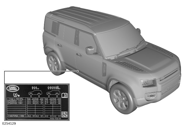
E254129

Engine Serial Numbers

2.0L I4 Diesel Engine
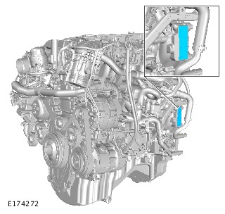
E174272

The engine serial number is visible on the cylinder block.

2.0L I4 Petrol Engine
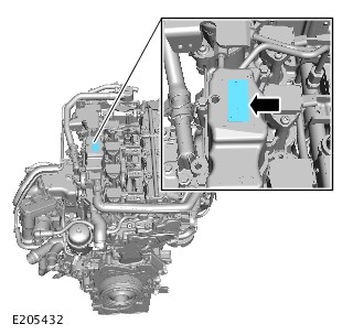
E205432

The engine serial number is visible on the engine vent oil separator.

3.0L I6 Petrol Engine
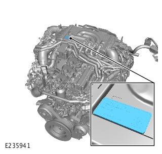
E235941

The engine serial number is visible on the charge air cooler.

3.0L I6 Diesel Engine
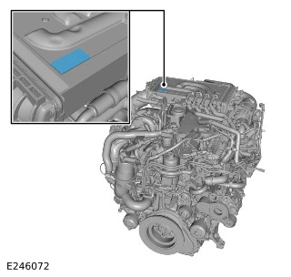
E246072

The engine serial number is visible on the charge air cooler.

5.0L V8 Petrol Engine
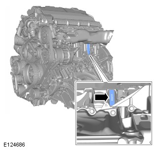
E124686

The engine serial number is visible on the cylinder block.


Software Over The Air Update - Vehicles With: Electrical Vehicle Architecture (EVA) 2 (G2784322)

DESCRIPTION AND OPERATION

CAUTION:

A Software Over The Air (SOTA) Update will not take place if a diagnostic tool is connected to the vehicle.

NOTES:

  • Where possible, an external WiFi connection is preferred.
  • It will not be possible to use an external WiFi connection that requires an authentication Username and Password entering, through a third party webpage for the SOTA update. For example: a guest WiFi connection.
  • The ignition may time out after 10 minutes with the Jaguar Land Rover (JLR) approved battery support unit connected. Consider this when downloading and installing software updates and make sure to switch the ignition back on before a maximum of 30 seconds to resume the process.
  • If a JLR-SST Hand Held Device is available, an application has been included on the tool to hold the ignition on for the duration of the process. This can be launched by connecting the JLR-SST Hand Held Device to the vehicle and following the on-screen instructions.
  • If the process fails or an error message is displayed at any point in the process then a Technical Assistance (TA) must be raised. Select 'SOTA - Update Programming Concern' symptom tag and enter ‘SOTA update error’ in the ‘Customer Concern/Comments’ section of the TA.

1 - Make sure that the vehicle is locked.

2 - Access TOPIx and enter the Vehicle Identification Number (VIN) in the ‘VIN Selection’ box.

3 - Select ‘Fault And breakdown’.

4 - Select the ‘Vehicle Software’ tab.

5 - All available updates for the vehicle will be displayed under the ‘Available Updates’ tab.

Some of these updates could already be applied to the vehicle and queued. These are identifiable by the Update button not being available and greyed out. It is important to note that these queued updates will take precedence over any new updates applied during your session.
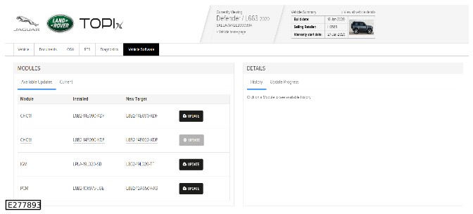
E277893

6 - To view the current software levels in the modules fitted to the vehicle, select the ‘Current’ tab. A module can be selected from the list and will be populated in the right side of the screen.
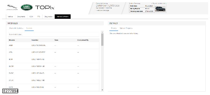
E277894

7 - To complete one of the presented updates, navigate back to the ‘Available updates’ and select the ‘Update’ button next to the required update.

- The update button will turn gray when pressed to indicate the update is now in progress/queued.

8 - Unlock the vehicle.

9 - Connect the JLR approved battery support unit.

10 - Turn the vehicle ignition on or start the vehicle.

11 - Determine the vehicle connectivity method to be used for the SOTA update. The update can be completed using either the vehicles integrated Telematic Control Unit Module (TCU) Subscriber Identification Module (SIM) card, or an external WiFi connection (preferred).

12 - Leave the vehicle with the ignition on, and wait for 3 minutes to allow the vehicle sufficient time to connect with the server. If the vehicle connectivity cannot be established. For additional information, refer to: Software Over The Air Update (SOTA) - Internet Connection (100-12 Software Over The Air, Diagnosis and Testing).

13 - The update will begin automatically when a connection has been established. To view the progress of the update:

- From the TOPIx vehicle software page, select the module which is being updated.

- From the right side of the screen, select Update Progress.

- The screen will not automatically update and requires the refresh button to be pressed to show the latest Update Progress.
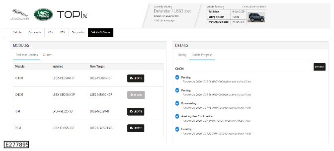
E277895

14 - When the software has been downloaded to the vehicle, the ‘Update Progress’ tab on the TOPIx vehicle software screen will display ‘Awaiting User Confirmation’ for the second time. A popup will also appear on the vehicles touchscreen instructing the user to either ‘Schedule’ the installation or ‘Update’ now.

NOTES:

  • If the TCU software is being updated, there is no popup displayed on the vehicles touchscreen. TOPIx will show the message "Awaiting user confirmation" but the update will automatically get installed.
  • If there is no popup displayed on the vehicles touchscreen it may be necessary to navigate to the software menu in the vehicles touchscreen to view the message.
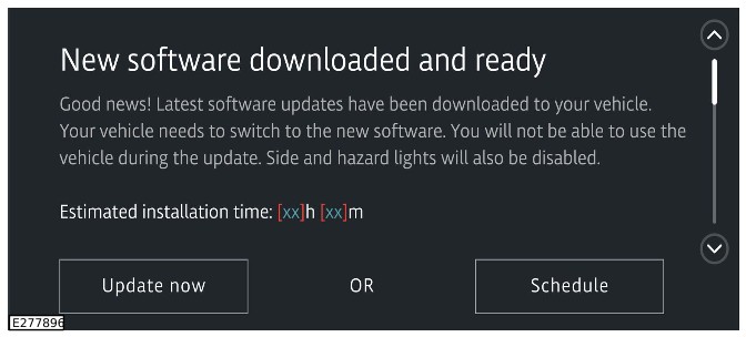
E277896

15 - Select ‘Update now’.

16 - There will now be a message displayed on the vehicles touchscreen detailing the required next steps in order to complete the installation of the new software, and the installation time needed. Make sure that the instructions are read and understood.

17 - Turn the ignition off and lock the vehicle.

18 - Leave the vehicle for the required installation time of the new software.

19 - To view the progress of the installation:

- From the TOPIx vehicle software page, select the module which is being updated.

- From the right side of the screen, select Update Progress.

- The refresh button can be used to refresh the Update Progress.

20 - When the installation of the new software is complete, the ‘Update Progress’ tab on the TOPIx vehicle software screen will display ‘Complete’.

21 - The vehicle can now be unlocked and any further work required can now be completed.

22 - When the TOPIx page is refreshed, the completed update will no longer be shown in the ‘Available Updates’ tab.

23 - To view any SOTA updates that have previously been completed on the vehicle:

- From the TOPIx ‘Vehicle Software’ tab, select the ‘Current’ tab.

- Select a module from the list presented.

- From the right side of the screen select ‘History’.

- All previously completed SOTA updates for the selected module will be displayed along with the update details.
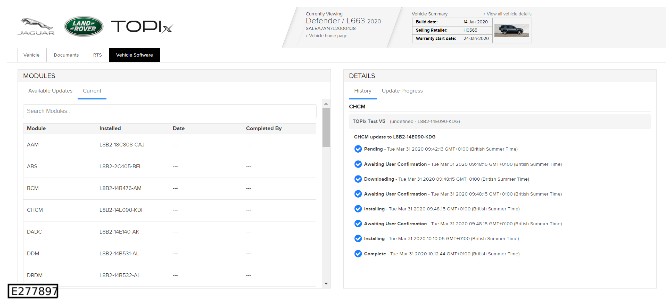
E277897


Software Over The Air

Software Over The Air Update (SOTA) - Internet Connection - PIVI (G3140315)

DIAGNOSIS AND TESTING

SymptomPossible SourcesAction
Internet connectivity not working on the vehicle.
  • Date and time set on the infotainment is not correct.
  • On the infotainment screen go to Home page > Settings > All Settings > General > Time and Date. If the date and time is not correct then set date/time to 'Auto' mode in Home page > Settings > All Settings > General > Time and Date and drive the vehicle to a good known Global Positioning System (GPS) signal location, then confirm the vehicle gets updated with the correct date and time. Confirm the vehicle has good internet connectivity by using any of the following 6 options on the infotainment screen -
    • 1- 4G connection symbol, shown in the side bar.
    • 2 - Traffic on map option navigation.
    • 3 - Up to date weather report is shown when selected from the menu.
    • 4 - Park and pay function should be active (account required). QR code will be present if data connectivity is active.
    • 5 - Audio streaming should be available using Spotify or similar streaming source (account required).
    • 6 - Go to Settings > Mobile Data > Network Provider. IMEI and IMSI reference numbers will be shown on the screen if data connectivity is active.

SymptomPossible SourcesAction
Internet connectivity not working on the vehicle.
  • Internet connection source is not having the internet connectivity.
  • Test 1 - Confirm if the vehicle has good internet connectivity by using any of the following 6 options on the infotainment screen -
    • 1- 4G connection symbol, shown in the side bar.
    • 2 - Traffic on map option navigation.
    • 3 - Up to date weather report is shown when selected from the menu.
    • 4 - Park and pay function should be active (account required). QR code will be present if data connectivity is active.
    • 5 - Audio streaming should be available using Spotify or similar streaming source (account required).
    • 6 - Go to Settings > Mobile Data > Network Provider. IMEI and IMSI reference numbers will be shown on the screen if data connectivity is active.
  • Test 2 - Connect a mobile phone to the same internet source and check on the mobile phone if the internet can be accessed.

Integrated Air Compressor (G2893419)

DIAGNOSIS AND TESTING

Principles of Operation

For a detailed description of the Integrated Air Compressor system, refer to the relevant Accessory Information section in the workshop manual. REFER to: Integrated Air Compressor - 90/110 (102-02 Interior, Removal and Installation).

Inspection and Verification

CAUTION:

Diagnosis by substitution from a donor vehicle is NOT acceptable. Substitution of control modules does not guarantee confirmation of a fault, and may also cause additional faults in the vehicle being tested and/or the donor vehicle.

NOTES:

  • If a control module or a component is at fault of may be at fault and the vehicle remains under manufacturer warranty, refer to the Warranty Policy and Procedures manual, or determine if any prior approval program is in operation, prior to the installation of a new module/component.
  • When performing voltage or resistance tests, always use a digital multimeter accurate to three decimal places, and with an up-to-date calibration certificate. When testing resistance always take the resistance of the digital multimeter leads into account.
  • Check and rectify basic faults before beginning diagnostic routines involving pinpoint tests.
  1. Verify the customer concern
  1. Complete the air compressor software update procedure REFER to: Integrated Air Compressor Software Update (102-02 Interior, General Procedures).
  1. Visually inspect for obvious signs of damage and system integrity
  1. If an obvious cause for an observed or reported concern is found, correct the cause (if possible) before proceeding to the next step
  1. If the cause is not visually evident, verify the symptoms and check for error codes on the integrated air compressor display
  1. Check the JLR claims submission system for open campaigns. Refer to the corresponding bulletins and SSMs which may be valid for the specific customer complaint and complete the recommendations as required.

Symptom Chart

SymptomPossible CausesAction
Integrated air compressor/Display does not turn on
  • Wiring/connector
  • Integrated air compressor software fault
NOTE:

The integrated air compressor is only operational with the ignition switched on and the engine running

  • GO to Pinpoint Test G.
Error code "E1" showing on integrated air compressor display. (E1 = Over pressure, Integrated air compressor system detects over pressure (>80 PSI) value from the pressure sensor)
  • Blocked airlines
  • Wiring/connector
  • Pressure sensor fault
  • Integrated air compressor Electronic Control Unit (ECU) fault
NOTE:

Automatic deflation until 80 PSI is reached

  • GO to Pinpoint Test A.
Error code "E2" showing on integrated air compressor display (E2 = No sensor signal, pressure sensor signal is not available)
  • Wiring/connector
  • Pressure sensor fault
  • GO to Pinpoint Test B.
Error code "E3" showing on integrated air compressor display (E3 = Compressor overheating detected by the temperature switch, disabling the temperature switch input/Temperature in the compressor motor reached 105°C)
  • Wiring/connector
  • Temperature switch
  • Blocked air filter
  • GO to Pinpoint Test C.
Error code "E4" showing on integrated air compressor display (E4 = Unexpected pressure signal received on the pressure signal input)
  • Blocked airlines
  • Air leak
  • Wiring/connector
  • Pressure sensor fault
  • Integrated air compressor software fault
  • Integrated air compressor ECU fault
  • GO to Pinpoint Test D.
Error code "E5" showing on integrated air compressor display (E5 = Over voltage (>17 volts) detected on power input, outputs switched off to protect components until the power supply returns to the operational voltage range of 8 - 17 volts)
  • Wiring/connector
  • Integrated air compressor ECU fault
  • GO to Pinpoint Test E.
Error code "E6" showing on integrated air compressor display (E6 = Under voltage (<8 volts) detected on power input, outputs switched off to protect components until the power supply returns to the operational voltage range of 8 - 17 volts)
  • Wiring/connector
  • Integrated air compressor ECU fault
  • Integrated air compressor software fault
  • GO to Pinpoint Test F.
High pressure - In "ON" (flat tire mode) the pressure monitoring system is turned OFF to provide continuous inflation. The high pressure protection is still active
  • Blocked airlines
  • Wiring/connector
  • Pressure sensor fault
  • Integrated air compressor ECU fault
  • GO to Pinpoint Test H.

E270851

The image above shows the integrated air compressor display.

Pinpoint Tests

PINPOINT TEST A : ERROR CODE "E1" SHOWING ON INTEGRATED AIR COMPRESSOR DISPLAY
A1: CHECK AIR LINES FOR BLOCKAGES
TEST CONDITIONSDETAILS/RESULTS/ACTIONS
1 The internal airlines could be blocked, make sure that the airlines are clear by checking for air exiting the outlet.
Are the airlines blocked? Yes Unblock the airlines and retest the system. No GO to A2.
A2: WIRING HARNESS/CONNECTOR INTEGRITY CHECKS
TEST CONDITIONSDETAILS/RESULTS/ACTIONS
E270852 1 Refer to the image and check the 3 pin connector 4 is secure and fully latched at the compressor ECU, check the connector for any damaged, loose or bent pins.
Were any concerns identified with the connector 4? Yes Repair the connector as necessary and retest the system. No GO to A3.
A3: WIRING HARNESS/CONNECTOR INTEGRITY CHECKS
TEST CONDITIONSDETAILS/RESULTS/ACTIONS
E270853 1 Refer to the image and check the 3 pin connector 5 is secure and fully latched at the pressure sensor, check the connector for any damaged, loose or bent pins.
Were any concerns identified with the connector 5? Yes Repair the connector as necessary and retest the system. No GO to A4.
A4: WIRING HARNESS/CONNECTOR INTEGRITY CHECKS
TEST CONDITIONSDETAILS/RESULTS/ACTIONS
1 Check for any damage to the wiring harness between the ECU and the pressure sensor
Was any damage to the wiring harness identified? Yes Repair the wiring harness as necessary and retest the system. No GO to A5.
A5: WIRING HARNESS/CONNECTOR INTEGRITY CHECKS
TEST CONDITIONSDETAILS/RESULTS/ACTIONS
1 Disconnect and reconnect connectors 4 and 5 and retest the system
Does the system operate correctly? Yes No further action required No If the E1 error code persists, install a new integrated air compressor as necessary and retest the system.
PINPOINT TEST B : ERROR CODE "E2" SHOWING ON INTEGRATED AIR COMPRESSOR DISPLAY
B1: WIRING HARNESS/CONNECTOR INTEGRITY CHECKS
TEST CONDITIONSDETAILS/RESULTS/ACTIONS
E270852 1 Refer to the image and check the 3 pin connector 4 is secure and fully latched at the compressor ECU, check the connector for any damaged, loose or bent pins.
Were any concerns identified with the connector 4? Yes Repair the connector as necessary and retest the system. No GO to B2.
B2: WIRING HARNESS/CONNECTOR INTEGRITY CHECKS
TEST CONDITIONSDETAILS/RESULTS/ACTIONS
E270853 1 Refer to the image and check the 3 pin connector 5 is secure and fully latched at the pressure sensor, check the connector for any damaged, loose or bent pins.
Were any concerns identified with the connector 5? Yes Repair the connector as necessary and retest the system. No GO to B3.
B3: WIRING HARNESS/CONNECTOR INTEGRITY CHECKS
TEST CONDITIONSDETAILS/RESULTS/ACTIONS
1 Check for any damage to the wiring harness between the ECU and the pressure sensor
Was any damage to the wiring harness identified? Yes Repair the wiring harness as necessary and retest the system. No GO to B4.
B4: WIRING HARNESS/CONNECTOR INTEGRITY CHECKS
TEST CONDITIONSDETAILS/RESULTS/ACTIONS
1 Disconnect and reconnect connectors 4 and 5 and retest the system
Does the system operate correctly? Yes No further action required No If the E2 error code persists, install a new integrated air compressor as necessary and retest the system.
PINPOINT TEST C : ERROR CODE "E3" SHOWING ON INTEGRATED AIR COMPRESSOR DISPLAY
C1: WIRING HARNESS/CONNECTOR INTEGRITY CHECKS
TEST CONDITIONSDETAILS/RESULTS/ACTIONS
E270852 1 Refer to the image and check the 5 pin connector 1 is secure and fully latched at the compressor ECU, check the connector for any damaged, loose or bent pins.
Were any concerns identified with the connector 1? Yes Repair the connector as necessary and retest the system. No GO to C2.
C2: CHECK COMPRESSOR AIR FILTER FOR BLOCKAGE
TEST CONDITIONSDETAILS/RESULTS/ACTIONS
E281826 1 Check the air filter located at the bottom of the compressor, remove the air filter cover and check the air filter for any blockages.
Was the compressor air filter found to be blocked? Yes Clean the compressor air filter as necessary and retest the system. No GO to C3.
C3: WIRING HARNESS/CONNECTOR INTEGRITY CHECKS
TEST CONDITIONSDETAILS/RESULTS/ACTIONS
1 Disconnect and reconnect connector 1 and retest the system
Does the system operate correctly? Yes No further action required No If the E3 error code persists, install a new integrated air compressor as necessary and retest the system.
PINPOINT TEST D : ERROR CODE "E4" SHOWING ON INTEGRATED AIR COMPRESSOR DISPLAY
D1: CHECK AIR LINES FOR LEAKS OR BLOCKAGES
TEST CONDITIONSDETAILS/RESULTS/ACTIONS
1 The internal airlines could be blocked or leaking, make sure that the airlines are clear by checking for air exiting the outlet.
Are the airlines blocked? Yes Unblock the airlines and retest the system. No GO to D2.
D2: CHECK AIR LINES FOR LEAKS OR BLOCKAGES
TEST CONDITIONSDETAILS/RESULTS/ACTIONS
1 Check for leaks by blocking the outlet and running the compressor, listen and check for any leaks
Were any leaks identified? Yes Rectify leaks as necessary and retest the system. No GO to D3.
D3: CHECK THE SOLENOID VALVE FOR LEAKS
TEST CONDITIONSDETAILS/RESULTS/ACTIONS
1 Without the compressor operating, connect the hose to a tire valve and check the solenoid valve for leaks by listening for air leaking from the solenoid valve.
Were any leaks identified from the solenoid valve? Yes Rectify leaks as necessary and retest the system. No GO to D4.
D4: WIRING HARNESS/CONNECTOR INTEGRITY CHECKS
TEST CONDITIONSDETAILS/RESULTS/ACTIONS
E270852 1 Refer to the image and check the 3 pin main power connector 2 is secure and fully latched at the compressor ECU, check the connector for any damaged, loose or bent pins.
Were any concerns identified with the connector 2? Yes Repair the connector as necessary and retest the system. No GO to D5.
D5: WIRING HARNESS/CONNECTOR INTEGRITY CHECKS
TEST CONDITIONSDETAILS/RESULTS/ACTIONS
E270852 1 Refer to the image and check the 3pin sensor connector 4 is secure and fully latched at the compressor ECU, check the connector for any damaged, loose or bent pins.
Were any concerns identified with the connector 4? Yes Repair the connector as necessary and retest the system. No GO to D6.
D6: WIRING HARNESS/CONNECTOR INTEGRITY CHECKS
TEST CONDITIONSDETAILS/RESULTS/ACTIONS
1 Refer to the image and check the 3 pin connector 5 is secure and fully latched at the pressure sensor, check the connector for any damaged, loose or bent pins.
Were any concerns identified with the connector 5? Yes Repair the connector as necessary and retest the system. No GO to D7.
D7: WIRING HARNESS/CONNECTOR INTEGRITY CHECKS
TEST CONDITIONSDETAILS/RESULTS/ACTIONS
1 Check for any damage to the wiring harness between the ECU and the pressure sensor.
Was any damage to the wiring harness identified? Yes Repair the wiring harness as necessary and retest the system. No GO to D8.
D8: WIRING HARNESS/CONNECTOR INTEGRITY CHECKS
TEST CONDITIONSDETAILS/RESULTS/ACTIONS
1 Disconnect and reconnect connectors 2, 4 and 5 and retest the system.
Does the system operate correctly? Yes No further action required. No If the E4 error code persists, complete the air compressor software update procedure REFER to: Integrated Air Compressor Software Update (102-02 Interior, General Procedures). Retest the system. If the E4 error code persists, install a new integrated air compressor as necessary and retest the system.
PINPOINT TEST E : ERROR CODE "E5" SHOWING ON INTEGRATED AIR COMPRESSOR DISPLAY
E1: VOLTAGE CHECKS
TEST CONDITIONSDETAILS/RESULTS/ACTIONS
NOTE:

Outputs will be switched off if the voltage detected is greater than 17 volts, the operational voltage is 8 - 17 volts

E270852 1 Refer to the image and measure the input voltage on the 3 pin power input connector 2
Is the voltage less than 17 volts and within the operational voltage of 8 - 17 volts? Yes If the E5 error code persists, install a new integrated air compressor as necessary and retest the system. No Continue with further diagnosis with the vehicle electrical system to find the cause of the high voltage.
PINPOINT TEST F : ERROR CODE "E6" SHOWING ON INTEGRATED AIR COMPRESSOR DISPLAY
F1: VOLTAGE CHECKS
TEST CONDITIONSDETAILS/RESULTS/ACTIONS
NOTE:

Outputs will be switched off if the voltage detected is less that 8 volts, the operational voltage is 8 - 17 volts

E270852 1 Refer to the image and measure the input voltage on the 3 pin power input connector 2
Is the voltage less than 8 volts? Yes GO to F2. No GO to F2.
F2: VOLTAGE CHECKS
TEST CONDITIONSDETAILS/RESULTS/ACTIONS
1 Measure the voltage at the power outlet connector and at the fuse of the power outlet connector
Is the voltage less than 8 volts? Yes Continue with further diagnosis with the vehicle electrical system to find the cause of the low voltage. No GO to F3.
F3: WIRING HARNESS/CONNECTOR INTEGRITY CHECKS
TEST CONDITIONSDETAILS/RESULTS/ACTIONS
1 If the voltage is lower than 8 volts at the 3 pin power input connector (2) but the voltage is higher than 8 volts at the power outlet connector, check the wiring harness for any damage. The fault can be caused by a higher-than-normal resistance in the wiring of the compressor. The compressor is powered from the cigar lighter feed. Refer to the circuit diagrams for the cigar lighter feed and check for faulty connectors.
Was any damage to the wiring harness identified? Yes Repair the wiring harness as necessary and retest the system. No If the voltage is above 8 volts at the 3 pin power input connector 2 and within the operational voltage range of 8 - 17 volts, complete the air compressor software update procedure REFER to: Integrated Air Compressor Software Update (102-02 Interior, General Procedures). Retest the system. If the fault persists, install a new integrated air compressor as necessary and retest they system.
PINPOINT TEST G : INTEGRATED AIR COMPRESSOR/DISPLAY DOES NOT TURN ON
G1: WIRING HARNESS/CONNECTOR INTEGRITY CHECKS
TEST CONDITIONSDETAILS/RESULTS/ACTIONS
NOTE:

It is recommended that the air compressor is only operated with the engine running to make sure there is consistent power to the air compressor and to avoid vehicle battery discharge

E270852 1 Refer to the image and check the 3 pin main power connector 2 is secure and fully latched at the compressor ECU, check the connector for any damaged, loose or bent pins.
Were any concerns identified with the connector 2? Yes Repair the connector as necessary and retest the system. No GO to G2.
G2: VOLTAGE CHECKS
TEST CONDITIONSDETAILS/RESULTS/ACTIONS
E270852 1 Refer to the image and check the 10pin connector 3 is secure and fully latched at the compressor ECU, check the connector for any damaged, loose or bent pins.
2 Measure the voltage on the power (brown) and ground (black) wires of the 3 pin main power connector 2
Is the voltage within the operational voltage range of 8 - 17 volts? Yes If no other faults are found and the fault persists, install a new integrated air compressor as necessary and retest the system. No GO to G3.
G3: WIRING HARNESS/CONNECTOR INTEGRITY CHECKS
TEST CONDITIONSDETAILS/RESULTS/ACTIONS
E270857 1 Refer to the image and check the 2 pin main power connector 6 is secure and fully latched at the mating connector, check the connector for any damaged, loose or bent pins.
Were any concerns identified with the connector 6? Yes Repair the connector as necessary and retest the system. No GO to G4.
G4: VEHICLE ACCESSORY SOCKET VOLTAGE CHECKS
TEST CONDITIONSDETAILS/RESULTS/ACTIONS
1 Check the voltage at the vehicle accessory socket connectors and check the fuse for the accessory socket located in the rear loadspace junction box.
Were any concerns found with the vehicle accessory socket? Yes Repair as necessary, complete the air compressor software update procedure REFER to: Integrated Air Compressor Software Update (102-02 Interior, General Procedures). Retest the system. No Check the wiring between the accessory socket and the compressor ECU, repair as necessary, complete the air compressor software update procedure REFER to: Integrated Air Compressor Software Update (102-02 Interior, General Procedures). Retest the system.
PINPOINT TEST H : HIGH PRESSURE PROTECTION STILL ACTIVE
H1: CHECK AIR LINES FOR BLOCKAGES
TEST CONDITIONSDETAILS/RESULTS/ACTIONS
1 The internal airlines could be blocked, make sure that the airlines are clear by checking for air exiting the outlet.
Are the airlines blocked? Yes Unblock the airlines and retest the system. No GO to H2.
H2: WIRING HARNESS/CONNECTOR INTEGRITY CHECKS
TEST CONDITIONSDETAILS/RESULTS/ACTIONS
E270852 1 Refer to the image and check the 3 pin connector 4 is secure and fully latched at the compressor ECU, check the connector for any damaged, loose or bent pins.
Were any concerns identified with the connector 4? Yes Repair the connector as necessary and retest the system. No GO to H3.
H3: WIRING HARNESS/CONNECTOR INTEGRITY CHECKS
TEST CONDITIONSDETAILS/RESULTS/ACTIONS
1 Refer to the image and check the 3 pin connector 5 is secure and fully latched at the pressure sensor, check the connector for any damaged, loose or bent pins.
Were any concerns identified with the connector 5? Yes Repair the connector as necessary and retest the system. No GO to H4.
H4: WIRING HARNESS/CONNECTOR INTEGRITY CHECKS
TEST CONDITIONSDETAILS/RESULTS/ACTIONS
1 Check for any damage to the wiring harness between the ECU and the pressure sensor
Was any damage to the wiring harness identified? Yes Repair the wiring harness as necessary and retest the system. No GO to H5.
H5: WIRING HARNESS/CONNECTOR INTEGRITY CHECKS
TEST CONDITIONSDETAILS/RESULTS/ACTIONS
1 Disconnect and reconnect connectors 4 and 5 and retest the system
Does the system operate correctly? Yes No further action required No If the fault persists, install a new integrated air compressor as necessary and retest the system.


Suspension System - General Information (G3206109)

SPECIFICATIONS

Ride Height - 90

ItemSpecificationSpecification
* Nominal heights from hub centre to underside of wheel arch (not liner):Air spring suspensionCoil spring suspension
Front510 ± 12 mm (20.08 ± 0.47 in)518 ± 12 mm (20.39 ± 0.47 in)
Rear521 ± 13 mm (20.51 ± 0.51 in)530 ± 13 mm (20.87 ± 0.51 in)

* Measurement taken with vehicle at unladen weight

Wheel Alignment Specification - Front - Coil Spring Suspension - 90

NOTE:

All figures are with vehicle at 'Showroom' ride height - full fluids, full tank of fuel, no occupants/luggage, tires inflated to normal pressures

Item Left SideRight SideTotal/Balance
Camber NominalToleranceNominalToleranceNominalTolerance
 Decimal degrees-0.43°± 0.75°-0.43°± 0.75°0.0°± 0.75°
 Degrees/minutes-25' 48''± 45'-25' 48''± 45'0'± 45'
  MinimumMaximumMinimumMaximumMinimumMaximum
 Decimal degrees-1.18°0.32°-1.18°0.32°-0.75°0.75°
 Degrees/minutes-1°10'48''19'12''-1°10'48''19'12''-45'45'
Castor NominalToleranceNominalToleranceNominalTolerance
 Decimal degrees3.85°± 0.75°3.85°± 0.75°0.0°± 0.75°
 Degrees/minutes3°51'± 45'3°51'± 45'0'± 45'
  MinimumMaximumMinimumMaximumMinimumMaximum
 Decimal degrees3.10°4.60°3.10°4.60°-0.75°0.75°
 Degrees/minutes3°6'4°36'3°6'4°36'-45'45'
Toe     NominalTolerance
 Decimal degrees    0.28°± 0.14°
 Degrees/minutes    16'48''± 8'24''
      MinimumMaximum
 Decimal degrees    0.14°0.42°
 Degrees/minutes    8'24''25'12''

Wheel Alignment Specification - Front - Air Spring Suspension - 90

NOTE:

All figures are with vehicle at 'Showroom' ride height - full fluids, full tank of fuel, no occupants/luggage, tires inflated to normal pressures

Item Left SideRight SideTotal/Balance
Camber NominalToleranceNominalToleranceNominalTolerance
 Decimal degrees-0.60°± 0.75°-0.60°± 0.75°0.0°± 0.75°
 Degrees/minutes-0.36'± 45'-0.36'± 45'0'± 45'
  MinimumMaximumMinimumMaximumMinimumMaximum
 Decimal degrees-1.35°0.15°-1.35°0.15°-0.75°0.75°
 Degrees/minutes-1°21'9'-1°21'9'-45'45'
Castor NominalToleranceNominalToleranceNominalTolerance
 Decimal degrees4.02°± 0.75°4.02°± 0.75°0.0°± 0.75°
 Degrees/minutes4°1'12''± 45'4°1'12'± 45'0'± 45'
  MinimumMaximumMinimumMaximumMinimumMaximum
 Decimal degrees3.27°4.77°3.27°4.77°-0.75°0.75°
 Degrees/minutes3°16'12''4°46'12''3°16'12''4°46'12''-45'45'
Toe     NominalTolerance
 Decimal degrees    0.26°± 0.14°
 Degrees/minutes    15'36''± 8'24''
      MinimumMaximum
 Decimal degrees    0.12°0.40°
 Degrees/minutes    7'12''24'

Wheel Alignment Specification - Rear - Coil Spring Suspension - 90

NOTE:

All figures are with vehicle at 'Showroom' ride height - full fluids, full tank of fuel, no occupants/luggage, tires inflated to normal pressures

Item Left SideRight SideTotal/BalanceThrust Angle
Camber NominalToleranceNominalToleranceNominalToleranceNominalTolerance
 Decimal degrees-1.33°± 0.75°-1.33°± 0.75°0.0°± 0.75°0.0°± 0.07°
 Degrees/minutes-1°19'48''± 45'-1°19'48''± 45'0°0'± 45'0'± 4'12''
  MinimumMaximumMinimumMaximumMinimumMaximumMinimumMaximum
 Decimal degrees-2.08°-0.58°-2.08°-0.58°-0.75°0.75°-0.07°0.07°
 Degrees/minutes-2°4'48''-34'48''-2°4'48''-34'48''-45'45'-4'12''4'12''
Toe NominalToleranceNominalToleranceNominalTolerance  
 Decimal degrees0.12°± 0.10°0.12°± 0.10°0.24°± 0.14°  
 Degrees/minutes7'12''± 6'7'12''± 6'14'24''± 8'24''  
  MinimumMaximumMinimumMaximumMinimumMaximum  
 Decimal degrees0.02°0.22°0.02°0.22°0.10°0.38°  
 Degrees/minutes1'12''13'12''1'12''13'12''6'22'48''  

Wheel Alignment Specification - Rear - Air Spring Suspension - 90

NOTE:

All figures are with vehicle at 'Showroom' ride height - full fluids, full tank of fuel, no occupants/luggage, tires inflated to normal pressures

Item Left SideRight SideTotal/BalanceThrust Angle
Camber NominalToleranceNominalToleranceNominalToleranceNominalTolerance
 Decimal degrees-1.48°± 0.75°-1.48°± 0.75°0.0°± 0.75°0.0°± 0.07°
 Degrees/minutes-1°28'48''± 45'-1°28'48''± 45'0'± 45'0'± 4'12''
  MinimumMaximumMinimumMaximumMinimumMaximumMinimumMaximum
 Decimal degrees-2.23°-0.73°-2.23°-0.73°-0.75°0.75°-0.07°0.07°
 Degrees/minutes-2°13'48''-43'48''-2°13'48''-43'48''-45'45'-4'12''4'12''
Toe NominalToleranceNominalToleranceNominalTolerance  
 Decimal degrees0.13°± 0.10°0.13°± 0.10°0.26°± 0.14°  
 Degrees/minutes7'48''± 6'7'48''± 6'15'36''± 8'24''  
  MinimumMaximumMinimumMaximumMinimumMaximum  
 Decimal degrees0.03°0.23°0.03°0.23°0.12°0.40°  
 Degrees/minutes1'48''13'48''1'48''13'48''7'12''24'  

Ride Height - 110

ItemSpecification
* Nominal heights from hub centre to underside of wheel arch (not liner):Air spring suspensionCoil spring suspensionOCTA suspension
Front509 ± 12 mm (20.04 ± 0.47 in)520 ± 12 mm (20.47 ± 0.47 in)526 ± 12 mm (20.71 ± 0.47 in)
Rear520 ± 13 mm (20.47 ± 0.51 in)527 ± 13 mm (20.75 ± 0.51 in)541 ± 13 mm (21.30 ± 0.51 in)

* Measurement taken with vehicle at unladen weight

Wheel Alignment Specification - Front - Air Spring Suspension - 110

NOTE:

All figures are with vehicle at 'Showroom' ride height - full fluids, full tank of fuel, no occupants/luggage, tires inflated to normal pressures

Item Left SideRight SideTotal/Balance
Camber NominalToleranceNominalToleranceNominalTolerance
 Decimal degrees-0.61°± 0.75°-0.61°± 0.75°0.0°± 0.75°
 Degrees/minutes-36'36''± 45'-36'36''± 45'0'± 45'
  MinimumMaximumMinimumMaximumMinimumMaximum
 Decimal degrees-1.36°0.14°-1.36°0.14°-0.75°0.75°
 Degrees/minutes-1°21'36''8'24''-1°21'36''8'24''-45'45'
Castor NominalToleranceNominalToleranceNominalTolerance
 Decimal degrees4.02°± 0.75°4.02°± 0.75°0.0°± 0.75°
 Degrees/minutes4°1'12''± 45'4°1'12''± 45'0'± 45'
  MinimumMaximumMinimumMaximumMinimumMaximum
 Decimal degrees3.27°4.77°3.27°4.77°-0.75°0.75°
 Degrees/minutes3°16'12''4°46'12''3°16'12''4°46'12''-45'45'
Toe     NominalTolerance
 Decimal degrees    0.26°± 0.14°
 Degrees/minutes    15'36''8'24''
      MinimumMaximum
 Decimal degrees    0.12°0.40°
 Degrees/minutes    7'12''24'

Wheel Alignment Specification - Front - Coil Spring Suspension - 110

NOTE:

All figures are with vehicle at 'Showroom' ride height - full fluids, full tank of fuel, no occupants/luggage, tires inflated to normal pressures

Item Left SideRight SideTotal/Balance
Camber NominalToleranceNominalToleranceNominalTolerance
 Decimal degrees-0.40°± 0.75°-0.40°± 0.75°0.0°± 0.75°
 Degrees/minutes-24'± 45'-24'± 45'0'± 45'
  MinimumMaximumMinimumMaximumMinimumMaximum
 Decimal degrees-1.15°0.35°-1.15°0.35°-0.75°0.75°
 Degrees/minutes-1°9'21'-1°9'21'-45'45'
Castor NominalToleranceNominalToleranceNominalTolerance
 Decimal degrees3.88°± 0.75°3.88°± 0.75°0.0°± 0.75°
 Degrees/minutes3°52'48''± 45'3°52'48''± 45'0'± 45'
  MinimumMaximumMinimumMaximumMinimumMaximum
 Decimal degrees3.13°4.63°3.13°4.63°-0.75°0.75°
 Degrees/minutes3°7'48''4°37'48''3°7'48''4°37'48''-45'45'
Toe     NominalTolerance
 Decimal degrees    0.31°± 0.14°
 Degrees/minutes    18'36''± 8'24''
      MinimumMaximum
 Decimal degrees    0.17°0.45°
 Degrees/minutes    10'12''27'

Wheel Alignment Specification - Front - Air Spring Suspension - 110 - OCTA

NOTE:

All figures are with vehicle at 'Showroom' ride height - full fluids, full tank of fuel, no occupants/luggage, tires inflated to normal pressures

Item Left SideRight SideTotal/Balance
Camber NominalToleranceNominalToleranceNominalTolerance
 Decimal degrees-0.58°± 0.75°-0.58°± 0.75°0.0°± 0.75°
 Degrees/minutes-34'48''± 45'-34'48''± 45'0'± 45'
  MinimumMaximumMinimumMaximumMinimumMaximum
 Decimal degrees-1.33°0.17°-1.33°0.17°-0.75°0.75°
 Degrees/minutes-1°19'48''10'12''-1°19'48''10'12''-45'45'
Castor NominalToleranceNominalToleranceNominalTolerance
 Decimal degrees4.30°± 0.75°4.30°± 0.75°0.0°± 0.90°
 Degrees/minutes4°18''± 45'4°18''± 45'0'± 54'
  MinimumMaximumMinimumMaximumMinimumMaximum
 Decimal degrees3.55°5.05°3.55°5.05°-0.90°0.90°
 Degrees/minutes3°33'5°03'3°33'5°03'-54'54'
Toe     NominalTolerance
 Decimal degrees    0.23°± 0.14°
 Degrees/minutes    13'48''± 8'24''
      MinimumMaximum
 Decimal degrees    0.09°0.37°
 Degrees/minutes    5'24''22'12''

Wheel Alignment Specification - Rear - Air Spring Suspension - 110

NOTE:

All figures are with vehicle at 'Showroom' ride height - full fluids, full tank of fuel, no occupants/luggage, tires inflated to normal pressures

Item Left SideRight SideTotal/BalanceThrust Angle
Camber NominalToleranceNominalToleranceNominalToleranceNominalTolerance
 Decimal degrees-1.48°± 0.75°-1.48°± 0.75°0.0°± 0.75°± 0.07°
 Degrees/minutes-1°28'48''± 45'-1°28'48''± 45'0'± 45'0'± 4'12''
  MinimumMaximumMinimumMaximumMinimumMaximumMinimumMaximum
 Decimal degrees-2.23°-0.73°-2.23°-0.73°-0.75°0.75°-0.07°0.07°
 Degrees/minutes-2°13'48''-43'48''-2°13'48''-43'48''-45'45'-4'12''4'12''
Toe NominalToleranceNominalToleranceNominalTolerance  
 Decimal degrees0.13°± 0.10°0.13°± 0.10°0.26°± 0.14°  
 Degrees/minutes7'48''± 6'7'48''± 6'15'36''± 8'24''  
  MinimumMaximumMinimumMaximumMinimumMaximum  
 Decimal degrees0.03°0.23°0.03°0.23°0.12°0.40°  
 Degrees/minutes1'48''13'48''1'48''13'48''7'12''24'  

Wheel Alignment Specification - Rear - Coil Spring Suspension - 110

NOTE:

All figures are with vehicle at 'Showroom' ride height - full fluids, full tank of fuel, no occupants/luggage, tires inflated to normal pressures

Item Left SideRight SideTotal/BalanceThrust Angle
Camber NominalToleranceNominalToleranceNominalToleranceNominalTolerance
 Decimal degrees-1.33°± 0.75°-1.33°± 0.75°0.0°± 0.75°± 0.07°
 Degrees/minutes-1°19'48''± 45'-1°19'48''± 45'0'± 45'0'± 4'12''
  MinimumMaximumMinimumMaximumMinimumMaximumMinimumMaximum
 Decimal degrees-2.08°-0.58°-2.08°-0.58°-0.75°0.75°-0.07°0.07°
 Degrees/minutes-2°4'48''-34'48''-2°4'48''-34'48''-45'45'-4'12''4'12''
Toe NominalToleranceNominalToleranceNominalTolerance  
 Decimal degrees0.12°± 0.10°0.12°± 0.10°0.24°± 0.14°  
 Degrees/minutes7'12''± 6'7'12''± 6'14'24''± 8'24''  
  MinimumMaximumMinimumMaximumMinimumMaximum  
 Decimal degrees0.02°0.22°0.02°0.22°0.10°0.38°  
 Degrees/minutes1'12''13'12''1'12''13'12''6'22'48''  

Wheel Alignment Specification - Rear - Air Spring Suspension - 110 - OCTA

NOTE:

All figures are with vehicle at 'Showroom' ride height - full fluids, full tank of fuel, no occupants/luggage, tires inflated to normal pressures

Item Left SideRight SideTotal/BalanceThrust Angle
Camber NominalToleranceNominalToleranceNominalToleranceNominalTolerance
 Decimal degrees-1.72°± 0.75°-1.72°± 0.75°0.0°± 0.75°± 0.07°
 Degrees/minutes-1°43'12''± 45'-1°43'12''± 45'0'± 45'0'± 4'12''
  MinimumMaximumMinimumMaximumMinimumMaximumMinimumMaximum
 Decimal degrees-2.47°-0.97°-2.47°-0.97°-0.75°0.75°-0.07°0.07°
 Degrees/minutes-2°28'12''-58'12''-2°28'12''-58'12''-45'45'-4'12''4'12''
Toe NominalToleranceNominalToleranceNominalTolerance  
 Decimal degrees0.13°± 0.10°0.13°± 0.10°0.25°± 0.14°  
 Degrees/minutes7'48''± 6'7'48''± 6'15'± 8'24''  
  MinimumMaximumMinimumMaximumMinimumMaximum  
 Decimal degrees0.03°0.23°0.03°0.23°0.11°0.39°  
 Degrees/minutes1'48''13'48''1'48''13'48''6'36'''23'24''  

Ride Height - 130

ItemSpecification
* Nominal heights from hub centre to underside of wheel arch (not liner):Air spring suspension
Front509 ± 12 mm (20.04 ± 0.47 in)
Rear521 ± 13 mm (20.51 ± 0.51 in)

* Measurement taken with vehicle at unladen weight

Wheel Alignment Specification - Front - Air Spring Suspension - 130

NOTE:

All figures are with vehicle at 'Showroom' ride height - full fluids, full tank of fuel, no occupants/luggage, tires inflated to normal pressures

Item Left SideRight SideTotal/Balance
Camber NominalToleranceNominalToleranceNominalTolerance
 Decimal degrees-0.61°± 0.75°-0.61°± 0.75°0.0°± 0.75°
 Degrees/minutes-36'36''± 45'-36'36''± 45'0'± 45'
  MinimumMaximumMinimumMaximumMinimumMaximum
 Decimal degrees-1.36°0.14°-1.36°0.14°-0.75°0.75°
 Degrees/minutes-1°21'36''8'24''-1°21'36''8'24''-45'45'
Castor NominalToleranceNominalToleranceNominalTolerance
 Decimal degrees4.01°± 0.75°4.01°± 0.75°0.0°± 0.75°
 Degrees/minutes4°0'36''± 45'4°0'36''± 45'0'± 45'
  MinimumMaximumMinimumMaximumMinimumMaximum
 Decimal degrees3.26°4.76°3.26°4.76°-0.75°0.75°
 Degrees/minutes3°15'36''4°45'36''3°15'36''4°45'36''-45'45'
Toe     NominalTolerance
 Decimal degrees    0.26°± 0.14°
 Degrees/minutes    15'36''± 8'24''
      MinimumMaximum
 Decimal degrees    0.12°0.40°
 Degrees/minutes    7'12''24'

Wheel Alignment Specification - Rear - Air Spring Suspension - 130

NOTE:

All figures are with vehicle at 'Showroom' ride height - full fluids, full tank of fuel, no occupants/luggage, tires inflated to normal pressures

Item Left SideRight SideTotal/BalanceThrust Angle
Camber NominalToleranceNominalToleranceNominalToleranceNominalTolerance
 Decimal degrees-1.48°± 0.75°-1.48°± 0.75°0.0°± 0.75°± 0.07°
 Degrees/minutes-1°28'48''± 45'-1°28'48''± 45'0'± 45'0'± 4'12''
  MinimumMaximumMinimumMaximumMinimumMaximumMinimumMaximum
 Decimal degrees-2.23°-0.73°-2.23°-0.73°-0.75°0.75°-0.07°0.07°
 Degrees/minutes-2°13'48''-43'48''-2°13'48''-43'48''-45'45'-4'12''4'12''
Toe NominalToleranceNominalToleranceNominalTolerance  
 Decimal degrees0.13°± 0.10°0.13°± 0.10°0.26°± 0.14°  
 Degrees/minutes7'48''± 6'7'48''± 6'15'36''± 8'24''  
  MinimumMaximumMinimumMaximumMinimumMaximum  
 Decimal degrees0.03°0.23°0.03°0.23°0.12°0.40°  
 Degrees/minutes1'48''13'48''1'48''13'48''7'12''24'  

Electronic Engine Controls - INGENIUM I6 3.0L Diesel (G2348566)

SPECIFICATIONS

Torque Specification

DescriptionNMlb-ftlb-in
Camshaft Position Sensor (CMP) bolt8-71
Crankshaft Position Sensor (CKP) bolt8-71
Cylinder block temperature sensor10.58-
Exhaust back pressure sensor union3727-
Exhaust back pressure sensor bracket bolt129-
Mass Air Flow (MAF) sensor bolts2-18
Heated Oxygen Sensor (HO2S)4835-
Mid Diesel Particulate Filter (DPF) Selective Catalyst Reduction (SCR) Nitrogen Oxide (NOx) sensor6044-
Pre SCR NOx sensor6044-
Post SCR NOx sensor6044-
Particulate matter sensor4835-
Manifold Absolute Pressure and Temperature sensor (MAPT) bolt4.8-43
DPF inlet temperature sensor3526-
DPF temperature sensor3526-
DPF outlet temperature sensor3526-
Oil pressure and temperature sensor1511-
Piston cooling oil jet solenoid bolt118-
Compressor Bypass Valve (CBV) to High Pressure (HP) turbocharger clampStage 1: 10Stage 2: 13Stage 1: 7Stage 2: 10-
Powertrain Control Module (PCM) bracket nuts9-80
PCM bracket to PCM nuts7-62
Engine coolant bypass pipe bolts118-
Diesel Exhaust Fluid (DEF) tank shield bolts2619-
Transmission undershield M6 bolts107-
Transmission undershield M10 bolts6044-
Side undershield bolts6-53
Side undershield nuts6-53

Electronic Engine Controls - INGENIUM I6 3.0L Diesel (G2400982)

DIAGNOSIS AND TESTING

Principles of Operation

For a detailed description of the Electronic Engine Controls, refer to the relevant Description and Operation section in the workshop manual. REFER to: Electronic Engine Controls (303-14 Electronic Engine Controls - INGENIUM I4 2.0L Diesel, Description and Operation).

Inspection and Verification

CAUTION:

Diagnosis by substitution from a donor vehicle is NOT acceptable. Substitution of control modules does not guarantee confirmation of a fault, and may also cause additional faults in the vehicle being tested and/or the donor vehicle.

NOTES:

  • If a control module or a component is at fault and the vehicle remains under manufacturer warranty, refer to the Warranty Policy and Procedures manual, or determine if any prior approval program is in operation, prior to the installation of a new module/component.
  • When performing voltage or resistance tests, always use a digital multimeter that has the resolution ability to view 3 decimal places. For example, on the 2 volts range can measure 1mV or 2 K Ohm range can measure 1 Ohm. When testing resistance always take the resistance of the digital multimeter leads into account.
  • Check and rectify basic faults before beginning diagnostic routines involving pinpoint tests.
  1. Verify the customer concern
  1. Visually inspect for obvious signs of damage and system integrity

Visual Inspection

MechanicalElectrical
  • Engine oil level
  • Cooling system coolant level
  • Fuel level
  • Fuel contamination
  • Fuel leaks
  • Accessory drive belt
  • Vacuum leaks
  • Active engine mount - left/right
  • Fuses
  • Wiring harnesses and connectors
  • Powertrain control module
  • Anti-lock brake system control module
  • Body control module / gateway module assembly
  • Power steering control module
  • Glow plug control module
  • Adaptive cruise control module
  • Active engine mount solenoid
  1. If an obvious cause for an observed or reported concern is found, correct the cause (if possible) before proceeding to the next step
  1. If the cause is not visually evident, verify the symptom and refer to the Symptom Chart, alternatively check for Diagnostic Trouble Code(s) (DTC)s and refer to the DTC Index
  1. Check the JLR claims submission system for open campaigns. Refer to the corresponding bulletins and SSMs which may be valid for the specific customer complaint and complete the recommendations as required

Symptom Chart

SymptomPossible CausesAction
Engine will not start
  • Battery/charging system fault
  • Engine system fault
  • Fuel pressure control valve
  • Fuel pump module
  • Vehicle battery
  • Starter motor
  • Tandem solenoid starter motor relay
  • Vehicle collision
  • Restraints system failure
  • Controller Area Network (CAN) network
  • Lost communications with restraints control module
  • Engine management system relay
  • Harness failure - Wiring integrity
  • Refer to the relevant section of the workshop manual and check the battery and charging system. Rectify as necessary
  • Using the Jaguar Land Rover approved diagnostic equipment, check the powertrain control module for related DTCs and refer to the relevant DTC index
  • Inspect connectors for signs of water ingress, and pins for damage and/or corrosion
  • Refer to the electrical circuit diagrams and check sensor, relays/fuses and control module power feeds and grounds
  • Using the Jaguar Land Rover approved diagnostic equipment, perform a CAN network integrity test
  • Diagnosis of these symptoms may require using the Jaguar Land Rover approved diagnostic equipment to check datalogger signals
    • Fuel pressure control valve
    • 0x03C3 Fuel Pressure Relief Control Valve Duty Cycle - >#/li###
Engine will not crank
  • Stop/start switch
  • Crank request signal from body control module
  • Security key invalid
  • Incorrect engine control module calibration for vehicle specification
  • Starter motor relay
  • Power is lost from the engine control module or the body control module during the immobilizer learn routine
  • Engine management system relay
  • Vehicle battery
  • Starter motor
  • Vehicle has run out of inducement system allowed mileage
  • Lost communications with body control module/gateway module assembly
  • Telematics control module (TCU) fault (where fitted)/CAN fault
  • Engine control module software mismatch
  • Lost communications with remote function actuator/immobilizer antenna unit/electric steering column lock control module
  • CAN initialization failure
  • Car configuration file
  • Harness failure - Wiring integrity
  • Refer to the relevant section of the workshop manual and check the battery and charging system. Rectify as necessary
  • Inspect connectors for signs of water ingress, and pins for damage and/or corrosion
  • Refer to the electrical circuit diagrams and check sensor, relays/fuses and control module power feeds and grounds
  • Using the Jaguar Land Rover approved diagnostic equipment, perform a CAN network integrity test
  • When a start request is made, the telematics control module (where fitted) must transmit a secure ID message to the powertrain control module over the CAN bus to authorize cranking. Check the telematics control module for related DTCs and refer to the relevant DTC index. Check the CAN circuit between the telematics control module and the powertrain control module and repair the wiring harness as necessary
  • Using the manufacturer approved diagnostic system check and install latest relevant level of software to the engine control module
  • Using the Jaguar Land Rover approved diagnostic equipment, complete the immobilization procedure
  • Using the manufacturer approved diagnostic system check and update the car configuration file as required
  • Diagnosis of these symptoms may require using the manufacturer approved diagnostic system check datalogger signals
    • Engine control module voltage supply
    • 0xDD02 Main ECU Voltage Supply
Engine misfire
  • Fuel injector
  • Injector/injection timing control
  • Fuel leakage
  • Low level fuel
  • Fuel level sensor
  • Camshaft position sensor
  • Crankshaft position sensor
  • Harness failure - Wiring integrity
  • Using the manufacturer approved diagnostic system reprogram the injector codes
  • Check exhaust system for mechanical integrity
  • Check air induction system/turbocharger for failure relating to excessive charged air conditions
  • Check air induction system for leakage
  • Check air induction system for excessive oil
  • Inspect connectors for signs of water ingress, and pins for damage and/or corrosion
  • Refer to the electrical circuit diagrams and check sensor, relays/fuses and control module power feeds and grounds
  • Check crankshaft position sensor air gap to target rotor is correct, remove any debris from sensor face, check for damaged teeth on rotor
  • Using the manufacturer approved diagnostic system reprogram the injector codes
Engine stalls
  • Crankshaft position sensor
  • Engine control module software calibration
  • Engine control module power feeds/grounds
  • Lost communication with power steering control module
  • Harness failure - Wiring integrity
  • Check crankshaft position sensor air gap to target rotor is correct, remove any debris from sensor face, check for damaged teeth on rotor
  • Inspect connectors for signs of water ingress, and pins for damage and/or corrosion
  • Refer to the electrical circuit diagrams and check sensor, relays/fuses and control module power feeds and grounds
  • Using the Jaguar Land Rover approved diagnostic equipment, perform a CAN network integrity test
Engine overheats
  • Variable coolant pump
  • Inspect connectors for signs of water ingress, and pins for damage and/or corrosion
  • Refer to the electrical circuit diagrams and check sensor, relays/fuses and control module power feeds and grounds
Engine speed restricted
  • Barometric pressure sensor
    • Barometric pressure sensor is integral to the engine control module
  • Harness failure - Wiring integrity
  • Inspect connectors for signs of water ingress, and pins for damage and/or corrosion
  • Refer to the electrical circuit diagrams and check sensor, relays/fuses and control module power feeds and grounds
Engine vibrates
  • Engine mount - Active, - left/right
  • Harness failure - Wiring integrity
  • Check the active engine mount system: GO to Pinpoint Test A.
  • Inspect connectors for signs of water ingress, and pins for damage and/or corrosion
  • Refer to the electrical circuit diagrams and check sensor, relays/fuses and control module power feeds and grounds
Engine starts with difficulty
  • Crankshaft position sensor
    • Air gap to target rotor excessive, debris on sensor face, damaged teeth on rotor
  • Glow plug(s)
  • Glow plug control module
  • CAN harness link between engine control module and glow plug control module network malfunction
  • Harness failure - Wiring integrity
  • Check crankshaft position sensor air gap to target rotor is correct, remove any debris from sensor face, check for damaged teeth on rotor
  • Refer to the workshop manual and the battery care manual, inspect the vehicle battery and make sure it is fully charged and serviceable before performing further tests
  • Inspect connectors for signs of water ingress, and pins for damage and/or corrosion
  • Refer to the electrical circuit diagrams and check sensor, relays/fuses and control module power feeds and grounds
  • Using the Jaguar Land Rover approved diagnostic equipment, perform a CAN network integrity test
Engine will not reach operating temperature
  • Electric cooling fan - main
  • Electric thermostat
  • Variable coolant pump
  • Harness failure - Wiring integrity
  • Check cooling system for mechanical and fluid integrity
  • Check cooling fan system for mechanical integrity
  • Check thermostat system for mechanical integrity
  • Inspect connectors for signs of water ingress, and pins for damage and/or corrosion
  • Refer to the electrical circuit diagrams and check sensor, relays/fuses and control module power feeds and grounds
  • Diagnosis of these symptoms may require using the manufacturer approved diagnostic system check datalogger signals
    • Electric cooling fan - main
    • 0x03B9 Engine Cooling Fan Speed - Desired
    • Electric thermostat
    • 0x0328 Thermostat Heater Control Duty Cycle - >#/li###
Poor acceleration and lack of power
  • Heated oxygen sensor heater
  • Heated oxygen sensor
  • Variable geometry turbine vane actuator
  • Low pressure turbine valve position sensor and low pressure turbine control solenoid
  • Intake air temperature sensor
  • Charge air cooler temperature sensor
  • Ambient air temperature sensor
  • Manifold absolute pressure and temperature sensor
  • Low pressure turbine control solenoid
  • Fuel rail pressure sensor
  • Low pressure fuel system leaks or blockage
  • Intake air temperature sensor - pre electric throttle
  • Mass air flow and temperature sensor
  • Exhaust system leakage
  • Excessive oil in the air induction system
  • Air induction system leakage
  • Charge air pressure sensor blocked
  • Turbocharger system/vanes mechanical integrity
  • Charge air coolant pump
  • Fuel pump - high pressure
  • Exhaust Gas Recirculation (EGR) system leakage
  • EGR valve mechanical integrity
  • Low pressure EGR cooler post temperature sensor
  • Low pressure EGR valve
  • Engine control module software calibration error
  • Corrupt engine control module software
  • Fuel pump module
  • Low fuel level condition
  • Low level fuel condition enabling run dry strategy
  • Fuel level sensor
  • Fuel pressure control valve
  • Electric throttle valve
  • Low pressure EGR cooler post temperature sensor
  • Differential pressure sensor
  • Exhaust gas temperature sensor post Diesel Particulate Filter (DPF)
  • Fuel injector - calibration data held in the engine control module is different to that read from the injector
  • Harness failure - Wiring integrity
  • Check exhaust system for mechanical integrity
  • Check and correct the engine oil level
  • Check air induction system/turbocharger for failure relating to excessive charged air conditions
  • Check air induction system for leakage
  • Check air induction system for excessive oil
  • Check charge air pressure sensor for blockage
  • Check turbocharger system/vanes for mechanical integrity
  • Inspect connectors for signs of water ingress, and pins for damage and/or corrosion
  • Refer to the electrical circuit diagrams and check sensor, relays/fuses and control module power feeds and grounds
  • Using the manufacturer approved diagnostic system reprogram the injector codes
  • Diagnosis of these symptoms may require using the manufacturer approved diagnostic system check datalogger signals
    • Low pressure turbine valve position sensor
    • Turbocharger/Supercharger Wastegate Solenoid A Duty Cycle - >#/li###
    • Turbocharger Waste Gate Position Sensor Voltage - Volts
    • Variable geometry turbine vane actuator
    • 0x03DF Boost Pressure Actuator Bank 1 - Desired position - >#/li###
    • 0x0532 Commanded Boost Actuator Control Bank 1 - >#/li###
  • Ambient air temperature sensor
    • 0x03BA Ambient Air Temperature Sensor Voltage - Volts
    • 0xF446 Ambient Air Temperature - Deg C
    • Fuel rail pressure sensor
    • 0x0324 Fuel Rail Pressure Sensor
    • 0x03DC Fuel Rail Pressure - Desired - KPa
    • 0xF423 Fuel Rail Pressure - KPa
    • Fuel pressure control valve
    • 0x03C3 Fuel Pressure Relief Control Valve Duty Cycle - >#/li###
    • Manifold absolute pressure and temperature sensor
    • 0x0322 Corrected Intake Manifold Absolute Pressure - KPa
    • 0x033E Boost Absolute Pressure - Raw Value - KPa
    • 0x052C Manifold Absolute Pressure Bank 1 - KPa
    • 0xF40B Intake Manifold Absolute Pressure - KPa
    • Fuel pump - high pressure
    • 0x03C2 Fuel Volume Control Valve Duty Cycle - >#/li###
    • 0x03EA Fuel Volume Control Valve Current - Measured - Amp
    • Charge air coolant pump
    • 0x05D6 Auxiliary Engine Coolant Pump - Commanded - >#/li###
    • 0x05DA Coolant Pump Variable Flow Actuator Position - Measured - >#/li###
    • Exhaust Gas Recirculation valve
    • 0x0374 EGR Valve Position Sensor Voltage - Volts
    • 0x03FB EGR Bank 1 - Commanded - >#/li###
    • Low pressure Exhaust Gas Recirculation valve
    • 0x05CE Low Pressure EGR Valve Position Sensor Voltage - Volts
    • Electric throttle
    • 0x040B Throttle Motor Pulse Width Modulated (PWM) Signal - Commanded
    • 0x0917 Throttle Position Sensor Voltage - Sensor 1
    • 0xF411 Absolute Throttle Position
    • 0x0530 Absolute Throttle Position Bank 1
    • Differential pressure sensor
    • 0xD922 Particulate Filter Differential Pressure - Measured
    • 0xF47A Diesel Particulate Filter Bank 1
Poor idle
  • Fuel injector(s)
  • Corrupt engine control module software
  • Lost communication with HVAC Control Module
  • Harness failure - Wiring integrity
  • Using the manufacturer approved diagnostic system reprogram the injector codes
  • Inspect connectors for signs of water ingress, and pins for damage and/or corrosion
  • Refer to the electrical circuit diagrams and check sensor, relays/fuses and control module power feeds and grounds
  • Using the Jaguar Land Rover approved diagnostic equipment, perform a CAN network integrity test
Fuel consumption high
  • Air induction system leakage
  • EGR system leakage
  • Heated oxygen sensor
  • Harness failure - Wiring integrity
  • Check exhaust system for mechanical integrity
  • Check and correct the engine oil level
  • Check air induction system/turbocharger for failure relating to excessive charged air conditions
  • Check air induction system for leakage
  • Check air induction system for excessive oil
  • Check charge air pressure sensor for blockage
  • Check turbocharger system/vanes for mechanical integrity
  • Inspect connectors for signs of water ingress, and pins for damage and/or corrosion
  • Refer to the electrical circuit diagrams and check sensor, relays/fuses and control module power feeds and grounds
Cooling fan on constantly
  • Debris preventing operation of active grille air shutter and active grille air shutter motor
  • Linkage between the active grille air shutter and active grille air shutter motor has failed
  • Active grille air shutter has become disconnected from the active grille air shutter motor
  • Active grille air shutter and active grille air shutter motor
  • Harness failure - Wiring integrity
  • Check the active grille air shutter and active grille air shutter motor for mechanical failure
  • Check cooling system for mechanical and fluid integrity
  • Check cooling fan system for mechanical integrity
  • Check thermostat system for mechanical integrity
  • Inspect connectors for signs of water ingress, and pins for damage and/or corrosion
  • Refer to the electrical circuit diagrams and check sensor, relays/fuses and control module power feeds and grounds
Excessive smoke from exhaust
  • Oil level and temperature sensor
  • Oil level high
  • Diesel particulate substrate is missing - Severely damaged or removed
  • Check exhaust system for mechanical integrity
  • Check and correct the engine oil level
  • Check air induction system/turbocharger for failure relating to excessive charged air conditions
  • Check air induction system for leakage
  • Check air induction system for excessive oil
  • Check charge air pressure sensor for blockage
  • Check turbocharger system/vanes for mechanical integrity
  • Inspect connectors for signs of water ingress, and pins for damage and/or corrosion
  • Refer to the electrical circuit diagrams and check sensor, relays/fuses and control module power feeds and grounds
Inoperative
  • Inoperative glow plug system
  • Glow plug
  • LIN_B circuit
  • Glow plug control module
  • Connector is disconnected, connector pin is backed out, connector pin corrosion
  • Inoperative cruise control system
  • Vehicle speed related failures
  • Brake pedal switch
  • The brake pedal switch signal received over CAN is defective
  • Cruise control buttons are jammed/contaminated/damaged
  • Clockspring jammed/contaminated/damaged
  • Lost communication with cruise control module
  • Lost communication with anti-lock brake system control module
  • Connector is disconnected, connector pin is backed out, connector pin corrosion
  • Electric throttle motor
  • Inoperative start-stop system
  • Vehicle battery failure
  • 5 volt sensor power feed
  • Low pressure EGR valve
  • Accelerator pedal position sensor
  • Differential pressure sensor
  • Gear selector position sensor
  • Dual battery system
  • Lost communication with steering angle sensor control module
  • Lost communication with body control module/gateway module assembly
  • Lost communication with restraints control module
  • Inoperative cooling fan
  • Electric cooling fan - main
  • Inoperative speedometer
  • Lost communication with anti-lock brake system control module
  • Harness failure - Wiring integrity
  • Inspect connectors for signs of water ingress, and pins for damage and/or corrosion
  • Refer to the electrical circuit diagrams and check sensor, relays/fuses and control module power feeds and grounds
  • Using the Jaguar Land Rover approved diagnostic equipment, perform a CAN network integrity test
  • Diagnosis of these symptoms may require using the manufacturer approved diagnostic system check datalogger signals
    • Low pressure Exhaust Gas Recirculation valve
    • 0x05CD Low Pressure EGR Valve Position - Measured - >#/li###
    • 0x05CE Low Pressure EGR Valve Position Sensor Voltage - Volts
    • Electric throttle
    • 0x040B Throttle Motor PWM Signal - Commanded
    • 0x0917 Throttle Position Sensor Voltage - Sensor 1
    • 0xF411 Absolute Throttle Position
    • 0x0530 Absolute Throttle Position Bank 1
    • Differential pressure sensor
    • 0xD922 Particulate Filter Differential Pressure - Measured
    • 0xF47A Diesel Particulate Filter Bank 1
    • Electric cooling fan - main
    • 0x03B9 Engine Cooling Fan Speed - Desired
Cruise control inoperative
  • Vehicle speed related failures
  • Brake pedal switch
  • Brake vacuum system integrity
  • The brake pedal switch signal received over CAN is defective
  • Cruise control buttons are jammed/contaminated/damaged
  • Clockspring jammed/contaminated/damaged
  • Lost communication with cruise control module
  • Lost communication with anti-lock brake system control module
  • Lost communication with adaptive cruise control module
  • Connector is disconnected, connector pin is backed out, connector pin corrosion
  • Electric throttle motor
  • Harness failure - Wiring integrity
  • Inspect connectors for signs of water ingress, and pins for damage and/or corrosion
  • Refer to the electrical circuit diagrams and check sensor, relays/fuses and control module power feeds and grounds
  • Using the Jaguar Land Rover approved diagnostic equipment, perform a CAN network integrity test
  • Diagnosis of these symptoms may require using the manufacturer approved diagnostic system check datalogger signals
    • Electric throttle
    • 0x040B Throttle Motor PWM Signal - Commanded
    • 0x0917 Throttle Position Sensor Voltage - Sensor 1
    • 0xF411 Absolute Throttle Position
    • 0x0530 Absolute Throttle Position Bank 1
Temperature gauge display below normal
  • Cooling system mechanical and fluid integrity
  • Cooling fan system mechanical integrity
  • Thermostat system mechanical integrity
  • Engine coolant temperature sensor 1
  • Cylinder head temperature sensor
  • Radiator outlet temperature sensor
  • Electric thermostat
  • Harness failure - Wiring integrity
  • Check cooling system for mechanical and fluid integrity
  • Check cooling fan system for mechanical integrity
  • Check thermostat system for mechanical integrity
  • Inspect connectors for signs of water ingress, and pins for damage and/or corrosion
  • Refer to the electrical circuit diagrams and check sensor, relays/fuses and control module power feeds and grounds
  • Diagnosis of these symptoms may require using the manufacturer approved diagnostic system check datalogger signals
    • Electric cooling fan - main
    • 0x03B9 Engine Cooling Fan Speed - Desired
    • Engine coolant temperature sensor 1
    • 0x0357 Engine Coolant Temperature Sensor - Volts
    • 0xF405 Engine Coolant Temperature - Deg C
    • Cylinder head temperature sensor
    • 0x051D Cylinder Head Temperature - Deg C
    • Radiator outlet temperature sensor
    • 0x0488 Engine Coolant Temperature Sensor #2 Voltage - Volts
    • 0x0489 Engine Coolant Temperature #2 - Deg C
    • Electric thermostat
    • 0x0328 Thermostat Heater Control Duty Cycle - >#/li###
Temperature gauge display above normal
  • Cooling system mechanical and fluid integrity
  • Cooling fan system mechanical integrity
  • Thermostat system mechanical integrity
  • Engine coolant temperature sensor 1
  • Cylinder head temperature sensor
  • Radiator outlet temperature sensor
  • Engine coolant temperature sensor - in cylinder block
  • Electric thermostat
  • Harness failure - Wiring integrity
  • Check cooling system for mechanical and fluid integrity
  • Check cooling fan system for mechanical integrity
  • Check thermostat system for mechanical integrity
  • Inspect connectors for signs of water ingress, and pins for damage and/or corrosion
  • Refer to the electrical circuit diagrams and check sensor, relays/fuses and control module power feeds and grounds
  • Diagnosis of these symptoms may require using the manufacturer approved diagnostic system check datalogger signals
    • Electric cooling fan - main
    • 0x03B9 Engine Cooling Fan Speed - Desired
    • Engine coolant temperature sensor 1
    • 0x0357 Engine Coolant Temperature Sensor - Volts
    • 0xF405 Engine Coolant Temperature - Deg C
    • Cylinder head temperature sensor
    • 0x051D Cylinder Head Temperature - Deg C
    • Radiator outlet temperature sensor
    • 0x0488 Engine Coolant Temperature Sensor #2 Voltage - Volts
    • 0x0489 Engine Coolant Temperature #2 - Deg C
    • Electric thermostat
    • 0x0328 Thermostat Heater Control Duty Cycle - >#/li###
    • Engine coolant temperature sensor - in cylinder block
    • 0x05DD Cylinder Block Temperature - Deg C
Flat battery
  • Vehicle battery under charged
  • Charging system fault - under charging
  • Generator circuit
  • Generator
  • Excessive quiescent current drain on vehicle battery
  • Harness failure - Wiring integrity
  • Refer to the relevant section of the workshop manual and check the battery and charging system. Rectify as necessary
  • Inspect connectors for signs of water ingress, and pins for damage and/or corrosion
  • Refer to the electrical circuit diagrams and check sensor, relays/fuses and control module power feeds and grounds
Start-stop system
  • Vehicle battery failure
  • 5 volt sensor power feed
  • Low pressure EGR valve
  • Accelerator pedal position sensor
  • Differential pressure sensor
  • Gear selector position sensor
  • Dual battery system
  • Lost communication with steering angle sensor control module
  • Lost communication with body control module/gateway module assembly
  • Lost communication with restraints control module
  • Harness failure - Wiring integrity
  • Refer to the relevant section of the workshop manual and check the battery and charging system. Rectify as necessary
  • Inspect connectors for signs of water ingress, and pins for damage and/or corrosion
  • Refer to the electrical circuit diagrams and check sensor, relays/fuses and control module power feeds and grounds
  • Using the Jaguar Land Rover approved diagnostic equipment, perform a CAN network integrity test
  • Diagnosis of these symptoms may require using the manufacturer approved diagnostic system check datalogger signals
    • Low pressure Exhaust Gas Recirculation valve
    • 0x05CD Low Pressure EGR Valve Position - Measured - >#/li###
    • 0x05CE Low Pressure EGR Valve Position Sensor Voltage - Volts
    • Differential pressure sensor
    • 0xD922 Particulate Filter Differential Pressure - Measured
    • 0xF47A Diesel Particulate Filter Bank 1
Lack of power and reduced performance, accompanied with a sound like the air filter has been removed or an induction hose is detached. Most evident at light throttle application. No Malfunction Indicator Lamp (MIL) illuminated and no DTC codes present
  • Incorrectly installed or missing air filter element
  • Deteriorated, detached or partially detached induction system hose(s)
  • Variable camshaft timing solenoid internal failure
  • Check the air filter element for presence and correct installation. Rectify as necessary
  • Check the integrity of the induction system hoses. Inspect the induction system hoses for deterioration, damage and correct installation. Rectify as necessary
  • Using the Jaguar Land Rover approved diagnostic equipment, check the Powertrain Control Module (PCM) for related DTCs. Rectify as necessary
  • If the fault persists, or no DTCs exist, install a new variable camshaft timing solenoid. Refer to the section below: VARIABLE CAMSHAFT TIMING SOLENOID INSPECTION AND INSTALLATION

Variable Camshaft Timing Solenoid Inspection and Installation

If a customer complains of a lack of power, accompanied by an induction type noise but no fault exists with the air filter assembly, induction system hoses and no DTCs are present, the issue is likely to be an internal failure of the variable camshaft timing solenoid.

  1. Install a new variable camshaft timing solenoid as necessary. REFER to: Variable Camshaft Timing Solenoid (303-14 Electronic Engine Controls - INGENIUM I4 2.0L Diesel, Removal and Installation).
  1. Check the date marked on the new variable camshaft timing solenoid, as shown in the image below. If the date shown is 18-08-23 (23rd August 2018) or previous DO NOT install the solenoid. Only install a new variable camshaft timing solenoid dated after 18-08-23 (23rd August 2018).
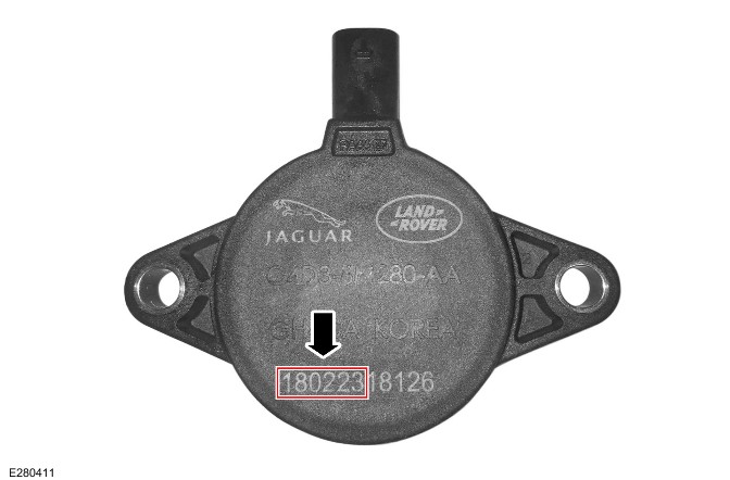
E280411

PINPOINT TEST

PINPOINT TEST A : ACTIVE ENGINE MOUNT TEST
A1: CHECK VACUUM LINES
TEST CONDITIONSDETAILS/RESULTS/ACTIONS
1 Inspect all the vacuum lines for correct connection and for any damage
Are all the vacuum lines correctly connected and free from damage? Yes GO to A2. No Reconnect or replace damaged vacuum lines as required and retest
A2: CHECK ACTIVE ENGINE MOUNT SWITCH POSITION
TEST CONDITIONSDETAILS/RESULTS/ACTIONS
1 Inspect the left and right active engine mount switch positions as shown in the image below
E222279
Is the active engine mount switch clearly visible as shown in the image? Yes The active engine mount is faulty, replace only the faulty active engine mount and retest No GO to A3.
A3: ACTIVE ENGINE MOUNT VACUUM CHECKS
TEST CONDITIONSDETAILS/RESULTS/ACTIONS
1 Disconnect the vacuum lines directly from the active engine mounts
2 Using the Jaguar Land Rover approved vacuum testing equipment, connect to each active engine mount and check it is holding vacuum. The engine mount should switch before 0.4 bar of vacuum is pulled and then be able to hold the vacuum for 1 minute. There will be an audible pop as the engine mount switches
Did the engine mount switch before 0.4 bar is pulled and hold the vacuum for 1 minute? Yes GO to A4. No The active engine mount is faulty, replace only the faulty active engine mount and retest
A4: ACTIVE ENGINE MOUNT SOLENOID CHECKS
TEST CONDITIONSDETAILS/RESULTS/ACTIONS
1 Refer to the electrical circuit diagrams and check the active engine mount solenoid circuit for short circuit to ground, open circuit, high resistance. Repair circuit as required and retest
Did the check and repair of the active engine mount solenoid circuit resolve the issue? Yes No further action is required No Check and install a new active engine mount solenoid as required and retest. If the fault persists, reconfirm the customer symptoms

DTC Index

For a list of Diagnostic Trouble Codes that could be set on this vehicle, please refer to Section 100-00. REFER to: Diagnostic Trouble Code Index - INGENIUM I4 2.0L Diesel, DTC: Powertrain Control Module (PCM) (100-00 General Information, Description and Operation).

Parking Aid (G2748493)

SPECIFICATIONS

Torque Specifications

Component Torque Location
E266210  E266221  E273492  E273493  E273494
DescriptionDescriptionNmlb-ftlb-in
1Driver Assistance Domain Controller (DADC) nuts10788
2Near Field Sensing Module (NFSM) nuts10788
3Accelerator pedal assembly nuts10788
4Front proximity camera screws42.935
5Rear proximity camera screws10788

Advanced Tow Assist (G2748506)

DESCRIPTION AND OPERATION

COMPONENT LOCATION

Component Location - 1 Of 1

NOTE:

  • Right Hand Drive (RHD) vehicle is shown, Left Hand Drive (LHD) vehicle is similar.
  • Vehicle with 5 doors is shown, vehicle with 3 doors is similar.
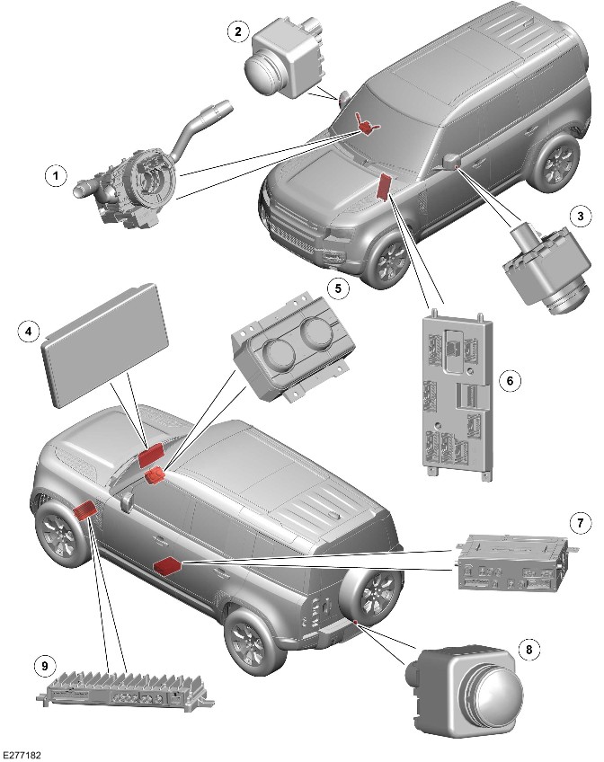
E277182

ItemDescription
1Steering Angle Sensor Module (SASM)
2Right door mirror proximity camera
3Left door mirror proximity camera
4Interactive Display Module 'A' (IDMA)
5Front Controls Interface Module (FCIM)
6Body Control Module (BCM)/Gateway Module A (GWM)
7Front Infotainment Control Module (IGM / ICCM)
8Rear proximity camera
9Near Field Sensing Module (NFSM)

OVERVIEW

Advanced Tow Assist

WARNING:

Make sure the relevant safety warnings and cautions have been read and understood before towing a trailer.

NOTE:

  • The advanced tow assist only operates if the connected trailer has had a profile created, and has been calibrated.
  • The vehicle speed and brakes must be controlled by the driver.

The advanced tow assist feature uses the rear proximity camera view to monitor the position of a connected trailer. Trajectory lines are overlaid onto the images when reversing a trailer. The different camera views can be selected through the IDMA.

When REVERSE is selected, the rear proximity camera automatically displays a wide-angle color image onto the IDMA. The rear proximity camera provides additional information to the driver when hitching a trailer to the vehicle.

The advanced tow assist also operates the steering wheel when the vehicle is reversing, and all conditions are met.

DESCRIPTION

Near Field Sensing Module

NOTE:

RHD vehicle is shown, LHD vehicle is similar.
E277183

The NFSM is located below the instrument panel.

The NFSM has connections for the following:

  • Power
  • Ground
  • FlexRay
  • Parking Aid sensor - Front (quantity 4)
  • Parking Aid sensor - Rear (quantity 4)
  • Park Assist sensor - Front (quantity 2)
  • Park Assist sensor - Rear (quantity 2)
  • Door mirror wade sensor (quantity 2)
  • Proximity camera (quantity 4)
  • IGM / ICCM.

The FlexRay connections provide for the receipt of the following information from BCM/GWM:

  • Integrated Power Brake control module - Vehicle speed signal
  • Transmission Control Module (TCM) - REVERSE engaged signal.

The NFSM gathers the camera images and analyses and alters them by adjusting perspectives and applying corrections. The resulting processed images are then relayed to the screen through the IGM / ICCM on the Automotive Pixel Link 2 (APIX2).

The NFSM also adds guidance and warning overlays to the camera images to create the various driving aid features supported by the proximity camera system. For example, visual direction is made available when reversing the vehicle.

In addition to the data lines, the camera receives a power supply and a ground wire from the NFSM.

Advanced Tow Assist Switch

NOTE:

  • RHD vehicle is shown, LHD vehicle is similar.
  • Vehicle with 5 doors is shown, vehicle with 3 doors is similar.

Advanced Tow Assist Switch
E277184

ItemDescription
1IDMA
2Advanced tow assist switch

The advanced tow assist switch is a soft key on the screen. There is an indicator in the switch to indicate when the system is active.

The soft key is only available when a previously calibrated trailer is connected to the vehicle.

Rear Proximity Camera

NOTE:

  • RHD vehicle is shown, LHD vehicle is similar.
  • Vehicle with 5 doors is shown, vehicle with 3 doors is similar.
E277185

The camera system uses video graphic array resolution cameras. The camera is permanently powered whenever the vehicle is in Power Mode 6 (ignition ON) or Power Mode 7 (engine running).

The rear proximity camera is located in the tailgate next to the license plate.

The camera provides an image covering a zone approximately 130° wide by 112° deep and can capture approximately 30 frames per second.

Camera Mounting

NOTE:

  • RHD vehicle is shown, LHD vehicle is similar.
  • Vehicle with 5 doors is shown, vehicle with 3 doors is similar.
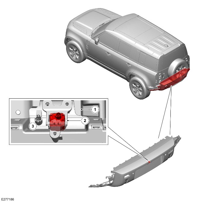
E277186

ItemDescription
1Exterior tailgate
2Rear proximity camera bracket
3Rear proximity camera

The positioning accuracy of the camera is crucial for the successful operation of the rear proximity camera. The camera housings are manufactured using metal to maintain structural stability in high-ambient temperatures. Without this stability, a loss of image focus would be possible. Use caution when installing the camera to make sure that it is inserted correctly into their locations. Secure mounting of the camera provides an initial installation tolerance accurate to 2 mm. The camera calibrates itself automatically. The camera should be calibrated after repairing the body of the vehicle.

OPERATION

Hitch Assist

The rear proximity camera provides additional information to the driver when hitching a trailer to the vehicle. When REVERSE is selected, the rear proximity camera automatically displays a wide-angle color image onto the screen.

Within the settings menu the driver can activate the hitch guidance and the auto towbar zoom features.

  • Hitch guidance - The hitch guidance provides a trajectory line indicating the path of the towbar in relation to the steering angle applied to the vehicle.
  • Auto towbar zoom - Initiates an automatic image zoom when the trailer is within 0.6 m (2 feet) of the towbar. This allows more accurate alignment of vehicle to trailer.

System Calibration

System calibration occurs automatically.

When repairing the body of the vehicle in areas that have an effect on the camera system, please calibrate the camera after the repair. The camera is calibrated using the Jaguar Land Rover (JLR) approved diagnostic equipment.

System Fault

In the event of a camera fault, a Diagnostic Trouble Code(s) (DTC) is set in the NFSM. An icon is presented to the driver on the screen where the camera image would normally be viewed.

Trailer Setup

NOTE:

  • The auto towbar zoom feature is not available in the North American Specification (NAS) market.
  • The tow assist only operates when the connected trailer has had a profile created and has been calibrated.

On first use, the setup screens guide the user through a series of configuration options for the connected trailer.

Trailer Setup - Step 1 of 5
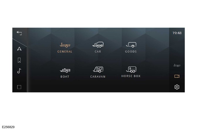
E256829

  • Choose from the list of generic trailer descriptive icons for the trailer attached.

Trailer Setup - Step 2 of 5
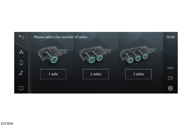
E273504

  • Select the number of axles from the screen.

Trailer Setup - Step 3 of 5
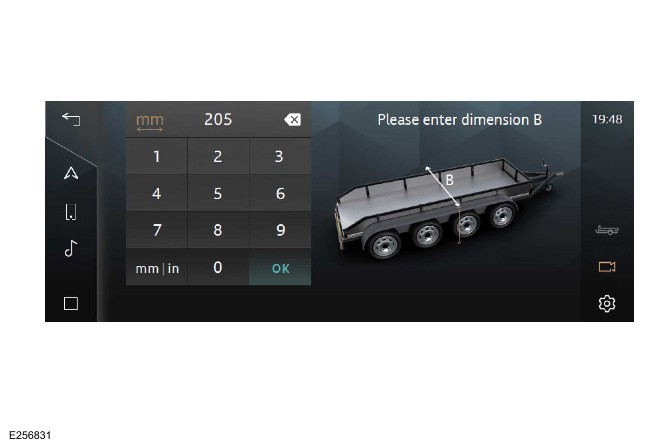
E256831

  • Enter the dimensions of the trailer, then select 'OK'.

Trailer Setup - Step 4 of 5
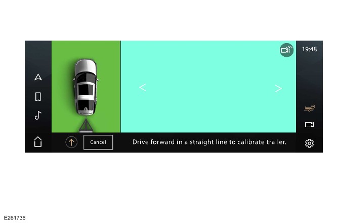
E261736

  • To learn the central position of the trailer, drive the vehicle forward:
    • At less than 24 km/h (15 mph)
    • With the steering wheel in the straight ahead position.

Trailer Setup - Step 5 of 5
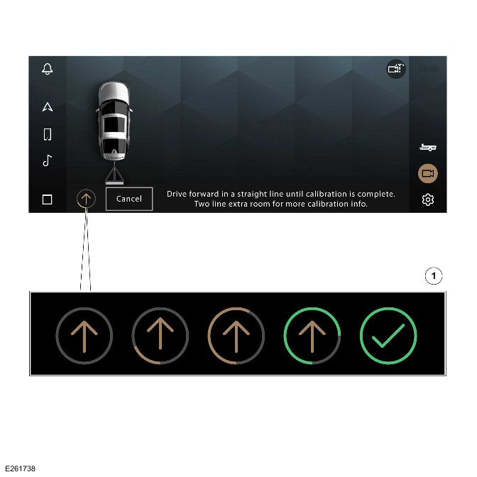
E261738

ItemDescription
1Progress indicator states

As the tracking feature learns the central position, a progress bar appears to show the progress.

The progress indicator in the bottom bar of the setup screen is updated as the trailer is calibrated.

'Trailer Calibration Complete' message is displayed if routine is successful. The tow assist feature is now ready to use.

Advanced tow assist
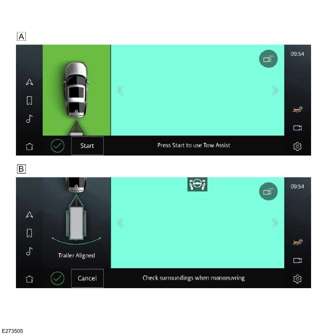
E273505

 
>td >B

ItemDescription
A
The advanced tow assist is activated.

The advanced tow assist is selected on the IDMA by selecting the advanced tow assist soft key. The soft key is available when a previously calibrated trailer is connected and the corresponding 'trailer profile' is selected.

The advanced tow assist feature helps the driver to reverse a previously calibrated trailer. The rear and side cameras provide the views for the advanced tow assist when reversing the vehicle with a trailer. Different camera views can be selected by the IDMA. The trajectory path is overlaid on the image of the IDMA, depicting the predicted path of the trailer.

Colored lines indicate when the trailer is going straight, turning or turning at too great an angle:

  • Green line - Trailer is straight.
  • Magenta line - Trailer is turning.
  • Red line - Trailer is turning at too great an angle.

The angle is adjusted by operating the rotary control on the driver side of the FCIM. The vehicle speed is controlled by the accelerator speed and the brake pedal.

The feature cancels the 'automated steering assist' function when the speed is above 8 km/h (5 mph) .

DIAGNOSTICS

The NFSM records any DTCs and related data. Read the DTCs and related data with the JLR approved diagnostic equipment.

The JLR approved diagnostic equipment can read live data and activate certain components.

Control Diagram

Control Diagram - 1 Of 1
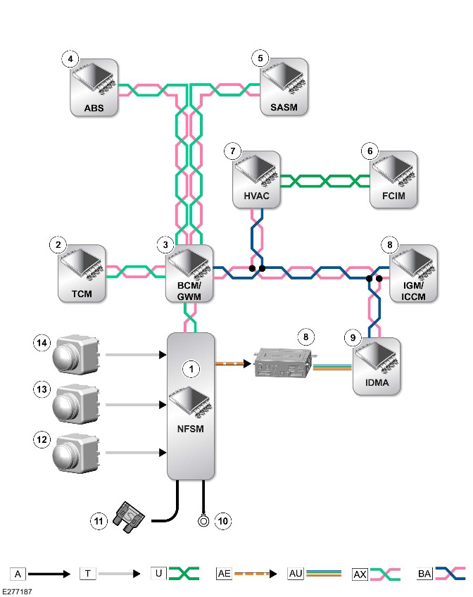
E277187

A = Hardwired: T = CoAxial: U = Private Controller Area Network (CAN) bus: AE = Low-Voltage Differential Signalling (LVDS): AU = APIX2: AX = FlexRay: BA = High Speed (HS) CAN Human Machine Interface (HMI) systems bus.

ItemDescription
1NFSM
2TCM
3BCM/GWM
4Anti-Lock Brake System Control Module (ABS)
5SASM
6FCIM
7HVAC Control Module (HVAC)
8IGM / ICCMT
9IDMA
10Ground
11Power supply
12Right door mirror proximity camera
13Left door mirror proximity camera
14Rear proximity camera


Blind Spot Monitoring System (G2748507)

DESCRIPTION AND OPERATION

COMPONENT LOCATION

Component Location - 1 Of 2

NOTE:

A right hand drive (RHD) vehicle is shown. A left hand drive (LHD) vehicle is similar.
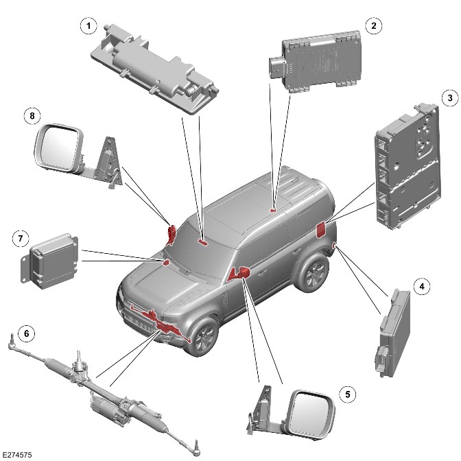
E274575

ItemDescription
1Image Processing Module 'A' (IPMA)
2Side Obstacle Detection Control Module - Right (SODR)
3Audio Amplifier Module (AAM)
4Image Processing Module 'A' (SODL)
5Left door mirror
6Power Steering Control Module (PSCM)
7Driver Assistance Domain Controller (DADC)
8Right door mirror

Component Location - 2 Of 2

NOTE:

A RHD vehicle is shown. ALHD vehicle is similar.
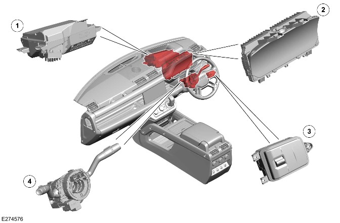
E274576

ItemDescription
1Head Up Display (HUD)
2
3Right steering wheel switch
4>span class="acronym">Steering Angle Sensor Module (SASM) - Integrated into the Steering Wheel Module (SWM)

OVERVIEW

Blind Spot Monitoring System

WARNING:

The Blind Spot Monitoring (BSM) system is a driver aid and not a safety device. The driver must always exercise due care and attention while driving.

The BSM system is a feature to help the driver to safely change lane in moving traffic.

Blind Spot Assist

WARNING:

The blind spot assist system is a driver aid and not a safety device. The driver must always exercise due care and attention while driving.

The blind spot assist is an enhancement to the BSM.

The blind spot assist is designed to help prevent a collision. If the BSM detects a vehicle and the driver attempts to change lane, a counter torque is applied to the steering. The system is designed to guide the host vehicle away from the approaching vehicle.

Approaching Vehicle Sensing

WARNING:

The Approaching Vehicle Sensing (AVS) system is a driver aid and not a safety device. The driver must always exercise due care and attention while driving.

The AVS uses the BSM function to view a larger area to the rear of the vehicle.

The AVS uses the same principle as the BSM. The AVS warns the driver that a vehicle is approaching but is not yet in the blind spot area.

GENERAL SAFETY REGULATIONS 2 (market dependent)

The European Union have introduced General Safety Regulations 2 (GSR2). These are a set of mandatory regulations that require a number of Advanced Driver Assistance Systems (ADAS) be installed on GSR2 market vehicles to protect vehicle occupants, pedestrians, cyclists, and mitigate the human error that cause many accidents.

There must be the capability to record certain data for accident investigation. This data is stored in the DADC.

Required ADAS

  • Traffic Sign Recognition
  • Driver Condition and Attention Monitors
  • Autonomous Emergency Braking (AEB)
  • Emergency Lane Keep Assist
  • Blind Spot Monitor
  • Reverse Traffic Detection
  • Intelligent Speed Control
  • Emergency Stop Signal
  • Event Data Recorder

The GSR2 regulations also set out how these systems must warn the driver when the system is active, off, or in a fault state.

Warnings can be both visual and audible. The audible warning chime is heard through the vehicle infotainment system speakers.

The driver is able to switch a system OFF or ON through the 'Driver Assistance' menu with one press of a button on the steering wheel. The settings will change between 'High' (ON), 'Custom' and 'Low' on the IPC.

Alternatively the setting can be changed using the 'Driver Assistance' menu on the Interactive Display Module 'A' (IDMA) touchscreen.

NOTE:

Forward Collision Warning will never be switched off.

In GSR2 markets, these systems will default to 'High' (ON) after an ignition cycle, even if the driver has previously switched them OFF.

NOTE:

Non-GSR2 market vehicles will also have these ADAS installed, however, the system will not default ON, but instead retain the last driver setting across ignition cycles.

For additional information, refer to https://www.ownerinfo.landrove...

Driver assistance menu Instrument Panel Cluster Control Module B (IPCB)
E390052

ItemDescription
1Driver assistance mode switch
2Driver assistance mode display IPCB

Driver assistance menu IDMA
E390063

ItemDescription
1Low
2Custom
3High
4Speed Limit Warning
5Driver Attention Monitor (Camera - Driver Facing (C-DF))
6Forward Collision Warning

COUNTRIES AND TERRITORIES WITH GSR2 FEATURES

  • Andorra
  • Australia
  • Austria
  • Azores and Madeira
  • Belgium
  • Bulgaria
  • Croatia
  • Cyprus
  • Czech Republic
  • Denmark
  • Estonia
  • Finland
  • France
  • French Guyana
  • Germany
  • Greece
  • Guadeloupe
  • Hungary
  • Iceland
  • Iran
  • Israel
  • Italy
  • Latvia
  • Liechtenstein
  • Lithuania
  • Luxembourg
  • Malta
  • Martinique
  • Mayotte
  • Monaco
  • Netherlands
  • New Zealand
  • Norway
  • Palestine
  • Poland
  • Portugal
  • Republic of Ireland
  • Reunion
  • Romania
  • Slovakia
  • Slovenia
  • Spain
  • St Martin
  • Sweden
  • Switzerland
  • Turkey
  • United Kingdom

DESCRIPTION

Side Obstacle Detection Control Module
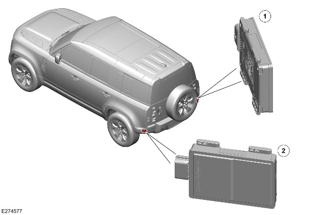
E274577

ItemDescription
1SODR
2SODL

There are 2 side obstacle detection control modules installed in the corners of the rear bumper, 1 on each side.

The SODR has the following connections:

  • Power
  • Ground
  • High Speed (HS) Controller Area Network (CAN) underbody systems bus
  • Private CAN bus.

The SODL does not have a HS CAN underbody systems bus connection. The SODL and SODR are connected through the private CAN bus.

The SODL and SODR provide the monitored data for the following systems:

  • BSM
  • Reverse traffic detection
    • For additional information, refer to: Reverse Traffic Detection (401-02 Driving Aid, Description and Operation).
  • Clear Exit Detection System (CEDS).
    • For additional information, refer to: Warning Devices (413-09 Warning Devices, Description and Operation).

Driver Assistance Domain Controller

NOTE:

A RHD vehicle is shown. A LHD vehicle is similar.
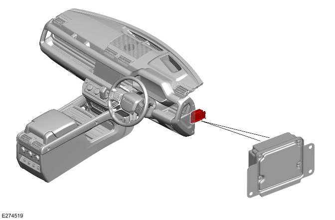
E274519

The DADC is located behind the right of the instrument panel. The DADC is attached to a bracket through 3 nuts.

The DADC helps the driver with monitoring, warning, braking and steering tasks. The DADC hosts the functions of driver assistance system. The DADC collects and processes the information from various sensors. Then the DADC transmits the processed signals to the various control module, warning devices and actuators.

The DADC has connections for the following:

  • Power
  • Ground
  • FlexRay
  • BroadR-Reach®
  • Private CAN bus
  • HS CAN underbody systems bus.

Image Processing Module 'A'

NOTE:

General Safety Regulations 2 (GSR2) markets require that the field of view in front of the IPMA must be equipped with a de-icing element to allow correct operation in cold conditions.
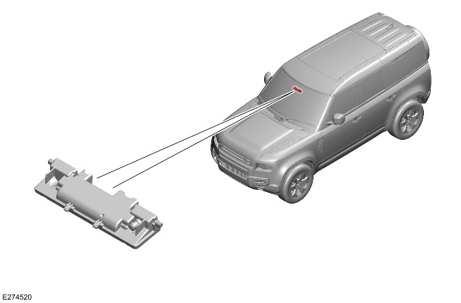
E274520

The IPMA is located centrally at the top of the windshield, behind the rear view mirror cover. The IPMA is attached to a bracket, which is bonded to the windshield.

The IPMA is a module that has an integrated camera with the lens directed through the windshield. The IPMA accurately detects and classifies objects by measuring their movement when they cross the vehicle path. The IPMA is also able to detect road lane markings and traffic sign markings.

The IPMA has connections for the following:

  • Power supply
  • Ground
  • BroadR-Reach®
  • HS CAN underbody systems bus.

Right Steering Wheel Switch

NOTE:

A RHD vehicle is shown. A LHD vehicle is similar.
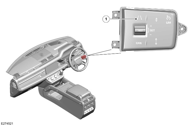
E274521

ItemDescription
1Driver assistance button

The driver assistance button is located on the right steering wheel switch. The driver assistance button turns ALL of the driving aid systems OFF, including the blind spot assist system. A subsequent operation of the button will turn All of the driving aid systems ON.

NOTE:

Depending on the features available on the vehicle, the driver assistance button controls operation of different driver assistance systems.

The driver assistance button also controls operation of the Lane Keep Assist (LKA) system.

For additional information, refer to: Lane Keep Assist (401-02 Driving Aid, Description and Operation).

Instrument Panel Cluster Control Module

NOTE:

A RHD vehicle is shown. A LHD vehicle is similar.
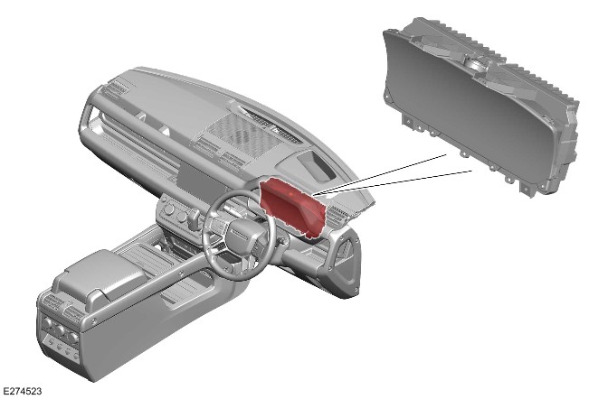
E274523

The IPC is located in driver side of the instrument panel. There is a message center located in the IPC. The message center displays vehicle related information and driver information.

For additional information, refer to: Instrument Panel Cluster (413-01 Instrument Cluster, Description and Operation).

The IPC displays visual warnings to inform the driver of the blind spot assist system status.

Head Up Display

NOTE:

A RHD vehicle is shown. A LHD vehicle is similar.
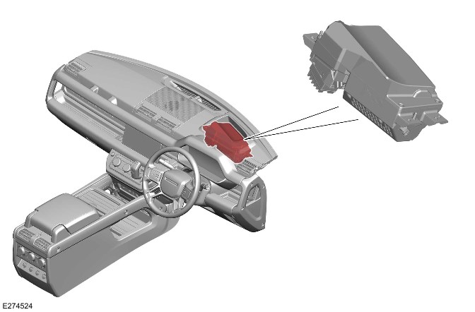
E274524

The HUD is located inside the instrument panel behind the IPC. The HUD is a transparent display that presents data without the driver having to look away from their view of the road ahead. A virtual image is displayed on the front window which appears at a distance of approximately 2 meters.

For additional information, refer to: Instrument Panel Cluster (413-01 Instrument Cluster, Description and Operation).

The HUD also displays visual warnings to inform the driver of the blind spot assist system status.

Power Steering Control Module

NOTE:

A RHD vehicle is shown. A LHD vehicle is similar.
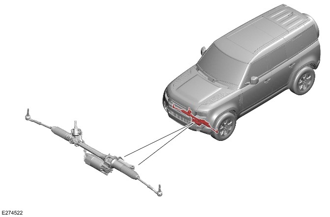
E274522

The electric power steering is provided by a steering gear unit with variable ratio, rack and pinion steering and speed sensitive power assistance. The electric power steering is controlled by the PSCM.

For additional information, refer to: Power Steering (211-02 Power Steering, Description and Operation).

Warning Alert Icon
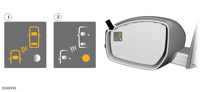
E168593

ItemDescription
1Warning alert icon
2System status warning alert icon

The warning alert icon is located towards the outside extremity of the door mirror glass, within the peripheral view of the driver. The warning alert icon is a Light Emitting Diode (LED). The LED is not in any area of the door mirror where it could obscure of distract from the reflected image.

The warning alert icon tells the driver if there is a vehicle in the blind spot area.

The system status warning alert icon tells the driver if there is a fault in the BSM system.

OPERATION

Blind Spot Monitoring

The BSM system uses 2 radar sensors which are incorporated in each of the SODL and SODR. The SODL and SODR exchange data on the private CAN bus. The SODR communicates the data on the HS CAN underbody system bus to the Body Control Module (BCM)/Gateway Module A (GWM) and the DADC.

Each SODL and SODR do a radar alignment self-check at the start of every journey. The self-check can take up to an hour to complete in some low target environments. The BSM continues to function as normal during the self-check.

The default mode of the BSM system is ON and the system cannot be switched OFF individually. The BSM function can only be switched OFF with all the other driving aids by pressing the driver assistance button. The BSM system activates when the vehicle speed is greater than 10 km/h (6 mph). The BSM remains active until the speed is less than 6 km/h (4 mph).

The BSM uses rear corner radars to detect adjacent lane moving objects and provides a warning on the door mirrors.

The area monitored extends from the door mirrors rearward, to approximately:

  • The 8.5 meters behind the door mirror.
  • Up to 3.3 meters from the side of the vehicle.
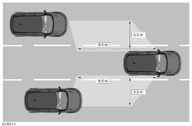
E236513

The driver is alerted with a warning alert icon in the relevant door mirror.

NOTE:

If an passing vehicle is detected on both sides of the vehicle simultaneously, the warning alert icons in both door mirrors illuminate.

The LED alerts are as follows:

  • No LED ON
    • System active, no vehicle detected in blind spot area.
  • Amber warning alert icon permanently ON
    • System operational, vehicle detected in blind spot area.
  • Amber warning alert icon flashing
    • System operational, vehicle detected in blind spot area, turn signal indicator or when vehicle drifts to an adjacent lane.
  • Amber system status warning alert icon permanently ON
    • System is not active or faulty.

NOTE:

The amber warning alert icon flashes in the side of the door mirror when the turn signal indicator is selected.

The BSM system has operating limitations and is automatically switched to OFF under certain operating conditions. During these operating conditions, the amber system status warning alert icon is permanently ON.

The BSM system operating limitations are as follows:

  • The BSM system is inactive until the vehicle speed is greater than 10 km/h (6 mph).
  • The BSM system is inactive if an approved trailer is connected to the vehicle.
  • The BSM system is inactive when REVERSE or PARK is selected.

If any of the radar signals are blocked or distorted, for example, by water, mud, sleet or snow, the BSM system can sense the blockage. In this situation, the amber system status warning alert icon is permanently ON. The BSM system is disabled until the blockage is cleared.

If the communication network fails, it is possible that the system status warning icon cannot be set to ON in the door mirror. If there is a fault in the BSM system, the amber system status warning alert icon is permanently ON until the fault is recovered. When faults are present, the Diagnostic Trouble Codes (DTC) are stored in both side obstacle detection control modules. If you replace a side obstacle detection control module it must be configured with the Jaguar Land Rover (JLR) approved diagnostic equipment.

Blind Spot Assist

The blind spot function can be switched OFF or ON through the driver assistance button on the right steering wheel switch.

The blind spot assist operates when these circumstances occur together:

  • A vehicle is detected in the blind spot area.
  • The driver tries to change lanes.

When the blind spot assist operates, it:

  • Flashes the amber warning alert icon in the related door mirror.
  • Applies a rotational force to the steering to keep the vehicle in the current road lane.
  • An optical warning is displayed in the IPC and the HUD.
  • An audible warning tone is emitted from the speakers.

The blind spot assist system operating limitations are as follows:

  • The blind spot assist system is inactive until the vehicle speed is greater than 10 km/h (6 mph).
  • The blind spot assist system is inactive if an approved trailer is connected to the vehicle.
  • The blind spot assist system is inactive when REVERSE or PARK is selected.

Approaching Vehicle Sensing

The AVS system operates in the same principle as the BSM. The AVS system is automatically switched ON when the BSM system is ON. However the AVS monitors a larger area extending from the back of the BSM zone, to approximately:

  • The 70 meters behind the door mirrors.
  • Up to 3.3 meters from the side of the vehicle.
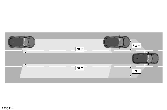
E236514

The AVS system alerts the driver to the presence of a vehicle approaching rapidly beyond the blind spot.

When a vehicle is detected by the AVS system, the following LED lighting sequence occurs:

  • Flashes
    • A vehicle enters the AVS detection zone when a turn signal is operating.
  • Permanently illuminated:
    • A vehicle enters the AVS detection zone when a turn signal is not operating.

NOTE:

The amber warning alert icon flashes in the side of the door mirror when the turn signal indicator is selected.
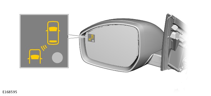
E168595

Diagnostics

The DADC, SODL, SODR and BCM/GWM record any DTC and related data. Read the DTC and related data with the JLR approved diagnostic equipment.

The JLR approved diagnostic equipment can read live data and activate certain components.

CONTROL DIAGRAM

Control Diagram - 1 Of 1
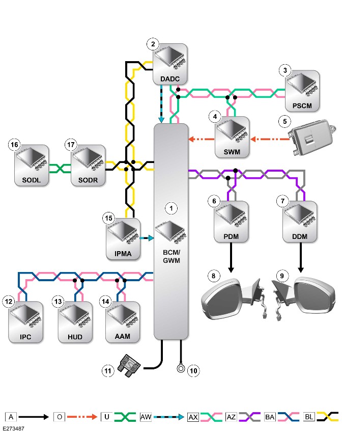
E273487

A = Hardwired: O = Local Interconnect Network (LIN): U = Private CAN bus: AW = BroadR-Reach®: AX = FlexRay: AZ = HS CAN body systems bus: BA = HS CAN Human Machine Interface (HMI) systems bus: BL = HS CAN underbody systems bus.

ItemDescription
1BCM/GWM
2DADC
3PSCM
4SWM
5Right steering wheel switch
6Passenger Front Door Module (PDM)
7Driver Front Door Module (DDM)
8Left door mirror
9Right door mirror
10Ground
11Power supply
12IPC
13HUD
14AAM
15IPMA
16SODL
17SODR

Lane Keep Assist (G2748509)

DESCRIPTION AND OPERATION

COMPONENT LOCATION

Component Location - 1 Of 2

NOTE:

A right hand drive (RHD) vehicle is shown. A left hand drive (LHD) vehicle is similar.
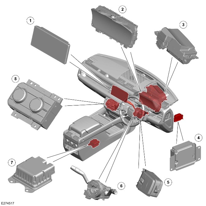
E274517

ItemDescription
1Interactive Display Module 'A' (IDMA)
2
3>span class="acronym">Head Up Display (HUD)
4Driver Assistance Domain Controller (DADC)
5Right steering wheel switch
6Steering Angle Sensor Module (SASM) - Integrated into the Steering Wheel Module (SWM)
7Restraints Control Module (RCM)
8Front Controls Interface Module (FCIM)

Component Location - 2 Of 2

NOTE:

A RHD vehicle is shown. The LHD vehicle is similar.

Vehicle with 5 doors is shown. Vehicle with 3 doors is similar.
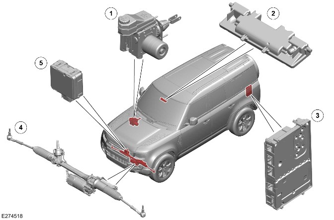
E274518

ItemDescription
1Integrated Power Brake
2Image Processing Module 'A' (IPMA)
3Audio Amplifier Module (AAM)
4Power Steering Control Module (PSCM)
5Cruise Control Module (CCM)

OVERVIEW

Lane Keep Assist

WARNING:

The Lane Keep Assist (LKA) system is designed as a driver aid not a safety device. The driver must always exercise due care and attention while driving.

The LKA monitors the road lane markings in the event of an unintentional road lane departure. If the vehicle is about to cross a lane boundary, a rotational force is applied to the steering wheel to counter the lane boundary crossing. The IPC displays a warning icon when a rotational force is applied to the steering wheel.

The DADC hosts the algorithm which determines how much torque is applied. The LKA system is not designed to offer autonomous steering. The torque is only to assist the driver.

Emergency Lane Keep Assist

WARNING:

The Emergency Lane Keep Assist (ELKA) system is designed as a driver aid not a safety device. The driver must always exercise due care and attention while driving.

The ELKA system attempts to provide corrective steering inputs if it determines the following:

  • The vehicle is getting tool close to horizontal road edges. For example, grass, mud and snow.
  • The vehicle is drifting towards adjacent lane where oncoming vehicles are detected.

GENERAL SAFETY REGULATIONS 2 (market dependent)

The European Union have introduced General Safety Regulations 2 (GSR2). These are a set of mandatory regulations that require a number of Advanced Driver Assistance Systems (ADAS) be installed on GSR2 market vehicles to protect vehicle occupants, pedestrians, cyclists, and mitigate the human error that cause many accidents.

There must be the capability to record certain data for accident investigation. This data is stored in the DADC.

Required ADAS

  • Traffic Sign Recognition
  • Driver Condition and Attention Monitors
  • Autonomous Emergency Braking (AEB)
  • Emergency Lane Keep Assist
  • Blind Spot Monitor
  • Reverse Traffic Detection
  • Intelligent Speed Control
  • Emergency Stop Signal
  • Event Data Recorder

The GSR2 regulations also set out how these systems must warn the driver when the system is active, off, or in a fault state.

Warnings can be both visual and audible. The audible warning chime is heard through the vehicle infotainment system speakers.

The driver is able to switch a system OFF or ON through the 'Driver Assistance' menu with one press of a button on the steering wheel. The settings will change between 'High' (ON), 'Custom' and 'Low' on the IPC.

Alternatively the setting can be changed using the 'Driver Assistance' menu on the IDMA touchscreen.

NOTE:

Forward Collision Warning will never be switched off.

In GSR2 markets, these systems will default to 'High' (ON) after an ignition cycle, even if the driver has previously switched them OFF.

NOTE:

Non-GSR2 market vehicles will also have these ADAS installed, however, the system will not default ON, but instead retain the last driver setting across ignition cycles.

For additional information, refer to https://www.ownerinfo.landrove...

Driver assistance menu Instrument Panel Cluster Control Module B (IPCB)
E390052

ItemDescription
1Driver assistance mode switch
2Driver assistance mode display IPCB

Driver assistance menu IDMA
E390063

ItemDescription
1Low
2Custom
3High
4Speed Limit Warning
5Driver Attention Monitor (Camera - Driver Facing (C-DF))
6Forward Collision Warning

COUNTRIES AND TERRITORIES WITH GSR2 FEATURES

  • Andorra
  • Australia
  • Austria
  • Azores and Madeira
  • Belgium
  • Bulgaria
  • Croatia
  • Cyprus
  • Czech Republic
  • Denmark
  • Estonia
  • Finland
  • France
  • French Guyana
  • Germany
  • Greece
  • Guadeloupe
  • Hungary
  • Iceland
  • Iran
  • Israel
  • Italy
  • Latvia
  • Liechtenstein
  • Lithuania
  • Luxembourg
  • Malta
  • Martinique
  • Mayotte
  • Monaco
  • Netherlands
  • New Zealand
  • Norway
  • Palestine
  • Poland
  • Portugal
  • Republic of Ireland
  • Reunion
  • Romania
  • Slovakia
  • Slovenia
  • Spain
  • St Martin
  • Sweden
  • Switzerland
  • Turkey
  • United Kingdom

DESCRIPTION

Driver Assistance Domain Controller

NOTE:

The RHD vehicle is shown. The LHD vehicle is similar.

E274519

The DADC is located behind the right of the instrument panel. The DADC is attached to a bracket through 3 nuts.

The DADC helps the driver with monitoring, warning, braking and steering tasks. The DADC hosts the functions of driver assistance system. The DADC collects and processes the information from various sensors. Then the DADC transmits the processed signals to the various control module, warning devices and actuators.

The DADC has connections for the following:

  • Power
  • Ground
  • FlexRay
  • BroadR-Reach®
  • Private Controller Area Network (CAN) bus
  • High Speed (HS) CAN underbody systems bus.

Image Processing Module 'A'

NOTE:

General Safety Regulations 2 (GSR2) markets require that the field of view in front of the IPMA must be equipped with a de-icing element to allow correct operation in cold conditions.

E274520

The IPMA is located centrally at the top of the windshield, behind the rear view mirror cover. The IPMA is attached to a bracket, which is bonded to the windshield.

The IPMA is a module that has an integrated camera with the lens directed through the windshield. The IPMA accurately detects and classifies objects by measuring their movement when they cross the vehicle path. The IPMA is also able to detect road lane markings and traffic sign markings.

The IPMA has connections for the following:

  • Power supply
  • Ground
  • BroadR-Reach®
  • HS CAN underbody systems bus.

Right Steering Wheel Switch

NOTE:

A RHD vehicle is shown. A LHD vehicle is similar.

Depending on the features available on the vehicle, the driving aid switch controls operation of different driver assistance systems.

E274521

ItemDescription
1Driving aid switch

The driving aid switch is located on the right steering wheel switch. The driving aid switch operates the LKA system ON or OFF.

The driving aid switch also controls operation of the blind spot assist system.

Power Steering Control Module

NOTE:

A RHD vehicle is shown. A LHD vehicle is similar.

E274522

The electric power steering is provided by a steering gear unit with variable ratio, rack and pinion steering and speed sensitive power assistance. The electric power steering is controlled by the PSCM.

In the LKA system the vehicle applies a steering torque to prevent the vehicle crossing the lane boundary. If the driver overrides the corrective torque, they feel a small resistance.

For additional information, refer to: Power Steering (211-02 Power Steering, Description and Operation).

Instrument Panel Cluster Control Module

NOTE:

A RHD vehicle is shown. A LHD vehicle is similar.

E274523

The IPC is located on the driver side of the instrument panel. There is a message center located in the IPC. The message center displays vehicle related information and driver information.

The IPC displays visual warning to inform the driver of the LKA and ELKA systems status.

For additional information, refer to: Instrument Panel Cluster (413-01 Instrument Cluster, Description and Operation).

Head Up Display

NOTE:

A RHD vehicle is shown. A LHD vehicle is similar.

E274524

The HUD is located inside the instrument panel behind the IPC. The HUD is a transparent display that presents data without the driver requiring to look away from their viewpoint. A virtual image is displayed on the windshield which appears at a distance of approximately 2 meters.

The HUD also displays visual warnings to inform the driver of the LKA and the ELKA systems status.

For additional information, refer to: Instrument Panel Cluster (413-01 Instrument Cluster, Description and Operation).

Interactive Display Module 'A'

NOTE:

A RHD vehicle is shown. A LHD vehicle is similar.
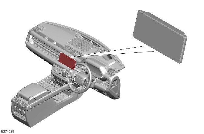
E274525

The IDMA is located in the center of the instrument panel. The ELKA system can be switch ON and OFF in the IDMA.

For additional information, refer to: Audio System (415-01 Information and Entertainment System, Description and Operation).

OPERATION

Lane Keep Assist

NOTE:

If a system fault is detected with the IPC or the HUD, the LKA system continuous to operate as intended.

The LKA system continuously monitors the vehicle position related to the road markings. If the vehicle is about to cross a lane boundary, a rotational force is applied to the steering wheel to counter the lane boundary crossing.

The LKA system applies s steering torque to steer the vehicle back to the center of the road lane when:

  • The vehicle is about to cross a lane boundary.
  • The LKA system does not see an obvious lane change manoeuver of use of the turn signal indicators.

The DADC and electric power steering components determine the trajectory of the vehicle before actuating a corrective steering adjustment. The design is to allow the vehicle to avoid crossing the lane markings.

The IPC message center displays the graphical warning icon to inform the driver when the LKA system is intervening. The color of the graphical warning icon changes from green to red to indicate the side of the intervention. The HUD also displays the warning.

Graphical Warning Icon

NOTE:

The graphical warning icon is always updated with lane tracking/intervention information. The message center is updated with lane tracking/intervention information only if the advanced driver assistance systems view war previously switched ON.
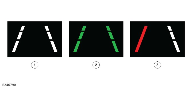
E246790

ItemDescription
1LKA system in passive mode - Lanes are not being tracked
2LKA system in active mode - Lanes are being tracked
3A solid red line to indicate that the vehicle has crossed the boundary

The LKA system can be switched ON and OFF through the driving aid switch. The switch illuminated green when the LKA system is switched ON. The LKA system selection is retained across all ignition cycles.

The LKA system never applies a torque of a magnitude that the vehicle cannot be easily controlled by the driver. The driver can temporarily override the LKA system by applying an overwhelming steering input. This input allows the vehicle to change lanes unhindered.

The following limitations can cause the LKA system to become inactive:

  • REVERSE or PARK is selected.
  • The brake pedal is pressed.
  • A turn signal indicator is being used.
  • The road markings are not available and not detected or in poor condition.
  • The vehicle speed is below 64 km/h (40 mph) or above 180 km/h (112 mph).
  • Driving in 2 lines (The distance of the 2 lines is narrower than approximately 3 meters or wider than approximately 4 meters).
  • Turning in tight road bends.
  • The Dynamic Stability Control (DSC) is active.
  • An Anti-lock brake event has occurred.
  • A fault occurs in the system.
  • The driver applies a counter steering input that is greater than the steering input from the LKA system.

The performance of the LKA system may be affected in the following conditions:

  • During adverse driving conditions if the camera has impaired vision. For example:
    • Heavy fog
    • Rain
    • Snow
    • Direct sunlight
    • Soiled front window.
  • Worn, damaged or temporary lane markings. For example, road works.
  • Tight deviations of the roads and their gradients.
  • Driving very close with the front vehicle.

In the event of an LKA system fault, the feature is suppressed until the fault is rectified. The driver is informed by a message and a warning indicator comes on in the IPC.

Emergency Lane Keep Assist

NOTE:

Make sure that the ELKA system is disabled when connecting a trailer.

Make sure that the ELKA system is switched OFF before driving off road.

The ELKA system is an extension of the LKA system.

The ELKA system automatically switches ON every time when the vehicle ignition is switched ON. The ELKA system can be switched ON or OFF through the IDMA. To switch the system ON or OFF, complete the following steps:

  • Touch the Setting soft key from any screen
  • Select Vehicle
  • Select Driver Assistance
  • Touch the Emergency lane keeping soft key to switch ON or OFF.

The IPC and the HUD display the graphical warning icon to inform the driver when the ELKA system is intervening. The vehicle speakers also provide audio warnings.

NOTE:

If a system fault is detected with the IPC or the HUD, the ELKA system continues to operate as intended.

The ELKA system operates irrespective of the use of the turn signal indicators.

The following limitations can cause the ELKA system to become inactive:

  • REVERSE or PARK is selected.
  • The brake pedal is pressed.
  • The road markings are not available and not detected or in poor condition.
  • The vehicle speed is below 64 km/h (40 mph) or above 180 km/h (112 mph).
  • Driving in 2 lines (The distance of the 2 lines is narrower than approximately 3 meters or wider than approximately 4 meters).
  • Turning in tight road bends.
  • A fault occurs in the system.
  • The driver applies a counter steering input that is greater than the steering input from the LKA system.

The performance of the ELKA system can be affected in the following conditions:

  • The windshield area in front of the rear view mirror becomes blocked by tickers, mud, snow or debris.
  • Adverse weather conditions exist. For example, heavy fog , rain, snow, very bright sunlight or low on the horizon.
  • The DSC is active.
  • An Anti-lock brake event has occurred.

In the event of an ELKA system fault, the feature is suppressed until the fault is rectified. The driver is informed by a message and a warning indicator in the IPC.

Diagnostics

The DADC and the IPMA record any Diagnostic Trouble Codes (DTC) and related data. Read the DTC and related data with the Jaguar Land Rover (JLR) approved diagnostic equipment.

The JLR approved diagnostic equipment can read live data and active certain components.

CONTROL DIAGRAM

Control Diagram - 1 Of 1
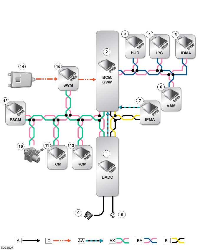
E274526

A = Hardwired: O = Local Interconnect Network (LIN): AW = BroadR-Reach®: AX = Flexray: BA = HS CAN Human Machine Interface (HMI) systems bus: BL = HS CAN underbody systems bus.

ItemDescription
1DADC
2Body Control Module (BCM)/Gateway Module A (GWM)
3HUD
4IPC
5IDMA
6AAM
7IPMA
8Ground
9Power supply
10Integrated Power Brake
11Transmission Control Module (TCM)
12RCM
13PSCM
14Right steering wheel switch
15SWM


Reverse Traffic Detection (G2748510)

DESCRIPTION AND OPERATION

COMPONENT LOCATION

Component Location - 1 Of 2 - Reverse Traffic Detection System

NOTE:

A right hand drive (RHD) vehicle is shown. A left hand drive (LHD) vehicle is similar.

Vehicle with 5 doors is shown. Vehicle with 3 doors is similar.
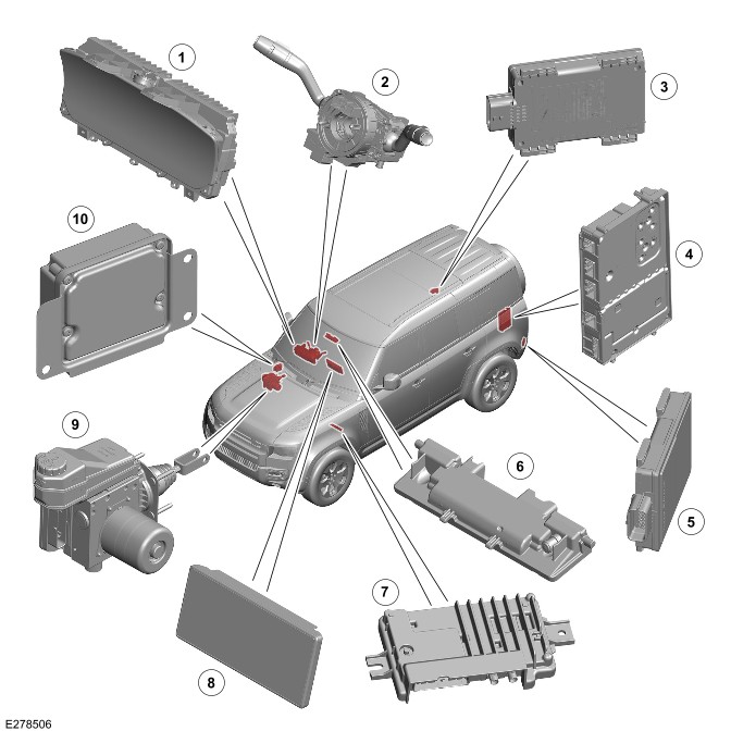
E278506

ItemDescription
1
2>span class="acronym">Steering Angle Sensor Module (SASM) - Integrated into the Steering Wheel Module (SWM)
3Side Obstacle Detection Control Module - Right (SODR)
4Audio Amplifier Module (AAM)
5Image Processing Module 'A' (SODL)
6Image Processing Module 'A' (IPMA)
7Near Field Sensing Module (NFSM)
8Interactive Display Module 'A' (IDMA)
9Integrated Power Brake
10Driver Assistance Domain Controller (DADC)

Component Location - 2 of 2 - Rear Protection Monitor System

NOTE:

A RHD vehicle is shown. A LHD vehicle is similar.

Vehicle with 5 doors is shown. Vehicle with 3 doors is similar.
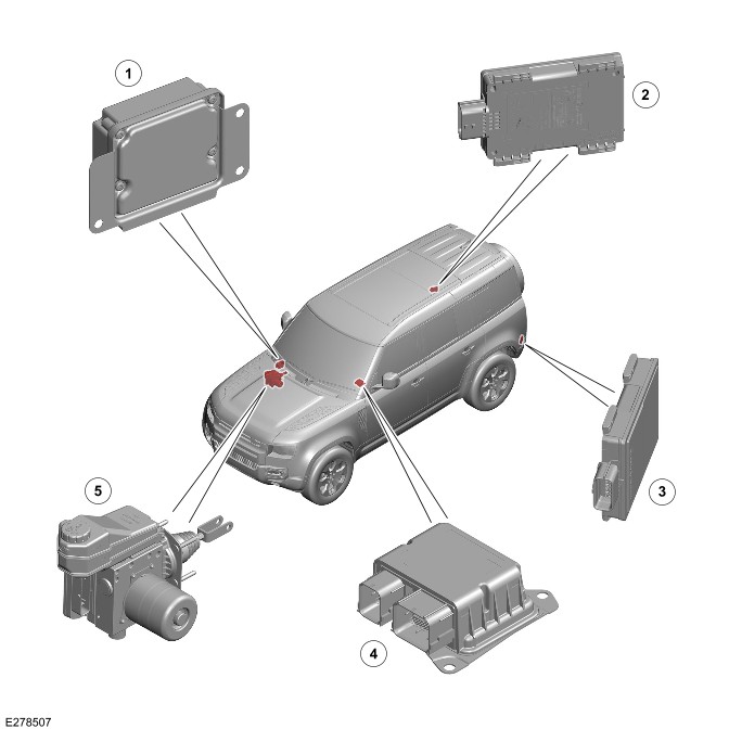
E278507

ItemDescription
1DADC
2SODR
3SODL
4Restraints Control Module (RCM)
5Integrated Power Brake

OVERVIEW

Reverse Traffic Detection

WARNING:

The reverse traffic detection system is designed as a driver aid not a safety device. The driver must always exercise due care and attention while driving.

The reverse traffic detection system uses the side obstacle detection control modules to identify potential collision risks rearward of the host vehicle. The system warns the driver when a threat is identified, and applies emergency braking if a collision is determined to be imminent.

The reverse traffic detection system is split into 2 main features:

  • Rear traffic warning
    • The rear traffic warning feature detects cross traffic moving target objects. The visual and audible warnings are provided when a threat is identified.
  • Rear traffic braking.
    • In the event of an imminent collision, the rear traffic braking feature applies the brakes in order to prevent an accident.. The emergency braking warning is displayed on the IPC.

Rear Protection Monitor

WARNING:

The rear protection monitor system is designed as a driver aid not a safety device. The driver must always exercise due care and attention while driving.

The rear protection monitor system helps identify any potential collision risks approaching the rear of the host vehicle.

The system provides the rear collision alert to the approaching driver by flashing the hazard warning lamps rapidly.

GENERAL SAFETY REGULATIONS 2 (market dependent)

The European Union have introduced General Safety Regulations 2 (GSR2). These are a set of mandatory regulations that require a number of Advanced Driver Assistance Systems (ADAS) be installed on GSR2 market vehicles to protect vehicle occupants, pedestrians, cyclists, and mitigate the human error that cause many accidents.

There must be the capability to record certain data for accident investigation. This data is stored in the DADC.

Required ADAS

  • Traffic Sign Recognition
  • Driver Condition and Attention Monitors
  • Autonomous Emergency Braking (AEB)
  • Emergency Lane Keep Assist
  • Blind Spot Monitor
  • Reverse Traffic Detection
  • Intelligent Speed Control
  • Emergency Stop Signal
  • Event Data Recorder

The GSR2 regulations also set out how these systems must warn the driver when the system is active, off, or in a fault state.

Warnings can be both visual and audible. The audible warning chime is heard through the vehicle infotainment system speakers.

The driver is able to switch a system OFF or ON through the 'Driver Assistance' menu with one press of a button on the steering wheel. The settings will change between 'High' (ON), 'Custom' and 'Low' on the IPC.

Alternatively the setting can be changed using the 'Driver Assistance' menu on the IDMA touchscreen.

NOTE:

Forward Collision Warning will never be switched off.

In GSR2 markets, these systems will default to 'High' (ON) after an ignition cycle, even if the driver has previously switched them OFF.

NOTE:

Non-GSR2 market vehicles will also have these ADAS installed, however, the system will not default ON, but instead retain the last driver setting across ignition cycles.

For additional information, refer to https://www.ownerinfo.landrove...

Driver assistance menu Instrument Panel Cluster Control Module B (IPCB)
E390052

ItemDescription
1Driver assistance mode switch
2Driver assistance mode display IPCB

Driver assistance menu IDMA
E390063

ItemDescription
1Low
2Custom
3High
4Speed Limit Warning
5Driver Attention Monitor (Camera - Driver Facing (C-DF))
6Forward Collision Warning

COUNTRIES AND TERRITORIES WITH GSR2 FEATURES

  • Andorra
  • Australia
  • Austria
  • Azores and Madeira
  • Belgium
  • Bulgaria
  • Croatia
  • Cyprus
  • Czech Republic
  • Denmark
  • Estonia
  • Finland
  • France
  • French Guyana
  • Germany
  • Greece
  • Guadeloupe
  • Hungary
  • Iceland
  • Iran
  • Israel
  • Italy
  • Latvia
  • Liechtenstein
  • Lithuania
  • Luxembourg
  • Malta
  • Martinique
  • Mayotte
  • Monaco
  • Netherlands
  • New Zealand
  • Norway
  • Palestine
  • Poland
  • Portugal
  • Republic of Ireland
  • Reunion
  • Romania
  • Slovakia
  • Slovenia
  • Spain
  • St Martin
  • Sweden
  • Switzerland
  • Turkey
  • United Kingdom

DESCRIPTION

Side Obstacle Detection Control Module

NOTE:

Vehicle with 5 doors is shown. Vehicle with 3 doors is similar.

E274577

ItemDescription
1SODR
2SODL

There are 2 side obstacle detection control modules installed in the corners of the rear bumper, 1 on each side. A radar sensor is incorporated in each of the SODL/SODR.

The SODR has the following connections:

  • Power
  • Ground
  • Private Controller Area Network (CAN) bus
  • High Speed (HS) CAN underbody systems bus.

The SODL does not have a HS CAN underbody systems bus connection. The SODR and SODL are connected through the private CAN bus.

The SODR and SODL provide the monitored data for the following systems:

  • Blind Spot Monitoring (BSM)
    • For additional information, refer to: Blind Spot Monitoring System (401-02 Driving Aid, Description and Operation).
  • Reverse traffic detection
  • Rear protection monitor
  • Clear Exit Detection System (CEDS).
    • For additional information, refer to: Warning Devices (413-09 Warning Devices, Description and Operation).

Driver Assistance Domain Controller

NOTE:

A RHD vehicle is shown. A LHD vehicle is similar.

E274519

The DADC is located behind the right of the instrument panel. The DADC is attached to a bracket with 3 nuts.

The DADC helps the driver with monitoring, warning, braking and steering tasks. The DADC hosts the functions of driver assistance system. The DADC collects and processes the information from various sensors. Then the DADC transmits the processed signals to the various control modules, warning devices and actuators.

The DADC has connections for the following:

  • Power
  • Ground
  • FlexRay
  • BroadR-Reach®
  • Private CAN bus
  • HS CAN underbody systems bus.

Near Field Sensing Module

NOTE:

A RHD vehicle is shown. A LHD vehicle is similar.
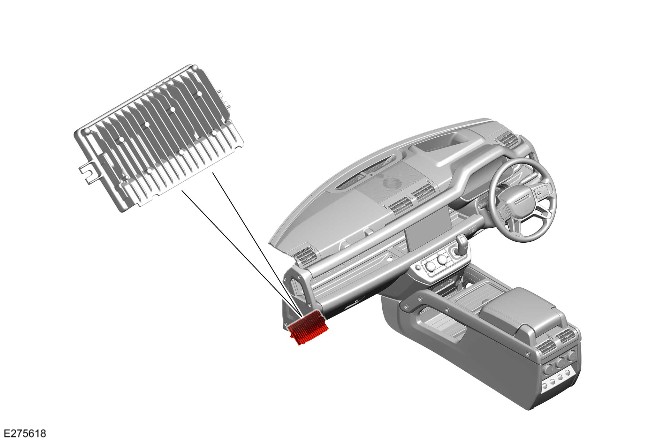
E275618

The NFSM is located below the instrument panel.

The NFSM is the main controller of the Parking Aid system. The NFSM provides the rear view camera signal to the reverse traffic detection system.

The NFSM also adds guidance and warning overlays to the camera image. Overlays are added to the side camera image as well, depending on the camera system installed to the vehicle and view selected by the driver. For example, visual direction is made available when reversing the vehicle.

In addition to the data lines, the camera has a power supply and a ground connection from the NFSM. Use caution when you remove, install, disconnect and reconnect the camera harnesses.

Instrument Panel Cluster Control Module

NOTE:

A RHD vehicle is shown. A LHD vehicle is similar.

E274523

The IPC is located in driver side of the instrument panel. There is a message center located in the IPC. The message center displays vehicle related information and driver information.

For additional information, refer to: Instrument Panel Cluster (413-01 Instrument Cluster, Description and Operation).

The IPC displays visual warnings to inform the driver of an automatic braking event.

Interactive Display Module 'A'

NOTE:

A RHD vehicle is shown, A LHD vehicle is similar.

E274525

The IDMA is located in the center of the instrument panel.

For additional information, refer to: Audio System (415-01 Information and Entertainment System, Description and Operation).

The reverse traffic detection system can be switched ON and OFF through the IDMA screen. The IDMA provides a rear view camera and displays an alert if a threat is detected.

OPERATION

Reverse Traffic Detection

The reverse traffic detection system is used to prevent or mitigate collisions between the host vehicle and other road users during a reversing manouevre. The system only operates when the vehicle is in REVERSE gear and the vehicle speed is less than 16 km/h (10 mph). The system can detect cross traffic speeds of up to 70 km/h (43 mph). Within the detection zone, the system can detect the following objects:

  • Pedestrians
  • Cyclists
  • Passenger vehicles
  • Motorbikes or quads
  • Vans
  • Trucks
  • Buses.

The reverse traffic detection system is hosted in the side obstacle detection control modules with the decisions being made in the DADC. The system performance may be reduced when the following conditions occur:

  • Heavy deposits of mud on the rear bumper.
  • Poor weather. For example: snow or heavy rainfall.
  • Radar misalignment.
  • Bumper damage.
  • Incompatible bumper paint.
  • Unapproved bumper additions.

The reverse traffic detection system is active irrespective of the Park Assist feature activation status.

Rear traffic warning
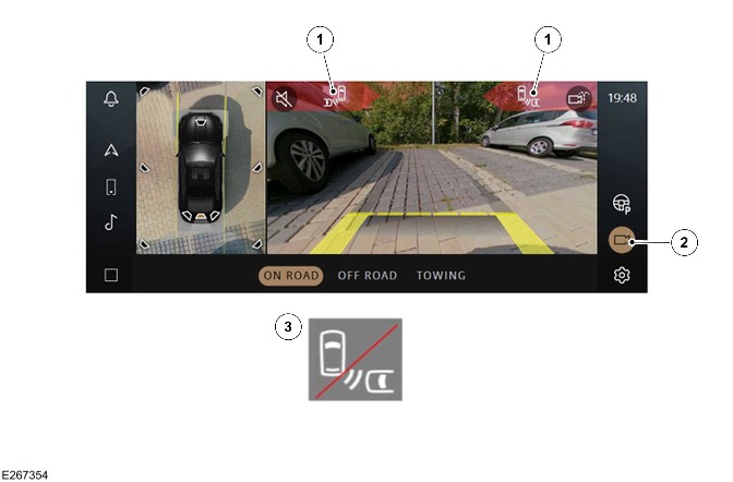
E267354

ItemDescription
1Collision impact alert icon (quantity 2)
2Camera icon
3Icon - Rear traffic monitor unavailable

The rear traffic warning feature is active when the vehicle is in REVERSE gear. When the feature is activated, the IDMA displays the 'collision impact alert' icon on the relevant side of the screen. The 'collision impact alert' icon informs the driver that the vehicle is about to reverse into the path of a moving object. The objects are detected by the side object detection modules. The reverse traffic detection system also uses the steering angle sensor signal and the wheel speed sensor signals during operation. The collision impact visual alert appears on the IDMA.

The rear traffic warning feature can be switched ON or OFF through the IDMA. To switch the feature ON or OFF, complete the following steps:

  • Touch the 'Settings' soft key from any screen.
  • Select 'Vehicle'.
  • Select 'Driver Assistance'.
  • Select 'Collision avoidance'.
  • Touch the 'Rear Traffic Warning' soft key to switch ON or OFF.

NOTES:

  • If the rear traffic warning feature is switched OFF, the 'collision impact alert' icon does not display and no audio alerts sound.
  • The rear traffic warning feature selection is retained across all ignition cycles.

If there is a fault in the rear traffic warning feature, the 'rear traffic monitor unavailable' icon is displayed on the IDMA.

Rear traffic braking

The rear traffic braking feature is activated when the vehicle is moving in REVERSE gear at speeds up to 10 km/h (5 mph). When the feature is activated and a collision is determined to be imminent, an emergency brake request is sent to the Integrated Power Brake control module. The Integrated Power Brake control module applies the brake to prevent or mitigate the collision and remains applied for 2 seconds. During the brake event, the message 'Emergency Braking was activated' is displayed on the IPC. The rear traffic braking feature is suspended when the driver applies acceleration or braking.

The rear traffic braking feature can be switched ON or OFF through the IDMA. To switch the feature ON or OFF, complete the following steps:

  • Touch the 'Settings' soft key from any screen.
  • Select 'Vehicle'.
  • Select 'Driver Assistance'.
  • Select 'Collision avoidance'.
  • Touch the 'Rear Traffic Braking' soft key to switch ON or OFF.

NOTES:

  • If the rear traffic braking feature is switched OFF, the system does not apply the brakes if an imminent collision is detected.
  • The rear traffic braking feature selection is retained across all ignition cycles.

If there is a fault in the rear traffic braking feature, the icon (rear traffic monitor unavailable) is displayed on the IDMA. If there is a fault in the Integrated Power Brake control module, the warning message 'Emergency Braking not available' is displayed on the IPC.

Rear Protection Monitor

The rear protection monitor system is designed to provide the rear-end collision alert signal by operating the hazard warning lamps. The system warns the driver of the vehicle approaching behind, of any potential collision by flashing the hazard warning lamps rapidly. The system uses the side obstacle detection control modules to detect a potential collision threat from a vehicle approaching the rear of the host vehicle.

For additional information, refer to: Exterior Lighting (417-01 Exterior Lighting, Description and Operation).

The rear protection monitor system default mode is ON and the system cannot be switched OFF. The rear protection monitor system does not operate when:

  • The transmission is in REVERSE.
  • The relative speed between the host vehicle and threat vehicle is below 10 km/h (6 mph).
  • The side obstacle detection control modules in the rear bumper become blocked.
  • A vehicle crash is detected.
  • An approved trailer is connected to the vehicle.

The rear protection monitor system:

  • May register false targets if traveling along a narrow lane or in stop and go traffic.
  • Does not work accurately if the radars are misaligned due to bumper modifications or impact damage.

Diagnostics

The DADC and the side obstacle detection control modules record any Diagnostic Trouble Codes (DTC) and related data. Read the DTC and related data with the Jaguar Land Rover (JLR) approved diagnostic equipment.

The JLR approved diagnostic equipment can read live data and activate certain components.

CONTROL DIAGRAM

Control Diagram - 1 of 2 - Reverse Traffic Detection System
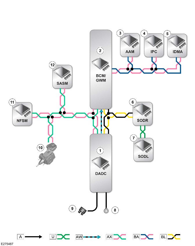
E275487

A = Hardwired: U = Private CAN bus: AW = BroadR-Reach®: AX = FlexRay: BA = HS CAN Human Machine Interface (HMI) systems bus: BL = HS CAN underbody systems bus.

ItemDescription
1DADC
2Body Control Module (BCM)/Gateway Module A (GWM)
3AAM
4IPC
5IDMA
6SODR
7SODL
8Ground
9Power supply
10Integrated Power Brake
11NFSM
12SASM - Integrated into the SWM.

Control Diagram - 2 of 2 - Rear Protection Monitor System
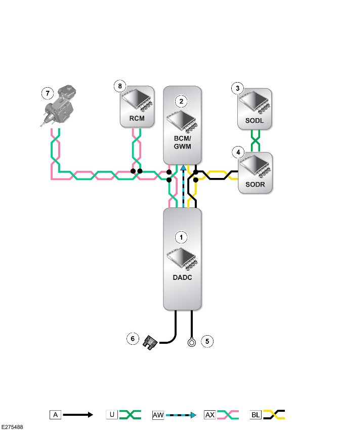
E275488

A = Hardwired: U = Private CAN bus: AW = BroadR-Reach®: AX = FlexRay: BL = HS CAN underbody systems bus.

ItemDescription
1DADC
2BCM/GWM
3SODL
4SODR
5Ground
6Power supply
7Integrated Power Brake
8RCM

Traffic Sign Recognition (G2748511)

DESCRIPTION AND OPERATION

COMPONENT LOCATION

Component Location - 1 Of 2

NOTE:

A right hand drive (RHD) vehicle is shown. A left hand drive (LHD) vehicle is similar.
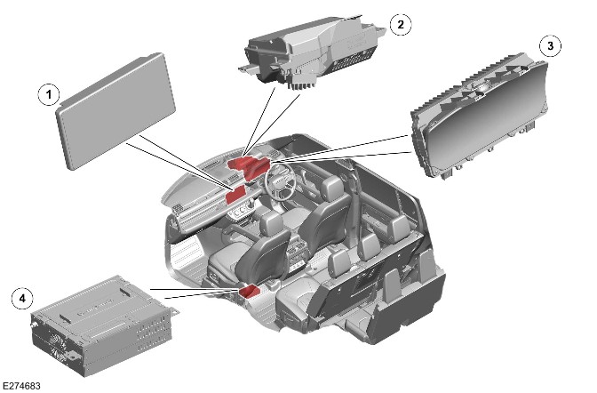
E274683

ItemDescription
1Interactive Display Module 'A' (IDMA)
2Head Up Display (HUD)
3
4>span class="acronym">Front Infotainment Control Module (IGM / ICCM)

Component Location - 2 Of 2

E274684

ItemDescription
1Image Processing Module 'A' (IPMA)
2Driver Assistance Domain Controller (DADC)

OVERVIEW

WARNING:

The Traffic Sign Recognition (TSR) system is a driver aid and not a safety device. The driver must always exercise due care and attention while driving.

The TSR system uses the IPMA to identify traffic signs on either side of the road and on bridges. The TSR system gives the driver information about the latest:

  • Detected speed limit
  • Cancellation signs
  • Passing regulations.

This information displays in the IPC and the HUD.

GENERAL SAFETY REGULATIONS 2 (market dependent)

The European Union have introduced General Safety Regulations 2 (GSR2). These are a set of mandatory regulations that require a number of Advanced Driver Assistance Systems (ADAS) be installed on GSR2 market vehicles to protect vehicle occupants, pedestrians, cyclists, and mitigate the human error that cause many accidents.

There must be the capability to record certain data for accident investigation. This data is stored in the DADC.

Required ADAS

  • Traffic Sign Recognition
  • Driver Condition and Attention Monitors
  • Autonomous Emergency Braking (AEB)
  • Emergency Lane Keep Assist
  • Blind Spot Monitor
  • Reverse Traffic Detection
  • Intelligent Speed Control
  • Emergency Stop Signal
  • Event Data Recorder

The GSR2 regulations also set out how these systems must warn the driver when the system is active, off, or in a fault state.

Warnings can be both visual and audible. The audible warning chime is heard through the vehicle infotainment system speakers.

The driver is able to switch a system OFF or ON through the 'Driver Assistance' menu with one press of a button on the steering wheel. The settings will change between 'High' (ON), 'Custom' and 'Low' on the IPC.

Alternatively the setting can be changed using the 'Driver Assistance' menu on the IDMA touchscreen.

NOTE:

Forward Collision Warning will never be switched off.

In GSR2 markets, these systems will default to 'High' (ON) after an ignition cycle, even if the driver has previously switched them OFF.

NOTE:

Non-GSR2 market vehicles will also have these ADAS installed, however, the system will not default ON, but instead retain the last driver setting across ignition cycles.

For additional information, refer to https://www.ownerinfo.landrove...

Driver assistance menu Instrument Panel Cluster Control Module B (IPCB)
E390052

ItemDescription
1Driver assistance mode switch
2Driver assistance mode display IPCB

Driver assistance menu IDMA
E390063

ItemDescription
1Low
2Custom
3High
4Speed Limit Warning
5Driver Attention Monitor (Camera - Driver Facing (C-DF))
6Forward Collision Warning

COUNTRIES AND TERRITORIES WITH GSR2 FEATURES

  • Andorra
  • Australia
  • Austria
  • Azores and Madeira
  • Belgium
  • Bulgaria
  • Croatia
  • Cyprus
  • Czech Republic
  • Denmark
  • Estonia
  • Finland
  • France
  • French Guyana
  • Germany
  • Greece
  • Guadeloupe
  • Hungary
  • Iceland
  • Iran
  • Israel
  • Italy
  • Latvia
  • Liechtenstein
  • Lithuania
  • Luxembourg
  • Malta
  • Martinique
  • Mayotte
  • Monaco
  • Netherlands
  • New Zealand
  • Norway
  • Palestine
  • Poland
  • Portugal
  • Republic of Ireland
  • Reunion
  • Romania
  • Slovakia
  • Slovenia
  • Spain
  • St Martin
  • Sweden
  • Switzerland
  • Turkey
  • United Kingdom

DESCRIPTION

DRIVER ASSISTANCE DOMAIN CONTROLLER

NOTE:

A RHD vehicle is shown. A LHD vehicle is similar.

E274519

The DADC is located behind the right of the instrument panel. The DADC is attached to a bracket through 3 nuts.

The DADC helps the driver with monitoring, warning, braking and steering tasks. The DADC hosts the functions of driver assistance system. The DADC collects and processes the information from various sensors. Then the DADC transmits the processed signals to the various control modules, warning devices and actuators.

The DADC has connections for the following:

  • Power
  • Ground
  • FlexRay
  • BroadR-Reach®
  • Private Controller Area Network (CAN) bus
  • High Speed (HS) CAN underbody systems bus.

IMAGE PROCESSING MODULE 'A'

NOTE:

General Safety Regulations 2 (GSR2) markets require that the field of view in front of the IPMA must be equipped with a de-icing element to allow correct operation in cold conditions.

E274520

The IPMA is located centrally at the top of the windshield, behind the rear view mirror cover. The IPMA is attached to a bracket, which is bonded to the windshield.

The IPMA is a module that has an integrated camera with the lens directed through the windshield. The IPMA accurately detects and classifies objects by measuring their movement when they cross the vehicle path. The IPMA is also able to detect road lane markings and traffic sign markings.

The IPMA has connections for the following:

  • Power
  • Ground
  • BroadR-Reach®
  • HS CAN underbody systems bus.

INSTRUMENT PANEL CLUSTER CONTROL MODULE

NOTE:

A RHD vehicle is shown. A LHD vehicle is similar.

E274523

The IPC is located in the driver side of the instrument panel. There is a message center located in the IPC. The message center displays vehicle related information and driver information.

For additional information, refer to: Instrument Panel Cluster (413-01 Instrument Cluster, Description and Operation).

The IPC displays symbols of recognized traffic signs and speed limit information to the driver.

HEAD UP DISPLAY

NOTE:

A RHD vehicle is shown. A LHD vehicle is similar.

E274524

The HUD is located inside the instrument panel behind the IPC. The HUD is a transparent display that presents data without the driver having to look away from their view of the road ahead. A virtual image is displayed on the windshield which appears at a distance of approximately 2 meters.

For additional information, refer to: Instrument Panel Cluster (413-01 Instrument Cluster, Description and Operation).

The HUD also displays symbols of recognized traffic signs and speed limit information to the driver.

INTERACTIVE DISPLAY MODULE 'A'

NOTE:

A RHD vehicle is shown. A LHD vehicle is similar.

E274525

The IDMA is located in the center of the instrument panel. The TSR system allows the driver to set a speed limit alert when the vehicle exceeds the speed limit. The alert can be accessed on the IDMA.

For additional information, refer to: Audio System (415-01 Information and Entertainment System, Description and Operation).

OPERATION

NOTE:

The TSR system is only available on vehicles with navigation installed.

The TSR system is not available in markets where there is a poor or non-existent map and navigation database.

The TSR system is not available in unsupported countries.
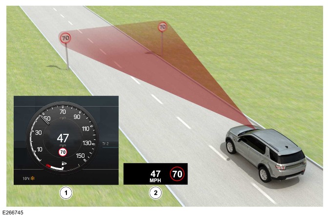
E266745

ItemDescription
1IPC
2HUD

The TSR system captures image data of the road scene. The IPMA within the camera detects speed limit signs, no passing signs and variable overhead speed signs. The IPMA sends the detected information to the DADC through the BroadR-Reach®.

The DADC also obtains information about the current road from the navigation system through the BroadRReach ®. This data includes the current road speed limit, road type and country.

The DADC combines the available speed limit information from the navigation system and the IPMA to provide an accurate and consistently available speed limit value. The speed limit value is sent to the IPC and the HUD which display the information to the driver. The speed limit value is sent through the HS CAN Human Machine Interface (HMI) systems bus.

The default mode of the TSR system is ON and the system cannot be disabled. The driver can use the TSR system to provide an alert when the vehicle exceeds the speed limit. The TSR system flashes the speed limit sign on the IPC when the vehicle exceeds the displayed speed limit by a set amount. To access the speed limit alert menu, complete the following steps on the IDMA:

  • Touch the Settings soft key on the IDMA.
  • Select Vehicle.
  • Select Driver Assistance.
  • Select Cruise and speed assistance.
  • Touch the Speed limit warning soft key to select the required setting.

The settings of the speed limit alert can be adjusted by the driver. The settings are:

  • Vehicle speed equals the detected speed limit.
  • Vehicle speed is greater than 5 km/h (3 mph) over the detected speed limit.
  • Vehicle speed is greater than 10 km/h (5 mph) over the detected speed limit.

In the event that the TSR system becomes unavailable, the speed limit alert feature also becomes unavailable.

The TSR system uses the IPMA but cannot operate to full functionality when the following occurs:

  • The navigation system is not available.
  • The off road navigation is selected.

The performance of the TSR system may also be affected in the following conditions:

  • During adverse driving conditions and the camera has impaired vision (reduced visibility less than 1 km (0.6 miles). For example, heavy fog, rain or snow.
  • Road signs are rotated greater than 15º in pitch, yaw or roll away from perpendicular to the camera.
  • Concealed or covered sign information.
  • Non-conforming road signs.
  • Accuracy and validity of navigation data.
  • Traveling in an area not covered by the navigation system.
  • Driving in direct sunlight, leading to overexposure and reduction in contrast.

In the event of a TSR system fault, the message 'Traffic Sign Recognition is not available' is displayed on the IDMA. The feature is suppressed until the fault is rectified.

Diagnostic

The DADC records any Diagnostic Trouble Codes (DTC) and related data. Read the DTC and related data with the Jaguar Land Rover (JLR) approved diagnostic equipment.

The DADC records any DTC and related data. Read the DTC and related data with the JLR approved diagnostic equipment.

CONTROL DIAGRAM

Control Diagram - 1 Of 1
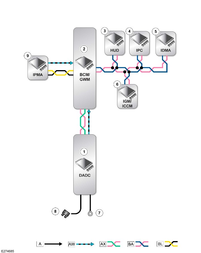
E274685

A = Hardwired: AM = BroadR-Reach®: AX = Flexray: BA = HS CAN HMI systems bus: BL = HS CAN underbody systems bus.

ItemDescription
1DADC
2Body Control Module (BCM)/Gateway Module A (GWM)
3HUD
4IPC
5IDMA
6IGM / ICCM
7Ground
8Power supply
9IPMA

Wade Aid (G2748512)

DESCRIPTION AND OPERATION

COMPONENT LOCATION

Component Location - 1 Of 1

NOTE:

The Right Hand Drive (RHD) vehicle is shown. The Left Hand Drive (LHD) vehicle is similar.
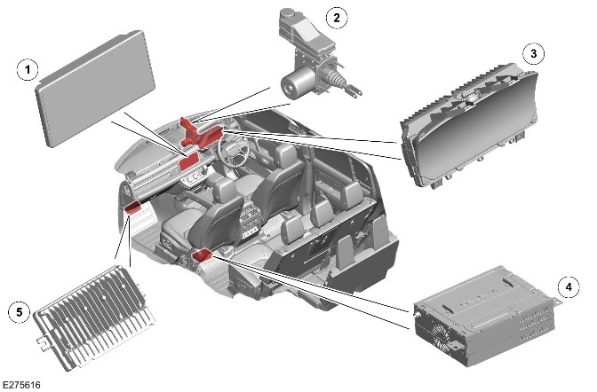
E275616

ItemDescription
1Interactive Display Module 'A' (IDMA)
2Integrated Power Brake
3
4>span class="acronym">Front Infotainment Control Module (IGM / ICCM)
5Near Field Sensing Module (NFSM)

Component Location - 2 Of 2

NOTE:

The LHD vehicle is shown. The RHD vehicle is similar.
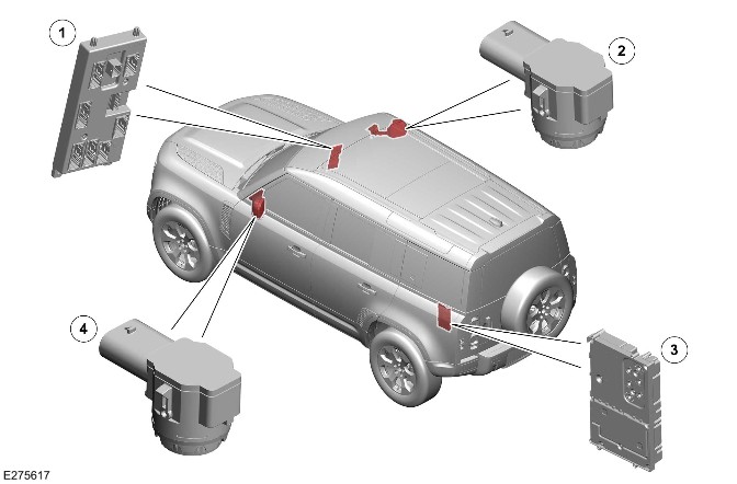
E275617

ItemDescription
1Body Control Module (BCM)/Gateway Module A (GWM)
2Wade sensor - Right
3Audio Amplifier Module (AAM)
4Wade sensor - Left

OVERVIEW

The wade sensing feature is designed to aid the driver to calculate the current depth when driving through water. The IDMA displays the current detected water level and the maximum wading depth of the vehicle.

The NFSM hosts the software to deliver the wade sensing functionality using 2 downward facing ultrasonic sensors installed in the door mirrors. The sensors connect to the NFSM and measure the distance to the water surface. From this measurement, the NFSM calculates the depth of the water when the vehicle is traveling.

DESCRIPTION

Near Field Sensing Module

NOTE:

The RHD vehicle is shown. The LHD vehicle is similar.

E275618

The NFSM is located below the instrument panel.

The NFSM has connections for the following:

  • Power
  • Ground
  • FlexRay
  • BroadR-Reach
  • Parking Aid sensor (quantity 8)
    • For additional information, refer to: Parking Aid (401-01 Parking Aid, Description and Operation).
  • Park Assist sensor (quantity 4)
    • For additional information, refer to: Parking Aid (401-01 Parking Aid, Description and Operation).
  • Wade sensing sensor (quantity 2)
  • Camera (quantity 4)
  • IGM / ICCM - Low-Voltage Differential Signalling (LVDS).

The NFSM receives the vehicle speed signal from the Anti-Lock Brake System Control Module (ABS) through the FlexRay.

The NFSM gathers the wade sensor signals. The calculated data is then relayed to the IDMA through the IGM / ICCM on the Automotive Pixel Link 2 (APIX2).

The NFSM provides a power supply and a ground for the wade sensing sensors.

Wade Sensing Sensor
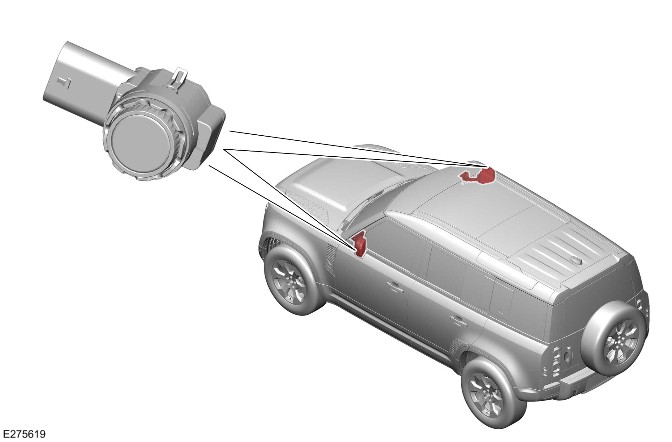
E275619

The wade sensing sensor is a downward facing ultrasound transducer. The sensor is used to estimate a wading depth of the water in which at least a portion of the vehicle is known to be disposed.

The wade sensing sensors provide information to the NFSM. The NFSM compares the data from the 2 wade sensing sensor located at an elevation greater than the threshold wading depth of the vehicle.

Interactive Display Module 'A'

NOTE:

The RHD vehicle is shown. The LHD vehicle is similar.

E274525

The IDMA communicates with other vehicle system through the High Speed (HS) Controller Area Network (CAN) Human Machine Interface (HMI) systems bus. The IDMA transfers the video data to the IGM / ICCM through the APIX2.

The IDMA displays the wading depth for the user.

OPERATION

CAUTIONS:

  • Do not assume that using the wade sensing feature reduces the risks of wading. The wade sensing feature only detects the immediate level of water that touches the vehicle. The wade sensing feature cannot detect or predict the depth of water around the vehicle or rapid increases in water level about to occur. At the same time, the wade sensing feature cannot predict if it is safe to continue driving. The user is responsible to assess the safety of the driving conditions, potential hazards and the current driving direction to avoid vehicle damage or personal injury.
  • Do not wade through flowing or rough water. This action can cause injury or death.
  • Do not wade through water if a layer of ice or snow exits on the water surface. The wade sensing system cannot detect the true level of the water, which can cause injury or death.
  • Do not use the wade sensing system for off road driving. Rapid increases in water depth cannot be detected in time to deliver a warning message to the user. This can cause injury or death.
  • The wade sensing sensor and the area below the sensors must be kept clean and free from snow, ice, mud and other debris. Failure to keep the sensors clean my result in sensor miscalculation.
  • The door mirrors must be in the normal (unfolded) position when using the wade sensing system. If the door mirrors are in the fold position, wade sensing system operates, but gives false readings.

NOTES:

  • The wade sensing system needs to be calibrated if the vehicle is installed with deployable side steps, fixed side steps or side tubes.
  • The wade sensing performance is improved when the vehicle suspension is set to the highest level. The wade sensing system does not operate correctly if the door mirrors are in fold position. The Parking Aid, Park Assist and stop/start systems are all disabled when the wade sensing system operates.

The NFSM incorporates software which is able to provide the wade sensing functionality. There are 2 ultrasonic sensors located on the underside of the door mirrors. The ultrasonic sensors are hardwired to the NFSM. The NFSM supplies the sensors with an ignition voltage and an earth lead connection. The sensors return a signal voltage, proportional to the measured reflection from the water. The water depth calculation is based on the reflection from the water surface, which is measured by the sensor and:

  • Height adjustment of the suspension from the Chassis Control Module (CHCM) through the FlexRay.
  • Depth effect of road gradient.

The NFSM uses these inputs when the vehicle moves through water to provide the user audible and visual information about:

  • The depth of water.
  • The gradient of the vehicle compared to the water level.

The wade sensing system can display the water depth information on the IPC and on the IDMA. The NFSM is connected with other vehicle systems through the FlexRay and the BroadR-Reach®.

The IDMA can display the current and maximum water depths. The wade sensing system warns the user as the maximum depth for wading approaches.

NOTE:

The background maybe have some differences. The icon and the messages are similar.
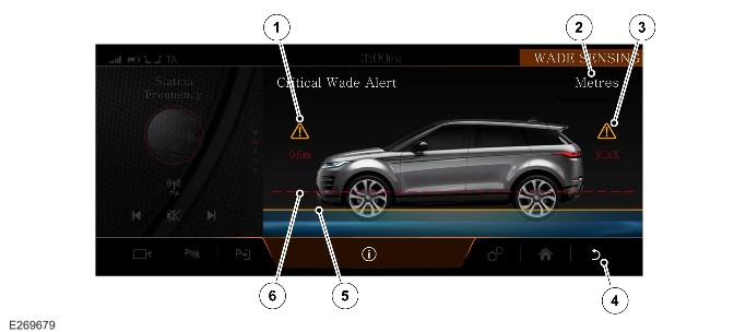
E269679

ItemDescription
1Depth indication numeral
2Units
3MAX warning
4Back soft key
5Depth indication line
6Maximum depth warning

The IDMA provides the user with the following information:

  • Initial wading advice.
  • Maximum vehicle wade depth.
  • Advice to select off road suspension height to support the maximum wade depth.
  • Ice wade warning, to prevent potential damage to the vehicle.
  • Road gradient - Level, nose down, nose up and laterally uneven.

The wade sensing system warns the user through the IDMA, IPC and audible tones, when the maximum depth approaches. If the wade sensing system limitations are exceeded, the IDMA view goes gray. The wade sensing system is suspended if the vehicle speed is greater than 16 km/h (10 mph). The wade sensing system re-actives automatically if the vehicle speed is less than 10 km/h (6 mph). If the vehicle speed is greater than 30 km/h (19 mph) for 30 seconds, the wade sensing system is switched OFF automatically.

CONTROL DIAGRAM

Control diagram - 1 Of 1
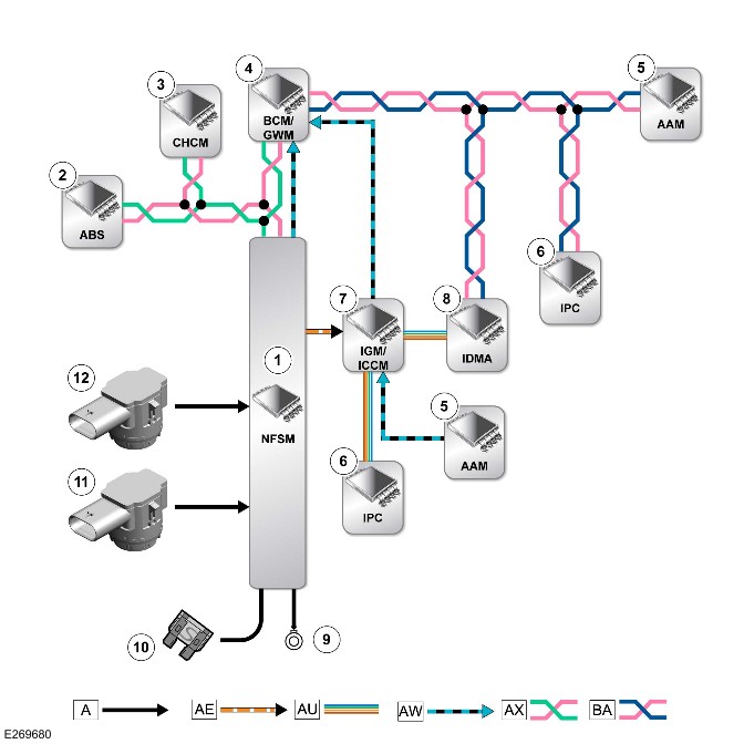
E269680

A = Hardwired: AE = LVDS: AU = APIX2: AW = BroadR-Reach®: AX = FlexRay: BA = HS CAN HMI systems bus.

ItemDescription
1NFSM
2ABS
3CHCM
4BCM/GWM
5AAM
6IPC
7IGM / ICCM
8IDMA
9Ground
10Power supply
11Wade sensing sensor - Left
12Wade sensing sensor - Right


Speed Control (G2748513)

DESCRIPTION AND OPERATION

COMPONENT LOCATION

Component Location - 1 of 1

NOTE:

A right hand drive (RHD) vehicle is shown. A left hand drive (LHD) vehicle is similar.
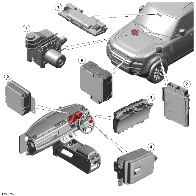
E275753

ItemDescription
1Image Processing Module (IPMA)
2Powertrain Control Module (PCM)
3
4Right steering wheel switchpack
5>span class="acronym">Driver Assistance Domain Controller (DADC)
6Cruise Control Module (CCM) - Vehicle with adaptive cruise control only
7Anti-Lock Brake System Control Module (ABS) - Part of the Integrated Power Brake

OVERVIEW

There are 4 variants of speed control available:

  • A cruise control system
  • An adaptive cruise control system
  • A speed limiter system
  • An adaptive speed limiter system.

The cruise control system maintains a set speed when the driver activates the cruise control. The cruise control can be suspended or canceled by a further input from the driver. The cruise control system is controlled by the DADC.

The adaptive cruise control system includes the same functionality as the cruise control system, but also has the ability to:

  • Automatically reduce vehicle speed, to less than the set speed, in order to maintain the selected time gap behind a slower moving vehicle.
  • Automatically increase the speed of the vehicle back to the set speed when it is safe to do so.
  • Alert the driver when a potential forward collision is detected within the detection area in front of the vehicle.

The speed limiter system restricts the vehicle speed to an adjustable preset maximum and prevents the vehicle exceeding that speed.

The adaptive speed limiter system reduces the vehicle speed to the maximum recommended for that particular road. The adaptive speed limiter system determines the speed limit by accessing data from the navigation system and the IPMA.

GENERAL SAFETY REGULATIONS 2 (market dependent)

The European Union have introduced General Safety Regulations 2 (GSR2). These are a set of mandatory regulations that require a number of Advanced Driver Assistance Systems (ADAS) be installed on GSR2 market vehicles to protect vehicle occupants, pedestrians, cyclists, and mitigate the human error that cause many accidents.

There must be the capability to record certain data for accident investigation. This data is stored in the DADC.

Required ADAS

  • Traffic Sign Recognition
  • Driver Condition and Attention Monitors
  • Autonomous Emergency Braking (AEB)
  • Emergency Lane Keep Assist
  • Blind Spot Monitor
  • Reverse Traffic Detection
  • Intelligent Speed Control
  • Emergency Stop Signal
  • Event Data Recorder

The GSR2 regulations also set out how these systems must warn the driver when the system is active, off, or in a fault state.

Warnings can be both visual and audible. The audible warning chime is heard through the vehicle infotainment system speakers.

The driver is able to switch a system OFF or ON through the 'Driver Assistance' menu with one press of a button on the steering wheel. The settings will change between 'High' (ON), 'Custom' and 'Low' on the IPC.

Alternatively the setting can be changed using the 'Driver Assistance' menu on the Interactive Display Module 'A' (IDMA) touchscreen.

NOTE:

Forward Collision Warning will never be switched off.

In GSR2 markets, these systems will default to 'High' (ON) after an ignition cycle, even if the driver has previously switched them OFF.

NOTE:

Non-GSR2 market vehicles will also have these ADAS installed, however, the system will not default ON, but instead retain the last driver setting across ignition cycles.

For additional information, refer to https://www.ownerinfo.landrove...

Driver assistance menu Instrument Panel Cluster Control Module B (IPCB)
E390052

ItemDescription
1Driver assistance mode switch
2Driver assistance mode display IPCB

Driver assistance menu IDMA
E390063

ItemDescription
1Low
2Custom
3High
4Speed Limit Warning
5Driver Attention Monitor (Camera - Driver Facing (C-DF))
6Forward Collision Warning

COUNTRIES AND TERRITORIES WITH GSR2 FEATURES

  • Andorra
  • Australia
  • Austria
  • Azores and Madeira
  • Belgium
  • Bulgaria
  • Croatia
  • Cyprus
  • Czech Republic
  • Denmark
  • Estonia
  • Finland
  • France
  • French Guyana
  • Germany
  • Greece
  • Guadeloupe
  • Hungary
  • Iceland
  • Iran
  • Israel
  • Italy
  • Latvia
  • Liechtenstein
  • Lithuania
  • Luxembourg
  • Malta
  • Martinique
  • Mayotte
  • Monaco
  • Netherlands
  • New Zealand
  • Norway
  • Palestine
  • Poland
  • Portugal
  • Republic of Ireland
  • Reunion
  • Romania
  • Slovakia
  • Slovenia
  • Spain
  • St Martin
  • Sweden
  • Switzerland
  • Turkey
  • United Kingdom

DESCRIPTION

Cruise Control Switches

NOTE:

A RHD vehicle is shown, vehicle is similar.
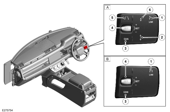
E275754

ItemDescription
AVehicles with adaptive cruise control
BVehicles with cruise control
1Speed limiter switch
2Time gap increase switch - Vehicle with adaptive cruise control only
3'Cancel' switch - Disengage the cruise control
4Rocker switch - Engage the cruise control, increase the set speed, decrease the set speed and resume the canceled set speed
5Steering assist switch - Vehicle with adaptive cruise control only
6Time gap decrease switch - Vehicle with adaptive cruise control only

The cruise control switches are located on the right steering wheel switchpack. There is a sub harness on the steering wheel which connects the switches to the clockspring. The cruise control switches consist of the capacitive touch switches and the rocker switch. The following functions are selected by pressing the cruise control switches:

  • Cruise control system
  • Adaptive cruise control system
  • Speed limiter system.

Cruise control system

The cruise control function is hosted by the DADC. The DADC calculates the amount of acceleration or deceleration required to control the vehicle speed and sends a request to the ABS. The ABS sends a request for engine torque control to the PCM. The ABS also sends a request for braking, which is handled internally within the ABS.

The following cruise control switches on the right steering wheel switchpack are used to operate the cruise control system:

  • Rocker switch
    • 'SET +'
    • 'SET -'
    • 'RES'.
  • 'Cancel' switch
  • Speed limiter switch.

The cruise control warning indicator in the IPC illuminates when cruise control is engaged.

Speed Control Warning Indicator
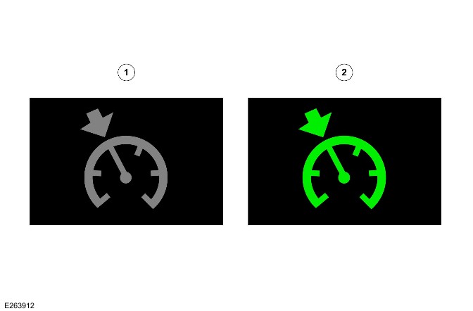
E263912

ItemDescription
1Cruise control in 'STANDBY' or 'FAULT' state with follow mode OFF
2Cruise control in 'ACTIVE' or 'SUSPEND' state with follow mode OFF

During cruise control operation, the cruise control system can be used to accelerate the vehicle without using the accelerator pedal.

The driver can also intervene by using the brake or accelerator pedals at any time.

Adaptive cruise control system

NOTE:

The adaptive cruise control system is intended for use in specific driving situations. The adaptive cruise control system does not remove control and responsibility from the driver.

The adaptive cruise control system allows the driver to set a cruising speed for the vehicle. The vehicle speed is automatically reduced when a slower moving vehicle is detected in the lane ahead. The system then maintains a constant gap to the vehicle ahead. When the system detects that the slower moving vehicle is no longer present, it automatically raises the vehicle speed back to the set speed.

The adaptive cruise control system comprises the following features to operate effectively:

  • Follow mode
  • Queue assist
  • Stop and go
  • Steering assist.

The adaptive cruise control switches are the same as used for the cruise control system, with the following:

  • The addition of 2 time gap switches
  • A steering assist switch.

The time gap switches allow the driver to adjust the follow mode function to 1 of 4 pre-set time gaps. The 4 pre-set time gaps are the following:

  • Gap 1 = 0.8 second
  • Gap 2 = 1.3 seconds
  • Gap 3 = 1.8 seconds
  • Gap 4 = 2.3 seconds.

The selected time gap is displayed in the IPC message center when the time gap switches are operated.

When the adaptive cruise control is engaged, the switches adjust the follow mode time gap. The default setting for the follow mode time gap is 1.8 seconds when in Power Mode 7 (engine running).

Speed limiter system

The speed limiter is a driving aid only.

The speed limiter does not operate when cruise control or adaptive cruise control is engaged. The speed limiter switch enables the driver to select cruise control mode or speed limiter mode.

There are 2 types of speed limiter:

  • Speed limiter - Allows the driver to manually restrict the maximum vehicle speed.
  • Adaptive speed limiter - Works in conjunction with the Traffic Sign Recognition (TSR) system and the navigation system to restrict the maximum vehicle speed.

The speed limiter system is activated through the 'LIM' switch on the right steering wheel switchpack.

When the speed limiter mode has been activated, selection of the speed limiter or adaptive speed limiter can be made by:

  • Pressing and holding the 'Cancel' switch for 4 seconds.
  • The Touchscreen.

Cruise Control Module
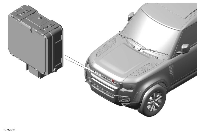
E275632

The CCM is located behind the left of the radiator grille. The CCM bracket is installed to the radiator grille with 4 bolts.

The CCM contains a forward looking radar transceiver together with related controlling hardware and software. A High Speed (HS) Controller Area Network (CAN) Underbody systems bus connection allows the CCM to communicate with other system control modules. Power supply to the CCM is from the relay in the Rear Junction Box (BCMB).

The CCM is active whenever in Power Mode 6 (ignition ON), even when cruise control is not engaged. The forward alert and AEB functions also use the CCM. In Power Mode 6 (ignition ON), the CCM is electrically powered, but no radar transmissions are emitted until in Power Mode 7 (engine running).

The CCM transmits a radar beam forward of the vehicle and detects the returning signals reflected off other vehicles and objects ahead. The radar operates at millimetric wavelengths (76 - 77 GHz) and transmits a frequency modulated continuous wave signal at a relatively low power level. The CCM detects the range, relative velocity and angle of objects within the scanned arc up to a maximum distance of 140 m (500 feet). The horizontal scanned arc is 20° wide and centered on the longitudinal axis of the vehicle. The vertical scanned arc is 10° high and centered on a nominal position.

The CCM compares vehicle speed data from the ABS with the relative speed of an external object. The speed of the objects is detected by the radar to determine that the object is stationary or not. When tires are equipped which are different in diameter from those specified for the vehicle it may cause an incorrect road speed to be calculated. The ABS calculates the vehicle speed. The incorrect information may cause stationary objects to be falsely identified as moving vehicles. The detection of falsely moving vehicles may result in the speed of the sensing vehicle decreasing.

The CCM continuously monitors both moving vehicles and stationary objects to determine if it can 'see' normally. There are situations when the CCM may determine that it is blocked:

  • When the CCM can detect only a few objects.
  • When physically covered or obstructed, for example, by an accumulation of snow or mud on the radiator grille.
  • When traveling through a tunnel or in complex traffic situations.

The CCM then inhibits adaptive cruise control and records a Diagnostic Trouble Codes (DTC). The adaptive cruise control system resets within the same ignition cycle. In this case the CCM does not have a fault and must not be replaced.

The CCM does not require mechanical alignment when it is replaced in service. Horizontal and vertical alignment is achieved by putting the CCM into service alignment mode using the Jaguar Land Rover (JLR) approved diagnostic equipment. The vehicle then needs to be driven for a short period while the CCM does a calibration routine. Calibration is complete when the follow mode warning indicator in the IPC stops flashing.

The service alignment process measures the path of stationary targets. For example, streetlights, railings, road signs and parked vehicles. The service alignment process uses this data to correct for mechanical misalignment.

Alignment completes more quickly when more suitable targets are available.

The following recommendations help:

  • The speed must be above 40 km/h (25 mph).
  • Try to keep the speed constant. The process takes longer to complete when the speed is not constant.
  • Select a road with plenty of stationary objects. For example, lamp posts, railings, street signs or parked vehicles. Use an inside or outside lane.
  • Following vehicles too closely obscures the stationary targets from the radar, a time gap of at least 2 seconds is recommended.

Image Processing Module 'A'

NOTE:

General Safety Regulations 2 (GSR2) markets require that the field of view in front of the IPMA must be equipped with a de-icing element to allow correct operation in cold conditions.
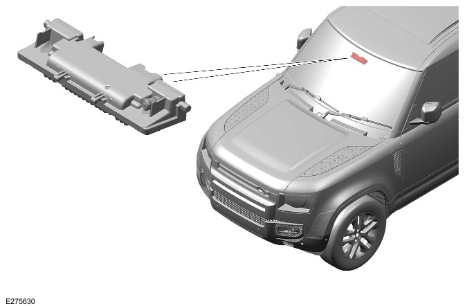
E275630

The IPMA is located below the rear view mirror. The IPMA uses the forward facing cameras to scan the road ahead. The information is shared with the DADC to operate the function of the adaptive cruise control. The IPMA sends the information on the HS CAN Underbody systems bus.

Driver Assistance Domain Controller

NOTE:

A RHD vehicle is shown, A LHD vehicle is similar.
E275629

The DADC is located behind the right of the instrument panel.

The DADC has connections for the following:

  • Power supply
  • Ground
  • FlexRay
  • Private CAN bus
  • HS CAN Underbody systems bus.

The DADC receives the information from the CCM and the IPMA to operate the cruise control.

Powertrain Control Module

The PCM is located on the left of the engine compartment behind the front left wheel arch.

The PCM receives inputs from various sensors and outputs reference voltages and signal information to other sensors and actuators for power control.

For additional information, refer to:

Electronic Engine Controls (303-14 Electronic Engine Controls - INGENIUM I6 3.0L Diesel, Description and Operation),
Electronic Engine Controls (303-14 Electronic Engine Controls - INGENIUM I6 3.0L Petrol, Description and Operation),
Electronic Engine Controls - INGENIUM I4 2.0L Petrol (303-14 Electronic Engine Controls - INGENIUM I4 2.0L Petrol/INGENIUM I4 2.0L Petrol - PHEV, Description and Operation),
Electronic Engine Controls - INGENIUM I4 2.0L Petrol - PHEV (303-14 Electronic Engine Controls - INGENIUM I4 2.0L Petrol/INGENIUM I4 2.0L Petrol - PHEV, Description and Operation),
Electronic Engine Controls (303-14 Electronic Engine Controls - INGENIUM I4 2.0L Diesel, Description and Operation).

OPERATION

Cruise Control

Cruise control is engaged by pushing upward the rocker switch ('SET +'). Cruise control can be engaged from any speed (even stationary) with a minimum set speed of 15 km/h (10 mph). When cruise control is engaged, the IPC illuminates the cruise control warning indicator and the set speed is displayed in the message center.

Increase cruise control speed

The speed can be increased by 1 of 3 methods:

  • Push upward and hold the rocker switch ('SET +') which causes the vehicle to accelerate. When the switch is released the attained speed is set as the control speed.
  • Repeatedly pushing upward the rocker switch ('SET +'). Each operation increases the vehicle speed by 2 km/h (1 mph).
  • Use the accelerator pedal to increase the vehicle speed. When the required speed is reached, a single press of the rocker switch ('SET +') sets the cruise control speed.

Cruise control adjustment may be changed at the current vehicle speed. The speed adjustment does not occur when the rocker switch ('RES') is pressed or when the vehicle speed is noticeably different to the set speed. This is noticeable when resuming cruise control and a large difference exists between the set speed and the current speed. The driver can set a new speed, but cannot adjust the old speed.

Decrease cruise control speed

The set speed can be decreased by the operation of pushing downward and holding the rocker switch ('SET -') until the required speed is reached. When the switch is released the speed is reset at that value. The set speed can be decreased incrementally by the operation of pushing downward and releasing the rocker switch ('SET -'). Each operation decreases the speed by 2 km/h (1 mph).

Suspend cruise control

Cruise control is automatically suspended when the following conditions apply:

  • A door is opened (any door except tailgate).
  • The brake pedal is pressed.
  • The 'Cancel' switch is operated.
  • PARK (P), NEUTRAL (N) or REVERSE (R) is selected.
  • The Electric Park Brake (EPB) is applied.
  • When the driver presses the accelerator pedal to override the cruise control, and the set speed is exceeded for more than 1 minute.
  • The ABS requests a cruise control cancellation.
  • The Hill Descent Control (HDC) is activated.
  • The speed limiter is in operation.
  • All Terrain Progress Control (ATPC) is activated.

In all suspend events, except when the driver door is opened, the memory speed is retained. A single operation of the rocker switch ('RES') resumes cruise control at the previously set speed.

The right steering wheel switchpack transmits the data to the Body Control Module (BCM)/Gateway Control Module (GWM) through the Steering Wheel Module (SWM). The BCM/GWM communicates with the SWM on the Local Interconnect Network (LIN). The BCM/GWM then passes the data onto the FlexRay and to the HS CAN Underbody systems bus.

The cruise control system uses inputs from the following:

  • Accelerator Pedal Position (APP) sensor
  • PCM
  • ABS.

Adaptive Cruise Control

WARNING:

The adaptive cruise control system is not an impact warning or avoidance system. At all times the driver must be prepared to intervene to control the vehicle speed.

Adaptive cruise control operation is similar to the cruise control system for engaging, suspending and resuming cruise control.

The main differences between the 2 systems:

  • The adaptive cruise control remains engaged at a vehicle speed of less than 15 km/h (10 mph).
  • The adaptive cruise control uses the brakes to slow the vehicle, to a stop if necessary.

The adaptive cruise control system utilizes the following main components:

  • CCM
  • IPMA
  • Parking Aid sensors (quantity 8)
  • Park Assist sensors (quantity 4)
  • Right steering wheel switchpack
  • PCM
  • Electric throttle
  • ABS
  • Adaptive cruise control warning indicator - Displayed in the IPC.

The adaptive cruise control system uses a forward looking radar sensor, integrated into the CCM. The radar sensor scans the road ahead and looks for objects that are moving at a different speed to the sensing vehicle speed. When a target is identified, the adaptive cruise control system monitors the time gap between the sensing vehicle and the target vehicle.

When the gap is less than the set driver selected level, the adaptive cruise control system intervenes until the correct time gap is attained. The adaptive cruise control system slows the vehicle by reducing the throttle and/or applying the brakes. The driver can select between 4 time gap settings. The chosen setting is displayed in the IPC.

The adaptive cruise control system detects but does not react to the following:

  • Vehicles in the oncoming lane
  • Stationary vehicles
  • Pedestrians.

The adaptive cruise control system also uses the IPMA camera to scan the road ahead. The IPMA sends object detection data to the DADC. The purpose is to improve the tracking and classification of vehicles and other targets, for instance detection of vehicles changing lanes and stopped vehicles. The adaptive cruise control system therefore brings the vehicle to a halt behind stopped vehicles in low speed queuing. For Example: At multi-lane traffic lights. The cruise control system does not brake for stationary vehicles when the vehicle speed is greater than 30 km/h (20 mph). When the camera is not available the system continues to operate on radar data only.

The adaptive cruise control system allows the following additional features:

  • Auto resume (no pedal press required) when the lead vehicle moves off within 3 seconds of stopping.
  • An audible warning when a pedestrian is detected within 1 meter in front of the vehicle during the restart.
  • Automatic engine restart during queue assist when the vehicle ahead moves off.
  • Update of the adaptive cruise control warning indicator with lead vehicle position display.

The adaptive cruise control is active at a minimum set speed of 15 km/h (10 mph). The adaptive cruise control is active up to the maximum vehicle speed with a maximum set speed of 200 km/h (124 mph). The adaptive cruise control system only functions when a set speed is entered through the operation of the rocker switch ('SET +'). The adaptive cruise control system only intervenes with the set speed when it detects a target vehicle. The adaptive cruise control system reduces the sensing vehicle speed when the time gap is less than the selected time gap.

The PCM and fuel injection control are unchanged from those used for the cruise control system.

Adaptive Cruise Control System Restrictions

The adaptive cruise control system is only intended to provide enhanced cruise control in certain specific conditions. The following illustration shows circumstances where the adaptive cruise control system may brake late or unexpectedly. The driver is required to intervene in these situations.
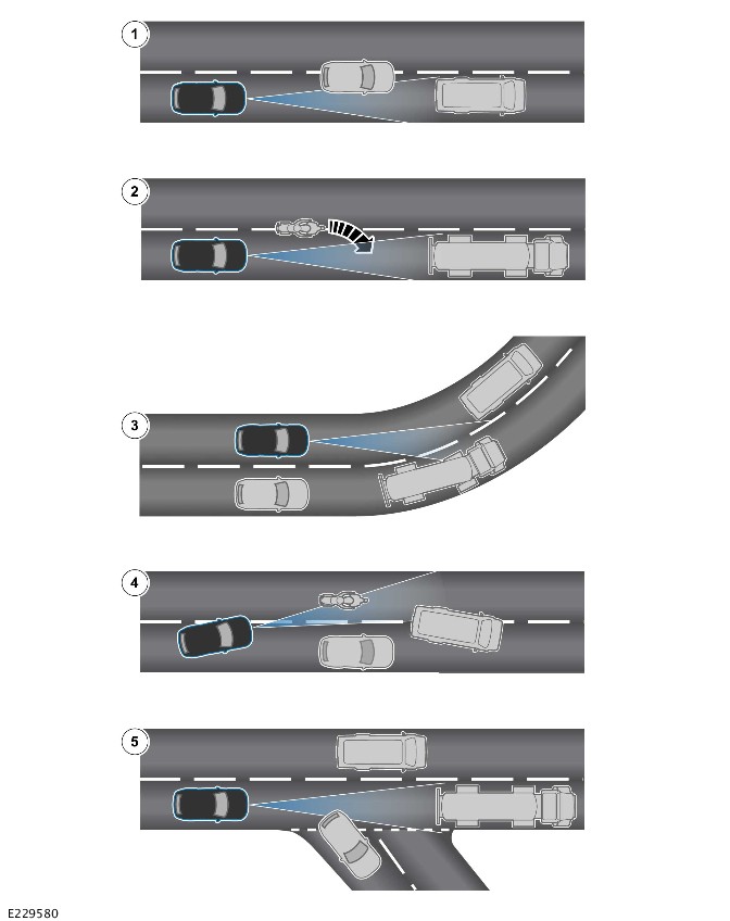
E229580

ItemDescription
1Driving on a different line to the vehicle in front
2Vehicles that merge into the same lane are only detected when they have moved fully into the lane
3On bends in the road there can be issues with detection of the vehicle in front when going into and coming out of a bend
4Moving around a stationary vehicle may cause uncertainty regarding which vehicle is being followed
5A vehicle in front moving out of your lane may cause uncertainty regarding which vehicle is being followed

On the approach to a bend or exit from a bend, a target vehicle may be lost or a new target may be sensed. The change is due to the vehicles ahead changing their angular position with respect to the CCM. The sensing vehicle losing the target vehicle causes the sensing vehicle to increase speed to the set speed. The acceleration is undesirable either on a bend in the road, or entering a bend in the road when the target is suddenly lost.

Speed Limiter

The speed limiter icon illuminates when the speed limiter is activated by pressing the 'LIM' switch. The selected speed is displayed in the IPC.

The system speed is set using the rocker switches ('SET +' and 'SET -') as the following:

  • Push upward and hold the rocker switches ('SET +') to increase the speed limiter set speed in 10 km/h (5 mph) steps.
  • Push upward and release the rocker switches ('SET +') to increase the speed limiter set speed by 2 km/h (1 mph).
  • Push downward and hold the rocker switches ('SET -') to decrease the speed limiter set speed in 10 km/h (5 mph) steps.
  • Push downward and release the rocker switches ('SET -') to decrease the speed limiter set speed by 2 km/h (1 mph).

The speed limiter can be suspended by operating the 'Cancel' switch. The speed limiter can be resumed at the previously used set speed by operating the rocker switch ('RES'). The speed limiter can resume when the vehicle speed is a maximum of 30 km/h (20 mph) above the previous set speed.

When the vehicle speed is too high to resume the speed limiter operation, 'TOO FAST TO RESUME' is displayed in the IPC message center.

The speed limiter system allows full driver control of the vehicle speed up to the set speed. The speed limiter restricts the vehicle speed and does not allow the speed to go over the set limit. When the driver fully depresses the accelerator pedal the speed limiter is temporarily overridden.

Adaptive Speed Limiter

The adaptive speed limiter icon illuminates when the adaptive speed limiter has been selected. The adaptive speed limiter restricts the vehicle maximum speed to the current legal applicable road speed limit. The speed limit information is provided by the navigation system and TSR. When a valid speed limit is not available, the adaptive speed limiter is deactivated and the limiter defaults to the speed limiter.

The adaptive speed limiter system only responds to speed settings between 15 km/h (10 mph) and 150 km/h (93 mph). Below the speed range a message, 'SET POINT OUT OF RANGE' is displayed in the message center. If TSR above the maximum speed limit range, the adaptive speed limiter sets the speed limiter to unlimited.

Adjustment maximum of 10 km/h (5 mph) above and below the legal speed limit, can be set by operating the rocker switches. When a legal speed limit is detected higher or lower than the current vehicle speed, the adaptive speed limiter adjusts the speed at safe level.

When the vehicle speed exceeds the speed limit by more than 3.5 km/h (2.2 mph), a warning displays in the message center. When the speed exceeds the speed limit by 7 km/h (4.4 mph) for more than 4 seconds, a chime sounds.

Operating the 'Cancel' switch puts the adaptive speed limiter into standby mode. The adaptive speed limiter can be reactivated by operating the rocker switch ('RES').

When the driver fully depresses the accelerator pedal, the adaptive speed limiter is overridden.

When the vehicle is equipped with speed limiter and adaptive speed limiter systems:

  • When the speed limiter system was in use when the ignition was turned OFF, the selected speed limiter mode is saved. The speed limiter is activated again when the ignition is switched back ON. However the speed settings are not remembered and have to be set again.
  • When the adaptive speed limiter system was in use when the ignition was turned OFF, the speed limiter setting is remembered across drive cycles. When the ignition is turned back ON, the adaptive speed limiter remains enabled.

Follow Mode

A set speed is selected and this speed is maintained until a slower vehicle is encountered in the lane ahead. When the vehicle ahead comes within the effective range of the CCM radar, the system identifies it as a target vehicle. When the distance between the 2 vehicles closes to the set time gap, the CCM reduces engine speed. The CCM applies the brakes to maintain the set time gap when it is necessary.

To indicate that the system is in follow mode:

  • The follow mode warning indicator illuminates in the IPC.
  • The current time gap setting is displayed in the message center.
Follow Mode Warning Indicator
E251026

Automatic braking is limited to approximately 30% of full pressure (0.3g deceleration). This is intended to provide a smooth, gradual deceleration in follow mode conditions.

Follow mode is effectively a closed loop system. When several vehicles are ahead, the closest vehicle is chosen as the target to follow.

The system exits follow mode and extinguishes the follow mode warning indicator:

  • When the target vehicle moves out of the CCM radar range.
  • When either vehicle changes lane.

The adaptive cruise control system then increases vehicle speed back to the original set speed.

Queue Assist Mode

When the target vehicle comes to a halt, the CCM reduces engine speed and applies the brakes. The CCM halts the sensing vehicle and suspends cruise control operation when adaptive cruise control is engaged.

When stationary, the CCM applies the EPB when 1 of the following occurs:

  • Adaptive cruise control is disengaged with the 'Cancel' switch.
  • The driver seatbelt is unbuckled.
  • The driver door is opened.

When the target vehicle moves away, the cruise control operation can be resumed by:

  • Pressing the accelerator pedal for a minimum of 0.5 second.
  • Operating the rocker switch ('RES').

The sensing vehicle then follows the target vehicle in follow mode or until it stops again. When the sensing vehicle can no longer detect a target, the vehicle increases speed to the set speed.

Follow Mode Off

The driver may select follow mode OFF when it is desired. The mode engages speed without reacting to vehicles ahead, or when a blockage is detected which inhibits normal operation. When the follow mode is selected OFF, the CCM does not react to vehicles ahead.

The follow mode can be disabled by pressing and holding the gap decrease switch on the right steering wheel switchpack. Press the switch until the 'Follow Mode Off' message is displayed. The follow mode OFF warning indicator is then displayed in the message center.

NOTE:

Follow mode ON is the default setting for adaptive cruise control. Follow mode OFF is automatically canceled when the ignition is switched OFF.

By pressing and holding the follow mode gap increase switch to switch the follow mode ON. The previous gap settings resume and the follow mode warning indicator illuminates.

Forward Alert

NOTE:

The system is intended as a driver aid and must be used as such. The system is NOT an impact warning or avoidance device.

When a potential forward collision is detected within the detection area in front of the vehicle:

  • An audible warning tone is emitted from the speakers.
  • A warning message is displayed in the message center.

There are 4 forward alert sensitivity settings available:

  • OFF
  • Very early
  • Early
  • Normal.

Forward alert does not initiate any direct action, the driver must take the appropriate action when the message is displayed in the message center. The system monitors driver intervention and may not issue the warning when the driver has taken the appropriate action (braking, steering or indicating) early enough.

The sensitivity of the forward alert system can be changed through the touchscreen when the adaptive cruise control is not engaged. Confirmation of the gap change is given in the message center. The forward alert function recalls the last selected sensitivity setting when in Power Mode 7 (engine running).

Autonomous Emergency Braking

The AEB system detects targets within the detection area in front of the vehicle. The AEB system is hosted within the DADC. The AEB system uses the IPMA and the CCM for object detection and classification. The AEB system is only activated when the vehicle is moving forward.

For additional information, refer to: Autonomous Emergency Braking (401-03 Braking Aid, Description and Operation).

Diagnostics

The DADC, IPMA and CCM record any DTCs and related data. Read the DTCs and related data with the JLR approved diagnostic equipment.

The JLR approved diagnostic equipment can read live data and activate certain components.

CONTROL DIAGRAM

Control Diagram - 1 of 2 - Cruise Control
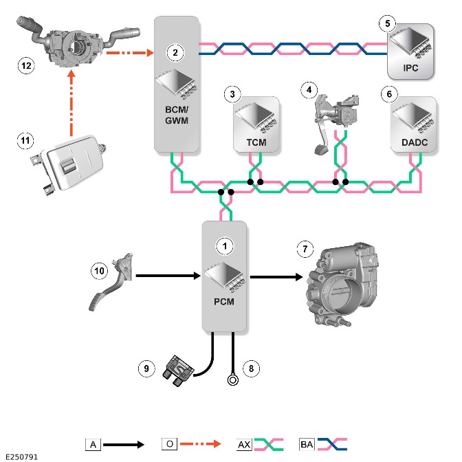
E250791

A = Hardwired: O = LIN: AX = FlexRay: BA = HS CAN Human Machine Interface (HMI) systems bus.

ItemDescription
1PCM
2BCM/GWM
3Transmission Control Module (TCM)
4Integrated Power Brake
5IPC
6DADC
7Electric throttle
8Ground
9Power supply
10APP sensor
11Right steering wheel switchpack
12SWM

Control Diagram - 2 of 2 - Adaptive Cruise Control
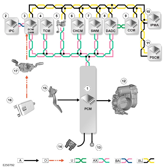
E250792

A = Hardwired: O = LIN: U = Private CAN bus: AW = BroadR-Reach®: AX = FlexRay: BA = HS CAN HMI systems bus: BL = HS CAN Underbody system bus.

ItemDescription
1DADC
2BCM/GWM
3Head Up Display (HUD)
4IPC
5IDMA
6PCM
7ABS
8IPMA
9CCM
10Ground
11Power supply
12Right steering wheel switchpack
13SWM with Steering Angle Sensor Module (SASM)
14Electric power steering
15Transfer Case Control Module (TCCM)
16TCM
17Power Steering Control Module (PSCM)

Driver Assistance Domain Controller (G2748514)

REMOVAL AND INSTALLATION

  • 86.54.71
  • Driver Assistance Domain Controller (DADC) - renew
  • Right hand drive
  • 0.20
  • USED WITHINS

Removal

NOTES:

  • This procedure contains some variation in the illustrations depending on the vehicle specification, but the essential information is always correct.
  • This procedure contains illustrations showing certain components removed to provide extra clarity.

The following step(s) applies to:
All vehicles

  1. Disconnect the 12 V system.Refer to: 12V System Disconnect and Connect (414-00 Battery and Charging System - General Information, General Procedures).
  2. E272563
    • Remove the 3 bolts.
    • Reposition the footwell trim panel away from the instrument panel lower trim.
  3. E272564
    • Disconnect the electrical connector.
    • Remove the footwell trim panel.

The following step(s) applies to:
Right hand drive vehicles

  1. E272657
    • Disconnect the electrical connector.
    • Remove the 3 nuts.
    • Remove the accelerator pedal assembly.
  2. E272658
    • Release the clip.
    • Reposition the wiring harness away from the brake pedal and bracket.
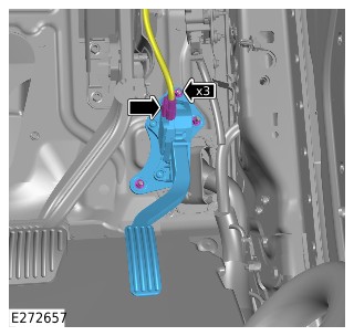
The following step(s) applies to:
All vehicles

  1. E272565
    • Disconnect the electrical connector.
    • Remove the 3 nuts.
    • Remove the Driver Assistance Domain Controller (DADC).
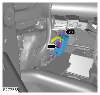
Installation

The following step(s) applies to:
All vehicles

    • Install the DADC.
    • Install and tighten the 3 nuts.Torque: 10Nm
    • Connect the electrical connector.

The following step(s) applies to:
Right hand drive vehicles

    • Reposition the wiring harness into the correct location.
    • Install the clip.
    • Install the accelerator pedal assembly.
    • Install and tighten the 3 nuts.Torque: 10Nm
    • Connect the electrical connector.

The following step(s) applies to:
All vehicles

    • Connect the electrical connector.
    • Install the footwell trim panel.
    • Install and tighten the 3 bolts.Torque: 5Nm
  1. Connect the 12 V system.Refer to: 12V System Disconnect and Connect (414-00 Battery and Charging System - General Information, General Procedures).
  2. If a new component has been installed, use Jaguar Land Rover (JLR) approved diagnostic equipment to configure. SRO 858658 Driver Assistance Domain Controller - Update - Replace ECU to be claimed separately.


Autonomous Emergency Braking (G2749279)

DESCRIPTION AND OPERATION

Component Location

NOTE:

Right Hand Drive (RHD) variant shown, Left Hand Drive (LHD) variant is similar.
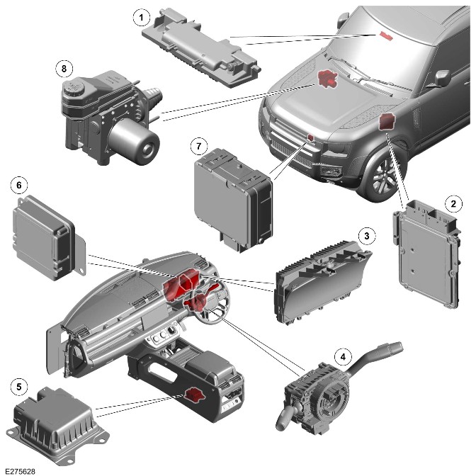
E275628

ItemDescription
1Image Processing Module 'A' (IPMA)
2Powertrain Control Module (PCM)
3
4>span class="acronym">Steering Angle Sensor Module (SASM) in the Steering Wheel Module (SWM)
5Restraints Control Module (RCM)
6Driver Assistance Domain Controller (DADC)
7Cruise Control Module (CCM)
8Integrated Power Brake

Overview

WARNING:

Collision avoidance systems are not a substitute for driving safely, with due care and attention. Staying alert, driving safely, and being in control of the vehicle at all times is the responsibility of the driver. If the Autonomous Emergency Braking (AEB) brings the vehicle to a stop, the brakes continue to hold the vehicle stationary for a few seconds. After this period, the driver must resume full control of the vehicle. Failure to take back full control of the vehicle could result in an accident, leading to serious injury or death.

Many accidents are caused by braking late and braking with insufficient force. With AEB the system acts autonomously, independently of the driver to avoid or mitigate the accident.

The AEB is an active-control feature. AEB provides the situational awareness and aids the driver through collision warnings by visual, audio and haptic warnings and through Advanced braking. AEB helps to avoid or mitigate the collision by braking for stationary, moving and decelerating targets in city urban and city inter-urban scenarios.

The AEB uses the forward facing camera located above the rear view mirror and a forward facing radar located on the front bumper. The camera and radar are used to help identify an imminent risk of collision with:

  • Another vehicle traveling in front.
  • An oncoming vehicle from an adjacent lane while the host vehicle is turning left or right.
  • A crossing pedestrian.
  • A pedestrian moving in the same direction as the vehicle.
  • An oncoming pedestrian from the opposite direction while the host vehicle is turning left or right.
  • A crossing cyclist.
  • A cyclist traveling in the same direction as the vehicle.
  • An oncoming cyclist from the opposite direction while the host vehicle is turning left or right.

If there is a possible collision, the driver is alerted by a visual, audible and haptic warning signal. If driver does not intervene, the system applies full or partial braking power to stop the vehicle or slows it down significantly to mitigate the severity of the collision. It supports driver by additional brake support if driver applies insufficient brake to avoid collision. The system operates up to a vehicle speed of 130 km/h (80 mph).

Following an automatic activation of the brakes, AEB will request a message to be displayed to the driver. The message informs the driver that:

  • An AEB event has taken place.
  • The vehicle is being held for a few seconds after stopping.

The AEB works by measuring the distance to any vehicle in front and then reacts if that distance shortens suddenly. The AEB system uses the IPMA and the CCM for object detection and classification. The braking control is applied by the Integrated Power Brake system.

Description

Integrated Power Brake
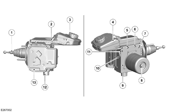
E267002

ItemDescription
1Input rod and pedal interface
2Brake fluid level sensor electrical connector
3Brake fluid reservoir cap
4Brake fluid reservoir
5Front left brake outlet port
6Front right brake outlet port
7Rear left brake outlet port
8Electric motor
9Hydraulic Control Unit (HCU)
10Internal brake master cylinder
11Rear right brake outlet port
12Pedal feel simulator
13Integrated Power Brake control module

The Integrated Power Brake control module uses the HCU to modulate hydraulic pressure to the individual wheel brakes to control the brake functions. The Anti-Lock Brake System Control Module (ABS) handles the AEB braking event to avoid/mitigate collision. The ABS provides the vehicle speed, wheel speed, pitch angle, roll angle, terrain information, Dynamic Stability Control (DSC) activity and traction control activity that will be used to suppress or cancel AEB requests.

The ABS is a function of the Integrated Power Brake control module as internal software.

The brake pressure is modulated separately for each wheel in order to maintain vehicle stability.

When required, the ABS actively intervenes and operates the HCU during braking or vehicle maneuvers to correct the vehicle attitude, stability, traction or speed. During incidents of vehicle correction, the Integrated Power Brake control module may request the PCM to control engine power in order to further stabilize and correct the vehicle.

The Integrated Power Brake control module processes the information received from the sensors according to defined control algorithms. The results of these calculations are sent to the HCU. The HCU increases and decreases the pressure in the brakes of the vehicle according to the functional requirements.

The pressure sensors in the simulator and plunger circuits provide the Integrated Power Brake control module with hydraulic pressure signals. The contact pins on the HCU mate with contacts on the ABS to provide the electrical connections from the Integrated Power Brake control module to:

  • The plunger motor
  • The pressure sensors.

To provide full system functionality, the Integrated Power Brake system comprises the following components and programs:

  • The Integrated Power Brake.
  • The DSC switch.
  • The combined Hill Descent Control (HDC) and All Terrain Progress Control (ATPC) switch.
  • The 4 wheel speed sensors.
  • The SASM.
  • The PCM.
  • The RCM.
  • The DADC.
  • The Body Control Module (BCM)/Gateway Module A (GWM).
  • The IPC warning indicators.

The Integrated Power Brake system provides the following brake functions that are designed to assist the vehicle or aid the driver:

  • ABS
  • Roll Stability Control (RSC)
  • Corner Brake Control (CBC)
  • DSC
  • Electronic Brake Force Distribution (EBD)
  • Electronic brakeprefill
  • Electronic Traction Control (ETC)
  • Emergency Brake Assist (EBA)
  • AEB
  • Engine Drag-torque Control (EDC)
  • Enhanced understeer control
  • Gradient acceleration control
  • Gradient release control
  • Terrain Response system integration
  • HDC
  • Hill launch assist
  • Trailer stability assist.

For additional information, refer to: Integrated Power Brake System (206-08 Brake Controls and Actuation, Description and Operation).

DRIVER ASSISTANCE DOMAIN CONTROLLER

E275629

The DADC is located behind the right of the instrument panel.

The DADC processes the information coming from the external sensing and vehicle system component in order to decide if or not the collision or accident becomes imminent. In this case, AEB requests the maximum available emergency braking which can be provided by the vehicle at the moment when the request is generated. The emergency braking is to avoid or mitigate the collision. The AEB issues warning messages to the driver whenever it is necessary.

The following features are hosted in DADC:

  • Lane Keep Assist (LKA)
  • Blind spot assist
  • Speed limiter
  • Adaptive speed limiter
  • Cruise control
  • Adaptive cruise control
  • Traffic Sign Recognition (TSR).

The DADC has connections for the following:

  • Power
  • Ground
  • FlexRay
  • High Speed (HS) Controller Area Network (CAN) Underbody systems bus
  • BroadR-Reach®.

The DADC receives the information from the CCM and the IPMA to operate the cruise control.

IMAGE PROCESSING MODULE 'A'

E275630

The IPMA is located centrally at the top of the windshield, behind the rear view mirror cover. The IPMA is attached to a bracket, which is bonded to the windshield.

The information is shared with the DADC and the Integrated Power Brake to operate the AEB function. The IPMA receives an ignition supply from the Engine Junction Box (EJB). Information can be exchanged from the IPMA through the BroadR-Reach® to the BCM/GWM which then re-directs the necessary signals to the other modules as required. The IPMA is connected to the HS CAN Underbody systems bus from which it receives necessary information to compute object detection correctly.

The IPMA has connections for the following:

  • Power
  • Ground
  • FlexRay
  • HS CAN Underbody systems bus
  • BroadR-Reach®.

INSTRUMENT PANEL CLUSTER
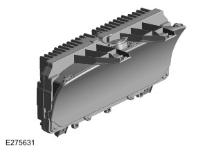
E275631

The IPC is located in driver side of the instrument panel. All displays are virtual gauges with the speedometer and the tachometer being the dominant features of the new display. A speaker is installed on the top of the IPC housing. The speaker generates audible warnings and is controlled by a generator within the IPC.

There is a message center located in the IPC. The message center displays vehicle related information and driver information.

The IPC has the following connections:

  • A power supply
  • A ground
  • A Local Interconnect Network (LIN) bus connection
  • An Automotive Pixel Link 2 (APIX2)
  • A HS CAN Human Machine Interface (HMI) systems bus.

For additional information, refer to: Instrument Panel Cluster (413-01 Instrument Cluster, Description and Operation).

CRUISE CONTROL MODULE

E275632

The CCM is located behind the front lower grille. The CCM contains a forward looking radar transceiver together with related controlling hardware and software. The CCM can provide additional object detection capability in most weather conditions and is well suited to measuring the range and relative speed of vehicles.

A HS CAN Underbody systems bus connection allows the CCM to communicate with other system control modules. Power supply to the CCM is from the relay in the Rear Junction Box (RJB). The CCM is active whenever in Power Mode 6 (ignition ON), even when cruise control is not engaged. In Power Mode 6 (ignition ON), the CCM is electrically powered, but no radar transmissions are emitted until in Power Mode 7 (engine running).

The CCM transmits a radar beam forward of the vehicle and detects the returning signals reflected off other vehicles and objects ahead. The radar operates at millimetric wavelengths (76 - 77 GHz) and transmits a frequency modulated continuous wave signal at a relatively low power level. The CCM detects the range, relative velocity and angle of objects within the scanned arc for up to a maximum distance of 140 m (500 feet).

The CCM continuously monitors both moving vehicles and stationary objects to determine when it can 'see' normally. There are situations when the CCM may determine that it is blocked:

  • When the CCM can detect only a few objects.
  • When physically covered or obstructed, for example, by an accumulation of snow or mud on the radiator grille.
  • When traveling through a tunnel or in complex traffic situations.

The CCM then inhibits adaptive cruise control and records a Diagnostic Trouble Code(s) (DTC).

For additional information, refer to: Speed Control (401-02 Driving Aid, Description and Operation).

Operation

AUTONOMOUS EMERGENCY BRAKING

The AEB system operates when the DADC determines that a collision is unavoidable, even with driver intervention.

The AEB system detects targets within the detection area in front of the vehicle. The AEB system is hosted within the DADC. The AEB system uses the IPMA and the CCM for object detection and classification. The AEB system is only activated when the vehicle is moving forward.

The AEB system constantly monitors and calculates the potential collision threat. The AEB system operates up to a maximum vehicle speed of 130 km/h (80 mph). The AEB function operates at vehicle speeds down to zero, and still operates, even when forward alert and the adaptive speed control are switched off. If the AEB feature is disabled for any reason, a related message is displayed in the IPC message center.

When the driver does not intervene, the AEB system applies full or partial braking power to stop or slow the vehicle. The purpose is to avoid or mitigate the severity of the collision.

The AEB system can be operated by enabling and disabling the system through the Interactive Display Module 'A' (IDMA) menu. The AEB system becomes operational when the vehicle is in the forward motion at speeds between 5 km/h (3 mph) and 130 km/h (80 mph).

The AEB system interacts with other vehicle systems for key data and functionality, relying on data communication exchanges between the following modules:

  • SASM - Steering angle and rate of change.
  • RCM - Lateral acceleration and yaw rate.
  • DADC - Collision risk detection.
  • ABS - Braking control and vehicle speed.
  • PCM - Accelerator Pedal Position (APP) and torque control.
  • IPC - Warning message.

This information is exchanged using the HS CAN HMI systems bus and the FlexRay.

AUTONOMOUS EMERGENCY BRAKING COLLISION THREATS

The AEB system can apply emergency braking depending on the detected collision threat.

Emergency Braking (Vehicle)

The AEB system is able to follow the steps to mitigate a collision with another vehicle if:

  • The vehicle is traveling at a speed of between 5 km/h (3 mph) and 130 km/h (80 mph),
  • The other vehicle is traveling at a speed of between 5 km/h (3 mph) and 80 km/h (50 mph).

The mitigation improves the safety of the vehicle occupants.

In an example scenario, the vehicle ahead brakes heavily, after which the vehicle would react to provide emergency braking, preventing or mitigating a rear-end collision.

Emergency Braking (Pedestrian)

The system can detect a collision event with a pedestrian:

  • Who is traveling at a speed of between 0 km/h (0 mph) and 8 km/h (5 mph),
  • And the vehicle is at a speed of between 0 km/h (0 mph) and 65 km/h (40 mph).

When the system detects a collision event, the vehicle follows the steps to mitigate the collision, and maximizes the safety of pedestrians and the vehicle occupants. This is possible for pedestrians directly ahead, crossing the road and stepping out from between vehicles (obstructed view/ late perception).

Emergency Braking (Cyclist)

The system can detect a collision event with a cyclist:

  • Who is traveling at a speed of between 0 km/h (0 mph) and 20 km/h (13 mph),
  • And the vehicle is at a speed of between 0 km/h (0 mph) and 65 km/h (40 mph).

When the system detects a collision event, the vehicle follows the steps to mitigate the collision, and maximizes the safety of cyclists and the vehicle occupants. This is possible for cyclists ahead sharing the lane and crossing the road.

The AEB system uses the following sequence:

  • 1 . Driver Warning - Before braking is engaged, an audible warning is sounded and a visual warning is displayed in the IPC. The message indicates that a collision risk is identified, but is still avoidable by the driver.
  • 2. Brake Precharge - If the time until collision becomes shorter, but still avoidable, the system applies a small amount of pressure on the brakes. This pressure minimizes the gap between the pads and discs, to allow the best braking performance if the driver reacts to the warning.
  • 3. Light Braking - When identified a collision risk, either static or traveling in the same direction, the function applies light braking, to mitigate the collision. The operational speed range is between 5 km/h (3 mph) and 80 km/h (50 mph).
  • 4. Full Braking - If the collision risk become even higher the system applies full Emergency Braking to mitigate it. At high speed (for example: 130 km/h (80 mph)) the DSC system reduces the speed by 60 km/h (37 mph) to 70 km/h (43 mph).
  • 5. Pre-Crash Activation - If the collision cannot be avoided, the system sends the pre-crash protection request to minimize the impact.
  • 6. Brake Hold - Foundation brakes are held on for few seconds after stopping.
  • 7. Provide a confirmation message to the driver that the system has been triggered through the IDMA display.
  • 8. Message on IPC - The IPC displays a message to confirm that the AEB function is activated.

If a collision threat present in the path of the vehicle, the driver is notified with the Forward Collision Warning through audio, visual and haptic alerts. Audible warnings are provided through the audio system as 4 audio beeps.

Visual collision warnings are displayed in the IPC with a red warning symbol and text. If Emergency braking becomes activated the driver receives a successive notification in the IPC from ‘Collision Warning’ to ‘Emergency Braking active’.

The AEB system does not operate if any the following are present:

  • Poor camera visibility:
    • Fog, heavy precipitation, soiled windshield.
  • System fault detected.
  • Forward collision warning velocity outside range: between 30 km/h (18 mph) and 80 km/h (50 mph).
  • The AEB velocity outside range: 5 km/h (3 mph) to 80 km/h (50 mph).
  • Within 80 km/h (50 mph) to 130 km/h (80 mph), DSC will work as collision mitigation by reducing the speed.
  • DSC is switched OFF.
  • The vehicle is cornering sharply.

For additional information, refer to: Anti-Lock Control (206-08 Brake Controls and Actuation, Description and Operation).

Control Diagram
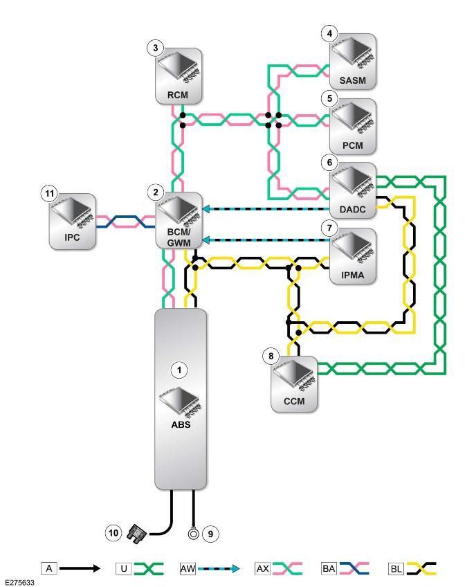
E275633

A = Hardwired: U = Private CAN: AW = BroadR-Reach®: AX = FlexRay: BA = HS CAN HMI Systems Bus: BL = HS CAN Underbody systems Bus.

ItemDescription
1ABS
2BCM/GWM
3RCM
4SASM
5PCM
6DADC
7IPMA
8CCM
9Ground
10Power supply
11IPC


Trailer Stability Assist (G2749280)

DESCRIPTION AND OPERATION

COMPONENT LOCATION

Component Location - 1 Of 1

NOTE:

The Right Hand Drive (RHD) vehicle is shown. The Left Hand Drive (LHD) vehicle is similar.
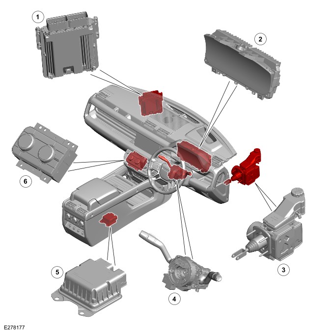
E278177

ItemDescription
1Powertrain Control Module (PCM)
2
3Integrated Power Brake
4>span class="acronym">Steering Angle Sensor Module (SASM)
5Restraints Control Module (RCM)
6Front Controls Interface Module (FCIM)

OVERVIEW

The trailer stability assist is designed to assist the driver by automatically detecting and correcting. The system detects the trailer is starting to oscillate when being towed at speed and takes specific corrective actions to eliminate trailer sway. The system corrects any dangerous trailer sway through a combination of torque reduction and individual wheel braking to bring the tow-vehicle and trailer back under control. The system also automatically warns the driver in the vehicle behind by flashing the turning light on both the car and the trailer.

The braking control is applied by the Integrated Power Brake system. The torque reduction is controlled by the PCM.

DESCRIPTION

Integrated Power Brake

NOTE:

The RHD vehicle is shown. The LHD vehicle is similar.
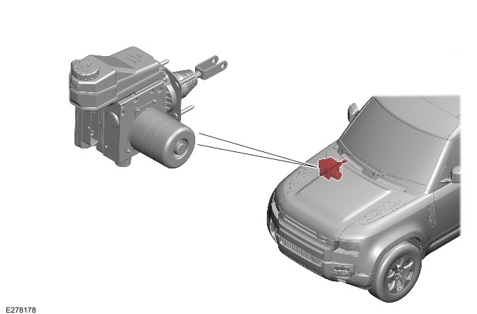
E278178

The Integrated Power Brake is located on the driver side of the engine compartment. The Integrated Power Brake is an electro-hydraulic unit that provides power assistance without needing a vacuum supply.

The Integrated Power Brake processes the information received from the sensors according to control algorithms integrated into the Integrated Power Brake control module. The result of these calculations form a control signal that is sent to the Hydraulic Control Unit (HCU). The HCU increases and decreases the pressure in the brakes of the vehicle according to the functional requirement.

For additional information, refer to: Integrated Power Brake System (206-08 Brake Controls and Actuation, Description and Operation).

Restraints Control Module

NOTE:

The RHD vehicle is shown. The LHD vehicle is similar.
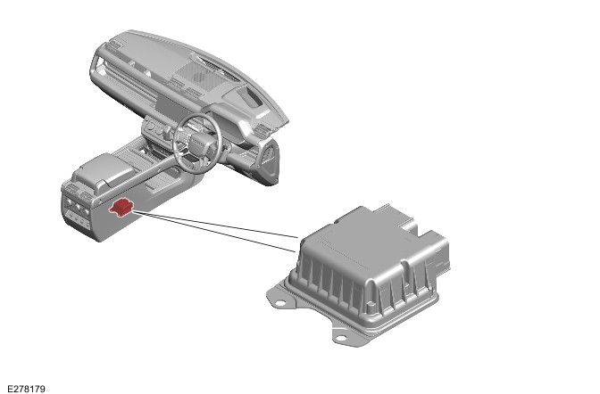
E278179

The RCM is located under the floor console.

The functions of the yaw sensor and lateral acceleration sensor for dynamic stability control are integrated into the RCM. The RCM provides data to the Integrated Power Brake control module through the FlexRay.

The signals of the yaw rate sensor and the lateral acceleration sensor are used to calculate the actual trajectory of the vehicle. If the intended direction and the actual motion of the vehicle are difference, the Integrated Power Brake system attempts to correct the vehicle motion by applying the brakes selectively.

For additional information, refer to: Integrated Power Brake System (206-08 Brake Controls and Actuation, Description and Operation).

Powertrain Control Module

NOTE:

The RHD vehicle is shown. The LHD vehicle is similar.
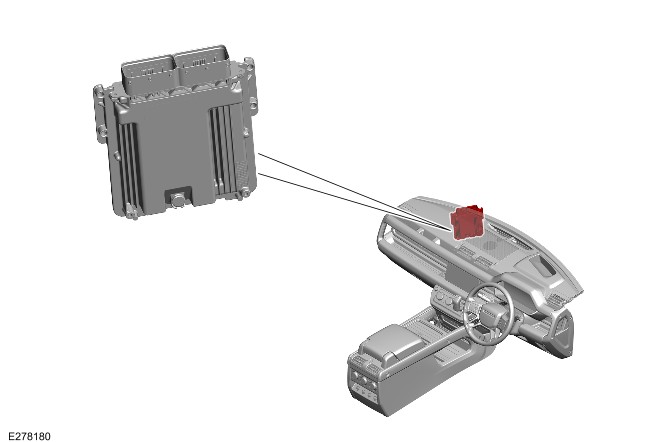
E278180

The PCM is located behind the secondary bulkhead panel in the centerline of the vehicle. The PCM receives inputs from various sensors and outputs reference voltages and signal information to other sensors for engine control.

The PCM receives a vehicle speed signal on the Flexray. The vehicle speed comes from the Integrated Power Brake control module. The vehicle speed is an important input to the PCM strategies. The Integrated Power Brake control module derives the speed signal from the wheel speed sensors.

Steering Angle Sensor Module

NOTE:

The RHD vehicle is shown. The LHD vehicle is similar.
E278181

The SASM is integrated into the Steering Wheel Module (SWM). The SASM is able to measure steering wheel angle and steering wheel rotation speed.

The SASM sends the measured signals to other vehicle systems through the FlexRay.

Tow Bar Control Module

NOTE:

Vehicle with 5 doors is shown. Vehicle with 3 doors is similar.
E278182

The Tow Bar Control Module (TBM) is under the loadspace floor.

The TBM is connected to the 13-pin trailer socket. The TBM sends the signals (a trailer attached to the vehicle) to other vehicle systems through the High Speed (HS) Controller Area Network (CAN) body systems bus.

Instrument Panel Cluster Control Module

NOTE:

The RHD vehicle is shown. The LHD vehicle is similar.

E274523

The IPC is located in the instrument panel on the driver side. The IPC communicates with other vehicle systems through the HS CAN Human Machine Interface (HMI) systems bus.

The IPC informs the state of the trailer stability assist to the user through an icon and a message on the message center.

For additional information, refer to: Instrument Panel Cluster (413-01 Instrument Cluster, Description and Operation).

Icon - Dynamic Stability Control
E269764

The Dynamic Stability Control (DSC) soft key is on the screen of the Interactive Display Module 'A' (IDMA).

The DSC system automatically enables in Power Mode 6 (ignition ON). When the DSC system is intervenes, the amber DSC warning indicator flashes.

OPERATION

When the 13-pin trailer socket is connected to a trailer, the TBM sends a signal to the Body Control Module (BCM)/Gateway Module A (GWM). The signal (a trailer is connected) is passed on the HS CAN body systems bus. The BCM/GWM sends a signal to the Integrated Power Brake control module on the FlexRay that a trailer is connected. The Integrated Power Brake control module implements the additional TSA operating strategy.

When the 13-pin trailer socket is connected, the trailer stability assist implements an algorithm to detect the characteristics of trailer sway.

The system detects sway movement caused by trailer oscillations at vehicle speeds of 50 km/h (31 mph) to 160 km/h (99 mph) and acts to eliminate them. Braking the vehicle asymmetrically counterbalances the sway movement, thereby slowing the vehicle and eliminating the oscillations. The Engine Management System (EMS) reduces the engine torque output to support the braking management in stabilizing the vehicle and trailer.

Trailer sway can occur when:

  • Changing highway lanes
  • Traversing a lengthy bend
  • Accelerating
  • Braking
  • Towing an overweight or incorrectly laden trailer.

The main benefit of the trailer stability assist is to respond early at the beginning of trailer sway. The trailer stability assist is almost unnoticeable under normal driving conditions and keeps the vehicle and trailer under safe control. The trailer stability assist requires no input from the driver and operates from 50 km/h (30 mph) to 160 km/h (99 mph).

Diagnostics

The Integrated Power Brake control module records any Diagnostic Trouble Code(s) (DTC) and related data. Read the DTC and related data with the Jaguar Land Rover (JLR) approved diagnostic equipment.

The JLR approved diagnostic equipment enables certain components to be activated and also live data to be read.

CONTROL DIAGRAM

Control Diagram - 1 Of 1
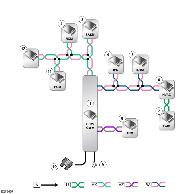
E278457

A = Hardwired: U = Private CAN bus: AX = FlexRay: AZ = HS CAN body systems bus: BA = HS CAN HMI systems bus.

ItemDescription
1BCM/GWM
2RCM
3SASM
4IPC
5IDMA
6HVAC Control Module (HVAC)
7FCIM
8TBM
9Ground
10Power supply
11PCM
12Integrated Power Brake control module


Instrument Cluster (G2323747)

SPECIFICATIONS

Torque Specifications

Component Torque Location
E253492
 DescriptionNmlb-ftlb-in
1Instrument panel left upper tray bracket screw1.7-15
2Steering column lower trim panel screw1.7-15
Component Torque Location
E253493
 DescriptionNmlb-ftlb-in
3Instrument panel center upper tray bracket screw1.7-15
Component Torque Location
E253494
 DescriptionNmlb-ftlb-in
4Steering column upper trim panel screw1.7-15
Component Torque Location
E253495
 DescriptionNmlb-ftlb-in
5Instrument Cluster (IC) lens screw2-18
6IC screw1.7-15

Instrument Panel Cluster (G2432057)

DESCRIPTION AND OPERATION

COMPONENT LOCATION

Component Location - 1 Of 1

NOTE:

right hand drive (RHD) vehicle is shown, left hand drive (LHD) vehicle is similar.
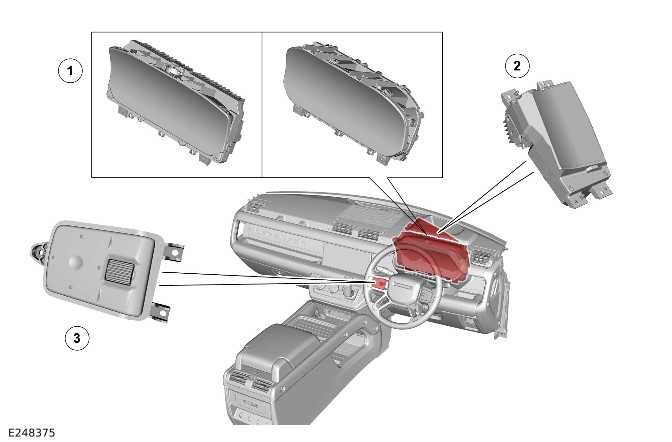
E248375

ItemDescription
1
2>span class="acronym">Head Up Display (HUD) (if equipped)
3Left steering wheel switch

OVERVIEW

Instrument Panel Cluster - Conventional Display

The IPC conventional display comprises of 2 analog gauges for the speedometer and tachometer. A 7 inch message center provides driver information.

The speedometer is located on the left and the tachometer is located on the right of the IPC.

The speedometer is available in 2 market variants:

  • Major scale miles per hour (mph)
  • Major scale kilometers per hour (km/h).

The tachometer has 2 variants:

  • Maximum of 7,000 >span class="acronym">Revolutions Per Minute (RPM) for petrol variants
  • Maximum of 5,000 RPM for diesel variants.

The IPC has 4 market variants.

Instrument Panel Cluster - Virtual Display

The IPC is a 12.3 inch High Definition (HD) TFT display.

The IPC is designed to look similar to a conventional IPC for the main display. The display can be continually reconfigured to prioritize and refine the information presented to the driver. All displays are virtual gauges with the speedometer and the tachometer being the dominant features of the display.

Head Up Display (If Equipped)

The HUD is a transparent display that presents data without the driver requiring to look away from their viewpoint.

A virtual image is displayed on the windshield which appears at a distance of approximately 2 meters. This gives the impression that the image appears around the end of the hood.

This function is designed to provide an increase in safety and convenience by concentrating on the road condition.

The HUD is designed to work with a specially designed windshield, which is formed to prevent double images and achieve the best display performance.

DESCRIPTION

Instrument Panel Cluster - Conventional Display
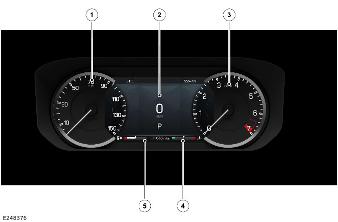
E248376

ItemDescription
1Speedometer
2Message center
3Tachometer
4Engine coolant temperature gauge
5Fuel gauge

The IPC is located in the instrument panel. The IPC comprises 2 analog gauges, the speedometer and tachometer. Between the analog gauges, a 7 inch TFT display is provided for driver information.

The analog speedometer and tachometer are located in the IPC. The speedometer and tachometer are each driven by an electronic stepper motor. The characteristics of this type of motor produce damping of the pointer needle. Both of the gauges return to their respective zero positions when the ignition is switched OFF.

Instrument Panel Cluster - Virtual Display
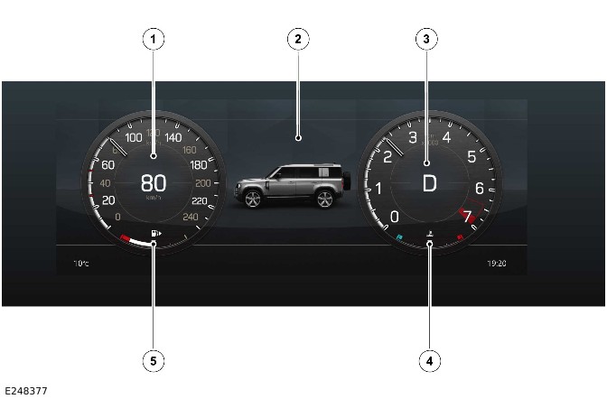
E248377

ItemDescription
1Speedometer
2Message center
3Tachometer
4Engine coolant temperature gauge
5Fuel gauge

The IPC comprises a 12.3 inch HD TFT with a multilayered virtual display. The IPC has a high level of graphic presentation and interactive functionality. These features give the driver advanced levels of control and set-up using interactive graphic menu features.

The IPC combines a virtual representation of virtual analog instruments, graphic information, digital information and warning signals.

The virtual instrument panel can be configured using the steering wheel controls to meet personal preference.

The following options are available:

  • 2 dial - Display the speedometer and power gauge either side of the information panel.
  • 1 dial - Display 2 information panels either side of a central power gauge.
  • Full map - Display the navigation system information over the entire instrument panel.
  • Media - Display the current media source information over the entire instrument panel.
  • Driver assistance - Display the current enabled driver assistance features over the entire instrument panel.

Additional Instrument Cluster Features - Only Virtual Display

NOTE:

RHD vehicle is shown, LHD vehicle is similar.
E248378

ItemDescription
1Speaker - IPC

A speaker is installed on the top of the IPC casing. The speaker chimes audible warnings and is controlled by a generator within the IPC. The speaker cannot be replaced separately.

The IPC is integrated into the vehicle start authorization process as it includes encoded data exchange information as part of the distributed start authorization strategy.

Instrument Panel Cluster - General Information

The driver can set up a number of features and find out essential information about the vehicle in the IPC display menu which consists of the following sections:

  • Phone - Contains a list of recent phone contacts, when a smartphone is paired and contacted.
  • Media - Displays information on the current media source
  • Trip - Displays trip meter information and settings.
  • Info panel (conventional display) - Contains sub-menus and settings to allow the driver to configure the instrument panel's display.
  • Display (virtual display) - Contains sub-menus and settings to allow the driver to configure the instrument panel's display.
  • HUD (if equipped) - HUD sub-meuns and settings.
  • Vehicle - Contains sub-menus and settings for the Tire Pressure Monitoring System (TPMS) and passenger airbag.

The IPC menu can be accessed by using the left steering wheel switch located on the left side of the steering wheel.

The message center displays vehicle related information to the driver. The fuel gauge and temperature gauge are located in the message center.

The low fuel warning indicator is located next to the fuel gauge, the engine temperature warning indicator is located next to the temperature gauge.

Warning indicators and the gear position status are also displayed in the message center.

Driver information is also displayed, for example:

  • Navigation turn-by-turn information
  • Trip computer information
  • Off-road information
  • Driver Assistance information
  • Basic audio details.

For additional information, refer to: Message Center (413-08 Message Center, Description and Operation).

IPC illumination - Ambient light sensors
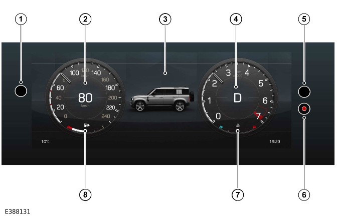
E388131

ItemDescription
1Ambient light sensor - Left
2Speedometer
3Message center
4Tachometer
5Ambient light sensor - Right
6Security Light Emitting Diode (LED)
7Engine coolant temperature gauge
8Fuel gauge

The IPC illumination has both day and night illumination modes. These are determined by the IPC ambient lighting control strategy.

NOTE:

The vehicle must be in power mode 7 (engine on).

Daytime illumination will offer a higher IPC light output so that the display can be seen in a high ambient light environment without offering a large light contrast between the interior and exterior of the vehicle.

Night illumination will offer a lower IPC light output so that the display can be seen in a low ambient light environment without offering a large light contrast between the interior and exterior of the vehicle.

Two ambient light sensors are positioned at either side of the IPC. See figure E388131.

Both the left and right ambient light sensors must receive the same light input to initiate a change in illumination intensity.

For example, when testing the system in high ambient light conditions, both sensors must be covered to initiate night illumination mode.

Depending on hardware and software levels, it can take between 15 seconds and 2 minutes 30 seconds for the IPC illumination to change.

Warning Indicators
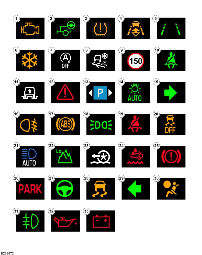
E263872

ItemDescription
1Malfunction Indicator Lamp (MIL) warning indicator (amber)
2Trailer turn signal warning indicator (green)
3Tire Pressure Monitoring System Control Module (TPM) warning indicator (amber)
4Follow mode warning indicator (amber)
5Lane departure warning (green)
6External temperature warning (amber)
7Auto stop/start warning indicator
8Grass gravel snow
9Traffic sign speed
10Seatbelt warning indicator (green)
11Access mode indicator
12Critical warning indicator (red)
13Valid parking spaces on both sides
14Auto light
15Turn signal indicator active (green)
16Rear fog lamps active warning indicator (amber)
17Anti-Lock Brake System Control Module (ABS) warning indicator (amber)
18Side lamps active warning indicator (green)
19Seatbelt warning indicator (red)
20Dynamic Stability Control (DSC) OFF warning indicator (amber)
21Auto High Beam (AHB) active warning indicator (blue)
22Range change selection
23Low traction launch
24Diesel Exhaust Fluid (DEF) (red)
25Brake system warning indicator (red)
26Electric Park Brake (EPB) system warning indicator (red)
27Steering assist active (green)
28DSC active warning indicator (amber)
29Turn signal indicator active (green)
30Airbag warning indicator (amber)
31Front fog lamps active warning indicator (green)
32Oil pressure warning indicator (red)
33Charge warning indicator (red)

The IPC features a number of warning indicators. The warning indicators are located in various positions in the IPC. The warning indicators illuminate in 1 of 5 colors which indicate at the level of importance of the warning as follows:

  • Red = Warning
  • Yellow = Caution
  • Green = System operative
  • Blue = Headlamp high beam operative
  • White = Information.

The warning indicators are mainly located in 3 groups:

  • In the speedometer display
  • In the tachometer display
  • In a central position at the top of the message center.

The IPC illuminates the warning indicators through signals from other system control modules and sensors. These signals are received by the IPC on the High Speed (HS) Controller Area Network (CAN) Human Machine Interface (HMI) systems bus. Some indicators are activated by an external system control module but the IPC contains the control logic.

Head Up Display (If Equipped)

NOTE:

RHD vehicle is shown, LHD vehicle is similar.
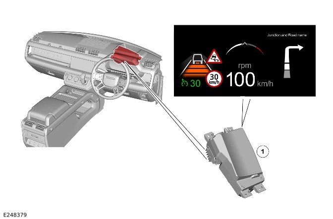
E248379

ItemDescription
1HUD

The HUD is located inside the instrument panel behind the IPC.

The HUD features a full color TFT display which is video capable. This option requires the IPC virtual display installed.

Head Up Display - Zone Layout

NOTE:

Not all the information below will be displayed at the same time, zone displays will be shown based on prioritization and/or boundary overlap.
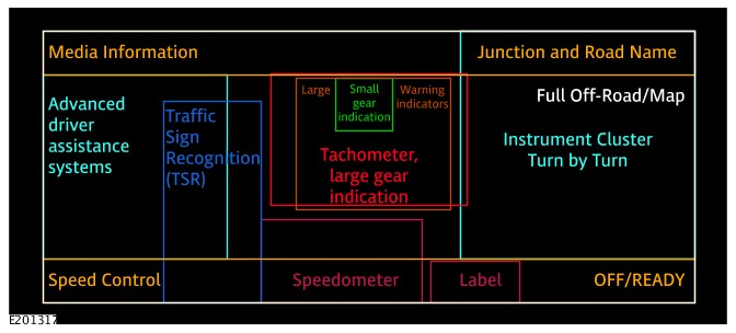
E201317

The following zones can be displayed in the HUD:

  • Speedometer zone - Vehicle speed value
  • Label zone - Speed units
  • Large warnings zone - Forward alert, driver intervene
  • Advanced driver assistance systems zone:
    • Lane Departure Warning (LDW)/Lane Keep Assist (LKA) tracking
    • LDW/LKA alert
    • LDW/LKA idle/OFF
    • Adaptive speed control gap setting and follow mode
    • Steering control
    • Side swipe (side obstacle detection system function)
    • Traffic jam assist/integrated cruise assist.
  • Set speed info zone - Speed control and auto speed limiter.
  • Junction and road name zone - Navigation next road name.
  • Turn by turn zone - Navigation display, navigation video display.
  • The Traffic Sign Recognition (TSR) and the TSR zone - Warning signs, vehicle speed units/value, overtake, speed text and sign type.
  • Small gear display zone - gear state.
  • Tachometer and large gear display zone - Large gear position, gear upshift indicator.
  • Full off road/map zone - Full screen 4x4i.

When selected the HUD feature projects the following driver information display onto the inside of the windshield:
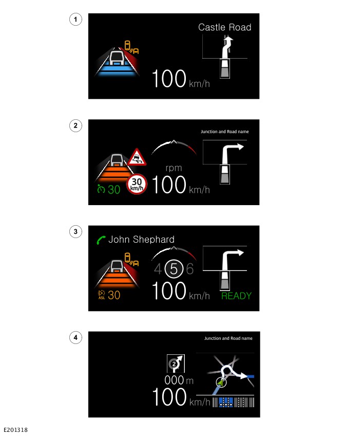
HUD - Display Themes
E201318

ItemDescription
1LDW/vehicle speed/navigation next road name
2Auto speed limiter, TSR/vehicle speed and navigation
3Speed limiter/ vehicle speed/ gear position
4Junction and road name zone

OPERATION

Instrument Panel Cluster

The IPC receives a permanent power supply from the startup battery through the Passenger Junction Box (PJB). A hardwired LED security system status indicator is connected to the IPC from the Body Control Module (BCM)/Gateway Control Module (GWM).

The speedometer is driven by square wave signals derived from the wheel speed sensors which is hardwired to the ABS. The ABS transmits the signal to the BCM/GWM through the HS CAN Underbody (UN) systems bus. The IPC receives the signal form the BCM/GWM through the HS CAN HMI systems bus.

The tachometer is driven by an engine speed signal from the Crankshaft Position Sensor (CKP) which is hardwired to the Powertrain Control Module (PCM). The PCM transmits the signal from the CKP sensor to the BCM/GWM through the FlexRay. The IPC receives the signal from the BCM/GWM through HS CAN HMI systems bus.

The Electric Steering Column Lock Control Module (VIM) is connected directly to the IPC on a hardwired connection. The IPC provides a controlled ground for the VIM. The Steering Wheel Switch inputs are sent to the IPC through the Local Interconnect Network (LIN) connection.

For additional information, refer to: Steering Column and Steering Wheel (211-04 Steering Column and Steering Wheel, Description and Operation).

The Front Infotainment Control Module (IGM / ICCM) and the HUD are connected to the IPC by:

  • Automotive Pixel Link 2 (APIX2) connection
  • HS CAN HMI systems bus.

Other vehicle sensors are connected to the BCM/GWM which processes the signals from the sensors. The processed signals are delivered to the IPC on the HS CAN HMI systems bus. The IPC communicates with the vehicle infotainment system on the HS CAN HMI systems bus.

Head Up Display

The HUD receives a permanent battery voltage supply through the PJB. A HS CAN HMI systems bus connection allows the HUD to communicate with other modules. The IPC virtual display is also connected to the HUD through APIX2.

The HUD is controlled from the message center menu.

When selected, the menu offers the following options:

  • Selecting the position of the display on the windshield.
  • Selecting the brightness of the display.
  • Selecting which information is displayed on the HUD.

Control of the display brightness can be adjusted in 3 different ways:

  • As listed above, manually, from within the HUD selection of the 'Main Menu' in the message center.
  • When the vehicle lighting is switched on, the HUD display adjusts simultaneously with the manual adjustment of the IPC dimmer.
  • Automatic brightness, controlled using data from the rain/light sensor.

The HUD showroom mode is controlled from the IPC service menu and displays example images on the windshield when the vehicle is stationary.

Prior to selecting the HUD windshield position the user must select their desired seating position. The steering wheel controls are used to set the horizontal position of the windshield display. When set, the information can be saved in the seat memory control system, storing the selected preferences.

Left Steering Wheel Switch

The left steering wheel switch has LIN connection to the:

  • IPC
  • IGM / ICCM.

The left steering wheel switch and the right steering wheel switch contain capacitive sensors and microcontrollers.

The switch assembly contains a control module. The steering wheel switch microcontroller reads the capacitive sensor to detect the selected switch function. The function confirmation is through a central microswitch.

The control module converts this information into a LIN message which is passed through the Steering Wheel Module (SWM) to the IPC.

Diagnostics

The IPC records any Diagnostic Trouble Codes (DTC) and related data. The DTC and related data are read using the Jaguar Land Rover (JLR) approved diagnostic equipment.

The JLR approved diagnostic equipment enables certain components to be activated and also read live data.

CONTROL DIAGRAM

Control Diagram - 1 of 2 - Instrument Panel Cluster
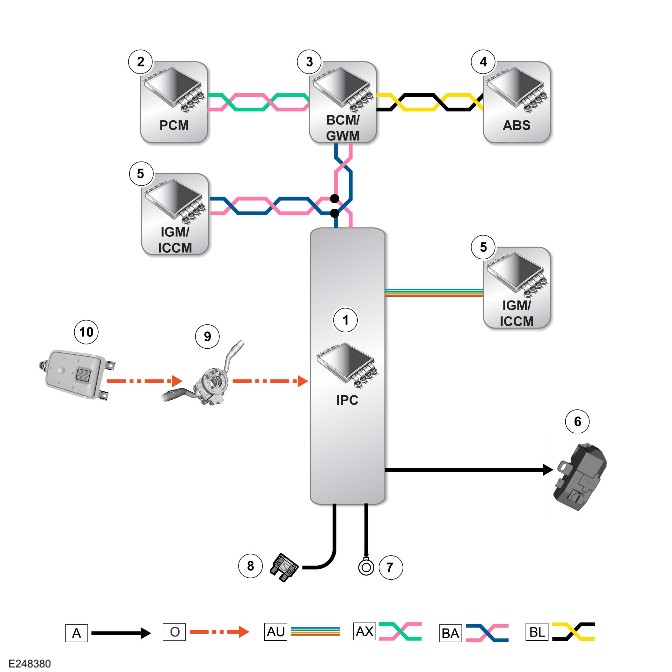
E248380

A = Hardwired: O = LIN: AU = APIX2: AX = FlexRay: BA = HS CAN HMI Systems Bus: BL = HS CAN UN Systems Bus.

ItemDescription
1IPC
2PCM
3BCM/GWM
4ABS
5IGM / ICCM
6VIM
7Ground
8Power supply
9SWM
10Left steering wheel switch

Control Diagram - 2 Of 2 - Head Up Display
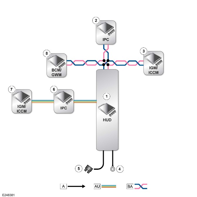
E248381

A = Hardwired: AU = APIX2: BA = HS CAN HMI Systems Bus.

ItemDescription
1HUD
2IPC
3IGM / ICCM
4Ground
5Power supply
6IPC
7IGM / ICCM
8BCM/GWM


Instrument Cluster (G2323748)

REMOVAL AND INSTALLATION

  • 88.30.38
  • Instrument Cluster - Renew
  • All Derivatives
  • 1.00
  • USED WITHINS

General Equipment

Equipment name
Land Rover diagnostic equipment

Removal

NOTES:

  • When a new instrument cluster is to be installed, the Jaguar Land Rover (JLR) approved diagnostic system must be connected to the vehicle and the instrument cluster renewal procedure followed. This will allow vehicle coding data and current service interval data to be correctly installed to the new instrument cluster.
  • For non-NAS markets - If a new instrument cluster is to be installed, a new Remote Function Actuator (RFA) will be required. All vehicle keys must be presented to complete the RFA renewal.
  • This procedure contains some variation in the illustrations depending on the vehicle specification, but the essential information is always correct.
  • This procedure contains illustrations showing certain components removed to provide extra clarity.
  1. CAUTION:

    If the software number is K8D2-14C104-AC or L8B2-14C104-AC, a new RFA will be required.

    NOTE:

    Non-NAS Markets only.

    Using the Land Rover diagnostic equipment, read the RFA software number.General Equipment: Land Rover diagnostic equipment
  2. E251841 Position the steering wheel as illustrated.
  3. Disconnect the startup battery ground cable.Refer to: 12V System Disconnect and Connect (414-00 Battery and Charging System - General Information, General Procedures).
  4. Remove the instrument panel lower trim.Refer to: Instrument Panel Lower Trim (501-12 Instrument Panel and Console, Removal and Installation).
  5. E251836 Remove the instrument panel left upper tray at the 2 fasteners.
  6. E251837
    • Remove the 2 screws and 1 bolt.
    • Remove the bracket of the instrument panel left upper tray.
  7. E251838 Remove the instrument panel center upper tray at the 2 fasteners.
  8. CAUTION:

    Take extra care not to damage the component.

    E251742
    • Remove the 2 screws.
    • Release the trim panel at the 2 clips.
  9. E251743
    • Disconnect the 2 electrical connectors from the 2 switches.
    • Remove the trim panel.
  10. E251839
    • Remove the 3 screws.
    • Disconnect the electrical connector from the in-vehicle temperature sensor.
    • Remove the bracket of the instrument panel center upper tray.
  11. CAUTIONS:
    • Do not use metal tools during this operation, removal of the component(s) must be completed with a plastic trim tool.
    • Take extra care not to damage the component.
    E251842
    • Use a suitable plastic trim tool, release the 6 clips.
    • Disconnect the electrical connector from the ambience lighting wiring harness.
    • Remove the instrument cluster upper trim panel.
  12. E251843
    • Release the 8 clips.
    • Remove the 4 screws.
    • Remove the steering column upper trim panel.
  13. CAUTION:

    Take extra care not to damage the component.

    E251844
    • Remove the 4 screws.
    • Remove and discard the 2 fasteners.
    • Release the instrument cluster.
  14. E251845
    • Disconnect the 3 electrical connectors from the instrument cluster.
    • Remove the instrument cluster.

Installation

  1. CAUTION:

    Take extra care not to damage the component.

    • Connect the 3 electrical connectors to the instrument cluster.
    • Install the instrument cluster.
    • Install the 2 new fasteners.
    • Install and tighten the 4 screws.Torque: 1.7Nm
    • Install the steering column upper trim panel.
    • Secure the 8 clips.
    • Install and tighten the 4 screws.Torque: 1.7Nm
  2. CAUTIONS:
    • Make sure the connector is correctly secured.
    • Take extra care not to damage the component.
    • Connect the electrical connector to the ambience lighting wiring harness.
    • Install the instrument cluster upper trim panel to the 6 clips.
    • Install the bracket of the instrument panel center upper tray.
    • Install and tighten the 3 screws.Torque: 1.7Nm
    • Connect the electrical connector in-vehicle temperature sensor.
  3. Install the instrument panel center upper tray to the 2 fasteners.
    • Connect the 2 electrical connectors to the 2 switches.
    • Install the trim panel at the 2 clips.
    • Install and tighten the 2 screws.Torque: 0.6Nm
    • Install the bracket of the instrument panel left upper tray.
    • Install and tighten the 2 screws and 1 bolt.Torque: 1.7Nm
  4. Install the instrument panel left upper tray to the 2 fasteners.
  5. Install the instrument panel lower trim.Refer to: Instrument Panel Lower Trim (501-12 Instrument Panel and Console, Removal and Installation).
  6. CAUTION:

    Only applicable vehicles with software numbers K8D2-14C104-AC or L8B2-14C104-AC as detailed in removal step 1.

    NOTES:
    • Only complete this step if a new instrument cluster is to be installed.
    • Non-NAS Markets only.
    • SRO must be claimed separately.
    • All keys need to be present for the RFA replacement.
    Install a new RFA.Refer to: Remote Function Actuator (419-10 Multifunction Electronic Modules, Removal and Installation).
  7. Connect the startup battery ground cable.Refer to: 12V System Disconnect and Connect (414-00 Battery and Charging System - General Information, General Procedures).


Warning Devices (G2342531)

DESCRIPTION AND OPERATION

COMPONENT LOCATION

Component Location - 1 of 6 - Blind spot assist

NOTES:

  • Vehicle with 5 doors is shown, vehicle with 3 doors is similar.
  • Right hand drive vehicle is shown, left hand drive vehicle is similar.
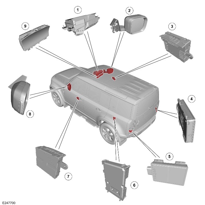
E247700

ItemDescription
1Head Up Display (HUD)
2Approaching vehicle lamp - Right door mirror
3Driver Door Control Module (DDM)
4Side Obstacle Detection Control Module - Right (SODR)
5Side Obstacle Detection Control Module - Left (SODL)
6Audio Amplifier Control Module (AAM)
7Passenger Door Control Module (PDM)
8Approaching vehicle lamp - Left door mirror
9Instrument Panel Cluster (IPC)

Component Location - 2 of 6 - Reverse Traffic Detection

NOTES:

  • Vehicle with 5 doors is shown, vehicle with 3 doors is similar.
  • Right hand drive vehicle is shown, left hand drive vehicle is similar.
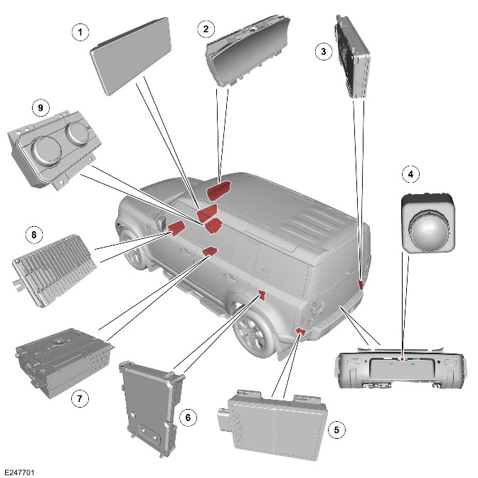
E247701

ItemDescription
1Touchscreen
2IPC
3SODR
4Rear view camera
5SODL
6AAM
7Front Infotainment Control Module (IGM / ICCM)
8Near Field Sensing Module (NFSM)
9Integrated Control Panel (FCIM)

Component Location - 3 of 6 - Lane Keep Assist

NOTES:

  • Vehicle with 5 doors is shown, vehicle with 3 doors is similar.
  • Right hand drive vehicle is shown, left hand drive vehicle is similar.
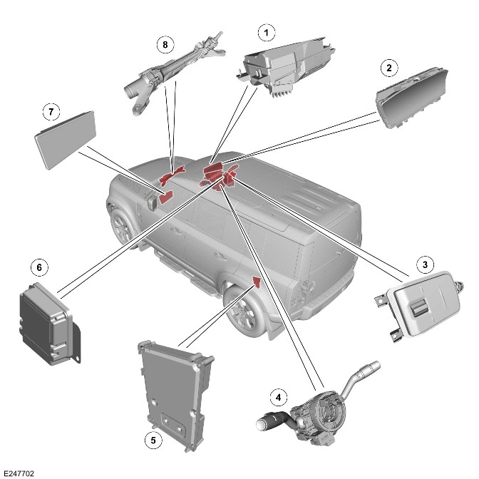
E247702

ItemDescription
1HUD
2IPC
3Steering wheel switch - Right
4Steering Wheel Module (SWM)
5AAM
6Driver Assistance Domain Controller (DADC)
7Touchscreen
8Power Steering Control Module (PSCM)

Component Location - 4 of 6 - Traffic Sign Recognition

NOTES:

  • Vehicle with 5 doors is shown, vehicle with 3 doors is similar.
  • Right hand drive vehicle is shown, left hand drive vehicle is similar.
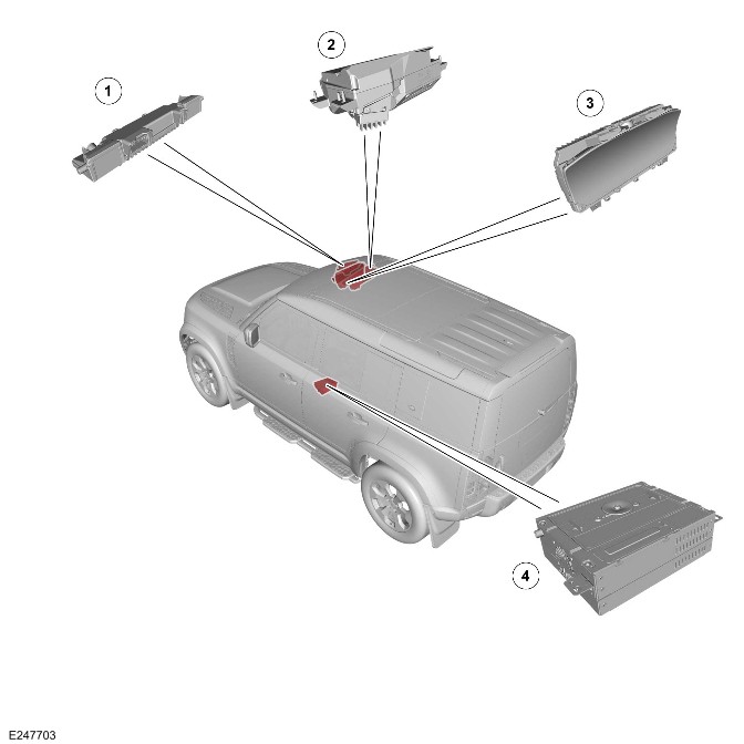
E247703

ItemDescription
1Image Processing Module 'A' (IPMA)
2HUD
3IPC
4IGM / ICCM

Component Location - 5 of 6 - Clear Exit Detection System

NOTES:

  • Vehicle with 5 doors is shown, vehicle with 3 doors is similar.
  • Right hand drive vehicle is shown, left hand drive vehicle is similar.
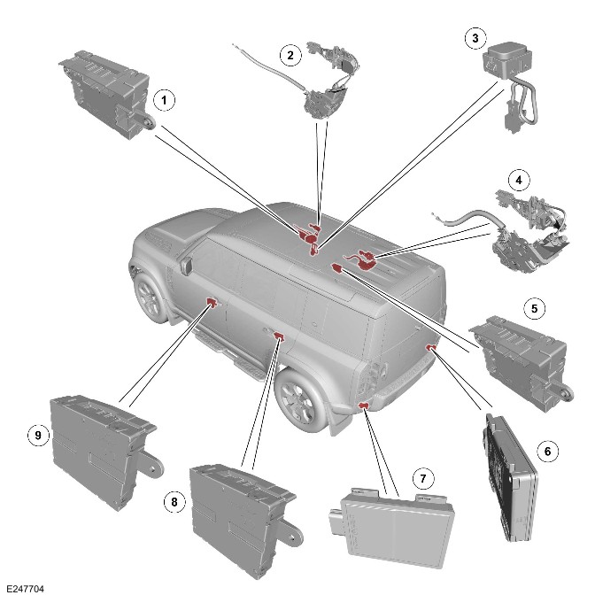
E247704

ItemDescription
1DDM
2Front door ajar switch (quantity 2)
3Clear Exit Detection System (CEDS) Light Emitting Diode (LED) indicator (quantity 4) (If equipped)
4Rear door ajar switch (quantity 2) (If equipped)
5Driver Rear Door Module (DRDM)
6SODR
7SODL
8Passenger Rear Door Module (PRDM)
9PDM

Component Location - 6 of 6 - Driver Condition Monitor

NOTES:

  • Vehicle with 5 doors is shown, vehicle with 3 doors is similar.
  • Right hand drive vehicle is shown, left hand drive vehicle is similar.
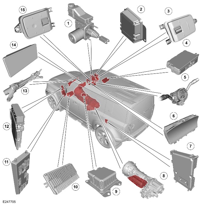
E247705

ItemDescription
1Integrated power brake
2DADC
3Steering wheel switch - Right
4Seat Module - Driver/Passenger/Rear - Left/Right (DSM)
5SWM
6IPC
7AAM
8Transmission Control Module (TCM)
9Restraints Control Module (RCM)
10NFSM
11Body Control Module (BCM)/Gateway Control Module (GWM)
12Powertrain Control Module (PCM)
13PSCM
14Touchscreen
15Steering wheel switch - Left

OVERVIEW

Blind Spot Assist

WARNING:

The blind spot assist system is a driver aid and not a safety device. The driver must always exercise due care and attention while driving.

The blind spot assist is an enhancement to the following features:

  • Blind Spot Monitoring (BSM)
    • To help the driver to safely crossover in moving traffic and default ON.
  • Approaching Vehicle Sensing (AVS).
    • To view a larger area to the rear of the vehicle. AVS warns the driver that a vehicle is approaching but is not in the blind spot area.

The blind spot assist is designed to help prevent a collision. If the system detects a vehicle and the driver attempts to change lane, a counter torque is applied to the steering. The system is designed to guide the vehicle away from the approaching vehicle.

Lane Keep Assist System

WARNING:

The Lane Keep Assist (LKA) system is designed as a driver aid not a safety device. The driver must always exercise due care and attention while driving.

The LKA helps the driver to keep the vehicle in the current road lane by applying a gentle steering wheel torque. The LKA only applies this torque when the vehicle unintentionally drifts out of the road lane.

The DADC and Electric Power Assisted Steering (EPAS) components determine the trajectory of the host vehicle to pull back parallel to the lane to avoid:

  • Crossing the lane.
  • Road edge.
  • An oncoming vehicle in the adjacent lane.

The Emergency Lane Keep Assist (ELKA) system is the sub system which belongs to LKA.

Reverse Traffic Detection

The Reverse Traffic Detection is split into 2 features:

  • Rear Traffic Warning
    • The feature detects cross traffic moving target objects from speeds of approximately 3.6 km/h (2.2 mph) up to 70 km/h (43 mph).
    • If activated, the touchscreen displays the collision impact alert icon on the relevant side(s) of the screen. The collision impact alert icon informs the driver the vehicle is about to reverse into the path of a moving object.
    • If a detected object is calculated to be a collision threat, it is displayed as red colored blocks.
    • An audible warning also sounds when collision threat is detected.
  • Rear Traffic Braking
    • In the event of an imminent collision, the feature applies the brakes to try and prevent an accident. All emergency braking warnings are displayed through the IPC.

Rear protection monitor

The rear protection monitor system helps identify any potential collision risks from the rear of the vehicle. The system:

  • Monitors an area of approximately 80 meters behind the vehicle for threats from other vehicles that are approaching the rear at high speeds.
  • Warns the driver of the vehicle approaching behind, of any potential collision by flashing the hazard warning lamp rapidly.
  • The default mode is ON and the driver cannot switch the system OFF.

Clear Exit Detection System

WARNING:

Clear exit monitor is a user aid only. The user is responsible for making sure that the door is opened with necessary care and attention. The user must make sure the door is opened in a manner which is safe for the vehicle, its occupants, and other road users. Failure to operate the doors in a safe manner could lead to serious injury or death.

Clear exit monitor warns of a possible threat when opening any door from the inside. Sensors in the rear bumper monitor nearby traffic and determine if opening a door could pose a threat.

Driver Condition Monitor

WARNING:

The feature default setting is ON, and always returns to the default setting after every ignition cycle.

The feature continuously evaluates driving technique for signs of fatigue. The feature determines fatigue in 2 levels:

  • Fatigued
  • Highly fatigued.

Traffic Sign Recognition System

NOTE:

A reduced speed limit is also displayed if an approved Jaguar Land Rover (JLR) trailer socket is connected to the vehicle.

The traffic sign recognition system uses a forward facing camera located above the rear view mirror and the vehicle navigation map data.

The camera detects:

  • Speed signs
  • No over-taking signs
  • Variable overhead speed signs

SPEED LIMITER

NOTE:

Speed limiters are not available when cruise control or adaptive cruise control is in operation. When the vehicle is first switched ON, the vehicle reverts to whichever system was used previously.

The speed limiter allows the driver to manually restrict the maximum vehicle speed. When a maximum speed limit is set, the vehicle responds normally until the set speed is approached. At this point, the vehicle stops accelerating.

The adaptive speed limiter works in conjunction with the traffic sign recognition system and the navigation system to restrict the maximum vehicle speed. If the system cannot determine a valid maximum speed, the last known set speed limit is used.

CRUISE CONTROL

NOTE:

  • Do not use cruise control when driving off-road.
  • The cruise control cancels if the accelerator pedal is pressed to override the system for more than 1 minute.

Cruise control allows the vehicle to automatically maintain a set vehicle speed. The cruise control switch installed on the steering wheel is used to operate the system. The driver can also intervene, at any time, by using the brake or accelerator pedals.

ADAPTIVE CRUISE CONTROL OVERVIEW

NOTE:

  • The adaptive cruise control system illuminates the brake lights when it applies the brakes. A noise may also be heard.
  • The adaptive cruise control is not available when the speed limiter is in operation. When the vehicle is first switched ON, the vehicle reverts to whichever system was used previously.

The adaptive cruise control allows the driver to set a cruising speed for the vehicle. The vehicle speed is automatically reduced if a slower moving vehicle is detected in the lane ahead. The system then maintains a constant gap to the vehicle ahead. If the system detects that the slower moving vehicle is no longer present, it automatically raises the vehicle speed back to the set speed. In some scenarios, adaptive cruise control also brings the vehicle to a standstill, if required.

AUTONOMOUS EMERGENCY BRAKING

WARNING:

If Autonomous Emergency Braking (AEB) brings the vehicle to a stop, the brakes continue to hold the vehicle stationary for a few seconds. After this period, the driver must resume full control of the vehicle. Failure to take back full control of the vehicle could result in an accident, leading to serious injury or death.

NOTE:

Not all vehicles are equipped with AEB.

The AEB uses the forward facing camera located above the rear view mirror and forward facing radar, located behind the front grille. The camera and radar are used to help identify an imminent risk of collision with:

  • Another vehicle traveling in front.
  • An oncoming vehicle from an adjacent lane while the host vehicle is turning left or right.
  • A crossing pedestrian.
  • A pedestrian moving in the same direction as the vehicle.
  • An oncoming pedestrian from the opposite direction while the host vehicle is turning left or right.
  • A crossing cyclist.
  • A cyclist traveling in the same direction as the vehicle.

For additional information, refer to: Speed Control (310-03 Speed Control - INGENIUM I4 2.0L Petrol/INGENIUM I4 2.0L Petrol - PHEV, Description and Operation).

For additional information, refer to: Speed Control (310-03 Speed Control - INGENIUM I6 3.0L Petrol, Description and Operation).

For additional information, refer to: Speed Control (310-03 Speed Control - INGENIUM I4 2.0L Diesel, Description and Operation).

DESCRIPTION

Side Obstacle Detection Control Module

NOTE:

Vehicle with 5 doors is shown, vehicle with 3 doors is similar.
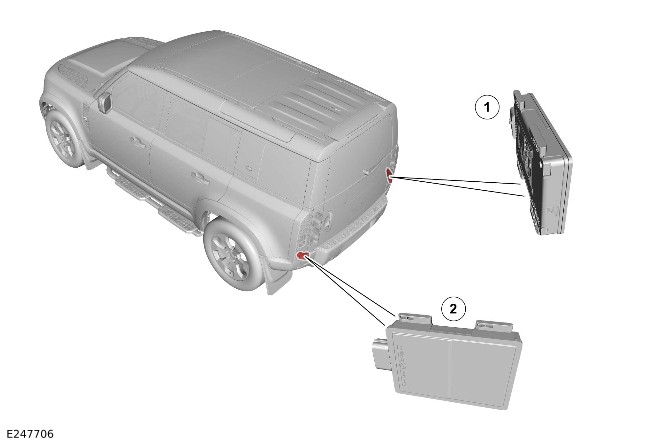
E247706

ItemDescription
1SODR
2SODL

There are 2 side obstacle detection control modules installed in the corner of the rear bumper, 1 on each side.

The SODR has the following connections:

  • Power
  • Ground
  • High Speed (HS) Controller Area Network (CAN) Underbody (UN) systems bus
  • Private CAN bus.

The SODL does not have a HS CAN UN systems bus connection.

The SODR and SODL exchange data on the private CAN bus. The SODR communicates the data on the HS CAN UN systems bus to the BCM/GWM.

The following systems are hosted in SODL/SODR:

  • BSM
    • The blind spot monitoring system monitors an area adjacent to the vehicle.
  • Reverse Traffic Detection
    • The rear traffic detection feature assists the driver when carrying out a reversing maneuver.
  • Rear protection monitor.
    • The rear protection monitor system helps identify any potential collision risks from the rear of the vehicle.

They are incorporated in each of the SODL/SODR and are connected by a Private CAN bus to exchange information.

Each SODL/SODR does an auto-alignment self-check every time when in use. The auto-alignment self-check can take up to an hour in some environments. However the BSM continues to operate as normal.

The SODR receives vehicle speed on the HS CAN UN systems bus.

Driver Assistance Domain Controller

NOTES:

  • Vehicle with 5 doors is shown, vehicle with 3 doors is similar.

    Right hand drive vehicle is shown, left hand drive vehicle is similar.

  • The DADC 'A' is not available on L663 20MY.
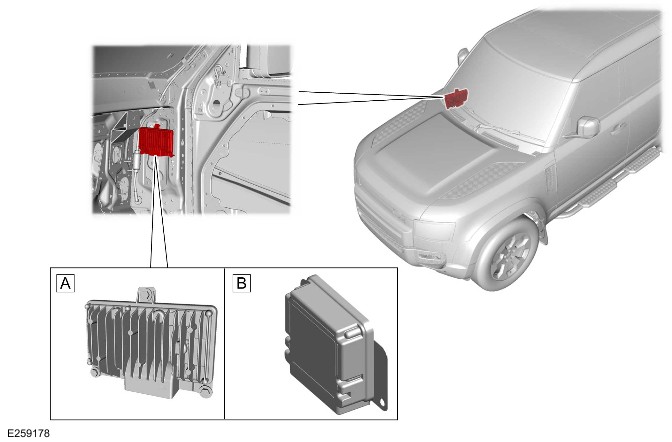
E259178

ItemDescription
ADADC 'A'
BDADC 'B'

The DADC is located behind the right of the instrument panel.

The following features are hosted in DADC:

  • LKA
  • Blind Spot Assist
  • Speed Limiter
  • Adaptive Speed Limiter
  • Cruise Control
  • Adaptive Cruise Control
  • Traffic Sign Recognition
  • Emergency Lane Keep Assist – Oncoming Vehicle
  • Emergency Lane Keep Assist Road Edge
  • Lane Change Collision Mitigation
  • City Urban - Automated Emergency Braking
  • Pedestrian – Automated Emergency Braking
  • Cyclist – Automated Emergency Braking
  • Rear Cross Traffic Alert
  • Rear Pre Crash.

For additional information, refer to: Speed Control (310-03 Speed Control - INGENIUM I4 2.0L Petrol/INGENIUM I4 2.0L Petrol - PHEV, Description and Operation).

For additional information, refer to: Speed Control (310-03 Speed Control - INGENIUM I6 3.0L Petrol, Description and Operation).

For additional information, refer to: Speed Control (310-03 Speed Control - INGENIUM I4 2.0L Diesel, Description and Operation).

IMAGE PROCESSING MODULE 'A'

NOTE:

Vehicle with 5 doors is shown, vehicle with 3 doors is similar.
E250787

The IPMA is located above the rear view mirror.

The IPMA has 1 forward facing camera. The IPMA receives an ignition supply from the Engine Junction Box (EJB). Information can be exchanged from the IPMA through an ETHERNET connection to the GWM which then re-directs the necessary signals to each ECU. The IPMA is also connected to the HS CAN UN system from which it receives necessary information to compute object detection correctly.

For additional information, refer to: Speed Control (310-03 Speed Control - INGENIUM I4 2.0L Petrol/INGENIUM I4 2.0L Petrol - PHEV, Description and Operation).

For additional information, refer to: Speed Control (310-03 Speed Control - INGENIUM I6 3.0L Petrol, Description and Operation).

For additional information, refer to: Speed Control (310-03 Speed Control - INGENIUM I4 2.0L Diesel, Description and Operation).

Near Field Sensing Module AND Near Field Sensing Module 'B'

NOTES:

  • Vehicle with 5 doors is shown, vehicle with 3 doors is similar.

    Right hand drive vehicle is shown, left hand drive vehicle is similar.

  • The NFSM 'B' is not available on L663 20MY.
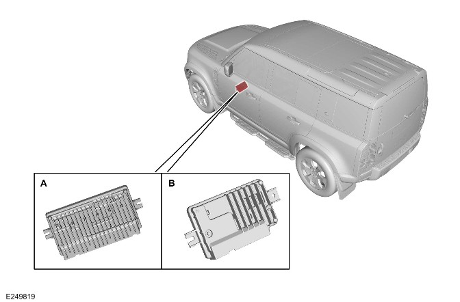
E249819

ItemDescription
ANFSM
BNFSM 'B'

The NFSM/NFSM 'B' is located below the instrument panel. The NFSM is equipped on vehicles with a proximity camera system, the NFSM 'B' is equipped on vehicles with a rear view camera system.

For additional information, refer to: Parking Aid (413-13 Parking Aid, Description and Operation).

Rear View Camera

NOTE:

Vehicle with 5 doors is shown, vehicle with 3 doors is similar.
E247713

The rear view camera is located in the center of the rear bumper, above the license plate.

For additional information, refer to: Parking Aid (413-13 Parking Aid, Description and Operation).

Clear Exit Detection System Indicator

NOTE:

Right hand drive vehicle is shown, left hand drive vehicle is similar.
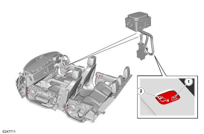
E247711

ItemDescription
1Traffic alert
2Status LED

The CEDS indicator is located adjacent to the door inner handle.

The CEDS system does not inhibit the opening of the door.

The status LED illuminates when the CEDS system is active.

When a perceived threat approaches the host vehicle the amber traffic alert LED illuminates as a warning to the occupant. A perceived threat is a cyclist or other road users approaching from the rear of the vehicle.

Door Module

NOTES:

  • The DDM is shown. The others are similar.
  • Right hand drive vehicle is shown, left hand drive vehicle is similar.
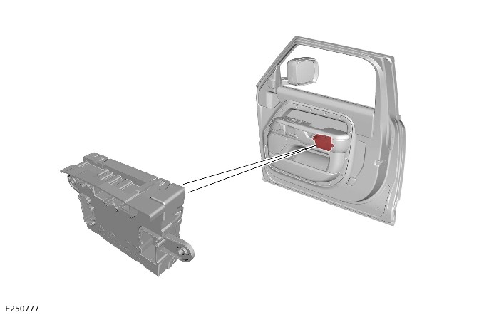
E250777

The door modules require a number of inputs to send the correct message to the CEDS:

  • 'Backlight status'
  • 'Child Lock Cmd (from the door latch)'
  • 'Power Mode'
  • 'Door Status'
  • 'Alert' 'Left RED Alert/Right RED Alert'.

To assess the CEDS indicator and send the correct software message the door modules also requests the following software information from the CEDS indicator:

  • 'CEDSHMIStatus'
  • 'PartNo'
  • 'PartNoBlkNo'.

The door modules then sends the correct software message to the CEDS indicator from the following messages:

  • 'Status' ('StatusLED')
  • 'Traffic' ('TrafficLED')
  • 'Backlight' ('BacklightStatus').

Door Ajar Switch

The following components incorporate an ajar switch:

  • Each door latch
  • The left hood latch
  • Tailgate latch.

The door ajar switch sends the door status message to the BCM/GWM. The status message is then sent to the relevant door module. The each door module uses the information to either illuminate or extinguish the CEDS LEDs. If the door is still open, the LEDs remain illuminated.

For additional information, refer to: Handles, Locks, Latches and Entry Systems (501-14 Handles, Locks, Latches and Entry Systems, Description and Operation).

TouchScreen

NOTE:

Right hand drive vehicle is shown, left hand drive vehicle is similar.
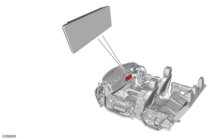
E258293

The touchscreen is located in the center of the instrument panel.

The touchscreen is controlled by the user using touch icons located in the screen image.

For additional information, refer to: Audio System (415-01 Information and Entertainment System, Description and Operation).

OPERATION

BLIND SPOT assist

The blind spot assist operates when following circumstances occur together:

  • A vehicle is detected in the blind spot area.
  • The driver tries to change lanes.

When blind spot assist operates it:

  • Flashes the amber warning alert icon in the related door mirror or provides the solid warning.
  • Applies a rotational force to the steering to keep the vehicle in the current road lane.
  • An optical warning is displayed in the IPC.

Blind spot assist does not operate if REVERSE (R) or PARK (P) is selected.

BLIND SPOT MONITORING

The blind spot assist is an enhancement of BSM.

The BSM uses rear corner radars to detect adjacent lane moving objects and provides the warning on the door mirrors.

The area monitored extends from the door mirrors rearward, to approximately:

  • 8.5 meters from the driver see line (driver able to see the vehicle in the window).
  • Up to 3.5 meters from the side of the vehicle.
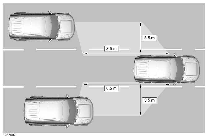
E257607

The driver is alerted with a warning alert icon in the relevant door mirror.

NOTE:

If an over-taking vehicle is detected on both sides of the vehicle simultaneously, the warning alert icons in both door mirrors illuminate.

The LEDs are located towards the outside extremity of the door mirror glass, within the peripheral view of the driver. They are not in any area of the door mirror where they could obscure or distract from the reflected image.

E168593

ItemDescription
1Warning alert icon
2System status warning alert icon

The warning alert icon tells the driver if there is a vehicle in the blind spot area.

The system status warning alert icon tells the driver if there is a fault in the BSM.

The LEDs alerts are as follows:

LED StatusCause
No LED ONSystem active, no vehicle detected in blind spot area.
Amber warning alert icon permanently ONSystem operational, vehicle detected in blind spot area.
Amber warning alert icon flashingSystem operational, vehicle detected in blind spot area, turn signal indicator operated or when vehicle drifts to an adjacent line.
Amber system status warning alert icon permanently ONSystem not active or faulty.

The BSM has operating limitations and automatically turns OFF under certain operating conditions. During these operating conditions, the amber system status warning alert icon is permanently ON.

The BSM system does not operate when:

  • REVERSE (R) or PARK (P) is selected.
  • The vehicle speed is below 10 km/h (6 mph).
  • The radar sensors become blocked or stop working.
  • The door mirrors stop working.
  • An electrical connector is connected to the JLR approved trailer socket.

NOTE:

The blind spot monitor system remains disabled if a trailer is disconnected from the trailer socket while the engine is still running. Switch the vehicle's ignition off, then back on again, to enable the blind spot monitor system.

The BSM system:

  • Works most effectively on multi-lane roads.
  • Monitors an area of approximately 3.3 m from the side of the vehicle, and approximately 8.5 m behind the vehicle.
  • May register false targets if traveling along a narrow lane.
  • Does not work accurately if the sensors are misaligned due to bumper modifications, impact damage, etc.

The instrument panel and touchscreen display messages to inform the driver of any performance or system issues.

The BSM can sense a blockage, if either of the radar signals are blocked or distorted, for example:

  • Water
  • Mud
  • Sleet
  • Snow.

In this situation, the amber system status warning alert icon is permanently ON. A 'Clear rear bumper Driver Assistance feature performance limited' message also displays in the IPC message center. The BSM is disabled until the blockage is cleared.

If there is a fault in the BSM, only the LED alert icon in the door mirror is provided until fault is recovered.

If the communication network fails, it is possible that the system status warning icon cannot be set to ON in the door mirror. The only way to find out is by checking the Diagnostic Trouble Code(s) (DTC). When faults are present in the BSM, DTCs are stored in the SODL and the SODR. If a SODL or a SODR is replaced it must be configured with the JLR approved diagnostic equipment.

APPROACHING VEHICLE SENSING

AVS system is an enhancement of the blind spot monitoring.

The AVS system operates in the same principle as BSM. However AVS monitors a larger area extending from the back of the BSM zone, to approximately:

  • 70 meters behind the door mirrors.
  • Up to 3.5 meters from the side of the vehicle.
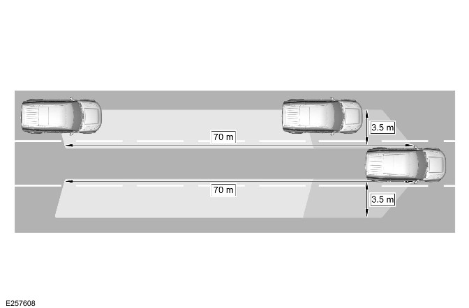
E257608

The system alerts the driver to the presence of a vehicle approaching rapidly beyond the blind spot.

When a vehicle is detected by the AVS system, the following LED lighting sequence occurs:

>td rowspan="1">Permanently ON

Amber warning alert icon LED StatusExplanation
Flashes
The detected vehicle enters the blindspot monitoring area but the relevant turn signal indicator NOT operated.

NOTE:

An amber warning icon is located in each door mirror.

E168595

Reverse Traffic Detection

NOTE:

  • If a fault in a single sensor is detected, the entire feature is disabled.
  • If the rear sensors are blocked, the feature performance is reduced, or the feature may be disabled all together.
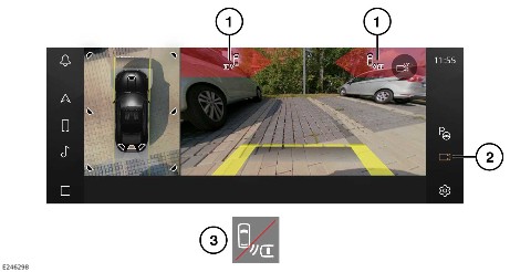
E246298

ItemDescription
1Collision impact alert
2Camera icon
3Rear traffic monitor unavailable

Rear Traffic Warning

NOTE:

If Rear Traffic Warning is switched OFF, the collision impact alert icon does not display, and no audio alerts sound.

The Rear Traffic Warning feature is active when in REVERSE (R). The feature also becomes active from a stationary position and remains active up to speeds of approximately 16 km/h (10 mph).

If required, the Rear Traffic Warning feature can be switched ON or OFF through the driver assistance menu. To switch the Rear Traffic Warning feature ON or OFF, complete the following steps:

  1. Touch the settings icon from any screen
  2. Select 'Vehicle'
  3. Select 'Driver Assistance'
  4. Select 'Collision avoidance'
  5. Touch to switch toggle ON or OFF.

Rear Traffic Braking

NOTE:

If Rear Traffic Braking is switched OFF, the system does not apply the brakes if a imminent collision is detected.

The Rear Traffic Braking feature is active when the vehicle detects reverse movement and remains active up to speeds of approximately 10 km/h (6 mph).

The Rear Traffic Braking feature can also be switched ON or OFF through the driver assistance menu. To switch the Rear Traffic Braking feature ON or OFF, complete the following steps:

  1. Touch the settings icon from any screen
  2. Select 'Vehicle'
  3. Select 'Driver Assistance'
  4. Select 'Collision avoidance'
  5. Touch to switch toggle ON or OFF.

Rear protection monitor

The rear protection monitor system helps identify any potential collision risks from the rear of the vehicle.

The system monitors an area of approximately 80 m behind the vehicle for threats from other vehicles that are approaching the rear at high speeds.

The system warns the driver of the vehicle approaching behind, of any potential collision by flashing the hazards lights rapidly.

The rear protection monitor system default mode is ON and the driver cannot switch the system off.

The rear protection monitor system does not operate when:

  • REVERSE (R) is selected.
  • The relative speed between the host vehicle and threat vehicle is below 10 km/h (6 mph).
  • The sensors in the rear bumper become blocked.
  • A vehicle crash is detected.
  • A trailer is attached and connected.

The rear protection monitor system:

  • May register false targets if traveling along a narrow lane, or in stop and go traffic.
  • Does not work accurately if the sensors are misaligned due to bumper modifications, impact damage, etc.

Lane Keep Assist switch

CAUTION:

Make sure the LKA system is disabled when connecting a trailer.

NOTE:

The blind spot assist feature selection is merged with the LKA switch on the right steering wheel switch.
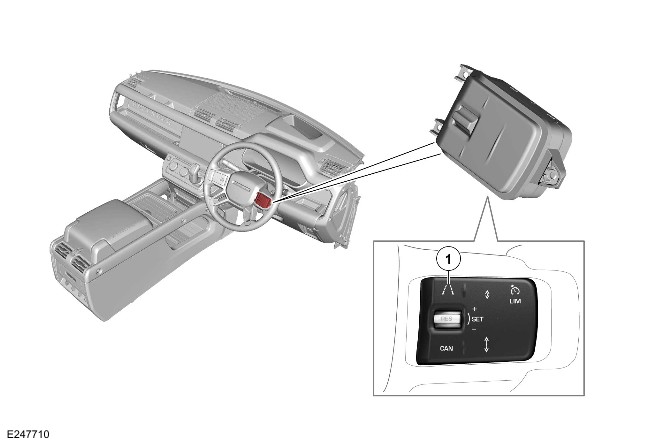
E247710

ItemDescription
1LKA switch

The LKA monitors the road lane markings in the event of an unintentional road lane departure. If the vehicle is about to cross a lane boundary, a rotational force is applied to the steering wheel to counter the lane boundary crossing. The IPC displays a warning icon when a rotational force is applied to the steering wheel.

The LKA system can be switched ON or OFF through the Steering Wheel Switch.

NOTE:

The LKA switch also controls operation of the Blind Spot Assist system. The LKA system selection is retained across all ignition cycles.

Lane Keep Assist status

E246790

The IPC displays an icon when the LKA system is switched ON. The icon changes color as follows:

  1. Gray lines indicate
    • The lane boundaries are not being tracked.
    • The driver is indicating on the same side. When indicating left, the left side only is grayed out. The same strategy applies when indicating right.
    • One or more of the system limitations criteria may have been met.
  2. Green lines indicate
    • The lane boundaries are being tracked.
  3. Red lines indicate.
    • When the LKA feature is intervening.

LKA status can also be viewed through the 'Driver Assistance' IPC view. The HUD also displays a warning.

NOTE:

If a system fault has been detected with the IPC or HUD, the LKA continues to operate as intended.

The LKA system is not active when:

  • REVERSE (R) or PARK (P) is selected.
  • The brake pedal is pressed.
  • A turn signal indicator is being used.
  • The road lanes are not available or in poor condition.
  • The road lane markings are not detected.
  • The vehicle speed is approximately below 64 km/h (40 mph) or above 180 km/h (112 mph).
  • Driving in lanes narrower than approximately 3 meters or wider than approximately 4 meters.
  • Turning in tight road bends.
  • Dynamic Stability Control (DSC) is active.
  • An Anti-Lock Brake System Control Module (ABS) event has occurred.
  • A fault occurs in the system.
  • The driver has applied excessive steering force.

The LKA system does not operate if:

  • The road edges are unmarked.
  • The windshield area in front of the rear view mirror becomes blocked by stickers, mud, snow, debris, etc.
  • Adverse weather conditions exist. For example, heavy fog, rain, or snow.
  • The driver has applied a counter steering input that is greater than the steering input from the LKA system.

The IPC displays messages to inform the driver of any performance or system issues.

EMERGENCY LANE KEEP ASSIST

CAUTION:

Make sure the ELKA system is disabled when connecting a trailer.

NOTE:

The ELKA system automatically switches ON every time the vehicle ignition is switched ON.

The ELKA system attempts to provide corrective steering inputs if it determines the following:

  • The vehicle is getting too close to horizontal road edges. For example, grass, mud and snow.
  • The vehicle is getting too close to vertical road edges. For example, cones, concrete barriers, walls and parked vehicles.
  • The vehicle is drifting towards an adjacent lane where oncoming vehicles are detected.

NOTE:

ELKA operates irrespective of the use of the turn signal indicators.

The ELKA system can be switched ON or OFF through the touchscreen. To switch the system ON or OFF, complete the following steps:

  1. Touch the settings icon from any screen
  2. Select 'Vehicle'
  3. Select 'Driver Assistance'
  4. Select 'Collision avoidance'
  5. Touch the 'Emergency Steering' Switch to toggle ON or OFF.

NOTE:

Make sure the ELKA system is switched OFF before driving off-road.

The IPC displays visual warnings to inform the driver of the ELKA system status. The vehicle speakers also provides audio warnings.

NOTE:

ELKA feature detecting oncoming vehicles is only operational when detecting an oncoming vehicle in an adjacent road lane.

If a system fault has been detected with the IPC or HUD, the ELKA continues to operate as intended.

The ELKA system is not active when:

  • REVERSE (R) or PARK (P) is selected.
  • The brake pedal is pressed.
  • The vehicle speed is approximately:
  • Below 64 km/h (40 mph) or above 180 km/h (112 mph) when ELKA is detecting road edges.
  • Below 64 km/h (40 mph) or above 120 km/h (75 mph) when ELKA is detecting oncoming vehicles.
  • The road edges are not detected.
  • Turning in tight road bends.
  • The driver has applied excessive steering force.
  • Driving in lanes narrower than approximately 3 meters or wider than approximately 4 meters.
  • A fault occurs in the system.

The ELKA system does not operate if:

  • The windshield area in front of the rear view mirror becomes blocked by stickers, mud, snow, debris.
  • Adverse weather conditions exist. For example, heavy fog, rain, or snow.
  • DSC is active.
  • An ABS event has occurred.
  • The driver has applied a counter steering input that is greater than the steering input from the ELKA system.

The IPC displays messages to inform the driver of any performance or system issues.

Traffic Sign Recognition

The IPC displays symbols of recognized traffic signs. If no speed limit signs are visible, the IPC displays speed limit information taken from the navigation system.

The traffic sign recognition system is also able to detect traffic signs containing additional information. For example, the system is able to detect if a reduced speed limit is in place for wet conditions, and the wipers are switched on. In this instance, the reduced speed limit is displayed in the IPC.

The traffic sign recognition system does not operate to the optimum performance, if the windshield area in front of the rear-view mirror becomes blocked. For example, by stickers, mud, snow, debris.

The traffic sign recognition continues to operate using the vehicle navigation map information.

The traffic sign recognition system:

  • Does not perform to the best of its ability in adverse weather conditions. For example, heavy fog, rain, or snow.
  • May not perform, or may perform incorrectly, when the vehicle is traveling through an area not covered by the navigation system.
  • May function incorrectly when driving toward bright lights.
  • May not recognize concealed, covered, or non-conforming road signs.
  • May not perform to the best of its ability if the navigation maps are out of date.

The IPC and touchscreen display messages to inform the driver of any performance or system issues.

Driver Condition Monitor
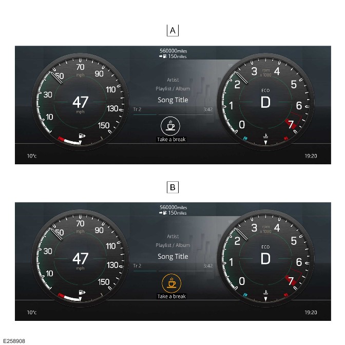
Driver fatigue alert
E258908

ItemDescription
AFatigued - White
BHighly fatigued - Amber

In the event of the driver becoming fatigued:

  • The IPC displays a white icon. The IPC also emits a chime.
  • The Driver Condition Monitor feature may warn the driver every 5 minutes if the driver continues to be fatigued.

In the event of the driver becoming highly fatigued:

  • The IPC displays an amber icon. The IPC also emits a chime.
  • The Driver Condition Monitor feature may warn the driver every 10 minutes if the driver continues to be highly fatigued.

NOTE:

The icon remains illuminated until the OK button on the steering wheel is pressed.

The Driver Condition Monitor feature can be switched ON or OFF through the touchscreen. To switch the feature ON or OFF, complete the following steps:

  • Touch the 'SETTINGS' icon from any screen.
  • Select 'Vehicle'
  • Select 'Driver Assistance'
  • Select 'Driver condition monitor'
  • Driver fatigue alert: Touch to switch toggle ON or OFF.
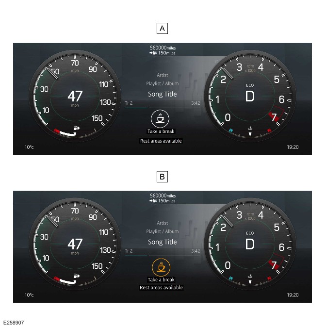
Find rest areas
E258907

ItemDescription
AFatigued - White
BHighly fatigued - Amber

The Driver Condition Monitor feature can also find nearby rest areas, if selected, for when the driver becomes fatigued.

The IPC notifies the driver that rest areas are available nearby. The rest areas display on the touchscreen.

NOTE:

The find rest areas feature selection is retained across all ignition cycles.

To switch the feature ON or OFF, complete the following steps:

  • Touch the 'SETTINGS' icon from any screen.
  • Select 'Vehicle'
  • Select 'Driver Assistance'
  • Select 'Driver condition monitor'
  • Find rest areas: Touch to switch toggle ON or OFF.

The Driver Condition Monitor is not active when:

  • The vehicle speed is below 60 km/h (37 mph) or above 180 km/h (112 mph).
  • A fault occurs in the system.

Clear Exit Detection System

CAUTION:

Make sure that the warning icons on the door handle are not obscured. If the warning icons are not visible, the user may not notice a warning, which may cause damage to the vehicle.

Do not attach stickers or objects to the rear bumper. Stickers and other attachments may interfere with the operation of the clear exit detection sensors.

The clear exit detection system activates only when the door has been unlatched. The icons illuminate as follows:
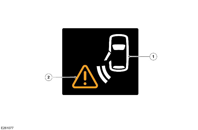
E261077

  1. Illuminates white to indicate that the system is active.
  2. Illuminates amber to warn of a detected threat.

The amber icon illuminates when another vehicle or moving object is detected as approaching from behind. The system has calculated that opening the door could endanger the occupant, the vehicle or other road users. The system does not prevent the door from being opened. The icons extinguish after the door has been closed.

The CEDS may not be able to detect all approaching traffic in all circumstances. Operation of the system relies on the sensor ability to detect threats, which may be affected by road and weather conditions, but also if:

  • Vehicles approach very quickly from behind.
  • The sensors are impaired by mud, rain, frost, ice, snow, damage, accessories or stickers.
  • The sensors are obscured by objects, such as towed items, or other vehicles close to the vehicle.

Under these circumstances, reduced warning times or loss of functionality may be experienced.

Clear exit monitor is only active below vehicle speeds of 5 km/h (3 mph). The CEDS remains active for 3 minutes after the ignition is switched OFF.

DIAGNOSTICS

The BCM/GWM records any DTCs and related data. Read the DTCs and related data with the JLR approved diagnostic equipment. For additional information, refer to: Diagnostic Trouble Code Index - DTC: Body Control Module (BCM) (100-00 General Information, Description and Operation).

The JLR approved diagnostic equipment can read live data and activate certain components.

CONTROL DIAGRAM

Control Diagram - 1 of 6 - BLIND SPOT ASSIST
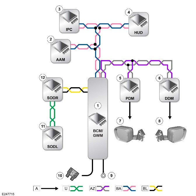
E247715

A = Hardwired: U = Private CAN bus: AZ = HS CAN body systems bus: BA= HS CAN Human Machine Interface (HMI) systems bus: BL = HS CAN UN systems bus.

ItemDescription
1BCM/GWM
2AAM
3IPC
4HUD
5PDM
6DDM
7Approaching vehicle lamp - Left door mirror
8Approaching vehicle lamp - Right door mirror
9Ground
10Power supply
11SODL
12SODR

Control Diagram - 2 of 6 - Reverse Traffic Detection
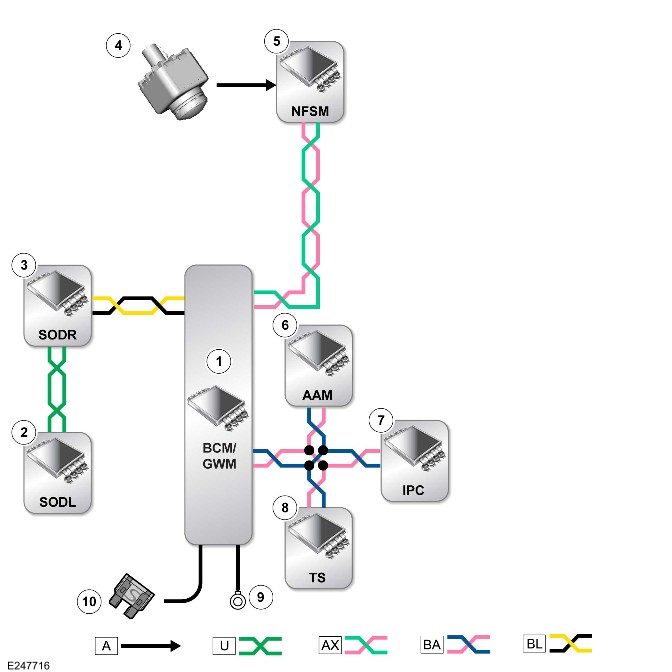
E247716

A = Hardwired: U = Private CAN bus: AX = FlexRay: BA= HS CAN HMI systems bus: BL = HS CAN UN systems bus.

ItemDescription
1BCM/GWM
2SODL
3SODR
4Rear view camera
5NFSM
6AAM
7IPC
8Touchscreen
9Ground
10Power supply

Control Diagram - 3 of 6 - LANE KEEP ASSIST
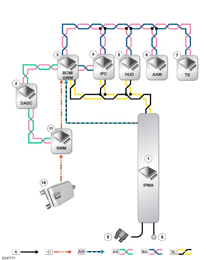
E247717

A = Hardwired: O = Local Interconnect Network (LIN): AW = Ethernet: AX = FlexRay: BA= HS CAN HMI systems bus: BL = HS CAN UN systems bus.

ItemDescription
1IPMA
2DADC
3BCM/GWM
4IPC
5HUD
6AAM
7Touchscreen
8Ground
9Power supply
10Steering wheel switch
11SWM

Control Diagram - 4 of 6 - Traffic Sign Recognition
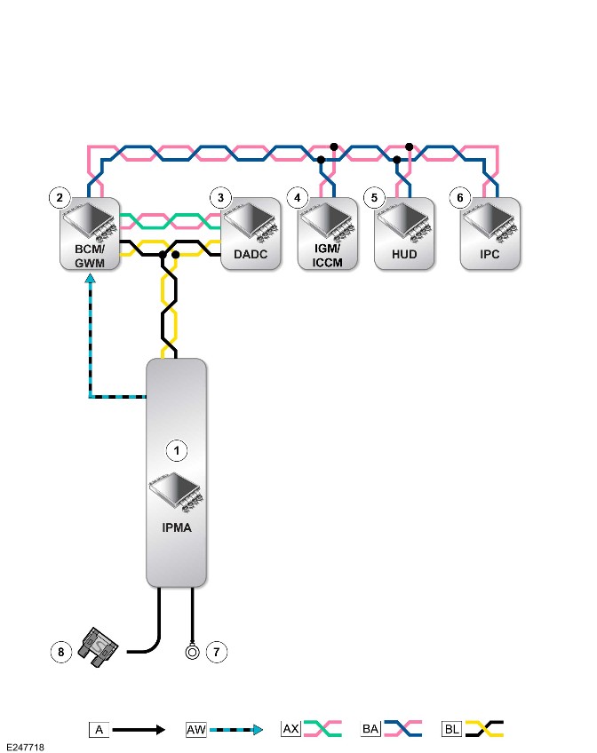
E247718

A = Hardwired: AW = Ethernet: AX = FlexRay: BA= HS CAN HMI systems bus: BL = HS CAN UN systems bus.

ItemDescription
1IPMA
2BCM/GWM
3DADC
4IGM / ICCM
5HUD
6IPC
7Ground
8Power supply

Control Diagram - 5 of 6 - Driver Condition Monitor
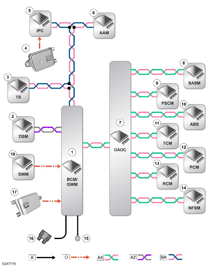
E247719

A = Hardwired: O = LIN: AX = FlexRay: AZ = HS CAN BODY systems bus: BA= HS CAN HMI systems bus.

ItemDescription
1BCM/GWM
2DSM
3Touchscreen
4Steering wheel switch - Left
5IPC
6AAM
7DADC
8Steering Angle Sensor Control Module (SASM)
9PSCM
10ABS
11TCM
12PCM
13RCM
14NFSM
15Ground
16Power supply
17Steering wheel switch - Right
18SWM

Control Diagram - 6 of 6 - Clear Exit Detection System
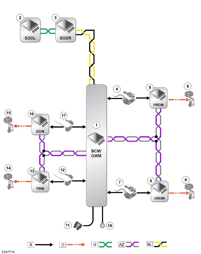
E247714

A = Hardwired: O = LIN: U = Private CAN bus: AZ = HS CAN BODY systems bus: BL = HS CAN UN systems bus.

ItemDescription
1BCM/GWM
2SODL
3SODR
4Door ajar switch - Rear left door
5PRDM
6CEDS LED indicator - Rear left
7Door ajar switch - Rear right door
8DRDM
9CEDS LED indicator - Rear left
10Ground
11Power supply
12Door ajar switch - Passenger door
13PDM
14CEDS LED indicator - Passenger door
15CEDS LED indicator - Driver door
16DDM
17Door ajar switch - Driver door

Battery and Charging System - General Information (G2323766)

SPECIFICATIONS

Startup battery

ItemSpecifications
TypeAbsorbed glass mat (AGM)
Capacity90 Ah
Cold cranking amps850 CCA
Reserve capacity150 minutes

Startup battery disconnect/connect

CAUTIONS:

  • The vehicle status and start up battery condition must be established before attempting battery disconnect/connect. Reference must then be made to the following table to establish the relevant procedure to be followed.
  • After connecting the start up battery, the steering wheel must be turned to full left-hand and full right-hand lock with the engine running. This allows the dynamic stability control system to calibrate the steering wheel position. Failure to follow this instruction may result in a variety of Instrument Panel Cluster (IPC) warning lamps being illuminated.

NOTES:

  • If there is insufficient capacity in the startup battery to disarm the alarm, the alarm may sound on connection of the startup battery - turning the ignition key to position II will disarm the alarm.
  • If a new startup battery is installed, the startup Battery Monitoring System (BMS) must be reset using Jaguar Land Rover approved diagnostic equipment.
Vehicle statusBattery chargedBattery discharged
-ProcedureProcedure
Vehicles without Telematics--
Engine running1-
Vehicle powered down, locked and alarmed23
Vehicle unlocked45
Vehicles with Telematics--
Engine running6-
Vehicle powered down, locked and alarmed78
Vehicle unlocked910
Connecting the startup battery positive cable
E218460

Procedure 1

Disconnect the batteryConnect the battery
1. If possible, apply the parking brake or chock the wheels.1. Make sure that all the electrical systems and ignition are switched OFF.
2. Set the ignition to the OFF position.2. Connect the battery GROUND cable.
3. Wait 2 minutes for the engine management system to POWER DOWN.3. Reset electric window one-touch facility. Power window up to hard stop, release switch, reapply and hold for 1 second, (relay in door will click). One touch should now work.
4. Disconnect the battery GROUND cable.4. Using suitable Land Rover diagnostic equipment calibrate the electric park brake and tailgate. Check the clock and navigation settings.

Procedure 2

Disconnect the batteryConnect the battery
1. Unlock the vehicle and disarm the alarm using the UNLOCK button on the key fob.1. Make sure that all the electrical systems and ignition are switched OFF.
2. Enter the vehicle. Set the ignition to the ON position. Apply the parking brake or chock the wheels and then set the ignition to the OFF position.2. Connect the battery GROUND cable.
3. Wait 2 minutes for the engine management system to POWER DOWN.3. Reset electric window one-touch facility. Power window up to hard stop, release switch, reapply and hold for 1 second, (relay in door will click). One touch should now work.
4. Disconnect the battery GROUND cable.4. Using suitable Land Rover diagnostic equipment calibrate the electric park brake and tailgate. Inspect the clock and navigation settings.

Procedure 3

Disconnect the batteryConnect the battery
1. Unlock the vehicle from the driver's door using the key.1. Make sure that all the electrical systems and ignition are switched OFF.
2. Enter the vehicle. Apply the parking brake or chock the wheels.2. Connect the battery GROUND cable.
3. Disconnect the battery GROUND cable.3. Set the ignition to the ON position.
 4. Reset electric window one-touch facility. Power window up to hard stop, release switch, reapply and hold for 1 second, (relay in door will click). One touch should now work.
 5. Using suitable Land Rover diagnostic equipment calibrate the electric park brake and tailgate. Inspect the clock and navigation settings.

Procedure 4

Disconnect the batteryConnect the battery
1. Enter the vehicle. Set the ignition to the ON position. Apply the parking brake or chock the wheels and then set the ignition to the OFF position.1. Make sure that all the electrical systems and ignition are switched OFF.
2. Wait 2 minutes for the engine management system to POWER DOWN.2. Connect the battery GROUND cable.
3. Disconnect the battery GROUND cable.3. Reset electric window one-touch facility. Power window up to hard stop, release switch, reapply and hold for 1 second, (relay in door will click). One touch should now work.
 4. Using suitable Jaguar Land Rover diagnostic equipment calibrate the electric park brake and tailgate. Check the clock and navigation settings.

Procedure 5

Disconnect the batteryConnect the battery
1. Enter the vehicle. Apply the parking brake or chock the wheels.1. Make sure that all the electrical systems and ignition are switched OFF.
2. Disconnect the battery GROUND cable.2. Connect the battery GROUND cable.
 3. Set the ignition to the ON position.
 4. Reset electric window one-touch facility. Power window up to hard stop, release switch, reapply and hold for 1 second, (relay in door will click). One touch should now work.
 5. Using suitable Jaguar Land Rover diagnostic equipment calibrate the electric park brake and tailgate. Check the clock and navigation settings.

Procedure 6

Disconnect the batteryConnect the battery
1. Make sure the customer has placed stolen vehicle tracking into Service Mode, (if equipped).1. Make sure that all the electrical systems and ignition are switched OFF.
2. If possible, apply the parking brake or chock the wheels.2. Connect the battery GROUND cable.
3. Set the ignition to the OFF position.3. Reset electric window one-touch facility. Power window up to hard stop, release switch, reapply and hold for 1 second, (relay in door will click). One touch should now work.
4. Wait 2 minutes for the engine management system to POWER DOWN.4. Using suitable Jaguar Land Rover diagnostic equipment calibrate the electric park brake and tailgate. Check the clock and navigation settings.
5. Disconnect the battery GROUND cable.5. Request stolen vehicle tracking removed from Service Mode, (if equipped).

Procedure 7

Disconnect the batteryConnect the battery
1. Make sure the customer has placed stolen vehicle tracking into Service Mode, (if equipped).1. Make sure that all the electrical systems and ignition are switched OFF.
2. Unlock the vehicle and disarm the alarm using the UNLOCK button on the key fob.2. Connect the battery GROUND cable.
3. Enter the vehicle. Set the ignition to the ON position. Apply the parking brake or chock the wheels and then set the ignition to the OFF position.3. Reset electric window one-touch facility. Power window up to hard stop, release switch, reapply and hold for 1 second, (relay in door will click). One touch should now work.
4. Wait 2 minutes for the engine management system to POWER DOWN.4. Using suitable Jaguar Land Rover diagnostic equipment calibrate the electric park brake and tailgate. Check the clock and navigation settings.
5. Disconnect the battery GROUND cable.5. Request stolen vehicle tracking removed from Service Mode, (if equipped).

Procedure 8

CAUTION:

Battery discharge may have activated the stolen vehicle tracking, check with customer if equipped.

Disconnect the batteryConnect the battery
1. Make sure the customer has placed stolen vehicle tracking into Service Mode, (if equipped).1. Make sure that all the electrical systems and ignition are switched OFF.
2. Unlock the vehicle from the driver's door using the key.2. Connect the battery GROUND cable
3. Enter the vehicle. Apply the parking brake or chock the wheels.3. Set the ignition to the ON position.
4. Disconnect the battery GROUND cable.4. Reset electric window one-touch facility. Power window up to hard stop, release switch, reapply and hold for 1 second, (relay in door will click). One touch should now work.
 5. Using suitable Jaguar Land Rover diagnostic equipment calibrate the electric park brake and tailgate. Check the clock and navigation settings.
 6. Request stolen vehicle tracking removed from Service Mode, (if equipped).

Procedure 9

Disconnect the batteryConnect the battery
1. Make sure the customer has placed stolen vehicle tracking into Service Mode, (if equipped).1. Make sure that all the electrical systems and ignition are switched OFF.
2. Enter the vehicle. Set the ignition to the ON position. Apply the parking brake or chock the wheels and then set the ignition to the OFF position.2. Connect the battery GROUND cable.
3. Wait 2 minutes for the engine management system to POWER DOWN.3. Reset electric window one-touch facility. Power window up to hard stop, release switch, reapply and hold for 1 second, (relay in door will click). One touch should now work.
4. Disconnect the battery GROUND cable.4. Using suitable Jaguar Land Rover diagnostic equipment calibrate the electric park brake and tailgate. Check the clock and navigation settings.
 5. Request stolen vehicle tracking removed from Service Mode, (if equipped).

Procedure 10

CAUTION:

Battery discharge may have activated the stolen vehicle tracking, check with customer if equipped.

Disconnect the batteryConnect the battery
1. Make sure the customer has placed stolen vehicle tracking into Service Mode, (if equipped).1. Make sure that all the electrical systems and ignition are switched OFF.
2. Enter the vehicle. Apply the parking brake or chock the wheels.2. Connect the battery GROUND cable.
3. Disconnect the battery GROUND cable.3. Set the ignition to the ON position.
 4. Reset electric window one-touch facility. Power window up to hard stop, release switch, reapply and hold for 1 second, (relay in door will click). One touch should now work.
 5. Using suitable Jaguar Land Rover diagnostic equipment calibrate the electric park brake and tailgate. Check the clock and navigation settings.
 6. Request stolen vehicle tracking removed from Service Mode, (if equipped).

Vehicle Jump (Emergency) Starting - Using Another Vehicle

WARNINGS:

  • Take care when working near rotating parts of the engine.
  • Prior to attempting to start the disabled vehicle, make sure that the parking brake is applied or suitably chock the wheels. Make sure that 'P' - PARK - Automatic Transmission or NEUTRAL - Manual Transmission is selected.
  • Suitable eye protection must be worn when working in the vicinity of the battery.
  • DO NOT attempt to start the disabled vehicle if it is suspected that the electrolyte in the battery is frozen.
  • During normal use, batteries emit explosive hydrogen gas sufficient to cause severe explosions and capable of causing serious injury - keep sparks and open flames away from the engine compartment.

CAUTIONS:

  • Make sure that there is no physical contact between the donor and disabled vehicles other than the booster cables.
  • Make sure that the slave battery/starting aid is of the 12 volt type.
  • Make sure that all electrical systems and ignition are switched OFF prior to connecting the booster cables.
  • Disconnect the booster cables prior to operating any electrical systems.
Vehicle statusProcedure
Vehicles without Telematics1
Vehicles with Telematics2

Procedure 1

Complete the following operations in the sequence given
1. Connect one end of the RED (+) booster cable to the POSITIVE (+) jump start terminal of the DONOR vehicle
2. Connect the other end of the RED (+) booster cable to the POSITIVE (+) jump start terminal of the DISABLED vehicle
3. Connect one end of the BLACK (-) booster cable to the GROUND (-) jump start terminal of the DONOR vehicle
4. Connect the other end of the BLACK (-) booster cable to the GROUND (-) jump start terminal on the DISABLED vehicle
5. Start the engine of the DONOR vehicle and allow it to idle for a few minutes
6. Start the engine of the DISABLED vehicle
7. Allow the engines of both vehicles to idle for a few minutes, then switch off the engine of the DONOR vehicle
8. Disconnect the BLACK (-) booster cable from the jump start terminal of the PREVIOUSLY DISABLED vehicle
9. Disconnect the BLACK (-) booster cable from the jump start terminal of the DONOR vehicle
10. Disconnect the RED (+) booster cable from the jump start terminal of the PREVIOUSLY DISABLED vehicle
11. Disconnect the RED (+) booster cable from the jump start terminal of the DONOR vehicle

Procedure 2

Complete the following operations in the sequence given
1. Make sure the customer has placed stolen vehicle tracking into Service Mode, (if equipped).
1. Connect one end of the RED (+) booster cable to the POSITIVE (+) jump start terminal of the DONOR vehicle
2. Connect the other end of the RED (+) booster cable to the POSITIVE (+) jump start terminal of the DISABLED vehicle
3. Connect one end of the BLACK (-) booster cable to the GROUND (-) jump start terminal of the DONOR vehicle
4. Connect the other end of the BLACK (-) booster cable to the GROUND (-) jump start terminal on the DISABLED vehicle
5. Start the engine of the DONOR vehicle and allow it to idle for a few minutes
6. Start the engine of the DISABLED vehicle
7. Allow the engines of both vehicles to idle for a few minutes, then switch off the engine of the DONOR vehicle
8. Disconnect the BLACK (-) booster cable from the GROUND (-) jump start terminal of the PREVIOUSLY DISABLED vehicle
9. Disconnect the BLACK (-) booster cable from the jump start terminal of the DONOR vehicle
10. Disconnect the RED (+) booster cable from the POSITIVE (+) jump start terminal of the PREVIOUSLY DISABLED vehicle
11. Disconnect the RED (+) booster cable from the jump start terminal of the DONOR vehicle
12. Request stolen vehicle tracking removed from Service Mode, (if equipped).

Vehicle Jump (Emergency) Starting - Using a Slave Battery/Starting Aid

Vehicle statusProcedure
Vehicles without Telematics1
Vehicles with Telematics2

Procedure 1

Complete the following operations in the sequence given
1. Connect the end of the RED (+) booster cable to the POSITIVE (+) jump start terminal of the vehicle.
2. Connect the end of the BLACK (-) booster cable to the GROUND (-) jump start terminal of the vehicle.
3. Start the engine of the vehicle and allow it to idle.
4. Disconnect the BLACK (-) booster cable from the GROUND (-) jump start terminal of the vehicle.
5. Disconnect the RED (+) booster cable from the POSITIVE (+) jump start terminal of the vehicle.

Procedure 2

Complete the following operations in the sequence given
1. Make sure the customer has placed stolen vehicle tracking into Service Mode, (if equipped).
2. Connect the end of the RED (+) booster cable to the POSITIVE (+) jump start terminal of the vehicle.
3. Connect the end of the BLACK (-) booster cable to the GROUND (-) jump start terminal of the vehicle.
4. Start the engine of the vehicle and allow it to idle.
5. Disconnect the BLACK (-) booster cable from the GROUND (-) jump start terminal of the vehicle.
6.Disconnect the RED (+) booster cable from the POSITIVE (+) jump start terminal of the vehicle.
7. Request stolen vehicle tracking removed from Service Mode, (if equipped).

12V Li-Ion Startup Battery (G4586646)

DESCRIPTION AND OPERATION

Component Location

COMPONENT LOCATION - 1 OF 1.

NOTE:

right hand drive (RHD) vehicle is shown, left hand drive (LHD) vehicle is similar.
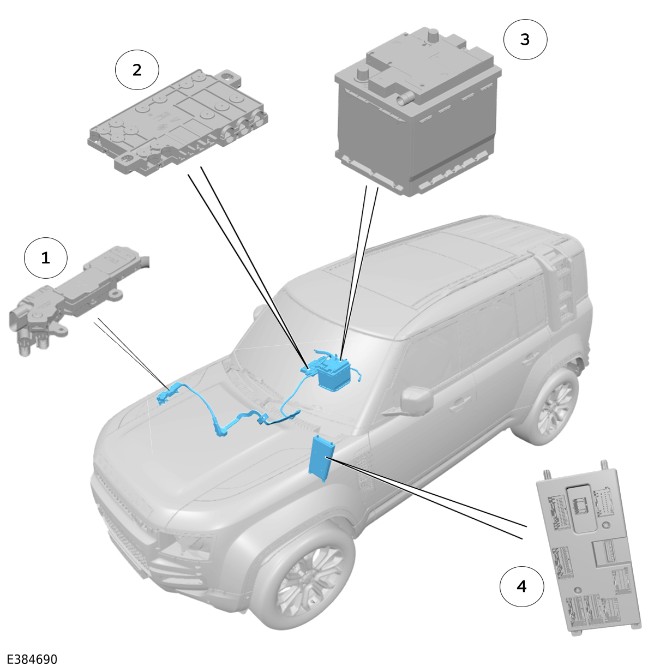
E384690

ItemDescription
1Positive jump start terminal in auxiliary junction box
212V Battery Junction Box (BJB)
312V Lithium-ion (Li-ion) starter battery
4Body Control Module (BCM)/ Gateway Module A (GWM)

The 12V Li-ion starter battery and BJB are located under the right front seat and separated from the interior by a plastic cover.

Overview

12V (LI-ION) STARTER BATTERY

CAUTION:

The 12V Li-ion starter battery contains Jaguar Land Rover (JLR) specific software, so must be sourced from the retailer.

NOTE:

A 12V Li-ion battery has a relatively high terminal voltage at a low State Of Charge (SOC), therefore measuring the terminal voltage alone is not a reliable SOC indicator.
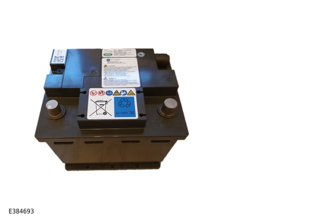
E384693

Typical Li-ion open circuit voltage at 25°CSOC >#/th###
13.7100
13.390
13.380
13.270
13.260
13.250
13.240
1330
12.920
12.810
10.10
Near 0Level 2 or 3 open relay

Using a 12V Li-ion starter battery has the following advantages:

  • Lighter and smaller than an equivalent lead acid battery of the same capacity.
  • Can accept many more charge cycles than a lead acid battery, so can last the life of the vehicle.
  • Is able to monitor and balance the internal battery cells to improve longevity.
  • Provides a higher terminal voltage at a lower SOC than a lead acid battery.
  • Can reach full charge much faster than a lead acid battery.
  • Improved diagnostic capability as the Starter Battery Unit (SBU) can report diagnostic information to the BCM/GWM.

12V (LI-ION) STARTER BATTERY - INTERNAL COMPONENTS
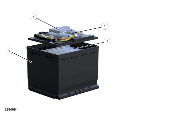
E384694

ItemDescription
1Battery casing
2Internal isolation relay
3SBU
4Li-ion cells

The use of the external Battery Monitoring Sensor (BMS) on the battery ground post is no longer required, as an internal SBU is used to monitor the battery SOC.The SBU is connected to the BCM/GWM through a Local Interconnect Network (LIN) bus connection.

The SBU reports the battery SOC and can be read using the JLR approved diagnostic equipment.

Each of the 4 battery cells have a nominal voltage of 3.5V.

The 12V (Li-Ion) starter battery cannot be dismantled. There are no serviceable components inside the battery.

INTERNAL ISOLATION RELAY

NOTE:

Li-ion batteries are sealed for life and require no maintenance. Do not attempt to open or remove the top from a Li-ion battery.
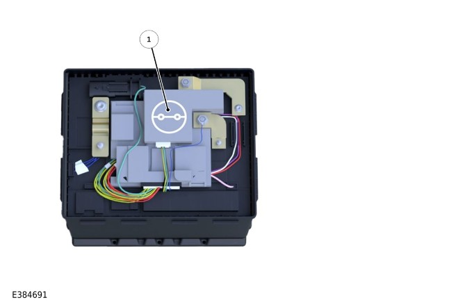
E384691

ItemDescription
1Internal isolation relay

The 12V Li-ion starter battery is sensitive to voltage and current and contains an isolation relay to protect the battery from the following:

  • Low voltage
  • Over voltage
  • Over charging voltage
  • High discharge current
  • High temperature

If the isolation relay opens, a value near 0V will be measured across the battery terminals

This may not be a battery fault as the isolation relay opens to protect the battery

To identify why the relay has opened, connect a JLR approved (BSU) and the JLR approved diagnostic equipment to do the 'Battery Test'

For additional information refer to Vehicle 12V Circuit Recovery

For additional information refer to Quick-learn video 12V Li-ion Battery Training - Part 1 - QDA103066 in Excellence: https://lms.JLRexcellence.com/...

IDENTIFY (LI-ION) BATTERY VEHICLES
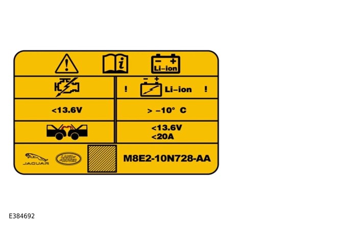
E384692

It is possible to identify a vehicle with a Li-ion battery by the label under the hood.

The label identifies that a 12V Li-ion battery is installed to the vehicle.

The label also shows reference values for jump starting from another vehicle.

Description

12V (LI-ION) STARTER BATTERY - EXTERNAL COMPONENTS

NOTE:

RHD vehicle is shown, LHD vehicle is similar.
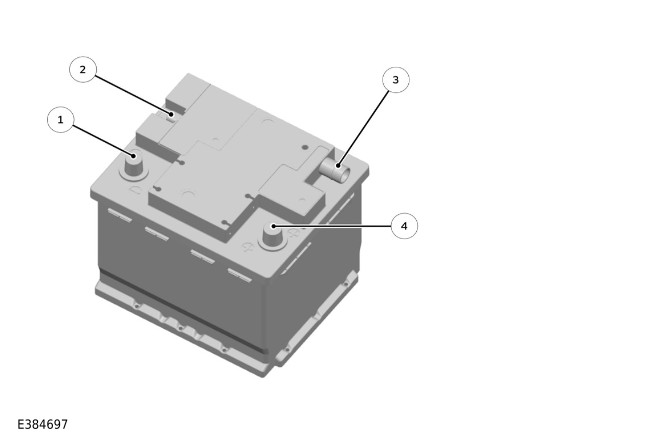
E384697

ItemDescription
1Negative terminal
2LIN connection from the SBU to the BCM/ GWM
3Breather pipe
4Positive terminal

The internal SBU is powered by the battery itself.

The startup battery SBU does not require a procedure to recalibrate if the battery has been taken out from a vehicle and refitted during service.

The SBU has a single 2-pin connector to the wiring harness. The 2-pin connector has the following electrical connections:

  • Pin 1 - LIN connection to the BCM/GWM.
  • Pin 2 - A 12V power supply directly from the starter battery

The SBU monitors the positive and negative current, voltage and temperature to maintain correct operation of the 12V systems.

The SBU communicates with the BCM/GWM on the LIN bus. The BCM/GWM transmits the starter battery information over the Controller Area Network (CAN) and Flexray bus to other vehicle systems.

BCM/GWM
E384698

The BCM/GWM is the main controller of the vehicle body systems.

The Body Control Module/Gateway Module (BCM/GWM) contains software to control the following functions:

  • Determine the condition of the starter battery.
  • Control the Direct Current to Direct Current (DC/DC) converter output to reach a desired system voltage or target 12V battery SOC.
  • Load management: Load management controls the 12V power system to make sure that the charging system is not overloaded. In certain events, for example, during engine stop/start, some systems can be switched off.

For additional information, refer to: Starting System (303-06 Starting System - V8 T/C 4.4L Petrol, Description and Operation).

BATTERY CHARGING AND EMERGENCY STARTING

WARNINGS:

  • Always use one of the JLR approved emergency starting tools for Li-ion batteries. Emergency starting the vehicle with the use of a jump start tool with an excessively high current output is likely to cause a level 3 open relay fault.
  • This would require a battery replacement which may not be covered under the warranty of the vehicle.
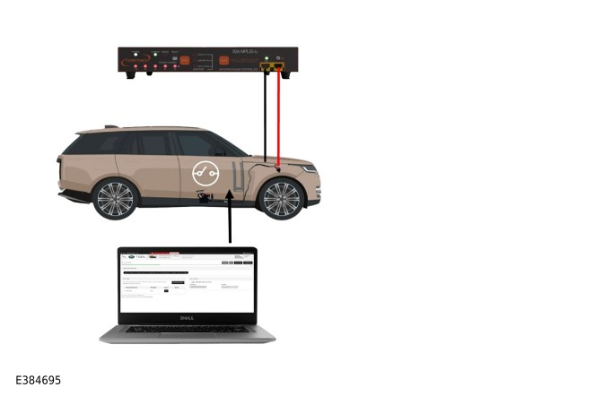
E384695

Always use a jump start pack that meets the specifications for 12V Li-ion startup batteries.

Jump start terminals are provided in the engine compartment.

When jump starting is required, the cover must be removed and the positive jump lead attached securely. The cover must be installed to the positive terminal when not in use.

The vehicle body ground terminal is located on the right side of the engine compartment. When connecting a JLR approved power supply to the vehicle, use the vehicle body ground terminal.

Emergency starting can also be performed using the Vehicle 12V Circuit Recovery Procedure.

For additional information refer to: Quick-learn video 12V Li-ion Battery Training - Part 2 - QDA103094 in Excellence: https://lms.JLRexcellence.com/...

AVAILABLE PROCEDURES

Battery Support Procedure:

This procedure is intended to replenish the Voltage/Current consumed during a workshop session, to maintain the battery SOC.

It is assumed that the vehicle is being interacted with therefore the vehicle is likely to consume some of the current before reaching the battery.

For additional information, refer to: Battery Support Procedure - Vehicles With: 12V Li-Ion Startup Battery (414-00 Battery and Charging System - General Information, General Procedures).

Battery Charge Procedure:

This procedure is intended to increase the battery SOC

The charging rate may be lower as it is intended to maintain the health of the battery.

It is assumed that there will be no interaction with the vehicle therefore charge will primarily be received by the battery.

In vehicle: Maximum allowable charge rate in this mode.

Out of vehicle: Limited to a 20A default current as the battery temperature is unknown when out of the vehicle.

For additional information refer to Battery Charge Procedure - Vehicles With 12V Li-ion Startup Battery

For additional information refer to: Quick-learn video 12V Li-ion Battery Training - Part 2 - QDA103094 in Excellence: https://lms.JLRexcellence.com/...

Vehicle 12V Circuit Recovery:

This procedure is intended to provide an external power supply where the vehicle battery is in a 'open relay' state.

This allows the JLR approved diagnostic equipment to be connected to determine if the startup battery is in a level 2 or level 3 failure mode.

This will also increase the SOC.

A battery charge procedure must be performed if instructed to by the JLR approved diagnostic equipment.

For additional information refer to: Quick-learn video 12V Li-ion Battery Training - Part 2 - QDA103094 in Excellence: https://lms.JLRexcellence.com/...

Emergency Starting Procedure:

This procedure is intended for starting a vehicle where the Vehicle 12V Circuit Recovery procedure is not possible.

Always use a jump start pack that meets the specifications for 12V Li-ion startup batteries.

Dependant on the status of the vehicle onboard charging system 12V generator or DC/DC, the vehicle may not maintain a running state when disconnected.

WARNINGS:

  • Always use one of the JLR approved emergency starting tools for Li-ion batteries. Emergency starting the vehicle with the use of a jump start tool with an excessively high current output is likely to cause a level 3 open relay fault.
  • This would require a battery replacement which may not be covered under the warranty of the vehicle.

There are two JLR approved emergency starting tools currently available.

For additional information, refer to: Emergency Starting Procedure (414-00 Battery and Charging System - General Information, General Procedures).

EMERGENCY STARTING TOOL - NOCO
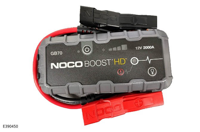
E390450

EMERGENCY STARTING TOOL - PROJECTA
CAUTION:

The Projecta unit is capable of 24V emergency start but MUST NOT be selected for JLR vehicles.
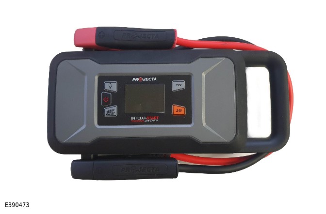
E390473

COLD TEMPERATURE CHARGING

CAUTION:

Charging a 12V Li-ion battery with an excessive current in cold temperatures can reduce its capacity.
E384696

If the JLR approved diagnostic equipment determines that the 12V Li-ion battery needs re-charging, cold temperatures must be considered.

To re-charge a 12V Li-ion battery in very cold temperatures, bring the vehicle into the workshop environment for 3 hours to increase the battery temperature, or, disconnect the battery and set the battery charger to the 'out of vehicle' setting, this will restrict the charge current to 20 amps.

JLR APPROVED (BSU)s
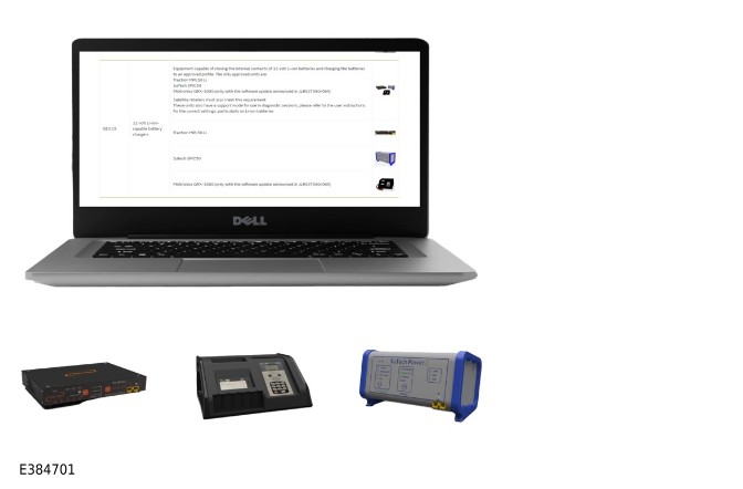
E384701

For information on which battery chargers are JLR approved for 12V Li-ion batteries refer to:

'Tooling and Equipment' catalogue - https://special-tools.JLRext.c...

  • 'Minimum Standards Tools'
  • 'General Equipment'
  • 'GE3.15 Electrical'.

These JLR approved (BSU)s are capable of the following functions:

  • 12V Battery support - Maintains 12V Li-ion battery SOC during work on the vehicle
  • 12V Battery charging (In vehicle) - Increases the 12V Li-ion battery SOC
  • 12V Battery charging (Out of vehicle) - Increases the 12V Li-ion battery SOC
  • 12V Battery circuit recovery - Closes a Level 2 open isolation relay.

For additional information, refer to: Battery Support Procedure - Vehicles With: 12V Li-Ion Startup Battery (414-00 Battery and Charging System - General Information, General Procedures).

DIAGNOSTICS - LEVEL 1 FAULT
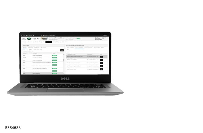
E384688

Using the JLR approved diagnostic equipment, the 'Battery Test' will show if the battery is operating correctly, requires recovery, charging or replacement.

A Level 1 fault will display a warning message on the Instrument Panel Cluster Control Module (IPC).

The isolation relay will remain closed.

A Level 1 fault results from the following:

  • Low voltage - Any cell voltage between 1.8V and 2.0V
  • Low voltage - A battery voltage between 9.0V and 10.0V
  • Over voltage - Any cell voltage between 3.7V and 3.8V
  • High temperature - Any cell temperature between 68°C and 80°C

DIAGNOSTICS - LEVEL 2 FAULT
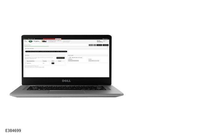
E384699

Because the 12V (Li-Ion) starter battery provides a higher terminal voltage at a lower SOC, the terminal voltage can no longer be used to determine the battery SOC.

If however the terminal voltage reads 0V, this could be the result of an open isolation relay.

If the isolation relay is open, an approved (BSU) must be used to power the vehicle in order to use the JLR approved diagnostic equipment.

A Level 2 fault will open the isolation relay in the SBU.

This level of fault is recoverable.

A Level 2 fault results from the following:

  • Low voltage - Any cell voltage between 0.5V and 1.8V
  • Low voltage - A battery voltage between 6.1V and 9.0V
  • Over voltage - Any cell voltage between 3.8V and 4.0V
  • High temperature - Any cell temperature more than 80°C.
  • Over discharge current for a pre-determined time period.

DIAGNOSTICS - LEVEL 3 FAULT
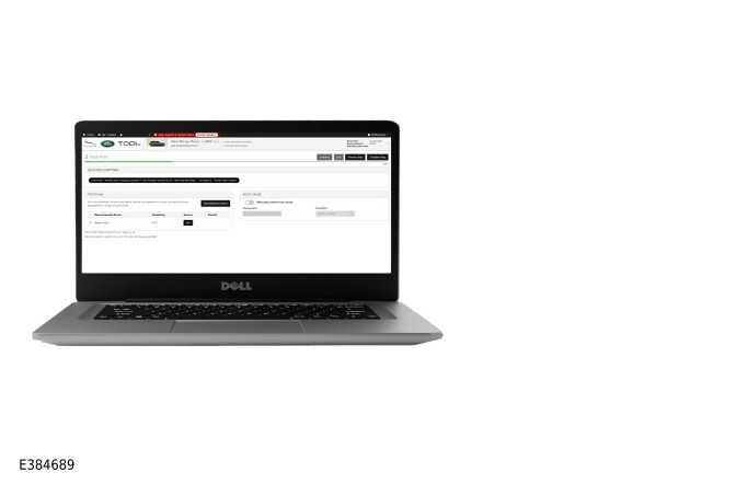
E384689

A Level 3 fault will open the isolation relay in the SBU.

This level of fault is not recoverable.

A Level 3 fault results from the following:

  • Low voltage - Any cell voltage less than 0.5V
  • Low voltage - A battery voltage of less than 6.1V
  • Over voltage - Any cell voltage more than 4.0V
  • Over Voltage - A battery voltage more than 14.2V
  • Over discharge current for a pre-determined time period.

The battery will require replacement.

The battery can only be replaced if diagnosed during the 'Battery Test' application in the JLR approved diagnostic equipment.

Control Diagram

NC11 Mild Hybrid Electric Vehicle (MHEV) - CONTROL DIAGRAM
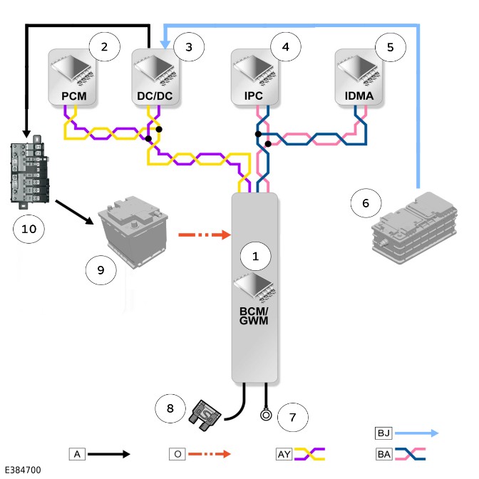
E384700

ItemDescriptionItemDescription
1BCM/GWMALPulse Width Modulated (PWM)
2Powertrain Control Module (PCM)AHardwired
3DC/DCAYPower Mode Zero (PMZ) CAN
4IPCBAHigh Speed (HS) Human Machine Interface (HMI) CAN
5Interactive Display Module 'A' (IDMA)BJ48V Cable
648V battery  
7Ground  
8Power supply  
912V Li-ion battery  
1012V battery junction box  

On vehicles with the NC11 MHEV installed there is no generator.

The 12V battery is charged from the Crank Integrated Motor Generator (CIMG) on the 48V system.

48V Direct Current (DC) is converted to 12V DC by the DC/DC converter.

For additional information, refer to: MHEV Battery (611-01 Battery - V8 T/C 4.4L Petrol, Description and Operation).

With the correct pre-conditions the 48V CIMG is used to start the engine.

At least 95% of all engine starts are likely to be using the CIMG.

When the pre-conditions are not achieved the 12V Li-ion battery and conventional starter motor are used to start the engine.

For additional information, refer to: Starting System (303-06 Starting System - V8 T/C 4.4L Petrol, Description and Operation).

Battery and Charging System - General Information

PHEV Battery Care Requirements (G4709360)

DESCRIPTION AND OPERATION

1. Introduction

1. Introduction

This document defines the requirements for care and maintenance of the Plug-in Hybrid Electric Vehicle (PHEV) battery, and the standard of PHEV battery care at retailers.

In order to prevent damage to the PHEV battery and make sure of a satisfactory service life, all processes detailed within this document must be adhered to.

It is important to note the following key point:

  • Self Discharge: A PHEV battery will slowly discharge due to its own internal chemical processes if it is connected to a vehicle or not.

The PHEV battery can be permanently damaged if the State Of Charge (SOC) becomes too low.

This will occur if the PHEV battery is allowed to discharge below:

  • A reading of 0% SOC as displayed on the .
  • Or 15% State of Charge as read with the >span class="acronym">Jaguar Land Rover (JLR) approved diagnostic equipment.

2. PHEV battery SOC and SoH

Activity-
Initial Battery Reading-
State of Charge-
Average State of Health (Power Fade)-
Average State of Health (Capacity Fade)-
Date-
Signature-
30 Days From Initial Battery Reading-
State of Charge-
Average State of Health (Power Fade)-
Average State of Health (Capacity Fade)-
Date-
Signature-
60 Days From Initial Battery Reading-
State of Charge-
Average State of Health (Power Fade)-
Average State of Health (Capacity Fade)-
Date-
Signature-
90 Days From Initial Battery Reading-
State of Charge-
Average State of Health (Power Fade)-
Average State of Health (Capacity Fade)-
Date-
Signature-
120 Days From Initial Battery Reading-
State of Charge-
Average State of Health (Power Fade)-
Average State of Health (Capacity Fade)-
Date-
Signature-
150 Days From Initial Battery Reading-
State of Charge-
Average State of Health (Power Fade)-
Average State of Health (Capacity Fade)-
Date-
Signature-
Customer Handover-
State of Charge-
Average State of Health (Power Fade)-
Average State of Health (Capacity Fade) 
Date-
Signature-

The PHEV battery SOC and State of Health must be checked every 30 days and re-charged if required.

3. Checking PHEV battery SOC

There are 2 ways to read the SOC value:

  • Read the SOC from the Instrument Panel Cluster Control Module B (IPCB)
  • Read the SOC using the JLR approved diagnostic equipment.

Without JLR approved diagnostic equipment:

When first entering the vehicle, the IPC message center displays the PHEV battery SOC.

NOTE:

The State of Health can only be checked using the JLR approved diagnostic equipment.
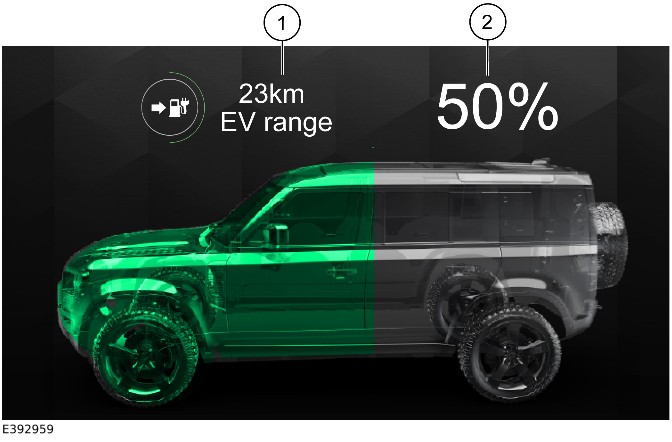
E392959

ItemDescription
1PHEV battery estimated range on IPCB
2PHEV battery SOC on IPCB

With JLR approved diagnostic equipment

The SOC can only be checked with the PHEV battery installed in the vehicle.

With JLR approved diagnostic equipment:

  • Connect the JLR approved battery support unit.
  • Connect the JLR approved diagnostic equipment to the vehicle and begin a new session.
  • Follow the JLR approved diagnostic equipment prompts.
  • Select 'Diagnostics'.
  • Select 'Data Logger' - Battery Energy Control Module (BECM) - Data IDentifier (DID) 4801 - Hybrid Battery SOC.
  • Select 'Start' and read the SOC value.
  • If required, reset the vehicle to 'Transit mode'.
  • When all of the tasks are complete, exit the session.
  • Disconnect the JLR approved diagnostic equipment and the JLR approved battery support unit.

Test results

Test ResultsAction
SOC less than 15>#/td###Re-charge to 25>#/td###
SOC less than 30% and has discharged more than 5% since last checkRe-charge to 25>#/td###
SOC more than 60% (Only applicable for storage or transport)Discharge to 25>#/td###

4. Checking the PHEV battery (SOH)

E392937

The State of Health can only be checked with the PHEV battery installed in the vehicle.

  • Connect the JLR approved battery support unit.
  • Connect the JLR approved diagnostic equipment to the vehicle and begin a new session.
  • Follow the JLR approved diagnostic equipment prompts.
  • Select 'Diagnostics'.
  • Select BECM
  • Select 'Module' in 'Applications and Troubleshooting'
  • Select BECM then run the application - Hybrid/Electric Vehicle (EV) Battery State of Health Overview - PHEV.
  • Read the values for Hybrid/EV Battery Average State Of Health (Power Fade) and Hybrid/EV Battery Average State Of Health (Capacity Fade).
  • Alternatively, select 'Data Logger' - BECM - DIDs 4915 - Hybrid/EV Battery Average State Of Health (Power Fade) and DIDs 4918 - Hybrid/EV Battery Average State Of Health (Capacity Fade).
  • If required, reset the vehicle to 'Transit mode'.
  • When all of the tasks are complete, exit the session.
  • Disconnect the JLR approved diagnostic equipment and the JLR approved battery support unit.

Capacity Fade, Power Fade and SOC

TermWhat is measuredImpactAnalogy
Capacity FadeLoss of ability to store energyReduced rangeShrinking fuel tank
Power FadeLoss in the rate of power deliverySlower acceleration. Reduced regenerationReduced delivery from a fuel pump
SOCRemaining charge levelDetermines the remaining rangeRemaining fuel level

5. Battery charging

CAUTIONS:

  • When using a charging cable, always make sure that the charging cable is fully unwound. Failure to fully unwind the charging cable could lead to overheating of the cable.
  • Always connect the charging cable to the electricity supply before connecting to the vehicle.

NOTE:

After pressing the release switch there may be a 2 second delay before you are able to release the charge cable from the vehicle.
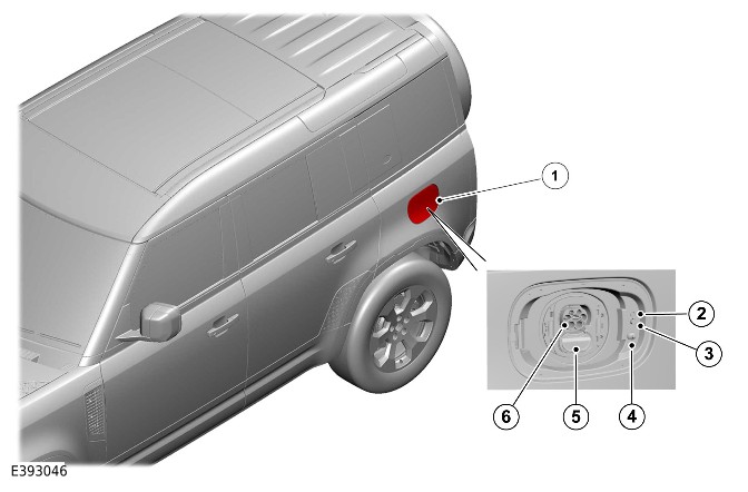
E393046

ItemDescription
1Charge port outer flap
2Charge indicator
3Charge cable release switch
4Push - push latch
550KW Direct Current (DC) charge port connector cover
67KW Alternating Current (AC) charge port connector

The PHEV battery must be charged following the applicable vehicle charging procedure using a charging cable:

  • Open the outer and inner charge port flap and open the cap.
  • Always connect the charging cable to the electricity supply before connecting to the vehicle.
  • Plug in the connector to the electricity supply/wall box.
  • Connect the charging cable to the charging port.

Recharge until the PHEV battery is 25% charged.

If a charging infrastructure is unavailable:

  • With the vehicle in Power Mode 7 (engine running) and in PARK (P) or NEUTRAL (N), the PHEV battery will charge. There is no requirement to increase the engine speed.
  • Recharge until the PHEV battery is 25% charged.

6. Charge gauge in IPCB
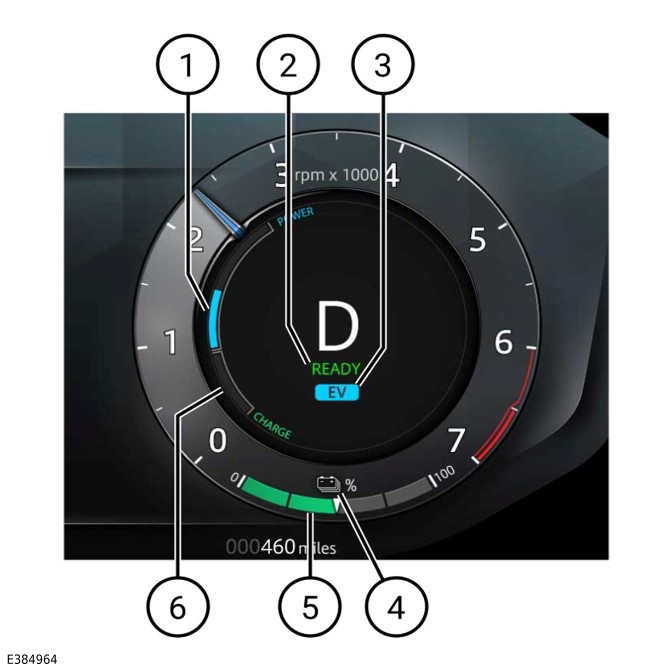
E384964

ItemDescription
1Power usage
2Ready light
3EV Mode indicator
4PHEV battery SOC icon
5PHEV battery SOC gauge in 25% increments
6Regenerated electrical energy

If the vehicle is driven the CHARGE zone (6) indicates the amount of the regenerated energy when the vehicle is decelerating during braking or overrun.

The PHEV battery gauge (5) displays the SOC.


Startup Battery and Cables - INGENIUM I6 3.0L Petrol/INGENIUM I6 3.0L Diesel (G2342547)

DESCRIPTION AND OPERATION

COMPONENT LOCATION

Component Location - 1 of 1

NOTE:

Vehicle with 5 doors is shown, vehicle with 3 doors is similar.
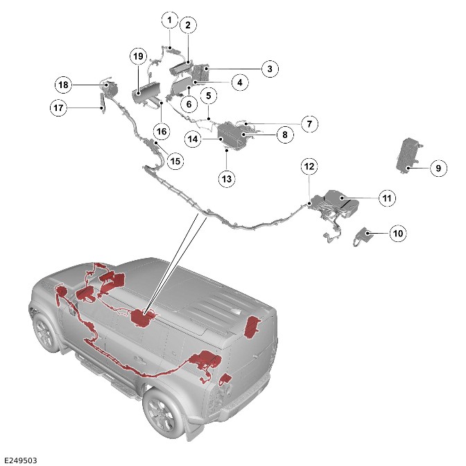
E249503

ItemDescription
1Jump start terminal for the jump start (positive) connection
2Engine Junction Box (EJB)
3Passenger Junction Box (PJB)
4Body Control Module/Gateway Module (BCM/GWM)
5Startup battery cable - Battery Junction Box (BJB) to the jump start (positive) terminal
6Touch Screen (FCDIM)
7BJB
8Battery Monitoring System (BMS) control module
9Rear Junction Box (BCMB)
10Auxiliary Junction Box (AJB)
11Direct Current to Direct Current converter (DC/DC)
12Mild Hybrid Electric Vehicle (MHEV) battery junction box - Rear
13Ground cable
14Startup battery
15MHEV battery junction box - Front
16Starter motor
17Powertrain Control Module (PCM)
18Belt Integrated Starter Generator (BISG)
19Instrument Panel Cluster (IPC)

OVERVIEW

CAUTION:

When connecting a slave startup battery to the vehicle, always use the vehicle body ground terminal in the engine compartment. Never connect directly to the startup battery ground terminal, because the BMS control module can be damaged.

NOTE:

The fusible links are installed behind a removable cover.

The startup battery supplies electrical power to the BJB. The BJB connects to the following components:

  • Starter motor
    • For additional information, refer to: Starting System (303-06 Starting System - INGENIUM I6 3.0L Petrol, Description and Operation).
  • DC/DC
    • For additional information, refer to: Direct Current to Direct Current Converter (414-03A Battery Charging - INGENIUM I6 3.0L Petrol/INGENIUM I6 3.0L Diesel, Vehicles With: MHEV, Description and Operation).
  • Jump start terminal - positive.

The DC/DC supplies the power for normal operation of the 12V systems only in Power Mode 7 (engine running).

The BJB supplies power to the following:

  • EJB
  • AJB
  • PJB
  • BCMB.

The BMS control module is installed on the startup battery negative terminal. The BMS control module is connected to the vehicle body ground by a ground cable installed on the BMS control module. The BMS control module sends startup battery data to the Body Control Module (BCM)/Gateway Control Module (GWM). When you install a new startup battery on the vehicle, you must calibrate the BMS control module with the Jaguar Land Rover (JLR) approved diagnostic equipment.

The BCM/GWM is the main controller of the vehicle body systems. The BCM/GWM contains the whole charging system software required to control the startup battery charging system and components. The BCM/GWM monitors the components and stores the related Diagnostic Trouble Code(s) (DTC)s.

The DC/DC provides electrical power to support the 12V in Power Mode 7 (engine running) in MHEV vehicle. The output voltage of the DC/DC is controlled by the BCM/GWM. The DC/DC operating mode is controlled by:

  • Vehicle Supervisory Controller (VSC) or
  • PCM.

For additional information, refer to: Direct Current to Direct Current Converter (414-03A Battery Charging - INGENIUM I6 3.0L Petrol/INGENIUM I6 3.0L Diesel, Vehicles With: MHEV, Description and Operation).

The BJB, EJB, PJB, BCMB and AJB contain fuses and relays to distribute electrical power to various vehicle systems. The junction box contains the megafuses.

  • The BJB is installed under the driver seat, beside the startup battery.
  • The EJB is installed in the engine compartment.
  • The PJB is installed on the passengers side behind the glovebox and next to the BCM/GWM.
  • The BCMB is located on the right of the loadspace and behind the trim panel.
  • The AJB is installed under the loadspace compartment floor.

The single jump start terminal is located adjacent to the right top mount in the engine compartment. A cover protects the positive terminal when not in use. When you have to jump start the vehicle, remove the cover and attach the positive jump lead to the terminal. When the positive terminal is not in use, install the cover.

Transit Mode

All new vehicles are delivered from the factory in transit mode. Transit mode replaces the traditional transit relay and inhibits some electrical systems and features to eliminate quiescent drain from the startup battery during delivery. Transit mode also inhibits some electrical loads when in Power Mode 7 (engine running). Transit mode makes sure that the startup battery is never discharged while in Power Mode 7 (engine running).

To remove the vehicle from transit mode, use the JLR approved diagnostic equipment.

For additional information, refer to: Preliminary - Non OCTA Vehicle (101-01 Pre-Delivery Inspection Manual, Description and Operation).

Power Modes

The BCM/GWM controls the power supplies for the various vehicle functions. There are 9 Power Modes available which are used by various systems to determine the operating condition of the vehicle.

Only 5 of these modes are noticeable to the driver and technicians as follows:

  • Power Mode 0 - ignition OFF.
  • Power Mode 4 - Accessory (vehicle unlocked and Smart Key present).
  • Power Mode 6 - Ignition ON.
  • Power Mode 7 - Engine running.
  • Power Mode 9 - Engine cranking.

DESCRIPTION

Startup Battery

NOTE:

Vehicle with 5 doors is shown, vehicle with 3 doors is similar.
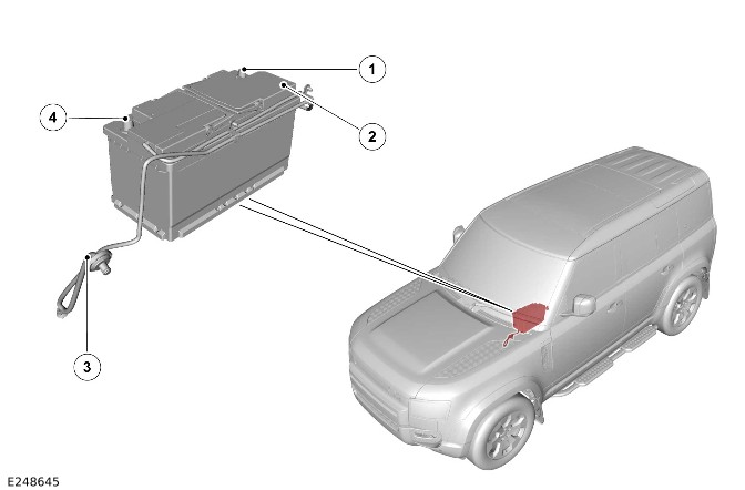
E248645

ItemDescription
1Startup battery negative terminal
2Startup battery
3Startup battery breather pipe
4Startup battery positive terminal

The startup battery is located in a tray under the driver seat. The startup battery is secured in position with a clamp plate and a bolt assembly.

The startup battery is an H8 90 Ah, 850 CCA Absorbed Glass Mat (AGM) battery on all vehicles.

The startup battery negative terminal has the BMS control module located on it. The startup battery positive terminal connector contains the megafuse and connects to the BJB.

Battery Monitoring System Control Module
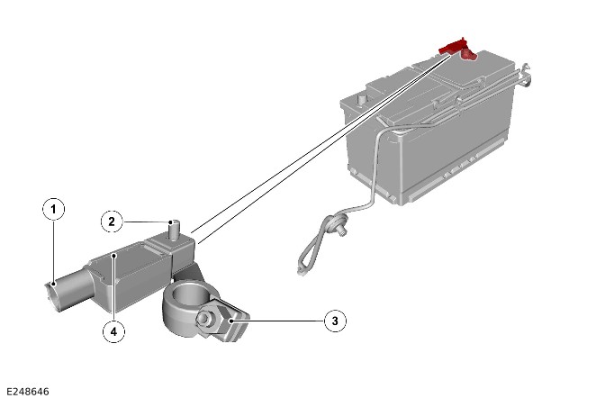
E248646

ItemDescription
1BMS control module startup battery negative terminal clamp
2BMS control module
3Wiring harness connector
4BMS control module terminal for the BMS plate

The BMS control module is located on the startup battery negative terminal. The BMS control module is clamped to the startup battery negative terminal with a bolt and nut. The BMS control module has a ground terminal for the ground cable connection secured with a nut.

The ground cable connects to a vehicle body ground connection.

The BMS control module has a single 2-pin connector to the wiring harness. The 2-pin connector has the following electrical connections:

  • Positive startup battery feed directly from the startup battery positive terminal.
  • Local Interconnect Network (LIN) hardwired to the BCM/GWM.

The BCM/GWM controls the startup battery current drain and State of Charge. The BMS control module measures the startup battery current and voltage, which it communicates to the BCM/GWM on the LIN. The BCM/GWM transmits the startup battery information over the Controller Area Network (CAN) systems buses to other vehicle systems. Based on the information received from the BMS control module, the BCM/GWM controls the output from the DC/DC. The BCM/GWM requests that specific modules are switched OFF to decrease electrical loads when necessary.

The BMS control module contains software maps that provide a mathematical model of startup battery conditions. The BMS control module constantly receives information from the BCM/GWM regarding the vehicle state and electrical loading.

When you install a new startup battery on the vehicle, you must calibrate the BMS control module with the JLR approved diagnostic equipment.

CAUTION:

  • Always make sure the battery clamps are installed correctly as this can cause miscalculations by the BMS.
  • Due to the self-calibration routine, it is a must that all power supply diagnostic testing is done using the JLR approved diagnostic equipment.

When an error occurs, the BMS control module sends a message to the BCM/GWM through the LIN. The DTC is stored in the BCM/GWM. The DTC is read using the JLR approved diagnostic equipment.

The JLR approved diagnostic equipment has a process for an automated power supply diagnostic procedure. The procedure provides a menu driven process to locate a fault in a logical sequence. The procedure uses the capability of the BMS control module and the LIN of generator controlled functions to provide current flow information. The procedure uses the controlled functions of the following, to provide current flow information:

  • BMS control module through the LIN.
  • DC/DC through the High Speed (HS) CAN power mode zero systems bus.

For additional information, refer to: MHEV Battery and Cables - Non OCTA Vehicle (414-01B Battery, Mounting and Cables - MHEV, Description and Operation).

BCM/GWM

NOTE:

Right Hand Drive (RHD) vehicle is shown, Left Hand Drive (LHD) vehicle is similar.
E255368

The BCM/GWM is attached to a bracket and bolted to the passenger side of the cross-car beam, behind the glovebox.

The BCM/GWM is located adjacent to the PJB, and it is the main controller of the vehicle body systems.

The BCM/GWM contains software to control the following functions:

  • Determine the condition of the startup battery.
  • DC/DC output:
    • Control the DC/DC output to reach a desired system voltage.
    • Control the DC/DC output to reach a target startup battery State of Charge.
  • Load management:
    • Load management controls the 12V power system to make sure that the system is not overloaded. In certain events, for example, during engine stop/start, some systems can be switched OFF.
  • Control stop/start system functionality:
    • The BCM/GWM can only inhibit stop/start functionality depending on the power system condition.
    • The BCM/GWM also provides supporting functionality through load management.

The BCM/GWM communicates with other system control modules on the following:

  • FlexRay
  • HS CAN powertrain systems bus
  • HS CAN power mode zero systems bus
  • HS CAN Underbody (UN) systems bus
  • HS CAN Human Machine Interface (HMI) systems bus
  • HS CAN body systems bus.

The BCM/GWM communicates with the BMS control module through a LIN.

Startup Battery Cables

NOTE:

Vehicle with 5 doors is shown, vehicle with 3 doors is similar.
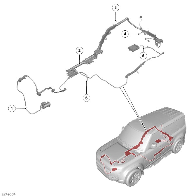
E249504

ItemDescription
1Startup battery cable (positive) from the jump start terminal (positive) to the starter motor
2Main wiring harness
3Ground cable from the BCMB to the vehicle engine ground connection
4Ground cable from the AJB to a vehicle body ground connection
5Ground cable from the DC/DC to a vehicle body ground connection
6Ground cable from the BMS plate to the vehicle engine ground connection

The startup battery cables (positive) are for the high current connections between the following:

  • Startup battery
  • DC/DC
  • Starter motor
  • BJB
  • EJB
  • AJB
  • PJB
  • BCMB.

The startup battery cables (positive) from the BJB to the other junction boxes and modules are all in the main wiring harness.

OPERATION

The startup battery State of Charge is monitored by the BCM/GWM with the BMS control module. In Power Mode 7 (engine running) the startup battery State of Charge is maintained by the DC/DC. The BCM/GWM communicates with the DC/DC through the HS CAN power mode zero systems bus.

For additional information, refer to: Direct Current to Direct Current Converter (414-03A Battery Charging - INGENIUM I6 3.0L Petrol/INGENIUM I6 3.0L Diesel, Vehicles With: MHEV, Description and Operation).

The power from the startup battery and the DC/DC is distributed to all the vehicle 12V systems from the BJB.

Battery Monitoring System

The BMS control module monitors the condition of the startup battery in all Power Modes.

The BMS control module sends the startup battery State of Charge to the BCM/GWM on a LIN. When the startup battery State of Charge is less than a set threshold from the critical start point, the BMS control module sends a message. The warning message is transmitted to the BCM/GWM.

The BMS control module determines that the control modules are still active when the startup battery State of Charge continuously decreased to less than 50%. When this occurs, the BMS control module sends a shutdown message on the LIN to the BCM/GWM. The BCM/GWM then transmits a shutdown message on the CAN systems buses to all control modules, requesting them to shut down.

When in Power Mode 0 (ignition OFF), the BMS control module monitors the startup battery State of Charge for a further 15 minutes. The BMS control module determines when the startup battery State of Charge is still dropping due to the quiescent drain current. The BMS control module sends a power disconnect signal to the BCM/GWM on the LIN. The BCM/GWM then sends a signal to the PJB on the hardwired connections to open its internal relays. When the PJB relays are open, the power supply from the startup battery to non-critical control modules is removed. The non-critical control modules are any modules associated with the infotainment system and also the climate control system.

The use of the LIN communication makes sure that no other control modules 'wake' during this process. When CAN systems bus communication was used, all modules on the CAN systems bus would be woken by the message.

Battery Monitoring System Control Module Low Battery Warning and Energy Management Messages

The BMS control module continuously monitors the condition of the startup battery. When excessive startup battery discharge occurs, the system begins to shut down non-essential electrical systems in order to protect the startup battery.

The BMS control module displays warning messages to inform the driver:

  • The startup battery is at a low level of charge.
  • Power consumption limit has been exceeded in Power Mode 0 (ignition OFF).
Display screenMessage
FCDIM'Energy Management'
IPCLow Battery - 'Please start engine'

'Energy Management'

The message is displayed as a warning on the FCDIM when in Power Mode 6 (ignition ON) or less. The message indicates that the startup battery State of Charge is less than a predefined threshold. The message displays until the startup battery State of Charge is greater than the predefined threshold. The Power Mode 7 (engine running) must be for a minimum of 10 minutes.

Low Battery - 'Please start engine'

The message is displayed on the IPC message center when in Power Mode 6 (ignition ON) or less. The message indicates that the startup battery State of Charge is less than a predefined threshold. As soon as the startup battery State of Charge is greater than this threshold, the message is removed. The message can be manually removed by pressing the 'Menu/OK' switch on the left Steering Wheel Switch (SWS).

The messages are based on a percentage of the startup battery capacity. The percentage can change based upon several factors. The messages reset after the vehicle is driven for 10 minutes in Power Mode 7 (engine running). The time allows the startup battery to replace any lost charge. However, when in Power Mode 7 (engine running) for less than 10 minutes, the messages are displayed after an additional 5 minutes.

The messages are available for the driver to use the vehicle systems within Power Mode 0 (ignition OFF). The messages only occur when in Power Mode 6 (ignition ON).

Battery Monitoring System Control Module Self Calibration

The BMS control module periodically initiates a self-calibration routine. The self calibration requires that the startup battery is fully charged.

To self-calibrate, the BMS control module sends a signal to the BCM/GWM.

NOTE:

When the vehicle is only driven for short periods the charging process could take a number of days to complete.

When the startup battery is fully charged, the system then resumes normal charging control. The optimum level of charge is between 12.3V to 15.2V, depending on startup battery condition, temperature and loading.

The BMS control module also monitors the startup battery condition within Power Mode 0 (ignition OFF). When a low voltage condition is detected, the BMS control module can request the infotainment system is switched OFF to protect startup battery voltage.

Electrical Load Management

The BCM/GWM contains the electrical load management. The BCM/GWM monitors the vehicle system power loads in all Power Modes.

Engine Stop/Start Operation with The Starter Motor

For additional information, refer to: Belt Intergrated Starter Generator (414-03 Battery Charging - INGENIUM I6 3.0L Petrol, [+] MHEV, Description and Operation).

When the engine is stopped, the BCM/GWM continues to monitor the startup battery State of Charge. When the startup battery voltage is less than 11.2V, the BCM/GWM initiates an engine start. A startup battery voltage of less than 11.2V, results in degraded starting performance or possible startup battery damage.

Diagnostics

The BCM/GWM records any DTCs and related data. Read the DTCs and related data with the JLR approved diagnostic equipment.

The JLR approved diagnostic equipment can read live data and activate certain components.

CONTROL DIAGRAM

Control Diagram - 1 Of 1
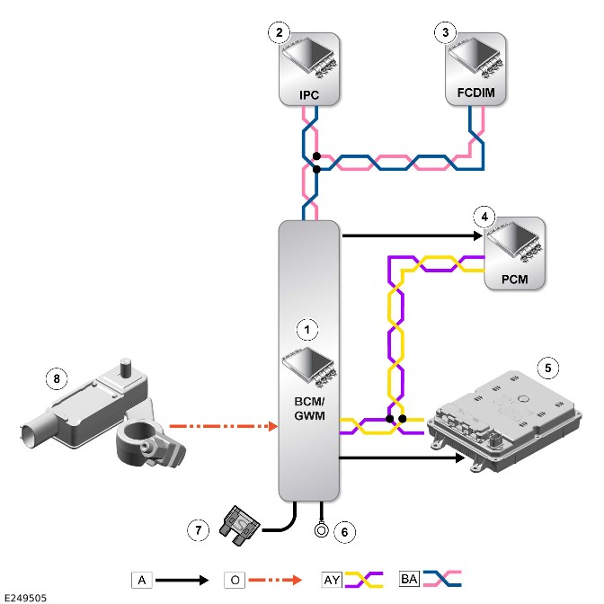
E249505

A = HARDWIRED: O = LIN: AY = HS CAN POWER MODE ZERO SYSTEMS BUS: BA = HS CAN HMI systems bus.

ItemDescription
1BCM/GWM
2IPC
3FCDIM
4PCM
5DC/DC
6Ground
7Power supply
8BMS control module

MHEV Battery and Cables - Non OCTA Vehicle (G2342548)

DESCRIPTION AND OPERATION

COMPONENT LOCATION

Component Location - 1 of 1

NOTE:

Vehicle with 5 doors is shown, vehicle with 3 doors is similar.
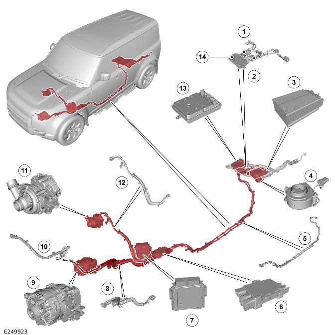
E249923

ItemDescription
1Mild Hybrid Electric Vehicle (MHEV) cables - Rear MHEV junction box to Direct Current to Direct Current (DC/DC) converter
2MHEV cables - Rear MHEV junction box to MHEV battery
3MHEV battery
4MHEV battery electric cooling fan
5MHEV cables - Front MHEV junction box to rear MHEV junction box
6MHEV junction box - Front
7Powertrain Control Module (PCM)
8MHEV cables - Front MHEV junction box to Belt Integrated Starter Generator (BISG)
9BISG
10MHEV cables - BISG
11Electric supercharger
12MHEV cables - Front MHEV junction box to electric supercharger
13DC/DC converter
14MHEV junction box - Rear

OVERVIEW

The MHEV battery has 5 primary functions:

  • Provide all the electrical power for the 12V systems through the DC/DC converter.
    • For additional information, refer to: Direct Current to Direct Current Converter (414-03A Battery Charging - INGENIUM I6 3.0L Petrol/INGENIUM I6 3.0L Diesel, Vehicles With: MHEV, Description and Operation).
    • For additional information, refer to: Startup Battery and Cables - INGENIUM I6 3.0L Petrol/INGENIUM I6 3.0L Diesel (414-01B Battery, Mounting and Cables - MHEV, Description and Operation).
  • Store the electrical energy from the BISG. The BISG generates electrical energy from recovered energy when the engine overruns and from engine torque.
    • For additional information, refer to: Belt Integrated Starter Generator (414-03A Battery Charging - INGENIUM I6 3.0L Petrol/INGENIUM I6 3.0L Diesel, Vehicles With: MHEV, Description and Operation).
  • Provide the power for the BISG when it provides torque for the engine assist.
    • For additional information, refer to: Belt Integrated Starter Generator (414-03A Battery Charging - INGENIUM I6 3.0L Petrol/INGENIUM I6 3.0L Diesel, Vehicles With: MHEV, Description and Operation).
  • Provide power to the BISG for engine start when auto stop/start is in operation.
    • For additional information, refer to: Starting System (303-06 Starting System - INGENIUM I6 3.0L Petrol, Description and Operation).
  • Provide the power for the electric supercharger.
    • For additional information, refer to: Supercharger Cooling - INGENIUM I6 3.0L Petrol AJ20 (303-03 Supercharger Cooling - INGENIUM I6 3.0L Petrol, Description and Operation).

The MHEV cables distribute the electrical energy to the MHEV battery system components.

DESCRIPTION

MHEV Battery Housing

CAUTION:

Make sure that the air inlet behind the second row seats is not obstructed. A reduction in the cooling airflow can cause overheating in the following components:

  • The MHEV battery
  • The DC/DC converter.

E249924

ItemDescription
1MHEV battery
2MHEV battery breather pipe
3MHEV battery electric cooling fan
4MHEV battery housing
5Cradle

The battery housing is a metal cowl which surrounds the MHEV battery. The MHEV battery cooling fan blows air into the housing. The air is directed over the surface of the MHEV battery and absorbs heat from the battery surface. The air is expelled at the rear of the housing.

MHEV Battery

NOTE:

The MHEV battery is connected to ground through the MHEV junction box (rear).
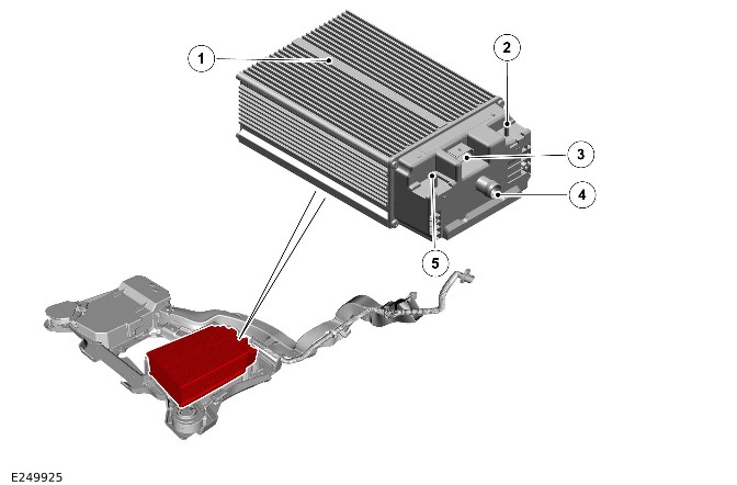
E249925

ItemDescription
1MHEV battery
2MHEV cable terminal (positive)
3Wiring harness connector
4MHEV battery breather pipe connection
5MHEV cable terminal (negative)

The MHEV battery is located in the loadspace under the floor, adjacent to the DC/DC converter. The MHEV battery is installed in the MHEV battery housing with bolts.

The MHEV battery is a sealed unit and cannot be opened. The MHEV battery contains the following:

  • MHEV battery module with 14 cells.
  • The Battery Energy Control Module (BECM).

The cells in the MHEV battery module are the Lithium-ion type.

The BECM controls the electrical current flowing into and out of the MHEV battery.

The MHEV battery has the following connections:

  • The MHEV cable terminal (positive).
  • The MHEV cable terminal (negative).
  • A wiring harness connector for the BECM.
  • A MHEV battery breather pipe connection allows for pressure equalization between the inside of the MHEV battery and the outside atmosphere. A MHEV battery breather pipe also allows gases to be vented outside the passenger compartment.

The MHEV battery is cooled by an air flow produced the MHEV battery electric cooling fan. The MHEV battery electric cooling fan is powered by a 12V Direct Current (DC) motor which is controlled by a Pulse Width Modulated (PWM) signal from the BECM.

MHEV Battery Electric Cooling Fan

CAUTION:

Make sure that the air inlet behind the second row seats is not obstructed. A reduction in the cooling airflow can cause overheating in the following components:

  • The MHEV battery
  • The DC/DC converter.

E249926

ItemDescription
1Wiring harness connector
2Cooling air inlet
3Cooling air outlet

The MHEV battery electric cooling fan is adjacent to the MHEV battery housing. The MHEV battery electric cooling fan housing is attached to the cradle with 2 bolts.

The cooling fan outlet connects with the MHEV battery housing. Cool air is directed into the housing where it passes over the outside of the MHEV battery in order to absorb heat.

The MHEV battery electric cooling fan has a short fly lead with a 4-pin wiring harness connector. The 4-pin connector only uses 3 pins of the wiring harness connector for the following electrical connections:

  • Power supply from the Passenger Junction Box (PJB).
  • A PWM signal from the BECM in the MHEV battery.
  • A ground connection.

The BECM in the MHEV battery sends a PWM signal to the MHEV battery electric cooling fan. The BECM controls the speed of the MHEV battery electric cooling fan. The MHEV battery electric cooling fan then regulates its speed depending on the duty cycle of the PWM signal.

Cooling Air Flow
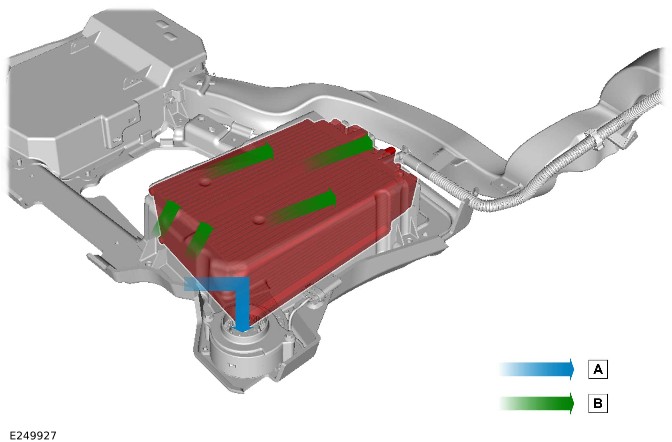
E249927

ItemDescription
ACooling air inlet
BCooling air outlet

MHEV junction box - Front

E249928

ItemDescription
1MHEV cable - To rear MHEV junction box connector
2MHEV cable - To rear MHEV junction box connector
3MHEV cable - To BISG
4MHEV cable - To BISG
5MHEV cable - To electric supercharger

The front MHEV junction box is located under the floorpan on the left. The front MHEV junction box is attached to the floorpan with 3 bolts.

The front MHEV junction box has 2 MHEV cable connections from the following:

  • BISG
  • Electric supercharger.

The main cable runs from the BISG to the rear MHEV junction box are connected by non fused bus bars. The connection to the electric supercharger incorporates a non serviceable 100A fuse.

MHEV junction box - Rear
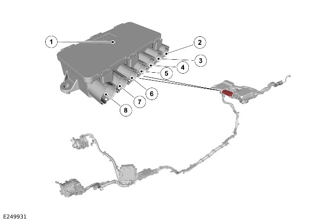
E249931

ItemDescription
1MHEV junction box - Rear
2MHEV cable - To MHEV battery - Positive
3MHEV cable - To DC/DC converter
4MHEV cable - To DC/DC converter
5MHEV cable - Ground
6MHEV cable - To MHEV battery - Negative
7MHEV cable - To rear MHEV junction box connector
8MHEV cable - To rear MHEV junction box connector

The rear MHEV junction box is located in the cradle between the DC/DC converter housing and the MHEV battery housing. The rear MHEV junction box is secured to the cradle by 2 bolts.

There is a connection from the MHEV battery 48V negative terminal to the DC/DC converter, body ground and the front MHEV junction box. The rear MHEV junction box has a 100A fuse on the 48V positive terminal to the DC/DC converter.

The rear MHEV junction box has a 200A fuse on the 48V positive terminal to the MHEV battery.

The 48V negative cables to the DC/DC converter, BISG, and electric supercharger provide a high current return circuit.

MHEV cables
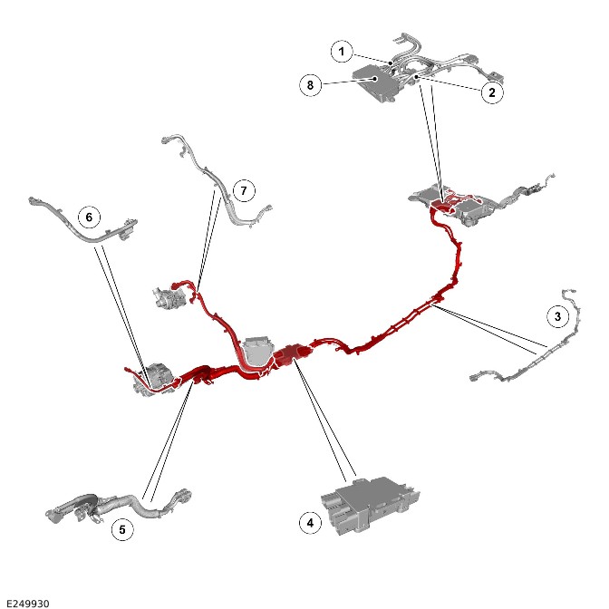
E249930

ItemDescription
1MHEV cables - Rear MHEV junction box to the DC/DC converter
2MHEV cables - Rear MHEV junction box to the MHEV battery
3MHEV cables - Rear MHEV junction box to the front MHEV junction box
4MHEV junction box - Front
5MHEV cables - Front MHEV junction box to the BISG
6MHEV cables - BISG
7MHEV cables - Front MHEV junction box to the Electric supercharger
8MHEV junction box - Rear

The MHEV cables have a pale blue outer covering. The MHEV cables connect the following components:

  • MHEV battery
  • MHEV junction box - Front
  • MHEV junction box - Rear
  • DC/DC converter
  • BISG
  • Electric supercharger.

The MHEV cables distribute the MHEV battery voltage of approximately 48V to the MHEV battery components.

MHEV cables Electromagnetic Compatibility Insulation
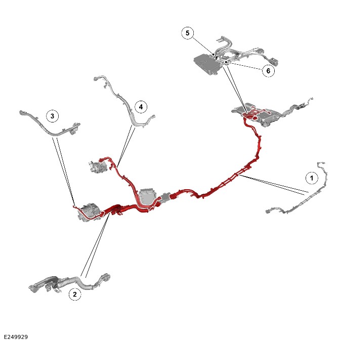
E249929

ItemDescription
1MHEV cable - Front MHEV junction box to the rear MHEV junction box
2MHEV cable - Front MHEV junction box to the BISG
3MHEV cable - BISG
4MHEV cable - Front MHEV junction box to the electric supercharger
5MHEV cable - Rear MHEV junction box to the MHEV battery and the DC/DC converter
6MHEV cable - Rear MHEV junction box to the MHEV battery

There are 5 sections of the MHEV cables that have Electromagnetic Compatibility (EMC) screening on them as following:

  • The front MHEV junction box to the rear MHEV junction box
  • The front MHEV junction box to the BISG
  • The MHEV cables - BISG
  • The front MHEV junction box to the electric supercharger
  • The rear MHEV junction box to the MHEV battery and the DC/DC converter.

Each section of EMC screening on the MHEV cables has an electrical wiring connector to provide a ground connection. The EMC screening ground connections are installed to the body with bolts.

OPERATION

The MHEV battery is controlled by the PCM through the integrated BECM which is incorporated into the MHEV battery. The PCM communicates with the BECM through the High Speed (HS) Controller Area Network (CAN) power mode zero systems bus. The BECM transmits the MHEV battery State of Charge to the PCM.

When there is a fault with the MHEV battery system the PCM sends a message to the to do the following:

  • Display the red battery warning indicator in the IPC.
  • Display any related warning messages in the IPC message center.

Battery Energy Control Module

The BECM monitors the following to make sure that the MHEV battery operates within normal operational limits:

  • MHEV battery module internal temperature
  • MHEV battery module voltage.

The BECM has the following wiring harness connections:

  • Power supply from the >span class="acronym">Body Control Module B (BCMB).
  • HS CAN power mode zero systems bus (quantity 2).
  • Power Mode 6 (ignition ON) signal from the Body Control Module/Gateway Module (BCM/GWM).
  • PWM signal to the MHEV battery electric cooling fan.

The BECM communicates with the PCM through the HS CAN power mode zero systems bus. The PCM controls the BISG to charge the MHEV battery when electrical energy is required.

For additional information, refer to: Belt Integrated Starter Generator (414-03A Battery Charging - INGENIUM I6 3.0L Petrol/INGENIUM I6 3.0L Diesel, Vehicles With: MHEV, Description and Operation).

The BECM also controls the power available from the MHEV battery for the following:

  • BISG for auto stop/start engine starts and engine assist to increase fuel economy.
    • For additional information, refer to: Belt Integrated Starter Generator (414-03A Battery Charging - INGENIUM I6 3.0L Petrol/INGENIUM I6 3.0L Diesel, Vehicles With: MHEV, Description and Operation).
  • DC/DC converter.
    • For additional information, refer to: Direct Current to Direct Current Converter (414-03A Battery Charging - INGENIUM I6 3.0L Petrol/INGENIUM I6 3.0L Diesel, Vehicles With: MHEV, Description and Operation).
  • Electric supercharger.
    • For additional information, refer to: Supercharger Cooling - INGENIUM I6 3.0L Petrol AJ20 (303-03 Supercharger Cooling - INGENIUM I6 3.0L Petrol, Description and Operation).

The BECM contains a relay. The relay isolates the MHEV battery from the MHEV battery system, without having to remove any MHEV cables.

The BECM controls the MHEV battery electric cooling fan with a PWM signal. The duty cycle of the PWM is used to request the required cooling from the MHEV battery electric cooling fan.

MHEV Battery Charging

The MHEV battery is charged by the BISG with energy from the following sources:

  • Recovered energy when the engine overruns.
    • This uses energy derived from deceleration when the accelerator is released. The crankshaft is being driven by the transmission as the vehicle slows down. The BISG recovers the energy that would otherwise be lost and fully charges the MHEV battery.
  • Engine torque
    • On extended motorway journeys there may be limited opportunities to recover energy during deceleration. In these circumstances energy is taken from the engine when the vehicle is cruising to maintain a minimal battery State of Charge.

The PCM monitors the MHEV battery State of Charge. The PCM determines when is the most efficient time to charge the MHEV battery. The PCM only charges the MHEV battery to a specific State of Charge with engine torque. The MHEV battery can be charged to the maximum State of Charge with the recovered energy when the engine overruns. The recovered energy can then be used by the BISG to provide engine assist when required.

MHEV Battery Stored Energy Usage

The electrical energy produced by the BISG is stored in the MHEV battery and is used by the following:

  • The BISG for the engine auto stop/start operation.
    • For additional information, refer to: Belt Integrated Starter Generator (414-03A Battery Charging - INGENIUM I6 3.0L Petrol/INGENIUM I6 3.0L Diesel, Vehicles With: MHEV, Description and Operation).
  • The BISG to provide engine assist when requested by the PCM, to reduce fuel consumption and exhaust emissions.
  • The DC/DC converter to supply the 12V systems and to charge the startup battery. The DC/DC converter is controlled by the BCM/GWM.
    • For additional information, refer to: Direct Current to Direct Current Converter (414-03A Battery Charging - INGENIUM I6 3.0L Petrol/INGENIUM I6 3.0L Diesel, Vehicles With: MHEV, Description and Operation).
    • For additional information, refer to: Startup Battery and Cables - INGENIUM I6 3.0L Petrol/INGENIUM I6 3.0L Diesel (414-01B Battery, Mounting and Cables - MHEV, Description and Operation).
  • The electric supercharger to supply air to the turbocharger. The electric supercharger is controlled by the PCM.
    • For additional information, refer to: Supercharger Cooling - INGENIUM I6 3.0L Petrol AJ20 (303-03 Supercharger Cooling - INGENIUM I6 3.0L Petrol, Description and Operation).

When the MHEV battery State of Charge is less than a specific limit, the auto stop/start is disabled. The auto stop/start disabled warning indicator is also shown in the IPC.

For additional information, refer to: Belt Integrated Starter Generator (414-03A Battery Charging - INGENIUM I6 3.0L Petrol/INGENIUM I6 3.0L Diesel, Vehicles With: MHEV, Description and Operation).

If the internal temperature of the MHEV battery is outside specific limits, the BECM will restrict the amount of energy which is available.

MHEV Battery Cooling

CAUTION:

Make sure that the air inlet behind the second row seats is not obstructed. A reduction in the cooling airflow can cause overheating in the following components:

  • The MHEV battery
  • The DC/DC converter.

The MHEV battery is air cooled to regulate the internal MHEV battery module temperature. The BECM controls the MHEV battery internal temperature by the operation of the MHEV battery electric cooling fan. The BECM monitors the internal temperature of the MHEV battery. If the BECM determines that cooling is required it sends a PWM signal to operate the MHEV battery cooling fan at an applicable speed.

Diagnostics

The PCM records any Diagnostic Trouble Codes (DTC)and related data. Read the DTCs and related data with the Jaguar Land Rover (JLR) approved diagnostic equipment.

The JLR approved diagnostic equipment enables certain components to be activated and also live data to be read.

CONTROL DIAGRAMS

Control Diagram - 1 of 2
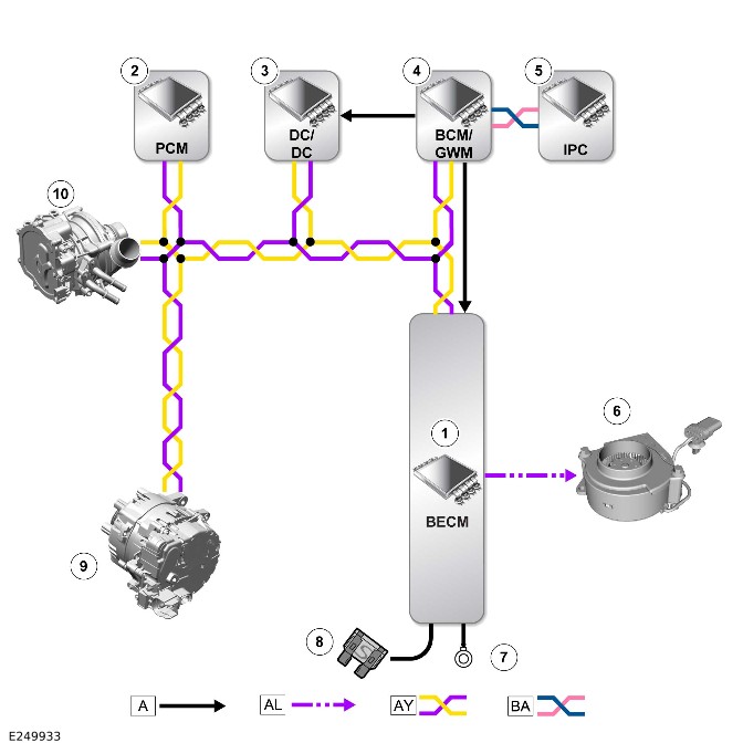
E249933

A = Hardwired: AL = PWM: AY = HS CAN power mode zero systems bus: BA = HS CAN Human Machine Interface (HMI) systems bus.

ItemDescription
1BECM - Integrated in the MHEV battery
2PCM
3DC/DC converter
4BCM/GWM
5IPC
6MHEV battery electric cooling fan
7Ground
8Power supply
9BISG
10Electric supercharger

Control Diagram - 2 of 2 - MHEV cables
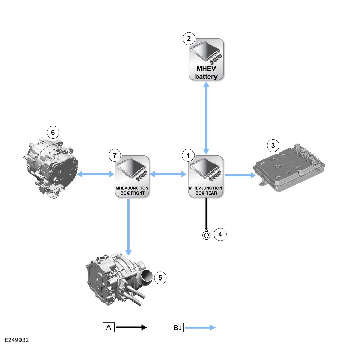
E249932

A = Hardwired: BJ = MHEV cables.

ItemDescription
1MHEV junction box - Rear
2MHEV battery
3DC/DC converter
4Ground
5Electric supercharger
6BISG
7MHEV junction box - Front

System architecture overview 1 of 2

P4, D4 and D6 Engines.

This schematic provides a high-level overview of the MHEV system architecture applicable to the vehicle and derivative selected. It is intended to give a general understanding of the system layout and component relationships.

For detailed circuit-level information, refer to the corresponding wiring diagrams.
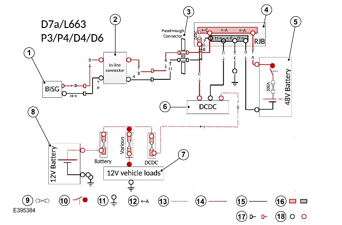
E395384

ItemDescription
1BISG
2Inline connector
3Passthrough connector
4Rear Junction Box (RJB)
548V Battery
6DC/DC converter
712V vehicle loads
812V Battery
9Fuse
10Battery contactor
11Ground connector
12Current flow
1312V circuit
1448V circuit
15Ground cable
16Bus Bar
17Connectors
18Eyelet connectors

System architecture overview 2 of 2

P6 Engine.
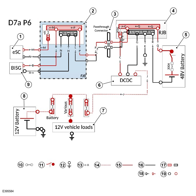
E395584

ItemDescription
1Electric supercharger
2Front junction box
3Passthrough connector
4RJB
548V battery
6DC/DC converter
712V vehicle loads
812V battery
9BISG
10Fuse
11Battery contactor
12Ground connector
13Current flow
1412V circuit
1548V circuit
16Ground cable
17Bus Bar
18Connectors
19Eyelet connectors

Direct Current to Direct Current Converter - RBoM - 110 (G4270285)

Part(s)

All vehicles

NameQuantityPart Number
Direct current to direct current converter (Main Component)1
Part Number(s)Superseded Part number(s)
LR131043

(Order if available)

LR172325
LR172325LR178516
LR178516433123456
433123456433123464
T2H46098

(Order if available)

T2H57005
T2H57005T2H57097
T2H57097T2H58330
T2H58330433123456
433123456433123464
LR173174

(Order if available)

LR178516
LR178516433123456
433123456433123464
433123464433123466
433123466433123473

Special Tool(s)

All vehicles

Lock BoxJLR-415-018 E226972
Lock-offJLR-415-098 E241733
Universal Cable Lock-offJLR-415-132 E269016

MHEV

Lock-offJLR-415-098 E241733

PHEV

Lock-offJLR-415-098 E241733
Universal Cable Lock-offJLR-415-132 E269016

Repair

Direct Current to Direct Current Converter - (110 and Non OCTA Vehicle) (414-01B REMOVAL AND INSTALLATION G2422535)

Published: 25-Feb-2026

2025.0 Defender (LE), 414-01B

Battery, Mounting and Cables - MHEV

Direct Current to Direct Current Converter - (110 and Non OCTA Vehicle) (G2422535)

REMOVAL AND INSTALLATION

  • 86.15.38
  • MHEV DC/DC Converter - Renew
  • 110
  • 0.40
  • USED WITHINS
  • 86.15.38.50
  • MHEV DC/DC Converter - Renew - With Occasional Rear Seats
  • 110
  • 0.80
  • USED WITHINS

General Equipment

Equipment name
Jaguar Land Rover approved diagnostic equipment

Part(s)

StepPart namePart NumberQualificationQuantity
Step 1Direct current to direct current converter (Main Component)
Part Number(s)Superseded Part number(s)
T2H46098

(Order if available)

T2H57005
T2H57005T2H57097
T2H57097T2H58330
T2H58330433123456
433123456433123464
LR173174

(Order if available)

LR178516
LR178516433123456
433123456433123464
433123464433123466
433123466433123473
LR131043

(Order if available)

LR172325
LR172325LR178516
LR178516433123456
433123456433123464
1

Removal

NOTE:

  • This procedure contains illustrations showing certain components removed to provide extra clarity.
  • This procedure contains some variation in the illustrations depending on the vehicle specification, but the essential information is always correct.

The following step(s) applies to:
All vehicles

  1. Power down the Mild Hybrid Electric Vehicle (MHEV) system.Refer to: MHEV Power Down/Up (414-01B Battery, Mounting and Cables - MHEV, General Procedures).

The following step(s) applies to:
All vehicles

  1. E409215
    • Remove the 2 clips.
    • Remove the bolt.
    • Release the Direct Current to Direct Current (DC/DC) converter lower air duct.
  2. E255228 Release the 2 clips and open the cover.
  3. E255229 Release the 3 clips and remove the terminal cover.
  4. NOTE:

    Note the position of the cables to aid installation.

    E255230
    • Disconnect the electrical connector.
    • Release the wiring harness clip.
    • Remove the 3 nuts.
    • Disconnect the 3 cables.
  5. E255234
    • Release the wiring harness clip.
    • Reposition the wiring harness away from the DC/DC converter.
  6. E255231 Release the 2 wiring harness clips from the left side of the DC/DC converter cover.
  7. E255232
    • Remove the 2 bolts.
    • Remove the 3 nuts.
    • Remove the DC/DC converter cover.
  8. E255233
    • Remove the 3 bolts.
    • Remove the DC/DC converter.

Installation

The following step(s) applies to:
All vehicles

    • Install the DC/DC converter.Renew Part (Main Component): Direct current to direct current converter Quantity: 1. Part Number: LR131043
    • Install and tighten the 3 bolts.Torque: 6Nm
    • Install the DC/DC converter cover.
    • Install and tighten the 2 bolts.Torque: 6Nm
    • Install and tighten the 3 bolts.Torque: 6Nm
  1. Install the 2 wiring harness clips to the left side of the DC/DC converter cover.
    • Reposition the wiring harness into the correct location.
    • Install the wiring harness clip.
  2. CAUTION:

    For all electrical eyelets make sure they are sitting flat and square to the receiving plastic location features before applying the final torque.

    • Connect the 3 cables.
    • Install and tighten the 3 nuts.TorqueM8: 12Nm M6: 10Nm
    • Connect the electrical connector.
    • Install the wiring harness clip.
  3. Install the terminal cover.
  4. Close the cover.
    • Install the DC/DC converter lower air duct.
    • Install the 2 clips.
    • Install and tighten the bolt.Torque: 3.2Nm

The following step(s) applies to:
All vehicles

  1. Power up the MHEV system.Refer to: MHEV Power Down/Up (414-01B Battery, Mounting and Cables - MHEV, General Procedures).
  2. Use the Jaguar Land Rover approved diagnostic equipment to configure the DC/DC converter.


Electric Power Inverter Converter 'D' (EPICD) - Software Update - RBoM - 110 (G4658563)

Part(s)

All vehicles

NameQuantityPart Number
Direct current to direct current converter (Main Component)0
Part Number(s)Superseded Part number(s)
LR173174

(Order if available)

LR178516
LR178516433123456
433123456433123464
433123464433123466
433123466433123473
LR131043

(Order if available)

LR172325
LR172325LR178516
LR178516433123456
433123456433123464
T2H46098

(Order if available)

T2H57005
T2H57005T2H57097
T2H57097T2H58330
T2H58330433123456
433123456433123464

Repair

Electric Power Inverter Converter 'D' (EPICD) - Software Update (414-01B GENERAL PROCEDURES G4747185)

Published: 13-Jan-2026

2025.0 Defender (LE), 414-01B

Battery, Mounting and Cables - MHEV

Electric Power Inverter Converter 'D' (EPICD) - Software Update (G4747185)

GENERAL PROCEDURES

  • 85.86.71
  • EPICD - Update ECU
  • MHEV
  • 0.20
  • USED WITHINS

Activation

  1. NOTE:

    Only complete this procedure if part of a repair plan within a fault and breakdown workflow.

    Continue to the next step of the workflow to complete the software download for the Electric Power Inverter Converter Control Module 'D' (EPICD).

MHEV Battery - RBoM - 90/110 (G4681376)

Part(s)

All vehicles

NameQuantityPart Number
MHEV Battery (Main Component)1
Part Number(s)Superseded Part number(s)
T2H49067

(Order if available)

T2H57429
T2H57429T2H59078
T2H59078429123473
429123473429123487
LR137929

(Order if available)

LR175174
LR175174LR181079
LR181079429123473
429123473429123487

Special Tool(s)

All vehicles

Lock BoxJLR-415-018 E226972
Lock-offJLR-415-098 E241733
Universal Cable Lock-offJLR-415-132 E269016

MHEV

Lock-offJLR-415-098 E241733

PHEV

Lock-offJLR-415-098 E241733
Universal Cable Lock-offJLR-415-132 E269016

Repair

MHEV Battery - 90/(110 and Non OCTA Vehicle) (414-01B REMOVAL AND INSTALLATION G2422562)

Published: 12-Apr-2024

2025.0 Defender (LE), 414-01B

Battery, Mounting and Cables - MHEV

MHEV Battery - 90/(110 and Non OCTA Vehicle) (G2422562)

REMOVAL AND INSTALLATION

  • 86.15.34
  • MHEV Battery - Renew
  • 110
  • 0.60
  • USED WITHINS

Removal

CAUTION:

Before disconnecting any components, make sure the area is clean and free from foreign material. When disconnected all openings must be sealed.

NOTES:

  • This procedure contains some variation in the illustrations depending on the vehicle specification, but the essential information is always correct.
  • This procedure contains illustrations showing certain components removed to provide extra clarity.
  • If the Mild Hybrid Electric Vehicle (MHEV) battery pack is being replaced a printed copy of the State Of Charge (SOC) report must be placed in the old MHEV battery pack return packaging.
  1. NOTE:

    If the MHEV battery is to be removed for access do not complete this step.

    Complete the Hybrid Battery Assessment and attach a copy inside the MHEV battery return packaging.Refer to: Hybrid Battery Assessment (414-01 Battery, Mounting and Cables - [+] MHEV, Description and Operation).
  2. NOTE:

    If the MHEV battery is to be removed for access do not complete this step.

    Complete the Battery Energy Control Module (BECM) - Traction Battery State of Health Overview and attach a copy inside the MHEV battery return packaging.Refer to: BECM - MHEV Battery State of Charge (414-00/BECM)
  3. Power down the MHEV system.Refer to: MHEV Power Down/Up (414-01B Battery, Mounting and Cables - MHEV, General Procedures).
  4. Remove the MHEV battery air duct.Refer to: MHEV Battery Housing Air Duct - (110 and Non OCTA Vehicle) (414-01B Battery, Mounting and Cables - MHEV, Removal and Installation). Refer to: MHEV Battery Housing Air Duct - 90 (414-01 Battery, Mounting and Cables - [+] MHEV, Removal and Installation).
  5. E254758 Disconnect the MHEV battery breather hose from the MHEV battery.
  6. E255152 Release the 2 wiring harness clips from the MHEV battery cover.
  7. E255151
    • Remove the 2 bolts.
    • Remove the nut.
    • Remove the MHEV battery cover.
  8. E255199
    • Remove the 6 bolts.
    • Remove the 3 brackets.
  9. E255198 Remove the MHEV battery.

Installation

  1. Install the MHEV battery.
    • Install the 3 brackets.
    • Install and tighten the 6 bolts.Torque: 10Nm
    • Install the MHEV battery cover.
    • Install and tighten the 2 bolts.Torque: 6Nm
    • Install and tighten the nut.Torque: 6Nm
  2. Install the 2 wiring harness clips to the MHEV battery cover.
  3. Connect the MHEV battery breather hose to the MHEV battery.
  4. Install the MHEV battery air duct.Refer to: MHEV Battery Housing Air Duct - (110 and Non OCTA Vehicle) (414-01B Battery, Mounting and Cables - MHEV, Removal and Installation). Refer to: MHEV Battery Housing Air Duct - 90 (414-01 Battery, Mounting and Cables - [+] MHEV, Removal and Installation).
  5. Power up the MHEV system.Refer to: MHEV Power Down/Up (414-01B Battery, Mounting and Cables - MHEV, General Procedures).
  6. NOTE:

    Only complete this step if a new component was installed.

    • Run the following routines.
    • BECM_ReplaceECU
    • MHEV_SOC
    • Powertrain Control Module (PCM)/Electric Power Inverter Converter Control Module 'D' (EPICD)/BECM SW update


MHEV Power Down/Up (G3191960)

GENERAL PROCEDURES

  • 01.01.60
  • MHEV - Power Down/Up
  • All Derivatives
  • 0.20
  • USED WITHINS

Special Tool(s)

E226972


JLR-415-018

Lock Box

 E241733


JLR-415-098

Lock-off

 E269016


JLR-415-132

Universal Cable Lock-off

General Equipment

Equipment name
Cable ties
Insulated padlock

Disconnection
WARNING:

All safety locking device keys must be kept in the designated key lock box at least 5 meters away from the vehicle.

NOTES:

  • This procedure contains some variation in the illustrations depending on the vehicle specification, but the essential information is always correct.
  • This procedure contains illustrations showing certain components removed to provide extra clarity.

The following step(s) applies to:
All vehicles

  1. This procedure involves working on the Mild Hybrid Electric Vehicle (MHEV) systems. It is mandated that the entire power down/up procedure is completed, all technicians involved with the steps in this procedure must have read and understood the relevant sections of the Electric Vehicle Safety Rules.Refer to: Electric Vehicle Safety Rules (414-01 Battery, Mounting and Cables - [+] PHEV, Description and Operation).
  2. Make sure that the vehicle is in Park (P), the Electric Park Brake (EPB) is released, the ignition is switched off and the doors are unlocked.
  3. E216616 Remove all smart keys from the vehicle and store at least 5 meters away from the vehicle, locked in the designated key box. Press the ignition switch to verify that there is no communication with the smart key.Special Tool(s): JLR-415-018
  4. Always refer to the health and safety precautions before carrying out this procedure.Refer to: Standard Workshop Practices (100-00 General Information, Description and Operation).
  5. Open the tailgate.
  6. Disconnect the 12V system.Refer to: 12V System Disconnect and Connect (414-00 Battery and Charging System - General Information, General Procedures).
  7. E276094 Disconnect the Battery Monitoring Sensor (BMS) electrical connector.
  8. E276095
    • Open the cover of the special tool.Special Tool(s): JLR-415-098
    • Install the startup battery ground cable into the special tool.
    • Install the cover.
    • Lock the special tool using an insulated padlock.General Equipment: Insulated padlock
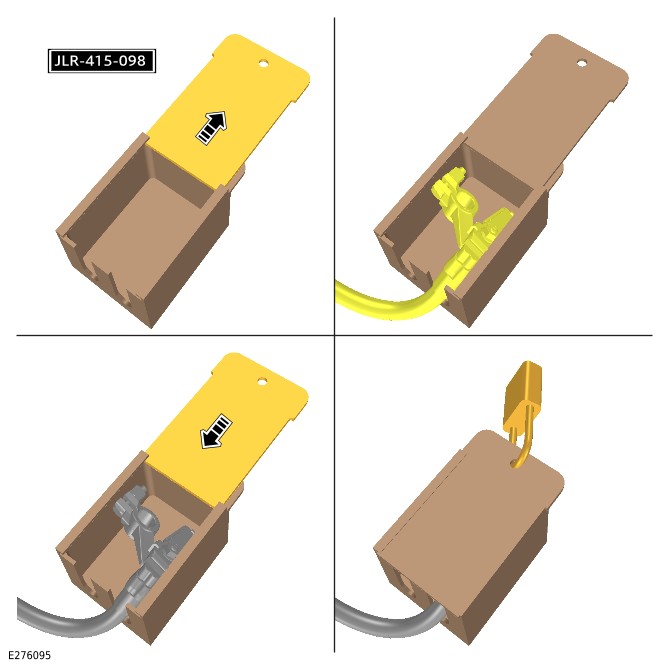
The following step(s) applies to:
Vehicles with 5 and 7 seats

  1. NOTE:

    Vehicles with 5 seats shown, vehicles with 7 seats similar.

    E255634 Remove the loadspace floor cover.
  2. NOTE:

    Vehicles with 5 seats shown, vehicles with 7 seats similar.

    E253184 Remove the stowage compartment.

The following step(s) applies to:
Vehicles with 8 seats

  1. NOTE:

    Vehicles with third row seats SRO to be claimed separately.

    Remove the third row seat.Refer to: Third Row Seat - 130 (501-10C Seating - Third Row Seats, Removal and Installation).
  2. E306458 Disconnect the electrical connector.
  3. E306459
    • Remove the 4 retaining clips.
    • Remove the air duct.

The following step(s) applies to:
Commercial vehicles

  1. NOTE:

    Commercial vehicles SRO to be claimed separately.

    Remove the loadspace rear trim panel.Refer to: Loadspace Rear Trim Panel - Vehicles With: Commercial Specification (501-05 Interior Trim and Ornamentation, Removal and Installation).
  2. NOTE:

    Repeat this step for the other side.

    E370503
    • Remove the 2 bolts.
    • Remove the bracket.
  3. E274787
    • Remove the 14 screws.
    • Remove the rear stowage compartment.

The following step(s) applies to:
All vehicles

  1. E306460 Disconnect the electrical connector from the MHEV battery.
  2. gloves goggles WARNING:

    Wear safety goggles and protective gloves.

    E306461
    • Reposition the cover to get access to the nut.
    • Remove the nut.
    • Disconnect the MHEV battery ground cable.
  3. E275627
    • Open the cover of the special tool.Special Tool(s): JLR-415-132
    • Install the MHEV battery negative cable into the tool at the position illustrated.
    • Install the cover.
    • Lock the special tool using an insulated padlock.General Equipment: Insulated padlock
  4. E306463
    • Reposition the cover to get access to the nut.
    • Remove the nut.
    • Disconnect the MHEV battery positive cable and tie aside.General Equipment: Cable ties

Connect

The following step(s) applies to:
All vehicles

  1. E306464
    • Connect the MHEV battery positive cable.
    • Install and tighten the nut.Torque: 10Nm
    • Remove and discard the cable tie.
  2. E275668
    • Remove the insulated padlock.
    • Remove the cover.
    • Remove the MHEV battery negative cable.
    • Install the cover.
  3. gloves goggles WARNING:

    Wear safety goggles and protective gloves.

    E306462
    • Connect the MHEV battery negative cable.
    • Install and tighten the nut.Torque: 12Nm
    • Reposition the cover.
  4. Connect the electrical connector from the MHEV battery.

The following step(s) applies to:
Commercial vehicles

  1. Install the rear stowage compartment.
  2. NOTE:

    Repeat this step for the other side.

    • Install the bracket.
    • Install and tighten the 2 bolts.Torque: 3.5Nm
  3. Install and tighten the 14 rear stowage compartment screws.Torque: 3.5Nm
  4. NOTE:

    Commercial vehicles SRO to be claimed separately.

    Install the loadspace rear trim panel.Refer to: Loadspace Rear Trim Panel - Vehicles With: Commercial Specification (501-05 Interior Trim and Ornamentation, Removal and Installation).

The following step(s) applies to:
Vehicles with 8 seats

    • Install the air duct.
    • Install the 4 retaining clips.
  1. Connect the electrical connector.
  2. NOTE:

    Vehicles with third row seats SRO to be claimed separately.

    Install the third row seat.Refer to: Third Row Seat - 130 (501-10C Seating - Third Row Seats, Removal and Installation).

The following step(s) applies to:
Vehicles with 5 and 7 seats

  1. NOTE:

    Vehicles with 5 seats shown, vehicles with 7 seats similar.

    Install the stowage compartment.
  2. NOTE:

    Vehicles with 5 seats shown, vehicles with 7 seats similar.

    Install the loadspace floor cover.

The following step(s) applies to:
All vehicles

  1. E276095
    • Remove the insulated padlock.
    • Open the cover of the special tool.Special Tool(s): JLR-415-098
    • Remove the startup battery ground cable from the special tool.
    • Close the cover on the special tool.
  2. Connect the BMS electrical connector.
  3. Connect the 12V system.Refer to: 12V System Disconnect and Connect (414-00 Battery and Charging System - General Information, General Procedures).


Battery Charging - INGENIUM I6 3.0L Petrol/INGENIUM I6 3.0L Diesel, Vehicles With: MHEV

Direct Current to Direct Current Converter (G2391071)

DESCRIPTION AND OPERATION

COMPONENT LOCATION

Component Location - 1 of 1
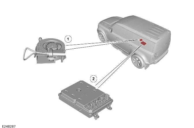
E248287

ItemDescription
1Direct Current to Direct Current converter (DC/DC) electric cooling fan
2DC/DC

OVERVIEW

The DC/DC changes the 48V Direct Current (DC) of Mild Hybrid Electric Vehicle (MHEV) battery to the 12V for the vehicle electrical systems.

For additional information, refer to: MHEV Battery and Cables - Non OCTA Vehicle (414-01B Battery, Mounting and Cables - MHEV, Description and Operation).

The DC/DC supplies all the current for the 12V systems and to charge the startup battery.

For additional information, refer to: Startup Battery and Cables - INGENIUM I6 3.0L Petrol/INGENIUM I6 3.0L Diesel (414-01B Battery, Mounting and Cables - MHEV, Description and Operation).

DESCRIPTION

DC/DC
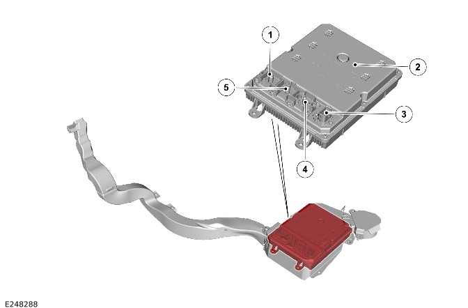
E248288

ItemDescription
1Startup battery cable terminal
2DC/DC
3Wiring harness connector
4MHEV battery cable terminal
5Ground cable terminal

The DC/DC is located in the DC/DC housing. The DC/DC is secured on 3 studs to the lower DC/DC housing with 3 nuts.

The DC/DC is supplied with power from the MHEV battery. The DC/DC converts the MHEV battery voltage from approximately 48V DC to the 12V DC for the following:

  • All the vehicles 12V systems.
  • The startup battery.

The output from the DC/DC charges the startup battery and provides all the electrical power for all the 12V components. The output from the DC/DC is approximately 14V.

The DC/DC supplies all the power for the startup battery. The DC/DC power for all the vehicle 12V systems in all Power Modes except in Power Mode 0 (vehicle locked and armed).

For additional information, refer to: Startup Battery and Cables - INGENIUM I6 3.0L Petrol/INGENIUM I6 3.0L Diesel (414-01B Battery, Mounting and Cables - MHEV, Description and Operation).

The DC/DC has 4 electrical connections for the following:

  • MHEV battery cable terminal from the MHEV battery junction box.
    • For additional information, refer to: Startup Battery and Cables - INGENIUM I6 3.0L Petrol/INGENIUM I6 3.0L Diesel (414-01B Battery, Mounting and Cables - MHEV, Description and Operation).
  • Ground cable terminal from the MHEV battery junction box.
    • For additional information, refer to: Startup Battery and Cables - INGENIUM I6 3.0L Petrol/INGENIUM I6 3.0L Diesel (414-01B Battery, Mounting and Cables - MHEV, Description and Operation).
  • The 12V DC output to the BJB for the startup battery and the vehicle 12V systems.
    • For additional information, refer to: Startup Battery and Cables - INGENIUM I6 3.0L Petrol/INGENIUM I6 3.0L Diesel (414-01B Battery, Mounting and Cables - MHEV, Description and Operation).
  • Wiring harness connector with 10-pin connections for the following:
    • Power supply from the Body Control Module (BCM)/Gateway Control Module (GWM).
    • Power supply to the DC/DC electric cooling fan.
    • Ground for the DC/DC electric cooling fan.
    • Pulse Width Modulation (PWM) signal to the DC/DC electric cooling fan.
    • High Speed (HS) Controller Area Network (CAN) power mode zero systems bus (quantity 2).
    • A ground connection.

NOTE:

Not all the connection pins in the wiring harness connector are used.

The DC/DC controls the DC/DC electric cooling fan with a PWM signal.

DC/DC Electric Cooling Fan
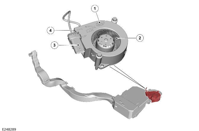
E248289

ItemDescription
1DC/DC electric cooling fan
2Cooling air inlet
3Wiring harness connector
4Cooling air outlet

The DC/DC electric cooling fan is located in the DC/DC housing. The DC/DC electric cooling fan is attached to the lower DC/DC housing with 2 bolts.

The DC/DC electric cooling fan is hardwired to the DC/DC. The DC/DC electric cooling fan has a 3-pin wiring harness connector on a fly lead. The 4-pin connector has the following electrical connections:

  • Power supply from the DC/DC.
  • A PWM signal from the DC/DC.
  • A ground through the DC/DC.

NOTE:

Not all the connection pins in the wiring harness connector are used.

The DC/DC controls the speed of the DC/DC electric cooling fan depending on cooling requirements. The DC/DC uses a PWM signal to control the DC/DC electric cooling fan speed.

Air Ducts

CAUTION:

Make sure that the air duct inlet below the rear right second row seat is not obstructed.
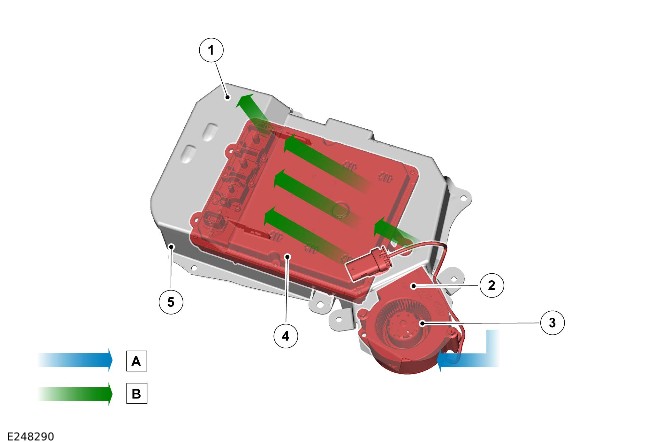
E248290

ItemDescription
AInlet air
BOutlet air
1Outlet air duct of the DC/DC
2Outlet air duct from the DC/DC electric cooling fan to the DC/DC
3DC/DC electric cooling fan
4DC/DC
5DC/DC housing

The inlet air duct directs the air from the passenger compartment to the DC/DC electric cooling fan.

The outlet air duct directs the air from the DC/DC electric cooling fan to cool the DC/DC when required. After cooling the DC/DC, the air exits the DC/DC housing.

OPERATION

The DC/DC converts the MHEV battery DC voltage of approximately 48V DC to 12V DC.

The DC/DC supplies all the vehicle 12V systems and charges the startup battery. The DC/DC communicates with the BCM/GWM. The DC/DC communicates through the HS CAN power mode zero systems bus. The BCM/GWM sends charging load requests and the DC/DC produces the correct output voltage and current to match the vehicle electrical load requests.

The electrical systems are powered from the DC/DC in all modes except in Power Mode 0 (vehicle locked and armed). The DC/DC also charges the startup battery through the BJB.

For additional information, refer to: Startup Battery and Cables - INGENIUM I6 3.0L Petrol/INGENIUM I6 3.0L Diesel (414-01B Battery, Mounting and Cables - MHEV, Description and Operation).

For additional information, refer to: MHEV Battery and Cables - Non OCTA Vehicle (414-01B Battery, Mounting and Cables - MHEV, Description and Operation).

The HS CAN power mode zero systems bus is also connected to the following:

  • The Battery Energy Control Module (BECM) in the MHEV battery.
  • The Powertrain Control Module (PCM).
  • TheBCM/GWM.

DC/DC Temperature Control

The DC/DC is cooled by the DC/DC electric cooling fan. Operation of the DC/DC electric cooling fan is controlled by the DC/DC. The DC/DC has temperature sensors within the housing to monitor the internal temperatures. The DC/DC reports the internal temperature data to the PCM. The signal is sent through the HS CAN power mode zero systems bus.

The operation and speed of the DC/DC electric cooling fan is determined by the PCM, using internal temperature data and a computer model. Then the PCM sends the fan speed control signal back to the DC/DC. The DC/DC generates a PWM to control the DC/DC electric cooling fan speed. The lower DC/DC housing is finned to increase the surface area for the air to cool the DC/DC.

Diagnostics

The BCM/GWM records any Diagnostic Trouble Code (DTC) and related data. The DTC and related data are read using the Jaguar Land Rover (JLR) approved diagnostic equipment.

The JLR approved diagnostic equipment enables certain components to be activated and also read live data.

CONTROL DIAGRAM

CONTROL DIAGRAM - 1 of 1
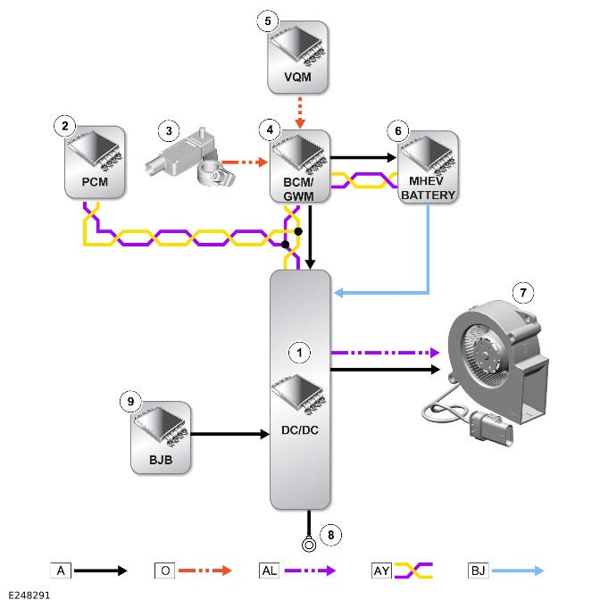
E248291

A = Hardwired: O = Local Interconnect Network (LIN): AL = PWM: AY = HS CAN power mode zero systems bus: BJ = MHEV battery cable.

ItemDescription
1DC/DC
2PCM
3Battery Monitoring System (BMS) control module
4BCM/GWM
5Voltage Quality Module (VQM)
6MHEV battery
7DC/DC electric cooling fan
8Ground
9BJB


Battery Charging Systems (G4743176)

DIAGNOSIS AND TESTING

Principles of Operation

For a detailed description of the Mild Hybrid Electric Vehicle (MHEV) Battery and Cables, refer to the relevant Description and Operation section in the workshop manual. REFER to:

Startup Battery and Cables - INGENIUM I6 3.0L Petrol/INGENIUM I6 3.0L Diesel (414-01B Battery, Mounting and Cables - MHEV, Description and Operation),
MHEV Battery and Cables - Non OCTA Vehicle (414-01B Battery, Mounting and Cables - MHEV, Description and Operation),
Direct Current to Direct Current Converter (414-03A Battery Charging - INGENIUM I6 3.0L Petrol/INGENIUM I6 3.0L Diesel, Vehicles With: MHEV, Description and Operation).

Inspection and Verification

CAUTION:

Diagnosis by substitution from a donor vehicle is NOT acceptable. Substitution of control modules does not guarantee confirmation of a fault, and may also cause additional faults in the vehicle being tested and/or the donor vehicle.

NOTE:

  • If a control module or a component is at fault or may be at fault and the vehicle remains under manufacturer warranty, refer to the Warranty Policy and Procedures manual, or determine if any prior approval program is in operation, prior to the installation of a new module/component.
  • When performing voltage or resistance tests, always use a digital multimeter that has the resolution ability to view 3 decimal places. For example, on the 2 volts range can measure 1 mV or 2 kΩ range can measure 1 Ω. When testing resistance always take the resistance of the digital multimeter leads into account.
  • Check and rectify basic faults before beginning diagnostic routines involving pinpoint tests.
  • It is not permissible to disassemble the MHEV battery.
  1. Verify the customer concern.
  1. Visually inspect for obvious signs of mechanical or electrical damage.
MechanicalElectrical
  • Belt integrated starter generator drive beltBelt Integrated Starter Generator (BISG)
  • Fuses
  • Wiring harness and connectors
  • 48V wiring harness and connectors
  • MHEV battery
  1. If an obvious cause for an observed or reported concern is found, correct the cause (if possible) before proceeding to the next step
  1. If the cause is not visually evident, verify the symptom and refer to the Symptom Chart.

Symptom Chart

NOTE:

The images, connectors and procedures below are applicable to D8 platform vehicles. The details may differ slightly for other models.
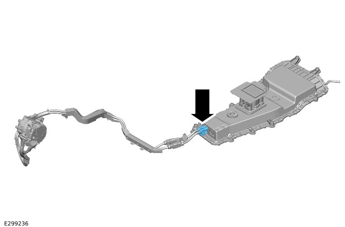
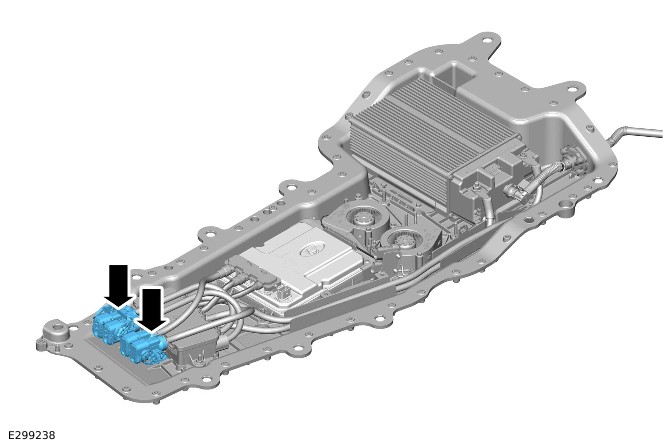
SYMPTOMPOSSIBLE CAUSESACTION
  • Flat 12V battery
  • The 48V MHEV pass through connectors have arcing damage
NOTE:

The poor connection of the 48V cable connectors can cause the Battery Energy Control Module (BECM) internal relay to open, which causes the Direct Current to Direct Current (DC/DC) to falsely detect there is a short circuit

  • The 48V cable connectors (C1DC18C and C1DC18D) have a latching device on the connector. The latching device on this connector DOES NOT assist the connector into the fully 'home' position
  • The 48V cable connectors (C1DC18C and C1DC18D) could have a backed out terminal, which could cause arcing damage
  • The 48V cable inline connectors (C11HA5, C11HA6, C11HA7 and C11HA8) could have a backed out terminal, which could cause arcing damage
  • The torque of the fixings for the 48V Battery / DC/DC terminal connections are out of specification
NOTE:

Whenever completing the installation of the 48V ground cable connectors, make sure the 48V connector is pushed in to the fully 'home' position before closing the latching device

  • Refer to the relevant Description and Operation procedures to make sure you understand components and component locations before conducting any work
  • If any of the components are found to be damaged due to arcing, replace the components. Follow the relevant Removal and Installation procedures for guidance and torque figures
  • Refer to the service instruction below: '48V Connector Arcing' for examples of arcing and correct connector installation
  • Using the Jaguar Land Rover approved diagnostic equipment, run application - DC/DC Check Status FD 84
  • Flat 12V battery
NOTE:

The poor connection of the 12V cable connectors can cause the BECM internal relay to open, which causes the DC/DC to falsely detect there is a short circuit

  • The connector (C1YB01A) has too much 'side load', which is created by the incorrect positioning of the harness (LR162459) fixing
  • Intermittent connection of the 12V harness to the BECM
  • When the DC/DC converter has been replaced:
    • The harness has not been replaced with a newer (updated) harness
    • The harness has been replaced incorrectly
NOTE:

Vehicles from original manufacture may have the incorrect harness fixing position. The Harness has been updated since original manufacture. It is good practice to make sure the harness is changed when the MHEV battery is changed

  • Replace the harness (LR162459). For guidance, follow the service instructions below: 'Harness Fixing Positioning' showing correct harness fixing positioning.
  • Using the Jaguar Land Rover approved diagnostic equipment, run application - DC/DC Check Status FD 84

Service Instruction: 48V Connector Arcing

NOTE:

The images, connectors and procedures below are applicable to D8 platform vehicles. The details may differ slightly for other models.
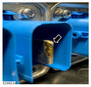
DescriptionImage / Illustration
  • The illustration on the right is an overview of the MHEV system (48v)
    • The 48V cable connectors (C1DC18C and C1DC18D) are highlighted in the illustration with an arrow
E299236
  • The illustration on the right is zoomed in to the 48V connectors
    • The 48V cable connectors (C1DC18C and C1DC18D) could have a backed-out terminal, which could cause arcing damage. An example of arcing damage can be found below
E299238
  • The Image to the right shows a damaged 48V connector
    • The damage is caused by a poor connection of the connector
    • Visually inspect all connectors for evidence of arcing damage. If this damage is observed on any of the 48V connectors or if any of the components are found to be damaged due to arcing, replace the components. Follow the relevant Removal and Installation procedures for guidance
E299234
  • The Illustration to the right shows 2 states of the 48V connector
    • State 1 (on the left) shows a poor connection. This is a NOT OK state. The positioning of this connection is likely to cause arcing damage
    • State 2 (on the right) shows a good connection. This is an OK state. The positioning of this connection means there is reduced risk of the components arcing
E299235
  • The Illustration to the right shows latching device on the 48V connector
    • The 48V cable connectors (C1DC18C and C1DC18D) have a latching device on the connector. The latching device on this connector DOES NOT assist the connector into the fully 'home' position.
  • Referring to the above instruction:
    • When the connector is in State 2 (OK), it is safe to close the latching system on this connector.
E299237

Service Instruction: Harness Fixing Positioning

NOTE:

The images, connectors and procedures below are applicable to D8 platform vehicles. The details may differ slightly for other models.
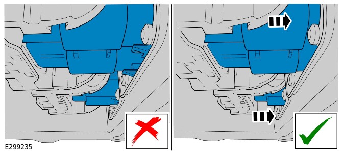
Positioning Of LR162459 FixingIllustration of LR162459
  • Incorrect positioning of the fixing on LR162459
E298193
  • Correct positioning of the fixing on LR162459
E298192


Communications Network - 110 (G2342562)

DESCRIPTION AND OPERATION

COMPONENT LOCATION

Component Location - 1 Of 3

NOTE:

Right Hand Drive (RHD) vehicle is shown, Left Hand Drive (LHD) vehicle is similar.
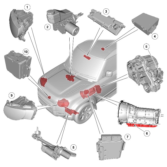
E249780

ItemDescription
1Headlamp Control Module B (HCMB)
2Anti-Lock Brake System Control Module (ABS)
3Image Processing Module (IPMA)
4Tire Pressure Monitoring System Control Module (TPM)
5Transfer Case Control Module (TCCM)
6Transmission Control Module (TCM)
7Powertrain Control Module (PCM)
8Power Steering Control Module (PSCM)
9Headlamp Control Module A (HCM)
10Cruise Control Module (CCM)

Component Location - 2 Of 3

NOTE:

RHD vehicle is shown, LHD vehicle is similar.
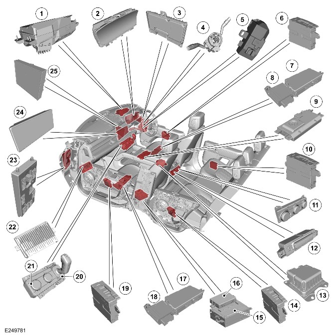
E249781

ItemDescription
1Head Up Display (HUD)
2
3>span class="acronym">Driver Assistance Domain Controller (DADC)
4Steering Wheel Module (SWM)
5Electric Steering Column Lock Control Module (VIM)
6Driver Door Control Module (DDM)
7Seat Module - Driver/Passenger/Rear - Left/Right (DSM)
8Driver Seat Climate Control Module (DSCCM)
9Wireless Device Charger Module (WDCM)
10Driver Rear Door Module (DRDM)
11Rear Integrated Control Panel (FCIMB) (if equipped)
12Second row seat heater control (if equipped)
13Restraints Control Module (RCM)
14Passenger Rear Door Module (PRDM)
15Front Infotainment Control Module (IGM / ICCM)
16Remote Function Actuator (RFA)
17Seat Module - Driver/Passenger/Rear - Left/Right (PSM)
18Passenger Seat Climate Control Module (PSCCM)
19Passenger Door Control Module (PDM)
20Transmission Control Switch (TCS)
21Integrated Control Panel (FCIM)
22Near Field Sensing Module (NFSM)
23Body Control Module (BCM)/Gateway Control Module (GWM)
24Touch Screen (FCDIM)
25Heating, ventilation, and air conditioning (HVAC) control module

Component Location - 3 Of 3

NOTE:

RHD vehicle is shown, LHD vehicle is similar.
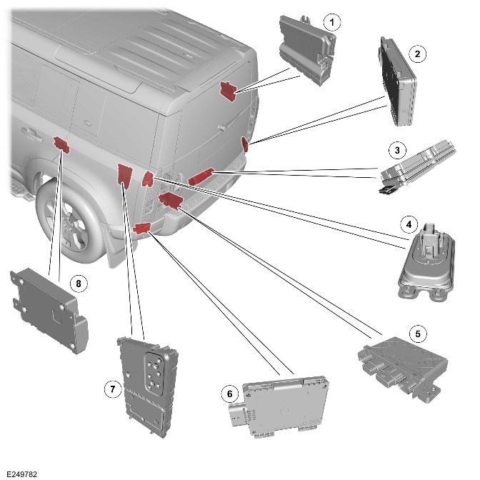
E249782

ItemDescription
1Chassis Control Module (CHCM)
2Side Obstacle Detection Control Module - Right (SODR)
3Rear Differential Control Module (RDCM)
4Voltage Quality Module (VQM)
5Towbar Control Module (TBM)
6Side Obstacle Detection Control Module - Left (SODL)
7Audio Amplifier Control Module (AAM)
8Telematics Control Module (TCU)

OVERVIEW

A number of different types of communication network are incorporated into the vehicle wiring harnesses for the transmission of commands and information between control modules. The configuration installed on a particular vehicle depends on the model and equipment level.

NOTE:

The control diagrams shown in this section are schematics reflecting communications networks installed to RHD vehicles only. For detailed layouts of the various communications networks installed to RHD and LHD vehicles refer to the electrical guide.

The communications networks available on the vehicle are shown below:

  • Ethernet
  • FlexRay
  • High Speed (HS) Controller Area Network (CAN) diagnostic bus
  • HS CAN Human Machine Interface (HMI) systems bus
  • HS CAN body systems bus
  • HS CAN power mode zero systems bus
  • HS CAN Underbody (UN) systems bus
  • HS CAN powertrain systems bus
  • Private CAN bus
  • Local Interconnect Network (LIN).

Diagnostic Connector

The Diagnostic Connector (J1962) is connected to the BCM/GWM through the Diagnostic over Internet Protocol (DoIP) and the HS CAN diagnostic bus. The DoIP is the prime connection for the Jaguar Land Rover (JLR) approved diagnostic equipment.

DESCRIPTION

Refer to the relevant system section for details of system description.

OPERATION

Refer to the relevant system section for details of system operation.

CONTROL DIAGRAM

High Speed Controller Area Network Diagnostic Bus
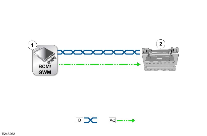
E248262

D = HS CAN diagnostic bus: A C = DoIP.

ItemDescription
1BCM/GWM
2J1962

Ethernet

E248263

AW = Ethernet: BF = Ethernet Wake-up.

ItemDescription
1BCM/GWM
2NFSM
3TCU
4J1962
5AAM
6IGM / ICCM
7IPMA
8DADC

FlexRay

E248264

AX = FlexRay.

ItemDescription
1BCM/GWM
2PCM
3DADC
4PSCM
5SWM
6ABS
7RCM
8NFSM
9TCM
10CHCM
11TCCM

High Speed Controller Area Network Human Machine Interface Systems Bus
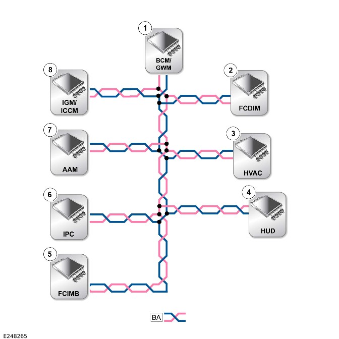
E248265

BA = HS CAN HMI systems bus.

ItemDescription
1BCM/GWM - Terminator module
2FCDIM
3HVAC control module
4HUD
5FCIMB
6IPC - Terminator module
7AAM
8IGM / ICCM

High Speed Controller Area Network Body Systems Bus
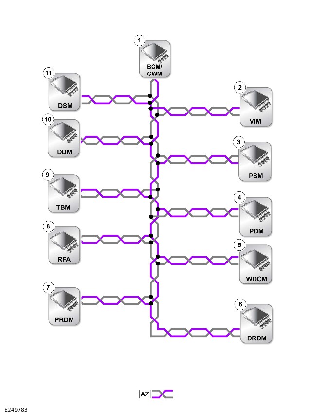
E249783

AZ = HS CAN body systems bus.

ItemDescription
1BCM/GWM - Terminator (quantity 2) module
2VIM
3PSM
4PDM
5WDCM
6DRDM
7PRDM
8RFA
9TBM
10DDM
11DSM

High Speed Controller Area Network Power Mode Zero Systems Bus
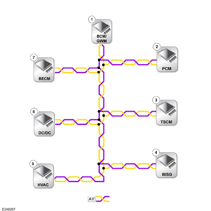
E248267

AY = HS CAN power mode zero systems bus.

ItemDescription
1BCM/GWM - Terminator module
2PCM - Only Ingenium I6 3.0L petrol
3Turbocharger / Supercharger Control Module (TSCM) (if equipped)
4Belt Integrated Starter Generator (BISG) (if equipped)
5HVAC control module - Terminator module
6Direct Current to Direct Current converter (DC/DC) (if equipped)
7Battery Energy Control Module (BECM) (if equipped)

High Speed Controller Area Network Underbody Systems Bus
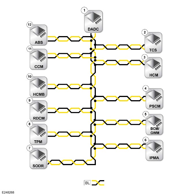
E248268

BL = HS CAN UN Systems Bus.

ItemDescription
1DADC - Terminator module
2TCS
3HCM
4PSCM
5BCM/GWM
6IPMA
7SODR
8TPM
9RDCM
10HCMB
11CCM
12ABS - Terminator module

High Speed Controller Area Network Powertrain Systems Bus
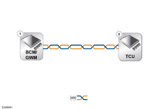
E258941

AN = HS CAN powertrain Systems bus.

ItemDescription
1BCM/GWM - Terminator module
2TCU - Terminator module

Private Controller Area Network Bus - 1 Of 4 - Blindspot Monitoring Control Circuit
E248270

U = Private CAN bus.

ItemDescription
1SODL
2SODR

Private Controller Area Network Bus - 2 of 4 - Driver Assistance Domain Controller Control Circuit
E248271

U = Private CAN bus.

ItemDescription
1DADC
2CCM

Private Controller Area Network Bus - 3 of 4 - HVAC control Circuit
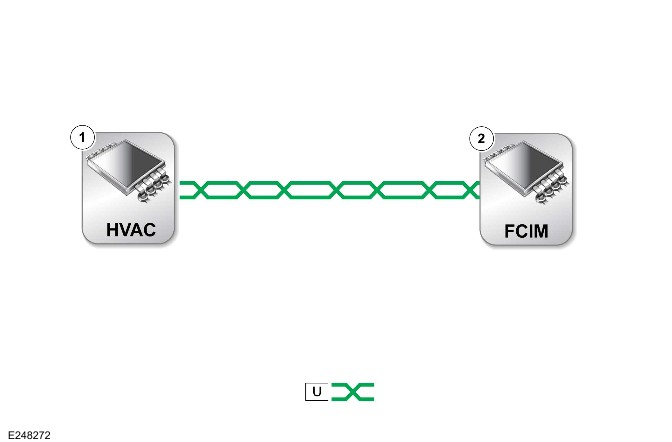
E248272

U = Private CAN bus.

ItemDescription
1HVAC control module
2FCIM

Private Controller Area Network Bus - 4 of 4 - Headlamp control Circuit
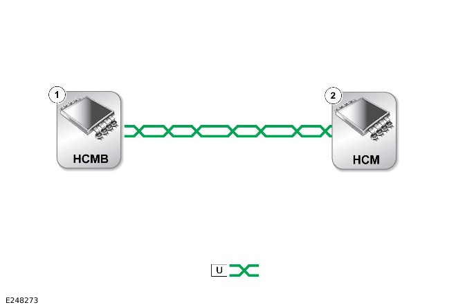
E248273

U = Private CAN bus.

ItemDescription
1HCMB
2HCM

Local Interconnect Network - 1 Of 11 - Body Control Module/Gateway Control Module Control Circuit
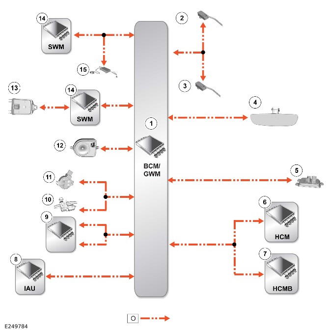
E249784

O = LIN.

ItemDescription
1BCM/GWM
2Ambience lighting Light Emiting Diode (LED) - Instrument panel
3Ambience lighting LED - Console
4Rear View Mirror (RVM)
5VQM
6HCM
7HCMB
8Immobilizer Antenna Unit (IAU)
9Roof opening panel control module (glass roof has 1 node, canvas roof has 2 nodes)
10Wiper motor - Front window
11Rain/light sensor
12Battery Back-Up Sounder (BBUS)
13Right steering wheel switch
14SWM
15Volumetric sensor

Local Interconnect Network - 2 Of 11 - Left Steering Wheel Switch
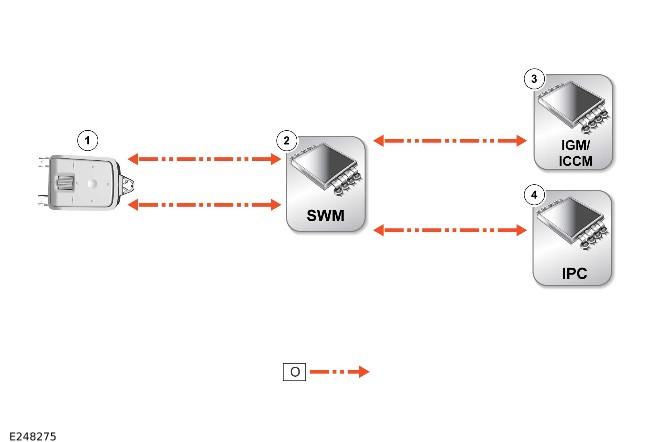
E248275

O = LIN.

ItemDescription
1Left steering wheel switch
2SWM
3IGM / ICCM
4IPC

Local Interconnect Network - 3 of 11 - Powertrain Control Module Control Circuit
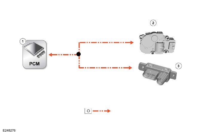
E248276

O = LIN.

ItemDescription
1PCM
2Active grille air shutter motor
3Glow plug control module (diesel vehicles only)

Local Interconnect Network - 4 Of 11 - Battery Monitoring System
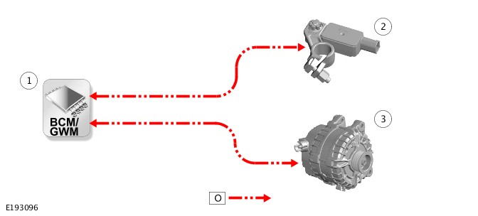
E193096

O = LIN.

ItemDescription
1BCM/GWM
2Battery Monitoring System (BMS) control module
3Generator

Local Interconnect Network - 5 Of 11 - HVAC Control Module
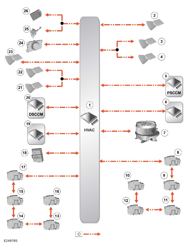
E249785

O = LIN.

ItemDescription
1HVAC control module
2Seat heater - Passenger
3Seat heater - Second row left
4Seat heater - Third row left
5PSCCM
6Rear Seat Climate Control Module (RSCCM) - Left
7Blower - Front
8Recirculation motor
9Cool air bypass motor
10Distribution motor - Front left
11Temperature blend motor - Front left
12Temperature blend motor - Rear left
13Temperature blend motor - Front right
14Temperature blend motor - Rear right
15Auxiliary climate control face/feet motor
16Distribution motor - Front right
17Distribution motor - Demist
18Humidity sensor
19RSCCM - Right
20DSCCM
21Seat heater - Second row right
22Seat heater - Third row right
23Seat heater - Driver
24Auxiliary blower rotary control
25Fuel Fired Booster Heater Control Module (AHCM)
26AHCM receiver

Local Interconnect Network - 6 Of 11 - Driver Door Control Module Control Circuit
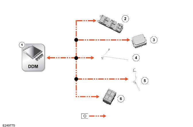
E249775

O = LIN.

ItemDescription
1DDM
2Door switchpack - Driver
3Clear Exit Detection System (CEDS) indicator
4Ambience lighting LED - Driver door
5Ambience lighting LED - Driver door handle
6Seat memory switchpack - Driver

Local Interconnect Network - 7 Of 11 - Passenger Door Control Module Control Circuit
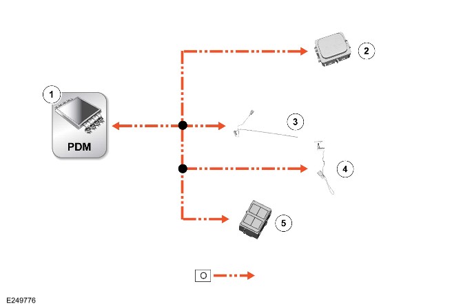
E249776

O = LIN.

ItemDescription
1PDM
2CEDS indicator
3Ambience lighting LED - Passenger door
4Ambience lighting LED - Passenger door handle
5Seat memory switchpack - Passenger

Local Interconnect Network - 8 Of 11 - Driver Rear Door Module Control Circuit
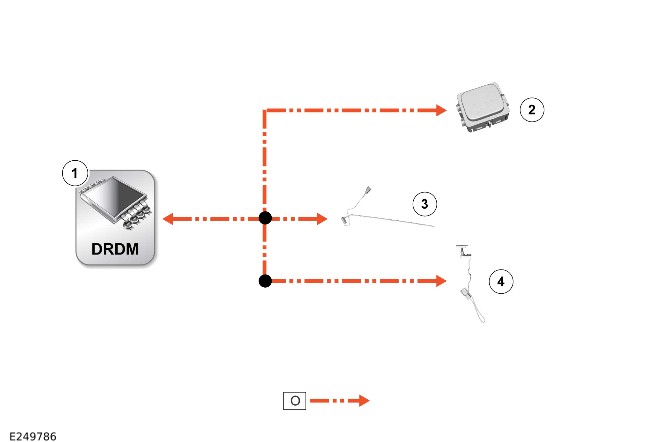
E249786

O = LIN.

ItemDescription
1DRDM
2CEDS indicator
3Ambience lighting LED - Rear right door
4Ambience lighting LED - Rear right door handle

Local Interconnect Network - 9 Of 11 - Passenger Rear Door Module Control Circuit
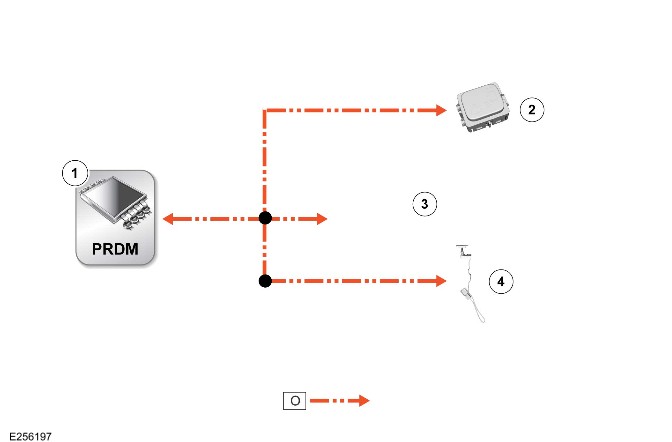
E256197

O = LIN.

ItemDescription
1PRDM
2CEDS indicator
3Ambience lighting LED - Rear left door
4Ambience lighting LED - Rear left door handle

Local Interconnect Network - 10 Of 11 - Driver Seat Module Control Circuit
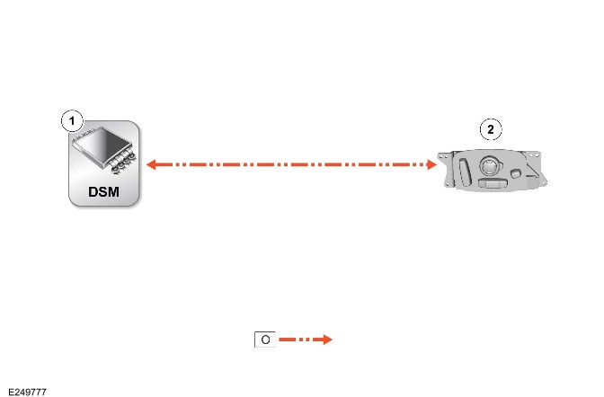
E249777

O = LIN.

ItemDescription
1DSM
2Seat switchpack - Driver

Local Interconnect Network - 11 Of 11 - Passenger Seat Module Control Circuit
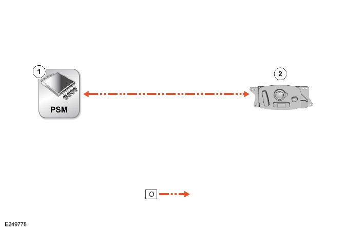
E249778

O = LIN.

ItemDescription
1PSM
2Seat switchpack - Passenger

Communications Network (G1818411)

DIAGNOSIS AND TESTING

Principles of Operation

For a detailed description of the Communications Network, refer to the relevant Description and Operation section in the workshop manual. REFER to: Communications Network - 110 (418-00 Module Communications Network, Description and Operation).

Inspection and Verification

CAUTION:

Diagnosis by substitution from a donor vehicle is NOT acceptable. Substitution of control modules does not guarantee confirmation of a fault, and may also cause additional faults in the vehicle being tested and/or the donor vehicle.

NOTES:

  • If a control module or a component is at fault or may be at fault and the vehicle remains under manufacturer warranty, refer to the Warranty Policy and Procedures manual, or determine if any prior approval program is in operation, prior to the installation of a new module/component.
  • When performing voltage or resistance tests, always use a digital multimeter accurate to three decimal places, and with an up-to-date calibration certificate. When testing resistance always take the resistance of the digital multimeter leads into account.
  • Inspect and rectify basic faults before beginning diagnostic routines involving pinpoint tests.
  1. Verify the customer concern
  1. Visually inspect for obvious signs of damage and system integrity

Visual Inspection

Electrical
  • Fuses
  • Wiring harnesses and connectors
  • Control modules
  1. If an obvious cause for an observed or reported concern is found, correct the cause (if possible) before proceeding to the next step
  1. If the cause is not visually evident, verify the symptom and refer to the Symptom Chart, alternatively check for Diagnostic Trouble Codes (DTCs) and refer to the DTC Index
  1. Inspect the JLR claims submission system for open campaigns. Refer to the corresponding bulletins and SSMs which may be valid for the specific customer complaint and complete the recommendations as required.

COMMUNICATION NETWORK FAILURE PROCEDURE

The following instructions are for vehicles using the Jaguar Land Rover (JLR) approved diagnostic equipment.

If a fault is suspected or is reported by the customer then the TOPIx Cloud guided diagnostic should be followed using the fault and breakdown workflow. This gives the most reliable route to a right first time repair. The diagnostic may include investigation of other linked systems and software.
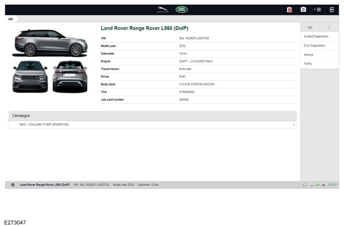
E273047

This will display a list of all control modules that are installed on the vehicle.

  • Control modules that are communicating correctly will show a green tick at the left of the screen
  • Control modules are not communicating will show a red cross at the left off the screen

This check can be used to determine if either a single module or multiple modules are failing to communicate (as seen in the image below).
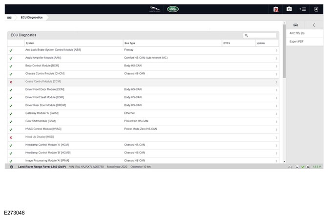
E273048

When all non-communicating module(s) have been identified, refer to the vehicle wiring diagrams (418-00 module communications), to identify the communication network at fault. If a single control module is failing to communicate inspect the module power supply circuit before continuing. When the communication network at fault has been identified and the non-communicating module(s) power supply has been confirmed, the approximate location of the network failure can be localized by identifying the final module on the network that can communicate via the network, then follow the network wiring downstream to the non-communicating module (example of communication network wiring diagram below). The network failure will be located between these modules, repair/replace the network wiring harness as necessary. For further diagnostics for the communication networks please refer to the Controller Area Network (CAN) and FlexRay sections below.
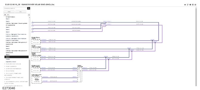
E273046

Controller Area Network (CAN)

Control Module Connections to the CAN Harness

Control modules are connected to the CAN harness either in a 'loop' or 'spur' configuration. In the 'loop' type configuration the CAN harness loops into the module (via two connector pins) and then loops out of the module (via another two connector pins). In the 'spur' type configuration, a harness spur is spliced into the main 'backbone' of the CAN harness and the module is connected to the harness spur via two connector pins.

CAN Harness Architecture

For a detailed description of the CAN Networks and architecture, refer to the relevant Description and Operation section in the Workshop Manual.

CAN Terminating Modules

If the communication Network failure procedure indicates that one or more module on one of the CAN networks (HS or MS) are failing to communicate, there are several checks that can be made. The first step is to identify if both of the CAN terminating modules on each individual CAN Bus are communicating. If both CAN terminating modules for each individual CAN Bus are communicating (identified via the Communication Network failure procedure), then it can be confirmed that the main 'backbone' of the CAN harness is complete. The main 'backbone' of the CAN harness consists of all the modules connected to the CAN harness via a 'loop' configuration and also includes the two terminating modules.

Communication with both CAN terminating modules via the Communication Network failure procedure test confirms the physical integrity of the main 'backbone' of the CAN harness (and the harness spur to the J1962 diagnostic connector). This means that there is no requirement to check the resistance of the CAN Network. This is because the standard check for 60 ohms across the CAN High and CAN Low lines will not provide any additional information regarding the physical condition of the CAN harness, beyond what has already been determined from the Communication Network failure procedure.

Non-Communication of a Terminating Module

If the Communication Network failure procedure reveals a terminating module is failing to communicate it can indicate a break in the main 'backbone' of the CAN harness. The first checks should always be to confirm the power and ground supplies to the non-communicating module are correct. Providing these are correct, the resistance between the CAN High and CAN Low lines at the J1962 connector can be checked to determine the integrity of the main 'backbone' of the CAN harness. After disconnecting the battery a reading of 120 ohms would indicate an open circuit in the main 'backbone' of the CAN harness. Alternatively, a reading of 60 ohms would indicate that there is no open circuit fault with the main 'backbone' of the CAN harness.

It is worth noting that even if one of the terminating modules is disconnected from the CAN harness, communications between the modules still connected may still be possible. Therefore communication between the manufacturer approved diagnostic system and the connected modules may also be possible.

Locating CAN Harness Open Circuits

In the case where multiple modules, including a terminating module, are failing to communicate, having first confirmed the power and ground supplies are correct, the approximate location of the open circuit can be identified from analysis of the Communication Network failure procedure results and reference to the relevant CAN network circuit diagrams. For example, if an open circuit existed in a certain position on the CAN harness, any module positioned on the Network between the J1962 connector and the open circuit should return a response during the Communication Network failure procedure. No responses would be returned from any modules past the open circuit fault in the Network.

CAN Harness 'Spur' Type Configuration Circuits

If, after the initial checks (Communication Network failure procedure using the manufacturer approved diagnostic system, and power and ground supplies to the module have been checked and confirmed as correct), a module that is connected to the CAN harness via a 'spur' type configuration is suspected of not communicating, then the physical integrity of the CAN harness 'spur' can be checked.

This is most easily undertaken by individually checking the continuity of the CAN High and CAN Low lines between the non-communicating module connector (with the module disconnected) and the J1962 diagnostic connector.

'Lost Communications' DTCs

As well as the methods described so far in this document, which can be used to determine the location of an open circuit in the CAN harness, 'Lost Communications' DTCs can also be used for this purpose. Lost communication DTCs mean that a module is not receiving CAN information from another module.

For example, if a global DTC read were to be carried out, only DTCs stored in the modules that the manufacturer approved diagnostic system could communicate with would be displayed. If there was an open circuit fault in a certain position on the CAN harness, the modules that could display DTCs would all be prior to the open circuit on the Network, and these modules should display 'Lost Communications' DTCs with all the modules located on the Network past the open circuit fault.

'Bus off' DTCs

The references to bus and its condition refer to the network concerned and the modules on that network.

If a module logs a 'Bus Off' DTC, it means that the module has detected CAN transmission errors and has disabled its own CAN transmissions and disconnected itself from the network in an attempt to allow the rest of the network to function. At this point the 'Bus Off' DTC is set. A common cause of 'Bus Off' DTCs can be a short circuit in the CAN network.

FlexRay

Control Module Connections to the FlexRay Harness

Control modules are connected to the FlexRay harness in a point to point and daisy chain type configuration. The Anti-lock Brake System Control Module (ABS) and Powertrain Control Module (PCM) are connected via a point to point connection. The Transmission Control Module (TCM) and Transfer Case Control Module (TCCM) (where fitted) are connected via the daisy chain connection (when a TCCM is fitted, if not the TCM would also be a point to point connection). In the daisy chain type configuration the FlexRay harness enters the module (via two connector pins) and then exits the module (via another two connector pins), as shown in the figure below.
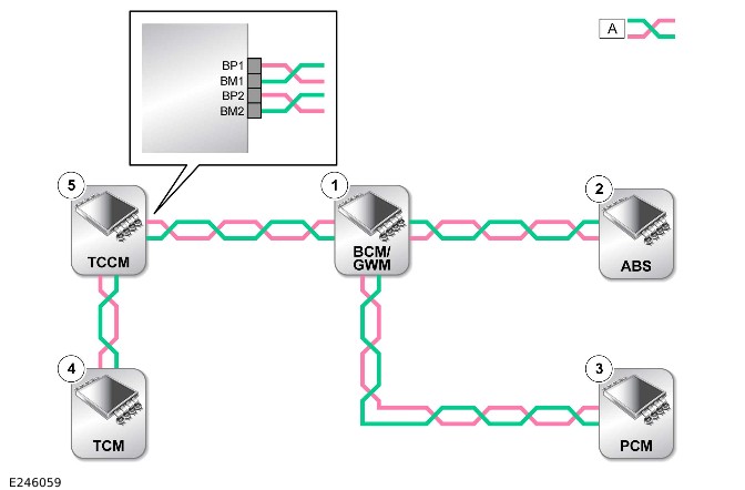
E246059

A=FLEXRAY NETWORK

ITEMDESCRIPTION
1Body Control Module (BCM)/Gateway Module (GWM)
2Anti-lock Brake System Control Module (ABS)
3Powertrain Control Module (PCM)
4Transmission Control Module (TCM)
5Transfer Case Control Module (TCCM) where fitted

FlexRay Harness Architecture

For a detailed description of the FlexRay harness architecture, refer to the relevant Description and Operation section in the workshop manual.

FlexRay Communication Check

If a control module is suspected of non-communication, a communication check available on the Jaguar Land Rover approved diagnostic equipment can be used to confirm if communication is possible between the control modules on the vehicle with the Jaguar Land Rover approved diagnostic equipment. The results from the test can be used to determine if either a single module or multiple modules are failing to communicate. Refer to the pinpoint test below for the steps to diagnose a FlexRay network fault.

FlexRay Network Integrity

If the communication check indicates that one or more modules on the FlexRay network are failing to communicate, there are several checks that can be made. The first step is to identify if the terminating modules on the FlexRay network are communicating, the terminating modules (which are required at both ends of each branch of the network) are located within the Gateway Module (GWM), the Anti-lock Braking System Control Module (ABS), the Powertrain Control Module (PCM), and the Transmission Control Module (TCM). If the terminating modules for the FlexRay network are communicating (identified via the communication check), then it can be confirmed that the FlexRay harness is complete.

Communication with the FlexRay terminating modules via the communication check confirms the physical integrity of the FlexRay harness. This means that there is no requirement to check the resistance of the FlexRay network. This is because the standard check for 90-100 ohms across the BP (Bus Plus) and BM (Bus Minus) will not provide any additional information regarding the physical condition of the FlexRay harness, beyond what has already been determined from the communication check. If however a communication check reveals a terminating module is failing to communicate it can indicate a break in the FlexRay harness. The first checks should always be to confirm the power and ground supplies to the non-communicating module are correct. Providing these are correct, details for how to check the integrity of a terminating module can be found below.

Checking Terminating Module Integrity

Firstly disconnect the module power supply, then measure the resistance between the module FlexRay Bus Plus (BP) and Bus Minus (BM) terminals. The expected resistance for a terminating module is between 90 and 100Ω any reading outside of this parameter may indicate module failure.
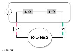
E246060

ITEMDESCRIPTION
1Module

Checking Non-Terminating Module Integrity

Firstly disconnect the module power supply, then measure the resistance between the FlexRay terminals in the order listed below:

1. Bus Plus (BP) 1 and Bus Minus (BM) 1, the expected resistance for a non-terminating module is approximately 2.6kΩ

2. Bus Plus (BP) 2 and Bus Minus (BM) 2, the expected resistance for a non-terminating module is approximately 2.6kΩ

3. Bus Plus (BP) 1 and Bus Plus (BP) 2, the expected resistance for a non-terminating module is less than 2Ω

4. Bus Minus (BM) 1 and Bus Minus (BM) 2, the expected resistance for a non-terminating module is less than 2Ω

Any reading outside of these parameters may indicate a module failure.
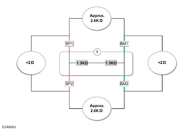
E246061

ITEMDESCRIPTION
1Module

Locating FlexRay Harness Open Circuits

In the case where multiple modules, including the terminating modules, are failing to communicate, having first confirmed the power and ground supplies are correct, the approximate location of the open circuit can be identified from analysis of the communication check results. No responses would be returned from any modules past the open circuit fault in the network (please refer to the diagram below). Any short circuit, open circuit, or high resistance faults detected on the FlexRay harness should be repaired in accordance with the Jaguar Land Rover approved wiring harness repair procedure maintaining 90 to 100 ohms across the FlexRay network, maintaining the wire twist rate (20mm+/-2mm for one full 360° twist), using no more than of five in-line connectors on each branch of the FlexRay network. For further information refer to section 418-02 Wiring Harness, Description and operation, in the workshop manual.
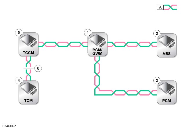
E246062

A=FLEXRAY NETWORK

ITEMDESCRIPTION
1Body Control Module (BCM)/Gateway Module (GWM)
2Anti-lock Brake System Control Module (ABS)
3Powertrain Control Module (PCM)
4Transmission Control Module (TCM) located after the open circuit in the FlexRay network causing "Lost Communication" DTCs with other modules on the FlexRay network
5Transfer Case Control Module (TCCM) (where fitted) prior to the FlexRay network open circuit showing "Lost Communication" DTCs
6FlexRay network open circuit

FlexRay 'Bus off' DTCs

The references to bus and its condition refer to the network concerned and the modules on that network.

If a module logs a 'Bus off' DTC, it means that the network has detected FlexRay transmission errors and has disabled its own FlexRay transmissions and disconnected itself from the network in an attempt to allow the rest of the network to function. At this point the 'Bus off' DTC is set. A common cause of 'Bus off' DTCs can be a short circuit in the FlexRay network. Any short circuit, open circuit, or high resistance faults detected in the FlexRay harness should be repaired in accordance with the Jaguar Land Rover approved wiring harness repair procedure maintaining 100 ohms across the FlexRay network and also maintaining the wire twist rate.

FlexRay Pinpoint Tests

PINPOINT TEST A : CHECKING FLEXRAY INTEGRITY
A1: FLEXRAY NETWORK INTEGRITY
TEST CONDITIONSDETAILS/RESULTS/ACTIONS
1 Firstly check the FlexRay network integrity.
Connect the Jaguar Land Rover approved diagnostic equipment to the vehicle and perform the Communication Network failure procedure. Has a fault been identified on the FlexRay network? Yes No fault has been detected within the FlexRay network. No GO to A2.
A2: TERMINATING MODULE CONNECTION
TEST CONDITIONSDETAILS/RESULTS/ACTIONS
1 Termination module integrity check.
Refer to the FlexRay communication check and confirm whether the termination modules are communicating. Yes The termination modules are communicatingGO to A3. No The termination modules are not communicatingGO to A4.
A3: NON-TERMINATING MODULE CONNECTION
TEST CONDITIONSDETAILS/RESULTS/ACTIONS
1 Non-terminating module integrity check.
Using the Jaguar Land Rover approved diagnostic equipment and the circuit diagrams, check the non-communicating module power and ground supplies, are these correct? Yes Using the Jaguar Land Rover approved diagnostic device, check the DTCs and refer to the relevant DTC index and perform the suggested corrective actions, module replacement may be advised. No Refer to the circuit diagrams and check the module power and ground supply circuits for short circuit to power, short circuit to ground, open circuit, or high resistance. Repair the circuit as required and retest.
A4: TERMINATING MODULE POWER SUPPLY CHECK
TEST CONDITIONSDETAILS/RESULTS/ACTIONS
1 Module power supply and ground check.
Using the Jaguar Land Rover approved diagnostic equipment and circuit diagrams, check the communicating termination module power and ground supplies, are these correct? Yes GO to A5. No Refer to the circuit diagrams and check the termination module power and ground supply circuits for short circuit to power, short circuit to ground, open circuit, or high resistance. Repair the circuit as required and retest.
A5: FLEXRAY NETWORK RESISTANCE CHECK
TEST CONDITIONSDETAILS/RESULTS/ACTIONS
1 Check the resistance of the FlexRay network.
Are the results between 90-100 ohms? Yes Using the Jaguar Land Rover approved diagnostic equipment, check the DTCs and refer to the relevant DTC index and perform the suggested corrective actions, module replacement may be advised. No Refer to the electrical circuit diagrams and check the FlexRay harness for open circuit or high resistance. Repair the circuit as required and retest.

BroadR-Reach® Ethernet

The infotainment control modules use the BroadR-Reach® Ethernet network connection to communicate, for a detailed description of the BroadR-Reach® Ethernet network please refer to the relevant Description and Operation section of the workshop manual. The BroadR-Reach® Ethernet network is constantly monitored by the modules connected, any fault within the BroadR-Reach® Ethernet network raises a DTC in the associated module. For any related diagnostics to the BroadR-Reach® Ethernet network, please check for DTCs and refer to the relevant DTC index.

DTC Index

For a list of Diagnostic Trouble Codes (DTCs) that could be logged on this vehicle, please refer to Section 100-00. REFER to: Diagnostic Trouble Code Index - DTC: Body Control Module (100-00 General Information, Description and Operation).


Body Control Module/Gateway Module Assembly (G2431322)

REMOVAL AND INSTALLATION

  • 86.80.04
  • Body Control Module (BCM) / Gateway Module (GWM) Assembly - Renew
  • All Derivatives
  • 0.50
  • USED WITHINS

General Equipment

Equipment name
Jaguar Land Rover approved diagnostic equipment

Removal

NOTES:

  • If a new Body Control Module/Gateway Module (BCM/GWM) is installed, a new Remote Function Actuator (RFA) must also be installed. This step is only required for vehicles that are 15MY or later. This step is not required for North American Specification (NAS) vehicles. Use the approved Jaguar Land Rover (JLR) diagnostic equipment to configure the new RFA.
  • Make sure all of the keys are present before this procedure is completed.
  • A maximum of 8 remote transmitters and activity keys can be programed to the BCM/GWM. Programming for all remote transmitters and activity keys must be completed at the same time.
  • This procedure contains some variation in the illustrations depending on the vehicle specification, but the essential information is always correct.
  • This procedure contains illustrations showing certain components removed to provide extra clarity.
  1. If a new Body Control Module/Gateway Module (BCM/GWM) is installed, use the approved Jaguar Land Rover diagnostic equipment to download the stored data.General Equipment: Jaguar Land Rover approved diagnostic equipment
  2. Disconnect the startup battery ground cable.Refer to: 12V System Disconnect and Connect (414-00 Battery and Charging System - General Information, General Procedures).
  3. Remove the Passenger Junction Box (PJB).Refer to: Passenger Junction Box (418-00 Module Communications Network, Removal and Installation).
  4. E255840
    • Disconnect the 9 electrical connectors.
    • Remove the 2 nuts.
    • Release the BCM/GWM from the 2 grommets.
    • Remove the BCM/GWM.

Installation

    • Install the Body Control Module/Gateway Module (BCM/GWM) to the 2 grommets.
    • Install and tighten the 2 nuts.Torque: 10Nm
    • Connect the 9 electrical connectors.


Wiring Harness (G4394130)

DESCRIPTION AND OPERATION

1. Introduction

Use the table below to identify the type of wiring harness or section.

Harness TypeRepair Y/NCable repairsConnector repairsLimitationsSectionComments
Controller Area Network (CAN) (speed up to 500 kbps)YYYNone2.1.1 
FlexRayYYYNone2.1.2 
BroadR-Reach®YYYNone2.1.3 
Radio Frequency (RF) harnessYYYNone2.2 
Local Interconnect Network (LIN) busYYYNone2.3 
Co-axialYYYNone2.4 
National Television System Committee (NTSC)YYYNone2.5Video signals used on NAS vehicles.
Low Voltage Differential Signal (LVDS)YYYNone2.6Video signals used on ROW vehicles
Serial communicationYYYNone2.7 
Pulse Width Modulated (PWM)YYYNone2.8 
Universal Serial BusYYYNone2.9 
Electric Vehicle (EV) High voltageNNN 2.18Currently no repairs to orange colored High Voltage (HV) cables
EV High voltage 3 PhaseNNN 2.18Currently no repairs to orange colored HV cables
48V Mild Hybrid Electric Vehicle (MHEV)NNN 2.19Currently no repairs to 48V MHEV cables (light Blue)
Automotive Pixel Link 2(APIX2)YYY 2.10 
High Voltage Interlock LoopYYY 2.11 
Battery Monitoring Sensor (BMS) fusible linkNNN>td rowspan="1">2.12 
Media Oriented System Transport (MOST)/fiber opticYYY 2.13 
Air Suspension OverlayYYY 2.14 
Supplementary Restraint System (SRS)YYY 2.15 
Pedestrian protectionNNN  Harness/components must be replaced
Anti-Lock Brake System Control Module (ABS)YYY  ABS circuits can be repaired with overlays.
12V MHEVYYY 2.16 
Low Voltage 3 PhaseYYYY2.17 

Repairs

Section TitleSectionComments
Harness repairs2 
Electrical connector probing3.1 
Pin drag test3.2Not allowed
Grommets3.3 
Cable clips3.4 
Wiring harness repairs4 
Approved Electrical Wiring Harness Repair Methods4.1 
Splice repairs4.2 
Harness repair Procedure4.3 
Electrical Wiring Harness Repair Components4.4 
Wiring Harness repair4.5 

2. Harness repairs

2.0 General procedures

The following procedures must be followed for all harness repairs.

2.01 Approved probing and repair methods

The purpose of this document is to identify the approved methods to promote an effective and efficient diagnosis and minor repair to the:

  • Permitted electrical wiring harnesses, connectors and cables
    • See Electrical Wiring Harness Repair - section 4.1
  • Media Oriented System Transport (MOST) network harnesses, connectors and fiber optic cables
    • See MOST Network Harness Repair - section 2.13.

2.02 Replacement Repair Equipment

The repair processes in the following information identifies specific repair equipment needed to complete a repair to the required standard.

Replacement repair equipment can be ordered from the equipment workshop website:

http://jlrequipment.service-so...

2.1 Twisted wire harnesses

It is important to make sure that the number of turns over the repair length is counted at the start of the repair. Make sure that the same number of turns are reintroduced before installing the terminals into the connector. If the original number of turns cannot be reintroduced on a twisted wire, the following dimensions must not be exceeded.

It is important to maintain the correct number of twists per meter. It is suggested that the number of twists are counted over a set length. For example, if there are 50 twists/m, count the number of twists over 10cm (3.94 inches) of a representative section of the cable. This is to confirm that the number of twists is enough.

For a cable that has 50 twists/m, each twist is taking 2 cm (0.79 inches). Therefore, in 10 cm there will be at least 5 complete twists to consider that the twisting is acceptable. It is also important to compare the rest of the cable to confirm it visually has the same twisting.

The length of an untwisted part of a harness includes both ends. The image below shows untwisted sections and an indication of 1 twist.
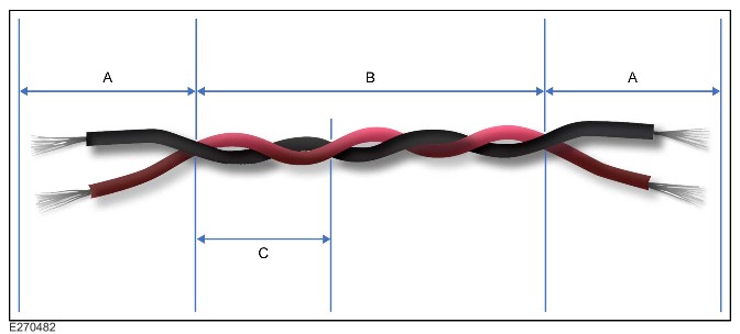
E270482

ItemDescription
AUntwisted section
BTwisted section
C1 twist

2.1.1 Controller Area Network (speed up to 500 kbps)

The following details the repairs for a CAN (speed up to 500 kbps) harness. The CAN has twisted wires.

For a CAN (speed up to 500 kbps) harness, the maximum length of untwisted wire is:

  • 1x untwisted section (terminating connector repair) - 50 mm (2.0 inch)
  • 2x untwisted section (inline splice connector repair) - 100 mm (3.9 inch).

Follow the repair procedure as in section 4 of this document.

2.1.2 FlexRay

The following details the repairs for a FlexRay harness. The FlexRay has twisted wires.

For a FlexRay harness, the maximum length of untwisted wire is:

  • 1x untwisted section (terminating connector repair) - 30 mm (1.1 inch)
  • 2x untwisted section (inline splice connector repair) - 60 mm (2.3 inch).

Follow the repair procedure as in section 4 of this document.

2.1.3 BroadR-Reach®

The following details the repairs for a BroadR-Reach® harness. The BroadR-Reach® has twisted wires.

For a BroadR-Reach® harness, the maximum length of untwisted wire is:

  • 1x untwisted section (terminating connector repair) - 25 mm (1.0 inch)
  • 2x untwisted section (inline splice connector repair) - 50 mm (2.0 inch).

Follow the repair procedure as in section 4 of this document.

2.2 Radio Frequency harness

Follow the repair procedure as in section 4 of this document.

2.3 Local Interconnect Network bus

Follow the repair procedure as in section 4 of this document.

2.4 Co-axial

Usually a connection from an antenna to an antenna amplifier.

Follow the repair procedure as in section 4 of this document.

2.5 National Television System Committee

National Television System Committee (NTSC) is a video standard for NAS vehicles

Follow the repair procedure as in section 4 of this document.

2.6 Low Voltage Differential Signal

Low Voltage Differential Signal (LVDS) is a video signal for ROW vehicles.

Follow the repair procedure as in section 4 of this document.

2.7 Serial communication

Follow the repair procedure as in section 4 of this document.

2.8 Pulse Width Modulation

Follow the repair procedure as in section 4 of this document.

2.9 Universal Serial Bus

Follow the repair procedure as in section 4 of this document.

2.10 Automotive Pixel Link 2

Audio/video connection. APIX2 is used for signals between the Infotainment system and the and >span class="acronym">Head Up Display (HUD).

Follow the repair procedure as in section 4 of this document.

2.11 High Voltage Interlock Loop

A safety system in EV and Plug-in Hybrid Electric Vehicle (PHEV). prevents the system being powered up if a HV cable or harness is disconnected.

Follow the repair procedure as in section 4 of this document.

2.12 Battery Monitoring System Fusible Link

NOTE:

Under no circumstances is a piece of standard wire to be used to effect the fusible link repair.

The BMS fusible link must be replaced, repairs are not to be performed on the fusible link.

If the fusible link ruptures then the source of the fault must be diagnosed and rectified first. The fusible link is then to be replaced using the authorized service repair kit (part number LR057241). The fusible link must be spliced into the affected lead/circuit using the approved sealed inline splice repair technique. See section 4 wire only repair procedure.

Refer to the Electronic Parts Catalogue (EPC) for available components. Stock check required.

2.13 Media Oriented System Transport Network Harness Repair

The MOST connector(s) have an anti-backout device which prevents the contact from being released from the connector. The anti-backout device must be released before attempting to remove the terminal from the connector. The anti-backout devices require a special tip to release the device. Refer to the Electrical Reference Library (ERL) for the correct tool(s) to use.

The illustration shows an example of a common style of extraction tool being used on a MOST connector(s). Care must be exercised to avoid further damage when removing the terminals from the connector.

CAUTIONS:

  • Before releasing the fiber optic cable from the connector housing, mark the IN/OUT assignment of the fiber optic cable.
  • Make sure a protective cap is installed on all disconnected MOST connectors and fiber optic cables. The protective cap prevents contamination and damage to the exposed end faces of the fiber optic cable.

MOST Connector Terminal Extraction
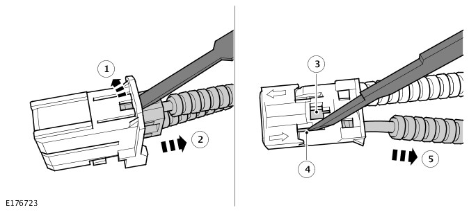
E176723

MOST Harness Repair Process
E176550

  1. Confirm the length of fiber optic conductor lead required to create a new fiber optic cable. Cut the fiber optic conductor lead to the required length using the fiber optic cable cutter.

E176551

  1. Open the fiber optic conductor stripper jaws and insert the fiber optic conductor lead up to the edge of the jaws.

E176552

  1. Close the fiber optic conductor stripper jaws (1) and carefully pull the fiber optic conductor lead (2) to remove the protective casing.

E176558

    NOTE:

    Make sure the protective casing of the fiber optic conductor lead sits against the fiber optic conductor cutter jaw stop.

  1. Open the fiber optic conductor stripper jaws and insert the fiber optic conductor lead fully into the fiber optic conductor cutter slot. Close the fiber optic conductor stripper jaws.

E176553

  1. Pull the fiber optic conductor core cutter lever (1) to move the cutting wheel (2) and cut the fiber optic conductor core.
    NOTE:

    The end of the fiber optic core has now been prepared for the installing of a brass contact.

  1. Open the fiber optic conductor stripper jaws and remove the fiber optic conductor lead.
    NOTE:

    Make sure the fiber optic conductor core end remains clean at all times.

  1. Place fiber optic conductor stripper and fiber optic conductor lead to 1 side.
  1. Open the fiber optic conductor contact pliers and reposition the conductor contact locking arm to the open position.

E176554

    NOTE:

    Make sure the locking arm locates on the retaining pin when in the closed position.

  1. Insert a conductor contact (1) into the fiber optic conductor contact crimping jaws and reposition the conductor contact locking arm to the closed position (2).

E176555

  1. Insert the prepared end of the fiber optic conductor lead into the conductor contact.
    CAUTION:

    Make sure the fiber optic conductor lead is pushed in and held against the spring loaded stop when closing the fiber optic conductor contact pliers. This sets the core to the correct depth in the brass connector. Failure to follow this instruction may result in the fiber optic conductor cable malfunctioning.

  1. Push the fiber optic conductor lead fully into the conductor contact and close the fiber optic conductor contact pliers.
  1. Open the fiber optic conductor contact pliers and reposition the conductor contact locking arm to the open position.
  1. Remove the fiber optic conductor cable from fiber optic conductor contact pliers.
  1. Place fiber optic conductor contact pliers to 1 side.

E176556

    CAUTION:

    Make sure the conductor contact has been correctly installed to the fiber optic conductor core. Failure to follow this instruction may result in the fiber optic cable malfunctioning.

    NOTES:
    • The fiber optic core end must sit 0.01 mm (0.00039 inch) to 0.1 mm (0.0039 inch) below the height of the conductor contact end.
    • Make sure the fiber optic conductor contact remains clean at all times.
  1. Visually inspect the conductor contact for correct installation to the fiber optic core.
      • Make sure the conductor contact has been visibly crimped at 4 points.
      • Pull the conductor contact by hand to make sure it is secure.
      • Make sure the end of the fiber optic core sits below the height of the new conductor contact end.
      • Install a fiber optic conductor contact protective cap.
  1. Repeat steps 2 to 15 and install a conductor contact to the opposite end of the fiber optic conductor cable.
  1. Measure between the conductor contact ends of the new fiber optic cable. Using a suitable tool cut a length of new protective corrugated tubing to the required length.

E176557

  1. Install the fiber optic cable into the corrugated tubing.
    1. Place the fiber optic cable inside the fiber optic conductor cable installation pliers.
    2. Insert the fiber optic conductor cable installation pliers into the corrugated tubing.
    3. Move the fiber optic conductor cable installation pliers down the length of corrugated tubing and install the fiber optic cable.

2.13.1 MOST Network Harness Repair

If a fiber optic cable is damaged, it must not be repaired and must be replaced with a new cable.

Replacement fiber optic cables can only be made using the approved repair equipment and components.

The approved repair kit contains the specially designed fiber optic conductor strippers. The cutters are used to prepare 2.3 mm (0.09 inch) fiber optic cable for the installation of the brass fiber optic conductor contact. The fiber optic conductor contact crimping pliers must then used be used to crimp the brass contact to the fiber optic conductor core. The approved crimping pliers supply the appropriate pressure to the brass contact to make a secure contact, but not damage the conductor core.

The cut face of the fiber optic core must be protected from damage and contamination at all times.

CAUTION:

Fiber optic cables have a maximum bending radius 25 mm (0.98 inch) and must not be kinked or excessively bent.

The performance of fiber optic cables is very dependant upon the quality of the cut surface at connections and to the bending radius of the cables.

2.13.2 MOST Harness Repair Components and Tools

List of Parts

NOTE:

Repair components can be ordered through the Jaguar Land Rover (JLR) parts ordering system.

DescriptionPart NumberQuantity
Fiber Optic Conductor Lead418-6761
Fiber Optic Conductor Contact418-67720
Fiber Optic Conductor Contact Protective Cap418-67820
Fiber Optic Conductor Lead Connector - Inner418-67910
Fiber Optic Conductor Lead Connector - Outer418-68010
MOST Module Protective Cap418-68120
Fiber Optic Conductor Lead Connector Protective Cap418-68220

Fiber Optic Conductor Stripper
E176559

Fiber Optic Conductor Stripper Jaw Positions
E176549

1Fiber Optic Cable Cutter
2Fiber Optic Cable Insulation Stripper
3Fiber Optic Core Cutter

Fiber Optic Core Cutter Locking Screw
E176547

The fiber optic core cutter has a locking screw to protect the cutter wheel when in transit or not in use. A hexagonal key is supplied in the MOST repair kit to release the locking screw.

NOTE:

Tighten the transportation locking screw after use.

Fiber Optic Core Cutter Remaining Cut Indicator
E176548

The fiber optic core cutter can be used for approximately 1260 cuts. The indicator line on the remaining cut indicator window only becomes visible when the fiber optic core cutter has 150 cuts or below available.

NOTE:

When the fiber optic core cutter has reached the maximum allowed cuts, the cutter will become locked and the fiber optic conductor stripper must then be renewed.

Before using the fiber optic conductor core cutter, make sure it has enough cuts remaining to complete the repair process by viewing the remaining cut indicator.

Fiber Optic Conductor Contact Crimping Pliers
E176560

A small amount of effort is required to operate the fiber optic conductor contact crimping pliers and secure a fiber optic conductor contact to the fiber optic conductor core.

The new fiber optic conductor contact is placed into the cramping mechanism in the head of the pliers. The locking arm is repositioned to hold the conductor contact securely in position. The locking arm must locate on to the retaining pin.

The prepared end of the fiber optic core is then inserted into the new conductor contact.

The fiber optic core and conductor contact must be pushed and held against the spring pressure in the cramping mechanism. The grips of the fiber optic conductor contact crimping pliers are then be closed, cramping the conductor contact to the conductor core.

NOTES:

  • Only use the approved fiber optic conductor contact crimping pliers to cramp a new conductor contact.
  • A conductor contact must only be cramped when using the fiber optic conductor contact crimping pliers.

The cramping mechanism inside the head applies the appropriate pressure to the conductor contact at 4 points. This makes a secure contact and does not damage the conductor core.

E176556

When the new conductor contact has been cramped to the fiber optic core do the following. Make sure the fiber optic core end sits 0.01 mm (0.00039 inch) to 0.1 mm (0.0039 inch) below the height of the conductor contact end.

NOTE:

Make sure the fiber optic conductor lead contact remains clean and protected at all times. Install a fiber optic conductor contact protective cap.

MOST Repair Tools

NOTE:

Replacement repair equipment can be ordered from the equipment workshop website; refer to the Replacement Repair Equipment in the Introduction section.

DescriptionPart NumberQuantity
MOST Repair Kit418-6731
Fiber Optic Conductor Stripper418-6741
Fiber Optic Conductor Contact Crimping Pliers418-6751
Fiber Optic Conductor Lead Installation Pliers418-6832

2.13.3 MOST Harness Repair Procedure

The MOST connector(s) have an anti-backout device which prevents the contact from being released from the connector. The anti-backout device must be released before attempting to remove the terminal from the connector. The anti-backout devices require a special tip to release the device. Refer to the ERL for the correct tool(s) to use.

The illustration shows an example of a common style of extraction tool being used on a MOST connector(s). Care must be exercised to avoid further damage when removing the terminals from the connector.

CAUTIONS:

  • Before releasing the fiber optic cable from the connector housing, mark the IN/OUT assignment of the fiber optic cable.
  • Make sure a protective cap is installed on all disconnected MOST connectors and fiber optic cables. The protective cap prevents contamination and damage to the exposed end faces of the fiber optic cable.

MOST Connector Terminal Extraction
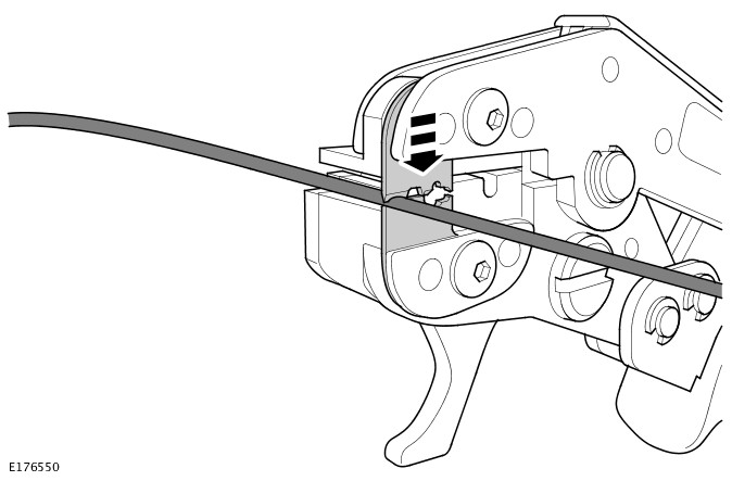
E176723

MOST Harness Repair Process
E176550

  1. Confirm the length of fiber optic conductor lead required to create a new fiber optic cable. Cut the fiber optic conductor lead to the required length using the fiber optic cable cutter.
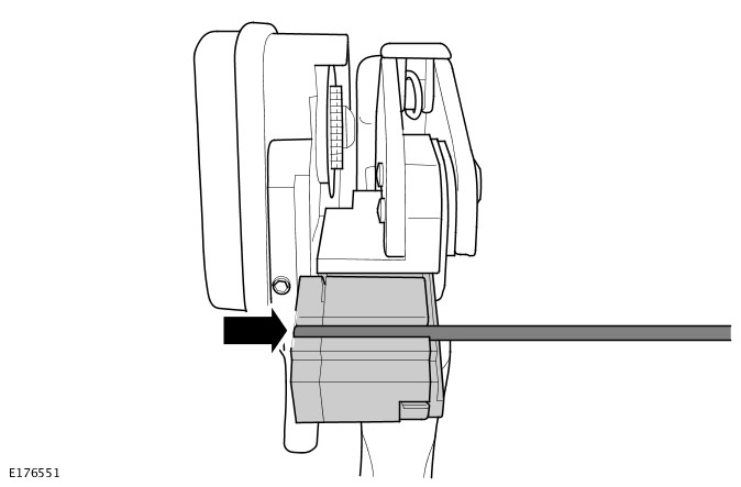
E176551

  1. Open the fiber optic conductor stripper jaws and insert the fiber optic conductor lead up to the edge of the jaws.
E176552

  1. Close the fiber optic conductor stripper jaws (1) and carefully pull the fiber optic conductor lead (2) to remove the protective casing.
E176558

    NOTE:

    Make sure the protective casing of the fiber optic conductor lead sits against the fiber optic conductor cutter jaw stop.
  1. Open the fiber optic conductor stripper jaws and insert the fiber optic conductor lead fully into the fiber optic conductor cutter slot. Close the fiber optic conductor stripper jaws.

E176553

  1. Pull the fiber optic conductor core cutter lever (1) to move the cutting wheel (2) and cut the fiber optic conductor core.
    NOTE:

    The end of the fiber optic core has now been prepared for the installing of a brass contact.

  1. Open the fiber optic conductor stripper jaws and remove the fiber optic conductor lead.
    NOTE:

    Make sure the fiber optic conductor core end remains clean at all times.

  1. Place fiber optic conductor stripper and fiber optic conductor lead to 1 side.
  1. Open the fiber optic conductor contact pliers and reposition the conductor contact locking arm to the open position.
E176554

    NOTE:

    Make sure the locking arm locates on the retaining pin when in the closed position.
  1. Insert a onductor contact (1) into the fiber optic conductor contact crimping jaws and reposition the conductor contact locking arm to the closed position (2).

E176555

  1. Insert the prepared end of the fiber optic conductor lead into the conductor contact.
    CAUTION:

    Make sure the fiber optic conductor lead is pushed in and held against the spring loaded stop when closing the fiber optic conductor contact pliers. This sets the core to the correct depth in the brass connector. Failure to follow this instruction may result in the fiber optic conductor cable malfunctioning.

  1. Push the fiber optic conductor lead fully into the conductor contact and close the fiber optic conductor contact pliers.
  1. Open the fiber optic conductor contact pliers and reposition the conductor contact locking arm to the open position.
  1. Remove the fiber optic conductor cable from fiber optic conductor contact pliers.
  1. Place fiber optic conductor contact pliers to 1 side.
E176556

    CAUTION:

    Make sure the conductor contact has been correctly installed to the fiber optic conductor core. Failure to follow this instruction may result in the fiber optic cable malfunctioning.

    NOTES:
    • The fiber optic core end must sit 0.01 mm (0.00039 inch) to 0.1 mm (0.0039 inch) below the height of the conductor contact end.
    • Make sure the fiber optic conductor contact remains clean at all times.
  1. Visually inspect the conductor contact for correct installation to the fiber optic core.
      • Make sure the conductor contact has been visibly crimped at 4 points.
      • Pull the conductor contact by hand to make sure it is secure.
      • Make sure the end of the fiber optic core sits below the height of the new conductor contact end.
      • Install a fiber optic conductor contact protective cap.
  1. Repeat steps 2 to 15 and install a conductor contact to the opposite end of the fiber optic conductor cable.
  1. Measure between the conductor contact ends of the new fiber optic cable. Using a suitable tool cut a length of new protective corrugated tubing to the required length.
E176557

  1. Install the fiber optic cable into the corrugated tubing.
    1. Place the fiber optic cable inside the fiber optic conductor cable installation pliers.
    2. Insert the fiber optic conductor cable installation pliers into the corrugated tubing.
    3. Move the fiber optic conductor cable installation pliers down the length of corrugated tubing and install the fiber optic cable.

2.14 Air suspension overlay

NOTES:

  • This repair applies to L320/LS, L405/LG and L494/LW models only.
  • Some variation in the illustrations may occur, but the essential information is always correct.

If after diagnosis the height sensor requires replacement and the area of wiring damage is localized to the height sensor connector, this overlay harness must be used,

1. Disconnect the battery ground cable. For additional information, refer to Workshop manual section 414-00, Specifications - Battery Disconnect/Connect.

2. Disconnect the damaged height sensor electrical connector.
E78443

3. Unclip a sufficient length of the wiring harness to allow easy access during the repair.
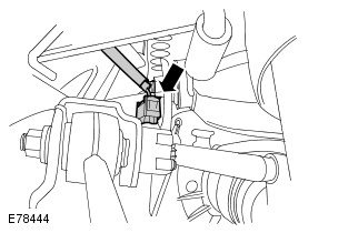
E78444

4. Remove the wiring harness insulation as required.

NOTES:

  • It is advisable to cut only 1 of the wires at a time and to stagger each joint to allow easier insulation.
  • The colours of the overlay harness may vary.

5. Cut the wire on the vehicle harness leading to cavity 1 of the height sensor connector in a suitable position. Then remove 10 mm (0.39 inch) of insulation. For connector location and pin identification, refer to the relevant connector:

  • L320 - C1696/7/8/9
  • L405/L494 - C1CD10/11/12/13

In the Connector Details section of the relevant Electrical Library.
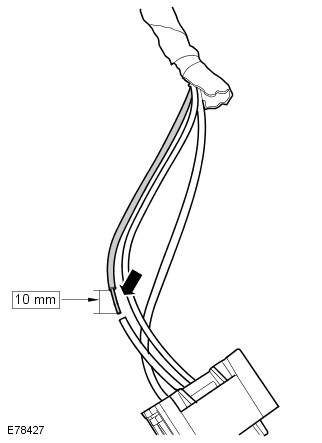
E78427

6. Slide over this wire a section of heat shrink sleeving.
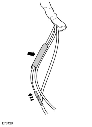
E78428

7. Using the inline connector supplied and the correct crimping tool set to the correct jaw size from the harness repair kit, crimp the connector to the wire.

NOTE:

The overlay harness must be cut so that there is no additional length added to the overall length after repair.

8. Select the appropriate wire on the overlay harness that also goes to cavity 1 of the new connector. Cut the wire to the correct length and remove 10 mm (0.39 inch) of insulation.
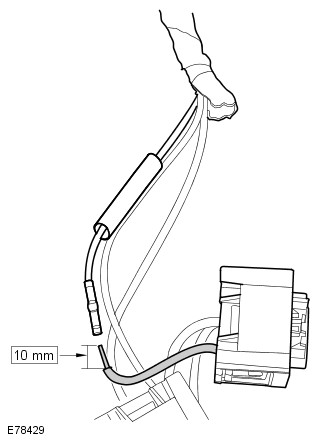
E78429

9. Insert the overlay wire into the connector and crimp in place.

CAUTION:

Care must be taken when using the hot air applicator to avoid damage to surrounding areas.

10. Slide the heatshrink over the connector and using a hot air applicator carefully apply the heat until the glue appears at both ends.

E78430

11. Do the same process for the wires in cavities 4 and 5 of the connector. For connector location and pin identification, refer to the relevant connector:

  • L320 - C1696/7/8/9
  • L405/L494 - C1CD10/11/12/13

In the Connector Details section of the relevant Electrical Library.

12. Discard the damaged connector/section of the harness.

13. Add suitable harness repair tape to the repaired area to within 10 mm (0.39 inch) of the new connector to complete the repair.
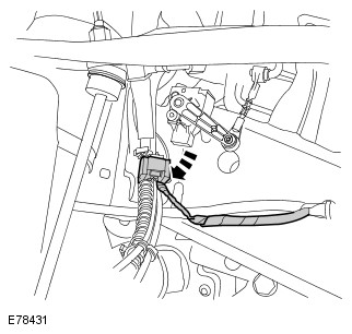
E78431

14. Correctly route/secure the harness and connect the new connector to the height sensor.

15. Connect the battery ground cable. For additional information, refer to Workshop manual section 414-00, Specifications - Battery Disconnect/Connect.

16. Clear any Diagnostic Trouble Codes (DTC) set in the Chassis Control Module (CHCM) using JLR approved diagnostic equipment and confirm correct operation of the system.

2.15 Supplementary Restraint System

WARNING:

Do not use any vehicle with damage to the supplementary restraint system components or wiring harness.

CAUTION:

All supplementary restraint system wiring harness repairs must be completed using the recommended pre-terminated leads, overlays and the approved repair kit only.

The wiring used for a SRS firing circuit repair must be 0.5 mm² (0.00078 inch²) cross sectional area. Replace Both the affected male and female terminals in the connector using pre-terminated leads. Installation of SRS connectors, cut the wiring harness at a suitable point as close as possible to the damaged connector (destroy the removed connector). Identify the correct new connector from the SRS firing circuit wiring harness repair kit or recommended overlay and cut to a suitable length. Install to the SRS firing circuit wiring harness using the connecting splices supplied and a replaced pre-terminated lead which can be identified from the ERL wire chart information.

Follow the repair procedure detailed above, taking into account the staggering of connecting splices and the number of twists. The whole repair must then be covered with yellow heat shrink sleeve supplied to act as SRS firing circuit wiring repair location/identification. The repair authentication label must be completed by the authorized technician conducting the repair and approved by their supervisor. The label must then be installed around the harness adjacent to or at a suitable point as close as possible to the location of the repair.

Care and neatness are essential requirements in making a perfect repair.

2.16 12V Mild Hybrid Electric Vehicle

Follow the repair procedure as in section 4 of this document.

2.17 Low Voltage 3 Phase

Follow the repair procedure as in section 4 of this document.

2.18 High Voltage cables and harnesses

Currently there are no repairs allowed to the HV cables and harnesses. These cables and harnesses have an ORANGE covering.

If a HV battery cable or harness is damaged, it must be replaced, not repaired.

2.19 Mild Hybrid Electric Vehicle

Currently there are no repairs allowed to the MHEV cables and harnesses. These cables and harnesses have an LIGHT BLUE covering.

If a 48V MHEV battery cable or harness is damaged, it must be replaced, not repaired.

3. Testing

3.1 Electrical connector probing

The following sections identify the approved method for electrical connector probing.

3.11 Electrical Connector Probing

Only 2 methods of electrical connector probing are allowed.

Method 1. Probing at the rear of unsealed electrical connectors (see illustration E190832).

Method 2. Probing on the conductor crimp of an extracted terminal (see illustration E190928).

  • The conductor crimp is the portion crimped to the non-insulated wire.
  • This method may be used on sealed or unsealed connectors, but method 1 is preferred for unsealed connectors.

CAUTIONS:

  • A suitable sized probe must be used. If the probe is larger than the electrical connector aperture, then damage to the electrical connector will occur.
  • The probe must only be inserted into the rear of the electrical connector for a distance sufficient to contact the terminal.
  • Take care not to bend or distort any part of the metal terminal wire crimp area with the probe.
  • Before extracting any terminals, refer to the Electrical Connector Terminal Extraction and Extraction Tools sections of this document for more information.
  • Probing must not be done on: either the connector contact area or the portion of the terminal that is crimped to the insulated part of the wire.
  • Make sure the terminal is correctly and securely located in the electrical connector after re-installation.
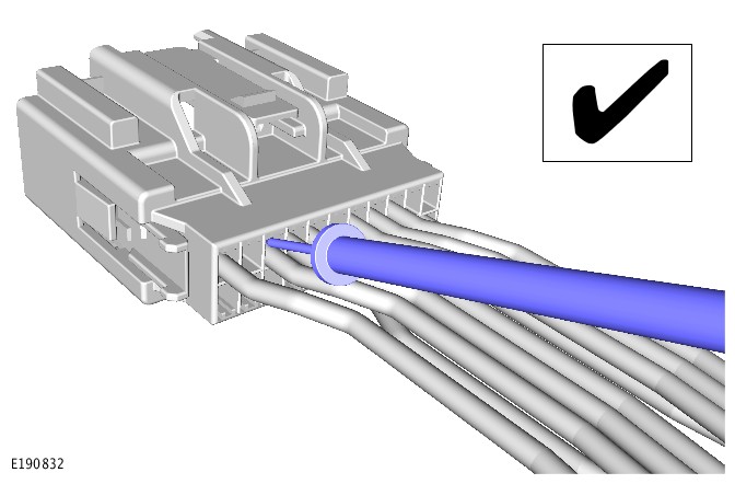
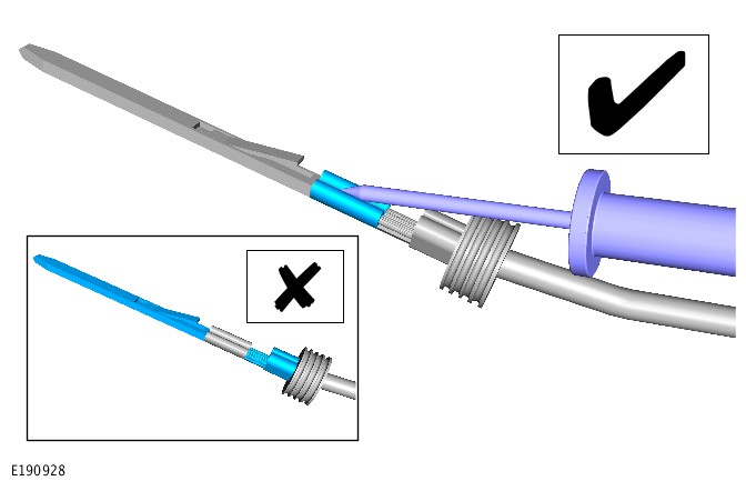
Method 1
E190832

Method 2
E190928

The following 2 methods of electrical connector probing are not allowed.

Method 1. Probing at the rear of sealed electrical connectors (see illustration E190926).

Method 2. Probing at the electrical connector contact area (see illustration E190927).
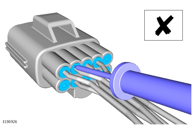
Method 1
E190926

Method 2
E190927

3.12 Live Probing on Sealed Connectors

WARNINGS:

  • This procedure must never be done on any of the following. Failure to follow this instruction may result in personal injury;
    • SRS
    • Pedestrian protection system
    • Throttle Control circuits
    • Speed Control circuits
    • Link lead assembles, which are unique to safety critical circuits such as ABS and thermocouple circuits. An example of this is the ABS wheel speed sensors with molded connectors
  • This procedure must only be done on wire with a cross sectional area of 0.5 mm squared or less.

CAUTIONS:

  • The link lead used in this procedure must have a cross sectional area of at least 0.5 mm squared.
  • The battery ground cable must be disconnected before any electrical connectors are disconnected / reconnected.
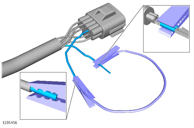
E195456

  1. Disconnect the battery ground cable.
  2. CAUTION:

    Before extracting any terminals, refer to the Electrical Connector Terminal Extraction and Extraction Tools sections of this document for more information.

    Extract the terminal to be tested from the electrical connector
  3. Insert a substitute wire with the same terminal and cross sectional area of the previously extracted wire, into the vacated position of the electrical connector.
  4. CAUTION:

    The link lead clip must only be attached to the portion of the extracted terminal that is crimped directly to the section of non-insulated wire.

    Attach 1 end of the link lead to the original wire terminal.
  5. CAUTION:

    The link lead clip must only be attached to the non-insulated section of the wire.

    Attach the remaining end of the link lead to the substitute wire.
  6. Reconnect the electrical connector.
  7. Reconnect the battery ground cable and begin the test.

3.2 Pin Drag Test

This is not allowed.

3.3 Grommets

Grommets - repair/replacement and additional circuits

Solid (over moulded) grommets are non-repairable and must be replaced by the installation of a new harness. Grommets with plastic inserts for panel retention – the inserts can be removed and replaced where necessary.

EPDM (Rubber) grommets: if the grommet is damaged then a 1 off attempt to repair with a suitable automotive grade silicon sealant is allowed. When the repair is completed, test for leaks (noise/fumes/water). If this fails to seal then the harness must be replaced.

If any vehicle accessories are added that require additional wires/circuits to pass through a sealed grommet then these must be routed through the service nipple. The service nipple must then be sealed using a suitable automotive grade silicon sealant and installed as shown below.

Rubber Grommet With Service Nipple
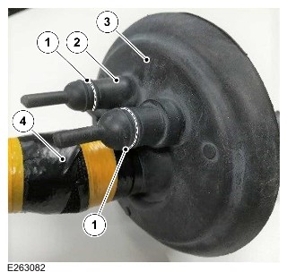
E263082

ItemDescription
1Location to cut
2Secure with cable tie
3Grommet
4Existing harness

3.4 Harness/cable clips

Clip/Fixing repair/replacement

The following applies to 12V applications

When doing any Electrical Distribution System (EDS) repairs or investigating vehicle faults/failures the following guidelines must be followed:

  • Broken clips and fixings must be replaced
  • Damaged/worn clips and fixings that could fail in service must be replaced
  • When a harness is removed to facilitate vehicle/powertrain strip down it may compromise the retention performance of some clips/fixing types. Any clip/fixing that is used in an area subject to dynamic movement or high vibration whose retention features were damaged by removal during strip down must be replaced.

The majority of clips/fixings are listed in the following table.

Push old or damaged fixing out of the way (turning it around the harness if necessary) and put on new fixing. Inspect fixing positioning to make sure that the harness is not close to anything hot, sharp or dynamic.

JLR Part NumberManufacturerManufacturer Part NumberComments
KHC2-13A506-DAHellerman-Tyton157-00228Tie Wrap
KHC2-13A506-AAHellerman-Tyton142-294Tie Wrap
JHC2-13A506-MAA Raymond206756000Tie Wrap
KHC2-13A506-FAITW31214814Tie Wrap
JHC2-14A282-AAHellerman-Tyton157-00014Tie Wrap
KHC2-13A506-EAA Raymond225997Tie Wrap
JHC2-13A506-SAA Raymond230347Tie Wrap
KHC2-14197-AAA Raymond215148Tape on
JHC2-14197-RAA Raymond209423Tape on
JHC2-14197-YAITW1750006750Tape on
JHC2-14197-JAHellerman-Tyton155-11601Tape on
KHC2-14197-DAA Raymond201340Tape on
JHC2-14197-HAA Raymond201336Tape on
KHC2-14197-FAHellerman-Tyton151-00650Tape on
JHC2-14197-ABBA Raymond201878Tape on
JHC2-14197-ABCA Raymond019998000Tape on
KHC2-14197-CAA Raymond248112-2Tape on
KHC2-14197-EAA Raymond215150Tape on
KHC2-14197-GAHellerman-Tyton151-01117Tape on
JHC2-13A506-ABAA Raymond208738Tie Wrap
JHC2-14197-ABGA Raymond224250Used with JHC2-13A506-ABA
KHC2-13A506-BAHellerman-Tyton150-40591Tie Wrap
KHC2-14A169-AAITW09760.00Stud Fixing
KHC2-14A169-BAA Raymond214658Stud Fixing
JHC2-13A506-T AA Raymond202587Stud Fixing/Tie Wrap
JHC2-14197-ABHA Raymond201337Tape on
KHC2-14A169-DAA Raymond253723Stud Fixing
KHC2-14197-BAA Raymond233291Tape on
KHC2-14A282-AAHellerman-Tyton155-30702Anti Rotation
KHC2-14A282-BAITW30413438Anti Rotation
JHC2-14A163-N AA Raymond235920C Clip
JHC2-14A163-LAA Raymond235922C Clip
JHC2-14A163-MAA Raymond235923C Clip
KHC2-13A506-GAITW31811311ATie Wrap
JHC2-13A506-VAHellerman-Tyton156-01425Tie Wrap
JHCT-14A163-HAA Raymond249154C Clip
KHC2-13A506-CAHellerman-Tyton156-00329Tie Wrap

The following applies to 48V MHEV and HV applications.

All HV fixings are classified as ‘critical’ for the vehicle assembly process. Threaded fixings must be reassembled using the specified torque (published in the Work Shop Manual/TOPIx). For all HV fixings, wherever possible the damaged part is to be displaced/pushed out of the way. The damaged part must be left in place and the new part installed alongside in the exact location of the old/previous fixing. Where the fixing must be removed to facilitate replacement then extreme care must be used to prevent risk of damage to the cables and coverings

4. WIRING HARNESS REPAIR

4.1 APPROVED ELECTRICAL WIRING HARNESS REPAIR METHODS

CAUTION:

Several different types and sizes of terminal may be found in a single electrical connector housing.

It is necessary to identify:

  • The conductor (wire) size of the affected wiring harness
  • The electrical connector range from which the damaged wiring harness is to be removed
  • The electrical terminal type

Use of the JLR approved diagnostic equipment will greatly assist in the quick identification of electrical connectors and damaged pin terminal(s).

Reference can also be made to the ERL and Interactive Electrical Wiring Diagram (iEWD) available through TOPIx, to identify wiring harness(s) and electrical connector(s).

Use the Electrical Wiring Harness Repair Relationship Table to identify the correct splice connector to suit the wiring harness conductor (wire) size. This will relate to a suitable pre-terminated lead by the color of the insulation. The table also identifies the correct length of insulation to be stripped from the wiring harness lead.

Electrical Wiring Harness Repair Relationship Table

CABLE SIZE RANGESPLICE CONNECTORSTRIP LENGTH
0.35 to 1.50 mm² (0.00054 to 0.0023 inch²)RED6.00 to 7.00 mm (0.23 to 0.27 inch)
1.00 to 2.50 mm² (0.0016 to 0.0039 inch²)BLUE6.00 to 7.00 mm (0.23 to 0.27 inch)
4.00 to 6.00 mm² (0.0062 to 0.0093 inch²)YELLOW9.00 to 9.50 mm (0.35 to 0.37 inch)

Electrical Connector Terminal Extraction

It must be noted that some electrical connector(s) have anti-backout devices which prevent the terminals from being removed from the electrical connector. Some examples of these are shown in following illustrations. The anti-backout device must be released before attempting to remove the terminal from the electrical connector. Some anti-backout devices require a special tip to release the device. Refer to the ERL for the correct tool(s) to use (where applicable).

Various types of electrical connector have seals installed internally or externally to prevent moisture ingress. These normally do not have to be removed but make sure that they are installed when the electrical connectors are connected.

CAUTION:

Inspect the electrical connector housing for evidence of damage. The damage may affect the security of a terminal inside the connector housing. The damage may affect the operation of the anti-backout device. The damage may affect the secure installation of the connector housing to the intended component/connector housing. Replace a damaged electrical connector housing.

The illustrations show examples of some of the common styles of extraction tools used on different types of electrical connector(s). Care must be exercised to avoid further damage when removing the terminals from the electrical connector.

NOTE:

Examples of the extraction tools and anti-backout devices.
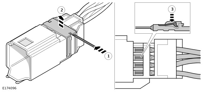
A
E174096

B
E174097

C
E174098

D - 1
E174099

D - 2
E174100

E
E174101

F
E174102

G
E174103

H
E174104

I
E174105

J
E174106

K
E174655

L
E174656

M
E174657

N
E174658

4.2 Types of Electrical Wiring Harness Splice Repairs

Splice connectors are available in 3 sizes; refer to Pre-Terminated Lead and Splice Connectors in the Electrical Wiring Harness Repair Components section.

A splice connector can be used in a number of ways to achieve an effective and robust wiring harness repair.

NOTE:

For all repairs the wire being repaired must not be under any Extension forces when the circuit is connected to the intended component or connector housing etc. If the wire is too short when the damage has been removed, it must be returned to the appropriate length. This requires inserting an extension wire into the center of the splice repair; refer to Double Splice Extension Repair.

The following information will show and explain the variations of splice joints achievable; these are:

  • A 1 Wire Splice Repair
  • A 2 Wire Splice Repair
  • Pulled Out Wire Splice Repair
  • Damaged Splice Repair
  • Double Splice Extension Repair
  • Splice Repair to Wire Smaller than 0.35 mm² (0.00054 inch²)

A 1 Wire Splice Repair

If a wire has damage isolated to the wire only without any further damage to the terminal or connecter, the damaged portion of wire can be removed. Remove the damaged part of the wire by cutting each side of the damaged area and reconnected using the appropriate splice connector.

A 1 Wire Splice Repair Example
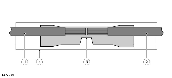
E177956

  1. Original Wire
  2. Original Wire
  3. Splice Connector
  4. Glue Lined Heat Shrink Sleeve

A 2 Wire Splice Repair

To repair wiring harnesses with damaged eyelets, use a splice connector with a suitable pre-terminated lead with the appropriate eyelet and wire size. See table below for more information.

Eyelet Hole SizeInterlocking PairWire Size
Less than 5 mm (0.2 inch) diameterNot Applicable418781
Greater than 5 mm (0.2 inch) diameterYesSmall 418778
Greater than 5 mm (0.2 inch) diameterYesMedium 418779
Greater than 5 mm (0.2 inch) diameterYesLarge 418780
Greater than 5 mm (0.2 inch) diameterNoLarge Pair 418783 and 418785
Greater than 5 mm (0.2 inch) diameterNoSmall Pair 418782 and 418784

NOTES:

  • If the damaged eyelet is from an interlocking pair, it is recommended to replace both eyelets.
  • If any harness(s) with large multi wire ground eyelets give cause for concern, new components must be installed.

If the wiring harness has a damaged eyelet with 2 wires to the eyelet, it is recommended to use a suitable pre-terminated lead. The lead must have a cross sectional area equal to or greater than that of the 2 wires combined to complete the repair.

A 2 Wire Splice Repair Example
E177957

  1. Pre-terminated Lead
  2. Original Wire
  3. Original Wire
  4. Splice Connector
  5. Glue Lined Heat Shrink Sleeve

Pulled Out Wire Splice Repair

If a wire has become disconnected from its splice, it can be repaired by splicing the disconnected wire to 1 of the wires still part of the original splice.

Cut the undamaged wire of the original splice and with a suitable splice connector, clamp the splice side of the wire. Install a suitable section of glue lined heat shrink sleeve to the splice the wire had disconnected from. Insert the disconnected wire and the undamaged wire into the splice connector and clamp the splice connector.

Pulled Out Wire Splice Repair Example
E177958

  1. Original Splice
  2. Glue Lined Heat Shrink Sleeve
  3. Original Undamaged Wire
  4. Pulled Out Wire
  5. Original Undamaged Wire
  6. Splice Connector
  7. Glue Lined Heat Shrink Sleeve

Damaged Splice Repair

If a wiring harness has splice which has been damaged, the splice must be removed and replaced.

Remove the damaged splice by cutting it from the wiring harness, making sure to leave as much undamaged wire as possible on the wiring harness. Using 1 or more suitable splice connectors make a new splice.
Damaged Splice Repair Example
E177959

  1. Original Wire
  2. Original Wire
  3. Original Wire
  4. Original Wire
  5. Splice Connector
  6. Glue Lined Heat Shrink Sleeve

Double Splice Extension Repair

If the wire(s) being repaired are too short when the damage area of wire has been removed the following is recommended. Use 2 splice connectors and an appropriate length of wire with colored cable identification sleeves to return the wire its original length.

The extension wire must have the same or greater cross sectional area as the wire(s) combinations entering the splice connectors. Example: 2 wires x 0.5 mm² (0.00077 inch²) cross sectional area + 2 wires x 0.75 mm² (0.0012 inch²) cross sectional area would require a wire of 2.5 mm² (0.0039 inch²) cross sectional area or greater.

Double Splice Extension Repair Example
E177960

  1. Original Wire(s)
  2. Original Wire(s)
  3. Extension Wire
  4. Splice Connector
  5. Glue Lined Heat Shrink Sleeve
  6. Splice Connector
  7. Glue Lined Heat Shrink Sleeve

Splice Repair to Wire Smaller than 0.35 mm² (0.00054 inch²)

To repair a damaged wire with a cross sectional area smaller than 0.35 mm² (0.00054 inch²) do the following. Use the smallest approved splice connector (red) and insert an additional wire with the wire being repaired into each side of the slice connector.

For each splice repair to a wire smaller than 0.35 mm² (0.00054 inch²), an additional piece of wire (0.35 mm² (0.00054 inch²) or 0.5 mm² (0.00078 inch²)) must be used. The additional piece of wire must be inserted into the splice connector with the wire being repaired. to make the joint secure when crimped. When the wires have been crimped into the splice connector, all additional wire(s) must be cut close to the splice connector. This is to make sure the additional wire is fully covered when the glue lined heat shrink sleeve is in position over the splice connector.

Splice Repair to Wire Smaller than 0.35 mm² (0.00054 inch²) Example
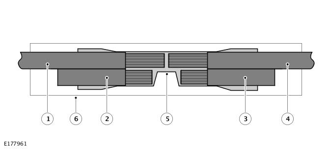
E177961

  1. Original Wire (less than 0.35 mm² (0.00054 inch²))
  2. Additional wire (0.35 mm² (0.00054 inch²) or 0.5 mm² (0.00078 inch²))
  3. Pre-terminated Lead or replacement wire (less than 0.35 mm² (0.00054 inch²))
  4. Additional wire (0.35 mm² (0.00054 inch²) or 0.5 mm² (0.00078 inch²))
  5. Splice Connector
  6. Glue Lined Heat Shrink Sleeve

Repairs to twisted wires

See the individual repair procedure for twisted wire harnesses.

4.3 Wiring Harness Repair Procedure

Before starting any repair of a damaged wire, the damaged wire must be inspected along its length where possible to evaluate the full extent of the damage. If the damage is in a localized area the wire repair is recommended, if the damage is extensive, a replacement harness must be considered. A wire being repaired must be cut at a point where there is no damage to the wire or insulation.

NOTES:

  • If the wire repair requires the use of a pre-terminated lead, the wire must not be cut more than 300 mm (11.8 inch) from a connector housing.
  • A repaired wire must not be under any Extension forces when connected to its intended component/connector housing.

Where there is a requirement to repair more than 1 wire in a harness branch, the splices must be staggered. This will minimize the effect of increasing the diameter of the harness branch. The recommended spacing is 50 mm (2.0 inch) between centers for yellow splices and 40 mm (1.57 inch²) between centers for red or blue splices.

CAUTIONS:

  • Do not use:
    • crimpers
    • insulation (wire) strippers
    • splice connectors
    • heat shrink sleeves
    • pre-terminated leads or wiring harness(s)
  • That are not authorized and supplied through the JLR parts ordering system
  • Where the repair procedure indicates that a glue lined heat shrink sleeve must be applied, apply sufficient heat to the glue lined heat shrink sleeve. This will melt the glue in order to provide a water tight seal. Do not over heat the glue lined heat shrink sleeve so that the wiring harness insulation becomes damaged.

There is no specific limit on the number of splices that can be used in a harness branch. The responsible technician must judge the number of splices that can be installed along the available length of harness and within the space in which the harness is located.

Consideration must be given to any requirement to bend the harness and the risks of the repaired harness rubbing, squeaking or rattling against adjacent parts, body panels or trim.

Wiring Harness Repair Process

  1. Remove the damaged terminal from the electrical connector using the correct extraction tool. Make sure that any anti-backout device is released before trying to remove the terminal.
  2. CAUTION:

    A number of electrical connector terminals are gold plated or gold flashed. When damaged, they must be installed with a gold pre-terminated wiring harness(s). It is not always easy to identify the female as gold but the male pins are visually easier. Therefore always inspect both male and female terminals to identify those which are gold. Under no circumstances are gold and tin terminals to be mixed as this will lead to early failure of the electrical contact.

    NOTE:

    Never use a harness lead with a smaller diameter than the original harness lead.

    Select the correct size and type of pre-terminated wiring lead and splice connector; refer to Wire Chart and Service Repair Information.
  3. Using the wire cutter on the insulation (wire) stripper, cut the pre-terminated wiring harness and the harness cable to the required length.
  4. NOTE:

    See illustration: Stripping Insulation

    From the Electrical Wiring Harness Repair Relationship Table, find the correct length of insulation to be stripped from the pre-terminated lead. Set the adjustable cable length stop to the correct length. Place the pre-terminated lead in the insulation (wire) stripper and remove the insulation.
  5. Put the cable identification sleeve(s) on to the wiring harness with the main cable color nearest to the terminal.
  6. During this next step take care only to close the crimpers far enough to hold the splice connector firmly in position. Place the selected splice connector in the crimpers, matching the aperture and the splice connector colors. Make sure that the window indentation in the splice connector is resting over the guide bar on the lower jaw. Partially close the grip until the splice connector is securely held in the aperture. This will give support to the splice connector while the wiring harness(s) are inserted into it.
  7. NOTE:

    See illustration: Splice Correctly Located

    Insert the pre-terminated lead into the splice connector and make sure that the wire is against the wire stop. Close the grip firmly, crimping the pre-terminated lead to the splice connector. When the handles have been completely closed the splice connector will be freed from the tool as the handles are released. If the handles have not been completely closed then the jaws will hold the splice connector and it cannot be removed from the tool.
  8. Make sure that the wiring harness cable has been squarely cut and the correct length of insulation removed. If more than 1 splice is needed the splice connectors must be not be crimped to the wiring harness at the same distance from the connector. The splices must be staggered to prevent a bulk of splices in the same area of the wiring harness.
  9. It is preferable to cover the splice joint with a glue lined heat shrink sleeve. This is desirable not essential, except where the electrical connector is a sealed electrical connector. Use the smaller diameter glue lined heat shrink sleeve for red and blue pre-terminated lead(s). Use the large diameter glue lined heat shrink sleeve for the yellow pre-terminated lead(s). It is advisable to place the heat shrink sleeve over the completed joint but in some instances the glue lined heat shrink sleeve will not pass over the terminal. Inspect, and if required, place the correct size glue lined heat shrink sleeve onto the harness cable or pre-terminated lead before crimping the splice to the wiring harness.
  10. Place the harness cable into the splice with the splice window over the guide bar. Make sure that the harness cable is against the stop in the splice, crimp the splice connector to the wiring harness.
  11. Gently pull the harness cables each side of the splice connector to make sure that a secure joint has been made.
  12. WARNING:

    Do not use a naked flame in areas where fuel or oil have been spilt. Clean the area of residual oil and fuel and wait until the fuel spill has fully evaporated.

    CAUTIONS:
    • When using a heat source make sure that it is localized and causes no damage to surrounding materials.
    • Where the repair procedure indicates that a glue lined heat shrink sleeve must be applied, apply sufficient heat to the glue lined heat shrink sleeve. This will melt the glue in order to provide a water tight seal. Do not over heat the glue lined heat shrink sleeve so that the wiring harness insulation becomes damaged.
    Using a suitable heat source, shrink the sleeve over the splice.
  13. If further pre-terminated lead(s) are to be installed to the same electrical connector, make sure that the lead is cut at a different length to the previous joint. This makes sure that the splices will, where possible, be staggered on the wiring harness and prevent a bulk of splices in 1 area.
  14. When all of the splices have been made, install the terminal(s) to the electrical connector, taking care that the terminals are correctly oriented.
  15. Install the wiring harness cover and secure with adhesive electrical tape. Do not cover the wiring harness right to the electrical connector. The terminals must have a little movement and not be firmly bound to the electrical connector or wiring harness. Make sure that the cable identification sleeve(s) are showing at the wiring harness electrical connector.
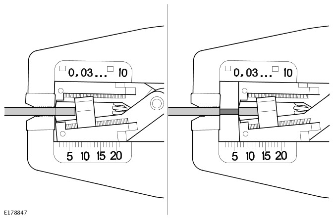
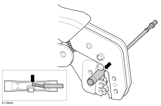
Stripping Insulation
E178847

Splice Correctly Located
E178868

4.4 Electrical Wiring Harness Repair Components

The electrical wiring harness repair components comprises of:

  • Pre-terminated leads of different sizes and types
  • Splice connectors in 3 sizes
  • A selection of colored cable identification sleeves
  • Glue lined heat shrink sleeves in 2 sizes.

NOTE:

A suitable heat source, for shrinking the glue lined heat shrink sleeves will be required.

The pre-insulated diamond grip range of electrical connector terminals and in-line splice connectors are the only acceptable product for the repairs of wiring harnesses. The splice connectors not only grip the wire but also the insulation, making a very secure joint.

Pre-Terminated Lead and Splice Connectors

The pre-terminated lead(s) are supplied with the insulation in 1 of 3 colors, red, blue or yellow. The colors indicate the cable size range and not any particular circuit; refer to the Electrical Wiring Harness Repair Relationship Table in the Section 4.1.

Splice connectors are also supplied with red, blue or yellow coverings, which must be matched to the pre-terminated lead insulation color.

For ease and speed, some of the pre-terminated lead(s) may already have the insulation partly stripped at the splice end. If the repair requires insulation to be stripped from the cable, refer to the Electrical Wiring Harness Repair Relationship Table in the Repair Methods section. The correct length of insulation to be stripped will be detailed in the table.

Wire Chart and Service Repair Information

This information is part of the relevant ERL or iEWD available through TOPIx.

NOTE:

Access to information about the pre-terminated leads for vehicles supported by the iEWD is achieved by hovering the screen pointer over the relevant connector number and left-clicking.

When the relevant connector housing has been identified, refer to the associated Wire Chart and Service Repair Information. This is to make sure the installation of pre-terminated leads or wiring harnesses are completed in the approved manner.

  • Identify the connector cavity in which the terminal needs replacing
  • Make a note of the cross sectional area of the associated wire
  • Make a note of the part number of the appropriate pre-terminated lead
  • Make a note of the correct terminal extraction tool (where applicable)

Before commencing a wiring harness repair, always make sure the correct pre-terminated leads and associated repair parts have been ordered using the JLR parts ordering system.

Some of the pre-terminated leads have seals installed to the insulation for sealed connector applications. Where, as part of a repair, sealed terminals are removed, it is essential that those terminals are replaced by sealed pre-terminated leads.

Wire chart and service repair information also includes:

  • The destination of the cable
  • The applicable tools and associated other parts necessary to make sure the pre-terminated lead is correctly installed in the approved manner

CAUTIONS:

  • Where the repair procedure indicates that a glue lined heat shrink sleeve must be applied, apply sufficient heat to the glue lined heat shrink sleeve. This will melt the glue and provide a water tight seal. Do not over heat the glue lined heat shrink sleeve so that the wiring harness insulation becomes damaged.
  • Do not use any heat shrink sleeve other than the approved glue lined heat shrink sleeve specified in the repair procedure.

Glue Lined Heat Shrink Sleeving

There are 2 sizes of glue lined heat shrink sleeving available. Each heat shrink sleeve contains a sealant glue. These must be used when connecting wiring harness(s) or electrical connector terminal(s) at all times. The smaller diameter glue lined heat shrink sleeve is to be used with the red and blue splice connectors. The larger diameter glue lined heat shrink sleeve is to be used with the yellow splice connectors.

Wiring Harness Cable Identification Sleeves

A selection of colored sleeves are available for maintaining the wiring harness cable identification on the pre-terminated lead.

The sleeve identification packs are available to suit the 3 cable size ranges of Red, Blue and Yellow. Each sleeve identification pack contains 50 of each of the following colored sleeves:

  • Black
  • Brown
  • Red
  • Orange
  • Yellow
  • Green
  • Blue
  • Violet
  • Gray
  • White

Place the correct colored sleeve(s) over the pre-terminated lead insulation as near to the electrical connector as possible. The main wiring harness cable color must be nearest to the electrical connector.

For example: if the original wiring harness cable color is green with a black trace:

  1. Put the green wiring harness cable identification sleeve on the pre-terminated lead first
  1. Put the black wiring harness cable identification sleeve on the pre-terminated lead second
  1. Slide both sleeves along the wiring harness cable to the electrical connector terminal.

Wiring Harness Repair Parts

NOTE:

Repair components can be ordered through the JLR parts ordering system.

DescriptionPart NumberQuantity
Glue Lined Heat Shrink Sleeve Pack – small diameter418-10425 per pack
Glue Lined Heat Shrink Sleeve Pack – larger diameter418-10510 per pack
Case Assembly Comprising – carry case, lid, inner lid, base, insert, trays foam spacers418-1061
Splice Connector – Red418-10750 per pack
Splice Connector – Blue418-10850 per pack
Splice Connector – Yellow418-10920 per pack
Sleeve Identification Pack – for Red insulation418-112500
Sleeve Identification Pack – for Blue insulation418-113500
Sleeve Identification Pack – for Yellow insulation418-114500

4.5 Wiring Harnesses

CAUTION:

Disconnect the battery before commencing the repair of any wiring harness.

The repair is only appropriate where the damage is localized and is not over the full length of the wiring harness. If the damage is end to end then replacing the whole harness must be considered where appropriate. The damaged section of wiring harness must be removed by cutting either side of the damage at a point where the wiring harness retains its original condition. The number of twists in a twisted pair of wires is important to the functionality of the circuit and as such must be maintained. Note the number of twist over the repair length prior to commencing the repair. The same number of twists must reintroduced after completing the repair.

If repairing multiple wires within a harness, stagger the connecting splices and twist the wire between the connecting splice locations. This will minimize the untwisted length and the effect of increasing the diameter of the harness. On no account must the untwisted length exceed 50 mm (2.0 inch) each side of the connecting splice. When each connecting splice repair is completed, cover the splice with a black glue lined heat shrink sleeve. Use an approved hot air applicator to shrink the sleeve until the glue is visible at both ends. Make sure that connecting splice repairs are not located in any dynamic movement area of a harness.

When all wiring harness repairs are complete, the wiring harness must be wrapped in insulating tape and returned as close as possible to new vehicle condition. Make sure the wiring harness follows the original routing and all clips and connectors are installed.

CAUTION:

Under no circumstances must repair be attempted to the following:

  • Link lead assembles, which are unique to safety critical circuits such as ABS and thermocouple circuits. An example of this is the ABS wheel speed sensors with moulded connectors.
  • Screened cables, leads and wiring harness(s).

If any harness(s) with damaged electrical connector terminals or cables from the above circuits give cause for concern, new components must be installed.

CAUTIONS:

  • Do not attempt to repair or reform a damaged electrical connector terminal. A damaged electrical connector terminal must be replaced using the correct pre-terminated lead.
  • A ground point connector with multiple wires to the connector must not be repaired as a complete connector. If a damaged wire is identified, the wire can be repaired individually using the correct pre-terminated lead.
  • Do not attempt the repair of damaged battery, hybrid and power cables.

    These types of cable generally have a cross sectional area larger than 6 mm² (0.009 inch²) and must only be replaced. If the original cable is contained within the harness bundle the original cable must be left in the harness. Attach the replacement cable to the harness along the original harness route.

    The replacement cable must follow the original cable route to avoid the risk of introducing electrical interference issues. The original cable connections must be cut from the cable at both ends and discarded. The exposed cable ends must be free from sharp edges and strands of wire. The exposed cable must be over taped to prevent injury before being taped back to the main harness.

If any harness(s) with damaged electrical connector terminals or cables from the above circuits give cause for concern, new components must be installed.

4.5.1 Electrical Wiring Harness Repair Components

The electrical wiring harness repair components comprises of:

  • Pre-terminated leads of different sizes and types
  • Splice connectors in 3 sizes
  • A selection of colored cable identification sleeves
  • Glue lined heat shrink sleeves in 2 sizes.

NOTE:

A suitable heat source, for shrinking the glue lined heat shrink sleeves will be required.

The pre-insulated diamond grip range of electrical connector terminals and in-line splice connectors are the only acceptable product for the repairs of wiring harnesses. The splice connectors not only grip the wire but also the insulation, making a very secure joint.

Pre-Terminated Lead and Splice Connectors

The pre-terminated lead(s) are supplied with the insulation in 1 of 3 colors, red, blue or yellow. The colors indicate the cable size range and not any particular circuit; refer to the Electrical Wiring Harness Repair Relationship Table in the Repair Methods section.

Splice connectors are also supplied with red, blue or yellow coverings, which must be matched to the pre-terminated lead insulation color.

For ease and speed, some of the pre-terminated lead(s) may already have the insulation partly stripped at the splice end. If the repair requires insulation to be stripped from the cable, refer to the Electrical Wiring Harness Repair Relationship Table in the Repair Methods section. The correct length of insulation to be stripped will be detailed in the table.

Wire Chart and Service Repair Information

This information is part of the relevant ERL or iEWD available through TOPIx.

NOTE:

Access to information about the pre-terminated leads for vehicles supported by the iEWD is achieved by hovering the screen pointer over the relevant connector number and left-clicking.

When the relevant connector housing has been identified, refer to the associated Wire Chart and Service Repair Information. This is to make sure the installation of pre-terminated leads or wiring harnesses are completed in the approved manner.

  • Identify the connector cavity in which the terminal needs replacing
  • Make a note of the cross sectional area of the associated wire
  • Make a note of the part number of the appropriate pre-terminated lead
  • Make a note of the correct terminal extraction tool (where applicable)

Before commencing a wiring harness repair, always make sure the correct pre-terminated leads and associated repair parts have been ordered using the JLR parts ordering system.

Some of the pre-terminated leads have seals installed to the insulation for sealed connector applications. Where, as part of a repair, sealed terminals are removed, it is essential that those terminals are replaced by sealed pre-terminated leads.

Wire chart and service repair information also includes:

  • The destination of the cable
  • The applicable tools and associated other parts necessary to make sure the pre-terminated lead is correctly installed in the approved manner

CAUTIONS:

  • Where the repair procedure indicates that a glue lined heat shrink sleeve must be applied, apply sufficient heat to the glue lined heat shrink sleeve. This will melt the glue and provide a water tight seal. Do not over heat the glue lined heat shrink sleeve so that the wiring harness insulation becomes damaged.
  • Do not use any heat shrink sleeve other than the approved glue lined heat shrink sleeve specified in the repair procedure.

Glue Lined Heat Shrink Sleeving

There are 2 sizes of glue lined heat shrink sleeving available. Each heat shrink sleeve contains a sealant glue. These must be used when connecting wiring harness(s) or electrical connector terminal(s) at all times. The smaller diameter glue lined heat shrink sleeve is to be used with the red and blue splice connectors. The larger diameter glue lined heat shrink sleeve is to be used with the yellow splice connectors.

Wiring Harness Cable Identification Sleeves

A selection of colored sleeves are available for maintaining the wiring harness cable identification on the pre-terminated lead.

The sleeve identification packs are available to suit the 3 cable size ranges of Red, Blue and Yellow. Each sleeve identification pack contains 50 of each of the following colored sleeves:

  • Black
  • Brown
  • Red
  • Orange
  • Yellow
  • Green
  • Blue
  • Violet
  • Gray
  • White

Place the correct colored sleeve(s) over the pre-terminated lead insulation as near to the electrical connector as possible. The main wiring harness cable color must be nearest to the electrical connector.

For example: if the original wiring harness cable color is green with a black trace:

  1. Put the green wiring harness cable identification sleeve on the pre-terminated lead first
  1. Put the black wiring harness cable identification sleeve on the pre-terminated lead second
  1. Slide both sleeves along the wiring harness cable to the electrical connector terminal.

Wiring Harness Repair Parts

NOTE:

Repair components can be ordered through the JLR parts ordering system.

DescriptionPart NumberQuantity
Glue Lined Heat Shrink Sleeve Pack – small diameter418-10425 per pack
Glue Lined Heat Shrink Sleeve Pack – larger diameter418-10510 per pack
Case Assembly Comprising – carry case, lid, inner lid, base, insert, trays foam spacers418-1061
Splice Connector – Red418-10750 per pack
Splice Connector – Blue418-10850 per pack
Splice Connector – Yellow418-10920 per pack
Sleeve Identification Pack – for Red insulation418-112500
Sleeve Identification Pack – for Blue insulation418-113500
Sleeve Identification Pack – for Yellow insulation418-114500

4.5.2 Wiring Harness Repair Tools

NOTE:

Replacement repair equipment can be ordered from the equipment workshop website; refer to the Replacement Repair Equipment in the Introduction section.

The wiring harness repair tools comprises of:

  • A selection of extraction tools
  • A wire cutter and insulation stripper
  • Crimpers

Extraction Tools

The extraction tools are used to remove a terminal from an electrical connector. Refer to the Wire Chart and Service Repair Information for the correct extraction tool for each terminal (where applicable). Each extraction tool has been specially designed to extract a particular type of electrical connector terminal. The use of any other tool is not recommended and is liable to cause damage to the electrical connector.

CAUTION:

Inspect the electrical connector housing for evidence of damage. The damage may affect the security of a terminal inside the connector housing. The damage may affect the operation of the anti-backout device. The damage may affect the secure installation of the connector housing to the intended component/connector housing. Replace a damaged electrical connector housing.

Insulation (Wire) Stripper

By pressing the outer edges of the wiring harness cable length stop together the adjuster can be slid up or down the jaw. This decreases or increases the length by which the cable insulation will be stripped from the pre-terminated lead or wiring harness cable.

NOTE:

Some wiring harness insulation may be harder and require more effort to make a clean strip but exercise care not to damage the wire.
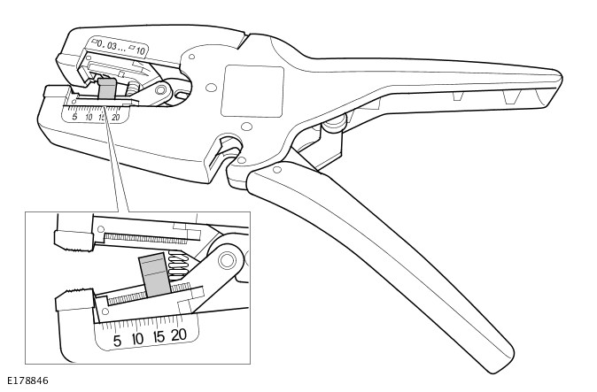
Insulation (Wire) Stripper
E178846

The adjuster has a position indicator to align with a graduated scale and this sets the correct length in millimeters, of insulation to be stripped. The amount of insulation to be stripped is shown in the Electrical Wiring Harness Repair Relationship Table.

The following illustration shows the insulation stripper tool and a wiring harness correctly gripped in the jaws. A wire cutter is provided on the outer side of the fixed jaw.

Cable Correctly Gripped in Stripper Blades
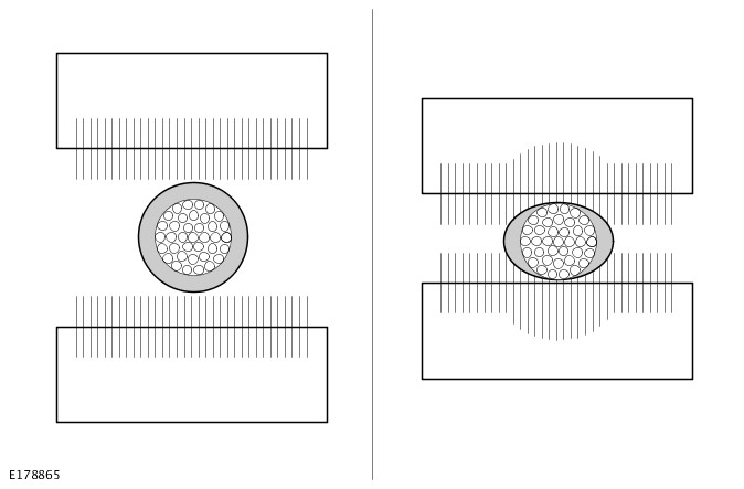
E178865

Crimpers

The crimpers have a moving jaw and a stationary jaw, with 3 different sized crimping enclosures. Each of the enclosures are identified by a red, blue or yellow colored dot which corresponds to the 3 colors of the pre-terminated leads and splice connector.
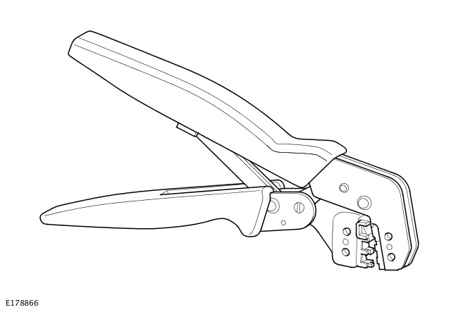
Crimpers
E178866

NOTE:

Replacement repair equipment can be ordered from the equipment workshop website; refer to the Replacement Repair Equipment in the Introduction section.

DescriptionPart NumberQuantity
Crimpers418-116A1
Wire Stripper418-6721


Instrument Panel Wiring Harness (G2417595)

REMOVAL AND INSTALLATION

  • 86.70.10
  • Instrument Panel Wiring Harness - Renew
  • All Derivatives
  • 8.10
  • USED WITHINS

Removal

NOTES:

  • This procedure contains some variation in the illustrations depending on the vehicle specification, but the essential information is always correct.
  • This procedure contains illustrations showing certain components removed to provide extra clarity.
  1. Disconnect the startup battery ground cable.Refer to: 12V System Disconnect and Connect (414-00 Battery and Charging System - General Information, General Procedures).
  2. Remove the instrument panel cross-car beam.Refer to: Instrument Panel Cross-Car Beam (501-12 Instrument Panel and Console, Removal and Installation).
  3. E254746
    • Disconnect the 3 electrical connectors.
    • Release the 2 wiring harness clips.
  4. E254844 Release the 2 wiring harness clips.
  5. E254749
    • Remove the 2 ground bolts.
    • Release the 13 wiring harness clips.
  6. E254839
    • Remove the ground bolt.
    • Disconnect the 4 electrical connectors.
    • Release the 7 wiring harness clips.
  7. E254840
    • Remove the 3 bolts.
    • Release the 4 wiring harness clips.
  8. E254841 Remove the instrument panel wiring harness.
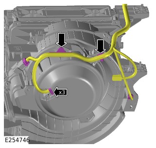
Installation

  1. NOTE:

    Make sure that all the clips are correctly installed.

    • Install the instrument panel wiring harness.
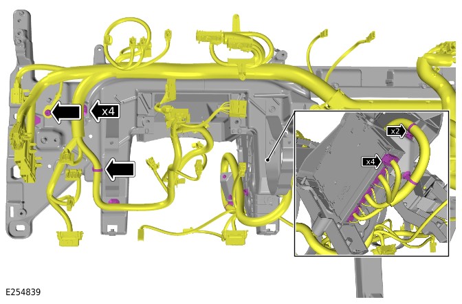
    • Install and tighten the 3 bolts.Torque: 9Nm
    • Install and tighten the 3 ground bolts.Torque: 12Nm
    • Connect the 7 electrical connectors.
    • Install the 28 wiring harness clips.


COMPONENT LOCATION

Component Location - 1 Of 5

NOTES:

  • right hand drive (RHD) vehicle is shown, left hand drive (LHD) vehicle is similar.
  • Vehicle with 5 doors is shown. Vehicle with 3 doors is similar.
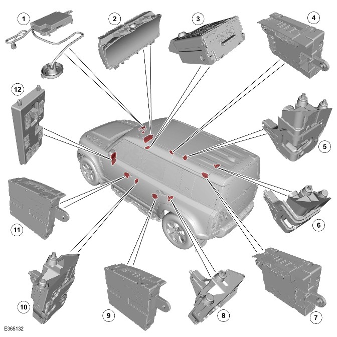
E365132

ItemDescription
1Volumetric sensor
2
3>span class="acronym">Immobilizer Antenna Unit (IAU)
4Driver Front Door Module (DDM)
5Ajar switch - Driver door
6Ajar switch - Rear right door
7Driver Rear Door Module (DRDM)
8Ajar switch - Rear left door
9Passenger Rear Door Module (PRDM)
10Ajar switch - Passenger door
11Passenger Front Door Module (PDM)
12Body Control Module (BCM)/Gateway Module A (GWM)

Component Location - 2 Of 5

E365133

ItemDescription
1Battery Back-Up Sounder (BBUS) - If equipped
2Left hood latch
3Horn - Left
4Hood safety latch
5Right hood latch
6Horn - Right
7Passive sounder - If equipped

Component Location - 3 Of 5

NOTES:

  • RHD vehicle is shown, LHD vehicle is similar.
  • Vehicle with 5 doors is shown. Vehicle with 3 doors is similar.
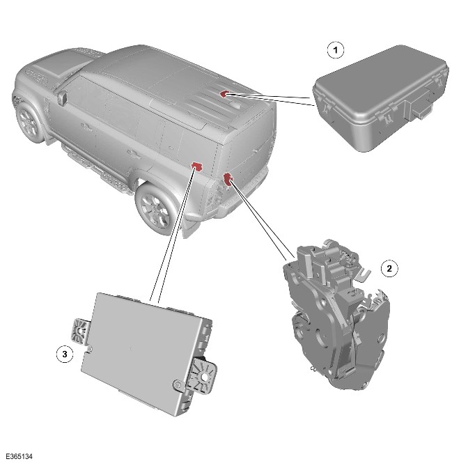
E365134

ItemDescription
1Radio Frequency (RF) receiver
2Tailgate ajar latch
3Remote Function Actuator (RFA)

Component Location - 4 Of 5

NOTES:

  • RHD vehicle is shown, LHD vehicle is similar.
  • Vehicle with 5 doors is shown. Vehicle with 3 doors is similar.
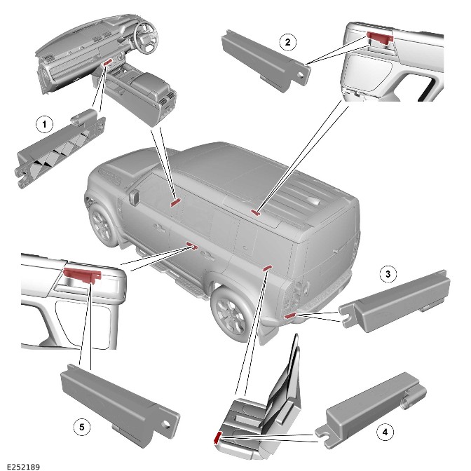
E252189

ItemDescription
1Low Frequency (LF) antenna - Front passenger compartment
2LF antenna - Right passenger compartment
3LF antenna - Left luggage compartment
4LF antenna - Rear passenger compartment - Only for passive start system
5LF antenna - Left passenger compartment

Component Location - 5 Of 5

NOTES:

  • RHD vehicle is shown, LHD vehicle is similar.
  • Vehicle with 5 doors is shown. Vehicle with 3 doors is similar.
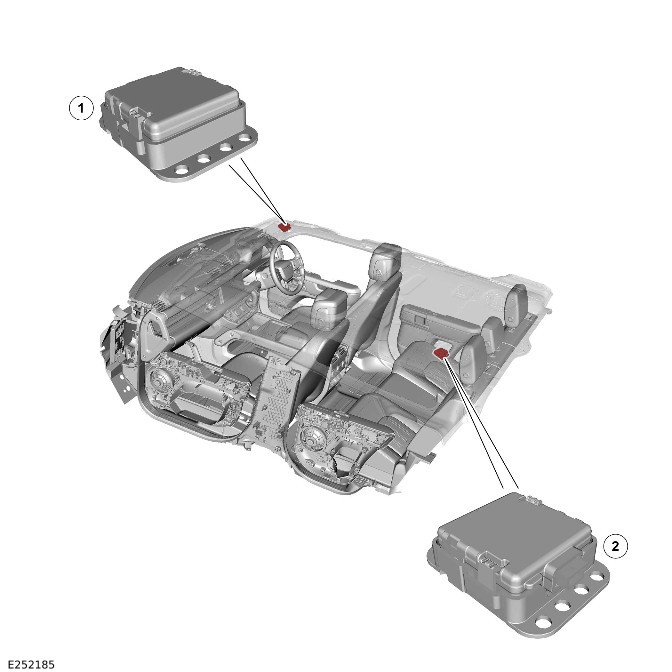
E252185

ItemDescription
1Passive entry transceiver - Front
2Passive entry transceiver - Rear

OVERVIEW

The active anti-theft system monitors all doors, hood and tailgate for unauthorized opening. In some markets the anti-theft system also incorporates monitoring of the passenger compartment and tilt sensing.

The active anti-theft system is controlled by the following body system control modules:

  • BCM/GWM
  • DDM
  • PDM
  • PRDM
  • DRDM
  • IPC
  • RFA.

The BCM/GWM is the main controller in the system. The BCM/GWM controls the following security functions, in addition to other vehicle functions:

  • Single locking, double locking (market dependant) and unlocking (both central unlock and single point entry).
  • Monitoring of the hood switch, door ajar switches and the tailgate ajar switch of the Central Door Locking (CDL) system.
  • Passive Entry Passive Start (PEPS)system.
  • Volumetric sensor.
  • Smart key transponder reading.
  • Security sounder - BBUS or passive sounder.
  • Passive arming and disarming.
  • Panic alarm function.
  • Interior lighting.

Depending on vehicle configuration, 2 levels of vehicle anti-theft alarm are available:

  • Perimeter sensing mode - Monitors all opening panels.
  • Perimeter with alarm sensing mode - Monitors the passenger compartment for intrusion and it also incorporates a tilt sensor to monitor when the vehicle is being moved.

NOTE:

Volumetric mode and tilt sensing are not available in certain markets.

Perimeter sensing mode

All apertures (doors, tailgate and hood) are monitored for ajar status (doors ajar and latch status change).

A visual (through turn signal indicators) and audible alarm are emitted through security sounder and vehicle horns (market dependent) in the event of unauthorized access. The alarm is also triggered in the event of an unauthorized start request.

Smart key

The smart key provides the following functions:

  • Unlock (central unlock or single point entry).
  • Single lock and double lock (market dependant).
  • Remote tailgate release.
  • Approach lighting.
  • Panic alarm.

The lock and unlock switches also control a 'lazy' lock and unlock feature. The 'lazy' lock and unlock feature automatically closes or opens the windows with an extended press of the applicable switch. The 'lazy' lock and unlock feature is only available in certain markets and is controlled in conjunction with the door modules.

WARNING:

Never double lock the vehicle with any person or animal inside.

NOTE:

Double locking (DL) is only available in certain markets.

The smart key contains an emergency key. The emergency key can be used in the event of failure of the smart key or the startup battery to unlock the vehicle. The driver door handle contains a mechanical key barrel which can be used with the emergency key to access the vehicle. The emergency key to access the vehicle does not disable the perimeter sensing system. The visual and audible alarm is activated when the door is unlocked/opened. To cancel the alarm, the smart key must be held next to the IAU and the stop/start switch must be operated.

Emergency locking

On the inside face of each door there is an emergency key aperture. The aperture is used with the emergency key in the event of a failure of the startup battery to lock the vehicle.

Remove the cover and insert the emergency key into the aperture to mechanically lock each door in turn. The driver door is always the last door to be locked. The emergency key must be removed from the emergency key aperture before each door is closed.

For additional information, refer to: Handles, Locks, Latches and Entry Systems (501-14 Handles, Locks, Latches and Entry Systems, Description and Operation).

DESCRIPTION

Door Modules

NOTES:

  • RHD vehicle is shown, LHD vehicle is similar.
  • Vehicle with 5 doors is shown. Vehicle with 3 doors is similar.
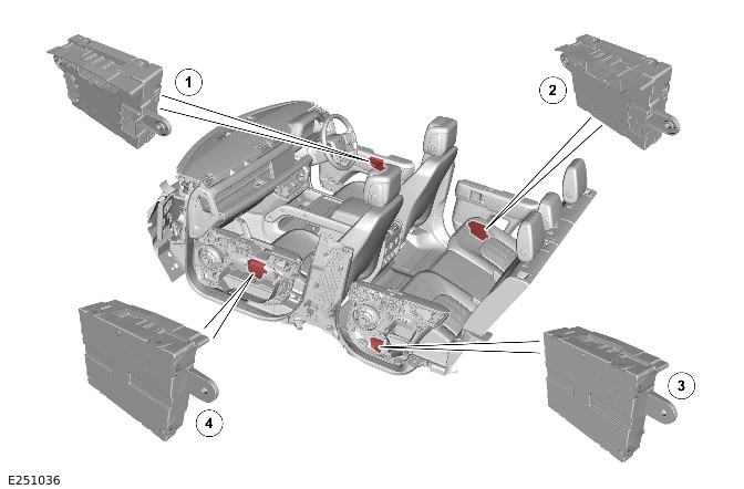
E251036

ItemDescription
1DDM
2DRDM
3PRDM
4PDM

The door modules provide the interface between the door latches and the BCM/GWM. The door modules provide door latches status information and enable the door motors on request from the BCM/GWM.

The DRDM and the PRDM are also controlled by the BCM/GWM. Additionally, the DDM and the PDM also control the door mirror functions.

BCM/GWM

NOTE:

RHD vehicle is shown, LHD vehicle is similar.
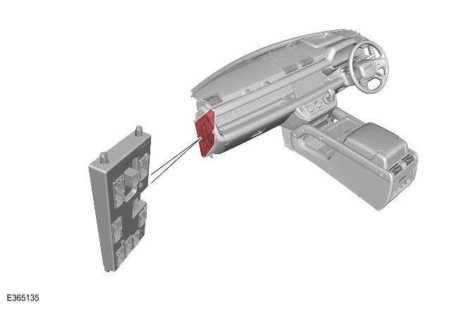
E365135

NOTE:

When the BCM/GWM is replaced, the new module requires configuring to the master car configuration using the Jaguar Land Rover(JLR) approved diagnostic equipment.

The BCM/GWM controls the following components:

  • The horns
  • The tailgate latch
  • The tailgate ajar switch
  • The turn signal indicators
  • The fuel flap motor.

The BCM/GWM also has a connection to the Restraints Control Module (RCM). The connection provides the automatic operation of the interior lights and the turn signal indicators in the event of an accident.

The BCM/GWM automatically arms and disarms the active anti-theft system when the vehicle is locked and unlocked. This is after successful confirmation that a valid smart key has been used.

IPC

The BCM/GWM controls the warning indicator which is incorporated in the main display in the IPC.

The IPC also controls the engine immobilization, in conjunction with the following control modules:

  • The BCM/GWM
  • The Powertrain Control Module (PCM)
  • The Anti-Lock Brake System Control Module (ABS).

The PCM controls the engine crank and fuel functions. The ABS controls the tilt function. The PCM and ABS communicate to each other after the BCM/GWM processes the valid smart key information.

Security system status indicator

The security system status indicator is a red Light Emitting Diode (LED) located in the IPC. When in Power Mode 0 (vehicle locked and armed), the indicator gives a visual indication of the active anti-theft system to show when the alarm is set.

When in Power Mode 6 (ignition ON), the indicator provides a visual indication of the status of the passive anti-theft (engine immobilization) system. When the immobilization system is operating correctly, the LED is illuminated for 3 seconds after in Power Mode 6 (ignition On) and then extinguishes.

When a fault exists in the immobilization system, the LED is either permanently illuminated or flashing for 60 seconds. The LED indicates that a fault exists and a Diagnostic Trouble Codes (DTC) has been recorded. After the 60 seconds period, the LED flashes at different frequencies, which indicates the nature of the fault.

Operation of the security system status indicator is controlled by the IPC. The IPC varies the flash rate of the LED to indicate the system status of the alarm and the immobilization systems.

Operation of the security system status indicator is also controlled by the BCM/GWM.

Alarm/Immobilization statusAlarm indicator statusAlarm indicator function
UNSETNo flashLED remains OFF
SET - Perimeter alarm modeFlashingLED flashes when every 2 seconds
SET - Perimeter with alarm sensing modeFlashingLED flashes when every 2 seconds
ACTIVE - TriggeredFlashingLED flashes when every 2 seconds
UNSET - Alarm activated during previous SET cycleNo flashLED remains OFF

Security System Sounder

E365136

ItemDescription
1BBUS - If equipped
2Passive sounder - If equipped

Depending on the vehicle configuration, 1 passive sounder or 1 BBUS is located behind the secondary bulkhead panel on the driver side.

The passive sounder is connected directly to the BCM/GWM. The BCM/GWM activates the passive sounder as the first security sounder when the alarm is triggered.

The BBUS incorporates an integrated tilt sensor which monitors the vehicle attitude. The tilt sensor can detect when the vehicle is being moved, towed or raised. The tilt sensor communicates to the BCM/GWM to indicate a trigger to activate the alarm.

Operation of the BBUS and tilt sensor is controlled by the BCM/GWM on the Local Interconnect Network (LIN). An integral, rechargeable battery power feed is supplied to the BBUS when the vehicle startup battery supply from the BCM/GWM is interrupted.

Vehicle Horns
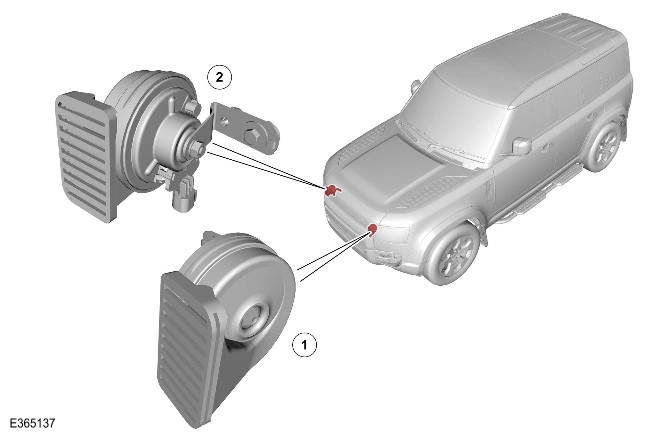
E365137

ItemDescription
1Horn - Left
2Horn - Right

The vehicle horns are located above the front bumper armature. The horns have a switched power supply through the horn relay located in the Engine Junction Box (EJB). The horns are switched through the steering wheel, connected through the clockspring to the BCM/GWM. The BCM/GWM activates the horns as a secondary security sounder when the alarm is triggered.

Volumetric Sensor

NOTE:

RHD vehicle is shown, LHD vehicle is similar.
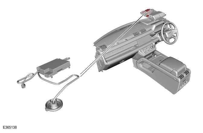
E365138

The volumetric sensor is located in a central position in the overhead console. The volumetric sensor comprises 3 sensors which allow the passenger compartment to be monitored. The Passenger Junction Box (PJB) provides a permanent power supply for the volumetric sensor. The sensor signals are transmitted to the BCM/GWM assembly on LIN.

DL vehicles

The volumetric sensors are activated when the vehicle is double locked. The vehicle can be locked and alarmed with the volumetric sensors deactivated. The volumetric sensors can be achieved by single locking the anti-theft active system or by deactivating in the IPC settings menu:

  • Single locking the anti-theft active system.
  • Deactivating the alarm sensors in the IPC settings menu.

Single locking

In certain markets the volumetric sensors are activated on single locking as a market requirement.

The volumetric sensors are active when the startup battery voltage falls below 9V. The BCM/GWM assembly ignores any inputs from the sensors to prevent false alarm activation.

The BCM/GWM ignores the signals from the volumetric sensor for the first 15 - 30 seconds. The time allows the vehicle interior to settle and prevents false alarm activation.

When the tailgate is opened through the smart key, the volumetric sensor and the tilt sensor are inhibited until the tailgate is closed.

Hood Switch

The hood switch is attached to the underside of the left hood latch and operated by movement of the latch mechanism. When the hood latch opens, the switch closes and connects a ground to the BCM/GWM.

Smart key
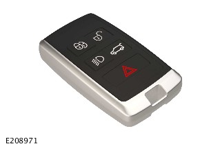
E208971

For additional information, refer to: Handles, Locks, Latches and Entry Systems (501-14 Handles, Locks, Latches and Entry Systems, Description and Operation).

PEPS

The PEPS system includes enhancements to further improve vehicle security.

The smart key includes ultra wide band technology, designed to combat the latest security threats. Ultra wide band technology includes 2 new passive entry transceivers which are programed to the vehicle in conjunction with smart keys.

NOTE:

The smart key does not need to be held adjacent to the IAU. The function is still supported to cover error states.

The RF receiver is equipped at the rear behind of the sunroof panel.

For additional information, refer to: Anti-Theft - Passive (419-01B Anti-Theft - Passive, Description and Operation).

OPERATION

Disarming

The BCM/GWM automatically arms and disarms the anti-theft system when it operates the CDL system. The BCM/GWM also locks and unlocks the Electric Steering Column Lock Control Module (VIM) when it operates the CDL system.

On vehicles without a volumetric sensor, only the perimeter mode is available to monitor the hinged panels and the validity of the smart key.

When perimeter sensing is active, the BCM/GWM monitors aperture ajar switches. The ajar switches are located in the latch mechanisms of the doors, in the tailgate and the hood latch.

When volumetric sensors are active, the BCM/GWM monitors the passenger compartment for movement using a volumetric sensor located on the front overhead console.

When the tilt sensors are active, the BCM/GWM monitors the vehicle for raising using a tilt sensor located within the BBUS.

Arming

Perimeter mode

The anti-theft active system is armed in the perimeter mode when the vehicle is either locked or double locked. The locked or double locked is locked using the lock switch on the smart key. The vehicles have the function of the the passive entry system. The anti-theft active system is armed in the perimeter mode when the lock/unlock switch on 1 of the exterior door handles is used.

Smart key switch selection and the lock/unlock switch selection on the exterior door handles are relayed to the BCM/GWM. The signal is sent by the RFA on the High Speed (HS) Controller Area Network (CAN) body systems bus.

Perimeter mode only monitors the hinged panels and the validity of the smart key in the RFA.

Perimeter with alarm sensing mode

The volumetric sensor monitors the vehicle interior for intrusion. The vehicle is equipped with a BBUS which incorporates a tilt sensor. The vehicle attitude is also monitored when perimeter with alarm sensing mode is active.

Perimeter with alarm sensing mode is activated by the following manner:

  • A second press of the lock switch on the smart key.
  • Using the lock switch on 1 of the exterior door handles, on vehicles with the passive entry system.

The second press of the switch must occur within 3 seconds of the first press. The second press of the lock switch also activates the perimeter sensing double locking feature.

In certain markets the volumetric sensors are activated on single lock as per latest market requirements.

The BCM/GWM arms the active anti-theft system when it single locks or double locks the vehicle, providing all the following conditions are met:

  • All doors, tailgate and hood are closed.
  • The BCM/GWM is not in transit mode.

When the vehicle successfully completes its locking routine, a single short flash of the turn signal indicators to indicate a single locked condition.

When double locking is activated, then the confirmation is given by:

  • A double flash of the turn signal indicators.
  • The 1 short flash for locked.
  • The 1 long flash on completion of double locked.

When ‘audible lock warning’ is enabled, an audible chirp shall also be emitted from BBUS on double lock. The feature can be turned on and off in the IPC security features menu.

Mislock

When a lock or double lock request is received from a smart key, the anti-theft alarm remains disarmed when:

  • Any doors, tailgate or hood is open/ajar.
  • Power Mode 6 (ignition ON).

The BCM/GWM generates a short mislock sound from the BBUS, or the passive sounder. The turn signal indicators does not flash. Each attempt to lock, is confirmed by an audible chime being emitted.

The volumetric sensor and the tilt sensor in the BBUS are inhibited until the tailgate is closed.

Disarming

The BCM/GWM disarms the active anti-theft system to prevent false alarm activation under certain conditions as follows:

  • The system is in perimeter with alarm sensing mode and the startup battery voltage decreases to less than 9V. The BCM/GWM disables the perimeter with alarm sensing mode. The BCM/GWM remains in perimeter mode only. The BCM/GWM prevents false alarm activation because the volumetric sensor cannot operate correctly below 9V.
  • The BCM/GWM deactivates the BBUS when the startup battery voltage decreases from 9.5V to 9V in more than a 30 minutes period. When required, the BCM/GWM activates the horns to sound an audible alarm trigger warning. At voltages below 9V, the BCM/GWM does not generate the 'heartbeat' signal to the BBUS. The BBUS interprets this as the BCM/GWM has been tampered with and activates its sounder. When the startup battery voltage subsequently rises to more than 9.5V, the BCM/GWM re-arms the BBUS.
  • The vehicle automatically re-locks and re-arms the active anti-theft system when unlocking the vehicle and within 40 seconds a hinged panel is not opened. The function prevents leaving the vehicle unlocked and disarmed by accidental operation of the smart key unlock switch/exterior handle.

Alarm

When the alarm is triggered, the BCM/GWM activates audible and visual warnings. The audible warnings are produced by the passive sounder or the BBUS and horns. Visible indications are produced using the turn signal indicators.

The BCM/GWM activates below components:

  • Passive sounder or the BBUS
  • The horns
  • The visual indications.

The BCM/GWM activates components for 30/60 seconds, depending on the market.

The activation is stopped for 10 seconds. When the alarm trigger is still present, the BCM/GWM cycles again for 30/60 seconds. The activation repeats for up to a maximum of 10 cycles per trigger source of 30/60 seconds for any 1 arming period.

NOTE:

When the BBUS is triggered due to tamper detection, the visual indication using the turn signal and horns are not activated.

The alarm can be triggered by:

  • Any of the hinged panels being opened.
  • Any of the doors being unlocked.
  • The volumetric sensor detects a movement inside the vehicle.
  • The tilt sensor detects vehicle movement.
  • An ignition tamper is detected (invalid smart key).

BBUS

NOTE:

When a BBUS is equipped, it is also armed with the perimeter mode lock request. However, the tilt functionality is not enabled in perimeter mode depending on market/single/double locking latches.

On receipt of the arming signals, the BBUS and the tilt sensor respond with a status message. When the BCM/GWM does not receive the status signals within a period of time, there is a fault in the system. The BCM/GWM responds with a disarm signal to either the sounder and/or the tilt sensor and stores a related DTC. The sounder is disarmed when the active anti-theft system is armed and the system is subsequently triggered. The BCM/GWM still energizes the horn relay and uses the vehicle horns to sound the audible warning in place of the BBUS.

When the BBUS is armed, the BCM/GWM sends a periodic (heartbeat) signal to the BBUS. The signal prompts the BBUS to monitor the vehicle startup battery supply and the LIN with the BCM/GWM.

The BBUS operates in the following cases:

  • The BBUS receives an alarm signal from the BCM/GWM or the tilt sensor.
  • The power supply or the LIN to the BCM/GWM is disrupted.

The tilt sensor measures the longitudinal and lateral angle of the vehicle over a range of of ±16° from the horizontal. When the active anti-theft system is armed in perimeter with alarm sensing mode, the tilt sensor:

  • Stores the current vehicle angles in its memory.
  • Monitors the tilt sensor readings.

When the vehicle angle changes in either direction by more than the alarm limit threshold, the tilt sensor communicates to the BCM/GWM. The BCM/GWM activates the BBUS.

When the alarm is active and the battery or the BBUS is disconnected, the BBUS continues to sound without the turn signal indicators flashing or horn.

Panic alarm

A panic alarm feature allows the vehicle alarm to be activated using the smart key. The panic alarm switch, identified by a triangle symbol, can be operated and held for more than 3 seconds to activate the vehicle alarm.

To cancel the panic alarm feature perform 1 of the following:

  • Operate the panic alarm switch 3 times.
  • Press and hold the panic switch for 3 seconds.
  • Operate the ignition switch.

To prevent accidental cancellation, the panic alarm cannot be canceled within 5 seconds of being activated.

Smart key additional features

In addition to the lock and unlock switches, the smart key has convenience switches.

Headlamp convenience

A headlamp convenience switch can be pressed to operate the headlamps to assist departure or approach to the vehicle. A single press of the switch operates the headlamps for approximately 25 seconds, after which time they turn OFF automatically. A second press of the switch, switches OFF the headlamps when the 25 seconds period has not been reached. Operating the ignition switch within the 25 seconds period, also turns OFF the headlamp convenience feature.

Convenience mode

When the vehicle is unlocked using the unlock switch on the smart key, the vehicle electrical system initiates convenience mode.

The following systems become active in convenience mode:

  • Memory - Seat adjustment and mirror position.
  • Interior and exterior lighting.
  • Audio system.
  • IPC message center.
  • Horn.
  • 12V accessory socket.

Single point entry

The single point entry feature only unlocks the driver door, all other doors remain single locked. A single press of the unlock switch on the smart key, only unlocks the driver door. A second press is required to unlock the remaining doors and the tailgate.

When the vehicle is double locked, the first press of the unlock switch on the smart key unlocks the driver door.

The remaining doors revert to the single locked state and can be unlocked using the following:

  • A further press of the smart key unlock switch.
  • The CDL lock/unlock switch on the driver door.
  • The interior door handles on the passenger doors.
  • Passive entry through any passenger door.

Access to the tailgate can be achieved through:

  • A further press of the smart key unlock switch.
  • The smart key tailgate open switch.
  • The CDL lock/unlock switch on the driver door.
  • The interior door handles on the passenger doors.
  • Passive entry through any passenger door.
  • Passive entry through the tailgate open switch.

Changing from CDL to single point entry can be done by:

  • Pressing the lock and unlock switches on the smart key simultaneously. The turn signal indicators flash to confirm that the function change has been performed.
  • Using the IPC menu.

Global open/close

NOTE:

The global open/close feature is not available in all markets.

A global open and close feature can be operated from the smart key. The feature allows the vehicle windows to be opened/closed through a single press of the lock or unlock switch. The switch must be pressed and held for more than 2 seconds to activate the global open/close feature. The windows must be initialized for the global functionality to work.

Ultra Wide Band Operation

With the introduction of ultra wide band technology, recognizing the position of the smart key requires 2 pieces of distance information. The 2 passive entry transceivers are located in the headliner, 1 at the front and 1 at the rear. The passive entry transceivers enable full coverage inside and outside of the vehicle.

The following process takes place to validate the smart key:

  • The RFA receives a door lock/unlock request.
  • On receipt of the door lock/unlock request, challenge data is sent out from the RFA. The challenge data is sent through LF antenna at 125 kHz to the smart key.
  • The smart key responds to the LF signal, processing the received message and replying to the vehicle using a separate RF channel. Depending on market the RF channels are 433 MHz or 315 MHz.
  • The response is received by the RF receiver.

In addition the RFA sends a separate challenge, through the passive entry transceivers to the smart key. The RFA sends this data to authenticate and obtain the smart key position with accuracy, using the following process:

  • The challenge data is sent from the RFA through LIN to the passive entry transceivers.
  • The passive entry transceivers process and transmit the data, through a separate RF signal, at 3.99 GHz (4.5 GHz in China) to the smart key.
  • On receipt of the signal the smart key responds with an authentication message back to the passive entry transceivers. The smart key responds by a RF signal through the LIN connection.

When the smart key is validated the system operates normally.

LF Zones
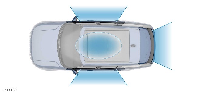
E213189

The message contained in the beacon signals varies based on each transmitter zone. For example, the message varies based on if the zone is:

  • Inside or outside the vehicle.
  • The driver side or passenger side or the loadspace.

The capability allows the smart key to send specific answers, triggering actions such as opening the passenger door or starting the engine.

A common security threat consists of relaying the messages exchanged between the vehicle and the smart key over long distances. The message range is indefinite, depending on the technology used. The technology is used by intercepting the beacon signal from the LF antenna in the vehicle to the smart key.

The equipment intercepts the messages is used to gain illegal entry to the vehicle and activate the passive start system.

For additional information, refer to: Anti-Theft - Passive (419-01B Anti-Theft - Passive, Description and Operation).

DIAGNOSTICS

The BCM/GWM records any DTCs and related data. Read the DTCs and related data with the JLR approved diagnostic equipment.

The JLR approved diagnostic equipment can read live data and activate certain components.

CONTROL DIAGRAM

CONTROL DIAGRAM - 1 of 2
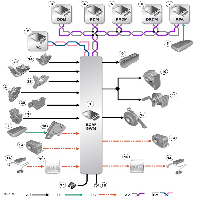
E365139

A = Hardwired: F = RF transmission: O = LIN: AZ = HS CAN bus: BA = HS CAN Human Machine Interface (HMI) systems bus.

ItemDescription
1BCM/GWM
2IPC
3DDM
4PDM
5PRDM
6DRDM
7RFA
8Smart Key
9IPC - Security system status indicator
10Horn - Left
11Horn - Right
12Passive sounder - If equipped
13BBUS - If equipped
14Volumetric sensor
15Overhead console
16Ground
17Power supply
18IAU
19Ajar switch - Tailgate
20Hood switch
21Ajar switch - Front left door
22Ajar switch -Front right door
23Ajar switch - Rear left door
24Ajar switch - Rear right door

Control Diagram - 2 of 2 - Smart Key Recognition and Detection
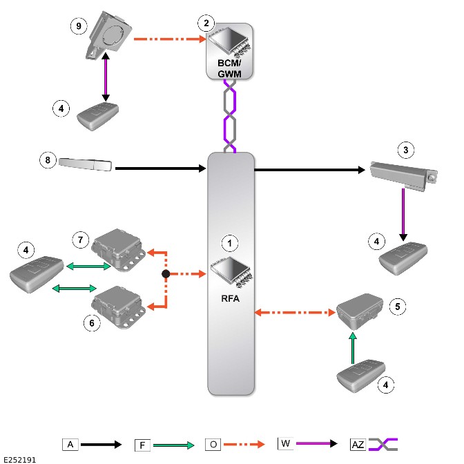
E252191

A = Hardwired: F = RF transmission: O = LIN: W = LF transmission: AZ = HS CAN body systems bus.

ItemDescription
1RFA
2BCM/GWM
3LF antenna (quantity 5)
4Smart key
5RF receiver
6Passive entry transceiver - Front
7Passive entry transceiver - Rear
8Lock/unlock request - Door handle
9IAU


Principles of Operation

Vehicle Immobilizer Control Module (VIM)

For a detailed description of the anti-theft - active operation, refer to the relevant description and operation section of the workshop manual. REFER to: Anti-Theft - Active (419-01A Anti-Theft - Active, Description and Operation).

Inspection and Verification

CAUTION:

Diagnosis by substitution from a donor vehicle is NOT acceptable. Substitution of control modules does not guarantee confirmation of a fault, and may also cause additional faults in the vehicle being tested and/or the donor vehicle

NOTES:

  • Guided Diagnostics must be followed and the repair advised by the process completed. Failure to do so may result in the rejection of any warranty claim made.
  • If a control module or a component is at fault and the vehicle remains under manufacturer warranty, refer to the Warranty Policy and Procedures manual, or determine if any prior approval program is in operation, prior to the installation of a new module/component.
  • When performing voltage or resistance tests, always use a digital multi meter that has the resolution ability to view 3 decimal places. For example, on the 2 volts range can measure 1mV or 2 K Ohm range can measure 1 Ohm. When testing resistance always take the resistance of the digital multi meter leads into account.
  • Check and rectify basic faults before beginning diagnostic routines involving pinpoint tests.
  1. Verify the customer concern
  1. Visually inspect for obvious signs of damage and system integrity

Visual Inspection

MechanicalElectrical
  • Start/stop switch
  • Electric steering column lock
  • Smart key
  • Fuses
  • Electrical harnesses
  • Harness connectors
  • Smart key battery
  • Body Control Module (BCM, controls +12 volt supply to the vehicle immobilizer control module and software logic for the vehicle immobilizer column lock control)
  • Remote Function Actuator (RFA)
  • Radio Frequency (RF) receiver
  • Instrument pack (provides electrical ground circuit to the vehicle immobilizer control module)
  • Volumetric sensor
  • Controller Area Network (CAN) circuits
  • Vehicle Immobilizer Control Module (VIM)
  1. If an obvious cause for an observed or reported concern is found, correct the cause (if possible) before proceeding to the next step
  1. If the cause is not visually evident check the system for any set diagnostic trouble code(s) and proceed to the Diagnostic Trouble Codes (DTC) index
  1. Check Jaguar Land Rover claims submission system for open campaigns. Refer to the corresponding bulletins and SSMs which may be valid for the specific customer complaint and complete the recommendations as required

Symptom Chart
SymptomPossible CauseAction
False alarm triggers - Volumetric sensor identified as last known alarm trigger
  • Genuine movement detected, no further action required
  • Water ingress into the volumetric sensor/connectors
  • Poor installation of the volumetric sensor (false trigger)
  • Sensor internal failure
NOTES:
  • Confirm if the vehicle has been checked previously for the same concern or wether this is the first visit to a retailer
  • Make sure to take a recording of the alarm trigger history and add this to the warranty claim
  • Check with the customer to establish wether the vehicle is parked near air force bases or other locations where the vehicle could be subject to loud noises (jets flying overhead, tractors driving very close by)
  • Inspect the area of the volumetric sensor for any evidence of water leaks and rectify as necessary
  • Check the installation of the volumetric sensor, remove and reinstall the sensor making sure all connections are secure and the sensor is correctly installed
  • If there have been repeat visits for false alarm triggers install a new volumetric sensor
"Smart Key Not Recognized, Reposition or Place As Shown and Press Start Button” message displayed on the Instrument Panel Cluster Control Module (IPC)NOTE:

The message guides the customer to place the smart key adjacent to the close proximity antenna as a backup

  • The smart key cannot be found by the passive start system within the vehicle
  • Smart key obscured from detection by metallic objects
  • Passive start system fault
  • Low battery in the smart key
  • Smart key internal failure
  • If the smart key is not recognized measure the voltage of the smart key battery. If the voltage is below 2.9 volts, install a new battery
  • Using the Jaguar Land Rover (JLR) approved diagnostic equipment use the fault and breakdown workflow.
  • To navigate to the guided flow select – ‘Guided Diagnostics’/’Warnings’/’Messages’/Smart Key not found’
Smart Key inoperative - Insufficient or no power to the smart key
  • Smart key battery upper positive terminal has lifted, due to unnecessary force applied when replacing the battery. As such, there is not enough pressure on the battery with the negative terminal
  • Remove the battery and press the upper positive terminal until the negative grid is touched. Upon recovering the position of the terminal, the coin cell shall have firm positive contact with the upper terminal
  • If the fault persists, continue with the usual diagnostic steps to determine the faulty system component.
E292590

Correct Installation Of The Volumetric Sensor

The volumetric sensor is located in a central position in the overhead console. The volumetric sensor allows the interior of the vehicle to be monitored when the vehicle is double locked. In cases where customers have reported "false-alarm" triggers of the vehicle anti-theft alarm and where the volumetric sensor has been identified as the last known alarm trigger (see diagnostic instructions below), this may indicate an issue with the installation of the volumetric sensor rather than an internal failure of the sensor itself.
E267020

In light of this, when first faced with this issue, the existing volumetric sensor should be carefully removed and refitted. Care should be taken to make sure that the sensor and associated connectors are installed correctly and securely. See illustration and video for correct installation, when installed conduct 'push-pull-push' on connections to make sure of correct engagement. Make sure the sensors are pushed fully home and abut against the console, there should be equal placement all around the sensor and it should not be angled when compared to the surface of the console, no large visible gap should be seen and any small gap should be equal all around the sensor when viewed from the front and the rear of the console, use a flashlight to aid with gap visibility, REFER to: Overhead Console (501-12 Instrument Panel and Console, Removal and Installation).

If the issue reoccurs after refitting of the volumetric sensor, then the sensor should be replaced.

READING ALARM TRIGGER HISTORY THROUGH TOPIx Cloud Diagnostics.

NOTE:

Make sure to take a recording of the alarm trigger history and add this to the warranty claim

To determine the details of recent anti-theft alarm triggers on JLR approved diagnostic vehicles, the following steps should be followed:

  1. Using the Jaguar Land Rover approved diagnostic equipment, connect to the vehicle through the Vehicle Communication Interface (VCI) unit
  1. Load in the Vehicle Identification Number (VIN)
  1. SELECT 'ECU Diagnostics'
  1. SELECT 'Body Control Module (BCM)'
  1. SELECT 'ECU Functions From List'
  1. SELECT 'Alarm Trigger History' and follow on-screen instructions to view recent alarm trigger history

DTC Index

For a complete list of all diagnostic trouble code(s) that could be set on this vehicle, please refer to Section 100-00. REFER to: Diagnostic Trouble Code Index - DTC: Remote Function Actuator (RFA) (100-00 General Information, Description and Operation) / Diagnostic Trouble Code Index - DTC: Vehicle Immobilizer Control Module (VIM) (100-00 General Information, Description and Operation) / Diagnostic Trouble Code Index - DTC: Body Control Module (BCM) (100-00 General Information, Description and Operation).


Anti-Theft - Passive (G2881055)

DESCRIPTION AND OPERATION

COMPONENT LOCATION

Component Location - 1 Of 4

NOTE:

Right Hand Drive (RHD) vehicle is shown, Left Hand Drive (LHD) vehicle is similar.
E252182

ItemDescription
1Immobilizer Antenna Unit (IAU)
2Ignition switch
3Body Control Module (BCM)/Gateway Control Module (GWM)

Component Location - 2 Of 4

NOTES:

  • RHD vehicle is shown, LHD vehicle is similar.
  • Vehicle with 5 doors is shown, Vehicle with 3 doors is similar.
E252183

ItemDescription
1Radio Frequency (RF) receiver
2Remote Function Actuator (RFA)

Component Location - 3 Of 4

NOTES:

  • RHD vehicle is shown, LHD vehicle is similar.
  • Vehicle with 5 doors is shown, Vehicle with 3 doors is similar.

E252189

ItemDescription
1Low Frequency (LF) - Front passenger compartment
2LF - Right passenger compartment
3LF - Left luggage compartment
4LF - Rear passenger compartment - Only for passive start system
5LF - Left passenger compartment

Component Location - 4 Of 4

NOTES:

  • RHD vehicle is shown, LHD vehicle is similar.
  • Vehicle with 5 doors is shown, Vehicle with 3 doors is similar.

E252185

ItemDescription
1Passive entry transceiver - Front
2Passive entry transceiver - Rear

OVERVIEW

The passive start system relies on the detection of a uniquely coded smart key through LF antennas strategically situated within the vehicle. The LF antennas sense when the smart key is in the active transmission zone of the LF antennas. The transmission zone allows the smart key to be detected inside the vehicle. For this reason the orientation and position of the antennas is critical to the correct functioning of the system. The smart key also operates the passive entry system.

For additional information, refer to: Handles, Locks, Latches and Entry Systems (501-14 Handles, Locks, Latches and Entry Systems, Description and Operation).

The passive start system provides a secure interface between the BCM/GWM and the Powertrain Control Module (PCM). The interface prevents unauthorized starting of the engine. Encoded data exchange between the smart key and multiple control modules immobilizes the engine crank system and the fuel system.

Engine starting is initiated when the encoded data exchange between the smart key and the control modules is verified. The engine management system then allows engine crank and fueling when an authorization data message is received from the BCM/GWM.

The engine can be started by pressing the ignition switch when PARK (P) position is selected and the brake pedal is pressed.

DESCRIPTION

Low Frequency Antennas

NOTES:

  • RHD vehicle is shown, LHD vehicle is similar.
  • Vehicle with 5 doors is shown, Vehicle with 3 doors is similar.

E252189

ItemDescription
1LF - Front passenger compartment
2LF - Right passenger compartment
3LF - Left luggage compartment
4LF - Rear passenger compartment - Only for passive start system
5LF - Left passenger compartment

There are 5 LF antennas for the Passive Entry Passive Start (PEPS) system positioned in the following locations:

  • There is 1 LF antenna located in the front floor console.
  • There is 1 LF antenna located in each rear door (quantity 2).
  • There is 1 LF antenna located beneath the third row seats, the antenna only for passive start system.
  • There is 1 LF antenna located behind the rear bumper.

The RFA transmits a LF signal through the antennas which is received by the smart key. The smart key then responds by transmitting a RF signal which is received by the RF receiver. The RF receiver sends the signal to the RFA.

RFA

NOTES:

  • Vehicle with 5 doors is shown. Vehicle with 3 doors is similar.
  • Before you configure a new RFA, put ALL the vehicle keys on the center console.
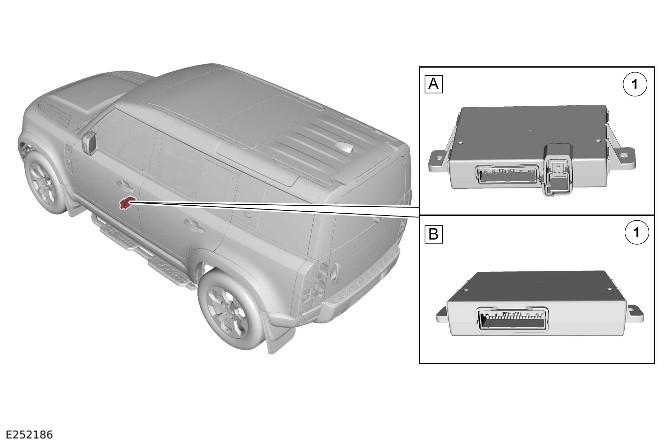
E252186

ItemDescription
AVehicles with PEPS system
BVehicles with passive start system
1RFA

The RFA is located in the below of the front left seat.

The RFA controls signal transmissions to and from the smart key and provides authorization to allow the vehicle to be unlocked and started. The RFA has a High Speed (HS) Controller Area Network (CAN) body systems bus connection to the BCM/GWM.

RF Receiver

NOTE:

Vehicle with 5 doors is shown. Vehicle with 3 doors is similar.
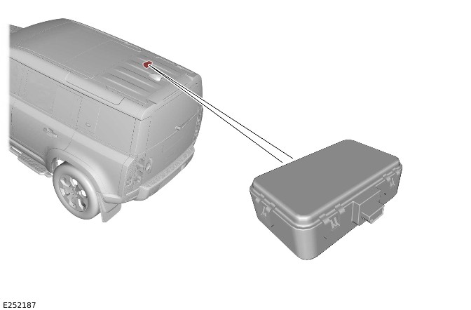
E252187

The RF receiver is located in the rear headliner.

The RF receiver receives RF signals from the smart key. When the RF receiver receives a signal from the smart key, the RF receiver passes the signal to the RFA.

There are 2 types of RF receiver available as detailed in the table below.

Part No. suffixOperating frequencyVehicle specification
A#315 MHzNorth American Specification (NAS), Japan and Korea
B#433 MHzEurope and Rest of World (ROW)

IAU

NOTE:

RHD vehicle is shown, LHD vehicle is similar.
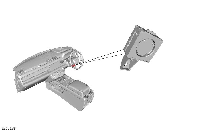
E252188

The IAU is installed underneath the lower steering column cover and secured with a bolt, for both auto and manual columns.

The IAU is used when the RFA is unable to authorize the smart key.

The RFA is unable to identify the smart key when the smart key battery voltage is low or there is RF interference.

The transponder within the smart key can be read in the conventional manner.

The driver is alerted to this by an audible chime and a message is displayed in the Instrument Panel Cluster (IPC). The message is 'Place Smart Key as shown, and press start button'.

Passive Entry Transceiver

NOTES:

  • RHD vehicle is shown, LHD vehicle is similar.
  • Vehicle with 5 doors is shown, Vehicle with 3 doors is similar.

E252185

ItemDescription
1Passive entry transceiver - Front
2Passive entry transceiver - Rear

There are 2 passive entry transceivers in a vehicle, 1 in the front headliner and the other in the rear of the headliner. The passive entry transceivers are used to locate the position of the smart key from the vehicle. The passive entry transceivers communicate with the RFA through a Local Interconnect Network (LIN). Each passive entry transceiver has a power supply from the Rear Junction Box (BCMB) and a ground connection. When the passive start sequence is initiated and a smart key is detected, the passive entry transceivers calculate the distance of the smart key. Then the RFA allows the authorization of the smart key only when this distance is within permissible limits.

NOTE:

The passive entry transceivers are only equipped on PEPS vehicles, and ultra wide band in permitted markets. When the passive entry transceivers are not equipped, the RFA performs the smart key authentication through LF challenge to the smart key. The responses from the smart key are received through the RF receiver.

The passive entry transceivers are also involved with the passive entry system.

For additional information, refer to: Handles, Locks, Latches and Entry Systems (501-14 Handles, Locks, Latches and Entry Systems, Description and Operation).

Activity Key - If Equipped

NOTE:

When the vehicle is locked with the activity key, any valid smart key remaining inside the vehicle is disabled. Any valid smart key outside the vehicle remains enabled.
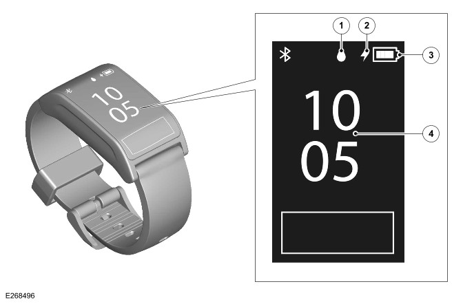
E268496

ItemDescription
1Water lock symbol
2Charge symbol
3Charge status
4Home screen

The activity key is a touch display with wrist strap. The activity key is designed to support situations where the smart key might be obtrusive or difficult to keep secure. The activity key is waterproof to a depth of 40 m (131 ft) and is shockproof. Care should be taken during certain sporting activities.

The activity key provides full functionality of PEPS.

When the activity key is worn on the wrist, the smart key can remain inside the vehicle, but it is not mandatory. When the activity key is activated, the vehicle locks, the security system arms, and the PEPS functions are disabled for any smart key, remaining inside the vehicle.

The activity key uses the same technology for authentication and signal transmission with the RFA as the smart key. The LF signals from the LF antennas are initiate the authentication process. The activity key responds with a RF signal, which is transmitted to the RFA through the RF receiver. The passive entry transceivers are also activated to calculate the distance of the activity key from the vehicle.

The activity key for each vehicle specification is identified by a suffix change to the base part number as follows:

Part No. SuffixOperating FrequencyVehicle Specification
A#315 MHzNAS and Japan
B#433 MHzEurope and ROW

PEPS System

NOTE:

The smart key does not need to be held adjacent to the IAU. However this function is still supported to cover error states.

The PEPS system includes enhancements to further improve vehicle security.

The smart key includes ultra wide band technology. Ultra wide band technology includes 2 new passive entry transceivers, which are programed to the vehicle in conjunction with smart keys.

OPERATION

Passive Start System

The RFA prompts each of the internal LF antennas to output a signal. When the smart key is in the passenger compartment, the smart key detects the LF signals. The smart key responds with a data identification signal back to the RF receiver. The RF receiver sends the data identification signals to the RFA.

In addition the RFA sends a separate challenge, through the passive entry transceivers to the smart key. The RFA sends this data to authenticate and obtain the smart key position with accuracy.

When the data received matches that stored in the RFA, the RFA continues the passive start process by communicating a 'smart key valid' signal. The valid signal is received by the BCM/GWM through the HS CAN body systems bus.

The BCM/GWM receives the authorization and confirms the response with an internal calculation. The BCM/GWM passes coded data to the IPC on the HS CAN Human Machine Interface (HMI) systems bus. Upon confirmation from the IPC, Power Mode 6 (ignition ON) is enabled.

The BCM/GWM exchanges encrypted data with the Electric Steering Column Lock Control Module (VIM) mechanism. The data authorizes the unlocking of the steering column. The IPC only provides a ground for the VIM motor. The BCM/GWM then sends a mobilization signal to the PCM.

The BCM/GWM enables the fuel pump relay which provides a startup battery voltage supply to the Fuel Pump Driver Module (FPDM).

When the RFA fails to locate the smart key, a message is displayed in the IPC message center. The message is 'Place Smart Key as shown, and press start button'.

The keyless start backup process must be used to mobilize and start the vehicle.

Passive Start Backup

When the vehicle is unlocked with the emergency key or the vehicle does not detect a smart key. Using the passive start backup procedure is then necessary for the following:

  • Disarm the alarm
  • Start the engine.

The following passive start backup process must be followed in this event:

  • Pressing the ignition switch when the RFA fails to locate the smart key. 'Place Smart Key as shown, and press start button' appears in the IPC message center.
  • For vehicles with a manual or powered steering column, position the smart key under the lower steering column cowl. The switches on the smart key must face outwards.
  • Pressing the ignition switch with the brake pedal pressed to start the engine.

NOTE:

When the 'Place Smart Key as shown, and press start button' message is no longer displayed (only displayed for 10 seconds), the sequence has to be repeated.

The process bypasses the data exchange between the RFA and the BCM/GWM. The process is an inductive process and operates even if the battery in the smart key is discharged. A transponder within the smart key is detected by the IAU. The IAU communicates this code with the BCM/GWM through a LIN connection. The BCM/GWM then initiates the vehicle start process in the normal manner.

Ultra Wide Band Operation

With the introduction of ultra wide band technology, recognizing the position of the smart key requires 2 pieces of distance information. The 2 passive entry transceivers are located in the headliner, 1 at the front and 1 at the rear. The passive entry transceivers enable full coverage inside and outside of the vehicle.

The following process takes place to validate the smart key:

  • The RFA receives a door lock/unlock request.
  • When the RFA receives the door lock/unlock request, it sends out the challenge data through the LF antenna to the smart key. The data is sent at 125 kHz.
  • The smart key responds to the LF signal, processing the received message and replies to the vehicle using a separate RF channel. Depending on market the RF channels are 433 MHz or 315 MHz.
  • This response is received by the RF receiver.

In addition the RFA sends a separate challenge, through the passive entry transceivers to the smart key. The RFA sends this data to authenticate and obtain the smart key position with accuracy, using the following process:

  • The challenge data is sent from the RFA through a LIN to the passive entry transceivers.
  • The passive entry transceivers process and transmit the data, through a separate RF signal, at 3.99 GHz (4.5 GHz in China) to the smart key.
  • On receipt of the signal the smart key responds with an authentication message back to the passive entry transceivers. The smart key responds by a RF signal through the LIN connection.

When the smart key is validated the system operates normally.

Low Frequency Zones

E213189

The message contained in the beacon signals varies based on each transmitter zone. For example, the message varies based on when the zone is:

  • Inside or outside the vehicle.
  • The driver side, passenger side or the loadspace.

The capability allows the smart key to send specific answers, triggering actions such as opening the passenger door or starting the engine.

Diagnostics

The BCM/GWM records any Diagnostic Trouble Code(s) (DTC) and related data. The DTC and related data are read using the Jaguar Land Rover (JLR) approved diagnostic equipment.

The JLR approved diagnostic equipment enables certain components to be activated and also read live data.

Activity Key - If Equipped

Activity Key Locking

The vehicle must be in Power Mode 4 or below (ignition OFF). After exiting the vehicle and closing any open door, swipe upward to access the activity key 'Locking menu'. Touch the lock symbol to lock the vehicle.

When the security authentication is complete, the vehicle locks and arms the security system. The hazard warning lamps flash to confirm. If the power fold door mirrors are enabled, the door mirrors fold in. Touch the home symbol on the activity key screen to return to the home screen.

Activity Key Unlocking

When returning to the vehicle, swipe upward to access the activity key 'Locking menu' and touch the unlock symbol. When the security authentication is complete, the vehicle unlocks and disarms the security system. The hazard warning lamps flash to confirm. If the power fold door mirrors are enabled, the door mirrors unfold.

Other Activity Key Functions

The activity key can also be used as follows:

  • Select the settings menu to change the activity key displayed time. Select the clock symbol, and adjust the time using the up/down arrows as desired.
  • Tailgate opening
  • To sound the panic alarm, briefly touch the screen 3 times in quick succession.
  • Select the water drop symbol to enable Water lock on the activity key. In Water lock mode all screen functionality is blocked to prevent any inadvertent operation when the activity key submerged into water. Touch the screen 4 times within 2 seconds to disable Water lock mode.

The activity keys can be configured to have the same profile as a standard smart key, so it must be programed and configured to the vehicle as a separate key, using the application on the Jaguar Land Rover (JLR) approved diagnostic equipment.

The activity key is charged using the USB cable suppled with the item.

CONTROL DIAGRAM

Control Diagram - 1 Of 2 - Passive Start
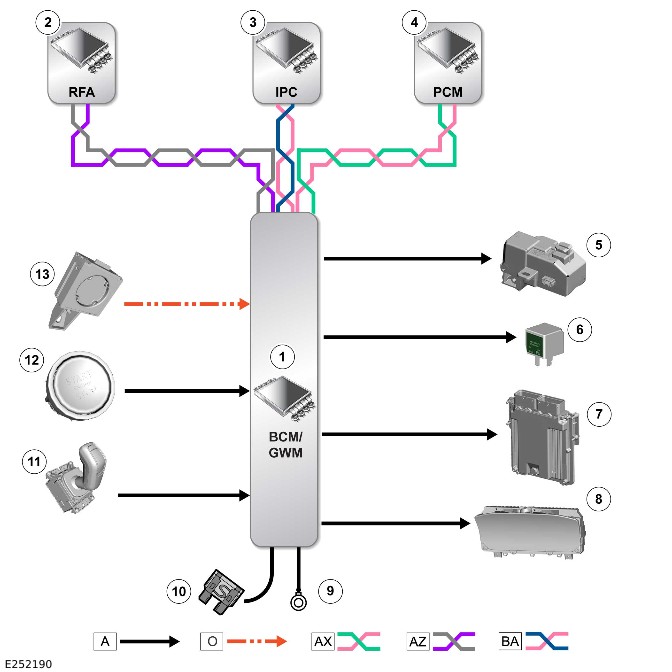
E252190

A = Hardwired: O = LIN: AX = FlexRay: AZ = HS CAN body system bus: BA = HS CAN HMI system bus.

ItemDescription
1BCM/GWM
2RFA
3IPC
4PCM
5VIM
6Fuel pump relay
7PCM
8IPC
9Ground
10Power supply
11Transmission Control Switch (TCS)
12Ignition switch
13IAU

Control Diagram - 1 of 2 - Smart Key Recognition and Detection
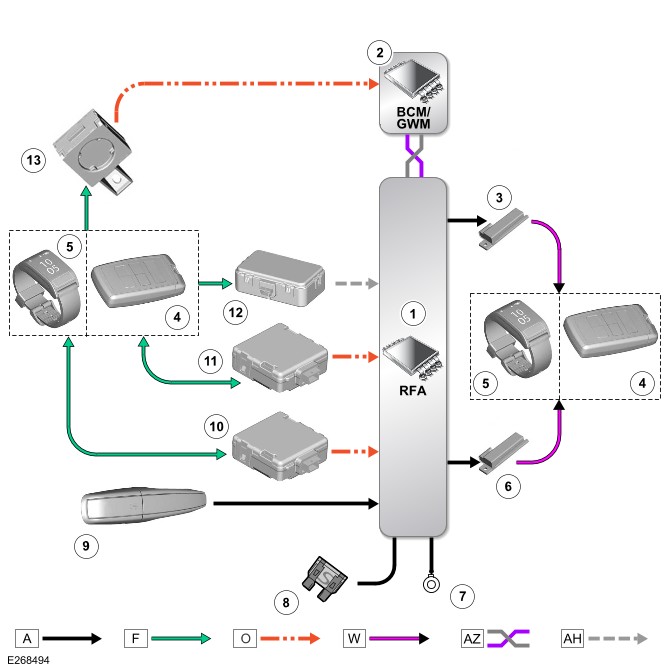
E268494

A = Hardwired: F = RF transmission: O = LIN: W = LF transmission: AZ = HS CAN body systems bus: AH = Serial Communication Line.

ItemDescription
1RFA
2BCM/GWM
3LF antenna - Floor console
4Smart key
5Activity key (if equipped)
6LF antenna - Loadspace
7Ground
8Power supply
9Door lock/unlock switch - Exterior door handle
10Passive entry transceiver - Front
11Passive entry transceiver - Rear
12RF receiver
13IAU

Remote Function Actuator Security Repair Information (G4569126)

DESCRIPTION AND OPERATION

Introduction

The technical guidance in this document supports the Remote Function Actuator (RFA) security repair procedures in TOPIx and gives a summary on Jaguar Land Rover (JLR) vehicle security configurations by region, requirements and/or parts required to complete security repairs, for example RFA, Body Control Module (BCM) or key replacements and software updates. It also includes requests to the customer for security related activities before the work is completed in the retailer, for example key(s) to be available and the status of the customers InControl© account.

Successful completion of the procedures will help decrease parts replacement and/or unnecessary costs for RFA security repairs.

APPLICABLE VEHICLES AND MODEL YEARS

The table below shows the vehicles and model years that this technical guidance is applicable to.

VehicleModel Year
Defender2020MY Onwards
Discovery Sport2021MY Onwards
Range Rover Evoque2021MY Onwards
Range Rover Velar2021MY Onwards
Range Rover2022MY Onwards
Range Rover Sport2023MY Onwards
E-PACE2021MY Onwards
I-PACE2021MY Onwards
XE2021MY Onwards
F-PACE2021MY Onwards

JLR vehicles have enhanced security measure available if -

  • The warranty start date is after 20th March 2024
  • RFA/BCM modules were replaced
  • Vehicle history shows Enhanced Security Campaigns (N888, N836 and N874) have been completed

GLOBAL RFA SECURITY REPAIRS

BEFORE Pre-Delivery Inspection (PDI)

ConcernService ActionMinimum RequirementsImportant InformationMarket
RFA and BCM are not locked1. Update RFA or BCM modulesLatest module software availableDo not replace modules. During PDI modules will be lockedGlobal
2. Program additional keys or activity key

UK, CHINA, OVERSEAS AND EUROPE RFA SECURITY REPAIRS

PDI AND SECURITY ENHANCEMENT CAMPAIGNS HAVE BEEN COMPLETED.

>td rowspan="1">UK, China, Overseas and Europe>td rowspan="1">UK, China, Overseas and Europe>td rowspan="1">UK, China, Overseas and Europe

ConcernService ActionMinimum RequirementsImportant InformationMarket
RFA and BCM are lockedRFA and BCM software update1 key and service mode enabled or all keys and activity keymust be replaced. Contact client and confirm their account is in service mode feature. This can be checked through InControl©
RFA or BCM are lockedReplace lost and/or broken key1 key and service mode enabled (Telematic Control Unit Module (TCU) must be at the latest software version) or 1 key and activity key (if it has been paired) must be inside the vehiclemust be replaced. Contact client and confirm their account is in service mode feature. This can be checked through InControl©
RFA or BCM are lockedProgram key (including activity key)1 key and service mode enabled or all keys and activity keymust be replaced. Contact client and confirm their account is in service mode feature. This can be checked through InControl©
Only RFA is lockedUpdate RFA software or program key1 key and service mode enabled or all keys and activity keyModules can be unlocked and updated in service mode. Contact client and confirm their account is in service mode feature. This can be checked through InControl©. If just one of the two requirements is available, only the RFA module must be replacedUK, China, Overseas and Europe
Only RFA is lockedReplace lost and/or broken key1 key and service mode enabled (TCU must be at the latest software version) or 1 key and activity key (if it has been paired) must be inside the vehicleContact client and confirm their account is in service mode feature. This can be checked through InControl©. If just one of the two requirements is available, only the RFA module must be replacedUK, China, Overseas and Europe
BCM renew. RFA locked. Software version L8B2-14C104-AP onwardsIf RFA software version is less than the AP level, update RFA software with all keys presentAll keys and activity keyContact client and confirm their account is in service mode feature. This can be checked through InControl©UK, China, Overseas and Europe
BCM renew. RFA locked. Software version L8B2-14C104-AP onwardsIf RFA software version is less than the AP level, update RFA software with all keys presentAll keys and activity key present or service mode (TCU must be at the latest software version)Contact client and confirm their account is in service mode feature. This can be checked through InControl©UK, China, Overseas and Europe
BCM locked. RFA has been replacedService mode must be activated so that the BCM can be synchronized with the new RFAService mode enabled (TCU must be at the latest software version)Contact client and confirm their account is in service mode feature. This can be checked through InControl©UK, China, Overseas and Europe

NORTH AMERICA RFA SECURITY REPAIRS

PDI AND SECURITY ENHANCEMENT CAMPAIGNS HAVE BEEN COMPLETED.

>td rowspan="1">North America>td rowspan="1">North America>td rowspan="1">North America

ConcernService ActionMinimum RequirementsImportant InformationMarket
SECURITY ENHANCEMENT CAMPAIGN HAS BEEN COMPLETED. RFA and BCM software updatedRFA and BCM software update1 key and service mode enabled or all keys and activity keymust be replaced. Contact client and confirm their account is in service mode feature. This can be checked through InControl©
SECURITY ENHANCEMENT CAMPAIGN HAS BEEN COMPLETED. RFA or BCM lockedReplace lost and/or broken key1 key and service mode enabled or 1 key and activity key (if it has been paired) must be inside the vehiclemust be replaced. Contact client and confirm their account is in service mode feature. This can be checked through InControl©
SECURITY ENHANCEMENT CAMPAIGN HAS BEEN COMPLETED. RFA or BCM lockedProgram key and activity key1 key and service mode enabled or all keys and activity keymust be replaced. Contact client and confirm their account is in service mode feature. This can be checked through InControl©
SECURITY ENHANCEMENT CAMPAIGN HAS BEEN COMPLETED. Replace BCM moduleFor RFA software update or program key1 key and service mode enabled or all keys and activity keyModules can be unlocked and updated in service mode. Contact client and confirm their account is in service mode feature. This can be checked through InControl©. If just one of the two requirements is available, only the RFA module must be replacedNorth America
SECURITY ENHANCEMENT CAMPAIGN HAS BEEN COMPLETED. Replace RFA moduleReplace faulty moduleService mode enable and all keysContact client and confirm their account is in service mode feature. This can be checked through InControl©. If just one of the two requirements is available, only the RFA module must be replacedNorth America


Anti-Theft - Passive (G2401030)

DIAGNOSIS AND TESTING

Principles of Operation

For a detailed description of the anti-theft - passive system and operation, refer to the relevant description and operation section of the workshop manual. REFER to: Anti-Theft - Passive (419-01B Anti-Theft - Passive, Description and Operation).

Inspection and Verification

CAUTION:

Diagnosis by substitution from a donor vehicle is NOT acceptable. Substitution of control modules does not guarantee confirmation of a fault, and may also cause additional faults in the vehicle being tested and/or the donor vehicle.

  1. Verify the customer concern
  1. Visually inspect for obvious signs of damage and system integrity

Visual Inspection

MechanicalElectrical
  • Start/stop button
  • Electric steering column lock
  • Vehicle key
  • Fuses
  • Electrical harnesses
  • Harness connectors
  • Vehicle key battery
  • Central junction box (controls +12Volt supply to electric steering column lock and software logic for electric steering column lock control)
  • Instrument cluster (provides electrical ground circuit to electric steering column lock)
  • Controller Area Network (CAN) circuits
  1. If an obvious cause for an observed or reported concern is found, correct the cause (if possible) before proceeding to the next step
  1. If the cause is not visually evident check for Diagnostic Trouble Codes (DTC)s and refer to the DTC index

Symptom Chart

SymptomPossible CausesAction
False alarm triggers - Volumetric sensor identified as last known alarm trigger
  • Genuine movement detected, no further action required
  • Water ingress into the volumetric sensor/connectors
  • Poor installation of the volumetric sensor (false trigger)
  • Sensor internal failure
NOTES:
  • Confirm if the vehicle has been checked previously for the same concern or wether this is the first visit to a retailer
  • Make sure to take a recording of the alarm trigger history and add this to the warranty claim
  • Check with the customer to establish wether the vehicle is parked near air force bases or other locations where the vehicle could be subject to loud noises (jets flying overhead, tractors driving very close by)
  • Inspect the area of the volumetric sensor for any evidence of water leaks and rectify as necessary
  • Check the installation of the volumetric sensor, remove and reinstall the sensor making sure all connections are secure and the sensor is correctly installed
  • If there have been repeat visits for false alarm triggers install a new volumetric sensor
Smart key operation - reduced range or intermittent operation
  • Smart key battery low voltage or depleted (no warning message for low battery displayed on the instrument cluster)
  • Using the Jaguar Land Rover approved diagnostic equipment, perform the 'Smart Key Health Check Application' in the service menu. If the results display low battery, install a new battery
  • If the smart key is not recognized measure the voltage of the smart key battery. If the voltage is below 2.9 volts, install a new battery
  • After replacing the battery, for cars with passive entry wait for 10 minutes for the internal battery to charge and perform 'Smart Key Health Check Application' to confirm the rechargeable battery state of charge
  • If the display returns 'low' replace the smart key, otherwise allow the smart key to recharge and return the vehicle to the customer
Smart Key inoperative - Insufficient or no power to the smart key
  • Smart key battery upper positive terminal has lifted, due to unnecessary force applied when replacing the battery. As such, there is not enough pressure on the battery with the negative terminal
  • Remove the battery and press the upper positive terminal until the negative grid is touched. Upon recovering the position of the terminal, the coin cell shall have firm positive contact with the upper terminal
  • If the fault persists, continue with the usual diagnostic steps to determine the faulty system component.
E292590

Correct Installation Of The Volumetric Sensor

The volumetric sensor is located in a central position in the overhead console. The volumetric sensor allows the interior of the vehicle to be monitored when the vehicle is double locked. In cases where customers have reported "false-alarm" triggers of the vehicle anti-theft alarm and where the volumetric sensor has been identified as the last known alarm trigger (see diagnostic instructions below), this may indicate an issue with the installation of the volumetric sensor rather than an internal failure of the sensor itself.

E267020

In light of this, when first faced with this issue, the existing volumetric sensor should be carefully removed and refitted. Care should be taken to make sure that the sensor and associated connectors are installed correctly and securely. See illustration and video for correct installation, when installed conduct 'push-pull-push' on connections to make sure of correct engagement. Make sure the sensors are pushed fully home and abut against the console, there should be equal placement all around the sensor and it should not be angled when compared to the surface of the console, no large visible gap should be seen and any small gap should be equal all around the sensor when viewed from the front and the rear of the console, use a flashlight to aid with gap visibility, REFER to: Overhead Console (501-12 Instrument Panel and Console, Removal and Installation).

If the issue reoccurs after refitting of the volumetric sensor, then the sensor should be replaced.

READING ALARM TRIGGER HISTORY THROUGH TOPIx Cloud Diagnostics.

NOTE:

Make sure to take a recording of the alarm trigger history and add this to the warranty claim

To determine the details of recent anti-theft alarm triggers on Jaguar Land Rover (JLR) approved diagnostic vehicles, the following steps should be followed:

  1. Using the Jaguar Land Rover approved diagnostic equipment, connect to the vehicle through the Vehicle Communication Interface (VCI) unit
  1. Load in the Vehicle Identification Number (VIN)
  1. SELECT 'ECU Diagnostics'
  1. SELECT 'Body Control Module (BCM)'
  1. SELECT 'ECU Functions From List'
  1. SELECT 'Alarm Trigger History' and follow on-screen instructions to view recent alarm trigger history

DTC Index

For a list of DTCs that could be set on this vehicle, please refer to Section 100-00. REFER to: (100-00 General Information)

Diagnostic Trouble Code Index - DTC: Body Control Module (BCM) (Description and Operation),
Diagnostic Trouble Code Index - DTC: Remote Function Actuator (RFA) (Description and Operation).


Multifunction Electronic Modules (G2344386)

SPECIFICATIONS

Torque Specifications

Component Torque Location
E257525  E257526
 DescriptionNmlb-ftlb-in
1Driver Seat Module (DSM) bolts6-53
2Front door module bolts2-18
3Rear door module bolts2-18
4Remote Function Actuator (RFA) module nuts3.2-28


Radio Frequency Receiver (G3406928)

REMOVAL AND INSTALLATION

  • 86.26.25
  • Infra red/RF receiver - central door locking - renew
  • 110
  • 2.50
  • USED WITHINS

Removal

NOTES:

  • This procedure contains some variation in the illustrations depending on the vehicle specification, but the essential information is always correct.
  • This procedure contains illustrations showing certain components removed to provide extra clarity.
  1. Disconnect the 12 V system.Refer to: 12V System Disconnect and Connect (414-00 Battery and Charging System - General Information, General Procedures).
  2. Lower the headliner for access only.Refer to: Headliner Remove for Access and Refit - 110 (501-05 Interior Trim and Ornamentation, Removal and Installation). Refer to: Headliner Remove for Access and Refit - 90 (501-05 Interior Trim and Ornamentation, Removal and Installation).
  3. E326210
    • Disconnect the electrical connector.
    • Release the 2 clips.
    • Remove the Radio Frequency (RF) receiver.
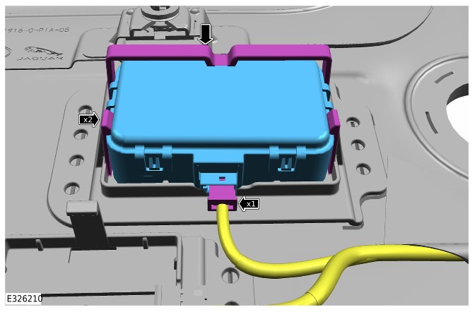
Installation

    • Install the RF receiver.
    • Secure the 2 clips.
    • Connect the electrical connector.