Range Rover Sport / L494 2017 INTAKE AIR DISTRIBUTION AND FILTERING
303-12A: Intake Air Distribution and Filtering - TDV6 3.0L Diesel /TDV6 3.0L Diesel - Gen 1.5/TDV6 3.0L Diesel - Gen 2
INTAKE AIR DISTRIBUTION AND FILTERING - TDV6 3.0L DIESEL /TDV6 3.0L DIESEL - GEN 1.5/TDV6 3.0L DIESEL - GEN 2 (G1509519)
Torque Specification
| DESCRIPTION | NM | LB-FT | LB-IN |
|---|---|---|---|
| Air cleaner outlet pipe clip | 3.5 | - | 31 |
| *Charge air cooler torx bolt | 9 | 7 | - |
| Charge air cooler M6 | 5 | 4 | - |
| Charge air cooler nut | 9 | 7 | - |
| Charge air cooler inlet pipe clip | 5 | - | 44 |
| Charge air cooler outlet pipe clip | 5 | - | 44 |
* A new nut must be installed.
Description and OperationINTAKE AIR DISTRIBUTION AND FILTERING - TDV6 3.0L DIESEL /TDV6 3.0L DIESEL - GEN 1.5/TDV6 3.0L DIESEL - GEN 2 (G1868450)
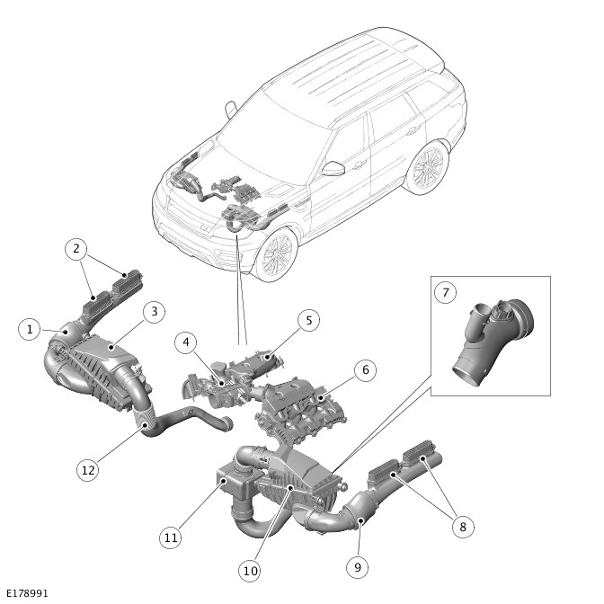
| ITEM | DESCRIPTION |
|---|---|
| 1 | Right dirty air duct (if fitted) |
| 2 | Right intake grilles (if fitted) |
| 3 | Right air cleaner (if fitted) |
| 4 | Electric throttle |
| 5 | Right intake manifold (integral with camshaft cover) |
| 6 | Left intake manifold (integral with camshaft cover) |
| 7 | EGR pipe (if fitted) |
| 8 | Left intake grilles |
| 9 | Left dirty air duct |
| 10 | Left air cleaner |
| 11 | Left clean air ducts with resonator |
| 12 | Right clean air ducts |

| ITEM | DESCRIPTION |
|---|---|
| 1 | Charge air duct – charge air intake valve to left clean air duct |
| 2 | Charge air ducts – secondary turbocharger to charge air intake valve |
| 3 | Charge air ducts – charge air cooler to electric throttle |
| 4 | Secondary turbocharger |
| 5 | Primary turbocharger |
| 6 | Charge air ducts – primary turbocharger to charge air cooler |
| 7 | Charge air cooler |
| 8 | Charge air ducts – charge air intake valve to charger air cooler |
| 9 | Charge air intake valve |

| ITEM | DESCRIPTION |
|---|---|
| 1 | Charge air ducts – charge air cooler to electric throttle |
| 2 | Turbocharger |
| 3 | Charge air cooler |
| 4 | Charge air ducts – turbocharger to charge air cooler |
The intake air distribution and filtering system cleans, compresses and cools the intake air. The system comprises according to bi- or mono-turbo variant is equipped:
| Bi-turbo engines | Mono-turbo engines |
| Two dirty air ducts. | A dirty air duct. |
| Two air cleaners. | An air cleaner. |
| Two clean air ducts, one with resonator. | A clean air duct with resonator. |
| Two turbochargers. | A turbocharger. |
| Charge air ducts. | A charge air duct. |
| A charge air intake valve. | - |
| A water cooled charge air cooler. | A water cooled charge air cooler. |
| An electric throttle. | An electric throttle. |
| Two intake manifolds. | Two intake manifolds. |
| A low pressure EGR duct | A low pressure EGR duct |
Air flows through the dirty air ducts, air cleaners and clean air ducts to the compressor intakes of the turbochargers. The turbochargers compress the air, which is then transferred through the charge air ducts to the charge air intake valve, charge air cooler, electric throttle and the intake manifolds.
DIRTY AIR DUCTS

| ITEM | DESCRIPTION |
|---|---|
| 1 | Front fender support |
| 2 | Screw |
| 3 | Intake grille |
| 4 | Screw |
| 5 | Intake grille |
| 6 | Front upper bracket |
| 7 | Front lower bracket |
| 8 | Non-porous sleeve |
The dirty air ducts are installed in the front fenders to transfer ambient air from under the edges of the hood to the air cleaners. If mono-turbo variant is equipped one air duct is fitted on the left side.
Each dirty air duct locates in the intake of the related air cleaner and is attached to the front inner fender with two brackets. The intake of each dirty air duct is attached to two intake grilles on top of the front fender support. When the hood is closed, the intake grilles locate in guides attached to the hood inner panel.
A porous section, covered by a non-porous sleeve to prevent moisture ingress, is incorporated into each dirty air duct to reduce induction noise.
AIR CLEANERS

| ITEM | DESCRIPTION |
|---|---|
| 1 | Screw (6 off) |
| 2 | Lid |
| 3 | Isolators |
| 4 | Air intake |
| 5 | Drain valve |
| 6 | Isolator |
| 7 | Base |
| 8 | Engine vacuum system connection (left air cleaner only) |
| 9 | Air outlet |
| 10 | Mass Air Flow (MAF) sensor (left air cleaner) or Mass Air Flow and Temperature (MAFT) sensor (right air cleaner) |
An air cleaner is located in each front corner of the engine compartment if bi-turbo variant is equipped and one air cleaner is located in the left front corner of the engine compartment if mono-turbo variant is equipped. Three spigots fitted with isolator bushes locate each air cleaner in holes in the related front inner fender and front suspension housing.
Each air cleaner consists of a filter element installed in a base and enclosed with a lid secured by six screws. The filter element is a pleated, paper type with an integral seal. Air intake and outlet connections are incorporated into the base and lid respectively. The bottom of the base incorporates a drain valve to prevent the accumulation of water in the air cleaner.
The lid of the left air cleaner incorporates a connection for the engine vacuum system. For additional information, refer to:
The air outlet connection of each air cleaner incorporates either a mass air flow (MAF) sensor (right air cleaner, if equipped) and a mass air flow and temperature (MAFT) sensor (left air cleaner). If mono-tubro variant if equipped only a MAFT sensors is fitted. The sensors are connected to the Engine Control module (ECM). For additional information, refer to:Electronic Engine Controls (303-14A Electronic Engine Controls - TDV6 3.0L Diesel /TDV6 3.0L Diesel - Gen 1.5/TDV6 3.0L Diesel - Gen 2, Description and Operation).
CLEAN AIR DUCTS

| ITEM | DESCRIPTION |
|---|---|
| 1 | Air intake - twin-turbo variant only |
| 2 | Convolute - twin-turbo variant only |
| 3 | Bracket - twin-turbo variant only |
| 4 | Air outlet - twin-turbo variant only |
| 5 | Air intake |
| 6 | Convolute |
| 7 | Resonator |
| 8 | Air outlet |
| 9 | Bracket |
| 10 | Charge air bypass hose connection |
The clean air ducts transfer air from the air cleaner outlets to the compressor intakes on the turbochargers. Each clean air duct incorporates a convolute section to accommodate relative movement between the engine mounted turbochargers and the body mounted air cleaners. The left clean air duct also incorporates a quarter wave resonator to reduce air induction noise.
If bi-turbo variant is fitted the left clean air duct also incorporates connection for the bypass hose from the charge air intake valve.For additional information, refer to:Turbocharger (303-04B Fuel Charging and Controls - Turbocharger - TDV6 3.0L Diesel, Description and Operation).
Brackets on the clean air ducts attach the ducts to the A/C compressor (left air duct) and the generator mounting bracket (right clean air duct, if equipped).
TURBOCHARGERS
The turbochargers are attached to the exhaust manifolds. A VGT (variable geometry turbine) turbocharger, designated as the primary turbocharger, is located on the left side of the engine. A fixed vane turbocharger, designated as the secondary turbocharger, is installed on the right side of the engine.For additional information, refer to:Turbocharger (303-04B Fuel Charging and Controls - Turbocharger - TDV6 3.0L Diesel, Description and Operation).
CHARGE AIR DUCTS

| ITEM | DESCRIPTION |
|---|---|
| 1 | Secondary turbocharger air tube connection |
| 2 | Charge air temperature sensor |
| 3 | Secondary turbocharger charge air pressure connection |

| ITEM | DESCRIPTION |
|---|---|
| 1 | Secondary turbocharger air tube connection |
| 2 | Charge air temperature sensor |
The charge air ducts interconnect the turbocharger compressor outlets, charge air intake valve (if bi-turbo variant is equipped), charge air cooler and electric throttle.
The charge air duct connection with the electric throttle incorporates connections for:
- An air tube connected to the secondary turbocharger. For additional information, refer to:Turbocharger (303-04B Fuel Charging and Controls - Turbocharger - TDV6 3.0L Diesel, Description and Operation).
- A charge air temperature sensor connected to the ECM.For additional information, refer to:Electronic Engine Controls (303-14A Electronic Engine Controls - TDV6 3.0L Diesel /TDV6 3.0L Diesel - Gen 1.5/TDV6 3.0L Diesel - Gen 2, Description and Operation).
The charge air duct connected to the outlet of the secondary turbocharger incorporates a connection for the charge air pressure sensor.For additional information, refer to:Electronic Engine Controls (303-14A Electronic Engine Controls - TDV6 3.0L Diesel /TDV6 3.0L Diesel - Gen 1.5/TDV6 3.0L Diesel - Gen 2, Description and Operation).
CHARGE AIR INTAKE VALVE - ONLY FOR BI-TURBO VARIANT
The charge air intake valve is attached to a bracket on the front subframe and the cooling pack protector.
The charge air intake valve is used by the ECM to change turbocharger operation between mono and bi-turbo modes. The valve controls the flow of air from the compressor of the secondary turbocharger to the clean air duct of the primary turbocharger and to the charge air cooler.For additional information, refer to:Turbocharger (303-04B Fuel Charging and Controls - Turbocharger - TDV6 3.0L Diesel, Description and Operation).
CHARGE AIR COOLERS

| ITEM | DESCRIPTION |
|---|---|
| 1 | Isolator bush |
| 2 | Air intake |
| 3 | Isolator bush |
| 4 | Front air duct |
| 5 | Rear air duct |
| 6 | Charge air cooler |
| 7 | Cooling water connection |
| 8 | Isolator |
| 9 | Air outlet |
| 10 | Isolator |
| 11 | Cooling water connection |
The charge air cooler is a water cooled charge air cooler that reduce the intake air temperature.
A charge air cooler is installed on the left side of the cooling pack, behind the left outer air intake in the front bumper. The charge air cooler is installed in air duct attached to the front bumper armature and the front end carrier. The lower end tank of the charge air cooler is located in the air ducts by two spigots fitted with isolator bushes. The upper end tank of each charge air cooler is attached to the front end carrier and the air ducts with two isolator bushes, nuts and bolts.
ELECTRIC THROTTLE

| ITEM | DESCRIPTION |
|---|---|
| 1 | Air intake |
| 2 | Electric motor |
| 3 | Right Exhaust Gas Recirculation (EGR) pipe connection |
| 4 | Right intake manifold connection |
| 5 | Manifold Absolute Pressure (MAP) sensor |
| 6 | Left intake manifold connection |
| 7 | Left EGR pipe connection |
The electric throttle regulates the air flow from the charge air coolers to the intake manifolds.
The electric throttle is installed at the front of the engine, between the cylinder heads. Two outlets on the electric throttle locate in the two intake manifolds. A stud bolt attaches the electric throttle to the right cylinder head.
The throttle plate is operated by a DC (Direct Current) electric motor attached to the throttle body. The motor is controlled by the ECM and is constantly adjusted the throttle according to the EGR valve opening, and in response to driver inputs with the throttle pedal, to control the amount of air allowed into the intake manifolds.For additional information, refer to:Electronic Engine Controls (303-14A Electronic Engine Controls - TDV6 3.0L Diesel /TDV6 3.0L Diesel - Gen 1.5/TDV6 3.0L Diesel - Gen 2, Description and Operation).
Pipe connections on both sides of the throttle body allow for the attachment of the outlet pipes from the Exhaust Gas Recirculation (EGR) valves. The pipe attachments in the throttle body are specifically designed to mix the recirculated exhaust gas with the intake air and provide an even distribution to each side of the engine.
A manifold absolute pressure (MAP) sensor is located in the top of the throttle body where the air flow splits for the two intake manifolds.For additional information, refer to:Electronic Engine Controls (303-14A Electronic Engine Controls - TDV6 3.0L Diesel /TDV6 3.0L Diesel - Gen 1.5/TDV6 3.0L Diesel - Gen 2, Description and Operation).
INTAKE MANIFOLDS
The intake manifolds are an integral part of the camshaft covers. Each intake manifold is connected to the electric throttle by a push fit, sealed connection.For additional information, refer to:Engine (303-01A Engine - TDV6 3.0L Diesel /TDV6 3.0L Diesel - Gen 1.5/TDV6 3.0L Diesel - Gen 2, Description and Operation).
Diagnosis and TestingINTAKE AIR DISTRIBUTION AND FILTERING - TDV6 3.0L DIESEL /TDV6 3.0L DIESEL - GEN 1.5/TDV6 3.0L DIESEL - GEN 2 (G2718601)
For a detailed description of the intake air distribution and filtering system and operation, refer to the relevant Description and Operation section of the workshop manual. REFER to:Intake Air Distribution and Filtering (303-12A Intake Air Distribution and Filtering - TDV6 3.0L Diesel /TDV6 3.0L Diesel - Gen 1.5/TDV6 3.0L Diesel - Gen 2, Description and Operation).
Diagnosis by substitution from a donor vehicle is NOT acceptable. Substitution of control modules does not guarantee confirmation of a fault and may also cause additional faults in the vehicle being checked and/or the donor vehicle.
Check and rectify basic faults before beginning diagnostic routines involving pinpoint tests.
- Verify the customer concern.
- Visually inspect for obvious signs of mechanical or electrical damage.
Visual Inspection
| MECHANICAL | ELECTRICAL |
|---|---|
|
|
- If an obvious cause for an observed or reported concern is found, correct the cause (if possible) before proceeding to the next step.
- If the cause is not visually evident, verify the symptom and refer to the Symptom Chart, alternatively check for Diagnostic Trouble Code(s) (DTC)s and refer to the DTC Index.
| SYMPTOM | POSSIBLE CAUSES | ACTION |
|---|---|---|
| Vehicle does not start/hard starting |
|
|
| Poor performance |
|
|
| Excessive intake noise |
|
|
Affected Vehicle Range
| MODEL: | MODEL YEAR: | VEHICLE IDENTIFICATION NUMBER (VIN): | ASSEMBLY PLANT: | APPLICABILITY: |
|---|---|---|---|---|
| Range Rover (LG) | 2015-2018 | 202850-510666 | Solihull | TDV6 3.0L Diesel - Gen 2 |
| Discovery (LR) | 2017-2018 | 000001-075312 | Solihull | TDV6 3.0L Diesel |
| Range Rover Sport (LW) | 2016-2018 | 100003-199996 | Solihull | TDV6 3.0L Diesel - Gen 2 |
| Range Rover Sport (LW) | 2015-2016 | 512861-599999 | Solihull | TDV6 3.0L Diesel - Gen 2 |
| Range Rover Sport (LW) | 2018 | 400291-413163 | Solihull | TDV6 3.0L Diesel - Gen 2 |
| Range Rover Sport (LW) | 2015-2018 | 600440-699492 | Solihull | TDV6 3.0L Diesel - Gen 2 |
| Range Rover Sport (LW) | 2018 | 800000-808712 | Solihull | TDV6 3.0L Diesel - Gen 2 |
A customer may express a concern of restricted performance accompanied by an illuminated Malfunction Indicator Lamp on the Instrument Cluster (IC), with DTC P0299-77 stored in the Powertrain Control Module (PCM).
Charge air cooler hose collapsing internally.
Should a customer express this concern, follow the service instruction below.
| DESCRIPTION | QUANTITY |
|---|---|
| Charge air cooler hose | 1 |
2017 Onwards Model Year (MY) vehicles
This procedure requires a minimum of Pathfinder 190 loaded or later.
-
The Jaguar Land Rover (JLR) approved diagnostic equipment will read the VIN for the vehicle and automatically take the vehicle out of ‘Transportation mode’ if required.
-
DTC P0299-77 can be set for multiple reasons, work through all required checks against this DTC before determining the charge air cooler hose requires renewal.
- Connect the JLR approved battery support unit.
- Connect the JLR approved diagnostic equipment to the vehicle and begin a new session.
- Follow the JLR approved diagnostic equipment prompts.
- Select 'ECU Diagnostics'.
- Select 'All DTCs'.
- If DTC P0299-77 is present, continue to the service instruction.
- If DTC P0299-77 is not present, do not continue with this bulletin and continue diagnosis using TOPIx Worksop Manual section 100-00: General Information - Diagnostic Trouble Code Index.
- Select 'Clear all DTCs'.
- Follow all on-screen instructions to complete this task.
- When all of the tasks are complete, exit the current session.
- Disconnect the JLR approved diagnostic equipment and the JLR approved battery support unit.
-
This procedure contains some variation in the illustrations depending on the vehicle specification, but the essential information is always correct.
-
This procedure contains illustrations showing certain components removed to provide extra clarity.
-
DTC P0299-77 can be set for multiple reasons, work through all required checks against this DTC before determining the charge air cooler hose requires renewal.
- Check the vehicle for an excessive engine oil level.
- If an excessive engine oil level is discovered, rectify the oil level using TOPIx repair procedures, recheck the vehicle and submit a separate warranty claim.
- If the oil level is ok, go to the next step.
- Check for excessive oil within the air induction system.
- If excessive levels of oil are discovered within the induction system, investigate and rectify using TOPIx repair procedures, recheck the vehicle and submit a separate warranty claim.
- If no excessive oil is detected, go to the next step.
- Check the vehicles exhaust system for leakage.
- If an exhaust system leak is discovered, please correct the leak using TOPIx repair procedures, recheck the vehicle and submit a separate warranty claim.
- If no exhaust leak is discovered, go to the next step.
- Check the charge air pressure sensor for signs of blockage.
- If the charge air sensor is found to be blocked, rectify the blocked sensor using TOPIx repair procedures, recheck the vehicle and submit a separate warranty claim.
- If the charge pressure sensor is ok, go to the next step.
- Check the turbocharger system/vanes mechanical integrity.
- If the turbocharger appears to be faulty, investigate and rectify using TOPIx repair procedures, recheck the vehicle and submit a separate warranty claim.
- If the turbocharger is ok, go to the next step.
- Complete a leakage test on the vehicles induction system, (see TOPIx Workshop Manual - 303-00: Engine System - General Information - General Procedures - Leakage Test Using Smoke Test Equipment).
- If a leak has been detected do not continue with this technical bulletin, please correct the leak using TOPIx repair procedures, retest the vehicle and submit a separate warranty claim.
- If no leak has been detected, go to step 7.
- Replace the charge air cooler hose, refer to steps 8 - 13.
- Remove the engine cover (See TOPIx workshop manual section: 501-05 Interior Trim and Ornamentation - Removal and Installation - Engine Cover - TDV6 3.0L Diesel - Gen 2/TDV6 3.0L Diesel /TDV6 3.0L Diesel - Gen 1.5).
- For Range Rover and Range Rover Sport vehicles, go to step 9.
- For Discovery vehicles, go to step 10.
- Remove the engine compartment front trim covers.
- Remove fasteners and lift both outer covers upwards.
- Pull the center trim upwards for removal.
Some components are removed for clarity.
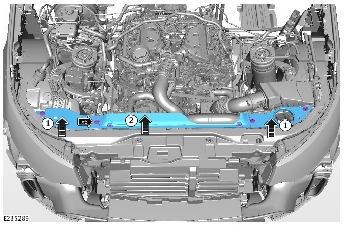
- Remove the engine compartment front trim covers.
- Remove fasteners and lift both outer covers upwards.
- Remove fasteners and lift the center cover upwards.
Some components are removed for clarity.
- Disconnect the vacuum pipe and the electrical connector from the charge air cooler hose, release the securing clip and disconnect the charge air cooler hose from the electronic throttle body, disconnect the charge air cooler hose from the top of the charge air cooler.
Some components are removed for clarity.

- Renew the charge air cooler hose.
- Repeat steps 11 - 8 in reverse to complete the operation.
For a list of DTCs that could be set on this vehicle, please refer to Section 100-00. REFER to:Diagnostic Trouble Code Index - TDV6 3.0L Diesel /TDV6 3.0L Diesel - Gen 1.5/TDV6 3.0L Diesel - Gen 2, DTC: Powertrain Control Module B10A2-07 to P02D7-32 (100-00 General Information, Description and Operation).
General ProceduresINTAKE AIR DISTRIBUTION AND FILTERING - TDV6 3.0L DIESEL /TDV6 3.0L DIESEL - GEN 1.5/TDV6 3.0L DIESEL - GEN 2
LEAKAGE TEST USING SMOKE TEST EQUIPMENT (G2374824)
- 01.01.28
- LEAKAGE TEST USING SMOKE TEST EQUIPMENT
- 3000 CC, TDV6
- 0.40
- USED WITHINS
SPECIAL TOOL(S)

JLR-303-1704-1
Blanking Plug for (Diesel) Air Intake Systems
GENERAL EQUIPMENT
| EQUIPMENT NAME |
|---|
| Adapter - High Pressure Diagnostic Leak Detector |
| High Pressure Diagnostic Leak Detector |
- Do not exceed 0.35 bar (5 psi, 34.5 kPA) test pressure, when testing the engine intake system.
- Only use calibrated equipment recommended by Jaguar Land Rover.
- This procedure contains some variation in the illustrations depending on the vehicle specification, but the essential information is always correct.
- This procedure contains illustrations showing certain components removed to provide extra clarity.
- Remove the engine cover.
Refer to:Engine Cover - TDV6 3.0L Diesel /TDV6 3.0L Diesel - Gen 1.5/TDV6 3.0L Diesel - Gen 2 (501-05 Interior Trim and Ornamentation, Removal and Installation).

-
NOTE:
Make sure the adapter is a good fit to the clean air duct. This must be an air tight seal.
Insert the appropriate adaptor into the clean air duct.General Equipment: Adapter - High Pressure Diagnostic Leak DetectorTorque: 3.5Nm


-
-
Insert the appropriate adaptor into the air filter outlet pipe.NOTE:
Make sure the adapter is a good fit to the clean air duct. This must be an air tight seal.
General Equipment: Adapter - High Pressure Diagnostic Leak Detector
- Tighten the hose clamp.
Torque: 3.5Nm
-


-
Install the special tool into the breather hose.Install the Special Tool(s): JLR-303-1704-1

-
CAUTION:
Never use dye/UV dye in intake or exhaust systems because it may coat or harm critical sensors.
NOTES:-
Only use Jaguar Land rover (JLR) approved vapor producing fluid.
-
60 ml maximum to refill the vapor producing fluid when the reservoir is empty.
- Check the high pressure diagnostic leak detector vapor producing fluid level. Top up if required.
-
-
CAUTION:
Never use dye/UV dye in intake or exhaust systems. Failure to follow this instruction may coat or harm critical sensors.
Check the high pressure diagnostic leak detector vapor producing fluid level. Top up if required.NOTES:-
Only use Jaguar Land rover (JLR) approved vapor producing fluid.
-
60 ml maximum to refill the vapor producing fluid when the reservoir is empty.
-
-
Connect the high pressure diagnostic leak detector to a suitable power supply.CAUTIONS:
-
Do not connect the high pressure diagnostic leak detector to a battery charger, battery support unit or jumper box.
-
Never connect the high pressure diagnostic leak detector to the vehicle with the engine running.
-
- Connect the high pressure diagnostic leak detector to a suitable air supply.


-
- Connect the high pressure diagnostic leak detector outlet pipe to the adaptor.
General Equipment: High Pressure Diagnostic Leak Detector
- Connect the high pressure diagnostic leak detector outlet pipe to the adaptor.


-
- Use the inspection light supplied with the high pressure diagnostic leak detector, to inspect for leaks.
- If a leak is detected, rectify the cause.
-
- Disconnect the high pressure diagnostic leak detector from the power supply.
- Disconnect the high pressure diagnostic leak detector from the air supply.
- Disconnect the high pressure diagnostic leak detector from the adaptor.
- Remove the special tool from the breather hose.
Remove the Special Tool(s): JLR-303-1704-1
- Install the breather hose.
- Remove the adaptor from the left air filter outlet pipe.
-
- Install the left air filter outlet pipe.
- Tighten the hose clamp.
Torque: 3.5Nm
- Remove the block off adaptor.
- Remove the adaptor from the right air filter outlet pipe.
-
- Install the right air filter outlet pipe.
- Tighten the hose clamp.
Torque: 3.5Nm
- Install the engine cover.
Refer to:Engine Cover - TDV6 3.0L Diesel /TDV6 3.0L Diesel - Gen 1.5/TDV6 3.0L Diesel - Gen 2 (501-05 Interior Trim and Ornamentation, Removal and Installation).
INTAKE AIR DISTRIBUTION AND FILTERING - TDV6 3.0L DIESEL /TDV6 3.0L DIESEL - GEN 1.5/TDV6 3.0L DIESEL - GEN 2
AIR CLEANER ELEMENT (G1509521)
- 19.10.10
- AIR FILTER ELEMENT - RENEW
- 3000 CC, TDV6
- 0.10
- USED WITHINS


- To install, reverse the removal procedure.
INTAKE AIR DISTRIBUTION AND FILTERING - TDV6 3.0L DIESEL /TDV6 3.0L DIESEL - GEN 1.5/TDV6 3.0L DIESEL - GEN 2
LEFT AIR CLEANER (G1519884)
- 19.10.03
- AIR CLEANER - LH - RENEW
- 3000 CC, TDV6
- 0.30
- USED WITHINS
Removal steps in this procedure may contain installation details.


- To install, reverse the removal procedure.
INTAKE AIR DISTRIBUTION AND FILTERING - TDV6 3.0L DIESEL /TDV6 3.0L DIESEL - GEN 1.5/TDV6 3.0L DIESEL - GEN 2
RIGHT AIR CLEANER (G1519885)
- 19.10.04
- AIR CLEANER - RH - RENEW
- 3000 CC, TDV6
- 0.30
- USED WITHINS
Removal steps in this procedure may contain installation details.

- Do not disassemble further if the component is removed for access only.
- To install, reverse the removal procedure.
INTAKE AIR DISTRIBUTION AND FILTERING - TDV6 3.0L DIESEL /TDV6 3.0L DIESEL - GEN 1.5/TDV6 3.0L DIESEL - GEN 2
LEFT CHARGE AIR COOLER - TDV6 3.0L DIESEL - GEN 2 (G1875612)
- 19.44.02
- INTERCOOLER - LH - RENEW
- 3000 CC, TDV6, GEN 2
- 1.70
- USED WITHINS
PART(S)
| STEP | PART NAME | QUANTITY |
|---|---|---|
| Removal Step 4 | Retaining clip | 1 |
| Removal Step 9 | Retaining clip | 1 |
-
Some variation in the illustrations may occur, but the essential information is always correct.
-
Removal steps in this procedure may contain installation details.
-
Refer to:Cooling System Draining and Vacuum Filling (303-03A Engine Cooling - TDV6 3.0L Diesel /TDV6 3.0L Diesel - Gen 1.5/TDV6 3.0L Diesel - Gen 2, General Procedures).
-
Refer to:Front Bumper Cover (501-19 Bumpers, Removal and Installation).


- To install, reverse the removal procedure.


