Range Rover Sport / L494 2017 MANUAL TRANSMISSION/TRANSAXLE, CLUTCH AND TRANSFER CASE USER MANUAL
308: Manual Transmission/Transaxle, Clutch and Transfer Case
308-07A: Four-Wheel Drive Systems
Specification
FOUR-WHEEL DRIVE SYSTEMS (G1509690)
Torque Specifications
* New bolts must be used when a new component is installed.
| DESCRIPTION | NM | LB-FT |
|---|---|---|
| * Transfer case shift motor bolts | 35 | 26 |
| * Transfer case clutch control solenoid bolts | 5 | 4 |
| * High/Low range position sensor bolts | 5 | 4 |
| Transmission undershield M10 bolts | 60 | 44 |
| Transmission undershield M6 bolts | 10 | 7 |
| Transmission support crossmember M12 bolts | 110 | 81 |
| Transmission support crossmember M8 bolt | 24 | 17 |
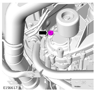
TRANSFER CASE CLUTCH SOLENOID (G1960606)
- 41.30.08
- SOLENOID - CLUTCH CONTROL - RENEW
- ALL DERIVATIVES
- 0.20
- USED WITHINS
PART(S)
| STEP | PART NAME | QUANTITY |
|---|---|---|
| Installation Step 1 | Transfer Case Clutch Solenoid kit | 1 |
-
Raise and support the vehicle.WARNING:
Make sure to support the vehicle with axle stands.
- Drain the transfer case.
Refer to:Transfer Case Draining and Filling (308-07C Transfer Case - [+] Twin Speed Transfer Case, General Procedures).
-
CAUTION:
Connect the diagnostic tool, prior to removal of the solenoid. Carry out the diagnostic service function transfer case – solenoid replacement.
NOTES:-
Some fluid spillage is inevitable during this operation.
-
Note the orientation of the electrical connector prior to removal.
-

-
CAUTIONS:
-
Failure to energize the solenoid to aid installation of the arm, may result in damage to the shift fork once the component is installed and the system is operated.
-
Make sure the seal is installed correctly.
-
Make sure that new bolts are installed.
-
Make sure that the electrical connector is installed in the correct orientation as noted in the removal step.
-
Make sure that the component sits flush to the transfer case.
Connect the electrical connector and energize the solenoid (use the service function transfer case – solenoid replacement to assist with energizing the solenoid) to allow the arm to extend and correctly locate into the shift fork.NOTE:Tighten the retaining bolts evenly and progressively.
Torque: 5Nm -
- Fill the transfer case.
Refer to:Transfer Case Draining and Filling (308-07C Transfer Case - [+] Twin Speed Transfer Case, General Procedures).
- Using the approved diagnostic equipment, clear all diagnostic trouble code(s) (DTCs) and check for correct operation.
FOUR-WHEEL DRIVE SYSTEMS
HIGH/LOW RANGE SENSOR (G2003291)
- 41.30.07
- SENSOR - POSITION - HI/LOW RATIO - RENEW
- ALL DERIVATIVES
- 0.30
- USED WITHINS
- Some variation in the illustrations may occur, but the essential information is always correct.
- Some components shown removed for clarity.
- Disconnect the battery ground cable.
Refer to:Specifications (414-00 Battery and Charging System - General Information, Specifications).
-
Raise and support the vehicle.WARNING:
Make sure to support the vehicle with axle stands.


-
Raise and support the vehicle.WARNING:
Make sure to support the vehicle with axle stands.
- Connect the battery ground cable.
Refer to:Specifications (414-00 Battery and Charging System - General Information, Specifications).
-
- Connect the Land Rover approved diagnostic equipment.
- Start the service function "transfer case-absolute position sensor replacement".
- Clear any Diagnostic Trouble Codes (DTCs) after calibration and check for correct operation.
FOUR-WHEEL DRIVE SYSTEMS
TRANSFER CASE CONTROL MODULE (G2469183)
-
This procedure contains some variation in the illustrations depending on the vehicle specification, but the essential information is always correct.
-
This procedure contains illustrations showing certain components removed to provide extra clarity.
- Disconnect the startup battery ground cable.
Refer to:Specifications (414-00 Battery and Charging System - General Information, Specifications).
- Raise and support the vehicle on a suitable 2 post lift.
Refer to:Lifting (100-02 Jacking and Lifting, Description and Operation).


-
- Install the TCCM.
- Install and tighten the 2 bolts.
Torque: 18Nm
- Connect the electrical connector.
-
NOTE:
If equipped.
- Install the heatshield.
- Install and tighten the 3 bolts.
Torque: 8Nm
- Connect the startup battery ground cable.
Refer to:Specifications (414-00 Battery and Charging System - General Information, Specifications).
-
- Connect the Jaguar Land Rover (JLR) approved diagnostic equipment.
- Start the diagnostic service function "transfer case-transfer case control module replacement".
- Clear any Diagnostic Trouble Code(s) (DTC) after calibration and check for correct operation.
308-07B: Transfer Case - [+] Single Speed Transfer Case
TRANSFER CASE - [+] SINGLE SPEED TRANSFER CASE (G1606372)
Sealants and Lubricants
| ITEM | SPECIFICATION |
|---|---|
| * Recommended oil | Castrol BOT850 |
| Capacity - Wet and dry fill | 0.75 litres, (1.3 pints) (0.8 US quarts) |
| Input shaft splines grease | Weicon TL7391 |
| Transfer case sealant | TL 7990 Hylomar black 102 or equivalent |
* Do not use any lubricant other than that specified
| ITEM | SPECIFICATION |
|---|---|
| Model | ITC Torsen |
| Type | Single speed, permanent four wheel drive transfer box with 42 front / 58 rear (± 20% to either axle, dependant on traction ) torque split across the centre differential |
| Ratio | 1:1 |
Torque Specifications
| DESCRIPTION | NM | LB-FT |
|---|---|---|
| Transfer case fluid drain plug | 28 | 21 |
| Transfer case fluid filler/level plug | 28 | 21 |
| Transmission support insulator to transfer case bolts | 60 | 44 |
| Transfer case to transmission bolts | 45 | 33 |
| Transfer case bolts | 35 | 26 |
| Wiring bracket bolts | 25 | 18 |
| Earth strap bolt | 25 | 18 |
| * Front driveshaft to transfer case output flange: | ||
| Stage 1 | 45 | 33 |
| Stage 2 | Further 90° | Further 90° |
* New 'patched' Torx bolts must be installed
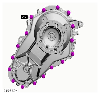
Description and OperationTRANSFER CASE - [+] SINGLE SPEED TRANSFER CASE (G1607038)
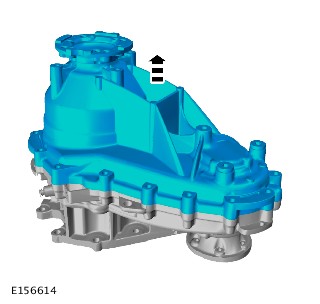
COMPONENT LOCATION

| ITEM | DESCRIPTION |
|---|---|
| 1 | Single speed transfer case |
The new Single speed Transfer Case is standard fitted for V6 Petrol and V6 Diesel engines. (Twin speed Transfer Case is optional.)
The Single speed transfer case is full time, permanent four-wheel-drive unit, with 40/60 torque distribution to the front and rear driveshafts.
Common components with Twin-speed Transfer Case:
- Front and Rear Flanges
- Main Seals
- Main Bearings
- Fill/Drain Plugs
- Fixings and Torques
- Breather
- Tachograph encoder (optional)
The improvements of the new Single speed Transfer Case are the following:
- Different oil specification - Castrol BOT850 with friction modifier
- Reduced Complexity
- No electronic controls
- Optimized dynamic vehicle behavior
The Single speed TC consists of 25 components, the weight and inertia were reduced for improved economy.
A unique type of grease, Weicon anti-seize montagepaste grau TL 7391, must be applied to the transfer case input shaft spline when installing the transfer case.

| ITEM | DESCRIPTION |
|---|---|
| 1 | Input shaft spline |
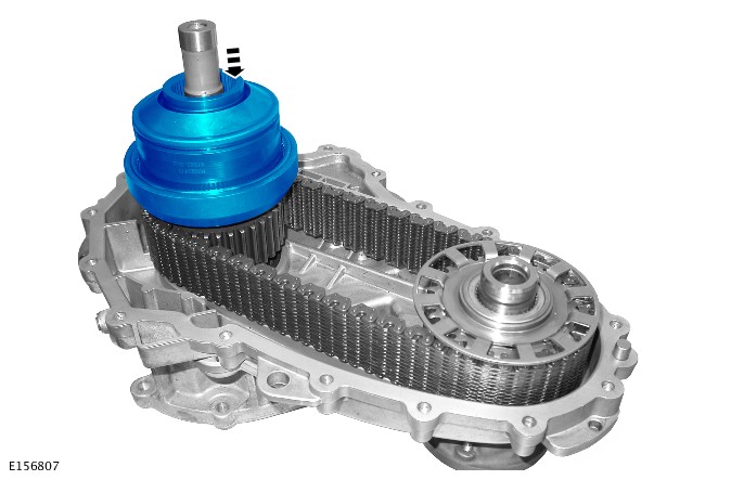
The torque input from the transmission is passed to the transfer case input shaft. The input shaft connected directly to the differential coupling. The differential coupling connects to the housing which splits the torque between the internal gear and the sun gear by the six planetary gears. The internal gear is connected and passes the torque to the rear output flange. The sun gear is connected to the chain drive sprocket and passes the torque to the front output flange via the chain.
The center differential responds to the torque changes at the axles. The basic torque distribution between the front and rear axles is 40/60% at normal drive conditions. If an axle loses traction, the driving torque is redirected instantaneously to the other axle between 65/35% Front/Rear and 20/80% Front/Rear.

| ITEM | DESCRIPTION |
|---|---|
| 1 | Input shaft |
| 2 | Drive chain sprocket |
| 3 | Center differential cap |
| 4 | Friction washer |
| 5 | Planetary gear (6 off) |
| 6 | Center differential internal gear |
| 7 | Rear output flange |
| 8 | Center differential coupling |
| 9 | Center differential sun gear |
| 10 | Rear housing assembly |
| 11 | Drive chain |
| 12 | Drive chain sprocket - Front output |
| 13 | Front output flange |
| 14 | Front housing assembly |

Input torque from the transmission is transferred to the input shaft of the transfer case and then onto the differential coupling. The coupling is connected to the differential housing. The planetary gears are held in place by the differential housing, which are connected to the differential internal gear, and the sun gear. The torque is then distributed to both the differential internal gear, and the sun gear, which are connected to the outputs of the transfer case. The internal gear is connected directly to the rear output flange, the sun gear is connected directly to the drive chain sprocket and therefore to the chain drive, which provides front output flange rotation.
Front Casing Assembly
The front casing assembly provides the location for the input shaft bearing and the front output flange bearing. It is also equipped with threaded holes to mount the chassis mounting bush, 2 lifting eyes and a breather cartridge for the transfer case breather pipe. The breather pipe allows equalization between atmospheric and internal transfer case pressure.
The front casing has an additional boss cast on the inside. The boss is used to mount two snubbers - one on drive side of the chain and one on the coast side - which are secured with 2 screws. The snubbers are suppressing chain vibrations which can occur under medium acceleration conditions, therefore improving NVH (Noise, Vibration and Harshness) issues. During normal operation the chain does not contact the snubbers.
Rear Casing Assembly
The rear casing assembly provides the location for the rear output flange bearing, the oil fill and drain plug. Fins are cast into the rear casing assembly to improve heat dissipation. The part number & serial number are printed on a bar code label.
Chain Drive
The chain-drive transfers drive from the center differential to the front output flange. A 3/8" pitch chain connects the sprocket on the transfer case input shaft with the sprocket on the front output flange. As both sprockets have the same number of teeth, the rotational speed of both sprockets is identical. During the vehicle operation the chain delivers the oil upwards and provides the lubrication for the input shaft, the output flange bearings, and the center differential assembly.
When installing or replacing the chain, the BLUE guide links must be facing the center differential, towards the rear output flange.
Center differential

| ITEM | DESCRIPTION |
|---|---|
| 1 | Drive chain |
| 2 | Center differential cover |
| 3 | Fixing nut |
| 4 | Planetary gear (6 off) |
| 5 | Center differential internal gear |
| 6 | Center differential housing |
| 7 | Coupling |
| 8 | Rear output shaft |
| 9 | Center differential sun gear |
| 10 | Drive chain sprocket |
| 11 | Friction washer |
| 12 | Input shaft |
The center differential assembly is the primary feature of the transfer case. Torque is transmitted through the center differential coupling and housing, and distributed by the planetary gear set to the differential gears and the front and rear output flanges.
The assembly comprises 6 planetary gears, which are equally spaced within the center differential housing. The planetary gears are supported in both directions by the differential casing and the differential cap.
The different basic torque distribution results from the different circle diameters of the internal gear and the sun gear. If an axle loses traction, the bias between the casing, the planetary gears and the cap generates internal friction inside the differential, and the torque directed to the other axle.
Diagnosis and TestingTRANSFER CASE - [+] SINGLE SPEED TRANSFER CASE (G2001812)
For a detailed description of the Transfer Case - Single speed, refer to the relevant Description and Operation section in the workshop manual. REFER to:Transfer Case (308-07B Transfer Case - [+] Single Speed Transfer Case, Description and Operation).
Diagnosis by substitution from a donor vehicle is NOT acceptable. Substitution of control modules does not guarantee confirmation of a fault, and may also cause additional faults in the vehicle being tested and/or the donor vehicle.
-
If the control module or a component is suspect and the vehicle remains under manufacturer warranty, refer to the Warranty Policy and Procedures manual, or determine if any prior approval programme is in operation, prior to the installation of a new module/component.
-
When performing voltage or resistance tests, always use a digital multimeter accurate to three decimal places, and with an up-to-date calibration certificate. When testing resistance always take the resistance of the digital multimeter leads into account.
-
Check and rectify basic faults before beginning diagnostic routines involving pinpoint tests.
- Verify the customer concern
- Visually inspect for obvious signs of damage and system integrity
Visual Inspection
| MECHANICAL |
|---|
|
- If an obvious cause for an observed or reported concern is found, correct the cause (if possible) before proceeding to the next step
- If the cause is not visually evident, verify the symptom and refer to the Symptom Chart, alternatively check for Diagnostic Trouble Codes (DTCs) and refer to the DTC Index
- Check JLR claims submission system for open campaigns. Refer to the corresponding bulletins and SSMs which may be valid for the specific customer complaint and carry out the recommendations as required.
| SYMPTOM | POSSIBLE CAUSES | ACTION |
|---|---|---|
| Warning message/gearbox fault displayed on instrument cluster |
|
|
| Whining noise |
|
|
At full lock, there will be some tyre scrubbing; as the temperature drops, scrubbing may be experienced as stick/slip judder. This is normal and does not require any service intervention
Vibration from the transfer case may be caused by the installation of incorrect front/rear drive units. Refer to Sections 205-02 and 205-03 for further guidance on how to diagnose and rectify this issue
TRANSFER CASE - [+] SINGLE SPEED TRANSFER CASE
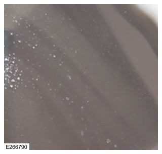
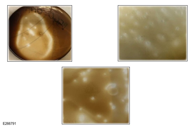
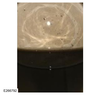
TRANSFER CASE OIL COLOR CHARTS (G2723410)
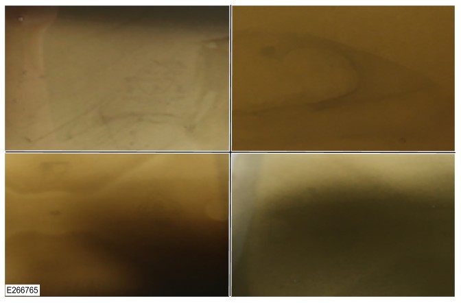
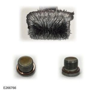
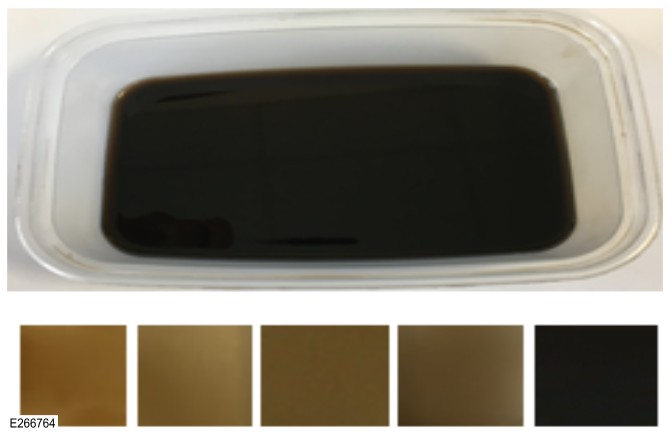
Oil Condition Not Acceptable - NOK


General Procedures
TRANSFER CASE - [+] SINGLE SPEED TRANSFER CASE
TRANSFER CASE DRAINING AND FILLING (G1606373)
- 41.20.04
- TRANSFER GEARBOX DRAIN AND REFILL
- SINGLE SPEED TRANSFER CASE
- 0.20
- USED WITHINS
- 41.20.04
- TRANSFER GEARBOX DRAIN AND REFILL
- TWIN SPEED TRANSFER CASE
- 0.20
- USED WITHINS
PART(S)
| STEP | PART NAME | QUANTITY |
|---|---|---|
| Draining Step 5 | Transfer case drain plug washer | 1 |
| Filling Step 3 | Transfer case fill plug washer | 1 |
Some variation in the illustrations may occur, but the essential information is always correct.
-
Raise and support the vehicle.WARNING:
Do not work on or under a vehicle supported only by a jack. Always support the vehicle on safety stands.
- Position a container to collect the fluid.

- Allow the fluid to drain.
- Refill transfer case with the recommended fluid, until the fluid is level with bottom of filler/level plug hole.
-
NOTES:
-
Make sure that all the component mating faces are clean.
-
Install a new sealing washer.
Torque: 28Nm -
TRANSFER CASE - [+] SINGLE SPEED TRANSFER CASE
TRANSFER CASE FRONT OUTPUT SEAL (G2003498)
SPECIAL TOOL(S)

205-818
Installer, Seal

308-620
Installer, Seal

308-636
Installer

JLR-308-926
Support Tool, Transfer Case

JLR-308-933
Remover, Transfer Case Flange
PART(S)
| STEP | PART NAME | QUANTITY |
|---|---|---|
| Installation Step 2 | Transfer case front output seal and bearing kit | 1 |
- Some variation in the illustrations may occur, but the essential information is always correct.
- Some components shown removed for clarity.
- Disconnect the battery ground cable.
Refer to:Specifications (414-00 Battery and Charging System - General Information, Specifications).
-
Raise and support the vehicle.WARNING:
Make sure to support the vehicle with axle stands.
- Drain the transfer case fluid.
Refer to:Transfer Case Draining and Filling (308-07C Transfer Case - [+] Twin Speed Transfer Case, General Procedures).
- Remove the transfer case.
Refer to:Transfer Case - TDV6 3.0L Diesel /TDV6 3.0L Diesel - Gen 1.5/TDV6 3.0L Diesel - Gen 2 (308-07B Transfer Case - [+] Single Speed Transfer Case, Removal).Refer to:Transfer Case - V6 S/C 3.0L Petrol (308-07B Transfer Case - [+] Single Speed Transfer Case, Removal).Refer to:Transfer Case - INGENIUM I4 2.0L Diesel (308-07B Transfer Case - [+] Single Speed Transfer Case, Removal).

-
Remove the sealant from the transfer case mating faces.CAUTION:
Make sure that the mating faces are clean and free of foreign material.


-
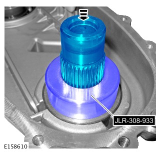
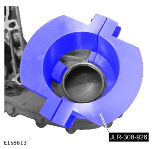
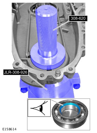
Install the special tool.Special Tool(s): JLR-308-926

-
CAUTION:
Make sure that the special tool is correctly located. This will make sure that the snap ring is fully compressed during the next step.
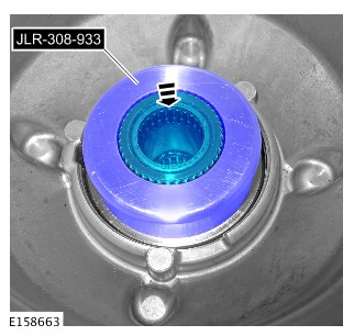
Release the snap ring using the special tool.Special Tool(s): JLR-308-933


-
Position the special tool as shown, to support the transfer case during the next step.Special Tool(s): JLR-308-926
-
CAUTION:
- The chamfer on the bearing inner track must face the seal.
- The transfer case must be supported by the special tool on a flat surface during this step.
- Install the bearing.
Special Tool(s): 308-620
-
- Install the seal.
Special Tool(s): 308-636
- Install the seal.

-
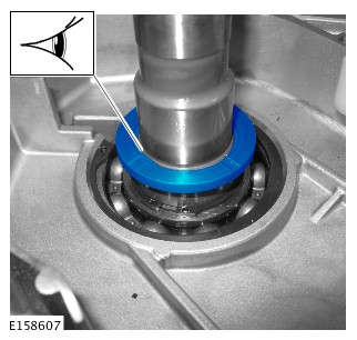
- Centralise the snap ring in the snap ring groove before installing the output flange.
- Extreme care is necessary to make sure the snap ring enters the bearing squarely.
- Install a new snap ring.
- Using the special tool and with assistance, install the drive flange.
Special Tool(s): 205-818

-
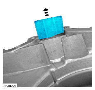
Apply a 2 mm bead of sealant to one surface of the transfer case mating face, as shown.Refer to:Specifications (308-07A Four-Wheel Drive Systems, Specifications).


- Install the transfer case.
Refer to:Transfer Case - TDV6 3.0L Diesel /TDV6 3.0L Diesel - Gen 1.5/TDV6 3.0L Diesel - Gen 2 (308-07B Transfer Case - [+] Single Speed Transfer Case, Installation).Refer to:Transfer Case - V6 S/C 3.0L Petrol (308-07B Transfer Case - [+] Single Speed Transfer Case, Installation).Refer to:Transfer Case - INGENIUM I4 2.0L Diesel (308-07B Transfer Case - [+] Single Speed Transfer Case, Installation).
- Fill the transfer case with the recommended fluid.
Refer to:Transfer Case Draining and Filling (308-07C Transfer Case - [+] Twin Speed Transfer Case, General Procedures).
- Connect the battery ground cable.
Refer to:Specifications (414-00 Battery and Charging System - General Information, Specifications).
TRANSFER CASE - [+] SINGLE SPEED TRANSFER CASE
TRANSFER CASE REAR OUTPUT SEAL (G2006820)
- 41.20.54
- OIL SEAL(S) - REAR OUTPUT SHAFT - RENEW
- 3000 CC, TDV6, DIESEL, SINGLE SPEED TRANSFER CASE, WITH PARTICULATE FILTER, WITH DIESEL EXHAUST
- 2.60
- USED WITHINS
- 41.20.54
- OIL SEAL(S) - REAR OUTPUT SHAFT - RENEW
- 3000 CC, TDV6, DIESEL, TWIN SPEED TRANSFER CASE, WITH PARTICULATE FILTER, WITH DIESEL EXHAUST FL
- 3.40
- USED WITHINS
SPECIAL TOOL(S)

204-525-1
Replacer, Drive Flange

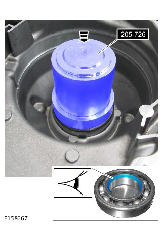
205-726
Remover/Installer, Wheel Hub Bearing
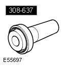
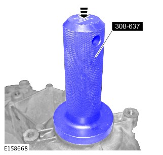
308-637
Installer
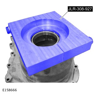
JLR-308-927
Support Tool, Transfer Case

JLR-308-931
Remover, Transfer Case Flange
JLR-308-933
Remover, Transfer Case Flange
PART(S)
| STEP | PART NAME | QUANTITY |
|---|---|---|
| Installation Step 2 | Transfer case rear output seal and bearing kit | 1 |
| Installation Step 4 | Transfer case rear output shaft snap ring | 1 |
Make sure that all parts provided with the install kit are installed.
- Some variation in the illustrations may occur, but the essential information is always correct.
- Some components shown removed for clarity.
- Disconnect the battery ground cable.
Refer to:Specifications (414-00 Battery and Charging System - General Information, Specifications).
-
Raise and support the vehicle.WARNING:
Make sure to support the vehicle with axle stands.
- Drain the transfer case fluid.
Refer to:Transfer Case Draining and Filling (308-07C Transfer Case - [+] Twin Speed Transfer Case, General Procedures).
- Remove the transfer case.
Refer to:Transfer Case - TDV6 3.0L Diesel /TDV6 3.0L Diesel - Gen 1.5/TDV6 3.0L Diesel - Gen 2 (308-07B Transfer Case - [+] Single Speed Transfer Case, Removal).Refer to:Transfer Case - V6 S/C 3.0L Petrol (308-07B Transfer Case - [+] Single Speed Transfer Case, Removal).Refer to:Transfer Case - INGENIUM I4 2.0L Diesel (308-07B Transfer Case - [+] Single Speed Transfer Case, Removal).
-
Remove the sealant from the transfer case mating faces.CAUTION:
Make sure that the mating faces are clean and free of foreign material.


-
Install the special tool.Special Tool(s): JLR-308-927

-
CAUTION:
Make sure that the special tool is correctly located. This will make sure that the snap ring is fully compressed during the next step.
Install the special tool.Special Tool(s): JLR-308-931

-
CAUTION:
- Do not use excessive force whilst removing the flange assembly.
- Discard the snap ring.
Release the transfer case rear output shaft.Special Tool(s): JLR-308-933


-
Position the special tool as shown, to support the transfer case during the next step.Special Tool(s): JLR-308-927
-
CAUTION:
The chamfer on the bearing inner track must face the seal.
- Install the bearing.
Special Tool(s): 205-726
- Install the bearing.
-
- Install the seal.
Special Tool(s): 308-637
- Install the seal.
-
- Centralize the snap ring in the snap ring groove before installing the output flange.
- Extreme care is necessary to make sure the snap ring enters the bearing squarely.
- Install a new snap ring.
- Using the special tool and with assistance, install the drive flange.
Special Tool(s): 204-525-1


-
Apply a 2 mm bead of sealant to one surface of the transfer case mating face, as shown.Refer to:Specifications (308-07A Four-Wheel Drive Systems, Specifications).
- Install the transfer case.
Refer to:Transfer Case - TDV6 3.0L Diesel /TDV6 3.0L Diesel - Gen 1.5/TDV6 3.0L Diesel - Gen 2 (308-07B Transfer Case - [+] Single Speed Transfer Case, Installation).Refer to:Transfer Case - V6 S/C 3.0L Petrol (308-07B Transfer Case - [+] Single Speed Transfer Case, Installation).Refer to:Transfer Case - INGENIUM I4 2.0L Diesel (308-07B Transfer Case - [+] Single Speed Transfer Case, Installation).
- Fill the transfer case with the recommended fluid.
Refer to:Transfer Case Draining and Filling (308-07C Transfer Case - [+] Twin Speed Transfer Case, General Procedures).
- Connect the battery ground cable.
Refer to:Specifications (414-00 Battery and Charging System - General Information, Specifications).
TRANSFER CASE - [+] SINGLE SPEED TRANSFER CASE
TRANSFER CASE REAR OUTPUT SHAFT BEARING (G1947975)
- 41.20.19
- BEARING - REAR OUTPUT SHAFT - RENEW
- 3000 CC, TDV6, DIESEL, SINGLE SPEED TRANSFER CASE, WITH PARTICULATE FILTER, WITH DIESEL EXHAUST
- 2.60
- USED WITHINS
- 41.20.19
- BEARING - REAR OUTPUT SHAFT - RENEW
- 3000 CC, TDV6, DIESEL, TWIN SPEED TRANSFER CASE, WITH PARTICULATE FILTER, WITH DIESEL EXHAUST FL
- 3.40
- USED WITHINS
SPECIAL TOOL(S)
204-525-1
Replacer, Drive Flange
205-726
Remover/Installer, Wheel Hub Bearing
308-637
Installer
JLR-308-927
Support Tool, Transfer Case
JLR-308-931
Remover, Transfer Case Flange
JLR-308-933
Remover, Transfer Case Flange
PART(S)
| STEP | PART NAME | QUANTITY |
|---|---|---|
| Installation Step 2 | Transfer case rear output shaft bearing | 1 |
| Installation Step 3 | Transfer case rear output shaft oil seal | 1 |
| Installation Step 4 | Transfer case rear output shaft snap ring | 1 |
- Some variation in the illustrations may occur, but the essential information is always correct.
- Some components shown removed for clarity.
- Disconnect the battery ground cable.
Refer to:Specifications (414-00 Battery and Charging System - General Information, Specifications).
-
Raise and support the vehicle.WARNING:
Make sure to support the vehicle with axle stands.
- Drain the transfer case fluid.
Refer to:Transfer Case Draining and Filling (308-07C Transfer Case - [+] Twin Speed Transfer Case, General Procedures).
- Remove the transfer case.
Refer to:Transfer Case - TDV6 3.0L Diesel /TDV6 3.0L Diesel - Gen 1.5/TDV6 3.0L Diesel - Gen 2 (308-07B Transfer Case - [+] Single Speed Transfer Case, Removal).Refer to:Transfer Case - V6 S/C 3.0L Petrol (308-07B Transfer Case - [+] Single Speed Transfer Case, Removal).Refer to:Transfer Case - INGENIUM I4 2.0L Diesel (308-07B Transfer Case - [+] Single Speed Transfer Case, Removal).
-
Remove the sealant from the transfer case mating faces.CAUTION:
Make sure that the mating faces are clean and free of foreign material.
-
Install the special tool.Special Tool(s): JLR-308-927
-
CAUTION:
Make sure that the special tool is correctly located. This will make sure that the snap ring is fully compressed during the next step.
Install the special tool.Special Tool(s): JLR-308-931
-
CAUTION:
- Do not use excessive force whilst removing the flange assembly.
- Discard the snap ring.
Release the transfer case rear output shaft.Special Tool(s): JLR-308-933
-
Position the special tool as shown, to support the transfer case during the next step.Special Tool(s): JLR-308-927
-
CAUTION:
The chamfer on the bearing inner track must face the seal.
- Install the bearing.
Special Tool(s): 205-726
- Install the bearing.
-
- Install the seal.
Special Tool(s): 308-637
- Install the seal.
-
- Centralize the snap ring in the snap ring groove before installing the output flange.
- Extreme care is necessary to make sure the snap ring enters the bearing squarely.
- Install a new snap ring.
- Using the special tool and with assistance, install the drive flange.
Special Tool(s): 204-525-1
-
Apply a 2 mm bead of sealant to one surface of the transfer case mating face, as shown.Refer to:Specifications (308-07A Four-Wheel Drive Systems, Specifications).
- Install the transfer case.
Refer to:Transfer Case - TDV6 3.0L Diesel /TDV6 3.0L Diesel - Gen 1.5/TDV6 3.0L Diesel - Gen 2 (308-07B Transfer Case - [+] Single Speed Transfer Case, Installation).Refer to:Transfer Case - V6 S/C 3.0L Petrol (308-07B Transfer Case - [+] Single Speed Transfer Case, Installation).Refer to:Transfer Case - INGENIUM I4 2.0L Diesel (308-07B Transfer Case - [+] Single Speed Transfer Case, Installation).
- Fill the transfer case with the recommended fluid.
Refer to:Transfer Case Draining and Filling (308-07C Transfer Case - [+] Twin Speed Transfer Case, General Procedures).
- Connect the battery ground cable.
Refer to:Specifications (414-00 Battery and Charging System - General Information, Specifications).
TRANSFER CASE - [+] SINGLE SPEED TRANSFER CASE
TRANSFER CASE DIFFERENTIAL (G1614710)
- Disconnect the battery ground cable.
Refer to:Specifications (414-00 Battery and Charging System - General Information, Specifications).
-
Raise and support the vehicle.WARNING:
Make sure to support the vehicle with axle stands.
-
Refer to:Transfer Case Draining and Filling (308-07B Transfer Case - [+] Single Speed Transfer Case, General Procedures).
-
Refer to:Transfer Case - TDV6 3.0L Diesel /TDV6 3.0L Diesel - Gen 1.5/TDV6 3.0L Diesel - Gen 2 (308-07B Transfer Case - [+] Single Speed Transfer Case, Removal).Refer to:Transfer Case - V6 S/C 3.0L Petrol (308-07B Transfer Case - [+] Single Speed Transfer Case, Removal).
-
Remove the sealant from the transfer case mating faces.CAUTION:
Make sure that the mating faces are clean and free of foreign material.
-
Refer to:Transfer Case - TDV6 3.0L Diesel /TDV6 3.0L Diesel - Gen 1.5/TDV6 3.0L Diesel - Gen 2 (308-07B Transfer Case - [+] Single Speed Transfer Case, Installation).Refer to:Transfer Case - V6 S/C 3.0L Petrol (308-07B Transfer Case - [+] Single Speed Transfer Case, Installation).
-
Refer to:Transfer Case Draining and Filling (308-07B Transfer Case - [+] Single Speed Transfer Case, General Procedures).
- Connect the battery ground cable.
Refer to:Specifications (414-00 Battery and Charging System - General Information, Specifications).
TRANSFER CASE - [+] SINGLE SPEED TRANSFER CASE
TRANSMISSION TO POWER TRANSFER UNIT CONNECTING SLEEVE SEAL (G2006821)
- 44.20.21
- OIL SEAL - OUTPUT SHAFT - RENEW
- 3000 CC, TDV6, DIESEL, SINGLE SPEED TRANSFER CASE, WITH PARTICULATE FILTER, WITH DIESEL EXHAUST
- 2.10
- USED WITHINS
- 44.20.21
- OIL SEAL - OUTPUT SHAFT - RENEW
- 3000 CC, TDV6, DIESEL, TWIN SPEED TRANSFER CASE, WITH PARTICULATE FILTER, WITH DIESEL EXHAUST FL
- 2.10
- USED WITHINS
SPECIAL TOOL(S)

100-012
Slide Hammer

307-520
Installer, Output Shaft Seal
JLR-308-930
Installer, Oil Seal

JLR-308-932
Remover, Oil Seal
PART(S)
| STEP | PART NAME | QUANTITY |
|---|---|---|
| Installation Step 1 | Transfer case input shaft oil seal | 1 |
- Some variation in the illustrations may occur, but the essential information is always correct.
- Some components shown removed for clarity.
- Disconnect the battery ground cable.
Refer to:Specifications (414-00 Battery and Charging System - General Information, Specifications).
-
Raise and support the vehicle.WARNING:
Make sure to support the vehicle with axle stands.
- Remove the transfer case.
Refer to:Transfer Case - TDV6 3.0L Diesel /TDV6 3.0L Diesel - Gen 1.5/TDV6 3.0L Diesel - Gen 2 (308-07B Transfer Case - [+] Single Speed Transfer Case, Removal).Refer to:Transfer Case - V6 S/C 3.0L Petrol (308-07B Transfer Case - [+] Single Speed Transfer Case, Removal).Refer to:Transfer Case - INGENIUM I4 2.0L Diesel (308-07B Transfer Case - [+] Single Speed Transfer Case, Removal).
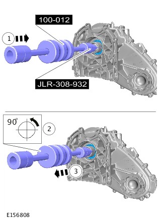

- Install the transfer case.
Refer to:Transfer Case - TDV6 3.0L Diesel /TDV6 3.0L Diesel - Gen 1.5/TDV6 3.0L Diesel - Gen 2 (308-07B Transfer Case - [+] Single Speed Transfer Case, Installation).Refer to:Transfer Case - V6 S/C 3.0L Petrol (308-07B Transfer Case - [+] Single Speed Transfer Case, Installation).Refer to:Transfer Case - INGENIUM I4 2.0L Diesel (308-07B Transfer Case - [+] Single Speed Transfer Case, Installation).
- Connect the battery ground cable.
Refer to:Specifications (414-00 Battery and Charging System - General Information, Specifications).
TRANSFER CASE - [+] SINGLE SPEED TRANSFER CASE (G1606374)
- 41.20.25
- TRANSFER CASE - RENEW
- 3000 CC, TDV6, DIESEL, SINGLE SPEED TRANSFER CASE, WITH PARTICULATE FILTER, WITH DIESEL EXHAUST
- 1.80
- USED WITHINS
- 41.20.25
- TRANSFER CASE - RENEW
- 3000 CC, TDV6, DIESEL, TWIN SPEED TRANSFER CASE, WITH PARTICULATE FILTER, WITH DIESEL EXHAUST FL
- 1.80
- USED WITHINS
SPECIAL TOOL(S)
100-012
Slide Hammer

303-1069
Adapter, Wrench
JLR-308-932
Remover, Oil Seal
GENERAL EQUIPMENT
| EQUIPMENT NAME |
|---|
| Transmission jack |
| Vehicle/axle stands |
| Wooden Block |
PART(S)
| STEP | PART NAME | QUANTITY |
|---|---|---|
| Step 7 | Driveshaft flange bolts | 6 |
-
Some variation in the illustrations may occur, but the essential information is always correct.
-
Component shown removed for clarity.
- Disconnect the battery ground cable.
Refer to:Specifications (414-01 Battery, Mounting and Cables, Specifications).
-
Raise and support the vehicle.WARNING:
Make sure to support the vehicle with axle stands.
-
NOTE:
Do not carry out this step if the component removed for access only.
Refer to:Transfer Case Draining and Filling (308-07B Transfer Case - [+] Single Speed Transfer Case, General Procedures).
-
Refer to:Transmission Support Crossmember - TDV6 3.0L Diesel /TDV6 3.0L Diesel - Gen 1.5/TDV6 3.0L Diesel - Gen 2 (502-02 Full Frame and Body Mounting, Removal and Installation).


-
WARNING:
Secure the component to the transmission jack.
-
General Equipment: Wooden Block
-
General Equipment: Transmission jack
-
General Equipment: Vehicle/axle stands
-

-
Special Tool(s): 303-1069


-
CAUTIONS:
-
Care must be taken to avoid damage to the seal register and running surface.
-
Do not carry out this step if a new transfer box is to be installed.
-
TRANSFER CASE - [+] SINGLE SPEED TRANSFER CASE (G1606376)
- 41.20.25
- TRANSFER CASE - RENEW
- 3000 CC, TDV6, DIESEL, SINGLE SPEED TRANSFER CASE, WITH PARTICULATE FILTER, WITH DIESEL EXHAUST
- 1.80
- USED WITHINS
- 41.20.25
- TRANSFER CASE - RENEW
- 3000 CC, TDV6, DIESEL, TWIN SPEED TRANSFER CASE, WITH PARTICULATE FILTER, WITH DIESEL EXHAUST FL
- 1.80
- USED WITHINS
SPECIAL TOOL(S)
303-1069
Adapter, Wrench
307-520
Installer, Output Shaft Seal
JLR-308-930
Installer, Oil Seal
GENERAL EQUIPMENT
| EQUIPMENT NAME |
|---|
| Transmission jack |
| Vehicle/axle stands |
| Wooden Block |
PART(S)
| STEP | PART NAME | QUANTITY |
|---|---|---|
| Step 11 | Driveshaft flange bolts | 6 |
-
Some variation in the illustrations may occur, but the essential information is always correct.
-
Component shown removed for clarity.
-
- Clean the component mating faces.
- Lubricate input shaft splines with 'Weicon TL7391' grease.
-
General Equipment: Wooden Block
-
General Equipment: Transmission jack
-
General Equipment: Vehicle/axle stands
-
-
Special Tool(s): 303-1069
-
Torque: 45Nm
-
-
Refer to:Transmission Support Crossmember - TDV6 3.0L Diesel /TDV6 3.0L Diesel - Gen 1.5/TDV6 3.0L Diesel - Gen 2 (502-02 Full Frame and Body Mounting, Removal and Installation).
-
NOTE:
Do not carry out this step if the component removed for access only.
Refer to:Transfer Case Draining and Filling (308-07B Transfer Case - [+] Single Speed Transfer Case, General Procedures).
- Connect the battery ground cable.
Refer to:Specifications (414-00 Battery and Charging System - General Information, Specifications).


