Range Rover Sport / L494 2017 AUTOMATIC TRANSMISSION/TRANSAXLE MANUAL
307: Automatic Transmission/Transaxle
307-01A: Automatic Transmission/Transaxle - Vehicles With: 8HP70 8-Speed Automatic Transmission AWD
Description and OperationAUTOMATIC TRANSMISSION/TRANSAXLE - VEHICLES WITH: 8HP70 8-SPEED AUTOMATIC TRANSMISSION AWD
TRANSMISSION DESCRIPTION (G2003046)
AUTOMATIC TRANSMISSION ZF 8HP70
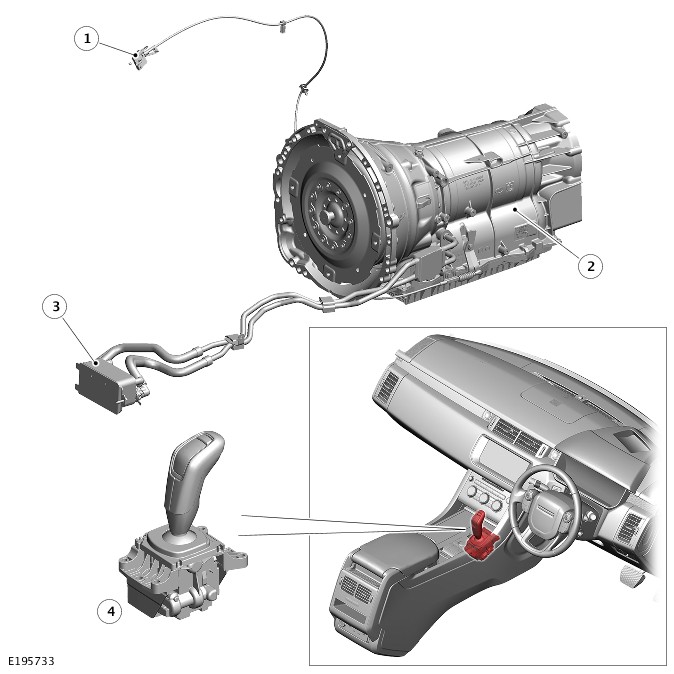
| ITEM | DESCRIPTION |
|---|---|
| 1 | Emergency Park Release (EPR) lever |
| 2 | Automatic transmission |
| 3 | Automatic Transmission Fluid (ATF) cooler |
| 4 | Transmission Control Switch (TCS) |
The ZF 8HP70 transmission is an electronically controlled, hydraulically operated, eight speed automatic unit.
A single unit known as the Mechatronic valve block is located inside the transmission. The Mechatronic valve block contains the following control components:
- Hydraulic control elements
- Electronic control elements
- TCM.
The ZF 8HP70 transmission has the following features:
- Designed to be maintenance free
- Automatic Transmission Fluid (ATF) is 'fill for life'
- The torque converter features a controlled slip feature with electronically regulated control of lock-up, creating a smooth transition to the fully locked condition
- Shift programs controlled by the TCM
- Adaptive Shift Strategy (ASIS), to provide continuous adaptation of shift changes to suit the driving style of the driver, which can vary from sporting to economical
- Connected to the Powertrain Control Module (PCM) via the FlexRay systems bus for communications
- Default mode if major faults occur
- Diagnostics available from the TCM via the FlexRay systems bus.
The transmission selections are made using the linear Transmission Control Switch (TCS) in the floor console. For additional information, refer to:External Controls - Vehicles With: 8HP70 8-Speed Automatic Transmission AWD (307-05A Automatic Transmission/Transaxle External Controls - Vehicles With: 8HP70 8-Speed Automatic Transmission AWD, Description and Operation).
On vehicles featured with the stop/start system, the 8HP70 automatic transmission is fitted with a Hydraulic Impulse Storage (HIS) device to ensure pressurized Automatic Transmission Fluid (ATF) is available to the shift elements as quickly as possible when the engine is started.
TRANSMISSION
The transmission comprises the main casing which houses all of the transmission components. The main casing also incorporates an integral torque converter housing.
A fluid pan is attached to the lower face of the main casing and is secured with bolts. The fluid pan is sealed to the main casing with a gasket. Removal of the fluid pan allows access to the Mechatronic valve block. The fluid pan has magnets located at the rear which collects any ferrous metallic particles present in the transmission fluid.
A fluid filter is located inside the fluid pan. If the Automatic Transmission Fluid (ATF) becomes contaminated or after any service work, the fluid pan with integral filter must be replaced.
The transmission does not have a Bowden cable for park lock operation. This is initiated electronically when the Transmission Control Switch (TCS) is moved to the 'P' park position. An Emergency Park Release (EPR) mechanism is provided to release the park interlock if a failure occurs.
A feature of the eight speed transmission is decoupling of the transmission when the vehicle is at a standstill. Normally the transmission remains in gear with the torque converter slipping and the vehicle is prevented from moving by applying the brake. The new system disengages one of the transmission clutches and only a minimum rotating load remains. This has the effect of further reducing fuel consumption.
The ATF pump is driven by a simplex chain and two drive gears from the input shaft. The ATF pump is a double stroke vane cell pump which delivers 50 cm³ of ATF per revolution.
The integral torque converter housing provides protection for the torque converter assembly and also provides the attachment for the transmission to the engine. The torque converter is a non-serviceable assembly which also contains the lock-up clutch mechanism.
The main casing contains the following major components:
- Input shaft
- Output shaft
- Mechatronic valve block which contains the solenoids, speed sensors and the Transmission Control Module (TCM)
- Three rotating multiplate drive clutches
- Two fixed multiplate brake clutches
- Four planetary gear trains.

| ITEM | DESCRIPTION |
|---|---|
| 1 | Transmission casing |
| 2 | Gear set 1 |
| 3 | Gear set 2 |
| 4 | Gear set 3 |
| 5 | Gear set 4 |
| 6 | Output shaft |
| 7 | Drain plug |
| 8 | Clutch D |
| 9 | Clutch C |
| 10 | Clutch E |
| 11 | Mechatronic valve block |
| 12 | Brake B |
| 13 | Brake A |
| 14 | Fluid filter |
| 15 | Fluid pan |
| 16 | Automatic Transmission Fluid (ATF) pump |
| 17 | Torque converter |
| 18 | Input shaft |
TORQUE CONVERTER

A torsional damper torque converter is used on 8HP70 transmissions.
The torsional damper enables a more direct engine connection for highly efficient power transmission when starting and shifting. The inner spring set is connected directly to the transmission, the outer spring set responds to torque from the engine via the lock-up clutch. When the lock-up clutch is applied, the hydro-dynamic circuit is by-passed and torque is transferred directly to the transmission input shaft. In comparison to conventional torque converters, the torsional damper applies the lock-up clutch earlier. This improves driving comfort at low engine speeds and increases fuel efficiency by enabling the engine to be operated at lower Revolutions Per Minute (RPM) levels.
When the converter lock-up clutch is not applied, torque is transferred hydro-dynamically. Power from the engine is transmitted via the pump and turbine to the transmission input shaft. When the converter lock-up clutch is applied, the hydro-dynamic circuit is by-passed, torque is transferred directly via the lock-up clutch and the twin spring sets. The turbine inertia is coupled between the two spring sets which improves disengagement, helps reduce wear on the transmission and improve noise insulation.
The torque converter is the coupling element between the engine and the transmission and is located in the torque converter housing, on the engine side of the transmission. The driven power from the engine crankshaft is transmitted hydraulically and mechanically through the torque converter to the transmission. The torque converter is connected to the engine by a drive plate attached to the rear of the crankshaft.
The torque converter comprises a torsional damper, an impeller, a stator and a turbine. The torque converter is a sealed unit with all components located between the converter housing cover and the impeller. The two components are welded together to form a sealed, fluid filled housing. With the impeller brazed to the converter housing cover, the impeller is therefore driven at engine crankshaft speed.
The converter housing drive plate has four threaded bosses, which provide for attachment of the engine drive plate. The threaded bosses also provide for location of special tools which are required to remove the torque converter from the torque converter housing.
Lock-Up Clutch
The torque converter lock-up clutch is hydraulically controlled by an Electronic Pressure Regulating Solenoid (EPRS), which is controlled by the Transmission Control Module (TCM). This allows the torque converter to have three states of operation as follows:
- Fully engaged
- Controlled slip variable engagement
- Fully disengaged.
The torque converter pressure valve reduces system pressure and guarantees the pressure needed for the torque converter. It also limits the maximum torque converter pressure, to prevent the torque converter from expanding.
The EPRS is operated by Pulse Width Modulation (PWM) signals from the TCM to give full, partial or no lock-up of the torque converter.
The lock-up clutch is a hydro-mechanical device which eliminates torque converter slip, improving fuel consumption. The engagement and disengagement is controlled by the TCM to allow a certain amount of controlled 'slip'. This allows a small difference in the rotational speeds of the impeller and the turbine which results in improved shift quality. The lock-up clutch comprises a piston and a clutch comprising of friction and steel plates.
In the unlocked condition, the oil pressure supplied to the piston chamber is reduced and the pressure in the turbine chamber is allowed to push the piston back. In this condition the clutch plates are released and torque converter slip is permitted.
In the locked condition, the lock-up clutch spool valves are actuated by the EPRS. Pressurized Automatic Transmission Fluid (ATF) is directed into the lock-up clutch piston. The piston moves with the pressure and pushes the clutch plates together. As the pressure increases, the friction between the clutch plates increases, finally resulting in full lock-up of the clutch plates. In this condition there is direct mechanical drive from the engine crankshaft to the transmission planetary gear train.
The Transmission Idle Control feature is a standstill decoupling feature for the eight speed transmission. When the vehicle comes to a standstill with the brakes applied and the Transmission Control Switch (TCS) is in 'D' (Drive) position, the converter is disconnected from the driveline so that only a slight residual load remains. This further reduces fuel consumption. Decoupling is by actuating clutch B in the transmission, and is dependent on load and output speed.
AUTOMATIC TRANSMISSION FLUID PUMP
The Automatic Transmission Fluid (ATF) pump is an integral part of the transmission. The ATF pump is used to supply hydraulic pressure for the operation of the control valves and clutches. The ATF pump also passes the ATF through the transmission cooler and the transmission to lubricate the gears and shafts.
The ZF 8HP70 ATF pump is a double stroke, vane type pump and is located below the transmission input shaft. The pump is driven by a chain drive from a sprocket located on the torque converter. The pump has a delivery rate of 50 cm³ per revolution. The drive sprocket is driven at engine speed through a splined connection in the torque converter shell.

| ITEM | DESCRIPTION |
|---|---|
| 1 | Vane pump |
| 2 | Chain drive from torque converter cover |

| ITEM | DESCRIPTION |
|---|---|
| 1 | System pressure valve |
| 2 | Automatic Transmission Fluid (ATF) pump |
| 3 | Intake pipe |
| 4 | Oil pan |
| 5 | Pressure pipe |
| 6 | Recycling of redundant fluid |
The Automatic Transmission Fluid (ATF) pump comprises:
- A sprocket
- A rear cover with bearing
- A front cover with bearing
- A cylinder
- A rotor shaft and a rotor with vanes.
A pressure relief valve is fitted in the pressure outlet gallery from the pump, but is not an integral part of the pump itself.
A sprocket is located around the transmission input shaft. Splines on the torque converter nose and the sprocket ensure a positive drive. A simplex chain transmits the rotation of the torque converter cover into rotation of the pump rotor shaft via a second sprocket fitted to the rotor shaft. The gearing of the two sprockets rotates the ATF pump rotor shaft at a speed slightly higher than the Revolutions Per minute (RPM) of the torque converter cover. The torque converter cover is directly connected to the engine crank.
The ATF pump contains seven vanes which are attached to the rotor and rotate within the cam shaped cylinder. As the vanes rotate, the eccentricity of the central hole in the cylinder causes the space between the vanes to increase. This causes a depression between the vanes and fluid is drawn into the space between the vanes via a suction port connected to the fluid pan. The fluid passes through the fluid pan filter before it is drawn into the ATF pump.
As the rotor shaft rotates further, the inlet port is closed by the vanes which have drawn in fluid, trapping the fluid in the space between the vanes. The eccentric hole in the cylinder causes the space between the vanes to decrease and consequentially compresses and pressurizes the fluid trapped between them.
Further rotation of the rotor shaft moves the vanes towards the outlet port. As the vanes pass the outlet port the pressurized fluid passes from the space between the vanes into the pressure gallery to the pressure relief valve.
As the ATF pump is a double stroke vane pump, this sequence is repeated twice per revolution of the rotor shaft.
The pressure relief valve controls the pressure and flow of ATF delivered to the transmission valve block, torque converter and other components. Pressure is controlled by a relief valve which limits the maximum system pressure to 32 bar (464 lbf/in²). The pressure control maintains a constant pressure of ATF irrespective of torque converter input shaft rotational speed. A metering orifice is subject to the pump output pressure. If the pressure in the orifice reaches a predetermined level, a spring loaded ball in the flow control valve is lifted from its seat and pressurized fluid is allowed to recirculate through the pump.
MECHATRONIC VALVE BLOCK
The Mechatronic valve block is located in the bottom of the transmission and is covered by the fluid pan. The valve block houses the following components:
- Transmission Control Module (TCM)
- Electrical actuators
- Speed sensors
- Control valves
- Hydraulic Impulse Storage (HIS) (if fitted).
The above components provide all electro-hydraulic control for all transmission functions.
The Mechatronic valve block comprises the following components:
- TCM
- Seven Electronic Pressure Regulating Solenoids (EPRS)
- Two park lock solenoids
- Twenty one hydraulic spool valves
- Temperature sensor
- Turbine speed sensor
- Output shaft speed sensor
- Hydraulic Impulse Storage (HIS) (if fitted).

| ITEM | DESCRIPTION |
|---|---|
| 1 | Electronic Pressure Regulating Solenoid (EPRS) A - A brake valve |
| 2 | EPRS D - D clutch valve |
| 3 | EPRS B - B brake valve |
| 4 | EPRS E - E clutch valve |
| 5 | Magnetic Valve (MV) 2 - magnet-valve 2 for electrical park interlock (hold out of park) |
| 6 | MV 1 - pressure reducing valve |
| 7 | EPRS SYS - system pressure valve |
| 8 | EPRS WK - Torque converter lock-up clutch valve |
| 9 | EPRS C - C clutch valve |
| 10 | Transmission output shaft speed sensor |
| 11 | Hydraulic Impulse Storage (HIS) (if fitted) |
| 12 | Electrical connector |
| 13 | Transmission Control Module (TCM) - hidden |
Electronic Pressure Regulator Solenoids

Seven Electronic Pressure Regulator Solenoids (EPRS) are located in the valve block. The solenoids are controlled by Pulse Width Modulation (PWM) signals from the Transmission Control Module (TCM). The solenoids convert the electrical signals into hydraulic control pressure proportional to the signal to actuate the spool valves for precise transmission operation.
EPRS A, B, D, E and WK supply a higher control pressure as the signal amperage increases and can be identified by an orange connector cap. The TCM operates the solenoids using PWM signals. The TCM monitors engine load and clutch slip and varies the solenoid duty cycle accordingly. The solenoids have a 12 V operating voltage and a pressure range of 0 - 4.7 bar (0 - 68 lbf.in²).
EPRS C and SYS supply a lower control pressure as the signal amperage increases and can be identified by a gray connector cap. The TCM monitors engine load and clutch slip and varies the solenoid duty cycle accordingly. The solenoids have a 12 V operating voltage and a pressure range of 4.7 - 0 bar (68 - 0 lbf.in²).
The resistance of the solenoid coil winding for EPRS is 5.05 Ohms at 20 °C (68 °F).
Control Solenoid (MV 1)

A shift control solenoid Magnetic Valve 1 (MV1) is located in the valve block. The solenoid is controlled by the Transmission Control Module (TCM) and converts electrical signals into hydraulic control signals to control clutch application.
The shift control solenoid is an open/closed, on/off solenoid which is controlled by the TCM switching the solenoid to earth. The TCM also supplies power to the solenoid. The TCM energizes the solenoid in a programmed sequence for clutch application for gear ratio changes and shift control.
The resistance of the solenoid coil winding for solenoid is between 10 to 11 Ohms at 20 °C (68 °F).
Control Solenoid (MV 2)

| ITEM | DESCRIPTION |
|---|---|
| A | Solenoid in locked (energized) condition - park lock released |
| B | Solenoid in unlocked (de-energized) condition - park lock engaged |
| 1 | Solenoid |
| 2 | Claw - locked |
| 3 | Piston |
| 4 | Claw - unlocked |
A control solenoid Magnetic Valve 2 (MV 2) is located in the valve block. The solenoid is controlled by the Transmission Control Module (TCM) and converts electrical signals into hydraulic control signals to control the electronic park lock function.
The control solenoid is an on/off solenoid which is controlled by the TCM by switching the solenoid to earth.
When the park position is deselected, control solenoid MV2 resets the parking lock valve in the Mechatronic valve block. This is achieved by the TCM providing the ground for the solenoid which is energized, releasing the claws from retaining the park lock piston. Main Automatic Transmission Fluid (ATF) pressure acting on the parking lock piston, pushes the piston back to release the lock.
When the park position is selected, control solenoid MV2 is de-energized. The ATF pressure at the parking lock cylinder piston is vented and the mechanical interlock of the piston is opened. A pre-tensioned torsion spring at the park lock disc pulls the piston into the 'park' position. In the 'park' position the piston engages with the control solenoid claws and is locked in the park position. An emergency release wire cable can be used to release the parking lock manually if an electrical failure occurs.
The resistance of the solenoid coil winding for solenoid is 25 Ohms at 20 °C (68 °F).
When the neutral "N" position is selected and the engine is turned off, the ATF pressure at the park lock cylinder piston is released. The current supply to the control solenoid MV2 remains. The park lock cylinder piston is still held in the unlocked position by the spring force acting on the park lock disc. This prevents the park lock plate from engaging the parking lock. This allows the vehicle to be moved when the engine is not running for a short time. Should the battery voltage fall below the level required to maintain the solenoid in the energized condition, the park lock will be engaged.
Sensors
Speed Sensors
The turbine speed sensor and the output shaft speed sensor are Hall effect type sensors located in the Mechatronic valve block and are not serviceable items. The Transmission Control Module (TCM) monitors the signals from each sensor to determine the input (turbine) speed and the output shaft speed.
The turbine speed is monitored by the TCM to calculate the slip of the torque converter clutch and internal clutch slip. This signal allows the TCM to accurately control the slip timing during shifts and adjust clutch application or release pressure for overlap shift control.
The output shaft speed is monitored by the TCM and compared to engine speed signals received on the FlexRay system bus from the Powertrain Control Module (PCM). Using a comparison of the two signals the TCM calculates the transmission slip ratio for plausibility and maintains adaptive pressure control.
Temperature Sensor
The temperature sensor is also located in the Mechatronic valve block. The Transmission Control Module (TCM) uses the temperature sensor signals to determine the temperature of the transmission fluid. These signals are used by the TCM to control the transmission operation. The TCM uses the temperature signals to promote faster warm-up in cold conditions. The TCM also uses the temperature signal to assist with fluid cooling by controlling the transmission operation when high fluid temperatures are experienced. If the sensor fails, the TCM will use a default value and a fault code will be stored in the TCM.
Spool Valves
The valve block contains spool valves which control various functions of the transmission. The spool valves are of conventional design and are operated by Automatic Transmission Fluid (ATF) pressure.
Each spool valve is located in its spool bore and held in a default (unpressurized) position by a spring. The spool bore has a number of ports which allow ATF to flow to other valves and clutches to enable transmission operation. Each spool has a piston which is waisted to allow ATF to be diverted into the applicable ports when the valve is operated.
When ATF pressure moves a spool, one or more ports in the spool bore are covered or uncovered. ATF is prevented from flowing or is allowed to flow around the applicable waisted area of the spool and into another uncovered port. The ATF is either passed through galleries to actuate another spool, operate a clutch or is returned to the fluid pan.
HYDRAULIC IMPULSE STORAGE (IF FITTED)

| ITEM | DESCRIPTION |
|---|---|
| 1 | Solenoid |
| 2 | Magnetic core |
| 3 | Keeper |
| 4 | Balls |
| 5 | Piston spring |
| 6 | Accumulator cylinder |
| 7 | Piston |
| 8 | One-way restrictor |
| 9 | Inlet/outlet port |
| 10 | Piston ATF volume |
| 11 | Keeper spring |
| 12 | Electrical connector |
The Hydraulic Impulse Storage (HIS) system if fitted to vehicles with the auto stop/start system.
The HIS system comprises a cylindrical accumulator which contains an electro-mechanical locking unit, a spring actuated piston and a one-way restrictor. The accumulator is located at the rear of the Mechatronic valve block and is secured in position with three screws and sealed into a port in the transmission casing with an O-ring seal.
The electro-mechanical locking unit comprises a low-current solenoid, a spring loaded keeper incorporating a magnetic core and a number of balls. The keeper has a detent into which the balls locate during filling of the HIS when the engine is running and the Automatic Transmission Fluid (ATF) pump is producing pressure.
The one-way restrictor is located in the inlet/outlet port of the accumulator. The restrictor provides a controlled charging of the HIS, to allow a small volume flow of ATF. This ensures that the operation of the transmission shift elements are not compromised by a sudden drop in ATF pressure. The restrictor allows a charging time for the HIS of approximately 5 seconds. When discharge is required, the restrictor allows full flow from the cylinder.
The filling process for the HIS has several steps:
- When the engine is running and the ATF pump is producing pressure, the one-way restrictor allows a controlled flow of ATF which acts on the piston.
- The ATF pressure moves the piston into the accumulator cylinder. A locking ring on the piston passes over the balls which are at this point located in the keeper detent.
- As the piston continues to move, a spring in the center of the keeper moves the locking cylinder and the magnetic core towards the solenoid windings and into the final fully charged position. The energized solenoid holds the magnetic core and the balls are lifted from the detent by the movement of the keeper, locking the piston in the charged position. The HIS is now electro-mechanically locked and ready for an engine stop to occur.
- When the engine is stopped, the ATF pump also stops and ATF pressure is decayed. The pressure acting on the piston is also decayed and the piston moves to be held in the locked position by the balls. The energy required for hydraulic filling during engine start is now stored in the tensioned piston spring. The solenoid remains energized to hold the keeper in position and the balls out of the detent to lock the piston.
Charging

Charged

Engine start process:
- When the engine is restarted, the solenoid holding current is removed, which starts the unlocking process.
- The magnetic core is released and the keeper is moved towards the piston under spring pressure. The balls fall into the detent in the keeper, releasing the piston.
- The piston is moved under spring pressure, pushing out the volume of ATF. The one-way restrictor opens fully to allow unrestricted flow of ATF from the accumulator cylinder into the transmission housing. The process is completed between 300 and 350 ms.
- Once the engine is started, the ATF pump produces flow and pressure to provide seamless transmission shift element engagement as soon as the engine is started.
Discharging

DRIVE CLUTCHES

| ITEM | DESCRIPTION |
|---|---|
| 1 | Input shaft |
| 2 | Main pressure supply port |
| 3 | Piston |
| 4 | Cylinder – external plate carrier |
| 5 | Clutch plate assembly |
| 6 | Baffle plate (for clutch, not brake) |
| 7 | Diaphragm spring |
| 8 | Output shaft |
| 9 | Bearing |
| 10 | Dynamic pressure equalization chamber |
| 11 | Piston chamber |
| 12 | Lubrication channel |
There are three drive clutches and two brakes used in the transmission. Each clutch comprises a number of friction plates dependent on the output controlled. A typical clutch consists of a number of alternating steel plates and plates with friction material bonded to each face.
The clutch plates are held apart mechanically by a diaphragm spring and hydraulically by dynamic pressure. The pressure is derived from a lubrication channel which supplies fluid to the bearings and clutch cooling. The fluid is passed via a drilling in the input shaft into the chamber between the baffle plate and the piston. To prevent inadvertent clutch application due to pressure build up produced by centrifugal force, the fluid in the dynamic pressure equalization chamber overcomes any centrifugal pressure in the piston chamber and holds the piston off the clutch plate assembly.
When clutch application is required, main pressure from the Automatic Transmission Fluid (ATF) pump is applied to the piston chamber from the supply port. This main pressure overcomes the low pressure fluid present in the dynamic pressure equalization chamber. The piston moves, against the pressure applied by the diaphragm spring, and compresses the clutch plate assembly. When the main pressure falls, the diaphragm spring pushes the piston away from the clutch plate assembly, disengaging the clutch.
PLANETARY GEAR TRAINS
The eight forward gears and the reverse gear are produced by a combination of four simple planetary gear sets, three clutches and two brakes. The front two gear sets share a common sun gear. Power is output always through the planetary carrier of the fourth gearset.
Five shift elements comprising three clutches and two brakes, are responsible for all eight forward and reverse gears. High efficiency is achieved by the use of only two shift elements disengaged in each gear which reduces drag and so increases the efficiency.
Planetary Gear Sets 1, 2 and 3
The planetary gear sets 1 and 2 comprise:
- Sunwheel - shared by both gear sets
- Three or four planetary gears per gear set
- NOTE: Ingenium I4 2.0L Diesel engine fitment has three planetary gears in gearset 2, all other engine variants have four planetary gears.
- Planetary gear carrier (spider) per gear set
- Ring gear per gear set.
The planetary gear set 3 comprises:
- Sunwheel
- Three planetary gears
- Planetary gear carrier (spider)
- Ring gear.

| ITEM | DESCRIPTION |
|---|---|
| 1 | Planetary gears - gear set 1 |
| 2 | Ring gear - gear set 1 |
| 3 | Planetary gear carrier (spider) |
| 4 | Planetary gears - gear set 2 |
| 5 | Ring gear - gear set 2 |
| 6 | Planetary gears - gear set 3 |
| 7 | Ring gear - gear set 3 |
| 8 | Sun wheel - gear set 3 |
| 9 | Sun wheel - joint gear sets 1 and 2 |
Planetary Gear Set 4
The planetary gear set 4 comprises:
- Sunwheel
- Four planetary gears
- Planetary gear carrier (spider) - output shaft
- Ring gear.

| ITEM | DESCRIPTION |
|---|---|
| 1 | Ring gear |
| 2 | Planetary gears |
| 3 | Output shaft / gear carrier |
| 4 | Sun wheel |
TRANSMISSION CONTROL MODULE
The Transmission Control Module (TCM) is an integral part of the Mechatronic valve block which is located at the bottom of the transmission, within the fluid pan. The TCM is the main controlling component of the transmission.
The TCM processes signals from the transmission speed and temperature sensors, Powertrain Control Module (PCM) and other vehicle systems. From the received signal inputs and pre-programmed data, the module calculates the correct gear, torque converter clutch setting and optimum pressure settings for gear shift and lock-up clutch control.
POWER FLOWS
Operation of the transmission is controlled by the Transmission Control Module (TCM), which electrically activates various solenoids to control the transmission gear selection. The sequence of solenoid activation is based on programmed information in the TCM memory and physical transmission operating conditions such as:
- Vehicle speed
- Throttle position
- Engine load
- Transmission Control Switch (TCS) position.
All gear shifts from 1st to 8th and 8th to 1st are known as 'overlap' shifts. Overlap shifts are during a gear shift one clutch must remain capable of transmitting torque at a reduced main pressure until the other clutch is ready to accept the torque.
Engine torque is transferred, via operation of single or combinations of clutches to the 4 planetary gear trains. All gear trains are controlled by reactionary inputs from brake clutches to produce the eight forward gears and one reverse gear. The ratios are as follows:
| GEAR | 1ST | 2ND | 3RD | 4TH | 5TH | 6TH | 7TH | 8TH | REVERSE |
|---|---|---|---|---|---|---|---|---|---|
| Ratio | 4.714 | 3.143 | 2.106 | 1.667 | 1.285 | 1.000 | 0.839 | 0.667 | 3.317 |

| ITEM | DESCRIPTION |
|---|---|
| 1 | Brake A |
| 2 | Brake B |
| 3 | Gear set 1 |
| 4 | Gear set 2 |
| 5 | Gear set 3 |
| 6 | Clutch E |
| 7 | Clutch C |
| 8 | Clutch D |
| 9 | Gear set 4 |
The shift elements, clutches and brakes are actuated hydraulically. Fluid pressure is applied to the required clutch and/or brake, pressing the plates together and allowing drive to be transmitted through the plates. The purpose of the shift elements is to perform power-on shifts with no interruption to traction and smooth transition between gear ratios.
INSTRUMENT CLUSTER
The virtual display Instrument Cluster (IC) is connected to the Body Control Module/Gateway Module (BCM/GWM) on the High Speed (HS) Controller Area Network (CAN) comfort systems bus. The Transmission Control module (TCM) is connected to the BCM/GWM on the FlexRay systems bus.
Automatic transmission status is transmitted from the TCM to the virtual display IC via the BCM/GWM. Transmission status is indicated to the driver by a message in the message center or illumination of a warning indicator. For additional information, refer to:Instrument Cluster (413-01 Instrument Cluster, Description and Operation).
The Thin Film Transistor (TFT) display instrument cluster is connected to the TCM via the HS CAN powertrain systems, the BCM/GWM and the FlexRay systems bus. Transmission status is transmitted by the TCM and displayed to the driver in one of two displays in the instrument cluster. For additional information, refer to:Instrument Cluster (413-01 Instrument Cluster, Description and Operation).
Malfunction Indicator Lamp
The Malfunction Indicator Lamp (MIL) is located in the virtual display Instrument Cluster (IC). Transmission related faults which may affect the vehicle emissions will illuminate the MIL.
The MIL is illuminated by the Powertrain Control Module (PCM) on receipt of a relevant fault message from the Transmission Control Module (TCM) on the FlexRay system bus. The nature of the fault can be diagnosed using approved diagnostic equipment which reads the fault codes stored in the TCM memory.
Transmission Status Display
The transmission status display is located in the virtual display Instrument Cluster. The display shows the Transmission Control Switch (TCS) or the selected gear when in manual and sport modes.
The following table shows the displays and their descriptions.
| SYMBOL | DESCRIPTION |
|---|---|
| P | Park selected |
| R | Reverse selected |
| N | Neutral selected |
| D* | Drive and temporary manual mode selected (* = current gear) |
| S* | Sport mode selected (* = current gear) |
| 1 | 1st gear selected (manual CommandShift mode) |
| 2 | 2nd gear selected (manual CommandShift mode) |
| 3 | 3rd gear selected (manual CommandShift mode) |
| 4 | 4th gear selected (manual CommandShift mode) |
| 5 | 5th gear selected (manual CommandShift mode) |
| 6 | 6th gear selected (manual CommandShift mode) |
| 7 | 7th gear selected (manual CommandShift mode) |
| 8 | 8th gear selected (manual CommandShift mode) |
Message Center
The message center is located in the virtual display Instrument Cluster (IC). The message center display relays vehicle status and operating information to the driver and can display messages relating to a number of vehicle systems. If a transmission fault occurs, the message GEARBOX FAULT is displayed in the message center. For additional information, refer to:Instrument Cluster (413-01 Instrument Cluster, Description and Operation).
TRANSMISSION CONTROL MODULE
The Transmission Control Module (TCM) outputs signals to control the hydraulic operation of the transmission. Signals are sent to the shift control solenoid valves and the Electronic Pressure Regulating Valve's (EPRS).
The TCM processes signals from the transmission speed and temperature sensors, the Transmission Control Switch (TCS), the Powertrain Control Module (PCM) and other vehicle systems. From the received signal inputs and pre-programmed data, the TCM calculates the:
- Correct gear
- Torque converter clutch setting
- Optimum pressure settings for gear shift and lock-up clutch control.
The PCM supplies the engine management data over the FlexRay systems bus. The TCM requires engine data to efficiently control the transmission operation, for example:
- Flywheel torque
- Engine speed
- Accelerator pedal angle
- Engine temperature.
The steering angle sensor and the Anti-lock Brake System (ABS) control module also supply data to the TCM on the FlexRay systems bus. The TCM uses data from these systems to suspend gear changes when the vehicle is cornering and/or the ABS control module is controlling braking or traction control.
The Body Control Module/Gateway Module (BCM/GWM) supplies steering wheel paddle data over the FlexRay systems bus. The TCM uses this to schedule driver requested upshifts and downshifts.
Using the signal inputs and the memorized data, the TCM control program computes:
- the correct gear and torque converter lock-up clutch setting
- the optimum pressure settings for gear shift and lock-up clutch control.
Special output-side modules (power output stages, current regulator circuits), allow the TCM to control the solenoid valves and pressure regulators. This allows precise control the hydraulics of the automatic transmission. In addition, the amount and duration of engine interventions are supplied to the engine management via the FlexRay systems bus.
The TCM determines the position of the TCS using signals from the TCS via the High Speed (HS) Controller Area Network (CAN) systems bus.
The TCM transmits the position of the TCS and any manual gear selected on the FlexRay systems bus to the BCM/GWM. This information is shown in the gear selector display in the instrument cluster.
Engine Stall
If the engine stalls it will coast down in gear, with the transmission providing drive to the engine. A restart can be attempted at this point and the engine may start and the driver can continue.
If the coast down speed reduces such that the speed of the engine is less than 100 Revolutions Per Minute (RPM), the transmission will go to neutral, D illumination will flash in the instrument cluster. The driver needs to select neutral or park and then press the brake pedal to restart the engine.
If the start/stop switch is pressed when driving, the message ENGINE STOP BUTTON PRESSED is displayed in the message center but there will be no change to the ignition state. If the driver requires to switch off the engine, the start/stop switch must be pressed for a second time. The engine will be stopped and will be back driven by the transmission as the vehicle coasts down.

A = HARDWIRED: AN = HIGH SPEED (HS) CONTROLLER AREA NETWORK (CAN) POWERTRAIN SYSTEMS BUS: AP = HS CAN COMFORT SYSTEMS BUS: AX = FLEXRAY SYSTEMS BUS.
| ITEM | DESCRIPTION |
|---|---|
| 1 | Transmission Control Module (TCM) |
| 2 | Transmission Control Switch (TCS) |
| 3 | Powertrain Control Module (PCM) |
| 4 | Anti-lock Brake System (ABS) control module |
| 5 | Body Control Module/Gateway Module (BCM/GWM) assembly |
| 6 | Instrument Cluster (IC) |
| 7 | Mechatronic valve block |
| 8 | TCS |
| 9 | Ground |
| 10 | Permanent power supply from Engine Junction Box (EJB) |
| 11 | Power supply from ignition relay in EJB |
DIAGNOSTICS - VEHICLES WITH: 8HP70 8-SPEED AUTOMATIC TRANSMISSION AWD (G2718648)
For a detailed description of the automatic transmission/transaxle system and operation, refer to the relevant Description and Operation sections in the workshop manual. REFER to:Transmission Description (307-01A Automatic Transmission/Transaxle - Vehicles With: 8HP70 8-Speed Automatic Transmission AWD, Description and Operation).
The vehicle should not be driven if the fluid level is low as this can result in internal damage.
The transmission fluid temperature must not be allowed to exceed 50°C (122°F) when checking level. Should the temperature rise above this figure, abort the check and allow the transmission fluid to cool to below 30°C (86°F).
This vehicle is not equipped with a fluid level indicator. An incorrect level may affect the transmission operation and could result in transmission damage. To check and add fluid to the transmission, refer to the relevant section in the workshop manual. REFER to General Procedures - Transmission Fluid Level Check.
HIGH FLUID LEVEL
A fluid level that is too high may cause the fluid to become aerated due to the churning action of the rotating internal parts. This will cause erratic control pressure, foaming, loss of fluid from the breather and possible transmission damage. If an overfill condition is identified, with the engine at idle make sure the fluid temperature is within the specified range and allow the excess fluid to drain until a small thread of fluid runs from the filler/level plug hole.
LOW FLUID LEVEL
A low fluid level could result in poor transmission engagement, slipping, or damage. Refer to the oil leak detection process in this document to aid diagnosis.
ADDING FLUID
The use of any other type of transmission fluid other than that specified can result in transmission damage.
If fluid needs to be added, follow the fill process shown in the relevant section in the workshop manual. REFER to General Procedures - Transmission Fluid Level Check.Do not overfill the fluid.
For fluid type, refer to the Specification section in the workshop manual.
FLUID CONDITION CHECK
- Check the fluid level. Refer to the relevant section in the workshop manual. REFER to General Procedures - Transmission Fluid Level Check.
- Observe the color and the odor of the fluid. The color under normal circumstances should be like honey, not dark brown or black.
- Allow the fluid to drip onto a facial tissue and examine the stain.
- If evidence of solid material is found, the transmission fluid pan should be removed for further inspection.
NOTE: In the event of a transmission unit replacement for internal failure, the oil cooler and pipes must also be replaced.
Diagnosis by substitution from a donor vehicle is NOT acceptable. Substitution of control modules does not guarantee confirmation of a fault, and may also cause additional faults in the vehicle being tested and/or the donor vehicle.
- Verify the customer concern.
- Visually inspect for obvious signs of damage and system integrity.
Visual Inspection
| MECHANICAL | ELECTRICAL | HYDRAULIC |
|---|---|---|
|
|
|
- Check JLR claims submission system for open campaigns. Refer to the corresponding bulletins and SSMs which may be valid for the specific customer complaint and complete the recommendations as required.
- If the cause is not visually evident check for Diagnostic Trouble Code(s) (DTC)s and refer to the DTC Index.
- If an obvious cause for an observed or reported concern is found, correct the cause (if possible) before proceeding to the next step.
Vibration from the transmission may be caused by the installation of incorrect front/rear drive units. Refer to Sections 205-02 and 205-03 for further guidance on how to diagnose and rectify this issue.
Symptom Chart
| SYMPTOM | POSSIBLE SOURCES | ACTION |
|---|---|---|
| Oil leak from underneath the vehicle or a leak is discovered during routine service | Oil leak | Follow the service instruction below |
SERVICE INSTRUCTION
Be aware that oil leaks from above the transmission will cause oil to collect on the transmission oil pan for example engine leaks, oil cooler pipe leaks, even diesel fuel leak.
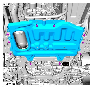
- Remove the transmission undershield to gain access to the transmission area. REFER to Workshop Manual Section 501-02.
- Using a suitable degreaser, thoroughly clean the transmission to make sure all oil contamination is removed. Refer to the Oil Leak Inspection section in this document. Make sure all relevant areas are free of oil, contamination before progressing. Make sure there is no residual oil left in bolt holes etc. If necessary, use an air blower to clear and dry the bolt holes on the sump pan.
If there is an oil to leak between the automatic transmission and the transfer case, this may be due to internal porosity of the automatic transmission case.


Due to capillary action, oil residue may be found in the joint between the transmission case and the oil pan. The potential leak path is shown in the illustration below.

Other potential leak sources are the transmission oil cooler pipe unions. Visually inspect the areas shown in the illustration below.
The bracket securing the transmission oil pipes has been removed to provide extra clarity.

The potential leak path is shown in the illustration below.

Leak detector spray is available to order on the JLR Electronics Parts Catalogue.
- Thoroughly coat the potential leak locations using a suitable leak detector spray, refer to the illustrations above.
- Run the vehicle up to operating temperature, raise the ramp and use a suitable inspection lamp to identify the source of the transmission oil leak.
- Identify the source of the oil leak and take clear, in focus pictures. These may be required to support your warranty claim.
- When the source of the leak has been identified, refer to the relevant technical bulletin or refer to the relevant section of the workshop manual and repair as necessary. If the source of the leak is not shown in the illustrations above, report using an Electronic Product Quality Report (EPQR). Make sure to attach clear, in focus pictures showing the use of leak detection spray and the exact position of the leak.
Affected Vehicle Range
| MODEL: | MODEL YEAR: | VEHICLE IDENTIFICATION NUMBER (VIN): | ASSEMBLY PLANT: | APPLICABILITY: |
|---|---|---|---|---|
| Range Rover Sport (LW) | 2017-2018 | 124031-199999 | Solihull | Vehicles With: 8HP70 8-Speed Automatic Transmission All Wheel Drive (AWD)/8HP45 8-Speed Automatic Transmission AWD |
| Range Rover Sport (LW) | 2018 | 400000-411938 | Solihull | Vehicles With: 8HP70 8-Speed Automatic Transmission AWD/8HP45 8-Speed Automatic Transmission AWD |
| Range Rover Sport (LW) | 2017-2018 | 659468-699999 | Solihull | Vehicles With: 8HP70 8-Speed Automatic Transmission AWD/8HP45 8-Speed Automatic Transmission AWD |
| Range Rover Sport (LW) | 2017-2018 | 800000-806735 | Solihull | Vehicles With: 8HP70 8-Speed Automatic Transmission AWD/8HP45 8-Speed Automatic Transmission AWD |
| Range Rover (LG) | 2017-2018 | 320324-507907 | Solihull | Vehicles With: 8HP70 8-Speed Automatic Transmission AWD/8HP45 8-Speed Automatic Transmission AWD |
| Range Rover Velar (LY) | 2018 | 700000-776521 | Solihull | Vehicles With: 8HP70 8-Speed Automatic Transmission AWD/8HP45 8-Speed Automatic Transmission AWD |
| Discovery (LR) | 2017-2018 | 000001-073283 | Solihull | Vehicles With: 8HP70 8-Speed Automatic Transmission AWD/8HP45 8-Speed Automatic Transmission AWD |
A customer may express a concern that the DRIVE (D) lamp will flash on the TCS and/or Instrument Cluster (IC) following an Auto stop/start event. DTCs P0715-64 and P0700-02 may be stored in the Transmission Control Module (TCM). Also, a 'Gearbox Fault' warning message may be displayed on the IC.
Software error.
Should a customer express a concern, follow the diagnostic procedure below.
This procedure requires Pathfinder version 188 loaded or a later version.
The Jaguar Land Rover (JLR) diagnostic tool will read the correct VIN for the current vehicle and automatically take the vehicle out of ‘Transportation mode’ if required.
- Connect the JLR approved battery support unit.
- Connect the JLR approved tool to the vehicle and begin a new diagnostic session.
- Follow the JLR approved diagnostic tool prompts.
- Select 'ECU Diagnostics'.
- Select 'All DTCs'.
- If the only DTCs stored within the Transmission Control Module (TCM) are P0715-64 and/or P0700-02, continue to step 7.
- Any DTCs stored within the TCM, other than P0715-64 and/or P0700-02 must be investigated and rectified, before continuing. Refer to TOPIx workshop manual section 100-00: DTC Index Transmission Control Module (TCM).
- Select 'Clear all DTCs'.
- Select 'ECU Diagnostics'.
- Select 'Transmission Control Module [TCM]'.
- Select 'Update ECU'.
- Follow all on-screen instructions to complete the task.
- If required, reset the vehicle to ‘Transportation mode’.
- When all of the tasks are complete, exit the current session.
- Disconnect the JLR approved diagnostic equipment and the JLR approved battery support unit.
For a list of Diagnostic Trouble Codes that could be set on this vehicle, please refer to Section 100-00. REFER to:Diagnostic Trouble Code Index - DTC: Transmission Control Module (TCM) (100-00 General Information, Description and Operation
AUTOMATIC TRANSMISSION/TRANSAXLE - VEHICLES WITH: 8HP70 8-SPEED AUTOMATIC TRANSMISSION AWD
TRANSMISSION OIL COLOR CHART (G2721476)
Transmission Oil Color Chart


Transmission Oil Color Chart


Repairs
AUTOMATIC TRANSMISSION/TRANSAXLE - VEHICLES WITH: 8HP70 8-SPEED AUTOMATIC TRANSMISSION AWD
TRANSMISSION - TDV6 3.0L DIESEL (G2356698)
| Name | Quantity | Part Number |
|---|---|---|
| Driveshaft flange bolts 1, 2 | 4 | TYG500130 |
| Driveshaft flange bolts 1, 2 | 6 | TYG500141 |
| EGR inlet pipe to exhaust gasket | 1 | LR078958 |
| Engine compartment brace bolts | 8 | LR037935 |
| Left exhaust downpipe gasket | 1 | LR016619 |
| Right exhaust downpipe gasket | 1 | LR016621 |
| Torque converter bolts | 4 | LR038661 |
| Transfer case input shaft oil seal | 1 | LR086041 |
| Transmission fluid cooler tubes to transmission O-ring seals | 2 | LR049457 |
| Name | Quantity | Part Number | VIN range from | VIN range to |
|---|---|---|---|---|
| Transmission | 1 | LR082672 | HA000001 | |
| Transmission | 1 | LR082675 | HA000001 | |
| Transmission | 1 | LR043325 | ||
| Transmission | 1 | LR071402 | GA000001 | GA999999 |
| Transmission | 1 | LR075290 | GA000001 | GA999999 |
| Transmission | 1 | LR087234 | HA000001 | |
| Transmission | 1 | LR062465 | FA000001 | FA999999 |
| Transmission | 1 | LR036585 | FA999999 | |
| Transmission | 1 | LR078391 | GA000001 |
| Name | Quantity | Part Number | VIN range from | VIN range to |
|---|---|---|---|---|
| Transmission | 1 | LR044435 | ||
| Transmission | 1 | LR062464 | FA000001 | FA999999 |
| Transmission | 1 | LR036588 | FA999999 |
| Adapter, Wrench
303-1069
|
 |
| Cutter, Exhaust Pipe 1, 2
100-051
|
 |
| Installer, Oil Seal
308-598
|
 |
| Post Selective Catalyst Reduction Soot Sensor - Remover/Installer
JLR-303-1646
|
 |
| Remover, Driveshaft
205-932
|
 |
| Remover/Installer, Driveshaft Nut
JLR-205-993
|
 |
| Remover/Installer, NOx/Oxygen Sensor
JLR-303-1666
|
 |
| Viscous Coupling Wrench
303-1142
|
 |
| Wrench, H02S
310-121
|
 |
| Wrench, Transmission Filler Plug
307-452
|
 |
PUBLISHED: 20-APR-2020
2017.0 RANGE ROVER SPORT (LW), 307-01A
AUTOMATIC TRANSMISSION/TRANSAXLE - VEHICLES WITH: 8HP70 8-SPEED AUTOMATIC TRANSMISSION AWD
TRANSMISSION - TDV6 3.0L DIESEL /TDV6 3.0L DIESEL - GEN 1.5/TDV6 3.0L DIESEL - GEN 2, VEHICLES WITH: TWIN SPEED TRANSFER CASE (G1509720)
- 44.20.01
- AUTOMATIC TRANSMISSION - RENEW
- 3000 CC, TDV6, DIESEL, WITH PARTICULATE FILTER, WITH DIESEL EXHAUST FLUID, IC
- 6.10
- USED WITHINS
SPECIAL TOOL(S)

303-1069
Adapter, Wrench

308-598
Installer, Oil Seal
PART(S)
| STEP | PART NAME | QUANTITY |
|---|---|---|
| Step 4 | Transfer case input shaft oil seal | 1 |
| Step 16 | Torque converter bolts | 4 |
| Step 24 | Transmission fluid cooler tubes to transmission O-ring seals | 2 |
| Step 37 | Rear driveshaft constant velocity joint bolts | 6 |
| Step 38 | Driveshaft flange bolts | 4 |
-
Some variation in the illustrations may occur, but the essential information is always correct.
-
Some illustrations may show the transmission removed for clarity.


-
CAUTION:
Oil seals must be installed dry.
NOTES:-
This step is only required if previously removed.
-
Make sure that this component is installed to the noted removal position.
Special Tool(s): 308-598 -


-
NOTE:
This step is only required if previously removed.
-
Special Tool(s): 303-1069
- Clean the component mating faces.
- Lubricate input shaft splines with 'Weicon TL7391' grease.
-
Torque: 45Nm
-

-
CAUTIONS:
-
To prevent water ingress and subsequent transmission damage, make sure that the breather is fully pushed home into the transmission casing. The white line around the circumference of the pipe should not be visible when correctly installed.
-
Remove the blanking plugs.
NOTE:This step is only required if a new component is installed.
-


-
WARNING:
Make sure that the transmission is secured with suitable retaining straps.
CAUTIONS:-
Apply grease of the correct specification to the torque converter spigot.
-
Make sure that the torque converter remains in the transmission.
-
Remove and discard the cable ties securing the torque converter.
NOTE:This step requires the aid of other technicians.
Using a suitable hydraulic jack, support the transmission. -


-
Refer to:Front Driveshaft - TDV6 3.0L Diesel /TDV6 3.0L Diesel - Gen 1.5/TDV6 3.0L Diesel - Gen 2 (205-01 Driveshaft, Removal and Installation).
-
Refer to:Exhaust System - Vehicles Without: Diesel Particulate Filter (DPF) (309-00A Exhaust System - TDV6 3.0L Diesel - Gen 2, Removal and Installation).Refer to:Exhaust System - Vehicles With: Diesel Particulate Filter (DPF) (309-00A Exhaust System - TDV6 3.0L Diesel - Gen 2, Removal and Installation).Refer to:Exhaust System - Vehicles With: Diesel Exhaust Fluid (309-00A Exhaust System - TDV6 3.0L Diesel - Gen 2, Removal and Installation).

- Lower the vehicle.

-
Refer to:Secondary Bulkhead Center Panel - TDV6 3.0L Diesel /TDV6 3.0L Diesel - Gen 1.5/TDV6 3.0L Diesel - Gen 2 (501-02 Front End Body Panels, Removal and Installation).
- Connect the battery ground cable.
Refer to:Specifications (414-01 Battery, Mounting and Cables, Specifications).
- Check the transmission fluid leve.
Refer to:Transmission Fluid Level Check - TDV6 3.0L Diesel /TDV8 4.4L Diesel (307-01A Automatic Transmission/Transaxle - Vehicles With: 8HP70 8-Speed Automatic Transmission AWD, General Procedures).
-
-
If a new Transmission Assembly is installed. The Jaguar Land Rover approved diagnostic equipment must be used to calibrate the module.NOTE:
Vehicles to the end of 17MY.
-
If a new Transmission Assembly is installed. The Jaguar Land Rover approved diagnostic equipment must be used to calibrate the module.NOTE:
Vehicles from introduction of 18MY.
- Select 'Transmission Control Module [TCM]'
- Select 'Replace ECU'
- Follow all on-screen instructions to complete this task.
-
AUTOMATIC TRANSMISSION/TRANSAXLE - VEHICLES WITH: 8HP70 8-SPEED AUTOMATIC TRANSMISSION AWD
TRANSMISSION FLUID LEVEL CHECK - TDV6 3.0L DIESEL /TDV8 4.4L DIESEL (G1535465)
- 44.24.06
- TRANSMISSION FLUID LEVEL CHECK
- 3000 CC, TDV6
- 0.70
- USED WITHINS
SPECIAL TOOL(S)

307-452
Wrench, Transmission Filler Plug


-
Observe due care when draining, as the fluid can be very hot.
-
Observe due care when working near a hot exhaust system.
-
- The following steps must be observed before starting the transmission fluid level check.
- The vehicle must be on a horizontal ramp.
- Make sure that the electric park brake (EPB) is applied.
- Make sure the transmission control switch (TCS) is in the Park (P) position.
-
CAUTION:
Using Land Rover approved diagnostic equipment, make sure the transmission temperature is between is 30°C (85°F) and 50°C (122°F) before starting the fluid level check.
- Connect Land Rover approved diagnostic equipment to the vehicle.
- Start the engine and allow to idle.
- Switch off the air conditioning (A/C) system and other electrical components.
-
- Make sure that the transmission is not in the default mode, if this is the case, stop and correct the cause first and then restart the fluid level check.
-
CAUTION:
Make sure the hydraulic control system is filled with oil.
- Apply and hold the brake pedal.
- Select reverse gear and wait for 10 seconds.
- Select drive, then manual 1st gear and wait for 10 seconds.
- Select 2nd gear and wait for 10 seconds.
- Select Park (P) on the TCS.
-
NOTE:
Make sure the torque converter is completely filled with oil.
- Raise the engine speed to 2000 rpm and hold for 30 seconds. Then return to idle speed.
-
NOTE:
After completing the preparation, proceed to the actual transmission fluid level check.
- If the transmission oil temperature is lower than 30°C (86°F). Allow the transmission to warm up above 30°C (86°F) with the engine idling in the P position, then proceed with the transmission fluid level check.
- If the transmission oil temperature is above 50°C (122°F), switch off the engine and allow the transmission to cool down, then restart the fluid level check.
-
CAUTION:
Only continue with the fluid level check if the transmission temperature is between 30°C (86°F) 50°C (122°F).
- Start the engine, if not already idling.
- Maintain the engine idle speed.
-
Raise and support the vehicle.WARNING:
Make sure to support the vehicle with axle stands.



-
CAUTION:
Make sure the correct specification and quantity of oil is used.
NOTE:Use transmission fluid meeting Land Rover specification.
- Fill oil through the overflow hole until the level inside is high enough that oil starts to trickle back out of the same hole.
Refer to:Specifications (307-01A Automatic Transmission/Transaxle - Vehicles With: 8HP70 8-Speed Automatic Transmission AWD, Specifications).
- Fill oil through the overflow hole until the level inside is high enough that oil starts to trickle back out of the same hole.


-
NOTE:
Install the original oil filler plug.
- Using the special tool, install the original oil filler plug.
-
Special Tool(s): 307-452

-
CAUTION:
Make sure the transmission fluid fill plug is tightened to the correct specification. Failure to follow this instruction may result in damage to the transmission.
- To make sure the transmission fill plug is torqued to the correct specification. Using the special tool and torque wrench the following calculation steps must be followed.
- Step 1. Multiply 35 Nm by the effective length of the torque wrench (1).
- Step 2. Add the effective length of the special tool (2) to the effective length of the torque wrench (1).
- Step 3. Divide the total of step 1 by the total of step 2.
- Step 4. Set the torque wrench to the figure arrived at in step 3.
- Tighten the transmission fluid fill plug to the torque given by the calculation.

-
- Remove the special tool.
-
Special Tool(s): 307-452
-
Remove the container.CAUTION:
Clean the area around the filler plug, wipe away any excess fluid.
- Lower the vehicle.
- Disconnect the diagnostic tool.
AUTOMATIC TRANSMISSION/TRANSAXLE - VEHICLES WITH: 8HP70 8-SPEED AUTOMATIC TRANSMISSION AWD
TRANSMISSION FLUID LEVEL CHECK (G1962079)
- 44.24.06
- TRANSMISSION FLUID LEVEL CHECK
- 3000 CC, TDV6
- 0.70
- USED WITHINS
SPECIAL TOOL(S)
307-452
Wrench, Transmission Filler Plug
-
Observe due care when draining, as the fluid can be very hot.
-
Observe due care when working near a hot exhaust system.
- The following steps must be observed before starting the transmission fluid level check.
-
CAUTION:
Using Land Rover approved diagnostic equipment, make sure the transmission temperature is between is 30°C (85°F) and 50°C (122°F) before starting the fluid level check.
- Connect Land Rover approved diagnostic equipment to vehicle.
- Start the engine and allow to idle.
- Switch off the air conditioning (A/C) system and other electrical components.
-
- Make sure that the transmission is not in the default mode, if this is the case, stop and correct the cause first and then restart the fluid level check.
-
CAUTION:
Make sure the hydraulic control system is filled with oil.
- Apply and hold the brake pedal.
- Select reverse gear and wait for 10 seconds.
- Select drive, then manual 1st gear and wait for 10 seconds.
- Select 2nd gear and wait for 10 seconds.
- Select Park (P) on the TCS.
-
NOTE:
Make sure the torque converter is completely filled with oil.
- Raise the engine speed to 2000 rpm and hold for 30 seconds. Then return to idle speed.
-
NOTE:
After completing the preparation, proceed to the actual transmission fluid level check.
- If the transmission oil temperature is lower than 30°C (86°F). Allow the transmission to warm up above 30°C (86°F) with the engine idling in the P position, then proceed with the transmission fluid level check.
- If the transmission oil temperature is above 50°C (122°F), switch off the engine and allow the transmission to cool down, then restart the fluid level check.
-
CAUTION:
Only continue with the fluid level check if the transmission temperature is between 30°C (86°C) 50°C (122°).
- Start the engine, if not already idling.
- Maintain the engine idle speed.
-
Raise and support the vehicle.WARNING:
Make sure to support the vehicle with axle stands.

-
NOTE:
Install the original oil filler plug.
- Using the special tool, install the original oil filler plug.
-
Special Tool(s): 307-452
-
CAUTION:
Make sure the transmission fluid fill plug is tightened to the correct specification. Failure to follow this instruction may result in damage to the transmission.
- To make sure the transmission fill plug is torqued to the correct specification. Using the special tool and torque wrench the following calculation steps must be followed.
- Step 1. Multiply 35 Nm by the effective length of the torque wrench (1).
- Step 2. Add the effective length of the special tool (2) to the effective length of the torque wrench (1).
- Step 3. Divide the total of step 1 by the total of step 2.
- Step 4. Set the torque wrench to the figure arrived at in step 3.
- Tighten the transmission fluid fill plug to the torque given by the calculation.
-
- Remove the special tool.
-
Special Tool(s): 307-452
-
Remove the container.CAUTION:
Clean the area around the filler plug, wipe away any excess fluid.
- Lower the vehicle.
- Disconnect the diagnostic tool.
AUTOMATIC TRANSMISSION/TRANSAXLE - VEHICLES WITH: 8HP70 8-SPEED AUTOMATIC TRANSMISSION AWD
TRANSMISSION FLUID DRAIN AND REFILL - TDV6 3.0L DIESEL /TDV8 4.4L DIESEL (G1535466)
- 44.24.02
- TRANSMISSION FLUID DRAIN AND REFILL
- 3000 CC, TDV6
- 0.60
- USED WITHINS
SPECIAL TOOL(S)
307-452
Wrench, Transmission Filler Plug
PART(S)
| STEP | PART NAME | QUALIFICATION | QUANTITY |
|---|---|---|---|
| Step 8 | Transmission plug service kit | All vehicles | 1 |
-
Observe due care when draining, as the fluid can be very hot.
-
Observe due care when working near a hot exhaust system.
-
NOTE:
The following steps must be observed before starting the transmission drain and refill.
- Make sure that the electric park brake (EPB) is applied.
- The vehicle must be on a horizontal ramp.
- Make sure the transmission control switch (TCS) is in the Park (P) position.
- Do not start the engine.
-
Raise and support the vehicle.WARNING:
Make sure to support the vehicle with axle stands.
- Place a container under the transmission.


-
NOTE:
Remove the oil filler plug, do not discard.
Clean the area around the transmission fluid level plug, to prevent foreign material entering the transmission.Special Tool(s): 307-452
-
- Fill the transmission with the correct specification of fluid. Fill oil through the overflow hole until the level inside is high enough that oil flows back out of the same hole.
Refer to:Specifications (307-01A Automatic Transmission/Transaxle - Vehicles With: 8HP70 8-Speed Automatic Transmission AWD, Specifications).
- Install the fluid level plug finger tight at this stage.
- Remove the container from under the transmission to avoid damage.
- Fill the transmission with the correct specification of fluid. Fill oil through the overflow hole until the level inside is high enough that oil flows back out of the same hole.
-
- Lower the vehicle.
- Start the engine, and allow to idle.
- Raise the engine speed to 2000 rpm and hold for 30 seconds. Then return to idle speed.
- Fill oil through the overflow hole until the level inside is high enough that oil starts to flow back out of the same hole.
-
NOTE:
Vehicles without thermostat
Install the oil filler plug finger tight and proceed to Step 18.Special Tool(s): 307-452

-
NOTE:
Vehicles with thermostat.
Install the oil filler plug and proceed to Step 17.Special Tool(s): 307-452Torque: 20Nm
-
- Carry out a road test to open the thermostat and allow the transmission fluid to fill the transmission cooling system.
- Proceed to the next step.
-
NOTE:
The following steps must be observed before starting the transmission fluid level check.
- Make sure that the EPB is applied.
- The vehicle must be on a horizontal ramp.
- Make sure the TCS is in the P position.
-
CAUTION:
Using Land Rover approved diagnostic equipment, make sure the transmission temperature is between is 30°C (85°F) and 50°C (122°F) before starting the fluid level check.
- Connect Land Rover approved diagnostic equipment to the vehicle.
- Start the engine and allow to idle.
- Switch off the air conditioning (A/C) system and other electrical components.
-
- Make sure that the transmission is not in the default mode, if this is the case, stop and correct the cause first and then restart the fluid level check.
-
- Apply and hold the brake pedal.
- Select reverse gear and wait for 10 seconds.
- Select drive, then manual 1st gear and wait for 10 seconds.
- Select 2nd gear and wait for 10 seconds.
- Select P on the TCS.
- Raise the engine speed to 2000 rpm and hold for 30 seconds. Then return to idle speed.
-
NOTE:
After completing the preparation, proceed to the transmission fluid level check.
- If the transmission oil temperature is lower than 30°C (86°F). Allow the transmission to warm up above 30°C (86°F) with the engine idling in the P position, then proceed with the transmission fluid level check.
- If the transmission oil temperature is above 50°C (122°F), switch off the engine and allow the transmission to cool down, then restart the fluid level check.
-
CAUTION:
Only continue with the fluid level check if the transmission temperature is between 30°C (86°C) 50°C (122°).
- Start the engine, if not already idling.
- Maintain the engine idle speed.
-
- Raise the vehicle.
-
- Remove the oil filler plug, do not discard.
- If fluid flows out, proceed to Step 28.
- If fluid does not flow out, proceed to Step 27.
-
Special Tool(s): 307-452
-
CAUTION:
Use transmission fluid meeting Land Rover specification.
Fill oil through the overflow hole until the level inside is high enough that oil starts to flow back out of the same hole.Refer to:Specifications (307-01A Automatic Transmission/Transaxle - Vehicles With: 8HP70 8-Speed Automatic Transmission AWD, Specifications).
-
Using the special tool, install the original oil filler plug.Special Tool(s): 307-452
-
CAUTION:
Make sure the transmission fluid fill plug is tightened to the correct specification. Failure to follow this instruction may result in damage to the transmission.
- To make sure the transmission fill plug is tightened to the correct specification. Using the special tool and torque wrench the following calculation steps must be followed.
- Step 1. Multiply 35 Nm by the effective length of the torque wrench (1).
- Step 2. Add the effective length of the special tool (2) to the effective length of the torque wrench (1).
- Step 3. Divide the total of step 1 by the total of step 2.
- Step 4. Set the torque wrench to the figure arrived at in step 3.
- Tighten the transmission fluid fill plug to the torque given by the calculation.
-
Remove the container.CAUTION:
Clean the area around the filler plug, wipe away any excess fluid.
- Lower the vehicle.
- Disconnect the diagnostic tool.
AUTOMATIC TRANSMISSION/TRANSAXLE - VEHICLES WITH: 8HP70 8-SPEED AUTOMATIC TRANSMISSION AWD
TRANSMISSION FLUID DRAIN AND REFILL (G1961670)
- 44.24.02
- TRANSMISSION FLUID DRAIN AND REFILL
- 3000 CC, TDV6
- 0.60
- USED WITHINS
SPECIAL TOOL(S)
307-452
Wrench, Transmission Filler Plug
-
Observe due care when draining, as the fluid can be very hot.
-
Observe due care when working near a hot exhaust system.
Some variation in the illustrations may occur, but the essential information is always correct.
- The following steps must be observed before starting the transmission drain and refill.
-
Raise and support the vehicle.WARNING:
Make sure to support the vehicle with axle stands.
- Place a container under the transmission.
-
NOTE:
Remove the oil filler plug, do not discard.
- Clean the area around the transmission fluid level plug.
-
Special Tool(s): 307-452
-
CAUTION:
Make sure the correct specification and quantity of oil is used.
NOTE:Use transmission fluid meeting Land Rover specification.
- Fill the transmission with the correct specification of fluid. Fill oil through the overflow hole until the level inside is high enough that oil trickles back out of the same hole.
- Install the fluid level plug, only finger tight at this stage.
- Remove the container from under the transmission to avoid damage.
-
NOTE:
The following steps require the aid of another technician, due to controlling the engine speed while the visual check is carried out.
- Lower the vehicle.
- Start the engine, and allow to idle.
-
- Increase the engine idle speed to 2000 rpm for 30 seconds, this is to fill the torque converter.
- Allow the engine to return to idle speed.
- Fill oil through the overflow hole until the level inside is high enough that oil starts to trickle back out of the same hole.
-
NOTES:
-
Vehicle without thermostat.
-
Vehicles with thermostat.
- Install the filler plug finger tight and proceed to the transmission fluid check.
- Install the oil filler plug temporarily and follow Step 15.
-
Special Tool(s): 307-452
-
Torque: 20Nm
-
-
NOTE:
Vehicles with thermostat.
- Carry out a road test to open the thermostat and allow the transmission fluid to fill the transmission cooling system.
- Using Land Rover approved diagnostic equipment, make sure the transmission fluid temperature does not go above the level where the thermostat opens 69°C (156°F).
-
Carry out a transmission fluid level check.NOTE:
This step is required to complete the procedure.
Refer to:Transmission Fluid Level Check (307-01A Automatic Transmission/Transaxle - Vehicles With: 8HP70 8-Speed Automatic Transmission AWD, General Procedures).
AUTOMATIC TRANSMISSION/TRANSAXLE - VEHICLES WITH: 8HP70 8-SPEED AUTOMATIC TRANSMISSION AWD
INPUT SHAFT SEAL (G1961649)
- 44.20.17
- OIL SEAL - INPUT SHAFT - RENEW
- 3000 CC, TDV6, DIESEL, WITH PARTICULATE FILTER, WITH DIESEL EXHAUST FLUID, IC
- 5.70
- USED WITHINS
SPECIAL TOOL(S)

100-012
Slide Hammer

100-012-01
Slide Hammer Adapter

307-613
Holding Pins, Torque Converter

308-375
Remover, Input and Output Seal

JLR-308-845
Installer, Input Shaft Seal
PART(S)
| STEP | PART NAME | QUANTITY |
|---|---|---|
| Installation Step 1 | Torque converter seal kit | 1 |
-
Refer to:Transmission - INGENIUM I4 2.0L Diesel (307-01A Automatic Transmission/Transaxle - Vehicles With: 8HP70 8-Speed Automatic Transmission AWD, Removal).
-
CAUTION:
Be prepared to collect escaping fluids.
Special Tool(s): 307-613


-
CAUTION:
Install a new seal.
Special Tool(s): JLR-308-845


- Install the transmission and transfer gearbox.
Refer to:Transmission - INGENIUM I4 2.0L Diesel (307-01A Automatic Transmission/Transaxle - Vehicles With: 8HP70 8-Speed Automatic Transmission AWD, Removal).
-
Carry out a transmission fluid level check.Refer to:Transmission Fluid Level Check (307-01A Automatic Transmission/Transaxle - Vehicles With: 8HP70 8-Speed Automatic Transmission AWD, General Procedures).

AUTOMATIC TRANSMISSION/TRANSAXLE - VEHICLES WITH: 8HP70 8-SPEED AUTOMATIC TRANSMISSION AWD
EXTENSION HOUSING SEAL (G1961650)
- 44.20.21
- OIL SEAL - OUTPUT SHAFT - RENEW
- 3000 CC, TDV6, DIESEL, SINGLE SPEED TRANSFER CASE, WITH PARTICULATE FILTER, WITH DIESEL EXHAUST
- 2.10
- USED WITHINS
- 44.20.21
- OIL SEAL - OUTPUT SHAFT - RENEW
- 3000 CC, TDV6, DIESEL, TWIN SPEED TRANSFER CASE, WITH PARTICULATE FILTER, WITH DIESEL EXHAUST FL
- 2.10
- USED WITHINS
SPECIAL TOOL(S)
100-012
Slide Hammer
100-012-01
Slide Hammer Adapter

307-520
Installer, Output Shaft Seal
308-375
Remover, Input and Output Seal

JLR-307-520-01
Adapter, Output Shaft Seal
Some variation in the illustrations may occur, but the essential information is always correct.
-
Refer to:Transmission - INGENIUM I4 2.0L Diesel (307-01A Automatic Transmission/Transaxle - Vehicles With: 8HP70 8-Speed Automatic Transmission AWD, Removal).


-
Refer to:Transmission - INGENIUM I4 2.0L Diesel (307-01A Automatic Transmission/Transaxle - Vehicles With: 8HP70 8-Speed Automatic Transmission AWD, Removal).
- Complete a transmission fluid level check.
Refer to:Transmission Fluid Level Check (307-01A Automatic Transmission/Transaxle - Vehicles With: 8HP70 8-Speed Automatic Transmission AWD, General Procedures).
AUTOMATIC TRANSMISSION/TRANSAXLE - VEHICLES WITH: 8HP70 8-SPEED AUTOMATIC TRANSMISSION AWD
SELECTOR SHAFT SEAL (G1509713)
- 44.15.31
- OIL SEAL - SELECTOR SHAFT - LH - RENEW
- 3000 CC, TDV6, DIESEL, WITH PARTICULATE FILTER, WITH DIESEL EXHAUST FLUID, IC
- 2.60
- USED WITHINS
SPECIAL TOOL(S)

307-509-1(LRT-44-033/1)
Seal extractor

307-509-2(LRT-44-033/2)
Seal extractor

307-509-3(LRT-44-033/3)
Seal installer
-
Raise and support the vehicle.WARNING:
Do not work on or under a vehicle supported only by a jack. Always support the vehicle on safety stands.

- Release the selector cable and lever.
- Remove the nut.


-
AUTOMATIC TRANSMISSION/TRANSAXLE - VEHICLES WITH: 8HP70 8-SPEED AUTOMATIC TRANSMISSION AWD
TRANSMISSION CONTROL MODULE AND MAIN CONTROL VALVE BODY (G1961651)
REMOVAL AND INSTALLATION- 44.24.05
- FLUID PAN GASKET - RENEW
- 3000 CC, TDV6, DIESEL, IC
- 0.90
- USED WITHINS
- 44.40.01
- VALVE BODY ASSEMBLY - RENEW
- 3000 CC, TDV6, DIESEL, IC
- 1.40
- USED WITHINS
SPECIAL TOOL(S)
JLR-308-844
Remover/Installer, Transmission Control Module Electrical Connector
REMOVALCAUTION:Make sure all suitable safety precautions are taken to protect the TCM and main control valve body electrical connector pins against electrostatic discharge.
NOTE:Removal steps in this procedure may contain installation details.
- Remove the transmission fluid pan.
Refer to:Transmission Fluid Pan, Gasket and Filter (307-01A Automatic Transmission/Transaxle - Vehicles With: 8HP70 8-Speed Automatic Transmission AWD, Removal and Installation).
-
Using the special tool, turn the electrical connector 90 degrees clockwise.Special Tool(s): JLR-308-844
INSTALLATION-
Using the special tool, turn the electrical connector 90 degrees anti clockwise to install.Special Tool(s): JLR-308-844
- Remove the special tool.
- Install the transmission fluid pan.
Refer to:Transmission Fluid Pan, Gasket and Filter (307-01A Automatic Transmission/Transaxle - Vehicles With: 8HP70 8-Speed Automatic Transmission AWD, Removal and Installation).
- Use the Jaguar Land Rover (JRL) approved diagnostic tool to calibrate the main control valve body and the transmission control module (TCM).
AUTOMATIC TRANSMISSION/TRANSAXLE - VEHICLES WITH: 8HP70 8-SPEED AUTOMATIC TRANSMISSION AWD
TRANSMISSION FLUID PAN, GASKET AND FILTER (G1961652)
REMOVAL AND INSTALLATION- 44.24.05
- FLUID PAN GASKET - RENEW
- 3000 CC, TDV6, DIESEL, IC
- 0.90
- USED WITHINS
PART(S)
STEP PART NAME QUANTITY Installation Step 1 Transmission fluid pan, gasket and filter bolts 1 REMOVALNOTE:- This procedure contains some variation in the illustrations depending on the vehicle specification, but the essential information is always correct.
- This procedure contains illustrations showing certain components removed to provide extra clarity.
- Disconnect the startup battery ground cable.
Refer to:Specifications (414-00 Battery and Charging System - General Information, Specifications).
- Raise and support the vehicle on a suitable 2 post lift.
Refer to:Lifting (100-02 Jacking and Lifting, Description and Operation).
- Drain the transmission fluid.
Refer to:Transmission Fluid Drain and Refill (307-01A Automatic Transmission/Transaxle - Vehicles With: 8HP70 8-Speed Automatic Transmission AWD, General Procedures).
-
Remove the transmission support crossmember.Refer to:Transmission Support Crossmember (502-02 Full Frame and Body Mounting, Removal and Installation).
INSTALLATION- Install the transmission support crossmember.
Refer to:Transmission Support Crossmember (502-02 Full Frame and Body Mounting, Removal and Installation).
- Complete a transmission fluid level check.
Refer to:Transmission Fluid Level Check (307-01A Automatic Transmission/Transaxle - Vehicles With: 8HP70 8-Speed Automatic Transmission AWD, General Procedures).
AUTOMATIC TRANSMISSION/TRANSAXLE - VEHICLES WITH: 8HP70 8-SPEED AUTOMATIC TRANSMISSION AWD
TRANSMISSION SUPPORT INSULATOR (G1509716)
REMOVAL AND INSTALLATION- 12.45.08
- MOUNTING - REAR - CENTRE - RENEW
- 3000 CC, TDV6
- 0.50
- USED WITHINS
REMOVALNOTES:-
Some variation in the illustrations may occur, but the essential information is always correct.
-
Removal steps in this procedure may contain installation details.
- Disconnect the battery ground cable. For additional information, refer to:Specifications (414-00 Battery and Charging System - General Information, Specifications).
-
Raise and support the vehicle.WARNING:
Make sure to support the vehicle with axle stands.
INSTALLATION- To install, reverse the removal procedure.
RemovalAUTOMATIC TRANSMISSION/TRANSAXLE - VEHICLES WITH: 8HP70 8-SPEED AUTOMATIC TRANSMISSION AWD
TRANSMISSION - TDV6 3.0L DIESEL /TDV6 3.0L DIESEL - GEN 1.5/TDV6 3.0L DIESEL - GEN 2, VEHICLES WITH: TWIN SPEED TRANSFER CASE (G1509717)
REMOVAL- 44.20.01
- AUTOMATIC TRANSMISSION - RENEW
- 3000 CC, TDV6, DIESEL, WITH PARTICULATE FILTER, WITH DIESEL EXHAUST FLUID, IC
- 6.10
- USED WITHINS
REMOVALSPECIAL TOOL(S)
100-012
Slide Hammer
100-012-01
Slide Hammer Adapter
303-1069
Adapter, Wrench
308-375
Remover, Input and Output Seal
NOTES:-
This procedure contains some variation in the illustrations depending on the vehicle specification, but the essential information is always correct.
-
Some illustrations may show the transmission removed for clarity.
- Disconnect the battery earth lead.
Refer to:Specifications (414-01 Battery, Mounting and Cables, Specifications).
-
Refer to:Secondary Bulkhead Center Panel - TDV6 3.0L Diesel /TDV6 3.0L Diesel - Gen 1.5/TDV6 3.0L Diesel - Gen 2 (501-02 Front End Body Panels, Removal and Installation).
-
Refer to:Exhaust System - Vehicles Without: Diesel Particulate Filter (DPF) (309-00A Exhaust System - TDV6 3.0L Diesel - Gen 2, Removal and Installation).Refer to:Exhaust System - Vehicles With: Diesel Particulate Filter (DPF) (309-00A Exhaust System - TDV6 3.0L Diesel - Gen 2, Removal and Installation).Refer to:Exhaust System - Vehicles With: Diesel Exhaust Fluid (309-00A Exhaust System - TDV6 3.0L Diesel - Gen 2, Removal and Installation).
-
Refer to:Front Driveshaft - TDV6 3.0L Diesel /TDV6 3.0L Diesel - Gen 1.5/TDV6 3.0L Diesel - Gen 2 (205-01 Driveshaft, Removal and Installation).
-
WARNINGS:
-
This step requires the aid of another technician.
-
Make sure that the transmission is secured with suitable retaining straps.
CAUTION:Make sure that the torque converter remains in the transmission.
NOTES:-
Do not disassemble further if the component is removed for access only.
-
Secure the torque converter to the transmission using suitable cable ties.
-
-
Special Tool(s): 303-1069
-
CAUTIONS:
-
Care must be taken to avoid damage to the seal and running surface.
-
Do not complete this step if a new transfer case is to be installed.
-
Note the installed position of the component prior to removal.
-
AUTOMATIC TRANSMISSION/TRANSAXLE - VEHICLES WITH: 8HP70 8-SPEED AUTOMATIC TRANSMISSION AWD
TRANSMISSION - TDV6 3.0L DIESEL , VEHICLES WITH: SINGLE SPEED TRANSFER CASE (G1774413)
REMOVAL- 44.20.01
- AUTOMATIC TRANSMISSION - RENEW
- 3000 CC, TDV6, DIESEL, WITH PARTICULATE FILTER, WITH DIESEL EXHAUST FLUID, IC
- 6.10
- USED WITHINS
REMOVALSPECIAL TOOL(S)
100-012
Slide Hammer
100-012-01
Slide Hammer Adapter
303-1069
Adapter, Wrench
308-375
Remover, Input and Output Seal
CAUTION:Before disconnecting any components, make sure the area is clean and free from foreign material. When disconnected all openings must be sealed.
NOTE:- This procedure contains some variation in the illustrations depending on the vehicle specification, but the essential information is always correct.
- This procedure contains illustrations showing certain components removed to provide extra clarity.
- Disconnect the startup battery ground cable.
Refer to:Specifications (414-01 Battery, Mounting and Cables, Specifications).
- Remove the secondary bulkhead center panel.
Refer to:Secondary Bulkhead Center Panel - TDV6 3.0L Diesel /TDV6 3.0L Diesel - Gen 1.5/TDV6 3.0L Diesel - Gen 2 (501-02 Front End Body Panels, Removal and Installation).
- Remove the exhaust system.
Refer to:Exhaust System - Vehicles Without: Diesel Particulate Filter (DPF) (309-00A Exhaust System - TDV6 3.0L Diesel - Gen 2, Removal and Installation).Refer to:Exhaust System - Vehicles With: Diesel Particulate Filter (DPF) (309-00A Exhaust System - TDV6 3.0L Diesel - Gen 2, Removal and Installation).Refer to:Exhaust System - Vehicles With: Diesel Exhaust Fluid (309-00A Exhaust System - TDV6 3.0L Diesel - Gen 2, Removal and Installation).
- Remove the front driveshaft.
Refer to:Front Driveshaft - TDV6 3.0L Diesel /TDV6 3.0L Diesel - Gen 1.5/TDV6 3.0L Diesel - Gen 2 (205-01 Driveshaft, Removal and Installation).
-
WARNINGS:
-
This step requires the aid of another technician.
-
Make sure that the transmission is secured with suitable retaining straps.
CAUTION:Make sure that the torque converter remains in the transmission.
NOTES:-
Do not disassemble further if the component is removed for access only.
-
Secure the torque converter to the transmission using suitable cable ties.
-
-
Special Tool(s): 303-1069
InstallationAUTOMATIC TRANSMISSION/TRANSAXLE - VEHICLES WITH: 8HP70 8-SPEED AUTOMATIC TRANSMISSION AWD
TRANSMISSION - TDV6 3.0L DIESEL /TDV6 3.0L DIESEL - GEN 1.5/TDV6 3.0L DIESEL - GEN 2, VEHICLES WITH: TWIN SPEED TRANSFER CASE (G1509720)
INSTALLATION- 44.20.01
- AUTOMATIC TRANSMISSION - RENEW
- 3000 CC, TDV6, DIESEL, WITH PARTICULATE FILTER, WITH DIESEL EXHAUST FLUID, IC
- 6.10
- USED WITHINS
INSTALLATIONSPECIAL TOOL(S)
303-1069
Adapter, Wrench
308-598
Installer, Oil Seal
PART(S)
STEP PART NAME QUANTITY Step 4 Transfer case input shaft oil seal 1 Step 16 Torque converter bolts 4 Step 24 Transmission fluid cooler tubes to transmission O-ring seals 2 Step 37 Rear driveshaft constant velocity joint bolts 6 Step 38 Driveshaft flange bolts 4 NOTES:-
Some variation in the illustrations may occur, but the essential information is always correct.
-
Some illustrations may show the transmission removed for clarity.
-
CAUTION:
Oil seals must be installed dry.
NOTES:-
This step is only required if previously removed.
-
Make sure that this component is installed to the noted removal position.
Special Tool(s): 308-598 -
-
NOTE:
This step is only required if previously removed.
-
Special Tool(s): 303-1069
- Clean the component mating faces.
- Lubricate input shaft splines with 'Weicon TL7391' grease.
-
Torque: 45Nm
-
-
CAUTIONS:
-
To prevent water ingress and subsequent transmission damage, make sure that the breather is fully pushed home into the transmission casing. The white line around the circumference of the pipe should not be visible when correctly installed.
-
Remove the blanking plugs.
NOTE:This step is only required if a new component is installed.
-
-
WARNING:
Make sure that the transmission is secured with suitable retaining straps.
CAUTIONS:-
Apply grease of the correct specification to the torque converter spigot.
-
Make sure that the torque converter remains in the transmission.
-
Remove and discard the cable ties securing the torque converter.
NOTE:This step requires the aid of other technicians.
Using a suitable hydraulic jack, support the transmission. -
-
Refer to:Front Driveshaft - TDV6 3.0L Diesel /TDV6 3.0L Diesel - Gen 1.5/TDV6 3.0L Diesel - Gen 2 (205-01 Driveshaft, Removal and Installation).
-
Refer to:Exhaust System - Vehicles Without: Diesel Particulate Filter (DPF) (309-00A Exhaust System - TDV6 3.0L Diesel - Gen 2, Removal and Installation).Refer to:Exhaust System - Vehicles With: Diesel Particulate Filter (DPF) (309-00A Exhaust System - TDV6 3.0L Diesel - Gen 2, Removal and Installation).Refer to:Exhaust System - Vehicles With: Diesel Exhaust Fluid (309-00A Exhaust System - TDV6 3.0L Diesel - Gen 2, Removal and Installation).
- Lower the vehicle.
-
Refer to:Secondary Bulkhead Center Panel - TDV6 3.0L Diesel /TDV6 3.0L Diesel - Gen 1.5/TDV6 3.0L Diesel - Gen 2 (501-02 Front End Body Panels, Removal and Installation).
- Connect the battery ground cable.
Refer to:Specifications (414-01 Battery, Mounting and Cables, Specifications).
- Check the transmission fluid leve.
Refer to:Transmission Fluid Level Check - TDV6 3.0L Diesel /TDV8 4.4L Diesel (307-01A Automatic Transmission/Transaxle - Vehicles With: 8HP70 8-Speed Automatic Transmission AWD, General Procedures).
-
-
If a new Transmission Assembly is installed. The Jaguar Land Rover approved diagnostic equipment must be used to calibrate the module.NOTE:
Vehicles to the end of 17MY.
-
If a new Transmission Assembly is installed. The Jaguar Land Rover approved diagnostic equipment must be used to calibrate the module.NOTE:
Vehicles from introduction of 18MY.
- Select 'Transmission Control Module [TCM]'
- Select 'Replace ECU'
- Follow all on-screen instructions to complete this task.
-
307-02A: Transmission/Transaxle Cooling - Vehicles With: 8HP70 8-Speed Automatic Transmission AWD


TRANSMISSION/TRANSAXLE COOLING - VEHICLES WITH: 8HP70 8-SPEED AUTOMATIC TRANSMISSION AWD (G1509723)
Torque Specifications
| DESCRIPTION | NM | LB-FT | LB-IN |
|---|---|---|---|
| Transmission fluid cooler bolt | 6 | - | 53 |
| Transmission fluid tube to transmission housing bolt | 22 | 16 | - |
| Transmission fluid tube to engine oil pan nut | 9 | - | 80 |
| Transmission fluid filler plug | 35 | 26 | - |
| Transmission fluid drain plug | 8 | - | 71 |
INGENIUM I6 3.0L Petrol engine only.
| DESCRIPTION | NM | LB-FT | LB-IN |
|---|---|---|---|
| Transmission fluid cooler bolt | 10 | 7 | - |
| Transmission fluid tube to transmission housing bolt | 22.5 | 17 | - |
| Transmission fluid filler plug | 35 | 26 | - |
| Transmission fluid drain plug | 8 | - | 71 |
TRANSMISSION/TRANSAXLE COOLING - VEHICLES WITH: 8HP70 8-SPEED AUTOMATIC TRANSMISSION AWD
TRANSMISSION COOLING (G1728608)
Component Location

| ITEM | DESCRIPTION |
|---|---|
| 1 | Engine cooling radiator |
| 2 | Return pipe (To transmission) |
| 3 | 8HP70 Automatic Transmission |
| 4 | Transmission cooling pipe connection |
| 5 | Supply pipe (From transmission) |
| 6 | Automatic Transmission Fluid (ATF) cooler |
The Automatic Transmission Fluid (ATF) cooler is a separate cooling unit located behind the engine cooling radiator. The unit is attached to the rear of the cooling fan shroud. The transmission is connected to the ATF cooler via flexible hoses and metal pipes.
The ATF cooler is a dedicated cooler which is connected into the engine cooling system circuit. The ATF is cooled by the temperature differential between the ATF and the engine coolant flowing through the ATF cooler.For additional information, refer to:Engine Cooling (303-03A Engine Cooling - TDV6 3.0L Diesel /TDV6 3.0L Diesel - Gen 1.5/TDV6 3.0L Diesel - Gen 2, Description and Operation).
Diagnosis and TestingTRANSMISSION/TRANSAXLE COOLING - VEHICLES WITH: 8HP70 8-SPEED AUTOMATIC TRANSMISSION AWD
TRANSMISSION COOLING (G1222465)
For a detailed description of the automatic transmission cooling system, refer to the relevant Description and Operation sections in the workshop manual. REFER to:Transmission Cooling (307-02C Transmission/Transaxle Cooling - Vehicles With: 8HP45 8-Speed Automatic Transmission AWD, Description and Operation).
- Verify the customer concern by operating the system.
- Visually inspect for obvious signs of damage and system integrity.
Visual Inspection
| MECHANICAL |
|---|
|
- If an obvious cause for an observed or reported concern is found, correct the cause (if possible) before proceeding to the next step.
- If the cause is not visually evident, verify the symptom and refer to the Symptom Chart, alternatively check for Diagnostic Trouble Codes (DTCs) and refer to the DTC Index.
| CONDITION | POSSIBLE CAUSES | ACTION |
|---|---|---|
| Over heating of the automatic transmission | Obstruction in the automatic transmission fluid cooler | Flush out the automatic transmission fluid cooler with new automatic transmission fluid. If the flushing is unsuccessful, install a new transmission fluid cooler. |
| Over heating of the automatic transmission | Obstruction in the automatic transmission fluid tubes | Flush out the automatic transmission fluid cooler tubes with new automatic transmission fluid. If the flushing is unsuccessful install new automatic transmission fluid cooler tubes. |
| Loss of automatic transmission fluid | Connections to the automatic transmission and the automatic transmission fluid cooler | Check the integrity of the tubes, connections and seals. Check the torque of the tube fixings. |
| Loss of automatic transmission fluid | Leak at oil cooler | Check the integrity of tubes, connections and seals. Check the torque of the tube fixings. |
For a list of Diagnostic Trouble Codes (DTCs) that could be logged on this vehicle, please refer to Section 100-00. REFER to:Diagnostic Trouble Code Index - DTC: Transmission Control Module (TCM) (100-00 General Information, Description and Operation).
Removal and Installation
TRANSMISSION FLUID COOLER - TDV6 3.0L DIESEL /TDV6 3.0L DIESEL - GEN 1.5/TDV6 3.0L DIESEL - GEN 2 (G1509724)
- 44.24.10
- TRANSMISSION FLUID COOLER - RENEW
- 3000 CC, TDV6
- 1.80
- USED WITHINS
-
Before disconnecting any components, make sure the area is clean and free from foreign material. When disconnected all openings must be sealed.
-
Before disconnecting or removing the components, make sure the area around the joint faces and connections are clean. Plug open connections to prevent contamination.
-
Be prepared to collect escaping fluids.
Removal steps in this procedure may contain installation details.
-
Raise and support the vehicle.WARNING:
Make sure to support the vehicle with axle stands.
-
Refer to:Cooling System Partial Draining and Vacuum Filling (303-03 Engine Cooling - TDV6 3.0L Diesel, General Procedures).
-
Refer to:Transmission Fluid Level Check - TDV6 3.0L Diesel /TDV8 4.4L Diesel (307-01 Automatic Transmission/Transaxle - Vehicles With: 8HP70 8-Speed Automatic Transmission AWD, General Procedures).
-
Refer to:Turbocharger Bypass Valve (303-04B Fuel Charging and Controls - Turbocharger - TDV6 3.0L Diesel, Removal and Installation).


- To install reverse the removal procedure.
TRANSMISSION/TRANSAXLE COOLING - VEHICLES WITH: 8HP70 8-SPEED AUTOMATIC TRANSMISSION AWD
TRANSMISSION FLUID COOLER PIPES - TDV6 3.0L DIESEL /TDV6 3.0L DIESEL - GEN 1.5/TDV6 3.0L DIESEL - GEN 2 (G1509727)
- 44.24.15
- HOSES/PIPES - OIL/FLUID COOLER - SET - RENEW
- 3000 CC, TDV6
- 1.30
- USED WITHINS
PART(S)
| STEP | PART NAME | QUANTITY |
|---|---|---|
| Removal Step 8 | Transmission fluid cooler tubes to transmission O-ring seals | 1 |
-
Removal steps in this procedure may contain installation details.
-
Some variation in the illustrations may occur, but the essential information is always correct.
-
Some components shown removed for clarity.
- Disconnect the battery ground cable.
Refer to:Specifications (414-00 Battery and Charging System - General Information, Specifications).
-
Raise and support the vehicle.WARNING:
Make sure to support the vehicle with axle stands.
-
Refer to:Engine Undershield (501-02 Front End Body Panels, Removal and Installation).
-
Refer to:Front Driveshaft - TDV6 3.0L Diesel /TDV6 3.0L Diesel - Gen 1.5/TDV6 3.0L Diesel - Gen 2 (205-01 Driveshaft, Removal and Installation).


307-05A: Automatic Transmission/Transaxle External Controls - Vehicles With: 8HP70 8-Speed Automatic Transmission AWD
AUTOMATIC TRANSMISSION/TRANSAXLE EXTERNAL CONTROLS - VEHICLES WITH: 8HP70 8-SPEED AUTOMATIC TRANSMISSION AWD (G1509730)
Torque Specifications
| DESCRIPTION | NM | LB-FT | LB-IN |
|---|---|---|---|
| Transmission Control Switch (TCS) bolts | 2 | - | 18 |
| Emergency Park Release (EPR) lever bracket bolt | 9 | - | 80 |
| EPR cable end bolts | 11 | 8 | - |
| Paddle shifter screw | 3 | - | 27 |
AUTOMATIC TRANSMISSION/TRANSAXLE EXTERNAL CONTROLS - VEHICLES WITH: 8HP70 8-SPEED AUTOMATIC TRANSMISSION AWD
EXTERNAL CONTROLS - VEHICLES WITH: 8HP70 8-SPEED AUTOMATIC TRANSMISSION AWD (G2003048)
EXTERNAL CONTROLS ZF 8HP70

| ITEM | DESCRIPTION |
|---|---|
| 1 | Emergency Park Release (EPR) lever and cable assembly |
| 2 | Downshift (-) paddle switch |
| 3 | Upshift (+) paddle switch |
| 4 | Transmission Control Switch (TCS) |
To prevent vehicle roll-away, before operation of the Emergency Park Release (EPR) mechanism the vehicle must be restrained either by use of:
- The Electric Park Brake (EPB)
- Wheel chocks.
The ZF 8HP70 transmission external controls comprise:
- A Transmission Control Switch (TCS)
- Two steering wheel mounted paddle switches
- An Emergency Park Release (EPR) lever and cable.
The linear TCS transmits driver transmission selections to the Transmission Control Module (TCM). The paddle switches allow the driver to initiate gear shifts in all transmission modes:
- Drive (D)
- Sport (S)
- S manual CommandShift.
The EPR system makes sure that the transmission park lock remains disengaged during vehicle recovery operations.
TRANSMISSION CONTROL SWITCH

| ITEM | DESCRIPTION |
|---|---|
| 1 | Selector lever |
| 2 | Unlock trigger |
| 3 | Park (P) switch |
| 4 | Light Emitting Diode (LED) display |
| 5 | Mounting holes |
| 6 | Electrical connector |
The Transmission Control Switch (TCS) is not a serviceable component. Repairs to the TCS must not be attempted. The TCS must be replaced as an assembly.
The Transmission Control Switch (TCS) is installed in the floor console and controls the driver transmission selections.
The TCS allows the transmission to be operated as a conventional automatic unit by selecting:
- Park (P)
- Reverse ®)
- Neutral (N)
- Drive (D).
The TCS is fully electronic selector lever type transmission selector with no mechanical connection to the transmission.
Movement of the TCS to any of the four positions, or operation of the P switch is sensed by the TCS. The sensed position is passed to the Transmission Control Module (TCM) via the High Speed (HS) Controller Area Network (CAN) powertrain systems bus. The TCM then reacts according to the new selection request made by the driver. The linear movement of the TCS is sensed by a magnetic system using multiple Hall effect sensors to determine the position of the selector. The TCS P and the unlock trigger use double pole elastomeric switches.
The Sport (S) position selection allows the TCM to operate the transmission using the semi-automatic sequential shift. Gear selections are sensed by the TCM when the driver operates the steering wheel paddle switches or moves the TCS to the '+' or '-' positions.
The TCS allows the driver to operate the transmission similar to a sequential transmission. Once the TCS position is confirmed, the TCM outputs appropriate information on the FlexRay systems bus to the Body Control Module/Gateway Module (BCM/GWM). The information is received by the instrument cluster to display the gear selection information in the message center.
UNLOCK TRIGGER
The TCS unlock trigger must be pressed to select any gear, including Neutral (N) from the Park (P) position.
The unlock trigger must also be pressed to select any driving gear from the Reverse ®), Neutral (N) or Drive (D) positions. Pressing the unlock trigger is not required to select Park.
PADDLE SWITCHES

Two gear change paddle switches are fitted at the rear of the steering wheel. The paddle switches allow the driver to operate the transmission as a semi-automatic manual gearbox using the 'Commandshift' feature.
Each paddle switch has three connections:
- Ground
- Switch illumination Pulse Width Modulation (PWM) supply
- Ground switch signal.
The paddle switches can also be used on a temporary basis when the Transmission Control Switch (TCS) is in the Drive (D) position. This allows the driver to override the automatic gear selection if required.
EMERGENCY PARK RELEASE

| ITEM | DESCRIPTION |
|---|---|
| 1 | Emergency Park Release (EPR) operating lever |
| 2 | Cable |
| 3 | Bracket |
| 4 | M8 nut |
| 5 | Park interlock lever |
| 6 | Engine mounting bracket |
| 7 | Screw driver or suitable tool |
If the vehicle requires recovery/transportation, the Emergency Park Release (EPR) mechanism is used to manually disengage the transmission park lock. Operation of the EPR engages the transmission in Neutral (N).
The EPR mechanism consists of an operating lever that is connected to the park interlock lever on the transmission by a cable.
The EPR operating lever is located on a bracket attached to the top of the engine. The park interlock lever is attached to the transmission selector shaft and operated via a cable.
When operated, the EPR mechanism moves the transmission selector shaft to the neutral position.
To prevent vehicle roll-away, before operation of the Emergency Park Release (EPR) mechanism the vehicle must be restrained either by use of:
- The Electric Park Brake (EPB)
- Wheel chocks.
To disengage the park lock:
- Make sure the Electric Park Brake (EPB) is engaged or wheel chocks are in place. This will prevent vehicle roll-away when park lock is disengaged.
- Open the hood to access the engine compartment.
- Remove the engine cover.
- Move the EPR operating lever fully through 90 degrees.
- If additional leverage is required, use a screwdriver or suitable tool and engage the tool in the EPR operating lever.
- Ensure that the EPR lever is locked by the locking tab on the lever bracket.
Moving the operating lever causes the EPR cable to rotate the park interlock lever on the transmission. This disengages the parking pawl in the transmission and engages neutral. This allows the vehicle to freewheel.

| ITEM | DESCRIPTION |
|---|---|
| 1 | Locking tab |
To re-engage the park lock:
- Using a suitable tool, release the EPR lever locking tab.
- Move the operating lever through 90 degrees and if used, remove the screwdriver or tool.
- Replace the engine cover.
- Close the hood.
Shifting of the Transmission Control Switch (TCS) selector to any of the five positions is sensed by the Transmission Control Module (TCM). Signals from the TCS are passed to the TCM via the High Speed (HS) Controller Area Network (CAN) powertrain systems bus. The TCM then reacts according to the selected position.
The TCS is a magnetic system using Hall effect sensors to determine the position of the selector. The Sport (S) position selection allows the TCM to operate the transmission using the semi-automatic 'Commandshift' system.
Gear selections are sensed by the TCM when the driver operates the steering wheel paddle switches.
Once the TCS position is confirmed, the TCM outputs appropriate information on the FlexRay systems bus to the Body Control Module/Gateway Module (BCM/GWM). The information is received by the Instrument Cluster (IC) to display the gear selection information in the message center. The paddle switches can also be used on a temporary basis when the TCS is in the Drive (D) position to override the automatic gear selection if required.
ROCKING FUNCTION (NOT APPLICABLE TO CHINA MARKET VEHICLES)
The rocking function compliments the neutral lock function. For all changes from a non-driving range to a driving range, it is necessary to press the brake pedal to release the neutral lock.
For use in situations where the driver will require to change the gear selection from Reverse ®) to Drive (D), or from D to R, without brake pedal input. For example:
- Car park manoeuvring
- Multiple point turns
- 'Rocking' the vehicle from a slippery surface.
The rocking function gives a two second lock delay when Neutral (N) is selected on the Transmission Control Switch (TCS) and the brake pedal is not pressed.
PADDLE SWITCHES
The paddle switches are hardwired to the right steering wheel switchpack. Operation of the paddle switch completes a ground path to the right steering wheel switchpack. The right steering wheel switchpack converts the completed ground signal into a Local Interconnect Network (LIN) bus signal. The LIN bus signal is passed via the Steering Wheel Module (SWM) to the Body Control Module/Gateway Module (BCM/GWM). The BCM/GWM converts the signal into a High Speed (HS) Controller Area Network (CAN) powertrain systems bus signal to the Transmission Control Module (TCM).
Pulling the left downshift (-) paddle switch provides down changes. Pulling the right upshift (+) paddle switch provides up changes.
The first operation of either paddle switch, after Sport (S) is selected, puts the transmission into permanent manual Commandshift mode. Moving the Transmission Control Switch (TCS) selector lever back to the Drive (D) position, returns the transmission to conventional automatic operation.
Temporary operation of Commandshift mode can also be operated with the TCS in the D position. Operation of either the upshift (+) or downshift (-) paddle switches activates the manual mode operation.
If the TCS is in D:
- Commandshift will cancel after a time period
- Commandshift can be cancelled by pressing and holding the upshift (+) paddle switch for approximately two seconds.
The temporary operation of the paddle switches in the D position is disabled in North American Specification (NAS) and China markets at delivery. This can be overridden in the Instrument Cluster (IC) menu and the driver can configure the paddle switch operation as 'Active in S only' or 'Active in D and S'.

A = HARDWIRED: O = LIN BUS: AN = HIGH SPEED (HS) CONTROLLER AREA NETWORK (CAN) POWERTRAIN SYSTEMS BUS: AX = FLEXRAY SYSTEMS BUS
| ITEM | DESCRIPTION |
|---|---|
| 1 | Transmission Control Switch (TCS) |
| 2 | Body Control Module/Gateway Module (BCM/GWM) |
| 3 | Transmission Control Module (TCM) |
| 4 | Powertrain Control Module (PCM) |
| 5 | Ground |
| 6 | Fuse 15A - Engine Junction Box (EJB) |
| 7 | Fuse 250A - Auxiliary Junction Box (AJB) |
| 8 | Fuse 250A - Battery Junction Box (BJB) |
| 9 | Right (+) steering wheel paddle switch |
| 10 | Left (-) steering wheel paddle switch |
| 11 | Right steering wheel switchpack |
| 12 | Steering Wheel Module (SWM) |
AUTOMATIC TRANSMISSION/TRANSAXLE EXTERNAL CONTROLS - VEHICLES WITH: 8HP70 8-SPEED AUTOMATIC TRANSMISSION AWD
EXTERNAL CONTROLS (G1763268)
For a detailed description of the automatic transmission/transaxle external controls, refer to the relevant Description and Operation section in the workshop manual. REFER to:External Controls - Vehicles With: 8HP70 8-Speed Automatic Transmission AWD (307-05A Automatic Transmission/Transaxle External Controls - Vehicles With: 8HP70 8-Speed Automatic Transmission AWD, Description and Operation).
Diagnosis by substitution from a donor vehicle is NOT acceptable. Substitution of control modules does not guarantee confirmation of a fault, and may also cause additional faults in the vehicle being tested and/or the donor vehicle.
-
If a control module or a component is suspect and the vehicle remains under manufacturer warranty, refer to the Warranty Policy and Procedures manual, or determine if any prior approval programme is in operation, prior to the installation of a new module/component.
-
When performing voltage or resistance tests, always use a digital multimeter accurate to three decimal places, and with an up-to-date calibration certificate. When testing resistance always take the resistance of the digital multimeter leads into account.
-
Check and rectify basic faults before beginning diagnostic routines involving pinpoint tests.
- Verify the customer concern
- Visually inspect for obvious signs of damage and system integrity
Visual Inspection
| MECHANICAL | ELECTRICAL |
|---|---|
|
|
- If an obvious cause for an observed or reported concern is found, correct the cause (if possible) before proceeding to the next step
- If the cause is not visually evident, verify the symptom and refer to the Symptom Chart, alternatively check for Diagnostic Trouble Codes (DTCs) and refer to the DTC Index
- Check JLR claims submission system for open campaigns. Refer to the corresponding bulletins and SSMs which may be valid for the specific customer complaint and carry out the recommendations as required.
For a list of Diagnostic Trouble Codes (DTCs) that could be logged on this vehicle, please refer to Section 100-00. REFER to:Diagnostic Trouble Code Index: Transmission Control Switch (TCS) (100-00 General Information, Description and Operation).
Removal and Installation
AUTOMATIC TRANSMISSION/TRANSAXLE EXTERNAL CONTROLS - VEHICLES WITH: 8HP70 8-SPEED AUTOMATIC TRANSMISSION AWD
EMERGENCY PARK RELEASE LEVER (G1509731)
- 44.15.92
- TRANSMISSION EMERGENCY RELEASE LEVER - RENEW
- 3000 CC, TDV6
- 1.40
- USED WITHINS
-
Removal steps in this procedure may contain installation details.
-
Some variation in the illustrations may occur, but the essential information is always correct.
-
Raise and support the vehicle.WARNING:
Make sure to support the vehicle with axle stands.
-
Refer to:Engine Undershield (501-02 Front End Body Panels, Removal and Installation).


-
Refer to:Floor Console Upper Section (501-12 Instrument Panel and Console, Removal and Installation).
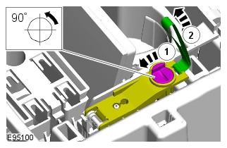


Some variation in the illustrations may occur, but the essential information is always correct.

AUTOMATIC TRANSMISSION/TRANSAXLE EXTERNAL CONTROLS - VEHICLES WITH: 8HP70 8-SPEED AUTOMATIC TRANSMISSION AWD
EMERGENCY PARK RELEASE CABLE (G2201773)
- Raise and support the vehicle on a suitable 2 post lift.
Refer to:Lifting (100-02, Description and Operation).
- Remove the engine cover.
Refer to:Engine Cover (501-05, Removal and Installation).
- Remove the left bulkhead panel.
Refer to:Secondary Bulkhead Left Panel (501-02, Removal and Installation).
- Remove the engine undershield.
Refer to:Engine Undershield (501-02, Removal and Installation).


-
NOTE:
This step requires the aid of another technician.
- Install the Emergency Park Release (EPR) cable.
- Install the 4 clips.
-
- Install and tighten the EPR cable bracket bolt.
Torque: 9Nm
- Install the wiring harness clip.
- Install and tighten the EPR cable bracket bolt.
-
- Install the cable end.
- Install and tighten the 2 bolts.
Torque: 11Nm
- Install the harness clip.
-
- Install the transmission undershield.
- Install and tighten the 10 bolts.
TorqueM10 bolts: 60NmM6 bolts: 10Nm
- Install the engine undershield.
Refer to:Engine Undershield (501-02, Removal and Installation).
- Install the left bulkhead panel.
Refer to:Secondary Bulkhead Left Panel (501-02, Removal and Installation).
- Install the engine cover.
Refer to:Engine Cover (501-05, Removal and Installation).
AUTOMATIC TRANSMISSION/TRANSAXLE EXTERNAL CONTROLS - VEHICLES WITH: 8HP70 8-SPEED AUTOMATIC TRANSMISSION AWD
TRANSMISSION CONTROL SWITCH (G1606975)
- 44.15.03
- SWITCH - SELECTOR LEVER POSITION - RENEW
- ALL DERIVATIVES
- 0.80
- USED WITHINS
GENERAL EQUIPMENT
| EQUIPMENT NAME |
|---|
| Land Rover diagnostic equipment |
- Remove the floor console upper panel.
Refer to:Floor Console Upper Section (501-12 Instrument Panel and Console, Removal and Installation).


- Install the floor console upper panel.
Refer to:Floor Console Upper Section (501-12 Instrument Panel and Console, Removal and Installation).
- Using the approved Land Rover diagnostic equipment, configure the Transmission Control Switch (TCS).
AUTOMATIC TRANSMISSION/TRANSAXLE EXTERNAL CONTROLS - VEHICLES WITH: 8HP70 8-SPEED AUTOMATIC TRANSMISSION AWD
UPSHIFT PADDLE SWITCH (G1509734)
REMOVAL AND INSTALLATION- 44.15.94
- GEARCHANGE 'UP' PADDLE SWITCH - RENEW
- ALL DERIVATIVES
- 0.10
- USED WITHINS
REMOVALNOTE:Removal steps in this procedure may contain installation details.
INSTALLATION- To install, reverse the removal procedure.
AUTOMATIC TRANSMISSION/TRANSAXLE EXTERNAL CONTROLS - VEHICLES WITH: 8HP70 8-SPEED AUTOMATIC TRANSMISSION AWD
DOWNSHIFT PADDLE SWITCH (G1509735)
REMOVAL AND INSTALLATION- 44.15.95
- GEARCHANGE 'DOWN' PADDLE SWITCH - RENEW
- ALL DERIVATIVES
- 0.10
- USED WITHINS
REMOVALNOTE:Removal steps in this procedure may contain installation details.
INSTALLATION- To install, reverse the removal procedure.
AUTOMATIC TRANSMISSION/TRANSAXLE EXTERNAL CONTROLS - VEHICLES WITH: 8HP70 8-SPEED AUTOMATIC TRANSMISSION AWD
TRANSMISSION CONTROL ACTIVATION SWITCH (G2263247)
REMOVAL AND INSTALLATION- 37.27.14
- TRANSMISSION CONTROL PARK SWITCH - RENEW
- ALL DERIVATIVES
- 0.10
- USED WITHINS
REMOVALCAUTION:Make sure that the gloves provided with the repair kit are worn throughout this procedure.
NOTES:-
This procedure contains some variation in the illustrations depending on the vehicle specification, but the essential information is always correct.
-
This procedure contains illustrations showing certain components removed to provide extra clarity.
- Disconnect the startup battery ground cable.
Refer to:Specifications (414-00 Battery and Charging System - General Information, Specifications).
INSTALLATION- Connect the startup battery ground cable.
Refer to:Specifications (414-00 Battery and Charging System - General Information, Specifications).
AUTOMATIC TRANSMISSION/TRANSAXLE EXTERNAL CONTROLS - VEHICLES WITH: 8HP70 8-SPEED AUTOMATIC TRANSMISSION AWD
TRANSMISSION CONTROL SWITCH PARK (P) BUTTON (G2398520)
REMOVAL AND INSTALLATION- 44.15.69
- TRANSMISSION CONTROL SWITCH PARK (P) BUTTON - RENEW
- ALL DERIVATIVES
- 0.10
- USED WITHINS
GENERAL EQUIPMENT
EQUIPMENT NAME Jaguar Land Rover approved diagnostic equipment REMOVALNOTE:- This procedure contains some variation in the illustrations depending on the vehicle specification, but the essential information is always correct.
- This procedure contains illustrations showing certain components removed to provide extra clarity.
INSTALLATION-
NOTE:
There is no clear audible click on installation of the Park (P) button.
- Install the new Park (P) button.
- To confirm the installation was successful, test the operation of the P button.
- Operate the P button several times to make sure the P button operates smoothly and returns to the raised position.
- Use the approved Jaguar Land Rover diagnostic equipment to read and clear any Diagnostic Trouble Codes (DTCs).