Range Rover Sport / L494 2017 FUEL CHARGING MANUAL
303-04A: Fuel Charging and Controls - TDV6 3.0L Diesel /TDV6 3.0L Diesel - Gen 1.5/TDV6 3.0L Diesel - Gen 2
303-04B: Fuel Charging and Controls - Turbocharger - TDV6 3.0L Diesel
FUEL CHARGING AND CONTROLS - TDV6 3.0L DIESEL /TDV6 3.0L DIESEL - GEN 1.5/TDV6 3.0L DIESEL - GEN 2 (G1509429)
Torque Specification
A = refer to procedure for the correct torque sequence.
| DESCRIPTION | NM | LB-FT | LB-IN |
|---|---|---|---|
| Fuel injection pump cradle bolts | 3 | - | 26 |
| Fuel injection pump retaining bolts | 23 | 16 | - |
| Fuel injection pump bracket | 10 | - | 88 |
| Fuel injection pump sprocket bolt | 50 | 37 | - |
| Fuel injection pump belt rear cover retaining bolts | 10 | - | 88 |
| Camshaft rear end accessory drive (READ) pulley hub retaining bolt | A | - | - |
| Fuel injection pump belt tensioner retaining bolt | 23 | 16 | - |
| Camshaft READ pulley retaining bolt | A | - | - |
| Fuel injector retaining bolts | 9 | - | 80 |
| Fuel rail retaining bolts | 24 | 18 | |
| High-pressure fuel line bracket retaining bolts | 10 | - | 88 |
| High-pressure fuel line union nuts | A | - | - |
| Fuel rail supply tube union nuts | A | - | - |
| Fuel crossover line union nuts | A | - | - |
| Crankcase ventilation pipe retain bolts | 10 | - | 88 |
| Intake air shutoff valve retaining nut | 10 | - | 88 |
FUEL CHARGING AND CONTROLS - TDV6 3.0L DIESEL /TDV6 3.0L DIESEL - GEN 1.5/TDV6 3.0L DIESEL - GEN 2 (G1781152)

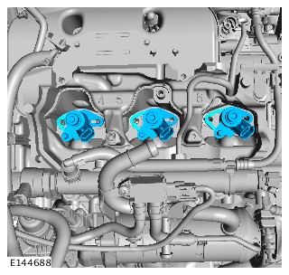
| ITEM | DESCRIPTION |
|---|---|
| 1 | Fuel Rail Pressure (FRP) sensor |
| 2 | Fuel rail - Bank 1 |
| 3 | High Pressure (HP) fuel pump - with internal transfer pump |
| 4 | Fuel rail - Bank 2 |
| 5 | Fuel rail Pressure Control Valve (PCV) |
| 6 | Fuel injector (6 off) |
The TDV6 3.0L diesel engine is equipped with a High Pressure (HP) common rail fuel injection system. With this fuel injection process, a HP fuel pump delivers a uniform level of pressure to the shared fuel lines (the fuel rails), which serve all 6 fuel injectors. Pressure is controlled to the optimum level for smooth operation.
The common rail system supports a pre and pilot injection depending on engine operating conditions, which reduces combustion noise levels, more commonly referred to as 'diesel knock'.
Fuel injection pressure is generated independently of engine speed and fuel injection events.
The fuel injection timing and volume are calculated by the Engine Control Module (ECM), which then energizes the appropriate piezo actuated injector.
The common rail fuel injection system has the following features:
- High fuel injection pressures of up to 2000 bar (29007 lbf/in²) for greater atomization of fuel (increasing performance and lowering emissions)
- Variable injection to optimize combustion in all engine operating conditions
- Low tolerances and high precision throughout the life of the system.
The system features the following components:
- HP fuel pump
- Fuel rails
- HP and Low Pressure (LP) fuel pipes
- Fuel injectors.
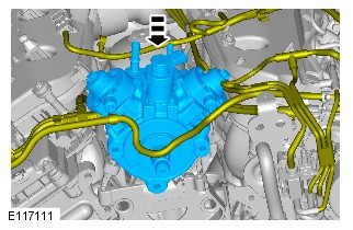
HIGH PRESSURE (HP) FUEL PUMP

| ITEM | DESCRIPTION |
|---|---|
| 1 | Low Pressure (LP) fuel return connection |
| 2 | Low Pressure (LP) fuel supply connection |
| 3 | Fuel temperature sensor |
| 4 | Drive shaft |
| 5 | Fuel outlet to Bank 2 fuel rail |
| 6 | Fuel metering valve |
| 7 | Fuel outlet to Bank 1 fuel rail |
The HP fuel pump is a 2 piston radial plunger pump. The pump has the ability to produce a maximum pressure of 2000 bar (29007 lbf/in²).
The HP fuel pump is driven from the Bank 2 cylinder head exhaust camshaft via a toothed belt. The drive from the belt rotates a cam within the pump which operates a plunger within each pumping element. A procedure and special tools are required for pump or belt replacement to time the pump. For additional information, refer to:Engine (303-01A Engine - TDV6 3.0L Diesel /TDV6 3.0L Diesel - Gen 1.5/TDV6 3.0L Diesel - Gen 2, Description and Operation) / Engine (303-01 Engine - SDV6 3.0L Diesel - Hybrid Electric Vehicle, Description and Operation) / Fuel Pump (303-04A Fuel Charging and Controls - TDV6 3.0L Diesel /TDV6 3.0L Diesel - Gen 1.5/TDV6 3.0L Diesel - Gen 2, Removal and Installation).
The HP fuel pump comprises 2 HP pumping elements, a fuel metering valve, an internal transfer pump and a fuel temperature sensor.
The fuel is delivered to the internal transfer pump via the external fuel filter and an electric fuel pump which is located in the fuel tank. For additional information, refer to:Fuel Tank and Lines (310-01A Fuel Tank and Lines - TDV6 3.0L Diesel /TDV6 3.0L Diesel - Gen 1.5/TDV6 3.0L Diesel - Gen 2, Description and Operation).
The fuel metering valve is located in the feed port between the HP pumping elements and the internal transfer pump. The fuel metering valve is a variable position solenoid-operated valve that is controlled by the ECM. The fuel metering valve determines the amount of fuel that is delivered from the internal transfer pump to the HP pumping elements. When there is no signal to the fuel metering valve, the valve is closed and there is no fuel delivery.
The fuel from the internal transfer pump is passed to the HP pumping elements at a constant pressure known as transfer pressure. The transfer pressure is controlled by an internal Pressure Relief Valve (PRV). Once the fuel enters each of the HP pumping elements the pressure rises rapidly, with each element providing a HP supply to one of the fuel rails. The pressure is controlled by the fuel rail Pressure Control Valve (PCV) and the Fuel Rail Pressure (FRP) sensor.
A controlled amount of fuel is allowed to leak-off from the internal transfer pump. This fuel cools and lubricates the internal components of the HP fuel pump, then returns to the fuel tank through the Low Pressure (LP) fuel return line.
The fuel temperature sensor is located on the rear of the HP fuel pump. It measures the fuel temperature in the LP side of the HP fuel pump. The ECM continually monitors this signal to determine the fuel temperature to prevent overheating of the fuel system. The ECM will also make fine adjustments to fuel injection quantity to adjust for fuel temperature.
FUEL RAILS

| ITEM | DESCRIPTION |
|---|---|
| 1 | Fuel rail balance pipe |
| 2 | Supply pipe to Bank 1 fuel rail |
| 3 | Supply pipe to Bank 2 fuel rail |
| 4 | Fuel rail - Bank 2 |
| 5 | Fuel Pressure Control Valve (PCV) |
| 6 | Supply pipe to fuel injector (6 off) |
| 7 | Fuel Rail Pressure (FRP) sensor |
| 8 | Fuel rail - Bank 1 |

| ITEM | DESCRIPTION |
|---|---|
| 1 | High Pressure (HP) fuel pump fuel return tube |
| 2 | Bank 2 fuel injector leak-back tube |
| 3 | Fuel rail Pressure Control Valve (PCV) fuel return tube |
| 4 | Fuel return connection to fuel cooler |
| 5 | Bank 1 fuel injector leak-back tube |
Two fuel rails are used with each rail supplying high pressure fuel to 3 fuel injectors.
Each rail has 5 threaded connections which provide for the attachment of the high pressure fuel supply from the HP fuel pump, the balance pipe and connections for the 3 injectors supplied with fuel from that rail.
The fuel pressure in the rails is detected by the FRP sensor which is located in the front of the Bank 1 fuel rail. The Bank 2 fuel rail houses a fuel rail PCV. The ECM controls the fuel rail PCV using signals from the FRP sensor. Fuel released by the fuel rail PCV flows into the LP fuel return line.
The FRP sensor is a piezo-resistive type sensor containing an actuating diaphragm. Deflection of the diaphragm provides a proportional signal (output) voltage to the ECM, dependant on the fuel pressure within the fuel rail.
Both rails are connected together with a balance pipe which ensures the pressure in both rails is equal, even though each rail is supplied from a different pumping element in the HP fuel pump.
FUEL INJECTORS

| ITEM | DESCRIPTION |
|---|---|
| 1 | Fuel return |
| 2 | O-ring seal |
| 3 | Piezo stack actuator |
| 4 | Hydraulic coupler |
| 5 | Control valve |
| 6 | Nozzle body |
| 7 | Copper sealing washer |
| 8 | Electrical connector |
| 9 | High Pressure (HP) feed |
| 10 | Nozzle |
Each injection event is controlled by a charge and discharge cycle allowing energy to dissipate in, and recover from, the injector. Never disconnect the wiring connector when the vehicle is running. The injector may remain open thus causing engine damage.
Six fuel injectors are used in the fuel system. A piezo actuator in each injector is electronically controlled by the ECM to operate the injector in response to engine speed and load conditions.
Each injector has an electrical connector which connects the injector to the engine harness. A fuel connection on the top of the injector provides for the high pressure fuel inlet from the related fuel rail. A second fuel connection allows fuel leakage within the injector to drain into the LP fuel return line.
Each injector is located in a machined hole in the cylinder head and is sealed in the cylinder head with a copper sealing washer and an O-ring seal. The injector is retained in the cylinder head with a clamp plate and 2 bolts. If an injector is removed or replaced, a new copper sealing washer and a clamp plate must be used when refitting the injector.
The injector can operate up to 5 times during one combustion cycle depending on engine speed and load. The injection sequence can occur as follows:

- Pilot injection - occurs before the main injection and improves fuel and air mixing
- Pre-injection - shortens the main injection's ignition delay and therefore reduces the generation of nitrous oxides
- Main injection - delivers the required engine torque
- After injection - occurs after the main injection and assists the re-burn of any remaining particulate matter
- Post injection - helps manage the temperature of the exhaust gas for more effective exhaust-gas after-treatment
- Injection delay 0.4 ms.
Each injector is calibrated to the ECM and applicable cylinder to which it is fitted. Therefore, if an injector is removed it must be refitted to the cylinder from which it was removed. If a new injector is fitted, a calibration routine using Land Rover approved diagnostic equipment must be performed to calibrate the injector unique code to the ECM.
The operating voltage of the injector is between 110 and 163 volts depending on engine speed and load and care must be taken when working in the vicinity of the injectors. The pressure increases linearly from 200 to 1200 bar (2900 to 17404 lbf/in²).
Each injector has an electrical resistance value of between 150 - 250 kOhms.
ENGINE STARTING
During starting, the fuel rail pressure must be at least 120 bar (1740 lbf/in²). Should the pressure be below this figure, the injectors will not operate, resulting in the vehicle not starting.
ENGINE STOPPING
To stop the engine the ECM stops energizing the actuators in the fuel injectors, therefore, no fuel is injected and the engine speed drops to zero. For additional information, refer to:Electronic Engine Controls (303-14A Electronic Engine Controls - TDV6 3.0L Diesel /TDV6 3.0L Diesel - Gen 1.5/TDV6 3.0L Diesel - Gen 2, Description and Operation) / Electronic Engine Controls (303-14 Electronic Engine Controls - SDV6 3.0L Diesel - Hybrid Electric Vehicle, Description and Operation).
HP FUEL PUMP
When the HP fuel pump is rotated, pressure is created when the fuel metering valve is open and the fuel rail PCV is closed. Both valves are electronically controlled by the ECM to allow variable fuel delivery and pressure control. When the ECM actuates the fuel injectors, the fuel rail pressure drop is off-set by additional fuel being delivered to the fuel rails by the fuel rail PCV. The fuel pressure in the system is reduced within a few seconds after the engine has stopped as the fuel rail PCV no longer has the holding current it requires, and therefore opens. No residual pressure remains in the system and the fuel is released into the LP fuel return line through the open fuel rail PCV.
A = Hardwired.
| ITEM | DESCRIPTION |
|---|---|
| 1 | Battery |
| 2 | Battery Junction Box 2 (BJB2) |
| 3 | Battery Junction Box (BJB) |
| 4 | Auxiliary Junction Box (AJB) |
| 5 | Engine Junction Box (EJB) |
| 6 | Central Junction Box (CJB) |
| 7 | Engine Control Module (ECM) |
| 8 | Fuel injector (6 off) |
| 9 | Fuel temperature sensor |
| 10 | Fuel metering valve |
| 11 | Fuel Rail Pressure (FRP) sensor |
| 12 | Fuel rail Pressure Control Valve (PCV) |
Diagnosis and Testing
FUEL CHARGING AND CONTROLS - TDV6 3.0L DIESEL /TDV6 3.0L DIESEL - GEN 1.5/TDV6 3.0L DIESEL - GEN 2 (G2718609)
For a detailed description of the fuel charging and controls system and operation, refer to the relevant Description and Operation section of the workshop manual. REFER to:Fuel Charging and Controls (303-04A Fuel Charging and Controls - TDV6 3.0L Diesel /TDV6 3.0L Diesel - Gen 1.5/TDV6 3.0L Diesel - Gen 2, Description and Operation).
Make sure that all suitable safety precautions are observed when carrying out any work on the fuel system. Failure to observe this warning may result in personal injury.
-
Make sure that absolute cleanliness is observed when working with these components. Always install blanking plugs to any open orifices or lines. Failure to follow this instruction may result in damage to the vehicle.
-
Diagnosis by substitution from a donor vehicle is NOT acceptable. Substitution of control modules does not guarantee confirmation of a fault and may also cause additional faults in the vehicle being checked and/or the donor vehicle.
Check and rectify basic faults before beginning diagnostic routines involving pinpoint tests.
- Verify the customer concern.
- Visually inspect for obvious signs of mechanical or electrical damage.
Visual Inspection
| MECHANICAL | ELECTRICAL |
|---|---|
|
|
- If an obvious cause for an observed or reported concern is found, correct the cause (if possible) before proceeding to the next step.
- If the cause is not visually evident, verify the symptom and refer to the Symptom Chart, alternatively check for Diagnostic Trouble Code(s) (DTC)s and refer to the DTC Index.
| SYMPTOM | POSSIBLE CAUSES | ACTION |
|---|---|---|
| Engine cranks, but does not start |
|
Check that the inertia switch has not tripped. Check the fuel level and condition. Draw off approximately 1 ltr (2.11 pints) of fuel and allow to stand for 1 minute. Check to make sure there is no separation of the fuel indicating water or other liquid in the fuel. Check the intake air system for leaks. Check the fuel pump operation, check the low-pressure fuel system for leaks/damage. Check the fuel filter, check for DTCs indicating a fuel volume or pressure control valve fault. Check the fuel pump. Check the CKP circuits. Refer to the electrical guides. |
| Difficult to start |
|
Check the glow plug circuits. Refer to the electrical guides. Check the fuel level/condition. Draw off approximately 1 ltr (2.11 pints) of fuel and allow to stand for 1 minute. Check to make sure there is no separation of the fuel indicating water or other liquid in the fuel. Check the intake air system for leaks. Check the fuel pump operation, check the low-pressure fuel system for leaks/damage. Check the fuel filter, check for DTCs indicating a fuel volume or pressure control valve fault. Check the exhaust gas recirculation system. |
| Rough idle |
|
Check the intake air system for leaks. Check the fuel level/condition. Draw off approximately 1 ltr (2.11 pints) of fuel and allow to stand for 1 minute. Check to make sure there is no separation of the fuel indicating water or other liquid in the fuel. Check the low-pressure fuel system for leaks/damage. Check the fuel filter, check for DTCs indicating a fuel volume or pressure control valve fault. Check the exhaust gas recirculation system. |
| Lack of power when accelerating |
|
Check the intake air system for leakage or restriction. Check for a blockage/restriction in the exhaust system, install new components as necessary. Check for DTCs indicating a fuel pressure fault. Check the exhaust gas recirculation system. Check turbocharger actuator. |
| Engine stops/stalls |
|
Check the intake air system for leaks. Check the fuel level/condition. Draw off approximately 1 ltr (2.11 pints) of fuel and allow to stand for 1 minute. Check to make sure there is no separation of the fuel indicating water or other liquid in the fuel. Check the fuel system for leaks/damage: Check for DTCs indicating a fuel volume or pressure control valve fault. Check the exhaust gas recirculation system. |
| Engine judders |
|
Check the fuel level/condition. Draw off approximately 1 ltr (2.11 pints) of fuel and allow to stand for 1 minute. Check to make sure there is no separation of the fuel indicating water or other liquid in the fuel. Check the intake air system for leaks. Check the low-pressure fuel system for leaks/damage. Check the high pressure fuel system for leaks, check for DTCs indicating a fuel volume or pressure control valve fault. Check the fuel pump. |
| Excessive fuel consumption |
|
Check the low-pressure fuel system for leaks/damage. Check for DTCs indicating a fuel volume or pressure control valve fault. Check the fuel temperature sensor, fuel pump, etc for leaks. Check for injector DTCs. Check the exhaust gas recirculation system. |
Affected Vehicle Range
| MODEL: | MODEL YEAR: | VEHICLE IDENTIFICATION NUMBER (VIN): | ASSEMBLY PLANT: | APPLICABILITY: |
|---|---|---|---|---|
| Range Rover (LG) | 2015-2019 | 214632-533162 | Solihull | TDV6 3.0L Diesel - Gen 2 |
| Range Rover Sport (LW) | 2015-2016 | 518538-599999 | Solihull | TDV6 3.0L Diesel - Gen 2 |
| Range Rover Sport (LW) | 2015-2018 | 613794-699492 | Solihull | TDV6 3.0L Diesel - Gen 2 |
| Range Rover Sport (LW) | 2016-2018 | 100003-199996 | Solihull | TDV6 3.0L Diesel - Gen 2 |
| Range Rover Sport (LW) | 2018-2019 | 400291-421768 | Solihull | TDV6 3.0L Diesel - Gen 2 |
| Range Rover Sport (LW) | 2018-2019 | 800063-831586 | Solihull | TDV6 3.0L Diesel - Gen 2 |
| Range Rover Velar (LY) | 2018-2019 | 700002-799787 | Solihull | TDV6 3.0L Diesel |
| Discovery (LR) | 2017-2019 | 000001-090164 | Solihull | TDV6 3.0L Diesel |
The MIL is illuminated on the IPC with DTC P0234-77 stored in the Powertrain Control Module (PCM) which may be accompanied with DTCs P2463-00 and P246B-00.
Component failure.
Follow the instructions below.
| DESCRIPTION | QUANTITY |
|---|---|
| Intake air shutoff throttle | 1 |
| Inlet hose clamp | 1 |
16 Model Year (MY) vehicles and earlier
This procedure requires a minimum of SDD 158.04 and Software Management Pack 329 loaded or later.
-
The JLR approved diagnostic equipment will read the VIN for the vehicle and automatically take the vehicle out of ‘Transportation mode’ if required.
-
All ignition ON/OFF instructions must be followed. Failure to complete these instructions may cause damage to the vehicle control modules.
- Connect the JLR approved battery support unit.
- Connect the JLR approved diagnostic equipment to the vehicle and begin a new session.
- Follow the JLR approved diagnostic equipment prompts.
- Using the JLR approved diagnostic equipment read the DTCs.
- If DTC P0234-77 is stored, continue to the 'Service Instruction A'.
- If DTC P0234-77 is not stored, do not continue with this procedure, continue diagnosis of the concern (see TOPIx Workshop Manual section 100-00: General Information - Description and Operation).
- When all of the tasks are complete, exit the session.
17 Model Year (MY) vehicles and later
This procedure requires Pathfinder version 259 loaded or a later version.
-
The JLR approved diagnostic equipment will read the VIN for the vehicle and automatically take the vehicle out of ‘Transportation mode’ if required.
-
All ignition ON/OFF instructions must be followed. Failure to complete these instructions may cause damage to the vehicle control modules.
- Connect the JLR approved battery support unit.
- Connect the JLR approved diagnostic equipment to the vehicle and begin a new diagnostic session.
- Follow the JLR approved diagnostic equipment prompts.
- Select 'ECU Diagnostics'.
- Select 'All DTCs'.
- If DTC P0234-77 is stored, continue to the 'Service Instruction A'.
- If DTC P0234-77 is not stored, do not continue with this procedure, continue diagnosis of the concern (see TOPIx Workshop Manual section 100-00: General Information - Description and Operation).
- When all of the tasks are complete, exit the session.
The DTC P0234-77 can be attributed to a leak in the air intake system.
- Complete a leakage test on the intake system using smoke test equipment (see TOPIx Workshop Manual section 303-12: Engine system general information - General procedures - Leakage test using smoke test equipment).
- If any leaks are found, repair as required referring to TOPIx Workshop Manual and submit a separate warranty claim.
- If no leaks are found, continue to 'Service Instruction B'.
- If any leaks have been rectified complete DTC read and clear, continue to step 4 for 16 MY vehicles and earlier or step 13 for 17 MY vehicles and later.
16 Model Year (MY) vehicles and earlier
This procedure requires a minimum of SDD 158.04 and Software Management Pack 329 loaded or later.
-
The JLR approved diagnostic equipment will read the VIN for the vehicle and automatically take the vehicle out of ‘Transportation mode’ if required.
-
All ignition ON/OFF instructions must be followed. Failure to complete these instructions may cause damage to the vehicle control modules.
- Connect the JLR approved battery support unit.
- Connect the JLR approved diagnostic equipment to the vehicle and begin a new session.
- Follow the JLR approved diagnostic equipment prompts.
- Using the JLR approved diagnostic equipment clear the DTCs.
- Complete a short vehicle road test.
- Using the JLR approved diagnostic equipment read the DTCs.
- If DTC P0234-77 is stored, continue to 'Service Instruction B'.
- If DTC P0234-77 is no longer stored, complete a dynamic regeneration using the diagnostic procedures below.
- If required, reset the vehicle to ‘Transportation mode’.
- When all of the tasks are complete, exit the session.
- Disconnect the JLR approved diagnostic equipment and the JLR approved battery support unit.
17 Model Year (MY) vehicles and later
This procedure requires Pathfinder version 259 loaded or a later version.
-
The JLR approved diagnostic equipment will read the VIN for the vehicle and automatically take the vehicle out of ‘Transportation Mode’ if required.
-
All ignition ON/OFF instructions must be followed. Failure to complete these instructions may cause damage to the vehicle control modules.
- Connect the JLR approved battery support unit.
- Connect the JLR approved diagnostic equipment to the vehicle and begin a new diagnostic session.
- Follow the JLR approved diagnostic equipment prompts.
- Select 'ECU Diagnostics'.
- Select 'All DTCs'.
- Select 'Clear all DTCs'.
- Complete a short vehicle road test.
- Select 'ECU Diagnostics'.
- Select 'All DTCs'.
- If DTC P0234-77 is stored, continue to the 'Service Instruction B'.
- If DTC P0234-77 is no longer stored, complete a dynamic regeneration using the diagnostic procedures below.
- Follow all on-screen instructions to complete this task.
- When all of the tasks are complete, exit the current session.
- Disconnect the JLR approved diagnostic equipment and the Jaguar Land Rover approved battery support unit.
Vehicles affected by this procedure are equipped with the Low Pressure (LP) Exhaust Gas Recirculation (EGR) system.
- Renew the intake air shutoff throttle (see TOPIx Workshop Manual section 303-04: Fuel Charging and Controls - Removal and Installation - Intake Air Shutoff Throttle).
- After installing a new intake air shut off throttle complete routine - Initialise Throttle Valve Actuator Learning 0x4030
- Complete a dynamic regeneration using the diagnostic procedures below.
16 Model Year (MY) vehicles and earlier
This procedure requires a minimum of SDD 158.04 and Software Management Pack 329 loaded or later.
-
The JLR approved diagnostic equipment will read the VIN for the vehicle and automatically take the vehicle out of ‘Transportation mode’ if required.
-
All ignition ON/OFF instructions must be followed. Failure to complete these instructions may cause damage to the vehicle control modules.
- Connect the JLR approved battery support unit.
- Connect the JLR approved battery support unit.
- Connect the JLR approved diagnostic equipment to the vehicle and begin a new session.
- Follow the JLR approved diagnostic equipment prompts.
- Click here to run: Diesel particulate filter dynamic regeneration (158.04 / 73670)
- If the hyperlink is not available, the application can be found as follows:
- Select the 'Service Functions’ Session Type
- Run 'Diesel particulate filter dynamic regeneration'
- If required, reset the vehicle to ‘Transportation mode’.
- When all of the tasks are complete, exit the session.
- Disconnect the JLR approved diagnostic equipment and the JLR approved battery support unit.
17 Model Year (MY) vehicles and later
This procedure requires Pathfinder version 259 loaded or a later version.
-
The JLR approved diagnostic equipment will read the VIN for the vehicle and automatically take the vehicle out of ‘Transportation mode’ if required.
-
All ignition ON/OFF instructions must be followed. Failure to complete these instructions may cause damage to the vehicle control modules.
- Connect the JLR approved battery support unit.
- Connect the JLR approved diagnostic equipment to the vehicle and begin a new diagnostic session.
- Follow the JLR approved diagnostic equipment prompts.
- Select 'Service'.
- Select 'Powertrain Control Module [PCM]: Diesel particulate filter dynamic regeneration'.
- Follow all on screen instructions to complete this task.
- If required, reset the vehicle to ‘Transportation mode’.
- When the task is completed, exit the session.
- Disconnect the JLR approved diagnostic equipment and the JLR approved battery support unit.
For a list of Diagnostic Trouble Codes that could be set on this vehicle, please refer to Section 100-00. REFER to:Diagnostic Trouble Code Index - TDV6 3.0L Diesel /TDV6 3.0L Diesel - Gen 1.5/TDV6 3.0L Diesel - Gen 2, DTC: Powertrain Control Module B10A2-07 to P02D7-32 (100-00 General Information, Description and Operation).
General ProceduresFUEL CHARGING AND CONTROLS - TDV6 3.0L DIESEL /TDV6 3.0L DIESEL - GEN 1.5/TDV6 3.0L DIESEL - GEN 2
FUEL INJECTION COMPONENT CLEANING (G871913)
- 19.50.22
- FUEL INJECTION COMPONENT CLEANING USING A VACUUM GUN
- 3000 CC, TDV6
- 0.10
- USED WITHINS
-
Do not carry out any repairs to the fuel system with the engine running. The fuel pressure within the system can be as high as 1700 bar (24,656 lb-sq-in). Failure to follow this instruction may result in personal injury.
-
Do not smoke or carry lighted tobacco or open flame of any type when working on or near any fuel related components. Highly flammable vapors are always present and may ignite. Failure to follow these instructions may result in personal injury.
-
If fuel contacts the eyes, flush the eyes with cold water or eyewash solution and seek immediate medical attention.
-
Place the vehicle in a well ventilated, quarantined area and arrange ' No Smoking/Petrol Fumes' signs about the vehicle.
-
Wait at least 30 seconds after the engine stops before commencing any repair to the high-pressure fuel injection system. Failure to follow this instruction may result in personal injury.
-
Wash hands thoroughly after fuel handling, as prolonged contact may cause irritation. Should irritation develop, seek medical attention.
-
Do not carry or operate cellular phones when working on or near any fuel related components. Highly flammable vapors are always present and may ignite. Failure to follow these instructions may result in personal injury.
-
Before using the cleaning fluid, protect all electrical components and connectors with lint-free non-flocking material.
-
Make sure that all parts removed from the vehicle are placed on the lint-free non-flocking material.
-
Make sure that any protective clothing worn is clean and made from lint-free non-flocking material.
-
Make sure that clean non-plated tools are used. Clean tools using a new brush that will not lose its bristles and fresh cleaning fluid, prior to starting work on the vehicle.
-
Use a steel topped workbench and cover it with clean, lint-free non-flocking material.
-
Make sure the workshop area in which the vehicle is being worked on is as clean and as dust free as possible. Foreign matter from work on clutches, brakes or from machining or welding operations can contaminate the fuel system and may result in later malfunction.
Pneumatic vacuum gun
- Using a new brush that will not lose its bristles, brush cleaning fluid onto the components being removed and onto the surrounding area.
- Using a pneumatic vacuum gun, remove all traces of cleaning fluid and foreign material.
- Dispose of any used cleaning fluid and the brush after completing the repair.
Removal and Installation
UEL CHARGING AND CONTROLS - TDV6 3.0L DIESEL /TDV6 3.0L DIESEL - GEN 1.5/TDV6 3.0L DIESEL - GEN 2
LEFT FUEL INJECTORS (G1509431)
- 19.60.09
- INJECTORS - LH BANK SET - RENEW
- 3000 CC, TDV6
- 2.20
- USED WITHINS
SPECIAL TOOL(S)

100-012
Slide Hammer

310-213
Fuel Injector Removal Adapter
PART(S)
| STEP | PART NAME | QUANTITY |
|---|---|---|
| Installation Step 2 | Fuel injector seals | 1 |
| Installation Step 2 | Fuel injector washer(s) | 1 |
| Installation Step 5 | Fuel injector high pressure pipe(s) | 1 |
Diesel fuel injection equipment is manufactured to very precise tolerances and fine clearances. It is therefore essential that absolute cleanliness is observed when working with these components. Always install new blanking plugs to any open orifices or lines. Failure to follow this instruction may result in foreign matter ingress to the fuel injection system.
-
Some variation in the illustrations may occur, but the essential information is always correct.
-
Refurbished fuel injector leak off connector color does not denote the fuel injector flow characteristics. Only the refurbished part number is to be used to identify the type of injector.
-
Refer to:Fuel Injection Component Cleaning (303-04E Fuel Charging and Controls - TDV8 4.4L Diesel, General Procedures).
-
Refer to:Specifications (414-00 Battery and Charging System - General Information, Specifications).
-
Refer to:Secondary Bulkhead Center Panel - TDV6 3.0L Diesel /TDV6 3.0L Diesel - Gen 1.5/TDV6 3.0L Diesel - Gen 2 (501-02 Front End Body Panels, Removal and Installation).
-
Refer to:Cooling System Partial Draining and Vacuum Filling (303-03A Engine Cooling - TDV6 3.0L Diesel /TDV6 3.0L Diesel - Gen 1.5/TDV6 3.0L Diesel - Gen 2, General Procedures).


-
Refer to:Cooling System Partial Draining and Vacuum Filling (303-03A Engine Cooling - TDV6 3.0L Diesel /TDV6 3.0L Diesel - Gen 1.5/TDV6 3.0L Diesel - Gen 2, General Procedures).
-
Refer to:Secondary Bulkhead Center Panel - TDV6 3.0L Diesel /TDV6 3.0L Diesel - Gen 1.5/TDV6 3.0L Diesel - Gen 2 (501-02 Front End Body Panels, Removal and Installation).
-
Refer to:Specifications (414-00 Battery and Charging System - General Information, Specifications).
- If a new unit is installed, configure using the approved diagnostic tool.
FUEL CHARGING AND CONTROLS - TDV6 3.0L DIESEL /TDV6 3.0L DIESEL - GEN 1.5/TDV6 3.0L DIESEL - GEN 2
RIGHT FUEL INJECTORS (G1509432)
- 19.60.11
- INJECTORS - RH BANK SET - RENEW
- 3000 CC, TDV6
- 2.20
- USED WITHINS
SPECIAL TOOL(S)
100-012
Slide Hammer
310-213
Fuel Injector Removal Adapter

JLR-310-237
Remover, Fuel Injector
PART(S)
| STEP | PART NAME | QUANTITY |
|---|---|---|
| Installation Step 2 | Fuel injector seals | 1 |
| Installation Step 2 | Fuel injector washer(s) | 1 |
| Installation Step 5 | Fuel injector high pressure pipe(s) | 1 |
Diesel fuel injection equipment is manufactured to very precise tolerances and fine clearances. It is therefore essential that absolute cleanliness is observed when working with these components. Always install new blanking plugs to any open orifices or lines. Failure to follow this instruction may result in foreign matter ingress to the fuel injection system.
-
Some variation in the illustrations may occur, but the essential information is always correct.
-
Refurbished fuel injector leak off connector color does not denote the fuel injector flow characteristics. Only the refurbished part number is to be used to identify the type of injector.
-
Refer to:Fuel Injection Component Cleaning (303-04E Fuel Charging and Controls - TDV8 4.4L Diesel, General Procedures).
-
Refer to:Specifications (414-00 Battery and Charging System - General Information, Specifications).
-
Refer to:Secondary Bulkhead Center Panel - TDV6 3.0L Diesel /TDV6 3.0L Diesel - Gen 1.5/TDV6 3.0L Diesel - Gen 2 (501-02 Front End Body Panels, Removal and Installation).
-
Refer to:Cooling System Partial Draining and Vacuum Filling (303-03F Engine Cooling - TDV8 4.4L Diesel, General Procedures).

-
CAUTIONS:
-
Be prepared to collect escaping fuel.
-
Before disconnecting or removing components, ensure the area around the joint faces and connections are clean. Plug open connections to prevent contamination.
-
LH illustration shown, RH is similar.
NOTE:Make sure that the fuel injector return line has a maximum of 8 uses.
-


-
Refer to:Cooling System Partial Draining and Vacuum Filling (303-03F Engine Cooling - TDV8 4.4L Diesel, General Procedures).
-
Refer to:Secondary Bulkhead Center Panel - TDV6 3.0L Diesel /TDV6 3.0L Diesel - Gen 1.5/TDV6 3.0L Diesel - Gen 2 (501-02 Front End Body Panels, Removal and Installation).
-
Refer to:Specifications (414-00 Battery and Charging System - General Information, Specifications).
- If a new unit is installed, configure using the approved diagnostic tool.
FUEL CHARGING AND CONTROLS - TDV6 3.0L DIESEL /TDV6 3.0L DIESEL - GEN 1.5/TDV6 3.0L DIESEL - GEN 2
FUEL PUMP (G1509433)
- 19.45.08
- FUEL PUMP - RENEW
- 3000 CC, TDV6
- 6.70
- USED WITHINS
SPECIAL TOOL(S)

303-1145/2
Remover, Camshaft Rear Pulley Bolt

310-138A
Holding Tool, Fuel Pump Pulley

310-139A
Holding Tool, Fuel Pump Pulley

JLR-303-1523
Remover/Installer, Camshaft Rear Pulley
PART(S)
| STEP | PART NAME | QUANTITY |
|---|---|---|
| Installation Step 6 | Camshaft sprocket bolt | 1 |
| Installation Step 16 | Left fuel rail supply pipe | 1 |
| Installation Step 16 | Right fuel rail supply pipe | 1 |
| Installation Step 19 | Fuel rail balance pipe | 1 |
| Installation Step 20 | Fuel rail supply pipe(s) | 1 |
-
Removal steps in this procedure may contain installation details.
-
Some variation in the illustrations may occur, but the essential information is always correct.
-
Refer to:Fuel Injection Component Cleaning (303-04E Fuel Charging and Controls - TDV8 4.4L Diesel, General Procedures).
-
Refer to:Rear End Accessory Drive (303-05A Accessory Drive - TDV6 3.0L Diesel /TDV6 3.0L Diesel - Gen 1.5/TDV6 3.0L Diesel - Gen 2, Removal and Installation).
-
Refer to:Crankcase Vent Oil Separator (303-08A Engine Emission Control - TDV6 3.0L Diesel /TDV6 3.0L Diesel - Gen 1.5/TDV6 3.0L Diesel - Gen 2, Removal and Installation).


-
CAUTION:
Failure to use special tool JLR-303-1523 might result in engine damage/failure.
Special Tool(s): JLR-303-1523

-
Special Tool(s): JLR-303-1523

-
Using the special tool, remove and discard the rear camshaft pulley retaining bolt.Special Tool(s): 303-1145/2

- Remove the special tools.


-
Special Tool(s): 310-139A

-
Special Tool(s): 310-138A

-
Special Tool(s): 310-139ATorque: 50Nm

-
Special Tool(s): JLR-303-1523Torque: 10Nm
-
Special Tool(s): JLR-303-1523
-
CAUTION:
Make sure the torque wrench setting procedure is followed correctly. Failure to follow this instruction may result in damage to the vehicle.
- Calculate the setting for the torque wrench:
- Stage 1: Multiply the required torque by the effective length of the torque wrench (1).
- Stage 2: Add the effective length of the special tool (2) to the effective length of the torque wrench.
- Stage 3: Divide the total of stage 1 by the total of stage 2.
- Stage 4: Set the torque wrench to the figure arrived at in stage 3.

-
CAUTION:
Make sure the torque wrench setting procedure is followed correctly. Failure to follow this instruction may result in damage to the vehicle.
- Using the special tool, install the camshaft rear pulley retaining bolt.
- Stage one: Tighten to 80 Nm (59 lb.ft).
- Stage two: Tighten a further 80 degrees.
- Remove the special tools.


-
Refer to:Crankcase Vent Oil Separator (303-08A Engine Emission Control - TDV6 3.0L Diesel /TDV6 3.0L Diesel - Gen 1.5/TDV6 3.0L Diesel - Gen 2, Removal and Installation).
-
Refer to:Rear End Accessory Drive (303-05A Accessory Drive - TDV6 3.0L Diesel /TDV6 3.0L Diesel - Gen 1.5/TDV6 3.0L Diesel - Gen 2, Removal and Installation).
-
Refer to:High-Pressure Fuel System Bleeding (310-00 Fuel System - General Information, General Procedures).
FUEL CHARGING AND CONTROLS - TDV6 3.0L DIESEL /TDV6 3.0L DIESEL - GEN 1.5/TDV6 3.0L DIESEL - GEN 2
LEFT FUEL RAIL (G2165648)
- 19.60.03
- FUEL RAIL - LH BANK - RENEW
- 3000 CC, TDV6
- 3.20
- USED WITHINS
PART(S)
| STEP | PART NAME | QUANTITY |
|---|---|---|
| Installation Step 1 | Fuel rail balance pipe | 1 |
| Installation Step 6 | Left fuel rail supply pipe | 1 |
| Installation Step 11 | Fuel injector high pressure pipe(s) | 3 |
Wait for a minimum of 1 minute after the engine has stopped before carrying out any repair to the fuel injection system.
Before disconnecting or removing components, ensure the area around the joint faces and connections are clean. Plug open connections to prevent contamination.
Some variation in the illustrations may occur, but the essential information is always correct.
- Disconnect the startup battery ground cable.
Refer to:Battery and Cables (414-01 Battery, Mounting and Cables, Description and Operation).
-
Refer to:Secondary Bulkhead Center Panel - TDV6 3.0L Diesel /TDV6 3.0L Diesel - Gen 1.5/TDV6 3.0L Diesel - Gen 2 (501-02 Front End Body Panels, Removal and Installation).
-
Refer to:Cooling System Draining and Vacuum Filling (303-03A Engine Cooling - TDV6 3.0L Diesel /TDV6 3.0L Diesel - Gen 1.5/TDV6 3.0L Diesel - Gen 2, General Procedures).
-
NOTE:
This step is only required on vehicles fitted with twin turbochargers.
Refer to:Left Exhaust Gas Recirculation Valve Outlet Tube - TDV6 3.0L Diesel - Gen 1.5 (303-08A Engine Emission Control - TDV6 3.0L Diesel /TDV6 3.0L Diesel - Gen 1.5/TDV6 3.0L Diesel - Gen 2, Removal and Installation).
-
Refer to:Left Exhaust Gas Recirculation Valve - TDV6 3.0L Diesel - Gen 2 (303-08A Engine Emission Control - TDV6 3.0L Diesel /TDV6 3.0L Diesel - Gen 1.5/TDV6 3.0L Diesel - Gen 2, Removal and Installation).
-
Refer to:Fuel Injection Component Cleaning (303-04A Fuel Charging and Controls - TDV6 3.0L Diesel /TDV6 3.0L Diesel - Gen 1.5/TDV6 3.0L Diesel - Gen 2, General Procedures).


-
Refer to:Left Exhaust Gas Recirculation Valve - TDV6 3.0L Diesel - Gen 2 (303-08A Engine Emission Control - TDV6 3.0L Diesel /TDV6 3.0L Diesel - Gen 1.5/TDV6 3.0L Diesel - Gen 2, Removal and Installation).
-
NOTE:
This step is only required on vehicles fitted with twin turbochargers.
Refer to:Left Exhaust Gas Recirculation Valve Outlet Tube - TDV6 3.0L Diesel - Gen 1.5 (303-08A Engine Emission Control - TDV6 3.0L Diesel /TDV6 3.0L Diesel - Gen 1.5/TDV6 3.0L Diesel - Gen 2, Removal and Installation).
-
Refer to:Cooling System Draining and Vacuum Filling (303-03A Engine Cooling - TDV6 3.0L Diesel /TDV6 3.0L Diesel - Gen 1.5/TDV6 3.0L Diesel - Gen 2, General Procedures).
-
Refer to:Secondary Bulkhead Center Panel - TDV6 3.0L Diesel /TDV6 3.0L Diesel - Gen 1.5/TDV6 3.0L Diesel - Gen 2 (501-02 Front End Body Panels, Removal and Installation).
- Connect the startup battery ground cable.
FUEL CHARGING AND CONTROLS - TDV6 3.0L DIESEL /TDV6 3.0L DIESEL - GEN 1.5/TDV6 3.0L DIESEL - GEN 2
RIGHT FUEL RAIL (G1509435)
- 19.60.05
- FUEL RAIL - RH BANK - RENEW
- 3000 CC, TDV6
- 2.90
- USED WITHINS
PART(S)
| STEP | PART NAME | QUANTITY |
|---|---|---|
| Installation Step 1 | Right fuel rail supply pipe | 1 |
| Installation Step 2 | Fuel rail balance pipe | 1 |
| Installation Step 10 | Fuel injector high pressure pipe(s) | 1 |
Some variation in the illustrations may occur, but the essential information is always correct.
-
Refer to:Specifications (414-00 Battery and Charging System - General Information, Specifications).
-
Refer to:Secondary Bulkhead Center Panel - TDV6 3.0L Diesel /TDV6 3.0L Diesel - Gen 1.5/TDV6 3.0L Diesel - Gen 2 (501-02 Front End Body Panels, Removal and Installation).
-
Refer to:Cooling System Partial Draining and Vacuum Filling (303-03F Engine Cooling - TDV8 4.4L Diesel, General Procedures).
-
Refer to:Left Exhaust Gas Recirculation Valve Outlet Tube - TDV6 3.0L Diesel - Gen 1.5 (303-08A Engine Emission Control - TDV6 3.0L Diesel /TDV6 3.0L Diesel - Gen 1.5/TDV6 3.0L Diesel - Gen 2, Removal and Installation).
-
Refer to:Fuel Injection Component Cleaning (303-04E Fuel Charging and Controls - TDV8 4.4L Diesel, General Procedures).


-
Refer to:Right Exhaust Gas Recirculation Valve Outlet Tube (303-08A Engine Emission Control - TDV6 3.0L Diesel /TDV6 3.0L Diesel - Gen 1.5/TDV6 3.0L Diesel - Gen 2, Removal and Installation).
-
Refer to:Cooling System Partial Draining and Vacuum Filling (303-03F Engine Cooling - TDV8 4.4L Diesel, General Procedures).
-
Refer to:Secondary Bulkhead Center Panel - TDV6 3.0L Diesel /TDV6 3.0L Diesel - Gen 1.5/TDV6 3.0L Diesel - Gen 2 (501-02 Front End Body Panels, Removal and Installation).
-
Refer to:Specifications (414-00 Battery and Charging System - General Information, Specifications).
FUEL CHARGING AND CONTROLS - TDV6 3.0L DIESEL /TDV6 3.0L DIESEL - GEN 1.5/TDV6 3.0L DIESEL - GEN 2
INTAKE AIR SHUTOFF THROTTLE (G1509436)
- 19.70.32
- THROTTLE - INTAKE AIR SHUT OFF - RENEW
- 3000 CC, TDV6
- 0.20
- USED WITHINS
PART(S)
| STEP | PART NAME | QUANTITY |
|---|---|---|
| Removal Step 8 | Exhaust gas recirculation outlet pipe to throttle body clamp | 1 |
| Removal Step 12 | Intake air shutoff throttle seals | 3 |
Removal steps in this procedure may contain installation details.
-
Refer to:Engine Cover - TDV6 3.0L Diesel /TDV6 3.0L Diesel - Gen 1.5/TDV6 3.0L Diesel - Gen 2 (501-05 Interior Trim and Ornamentation, Removal and Installation).


-
NOTE:
If equipped.
Refer to:Left Exhaust Gas Recirculation Valve Outlet Tube - TDV6 3.0L Diesel - Gen 1.5 (303-08A Engine Emission Control - TDV6 3.0L Diesel /TDV6 3.0L Diesel - Gen 1.5/TDV6 3.0L Diesel - Gen 2, Removal and Installation).


- To install, reverse the removal procedure.
- If a new unit is installed, configure using the approved diagnostic tool.
FUEL CHARGING AND CONTROLS - TDV6 3.0L DIESEL /TDV6 3.0L DIESEL - GEN 1.5/TDV6 3.0L DIESEL - GEN 2
HIGH PRESSURE FUEL PUMP TEMPERATURE SENSOR (G2225219)
- 19.45.37
- HIGH PRESSURE FUEL PUMP TEMPERATURE SENSOR - RENEW
- 3000 CC, TDV6
- 6.70
- USED WITHINS
-
This procedure contains illustrations showing certain components removed to provide extra clarity.
-
This procedure contains some variation in the illustrations depending on the vehicle specification, but the essential information is always correct.
- Raise and support the vehicle on 2 post lift.
Refer to:Lifting (100-02 Jacking and Lifting, Description and Operation).
- Remove the High Pressure (HP) fuel pump.
Refer to:Fuel Pump (303-04A Fuel Charging and Controls - TDV6 3.0L Diesel /TDV6 3.0L Diesel - Gen 1.5/TDV6 3.0L Diesel - Gen 2, Removal and Installation).

- Install the HP fuel pump.
Refer to:Fuel Pump (303-04A Fuel Charging and Controls - TDV6 3.0L Diesel /TDV6 3.0L Diesel - Gen 1.5/TDV6 3.0L Diesel - Gen 2, Removal and Installation).
FUEL CHARGING AND CONTROLS - TDV6 3.0L DIESEL /TDV6 3.0L DIESEL - GEN 1.5/TDV6 3.0L DIESEL - GEN 2
FUEL PUMP DRIVER MODULE (G1605355)
- 19.45.11
- MODULE - FUEL PUMP CONTROL - RENEW
- ALL DERIVATIVES
- 0.20
- USED WITHINS
Removal steps in this procedure may contain installation details.


-
To install, reverse the removal procedure.NOTE:
If a new component has been installed, configure using Land Rover approved diagnostic equipment.
303-04B: Fuel Charging and Controls - Turbocharger - TDV6 3.0L Diesel
FUEL CHARGING AND CONTROLS - TURBOCHARGER - TDV6 3.0L DIESEL (G1509437)
Torque Specification
| DESCRIPTION | NM | LB-FT | LB-IN |
|---|---|---|---|
| Exhaust manifold retaining nuts | 28 | 21 | - |
| Turbocharger oil return tube to turbocharger retaining bolt | 9 | - | 80 |
| Turbocharger oil return tube to engine retaining bolt | 9 | - | 80 |
| Turbocharger bracket retaining bolts | 32 | 24 | - |
| Turbocharger to exhaust manifold retaining nuts | 24 | 18 | - |
| Exhaust manifold heatshield retaining bolt | 11 | 8 | - |
| Exhaust heatshield retaining bolt | 9 | - | 80 |
| Turbocharger oil supply tube union bolt | 30 | 22 | - |
| Exhaust gas recirculation (EGR) tube to EGR valve retaining bolts | 10 | - | 88 |
| EGR valve tube to exhaust manifold retaining bolts | 10 | - | 88 |
| Turbocharger bypass valve retaining bolts | 9 | 80 | |
| Turbocharger bypass valve to cross section duct bolts | 10 | 88 |
FUEL CHARGING AND CONTROLS - TURBOCHARGER - TDV6 3.0L DIESEL
TURBOCHARGER (G1868446)

| ITEM | DESCRIPTION |
|---|---|
| 1 | Variable Geometry Turbine (VGT) turbocharger |

| ITEM | DESCRIPTION |
|---|---|
| 1 | Charge air intake valve |
| 2 | Turbine intake shut-off valve solenoid |
| 3 | Charge air solenoid |
| 4 | Variable Geometry Turbine (VGT) turbocharger - Primary |
| 5 | Vacuum reservoir |
| 6 | Fixed vane turbocharger - Secondary |
Depending on the market, the 3.0L V6 diesel engine is available in two variants. The single turbocharger variant uses a single VGT (Variable Geometry Turbine) type turbocharger, the twin turbocharger variant uses two turbochargers. The twin turbocharger variant comprises a VGT type turbocharger (primary turbocharger), and a fixed vane type (secondary turbocharger) turbocharger.
On the twin turbocharger variant, both turbochargers are used in a parallel sequential turbocharging system, which enables the engine to achieve quick throttle response at low engine speeds and efficient use of exhaust gas energy at high engine speeds. The primary turbocharger operates through the entire engine speed range, but is at its most efficient, at engine speeds of up to 2800 RPM it is running in a mono turbocharger mode. At engine speeds above 2800 RPM under load, the secondary turbocharger comes into operation, with both of the turbochargers running in a parallel bi-turbocharger mode.
The twin turbocharger system comprises the two turbochargers, the turbine intake shut-off valve solenoid, and the charge air intake valve, which incorporates the charge air recirculation solenoid and the charge air shut-off valve. The operation of the system is controlled by the ECM (Engine Control Module).
The turbochargers and the charge air intake valve are interconnected by the charge air ducts of the intake air distribution and filtering system. For additional information, refer to:Intake Air Distribution and Filtering (303-12A Intake Air Distribution and Filtering - TDV6 3.0L Diesel /TDV6 3.0L Diesel - Gen 1.5/TDV6 3.0L Diesel - Gen 2, Description and Operation).
Each turbocharger consists of two turbo elements, a turbine wheel and compressor wheel, enclosed separately in cast housings and mounted on a common shaft. The shaft in the primary turbocharger rotates in two ball bearings, however the secondary turbocharger comprises two semi-floating bearings which provides the shaft rotation.
The turbocharger bearings are lubricated and cooled by an oil supply from the cylinder block. The primary turbocharger has a connection for the engine cooling circuit to provide the appropriate cooling efficiency of the ball bearing. The primary turbocharger return oil drains into a dedicated area of the oil pan, assisted by an oil scavenge element in the vacuum pump. If fitted, the secondary turbocharger return oil drains into a dedicated area of the crankcase directly via drain tube. For additional information, refer to:Engine (303-01A Engine - TDV6 3.0L Diesel /TDV6 3.0L Diesel - Gen 1.5/TDV6 3.0L Diesel - Gen 2, Description and Operation).
VARIABLE GEOMETRY TURBINE (VGT) TURBOCHARGER - PRIMARY

| ITEM | DESCRIPTION |
|---|---|
| 1 | Charge air outlet |
| 2 | Exhaust inlet |
| 3 | Exhaust outlet |
| 4 | Oil feed connection |
| 5 | Coolant return connection |
| 6 | Coolant supply connection |
| 7 | Variable Geometry Turbine (VGT) vane actuator rod |
| 8 | Oil return connection |
| 9 | Variable Geometry Turbine (VGT) vane actuator |
| 10 | Clean air inlet |
The primary turbocharger is attached to the left exhaust manifold and secured to 3 studs on a flange on the manifold with nuts. On production, no gasket is used to seal the joint surface between the turbocharger and the manifold. In-service vehicles will require a service gasket to be fitted if the joint surface is disturbed.
A second flange on the turbocharger provides for the attachment of the left down pipe of the exhaust system. Three screws secure the down pipe to the flange and a gasket seals the joint.
The compressor end of the turbocharger has two hose connections. The central hose connection provides a clean air supply from the air cleaner to the compressor. The second connection on the outside of the housing provides for the attachment of the charge air ducts.
The turbocharger comprises a turbine wheel and a machined compressor wheel, sharing a common shaft which is supported on ball bearings. The application of the machined compressor wheel and the ball bearing results improved durability, reduced NVH (Noise, Vibration and Harshness) and optimized fuel economy. The turbocharger receives an engine oil feed via a pipe from the cylinder block. The pipe supplies the turbocharger with engine oil for lubrication purposes. An oil drain pipe from the turbocharger allows oil to drain from the turbocharger into the cylinder block. The turbocharger also has a connection for the engine cooling circuit to provide the appropriate cooling efficiency of the ball bearing.
An integral bracket houses the VGT vane actuator. The VGT vane actuator is connected to an eccentric lever which moves the turbine housing to adjust the position of the vanes. When the actuator operates a boss is rotated, which in turn moves the lever and changes rotary motion into linear motion. The lever is connected to a rod attached to the outside of the turbine housing and the linear motion is converted back to rotary motion of the housing.
Operation of the VGT vane actuator is controlled by the ECM. The VGT vane actuator also provides the ECM with a feedback signal to determine the pitch angle of the vanes.
The variable vanes in the turbocharger improve the exhaust gas power transfer to the turbine wheel which in turn drives the compressor wheel. This greatly assists the increase in charge air pressure at low engine speeds.
SECONDARY TURBOCHARGER (WHERE FITTED)

| ITEM | DESCRIPTION |
|---|---|
| 1 | Turbine intake shut-off valve |
| 2 | Exhaust intake |
| 3 | Oil feed connection |
| 4 | Seal pressurizing air pipe |
| 5 | Charge air outlet |
| 6 | Clean air intake |
| 7 | Compressor housing |
| 8 | Electrical connector - Turbine intake shut-off valve position sensor |
| 9 | Exhaust outlet |
| 10 | Vacuum connection |
| 11 | Turbine housing |
| 12 | Oil return connection |
The secondary turbocharger is attached to the right exhaust manifold and is secured to 3 studs on a flange on the manifold with nuts. On production, no gasket is used to seal the joint surface between the turbocharger and the manifold. In-service vehicles will require a service gasket to be fitted if the joint surface is disturbed.
A second flange on the turbocharger provides for the attachment of the right down pipe of the exhaust system. Two screws secure the down pipe to the flange and a gasket seals the joint.
The compressor end of the turbocharger has two hose connections. The central connection provides a clean air supply from the air cleaner to the compressor. The second connection on the outside of the housing provides for the attachment of the charge air ducts.
A pipe on the center housing of the turbocharger provides for the connection of a bleed air pipe from the charge air duct connection with the electric throttle. The bleed air is used to pressurize the seals of the compressor stage to prevent oil leaking into the compressor housing when the turbocharger is not running.
Attached to the rear of the turbocharger is a turbine intake shut-off valve operated by a vacuum actuator. The ECM operates the turbine intake shut-off valve solenoid to apply and release the vacuum in the actuator, which opens the turbine intake shut-off valve when a vacuum is present. The turbine intake shut-off valve is closed when the system is operating in mono-turbocharger mode, diverting exhaust gases from the right exhaust manifold, via the exhaust cross-over duct to the left exhaust manifold. A position sensor in the turbine intake shut-off valve allows the ECM to monitor the shut-off valve for correct operation.
CHARGE AIR INTAKE VALVE (WHERE FITTED)

| ITEM | DESCRIPTION |
|---|---|
| 1 | Charge air recirculation solenoid |
| 2 | Charge air shut-off valve connecting rod |
| 3 | Vacuum connection |
| 4 | Vacuum actuator |
| 5 | Charge air outlet connection (to charge air coolers) |
| 6 | Charge air shut-off valve body |
| 7 | Charge air recirculation solenoid body |
| 8 | Charge air intake (from secondary turbocharger) |
| 9 | Charge air recirculation solenoid outlet connection (to primary turbocharger clean air duct) |
The charge air intake valve is attached to a bracket on the front subframe and the cooling pack protector. The ECM uses the valve to control the bi-turbocharger operation of the turbochargers.
The charge air intake valve consists of a recirculation solenoid and a shut-off valve that are connected together by four screws and a gasket. The charge air recirculation solenoid controls the flow of air from the compressor of the secondary turbocharger to the clean air duct of the primary turbocharger. The charge air shut-off valve controls the flow of air from the compressor of the secondary turbocharger to the charge air coolers.
The charge air recirculation solenoid is operated by a power feed from the EJB (Engine Junction Box) and a ground connection with the ECM. When it is de-energized, the charge air recirculation solenoid is closed.
If the charge air recirculation solenoid develops a fault it will default to the closed position. In this position an overspeed of the primary turbocharger will occur. This overspeed is sensed by the MAP (Manifold Absolute Pressure) sensor which detects the increase in pressure. The ECM registers the signals from the MAP sensor and operates the turbochargers in mono-turbo mode with restricted engine torque and DTC (Diagnostic Trouble Code)'s recorded.
The charge air shut-off valve is a flap valve operated by a vacuum actuator. The ECM operates the charge air solenoid to apply and release the vacuum in the actuator, which opens the valve when a vacuum is present. When the shut-off valve is open charge air from the secondary turbocharger flows through the valve to the charge air coolers in common with the air flow from the primary turbocharger.
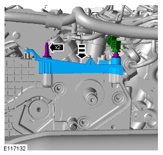
VACUUM CONTROL SOLENOIDS (WHERE FITTED)

| ITEM | DESCRIPTION |
|---|---|
| 1 | Vacuum reservoir |
| 2 | Vacuum connection to turbine intake shut-off valve (secondary turbocharger) |
| 3 | Turbine intake shut-off valve solenoid |
| 4 | Charge air shut-off valve solenoid |
| 5 | Pipe from left air cleaner |
| 6 | Pipe to cooling bypass solenoid of Exhaust Gas Recirculation (EGR) system |
| 7 | Pipe to vacuum actuator of charge air shut-off valve |
| 8 | Non return valve |
| 9 | Pipe from vacuum pump |
The turbine intake shut-off valve and charge air shut-off valve solenoids are installed on a bracket attached to the front of the Bank 2 cylinder head. The ECM operates the solenoids to apply and release the vacuum in the vacuum actuators of the turbine intake shut-off valve (located on the secondary turbocharger) and the charge air shut-off valve.
The vacuum for the actuators is produced by the vacuum pump on the rear of the Bank 1 cylinder head. For additional information, refer to:Engine (303-01A Engine - TDV6 3.0L Diesel /TDV6 3.0L Diesel - Gen 1.5/TDV6 3.0L Diesel - Gen 2, Description and Operation).
The solenoids are normally-closed valves installed in the vacuum line between the vacuum reservoir and their related vacuum actuator. Each solenoid is also connected to a line from the left air cleaner, which allows air into the vacuum lines to the actuators when the solenoids are de-energized.
PRINCIPLES OF VARIABLE VANE OPERATION
The turbine wheel of each turbocharger uses the engine exhaust gases to drive the compressor wheel. The compressor wheel draws in clean air, which is supplied to the engine cylinders in a compressed form.
The primary, VGT turbocharger allows the optimum inlet geometry (inlet area and flow angle) to be used over a wide range of engine operating conditions. This allows a rapid speed of response and higher charge air pressures at low engine speeds. The variable vane angle determines both the inlet area as well as the flow angle, as controlled by the ECM via the VGT actuator. The variable vanes allow efficient use of the exhaust gas energy which in turn improves turbocharger and engine efficiency.

A = LOW ENGINE SPEED; B = INTERMEDIATE ENGINE SPEED; C = MAXIMUM ENGINE SPEED.
| ITEM | DESCRIPTION |
|---|---|
| 1 | Engine Control Module (ECM) |
| 2 | Variable Geometry Turbine (VGT) vane actuator |
| 3 | Turbine housing |
| 4 | Variable vanes |
| 5 | Compressor wheel |
Low Engine Speed. At low engine speeds the volume of exhaust gas is low so the vanes are moved towards the closed position to reduce the turbine inlet area. This reduction causes an increase in the gas velocity into the turbine wheel thereby increasing wheel speed and charge air pressure.
Intermediate Engine Speed. As the engine speed increases and the volume of exhaust gas increases the vanes are moved towards the open position to increase the turbine inlet area and maintain the gas velocity.
Maximum Engine Speed. At maximum engine speed the vanes are almost fully open maintaining the gas velocity into the turbine wheel.
When the vehicle is driven at high altitudes the ambient pressure reduces causing the compressor wheel to rotate faster to achieve the same charge air pressure. To prevent the turbine wheel from over-speeding under these conditions, the ECM protects the turbocharger by opening the vanes further to reduce the turbine wheel speed. This is known as the altitude margin of the turbocharger, which occurs at altitudes above 2000 meters. Below 2000 meters altitude compensation is not necessary. The ECM uses an internal barometric pressure sensor to monitor altitude.
The maximum position of the turbocharger vanes (fully open) is also an emergency default position in the event of an electrical fault. This lowers the chance of engine damage due to excessive charge air pressure.
DUAL MODE BOOSTING (WHERE FITTED)
Ensure both ends of the pipe are securely connected to the secondary turbo and the air intake system to prevent damage to the turbo components.
The dual mode boosting system comprises two turbochargers and software within the ECM. The two turbochargers can operate in two modes; mono turbocharger operation or bi-turbocharger operation.
MONO TURBOCHARGER OPERATION

A = DIRTY AIR; B = CLEAN AIR; C = CHARGE AIR; D = EXHAUST GASES.
| ITEM | DESCRIPTION |
|---|---|
| 1 | Engine |
| 2 | Exhaust system left intake pipe |
| 3 | Primary turbocharger |
| 4 | Left intake grills |
| 5 | Left air cleaner |
| 6 | Left charge air cooler |
| 7 | Charge air shut-off valve |
| 8 | Charge air recirculation solenoid |
| 9 | Right charge air cooler |
| 10 | Right air cleaner |
| 11 | Right intake grills |
| 12 | Electric throttle |
| 13 | Secondary turbocharger |
| 14 | Exhaust system right intake pipe |
| 15 | Turbine shut-off valve |
Fresh air is drawn through the left air cleaner and the MAF (Mass Air Flow) sensor to the primary turbocharger compressor. The compressed air then passes through the charge air coolers and electric throttle to the intake manifolds.
The turbine shut-off valve on the secondary turbocharger is closed and therefore exhaust gases are unable to operate the secondary turbocharger turbine. In this condition all charge air pressure is produced by the primary turbocharger using the exhaust gases from all six cylinders.
If the engine idles for more than 3 minutes, the secondary turbocharger is actuated to keep the turbocharger shaft rotating, to prevent oil from leaking into the turbine housing. This is achieved by periodically opening the turbine intake shut-off valve to operate the turbocharger.
BI-TURBOCHARGER SWITCHING

A = DIRTY AIR; B = CLEAN AIR; C = CHARGE AIR; D = EXHAUST GASES.
| ITEM | DESCRIPTION |
|---|---|
| 1 | Engine |
| 2 | Exhaust system left intake pipe |
| 3 | Primary turbocharger |
| 4 | Left intake grills |
| 5 | Left air cleaner |
| 6 | Left charge air cooler |
| 7 | Charge air shut-off valve |
| 8 | Charge air recirculation solenoid |
| 9 | Right charge air cooler |
| 10 | Right air cleaner |
| 11 | Right intake grills |
| 12 | Electric throttle |
| 13 | Secondary turbocharger |
| 14 | Exhaust system right intake pipe |
| 15 | Turbine shut-off valve |
When the engine operating parameters approach the limits (approximately 2800 RPM under load) of the primary turbocharger, the ECM begins the switch to parallel bi-turbocharger operation. The secondary turbocharger is brought into operation by the opening of the turbine shut-off valve which allows exhaust gases to flow through the turbine. Fresh air is then drawn through the right air cleaner and the MAFT (Mass Air Flow and Temperature) sensor to the secondary turbocharger compressor.
Initially, the secondary turbocharger does not produce a charge air pressure to equal that of the primary turbocharger. Therefore, the charge air from the secondary turbocharger is fed via the recirculation solenoid into the clean air duct of the primary turbocharger.
BI-TURBOCHARGER OPERATION

A = DIRTY AIR; B = CLEAN AIR; C = CHARGE AIR; D = EXHAUST GASES.
| ITEM | DESCRIPTION |
|---|---|
| 1 | Engine |
| 2 | Exhaust system left intake pipe |
| 3 | Primary turbocharger |
| 4 | Left intake grills |
| 5 | Left air cleaner |
| 6 | Left charge air cooler |
| 7 | Charge air shut-off valve |
| 8 | Charge air recirculation solenoid |
| 9 | Right charge air cooler |
| 10 | Right air cleaner |
| 11 | Right intake grills |
| 12 | Electric throttle |
| 13 | Secondary turbocharger |
| 14 | Exhaust system right intake pipe |
| 15 | Turbine shut-off valve |
As the secondary turbocharger charge air pressure increases, the recirculation solenoid is closed and the charge air shut-off valve opened. This increases the charge air pressure from the secondary turbocharger and combines it with the charge air from the primary turbocharger.
The ECM maintains the turbochargers in bi-turbocharger mode until it determines that the engine operating parameters no longer require it. The ECM then switches the turbochargers back to mono turbocharger operation.
SHUT-OFF VALVE CONTROL
Turbine intake shut-off valve: If vacuum is released from the turbine intake shut-off valve it will default to the closed position. The turbine intake shut-off valve position sensor will inform the ECM, which will initiate mono-turbo mode, restrict engine performance and record a DTC.
Charge air shut-off valve: If vacuum is released from the charge air shut-off valve it will default to the closed position. In the default position, the ECM initiates mono-turbo operation and restricts engine torque. A DTC will also be recorded in the ECM.
CONTROL DIAGRAM - SHEET 1 OF 2 - VEHICLES WITH SINGLE TURBOCHARGER
A = Hardwired.

| ITEM | DESCRIPTION |
|---|---|
| 1 | Battery |
| 2 | Battery Junction Box 2 (BJB2) |
| 3 | Battery Junction Box (BJB) |
| 4 | Engine Junction Box (EJB) |
| 5 | Engine Control Module (ECM) |
| 6 | Variable Geometry Turbine (VGT) vane actuator |
| 7 | Charge air temperature sensor |
| 8 | Charge air pressure sensor |
CONTROL DIAGRAM - SHEET 2 OF 2 - TWIN TURBOCHARGER VARIANT VEHICLES

| ITEM | DESCRIPTION |
|---|---|
| 1 | Battery |
| 2 | Battery Junction Box 2 (BJB2) |
| 3 | Battery Junction Box (BJB) |
| 4 | Engine Junction Box (EJB) |
| 5 | Engine Control Module (ECM) |
| 6 | Variable Geometry Turbine (VGT) vane actuator |
| 7 | Charge air temperature sensor |
| 8 | Charge air pressure sensor |
| 9 | Turbine intake shut-off valve position sensor |
| 10 | Turbine intake shut-off valve solenoid |
| 11 | Charge air solenoid |
| 12 | Charge air recirculation solenoid |
FUEL CHARGING AND CONTROLS - TURBOCHARGER - TDV6 3.0L DIESEL
GEN 2 SINGLE TURBOCHARGER (G2055158)
TDV6 3.0L DIESEL - GEN 2 SINGLE TURBOCHARGER

| ITEM | DESCRIPTION |
|---|---|
| 1 | Vacuum reservoir |
| 2 | Variable Geometry Turbine (VGT)- Turbocharger |
| 3 | Vacuum pump (Brake servo assist and turbocharger oil supply pump) |
| 4 | Electronic Vacuum Regulating Valve (EVRV) - EGR control |
This variation of the TDV6 engine has a single Variable Geometry Turbine (VGT) turbocharger mounted on the left side of the engine. This turbocharger is slightly larger in size compared to the primary turbocharger fitted to the twin turbocharger variants of the TDV6 engine. The VGT makes it possible to vary the exhaust gas flow of the turbine, dependent on engine operation. This improves the power transfer to the turbine and compressor wheels, particularly at low engine speeds, thus increasing the boost pressure.
The VGT is connected by the charge air ducts of the intake air distribution and filtering system. For additional information, refer to:Intake Air Distribution and Filtering (303-12A Intake Air Distribution and Filtering - TDV6 3.0L Diesel /TDV6 3.0L Diesel - Gen 1.5/TDV6 3.0L Diesel - Gen 2, Description and Operation). The operation of the system is controlled by the Powertrain Control Module (PCM).
The turbocharger is also cooled with a feed from the main engine cooling system.
VARIABLE GEOMETRY TURBINE (VGT) - TURBOCHARGER

| ITEM | DESCRIPTION |
|---|---|
| 1 | Exhaust gas outlet to exhaust system |
| 2 | Exhaust gas inlet from exhaust manifold |
| 3 | Coolant outlet |
| 4 | Oil pressure supply from cylinder block |
| 5 | Vane actuator |
| 6 | Clean air inlet |
| 7 | Charge air outlet |
| 8 | Coolant feed from cylinder block |
| 9 | Oil feed connection |
| 10 | Oil return connection |
| 11 | Coolant connections |
| 12 | Vane actuator rod |
The Variable Geometry Turbine (VGT) - turbocharger is mounted to the left (bank 2) exhaust manifold.
On production vehicles, no gasket is used to seal the joint surface between the turbocharger and the exhaust manifold. In-service vehicles require a service gasket to be fitted if the joint is disturbed.
The turbocharger consists of two main elements, a turbine wheel and compressor wheel, enclosed separately in cast housings and mounted on a common shaft rotating on two ball bearing races. The ball bearings receive an engine oil feed for lubrication from an outlet at the rear of the engine block, oil then returns to the engine oil pan via an oil drain pipe. Gen 2 engines also have a coolant feed to the primary turbocharger housing from the engine cooling system.
An integral bracket on the compressor side of the turbocharger locates the VGT vane actuator. The VGT vane actuator is connected to an actuator rod which moves the turbine housing to adjust the position of the vanes. When the VGT vane actuator operates, a lever is rotated by a lever arm, which in turn moves the actuator rod and changes rotary motion into linear motion. The actuator rod is connected to a second lever arm attached to the outside of the turbine housing. The linear motion is converted back to rotary motion of the housing and adjusts the variable vanes within the VGT.
The VGT has a connection for the engine cooling circuit to provide the appropriate cooling efficiency of the ball bearing races.
The Powertrain Control Module (PCM) controls the output to the vane actuator motor using a Pulse Width Modulation (PWM) signal. The VGT vane actuator also provides the PCM with a positional feedback signal to determine the pitch angle of the vanes. An angular position sensor in the motor is provided with a 5V reference voltage from the PCM. The position sensor returns a ground and a signal voltage proportional to the actuator position.
The variable vanes in the turbocharger improve the exhaust gas power transfer to the turbine wheel which in turn drives the compressor wheel. This greatly assists the increase in charge air pressure at low engine speeds.
TURBOCHARGER OIL LUBRICATION SYSTEM

| ITEM | DESCRIPTION |
|---|---|
| 1 | Oil feed to turbocharger |
| 2 | Oil feed from cylinder block (T piece) |
| 3 | Vacuum pump (Brake servo assist and turbocharger oil supply pump) |
| 4 | Oil feed from turbocharger oil reservoir |
| 5 | Turbocharger oil reservoir oil filter |
| 6 | Vent pipe |
| 7 | Connection to oil pan oil return pipe |
| 8 | Turbocharger oil return pipe |
| 9 | Variable Geometry Turbine (VGT)- turbocharger |
| 10 | Turbocharger oil reservoir |
| 11 | Oil pan |
| 12 | Vent pipe |
The TDV6 turbocharger system has an oil circuit which is primarily supplied by the engine oil pump and fed to the housing of the turbocharger via an outlet at the back of the cylinder block. Land Rover variants of the TDV6 engine have a vacuum pump driven off the the exhaust camshaft on bank 1, this provides brake booster vacuum and also turbocharger oil supply in certain conditions. The vacuum pump draws oil from a dedicated reservoir within the oil pan via a filter, this oil is then fed to the turbocharger via a port in the cylinder head. The secondary oil feed supplied by the vacuum pump is to make sure that there is adequate lubrication of the bearing races and housing when the vehicle is manoeuvring at extreme angles. The reservoir is replenished with oil from the drain tube below the turbocharger, it also has a breather tube into the cylinder block.
See oil flow diagram at the end of this document.
PRINCIPLES OF VARIABLE VANE OPERATION
Exhaust gases are used to drive the compressor wheel. The compressor wheel draws in clean air, which is supplied to the charge air coolers in a compressed form.
The VGT turbocharger allows the optimum inlet geometry (inlet area and flow angle) to be used over a wide range of engine operating conditions. This allows a rapid response speed and higher charge air pressures at low engine speeds. The variable vane angle determines both the inlet area as well as the flow angle, as controlled by the Powertrain Control Module (PCM) via the VGT vane actuator. The variable vanes allow efficient use of the exhaust gas energy which improves turbocharger and engine efficiency.

A = LOW ENGINE SPEED; B = INTERMEDIATE ENGINE SPEED; C = MAXIMUM ENGINE SPEED.
| ITEM | DESCRIPTION |
|---|---|
| 1 | Powertrain Control Module (PCM) |
| 2 | Primary vane actuator |
| 3 | Turbine housing |
| 4 | Variable vanes |
| 5 | Compressor wheel |
Low Engine Speed: At low engine speeds the volume of exhaust gas is low, so the vanes are moved towards the closed position to reduce the turbine inlet area. This reduction causes an increase in the gas velocity into the turbine wheel, thereby increasing turbine speed and charge air pressure.
Intermediate Engine Speed: As the engine speed increases and the volume of exhaust gas increases the vanes are moved towards the open position to increase the turbine inlet area and maintain the gas velocity.
Maximum Engine Speed: At maximum engine speed the vanes are almost fully open maintaining the gas velocity into the turbine wheel.
When the vehicle is driven at high altitudes the ambient pressure reduces, causing the compressor wheel to rotate faster to achieve the same charge air pressure. To prevent the turbine wheel from over-speeding under these conditions, the Powertrain Control Module (PCM) protects the turbocharger by opening the vanes further to reduce the turbine wheel speed. This is known as the altitude margin of the turbocharger, which occurs at altitudes above 2000 meters. Below 2000 meters altitude compensation is not necessary. The PCM uses an internal barometric pressure sensor to monitor altitude.
The maximum position of the turbocharger vanes (fully open) is also an emergency default position in the event of an electrical fault. This lowers the chance of engine damage due to excessive charge air pressure.
TDV6 3.0L DIESEL - GEN 2 SINGLE TURBOCHARGER OPERATION

A = DIRTY AIR: B = CLEAN AIR: C = COMPRESSED AIR: D = EXHAUST GAS.
| ITEM | DESCRIPTION |
|---|---|
| 1 | Engine |
| 2 | Variable Geometry Turbine (VGT)- Turbocharger |
| 3 | Intake air filter |
| 4 | Charge air cooler |
| 5 | Electric throttle |
Fresh air is drawn through the left intake air filter to the turbocharger compressor. The compressed air then passes through the charge air cooler and electric throttle to the intake manifolds.

A = COOL OIL: B = HOT OIL.
| ITEM | DESCRIPTION |
|---|---|
| 1 | Cylinder head |
| 2 | Cylinder block |
| 3 | Vacuum pump (Vacuum and turbocharger scavenge oil pump) |
| 4 | Turbocharger Oil Supply Filter |
| 5 | Turbocharger Oil Reservoir |
| 6 | Oil Pan |
| 7 | Turbocharger |
TDV6 3.0L DIESEL - GEN 2 SINGLE TURBOCHARGER

A = HARDWIRED: AL = PULSE WIDTH MODULATION (PWM).
| ITEM | DESCRIPTION |
|---|---|
| 1 | Powertrain Control Module (PCM) |
| 2 | Vane actuator |
| 3 | Ground |
| 4 | Supply |
| 5 | Charge air pressure sensor |
| 6 | Charge air temperature sensor |
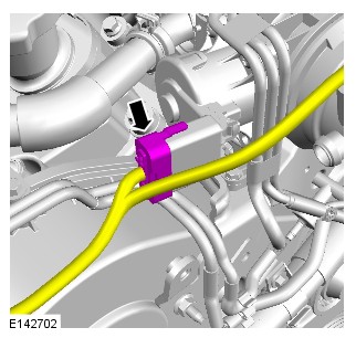
VACUUM SYSTEM

A = VACUUM SUPPLY: B = VACUUM VENT: C = VACUUM SUPPLY AND VENT: D = FLOW
| ITEM | DESCRIPTION |
|---|---|
| 1 | Exhaust Gas Recirculation (EGR) valves |
| 2 | Electronic Vacuum Regulating Valve (EVRV) - (EGR) valve bypass valve |
| 3 | Active engine mounts |
| 4 | Clean air filter housing |
| 5 | Electronic Vacuum Regulating Valve (EVRV) - Active engine mount solenoid |
| 6 | Brake vacuum reservoir |
| 7 | Brake vacuum non return valve |
| 8 | Vacuum Pump (Vacuum and turbocharger scavenge oil pump) |
| 9 | Vacuum reservoir |
FUEL CHARGING AND CONTROLS - TURBOCHARGER - TDV6 3.0L DIESEL
TURBOCHARGER (G1882792)
For a detailed description of the fuel charging and controls system and operation, refer to the relevant Description and Operation section of the workshop manual. REFER to:Turbocharger (303-04B Fuel Charging and Controls - Turbocharger - TDV6 3.0L Diesel, Description and Operation).
The following tests may involve working in close proximity to hot components. Make sure adequate protection is used. Failure to follow this instruction may result in personal injury.
Diagnosis by substitution from a donor vehicle is NOT acceptable. Substitution of control modules does not guarantee confirmation of a fault and may also cause additional faults in the vehicle being checked and/or the donor vehicle.
Check and rectify basic faults before beginning diagnostic routines involving pinpoint tests.
- Verify the customer concern.
- Visually inspect for obvious signs of mechanical or electrical damage.
Visual Inspection
| MECHANICAL | ELECTRICAL |
|---|---|
|
|
- If an obvious cause for an observed or reported concern is found, correct the cause (if possible) before proceeding to the next step.
- If the cause is not visually evident, verify the symptom and refer to the Symptom Chart, alternatively check for Diagnostic Trouble Code(s) (DTC)s and refer to the DTC Index.
- Check JLR claims submission system for open campaigns. Refer to the corresponding bulletins and SSMs which may be valid for the specific customer complaint and complete the recommendations as required.
| SYMPTOM | POSSIBLE CAUSES | ACTION |
|---|---|---|
| Poor performance |
|
Check the fuel level and condition. Draw off approximately 1 ltr (2.11 pints) of fuel and allow to stand for 1 minute. Check to make sure there is no separation of the fuel indicating water or other liquid in the fuel. Check the intake air system for restriction. Check the engine condition, compressions, etc if there are indications of a mechanical fault. Check for DTCs indicating a module fault. Refer to the warranty policy and procedures manual if a powertrain control module is at fault |
| No boost |
|
Check the electrical connections and harnesses. Check the intake air system for restriction/leakage. Check the turbocharger actuators and circuits. Refer to the electrical guides. Check the turbochargers for wear. Disconnect the turbocharger intake and outlet pipework and turn the turbochargers by hand. Any roughness indicates a fault. Check any up and down movement in the turbocharger shafts. Excessive movement indicates a fault. If in doubt, compare the unit with a new turbocharger. Check for DTCs indicating an actuator or module fault. Refer to the warranty policy and procedures manual if a powertrain control module is at fault |
| No boost/excessive noise |
|
Disconnect the turbocharger intake and outlet pipework and turn the turbochargers by hand. Any roughness indicates a fault. Check any up and down movement in the turbocharger shafts. Excessive movement indicates a fault. If in doubt, compare the unit with a new turbocharger. |
| Oil on the turbocharger assembly |
|
NOTE:
DO NOT replace the turbocharger for an oil leak issue until investigations have been made to establish the source of the oil leak. In most cases it is NOT the turbocharger that is at fault.
|
| PID | DESCRIPTION | ACTION |
|---|---|---|
| 0X0347 | Boost Pressure Actuator Bank 2 − Measured Position |
NOTE:
The datalogger signals are applicable only for TDV6
|
| 0X03E0 | Boost Pressure Actuator Bank 2 − Desired position |
NOTE:
The datalogger signals are applicable only for TDV6
|

| ITEM | DESCRIPTION |
|---|---|
| 1 | High pressure Exhaust Gas Recirculation (EGR)(s) (1 or 2 may be fitted) |
| 2 | EGR Cooler bypass valve solenoid |
| 3 | Active engine mounts (x2) (where fitted) |
| 4 | Active engine mount solenoid (where fitted) |
| 5 | Turbine intake shut-off valve |
| 6 | Turbine intake shut-off valve solenoid |
| 7 | Charge air shut-off valve |
| 8 | Charge air shut-off valve solenoid |
| 9 | Air filter housing |
| 10 | Vacuum reservoir |
| 11 | Non return valve |
| 12 | Vacuum pump |
| 13 | Non return valve |
| 14 | Brake servo |
| A | Vacuum supply hose |
| B | Vacuum vent hose |
| C | Actuator vacuum supply and vent hose |
| D | Direction of flow |
| TP | Pin point test reference - Test Point |
Refit any hoses that have been disconnected before moving on to the next step
| A2: VACUUM VENT HOSE TEST 2 | |
|---|---|
| TEST CONDITIONS | DETAILS/RESULTS/ACTIONS |
|
1
Disconnect the vacuum vent hose from the turbine intake shut-off valve solenoid at point TP2
|
|
|
2
Connect the vacuum pump to the vent hose at point TP2 and apply a vacuum
|
|
|
|
Can a vacuum be achieved?
Yes
Check the vacuum vent hose for a blockage between the turbine intake shut-off valve solenoid and the air filter housing
No
If a vacuum cannot be achieved the vent hose is functioning correctly
Repeat the test for the charge air shut-off valve vent hose connecting the gauge at point TP3
If the turbine intake shut-off valve and the charge air shut-off valve vent hoses are functioning correctly GO toA3.
|


For a list of Diagnostic Trouble Codes that could be set on this vehicle, please refer to Section 100-00. REFER to: Diagnostic Trouble Code Index - TDV6 3.0L Diesel , DTC: Powertrain Control Module (PCM) (100-00 General Information, Description and Operation).
Repairs
FUEL CHARGING AND CONTROLS - TURBOCHARGER - TDV6 3.0L DIESEL
LEFT TURBOCHARGER (G2354514)
| Name | Quantity | Part Number |
|---|---|---|
| EGR inlet pipe to exhaust gasket | 1 | LR078958 |
| Engine compartment brace bolts | 8 | LR037935 |
| Exhaust gas recirculation gasket | 1 | LR075627 |
| Exhaust manifold to turbocharger nuts | 3 | LR106277 |
| Left exhaust downpipe gasket | 1 | LR016619 |
| Lower oil return pipe gasket | 1 | LR013234 |
| Oil pan drain plug | 1 | 1013938 |
| Retaining clip | 1 | LR063121 |
| Right exhaust downpipe gasket | 1 | LR016621 |
| Turbocharger coolant pipes to turbocharger gasket | 1 | LR062102 |
| Turbocharger oil feed pipe banjo bolt washers | 2 | 1372726 |
| Turbocharger oil supply pipe banjo bolt | 1 | LR023967 |
| Turbocharger to exhaust manifold gasket | 1 | LR084664 |
| Upper oil return pipe gasket | 1 | LR013235 |
| Name | Quantity | Part Number | VIN range from | VIN range to |
|---|---|---|---|---|
| Turbocharger | 1 | LR061996 | FA000001 | GA568271 |
| Turbocharger | 1 | LR084606 | GA568272 |
| Name | Quantity | Part Number | VIN range from | VIN range to |
|---|---|---|---|---|
| Primary turbocharger | 1 | LR029915 | EA326005 | |
| Primary turbocharger | 1 | LR056369 | EA326006 | |
| Primary turbocharger | 1 | LR061998 | FA000001 | GA554433 |
| Primary turbocharger | 1 | LR084605 | GA554434 |
| Adaptor, Cooling System Vacuum Refill Kit
JLR-303-1634
|
 |
| Coolant System Vacuum Refill Kit
HU-919
|
 |
| Oil Extraction Kit
JLR-303-1644
|
 |
| Remover/Installer, Driveshaft Nut
JLR-205-993
|
 |
| Viscous Coupling Wrench
303-1142
|
 |
| Wrench, H02S
310-121
|
 |
PUBLISHED: 03-SEP-2019
2017.0 RANGE ROVER SPORT (LW), 303-04B
FUEL CHARGING AND CONTROLS - TURBOCHARGER - TDV6 3.0L DIESEL
LEFT TURBOCHARGER - TDV6 3.0L DIESEL /TDV6 3.0L DIESEL - GEN 1.5 (G1509438)
- 19.42.56
- TURBOCHARGER - LH - RENEW
- 3000 CC, TDV6, DIESEL, WITH PARTICULATE FILTER, WITH DIESEL EXHAUST FLUID, IC
- 4.80
- USED WITHINS
GENERAL EQUIPMENT
| EQUIPMENT NAME |
|---|
| Jaguar Land Rover approved diagnostic equipment |
PART(S)
| STEP | PART NAME | QUANTITY |
|---|---|---|
| Installation Step 1 | Turbocharger coolant pipes to turbocharger gasket | 1 |
| Installation Step 2 | Exhaust manifold to turbocharger nuts | 3 |
| Installation Step 2 | Turbocharger to exhaust manifold gasket | 1 |
| Installation Step 7 | Turbocharger oil supply pipe banjo bolt | 1 |
| Installation Step 7 | Turbocharger oil feed pipe banjo bolt washers | 2 |
| Installation Step 9 | Lower oil return pipe gasket | 1 |
| Installation Step 9 | Upper oil return pipe gasket | 1 |
Before disconnecting any components, make sure the area is clean and free from foreign material. When disconnected all openings must be sealed.
-
This procedure contains some variation in the illustrations depending on the vehicle specification, but the essential information is always correct.
-
This procedure contains illustrations showing certain components removed to provide extra clarity.
- Remove the engine undershield.
Refer to:Engine Undershield (501-02 Front End Body Panels, Removal and Installation).
- Drain the engine oil.
Refer to:Engine Oil Vacuum Draining and Filling (303-01A Engine - TDV6 3.0L Diesel /TDV6 3.0L Diesel - Gen 1.5/TDV6 3.0L Diesel - Gen 2, General Procedures).
- Remove the exhaust.
Refer to:Exhaust System - Vehicles With: Diesel Particulate Filter (DPF) (309-00A Exhaust System - TDV6 3.0L Diesel - Gen 2, Removal and Installation).Refer to:Exhaust System - Vehicles With: Diesel Particulate Filter (DPF) (309-00A Exhaust System - TDV6 3.0L Diesel - Gen 2, Removal and Installation).
- Remove the left Exhaust Gas Recirculation (EGR) valve.
Refer to:Left Exhaust Gas Recirculation Valve - TDV6 3.0L Diesel - Gen 2 (303-08A Engine Emission Control - TDV6 3.0L Diesel /TDV6 3.0L Diesel - Gen 1.5/TDV6 3.0L Diesel - Gen 2, Removal and Installation).


-
- Install the turbocharger coolant pipe.
Torque: 9Nm
- Install a new gasket.
- Install the turbocharger coolant pipe.
-
- Install the turbocharger.
Torque: 26Nm
- Install new nuts.
- Install a new gasket.
- Install the turbocharger.
- Install the exhaust manifold heatshield.
-
- Connect the turbocharger coolant pipes.
Torque: 10Nm
- Connect the turbocharger coolant pipes.
-
CAUTION:
Apply Loctite 243 to the bolts.
NOTE:Make sure to clean the threads prior to installation.
- Install the turbocharger retaining bracket.
- Install the 4 bolts.
Torque: 32Nm
-
- Connect the electrical connector to the turbocharger.
- Connect the Crankshaft Position Sensor (CKP) electrical connector.
-
- Install a new turbocharger oil feed pipe bolt.
Torque: 30Nm
- Install new washers.
- Install a new turbocharger oil feed pipe bolt.
- Install the turbocharger heatshield.
Torque: 9Nm
-
CAUTION:
Make sure that the area around the component is clean and free of foreign material.
- Install the turbocharger oil return pipe.
Torque: 9Nm
- Install new gaskets.
- Install the turbocharger oil return pipe.
- Install the air intake pipe.
Torque: 10Nm
- Install the left Exhaust Gas Recirculation (EGR) valve.
Refer to:Left Exhaust Gas Recirculation Valve - TDV6 3.0L Diesel - Gen 2 (303-08A Engine Emission Control - TDV6 3.0L Diesel /TDV6 3.0L Diesel - Gen 1.5/TDV6 3.0L Diesel - Gen 2, Removal and Installation).
- Install the exhaust.
Refer to:Exhaust System - Vehicles With: Diesel Particulate Filter (DPF) (309-00A Exhaust System - TDV6 3.0L Diesel - Gen 2, Removal and Installation).Refer to:Exhaust System - Vehicles With: Diesel Particulate Filter (DPF) (309-00A Exhaust System - TDV6 3.0L Diesel - Gen 2, Removal and Installation).
- Install the engine undershield.
Refer to:Engine Undershield (501-02 Front End Body Panels, Removal and Installation).
- Fill the engine with oil.
Refer to:Engine Oil Vacuum Draining and Filling (303-01A Engine - TDV6 3.0L Diesel /TDV6 3.0L Diesel - Gen 1.5/TDV6 3.0L Diesel - Gen 2, General Procedures).
- If a new component has been installed, configure using the Jaguar Land Rover approved diagnostic equipment.
General Equipment: Jaguar Land Rover approved diagnostic equipment
Removal and Installation
UEL CHARGING AND CONTROLS - TURBOCHARGER - TDV6 3.0L DIESEL
LEFT TURBOCHARGER - TDV6 3.0L DIESEL - GEN 2, VEHICLES WITHOUT: HYBRID SYSTEM (G1875337)
- 19.42.56
- TURBOCHARGER - LH - RENEW
- 3000 CC, TDV6, DIESEL, WITH PARTICULATE FILTER, WITH DIESEL EXHAUST FLUID, IC
- 4.80
- USED WITHINS
SPECIAL TOOL(S)

303-1069
Adapter, Wrench
GENERAL EQUIPMENT
| EQUIPMENT NAME |
|---|
| Jaguar Land Rover approved diagnostic equipment |
PART(S)
| STEP | PART NAME | QUANTITY |
|---|---|---|
| Installation Step 1 | Turbocharger coolant pipes to turbocharger gasket | 1 |
| Installation Step 2 | Turbocharger to exhaust manifold gasket | 1 |
| Installation Step 2 | Exhaust manifold to turbocharger nuts | 3 |
| Installation Step 7 | Turbocharger oil feed pipe banjo bolt washers | 2 |
| Installation Step 7 | Turbocharger oil supply pipe banjo bolt | 1 |
| Installation Step 9 | Lower oil return pipe gasket | 1 |
| Installation Step 9 | Upper oil return pipe gasket | 1 |
Before disconnecting any components, make sure the area is clean and free from foreign material. When disconnected all openings must be sealed.
-
This procedure contains some variation in the illustrations depending on the vehicle specification, but the essential information is always correct.
-
This procedure contains illustrations showing certain components removed to provide extra clarity.
- Raise and support the vehicle on a suitable 2 post lift.
Refer to:Lifting (100-02 Jacking and Lifting, Description and Operation).
- Drain the engine oil.
Refer to:Engine Oil Draining and Filling (303-01A Engine - TDV6 3.0L Diesel /TDV6 3.0L Diesel - Gen 1.5/TDV6 3.0L Diesel - Gen 2, General Procedures).
- Remove the exhaust system.
Refer to:Exhaust System - Vehicles With: Diesel Particulate Filter (DPF) (309-00A Exhaust System - TDV6 3.0L Diesel - Gen 2, Removal and Installation).Refer to:Exhaust System - Vehicles Without: Diesel Particulate Filter (DPF) (309-00A Exhaust System - TDV6 3.0L Diesel - Gen 2, Removal and Installation).
- Remove the transmission fluid cooler pipes.
Refer to:Transmission Fluid Cooler Pipes - TDV6 3.0L Diesel /TDV6 3.0L Diesel - Gen 1.5/TDV6 3.0L Diesel - Gen 2 (307-02A Transmission/Transaxle Cooling - Vehicles With: 8HP70 8-Speed Automatic Transmission AWD, Removal and Installation).
- Remove the left exhaust gas recirculation valve.
Refer to:Left Exhaust Gas Recirculation Valve - TDV6 3.0L Diesel - Gen 2 (303-08A Engine Emission Control - TDV6 3.0L Diesel /TDV6 3.0L Diesel - Gen 1.5/TDV6 3.0L Diesel - Gen 2, Removal and Installation).
-
Use the special tool to remove and discard the turbocharger nut.Special Tool(s): 303-1069

-
- Install a new gasket.
- Install the coolant pipe to turbocharger assembly.
- Install and tighten the 2 bolts.
Torque: 9Nm
-
- Install a new turbocharger to manifold gasket.
- Install the turbocharger.
- Install and tighten 2 new nuts.
Torque: 26Nm
- Use the special tool to install and tighten the new nut.
Special Tool(s): 303-1069Torque: 26Nm
-
- Install the exhaust manifold heatshield.
- Install and tighten the 3 bolts.
Torque: 9Nm
-
- Reposition the turbocharger coolant pipes.
- Install and tighten the 2 bolts.
Torque: 10Nm
-
CAUTION:
Apply Loctite 243 to the bolts.
NOTE:Make sure to clean the threads prior to installation.
- Install the turbocharger bracket.
- Install and tighten the 4 bolts.
Torque: 32Nm
-
- Connect the electrical connector to the turbocharger.
- Connect the electrical connector to the Crankshaft Position Sensor (CKP).
-
- Install new washers.
- Install and tighten a new turbocharger oil feed pipe bolt.
Torque: 30Nm
-
- Install the turbocharger heatshield.
- Install and tighten the 2 bolts.
Torque: 9Nm
-
CAUTION:
Make sure that the area around the component is clean and free of foreign material.
- Install new upper and lower turbocharger oil return pipe gaskets.
- Install the turbocharger oil return pipe.
- Install and tighten the 4 bolts.
Torque: 9Nm
-
- Install the air intake pipe.
- Install and tighten the nut.
Torque: 10Nm
- Install the left exhaust gas recirculation valve.
Refer to:Left Exhaust Gas Recirculation Valve - TDV6 3.0L Diesel - Gen 2 (303-08A Engine Emission Control - TDV6 3.0L Diesel /TDV6 3.0L Diesel - Gen 1.5/TDV6 3.0L Diesel - Gen 2, Removal and Installation).
- Install the transmission fluid cooler pipes.
Refer to:Transmission Fluid Cooler Pipes - TDV6 3.0L Diesel /TDV6 3.0L Diesel - Gen 1.5/TDV6 3.0L Diesel - Gen 2 (307-02A Transmission/Transaxle Cooling - Vehicles With: 8HP70 8-Speed Automatic Transmission AWD, Removal and Installation).
- Install the exhaust system.
Refer to:Exhaust System - Vehicles Without: Diesel Particulate Filter (DPF) (309-00A Exhaust System - TDV6 3.0L Diesel - Gen 2, Removal and Installation).Refer to:Exhaust System - Vehicles With: Diesel Particulate Filter (DPF) (309-00A Exhaust System - TDV6 3.0L Diesel - Gen 2, Removal and Installation).
- Refill the engine oil.
Refer to:Engine Oil Draining and Filling (303-01A Engine - TDV6 3.0L Diesel /TDV6 3.0L Diesel - Gen 1.5/TDV6 3.0L Diesel - Gen 2, General Procedures).
- If a new component has been installed, configure using the Jaguar Land Rover approved diagnostic equipment.
General Equipment: Jaguar Land Rover approved diagnostic equipment
FUEL CHARGING AND CONTROLS - TURBOCHARGER - TDV6 3.0L DIESEL
TURBOCHARGER BYPASS VALVE (G1509440)
- 19.42.63
- TURBOCHARGER BYPASS VALVE - RENEW
- 3000 CC, TDV6
- 0.40
- USED WITHINS
PART(S)
| STEP | PART NAME | QUANTITY |
|---|---|---|
| Removal Step 4 | Intake air shutoff throttle seals | 1 |
Removal steps in this procedure may contain installation details.


- To install, reverse the removal procedure.
FUEL CHARGING AND CONTROLS - TURBOCHARGER - TDV6 3.0L DIESEL
FIXED VANE TURBOCHARGER ACTUATOR (G1509441)
- 19.42.64
- FIXED VANE TURBOCHARGER ACTUATOR - RENEW
- 3000 CC, TDV6, WITH PARTICULATE FILTER, WITH DIESEL EXHAUST FLUID
- 2.40
- USED WITHINS
PART(S)
| STEP | PART NAME | QUANTITY |
|---|---|---|
| Installation Step 1 | Fixed vane turbocharger actuator gasket kit | 1 |
Some variation in the illustrations may occur, but the essential information is always correct.
-
Raise and support the vehicle.WARNING:
Make sure to support the vehicle with axle stands.
-
Refer to:Exhaust System - Vehicles With: Diesel Particulate Filter (DPF) (309-00A Exhaust System - TDV6 3.0L Diesel - Gen 2, Removal and Installation).Refer to:Exhaust System - Vehicles Without: Diesel Particulate Filter (DPF) (309-00A Exhaust System - TDV6 3.0L Diesel - Gen 2, Removal and Installation).
-
Refer to:Engine Undershield (501-02 Front End Body Panels, Removal and Installation).


-
Refer to:Engine Undershield (501-02 Front End Body Panels, Removal and Installation).
-
Refer to:Exhaust System - Vehicles With: Diesel Particulate Filter (DPF) (309-00A Exhaust System - TDV6 3.0L Diesel - Gen 2, Removal and Installation).Refer to:Exhaust System - Vehicles Without: Diesel Particulate Filter (DPF) (309-00A Exhaust System - TDV6 3.0L Diesel - Gen 2, Removal and Installation).
- If a new fixed vane turbocharger actuator is installed, carry out the reset procedure for the fixed vane turbocharger actuator using approved diagnostic tool.
FUEL CHARGING AND CONTROLS - TURBOCHARGER - TDV6 3.0L DIESEL
LEFT TURBOCHARGER - TDV6 3.0L DIESEL /TDV6 3.0L DIESEL - GEN 1.5 (G1509438)
- 19.42.56
- TURBOCHARGER - LH - RENEW
- 3000 CC, TDV6, DIESEL, WITH PARTICULATE FILTER, WITH DIESEL EXHAUST FLUID, IC
- 4.80
- USED WITHINS
GENERAL EQUIPMENT
| EQUIPMENT NAME |
|---|
| Jaguar Land Rover approved diagnostic equipment |
PART(S)
| STEP | PART NAME | QUANTITY |
|---|---|---|
| Installation Step 1 | Turbocharger coolant pipes to turbocharger gasket | 1 |
| Installation Step 2 | Exhaust manifold to turbocharger nuts | 3 |
| Installation Step 2 | Turbocharger to exhaust manifold gasket | 1 |
| Installation Step 7 | Turbocharger oil supply pipe banjo bolt | 1 |
| Installation Step 7 | Turbocharger oil feed pipe banjo bolt washers | 2 |
| Installation Step 9 | Lower oil return pipe gasket | 1 |
| Installation Step 9 | Upper oil return pipe gasket | 1 |
Before disconnecting any components, make sure the area is clean and free from foreign material. When disconnected all openings must be sealed.
-
This procedure contains some variation in the illustrations depending on the vehicle specification, but the essential information is always correct.
-
This procedure contains illustrations showing certain components removed to provide extra clarity.
- Remove the engine undershield.
Refer to:Engine Undershield (501-02 Front End Body Panels, Removal and Installation).
- Drain the engine oil.
Refer to:Engine Oil Vacuum Draining and Filling (303-01A Engine - TDV6 3.0L Diesel /TDV6 3.0L Diesel - Gen 1.5/TDV6 3.0L Diesel - Gen 2, General Procedures).
- Remove the exhaust.
Refer to:Exhaust System - Vehicles With: Diesel Particulate Filter (DPF) (309-00A Exhaust System - TDV6 3.0L Diesel - Gen 2, Removal and Installation).Refer to:Exhaust System - Vehicles With: Diesel Particulate Filter (DPF) (309-00A Exhaust System - TDV6 3.0L Diesel - Gen 2, Removal and Installation).
- Remove the left Exhaust Gas Recirculation (EGR) valve.
Refer to:Left Exhaust Gas Recirculation Valve - TDV6 3.0L Diesel - Gen 2 (303-08A Engine Emission Control - TDV6 3.0L Diesel /TDV6 3.0L Diesel - Gen 1.5/TDV6 3.0L Diesel - Gen 2, Removal and Installation).
-
- Install the turbocharger coolant pipe.
Torque: 9Nm
- Install a new gasket.
- Install the turbocharger coolant pipe.
-
- Install the turbocharger.
Torque: 26Nm
- Install new nuts.
- Install a new gasket.
- Install the turbocharger.
- Install the exhaust manifold heatshield.
-
- Connect the turbocharger coolant pipes.
Torque: 10Nm
- Connect the turbocharger coolant pipes.
-
CAUTION:
Apply Loctite 243 to the bolts.
NOTE:Make sure to clean the threads prior to installation.
- Install the turbocharger retaining bracket.
- Install the 4 bolts.
Torque: 32Nm
-
- Connect the electrical connector to the turbocharger.
- Connect the Crankshaft Position Sensor (CKP) electrical connector.
-
- Install a new turbocharger oil feed pipe bolt.
Torque: 30Nm
- Install new washers.
- Install a new turbocharger oil feed pipe bolt.
- Install the turbocharger heatshield.
Torque: 9Nm
-
CAUTION:
Make sure that the area around the component is clean and free of foreign material.
- Install the turbocharger oil return pipe.
Torque: 9Nm
- Install new gaskets.
- Install the turbocharger oil return pipe.
- Install the air intake pipe.
Torque: 10Nm
- Install the left Exhaust Gas Recirculation (EGR) valve.
Refer to:Left Exhaust Gas Recirculation Valve - TDV6 3.0L Diesel - Gen 2 (303-08A Engine Emission Control - TDV6 3.0L Diesel /TDV6 3.0L Diesel - Gen 1.5/TDV6 3.0L Diesel - Gen 2, Removal and Installation).
- Install the exhaust.
Refer to:Exhaust System - Vehicles With: Diesel Particulate Filter (DPF) (309-00A Exhaust System - TDV6 3.0L Diesel - Gen 2, Removal and Installation).Refer to:Exhaust System - Vehicles With: Diesel Particulate Filter (DPF) (309-00A Exhaust System - TDV6 3.0L Diesel - Gen 2, Removal and Installation).
- Install the engine undershield.
Refer to:Engine Undershield (501-02 Front End Body Panels, Removal and Installation).
- Fill the engine with oil.
Refer to:Engine Oil Vacuum Draining and Filling (303-01A Engine - TDV6 3.0L Diesel /TDV6 3.0L Diesel - Gen 1.5/TDV6 3.0L Diesel - Gen 2, General Procedures).
- If a new component has been installed, configure using the Jaguar Land Rover approved diagnostic equipment.
FUEL CHARGING AND CONTROLS - TURBOCHARGER - TDV6 3.0L DIESEL
LEFT TURBOCHARGER - TDV6 3.0L DIESEL - GEN 2, VEHICLES WITH: HYBRID SYSTEM (G1883049)
- 19.42.56
- TURBOCHARGER - LH - RENEW
- 3000 CC, TDV6, DIESEL, WITH PARTICULATE FILTER, WITH DIESEL EXHAUST FLUID, IC
- 4.80
- USED WITHINS
GENERAL EQUIPMENT
| EQUIPMENT NAME |
|---|
| Jaguar Land Rover approved diagnostic equipment |
PART(S)
| STEP | PART NAME | QUANTITY |
|---|---|---|
| Removal Step 8 | Turbocharger oil return pipe gasket(s) | 1 |
| Removal Step 9 | Turbocharger oil return pipe gasket(s) | 1 |
| Removal Step 11 | Turbocharger oil feed pipe banjo bolt washers | 1 |
| Removal Step 11 | Turbocharger oil supply pipe banjo bolt | 1 |
| Removal Step 14 | EGR inlet pipe to EGR valve gasket | 1 |
| Removal Step 18 | Turbocharger coolant pipe | 1 |
| Removal Step 20 | Exhaust manifold to turbocharger nuts | 1 |
| Removal Step 21 | Exhaust manifold to turbocharger nuts | 2 |
| Removal Step 21 | Turbocharger to exhaust manifold gasket | 1 |
| Removal Step 22 | Turbocharger coolant pipes to turbocharger gasket | 1 |
Before disconnecting any components, make sure the area is clean and free from foreign material. When disconnected all openings must be sealed.
-
Some variation in the illustrations may occur, but the essential information is always correct.
-
Removal steps in this procedure may contain installation details.
-
Refer to:Hybrid Electric Vehicle Power Down/Up (414-01 Battery, Mounting and Cables, General Procedures).
-
Refer to:Engine Oil Draining and Filling (303-01A Engine - TDV6 3.0L Diesel /TDV6 3.0L Diesel - Gen 1.5/TDV6 3.0L Diesel - Gen 2, General Procedures).
-
Refer to:Exhaust System - Vehicles With: Diesel Exhaust Fluid (309-00A Exhaust System - TDV6 3.0L Diesel - Gen 2, Removal and Installation).
-
Refer to:Transmission Fluid Cooler Pipes - TDV6 3.0L Diesel /TDV6 3.0L Diesel - Gen 1.5/TDV6 3.0L Diesel - Gen 2 (307-02B Transmission/Transaxle Cooling - Vehicles With: 8HP70 8-Speed - Hybrid Electric Vehicle - Automatic Transmission – AWD, Removal and Installation).
-
Refer to:Left Exhaust Gas Recirculation Valve - TDV6 3.0L Diesel - Gen 2 (303-08A Engine Emission Control - TDV6 3.0L Diesel /TDV6 3.0L Diesel - Gen 1.5/TDV6 3.0L Diesel - Gen 2, Removal and Installation).


- e.
- Install the exhaust manifold heatshield.
Torque: 11Nm
- Install the exhaust heatshield.
Torque: 9Nm


- Install the starter motor.
Refer to:Starter Motor (303-06A Starting System - TDV6 3.0L Diesel /TDV6 3.0L Diesel - Gen 1.5/TDV6 3.0L Diesel - Gen 2, Removal and Installation).
- Install the EGR valve.
Refer to:Right Exhaust Gas Recirculation Valve (303-08A Engine Emission Control - TDV6 3.0L Diesel /TDV6 3.0L Diesel - Gen 1.5/TDV6 3.0L Diesel - Gen 2, Removal and Installation).
- Refill the engine oil.
Refer to:Engine Oil Draining and Filling (303-01A Engine - TDV6 3.0L Diesel /TDV6 3.0L Diesel - Gen 1.5/TDV6 3.0L Diesel - Gen 2, General Procedures).
- Reconnect the battery ground cable.
Refer to:Specifications (414-00 Battery and Charging System - General Information, Specifications).
- If a new component has been installed, configure using the Jaguar Land Rover approved diagnostic equipment.
General Equipment: Jaguar Land Rover approved diagnostic equipment
- To install reverse the removal procedure.
-
Refer to:Hybrid Electric Vehicle Power Down/Up (414-01 Battery, Mounting and Cables, General Procedures).
- If a new turbocharger is installed, the powertrain air path learn process must be done with the use of the Jaguar Land Rover (JLR) approved diagnostic equipment.
FUEL CHARGING AND CONTROLS - TURBOCHARGER - TDV6 3.0L DIESEL
RIGHT TURBOCHARGER (G1875338)
- 19.42.57
- TURBOCHARGER - RH - RENEW
- 3000 CC, TDV6, DIESEL, WITH PARTICULATE FILTER, WITH DIESEL EXHAUST FLUID, IC
- 3.10
- USED WITHINS
SPECIAL TOOL(S)
100-051
Cutter, Exhaust Pipe
GENERAL EQUIPMENT
| EQUIPMENT NAME |
|---|
| Jaguar Land Rover approved diagnostic equipment |
PART(S)
| STEP | PART NAME | QUANTITY |
|---|---|---|
| Installation Step 1 | Exhaust pipe to turbocharger gasket | 1 |
| Installation Step 1 | Exhaust manifold to turbocharger nuts | 3 |
| Installation Step 6 | Turbocharger oil feed pipe banjo bolt washers | 1 |
| Installation Step 6 | Turbocharger oil supply pipe banjo bolt | 1 |
| Installation Step 10 | Turbocharger oil return pipe gasket(s) | 1 |
| Installation Step 10 | Turbocharger oil return pipe | 1 |
| Installation Step 11 | Exhaust downpipe gasket(s) | 1 |
Before disconnecting any components, make sure the area is clean and free from foreign material. When disconnected all openings must be sealed.
-
This procedure contains some variation in the illustrations depending on the vehicle specification, but the essential information is always correct.
-
This procedure contains illustrations showing certain components removed to provide extra clarity.
- Disconnect the battery ground cable.
Refer to:Specifications (414-00 Battery and Charging System - General Information, Specifications).
- Drain the engine oil.
Refer to:Engine Oil Draining and Filling (303-01A Engine - TDV6 3.0L Diesel /TDV6 3.0L Diesel - Gen 1.5/TDV6 3.0L Diesel - Gen 2, General Procedures).
- Remove the EGR valve.
Refer to:Right Exhaust Gas Recirculation Valve (303-08A Engine Emission Control - TDV6 3.0L Diesel /TDV6 3.0L Diesel - Gen 1.5/TDV6 3.0L Diesel - Gen 2, Removal and Installation).
- Remove the starter motor.
Refer to:Starter Motor (303-06A Starting System - TDV6 3.0L Diesel /TDV6 3.0L Diesel - Gen 1.5/TDV6 3.0L Diesel - Gen 2, Removal and Installation).
-
Cut the exhaust in the position illustrated.Special Tool(s): 100-051


-
CAUTION:
Make sure that the area around the component is clean and free of foreign material.
Install a new banjo bolt to the turbocharger oil feed pipe.NOTE:Install new sealing washers.
Torque: 30Nm
- Install the vacuum pipe and connect the harness to the Turbocharger intake shut-off valve.
- Install the exhaust manifold heatshield.
Torque: 11Nm
- Install the exhaust heatshield.
Torque: 9Nm
- Install the starter motor.
Refer to:Starter Motor (303-06A Starting System - TDV6 3.0L Diesel /TDV6 3.0L Diesel - Gen 1.5/TDV6 3.0L Diesel - Gen 2, Removal and Installation).
- Install the EGR valve.
Refer to:Right Exhaust Gas Recirculation Valve (303-08A Engine Emission Control - TDV6 3.0L Diesel /TDV6 3.0L Diesel - Gen 1.5/TDV6 3.0L Diesel - Gen 2, Removal and Installation).
- Refill the engine oil.
Refer to:Engine Oil Draining and Filling (303-01A Engine - TDV6 3.0L Diesel /TDV6 3.0L Diesel - Gen 1.5/TDV6 3.0L Diesel - Gen 2, General Procedures).
- Reconnect the battery ground cable.
Refer to:Specifications (414-00 Battery and Charging System - General Information, Specifications).
- If a new component has been installed, configure using the Jaguar Land Rover approved diagnostic equipment.
303-08A: Engine Emission Control - TDV6 3.0L Diesel /TDV6 3.0L Diesel - Gen 1.5/TDV6 3.0L Diesel - Gen 2
ENGINE EMISSION CONTROL - TDV6 3.0L DIESEL /TDV6 3.0L DIESEL - GEN 1.5/TDV6 3.0L DIESEL - GEN 2 (G1509508)
| DESCRIPTION | NM | LB-FT | LB-IN |
|---|---|---|---|
| Exhaust gas recirculation (EGR) valve to cylinder head retaining bolts | 10 | 7 | 89 |
| EGR valve to EGR cooler retaining bolts | 10 | 7 | 89 |
| EGR valve tube to exhaust manifold retaining bolts | 10 | 7 | 89 |
| EGR valve cooler mounting bracket retaining bolt | 10 | 7 | 89 |
| EGR valve outlet tube to EGR valve retaining bolts | 10 | 7 | 89 |
| EGR valve outlet tube to timing cover retaining bolt | 5 | 4 | 35 |
Description and Operation
ENGINE EMISSION CONTROL - TDV6 3.0L DIESEL /TDV6 3.0L DIESEL - GEN 1.5/TDV6 3.0L DIESEL - GEN 2 (G1868449)

| ITEM | DESCRIPTION |
|---|---|
| 1 | Left vacuum tube |
| 2 | EGR cooler bypass valve solenoid |
| 3 | Left EGR cooler and valve housing |
| 4 | Left EGR outlet tube |
| 5 | Right EGR outlet tube |
| 6 | Right EGR cooler and valve housing |
| 7 | Right vacuum tube |

| ITEM | DESCRIPTION |
|---|---|
| 1 | Right EGR cooler and valve housing |
| 2 | Exhaust manifold |
| 3 | Low Pressure (LP) Exhaust Gas Recirculation (EGR) cooler and valve housing |
| 4 | Turbocharger |
| 5 | Exhaust gas inlet from post Diesel Particulate Filter (DPF) |
| 6 | Clean air inlet from air intake system |

| ITEM | DESCRIPTION |
|---|---|
| 1 | Left camshaft cover ventilation tube |
| 2 | Oil separator |
| 3 | Right camshaft cover ventilation tube |
| 4 | Crankcase ventilation hose and tube assembly |
EXHAUST GAS RECIRCULATION SYSTEM
The EGR system is used to control the amount of exhaust gas being recirculated in order to reduce exhaust emissions and combustion noise. EGR operation is calibrated and could operate at sub-zero ambient temperature as well as transient conditions.
CRANKCASE VENTILATION SYSTEM
The crankcase ventilation system ensures that all gasses emitted from the crankcase during engine running are separated from any oil particles and recirculated via the clean air induction system. It will also stop buildup of pressure inside the crankcase thereby ensuring integrity of engine seals
EXHAUST GAS RECIRCULATION SYSTEM

| ITEM | DESCRIPTION |
|---|---|
| 1 | Actuator rod |
| 2 | Cooler bypass valve vacuum actuator |
| 3 | Vacuum connection |
| 4 | EGR intake tube |
| 5 | Cooler |
| 6 | Valve housing |
| 7 | Coolant intake connection |
| 8 | Electrical connector |
| 9 | EGR valve motor |
| 10 | EGR outlet tube connection |
| 11 | Coolant outlet connection |
The EGR system comprises an EGR cooler and valve housing assembly bolted to each cylinder head, above the exhaust manifolds. Each EGR cooler and valve housing assembly incorporates an EGR valve and motor, an EGR cooler, and a cooler bypass valve and actuator.
On each valve housing, an EGR intake tube is connected to the exhaust manifold and directs exhaust gasses into the valve housing. A second pipe from the valve housing connects to the electric throttle and passes the exhaust gasses into the electric throttle to mix with the clean air entering the engine from the turbochargers.
The EGR cooler is attached to the valve housing with a gasket and 5 screws. The valve housing has an engine coolant connection which allows coolant to flow into a water jacket within the cooler, which cools the exhaust gasses. The coolant returns to the engine cooling system through an outlet pipe on the cooler.
COOLER BYPASS VALVE

| ITEM | DESCRIPTION |
|---|---|
| 1 | Cooler bypass valve vacuum actuator |
| 2 | EGR valve motor |
| 3 | EGR valve |
| 4 | Cooler bypass valve |
Each valve housing contains a cooler bypass valve, which either allows the exhaust gasses to flow direct to the electric throttle or diverts them through the EGR cooler.
A vacuum actuator is located on a bracket attached to each EGR cooler to operate the cooler bypass valves. The actuators receives a vacuum which is produced by the vacuum pump located at the rear of the engine. Each vacuum actuator is connected to its related bypass valve by an actuator rod.
The vacuum supply to the actuators is controlled by the ECM. When bypass control is required, the ECM energizes a cooler bypass valve solenoid, which applies vacuum to the vacuum actuators. The vacuum causes the actuators to move the connecting rods in a linear direction. The linear movement of the rods is transferred to rotary movement of the cooler bypass valves within the valve housings.

When the cooler bypass valve is closed, exhaust gasses are directed through the cooler before being passed to the electric throttle.

When the cooler bypass valve is open, exhaust gasses are passed directly through the valve housing into the electric throttle with no cooling applied to the gasses.
EXHAUST GAS RECIRCULATION VALVE
The EGR valve motor is located on the valve housing. A 5 pin connector provides the power, ground and ECM signal and feedback connections for the motor.
The motor is secured to the valve housing with 4 torx screws. A pinion gear on the motor spindle drives a geared rack which is connected to the EGR valve in the valve housing.
The motor is controlled by the ECM which provides power to operate the motor as required. A 5 Volt feedback signal is passed to the ECM which is used to establish motor position for precise control.
LOW PRESSURE (LP) EXHAUST GAS RECIRCULATION (EGR) SYSTEM

| ITEM | DESCRIPTION |
|---|---|
| 1 | Exhaust Gas Recirculation (EGR) valve motor |
| 2 | Exhaust Gas Recirculation (EGR) outlet temperature sensor |
| 3 | Coolant inlet connection |
| 4 | Differential pressure sensor |
| 5 | Exhaust gas inlet from Post-Diesel Particulate Filter (DPF) |
| 6 | Cooler |
| 7 | Exhaust Gas Recirculation (EGR) valve housing |
| 8 | Coolant outlet connection |
| 9 | Exhaust gas outlet to clean air duct |
The function of LP EGR is to re-circulate the exhaust gases after DPF (Diesel Particulate Filter) to further improve ability to meet the emission level as well as reducing the CO2 thereby improving the fuel economy. It also improves engine transient performance due to more exhaust energy being diverted to the turbocharger(s).
As per HP EGR the function is electronically controlled and calibrated. It is governed and controlled by both hot end exhaust mounted throttle as well as unit mounted valve.

| ITEM | DESCRIPTION |
|---|---|
| A | Exhaust gas |
| B | Charge air |
| C | Clean air |
| 1 | Coolant outlet from Low Pressure (LP) Exhaust Gas Recirculation (EGR) system |
| 2 | Engine |
| 3 | Coolant inlet from engine |
| 4 | Low Pressure (LP) Exhaust Gas Recirculation (EGR) system |
| 5 | Low Pressure (LP) EGR pipe |
| 6 | Post-DPF exhaust gases |
| 7 | Diesel Particulate Filter (DPF) |
| 8 | Catalytic converter |
| 9 | Turbocharger |
| 10 | Charge air outlet |
| 11 | Clean air form Air intake system |
| 12 | Air intake system |
CRANKCASE VENTILATION SYSTEM
The crankcase ventilation system comprises an oil separator and associated ventilation hoses and tubes.
The oil separator is connected to the top of the cylinder block with two seals. An oil outlet connection locates in the high pressure fuel pump mounting bracket. Two ventilation tubes connect the top of the oil separator to the camshaft covers. A ventilation tube and hose assembly connects the top of the oil separator to the intake duct of the primary turbocharger.
HIGH PRESSURE (HP) EXHAUST GAS RECIRCULATION SYSTEM
Twin HP EGR (GEN 1.5) system at 16MY is used on EU4 AND EU5 Derivatives.
The HP EGR valve is attached to the cylinder head. Exhaust gases are routed to the EGR valve from the exhaust manifold.
The EGR valve is cooled using engine coolant in the vehicle interior heating circuit; this is to protect the electrical components from over-heating.
The EGR valve controls the amount of EGR exhaust gas flow depending on the ECM map.
The exhaust gases are passed directly into the intake manifold via a simple EGR pipe.
The design of the EGR pipe attachment to the inlet manifold helps mix the exhaust gases with the main fresh air from the intake air system and also insulates the plastic intake manifold from the hot EGR pipe.
On EU4 market vehicles, a separate EGR pipe attachment is used to connect between the intake manifold and the EGR cooler.
LOW PRESSURE (LP) EXHAUST GAS RECIRCULATION SYSTEM
HP/LP EGR (GEN 2) system is used from 15.5MY on EU5, EU6 and NAS derivatives.
The LP EGR system is used on EU5, EU6, Japan, Brazil and NAS market vehicles only.
The LP system takes exhaust gases from the exit of the Diesel Particulate Filter (DPF) system, and mixes it with the fresh air from the intake air system into the turbocharger.
The gases are transported from the DPF outlet to the LP EGR cooler via a pipe. The LP cooler has no bypass mode, so only cools.
There is a simple mesh filter fitted before the gases reach the outlet of the cooler that prevents larger particles of soot etc. from entering the turbocharger system.
The cooled gases are then directed through the LP EGR valve.
The valve consists of a tube between the fresh air duct and the turbocharger, with the butterfly valve covering the EGR inlet, in the centre bottom of the EGR valve.
The butterfly valve opens into the fresh air stream, promoting both thorough mixing before the gas enters the turbocharger, and also provides 'suction' to drive the LP EGR gas through the system.
CRANKCASE VENTILATION SYSTEM
Clean air being drawn into the primary turbocharger when the engine is running creates a vacuum in the ventilation tube and hose assembly. This vacuum in turn creates a vacuum in the oil separator and draws gasses from the crankcase and camshaft covers into the separator. The gasses are circulated around the oil separator, allowing oil particles to be separated from the gas. The gasses are drawn into the ventilation tube and hose assembly and are mixed with the clean air being drawn into the turbocharger. The oil drains out of the oil separator, and down through the high pressure fuel pump mounting bracket and cylinder block into the oil pan.
DIFFERENTIAL PRESSURE SENSOR
The LP EGR differential pressure sensor monitors the pressure across the LP EGR cooler to detect issues such as cooler or gauze filter (between valve and cooler) reduced flow/blockage.
The Malfunction Indicator Lamp (MIL) will be illuminated on the Instrument Cluster (IC) if an issue is detected.
A = Hardwired

| ITEM | DESCRIPTION |
|---|---|
| 1 | Battery |
| 2 | Battery Junction Box (BJB)2 |
| 3 | Battery Junction Box (BJB) |
| 4 | Auxiliary Junction Box (AJB) |
| 5 | EGR cooler bypass valve solenoid |
| 6 | Engine Junction Box (EJB) |
| 7 | Left EGR valve motor |
| 8 | Right EGR valve motor |
| 9 | Engine Control Module (ECM) |
Diagnosis and Testing
ENGINE EMISSION CONTROL - TDV6 3.0L DIESEL /TDV6 3.0L DIESEL - GEN 1.5/TDV6 3.0L DIESEL - GEN 2 (G1883327)
For a detailed description of the engine emission control system and operation, refer to the relevant Description and Operation section of the workshop manual. REFER to:Engine Emission Control (303-08A Engine Emission Control - TDV6 3.0L Diesel /TDV6 3.0L Diesel - Gen 1.5/TDV6 3.0L Diesel - Gen 2, Description and Operation).
Diagnosis by substitution from a donor vehicle is NOT acceptable. Substitution of control modules does not guarantee confirmation of a fault and may also cause additional faults in the vehicle being checked and/or the donor vehicle.
Check and rectify basic faults before beginning diagnostic routines involving pinpoint tests.
- Verify the customer concern.
- Visually inspect for obvious signs of mechanical or electrical damage.
Visual Inspection
| MECHANICAL | ELECTRICAL |
|---|---|
|
|
- If an obvious cause for an observed or reported concern is found, correct the cause (if possible) before proceeding to the next step.
- If the cause is not visually evident, verify the symptom and refer to the Symptom Chart, alternatively check for Diagnostic Trouble Codes (DTCs) and refer to the DTC Index.
| SYMPTOM | POSSIBLE CAUSES | ACTION |
|---|---|---|
| Difficult to start |
|
|
| Poor/erratic idle | ||
| Lack of power when accelerating | ||
| Engine stops/stalls |
|
|
| Excessive fuel consumption |
|
|
| Excessive black smoke | ||
| Excessive emissions | ||
| Excessive blow-by |
|
|
| Engine oil leaks |
|
|
| Rattling noise from the EGR valve / cooler | Leak in the vacuum system which controls the cooler bypass valve | Check the integrity of the vacuum pipes and pump |
For a list of Diagnostic Trouble Codes (DTCs) that could be logged on this vehicle, please refer to Section 100-00. REFER to:Diagnostic Trouble Code Index - TDV6 3.0L Diesel /TDV6 3.0L Diesel - Gen 1.5/TDV6 3.0L Diesel - Gen 2, DTC: Powertrain Control Module B10A2-07 to P02D7-32 (100-00 General Information, Description and Operation).
General Procedures
ENGINE EMISSION CONTROL - TDV6 3.0L DIESEL /TDV6 3.0L DIESEL - GEN 1.5/TDV6 3.0L DIESEL - GEN 2
DIESEL EXHAUST FLUID TANK DRAIN AND REFILL (G1877405)
- 17.50.37
- DIESEL EXHAUST FLUID (DEF) TANK - DRAIN AND REFILL
- ALL DERIVATIVES
- 0.50
- USED WITHINS
GENERAL EQUIPMENT
| EQUIPMENT NAME |
|---|
| Jaguar Land Rover approved diagnostic equipment |
Extreme cleanliness must be exercised when handling these components.
-
This procedure contains filling instructions for both versions of the Diesel Exhaust Fluid (DEF) dispensing kit.
-
This procedure contains some variation in the illustrations depending on the vehicle specification, but the essential information is always correct.
-
This procedure contains illustration showing certain components removed to provide extra clarity.
- Raise and support the vehicle on a suitable 2 post lift.
Refer to:Lifting (100-02 Jacking and Lifting, Description and Operation).


Make sure to add 1 liter of fluid to the upper tank and drain it through the clear hose, if the Diesel Exhaust Fluid (DEF) dispensing kit is being used for the first time.
- Using the Jaguar Land Rover approved diagnostic equipment, follow the on-screen instructions and check the DEF level.
General Equipment: Jaguar Land Rover approved diagnostic equipment


-
- Position the DEF dispensing kit lower operating lever in the position indicated.
- Operate the pump on the DEF dispensing kit to recover any DEF remaining in the clear filler pipe. The DEF is recovered through the inner pipe at the vehicle filler pipe. The pipe may need to be raised to assist recovery.


-
CAUTIONS:
-
If any fluid remains in the clear filler pipe after the Diesel Exhaust Fluid (DEF) dispensing kit is disconnected from the vehicle, this must be drained and discarded before the equipment can be used again.
-
Make sure that the vehicle paintwork is protected.
Disconnect the DEF dispensing kit from the DEF filler pipe. -
- Using the Jaguar Land Rover approved diagnostic equipment, prime the DEF system.
General Equipment: Jaguar Land Rover approved diagnostic equipment
- Using the Jaguar Land Rover approved diagnostic equipment, follow the on-screen instructions and check the DEF level.
General Equipment: Jaguar Land Rover approved diagnostic equipment
- Using the Jaguar Land Rover approved diagnostic equipment, follow the on-screen instructions and check the DEF level.
General Equipment: Jaguar Land Rover approved diagnostic equipment


- Using the Jaguar Land Rover approved diagnostic equipment, prime the DEF system.
General Equipment: Jaguar Land Rover approved diagnostic equipment
- Using the Jaguar Land Rover approved diagnostic equipment, follow the on-screen instructions and check the DEF level.
DIESEL EXHAUST FLUID LEVEL CHECK AND TOP-UP (G1935237)
- 17.50.51
- DIESEL EXHAUST FLUID (DEF) TANK - LEVEL CHECK AND TOP-UP
- ALL DERIVATIVES
- 0.20
- USED WITHINS
GENERAL EQUIPMENT
| EQUIPMENT NAME |
|---|
| Jaguar Land Rover approved diagnostic equipment |
- Using the Jaguar Land Rover approved diagnostic equipment, follow the on-screen instructions and check the diesel exhaust fluid level.
General Equipment: Jaguar Land Rover approved diagnostic equipment
- Using the Jaguar Land Rover approved diagnostic equipment, follow the on-screen instructions and check the diesel exhaust fluid level.
General Equipment: Jaguar Land Rover approved diagnostic equipment
Extreme cleanliness must be exercised when handling these components.
-
Make sure to add 1 liter of fluid to the upper tank and drain it through the clear hose, if the Diesel Exhaust Fluid (DEF) dispensing kit is being used for the first time.
-
This procedure contains some variation in the illustrations depending on the vehicle specification, but the essential information is always correct.
-
This procedure contains illustration showing certain components removed to provide extra clarity.
- Using the Jaguar Land Rover approved diagnostic equipment, follow the on-screen instructions and check the DEF level.
General Equipment: Jaguar Land Rover approved diagnostic equipment
-
- Position the DEF dispensing kit lower operating lever in the position indicated.
- Operate the pump on the DEF dispensing kit to recover any DEF remaining in the clear filler pipe. The DEF is recovered through the inner pipe at the vehicle filler pipe. The pipe may need to be raised to assist recovery.
-
CAUTIONS:
-
If any fluid remains in the clear filler pipe after the Diesel Exhaust Fluid (DEF) dispensing kit is disconnected from the vehicle, this must be drained and discarded before the equipment can be used again.
-
Make sure that the vehicle paintwork is protected.
Disconnect the DEF dispensing kit from the DEF filler pipe. -
- Using the Jaguar Land Rover approved diagnostic equipment, prime the DEF system.
General Equipment: Jaguar Land Rover approved diagnostic equipment
- Using the Jaguar Land Rover approved diagnostic equipment, follow the on-screen instructions and check the DEF level.
General Equipment: Jaguar Land Rover approved diagnostic equipment
- Using the Jaguar Land Rover approved diagnostic equipment, follow the on-screen instructions and check the DEF level.
General Equipment: Jaguar Land Rover approved diagnostic equipment
- Using the Jaguar Land Rover approved diagnostic equipment, prime the DEF system.
Removal and Installation
CRANKCASE VENT OIL SEPARATOR (G1509509)
- 17.10.04
- ENGINE VENT OIL SEPARATOR - RENEW
- 3000 CC, TDV6
- 0.50
- USED WITHINS
-
Some variation in the illustrations may occur, but the essential information is always correct.
-
Removal steps in this procedure may contain installation details.
-
Refer to:Specifications (414-00 Battery and Charging System - General Information, Specifications).
-
Refer to:Cowl Panel Grille (501-02 Front End Body Panels, Removal and Installation).
-
Refer to:Engine Cover - TDV6 3.0L Diesel /TDV6 3.0L Diesel - Gen 1.5/TDV6 3.0L Diesel - Gen 2 (501-05 Interior Trim and Ornamentation, Removal and Installation).


- To install, reverse the removal procedure.
ENGINE EMISSION CONTROL - TDV6 3.0L DIESEL /TDV6 3.0L DIESEL - GEN 1.5/TDV6 3.0L DIESEL - GEN 2
LEFT EXHAUST GAS RECIRCULATION VALVE - TDV6 3.0L DIESEL - GEN 2 (G1875419)
- 17.45.16
- VALVE - EGR - LH - RENEW
- 3000 CC, TDV6, WITH PARTICULATE FILTER, WITH DIESEL EXHAUST FLUID
- 1.30
- USED WITHINS
PART(S)
| STEP | PART NAME | QUANTITY |
|---|---|---|
| Removal Step 6 | EGR valve RH to EGR outlet pipe gasket | 1 |
-
Removal steps in this procedure may contain installation details.
-
Some illustrations may show the engine removed for clarity.
-
Make sure that all openings are sealed.
-
Refer to:Specifications (414-00 Battery and Charging System - General Information, Specifications).
-
Refer to:Cooling System Partial Draining and Vacuum Filling (303-03C Engine Cooling - V8 S/C 5.0L Petrol, General Procedures).
-
Refer to:Secondary Bulkhead Center Panel - TDV6 3.0L Diesel /TDV6 3.0L Diesel - Gen 1.5/TDV6 3.0L Diesel - Gen 2 (501-02 Front End Body Panels, Removal and Installation).


- To install reverse the removal procedure.
- If a new unit is installed, configure using the approved diagnostic tool.
RIGHT EXHAUST GAS RECIRCULATION VALVE (G1509511)
- 17.45.17
- VALVE - EGR - RH - RENEW
- 3000 CC, TDV6
- 1.30
- USED WITHINS
PART(S)
| STEP | PART NAME | QUANTITY |
|---|---|---|
| Removal Step 12 | EGR pipe to exhaust manifold gasket | 1 |
-
Removal steps in this procedure may contain installation details.
-
Some illustrations may show the engine removed for clarity.
-
Make sure that all openings are sealed.
-
Refer to:Specifications (414-00 Battery and Charging System - General Information, Specifications).
-
Refer to:Cooling System Partial Draining and Vacuum Filling (303-03F Engine Cooling - TDV8 4.4L Diesel, General Procedures).
-
Refer to:Secondary Bulkhead Center Panel - TDV6 3.0L Diesel /TDV6 3.0L Diesel - Gen 1.5/TDV6 3.0L Diesel - Gen 2 (501-02 Front End Body Panels, Removal and Installation).
-
Refer to:Right Exhaust Gas Recirculation Valve Outlet Tube (303-08A Engine Emission Control - TDV6 3.0L Diesel /TDV6 3.0L Diesel - Gen 1.5/TDV6 3.0L Diesel - Gen 2, Removal and Installation).


- To install reverse the removal procedure.
- If a new unit is installed, configure using the approved diagnostic tool.
ENGINE EMISSION CONTROL - TDV6 3.0L DIESEL /TDV6 3.0L DIESEL - GEN 1.5/TDV6 3.0L DIESEL - GEN 2
RIGHT EXHAUST GAS RECIRCULATION VALVE OUTLET TUBE (G1509513)
- 17.45.22
- TUBE - EGR VALVE OUTLET - RH - RENEW
- 3000 CC, TDV6
- 0.20
- USED WITHINS
PART(S)
| STEP | PART NAME | QUANTITY |
|---|---|---|
| Installation Step 1 | EGR pipe to exhaust manifold gasket | 1 |
| Installation Step 2 | Retaining clip(s) | 1 |
Some variation in the illustrations may occur, but the essential information is always correct.
-
Refer to:Engine Cover - TDV6 3.0L Diesel /TDV6 3.0L Diesel - Gen 1.5/TDV6 3.0L Diesel - Gen 2 (501-05 Interior Trim and Ornamentation, Removal and Installation).


-
Refer to:Engine Cover - TDV6 3.0L Diesel /TDV6 3.0L Diesel - Gen 1.5/TDV6 3.0L Diesel - Gen 2 (501-05 Interior Trim and Ornamentation, Removal and Installation).
ENGINE EMISSION CONTROL - TDV6 3.0L DIESEL /TDV6 3.0L DIESEL - GEN 1.5/TDV6 3.0L DIESEL - GEN 2
DIESEL EXHAUST FLUID INJECTOR (G1875977)
- 17.50.34
- DIESEL EXHAUST FLUID INJECTOR - RENEW
- 3000 CC, TDV6
- 0.40
- USED WITHINS
GENERAL EQUIPMENT
| EQUIPMENT NAME |
|---|
| Jaguar Land Rover approved diagnostic equipment |
PART(S)
| STEP | PART NAME | QUANTITY |
|---|---|---|
| Installation Step 1 | Diesel exhaust fluid injector refit kit | 1 |
Observe due care when working near a hot exhaust system.
Before disconnecting any components, make sure the area is clean and free from foreign material. When disconnected all openings must be sealed.
- This procedure contains some variation in the illustrations depending on the vehicle specification, but the essential information is always correct.
- This procedure contains illustrations showing certain components removed to provide extra clarity.
- Raise and support the vehicle on a suitable 2 post lift.
Refer to:Lifting (100-02 Jacking and Lifting, Description and Operation).
- Remove the engine undershield.
Refer to:Engine Undershield (501-02 Front End Body Panels, Removal and Installation).


-
- Install a new gasket to the DEF injector.
- Install the DEF injector.
- Install and tighten the clamp.
Torque: 5Nm
- Connect the DEF injector electrical connector.
- Connect the DEF injector supply pipe.
- Reposition the DEF injector supply pipe heatshield.
- Install the engine undershield.
Refer to:Engine Undershield (501-02 Front End Body Panels, Removal and Installation).
-
NOTE:
SRO to be claimed separately.
- Connect the Jaguar Land Rover (JLR) approved diagnostic equipment.
- Select 'Powertrain - Diesel Exhaust Fluid Prime and Pressure Test' from the diagnostic menu.
- Make sure that all steps from the on-screen instructions are followed.
- Connect the Jaguar Land Rover (JLR) approved diagnostic equipment.
ENGINE EMISSION CONTROL - TDV6 3.0L DIESEL /TDV6 3.0L DIESEL - GEN 1.5/TDV6 3.0L DIESEL - GEN 2
DIESEL EXHAUST FLUID PIPE (G1875980)
- 17.50.49
- PIPE - DIESEL EXHAUST FLUID INJECTOR FEED - RENEW
- 3000 CC, TDV6
- 1.30
- USED WITHINS
- This procedure contains some variation in the illustrations depending on the vehicle specification, but the essential information is always correct.
- This procedure contains illustrations showing certain components removed to provide extra clarity.
- Raise and support the vehicle on a suitable 2 post lift.
Refer to:Lifting (100-02 Jacking and Lifting, Description and Operation).
- Remove the Diesel Exhaust Fluid (DEF) tank.
Refer to:Diesel Exhaust Fluid Pipe (303-08A Engine Emission Control - TDV6 3.0L Diesel /TDV6 3.0L Diesel - Gen 1.5/TDV6 3.0L Diesel - Gen 2, Removal and Installation).


- Install the Diesel Exhaust Fluid (DEF) pipe.
- Install the DEF tank.
Refer to:Diesel Exhaust Fluid Pipe (303-08A Engine Emission Control - TDV6 3.0L Diesel /TDV6 3.0L Diesel - Gen 1.5/TDV6 3.0L Diesel - Gen 2, Removal and Installation).
ENGINE EMISSION CONTROL - TDV6 3.0L DIESEL /TDV6 3.0L DIESEL - GEN 1.5/TDV6 3.0L DIESEL - GEN 2
LEFT EXHAUST GAS RECIRCULATION VALVE - TDV6 3.0L DIESEL /TDV6 3.0L DIESEL - GEN 1.5 (G1509510)
- 17.45.16
- VALVE - EGR - LH - RENEW
- 3000 CC, TDV6, WITH PARTICULATE FILTER, WITH DIESEL EXHAUST FLUID
- 1.30
- USED WITHINS
PART(S)
| STEP | PART NAME | QUANTITY |
|---|---|---|
| Removal Step 11 | Exhaust gas recirculation gasket | 1 |
-
Removal steps in this procedure may contain installation details.
-
Some illustrations may show the engine removed for clarity.
-
Make sure that all openings are sealed.
-
Refer to:Specifications (414-00 Battery and Charging System - General Information, Specifications).
-
Refer to:Cooling System Partial Draining and Vacuum Filling (303-03F Engine Cooling - TDV8 4.4L Diesel, General Procedures).
-
Refer to:Secondary Bulkhead Center Panel - TDV6 3.0L Diesel /TDV6 3.0L Diesel - Gen 1.5/TDV6 3.0L Diesel - Gen 2 (501-02 Front End Body Panels, Removal and Installation).
-
Refer to:Left Exhaust Gas Recirculation Valve Outlet Tube - TDV6 3.0L Diesel - Gen 1.5 (303-08A Engine Emission Control - TDV6 3.0L Diesel /TDV6 3.0L Diesel - Gen 1.5/TDV6 3.0L Diesel - Gen 2, Removal and Installation).


- To install reverse the removal procedure.
- If a new unit is installed, configure using the approved diagnostic tool.
ENGINE EMISSION CONTROL - TDV6 3.0L DIESEL /TDV6 3.0L DIESEL - GEN 1.5/TDV6 3.0L DIESEL - GEN 2
DIESEL EXHAUST FLUID INJECTION PUMP (G1937878)
- 17.50.35
- DIESEL EXHAUST FLUID INJECTION PUMP - RENEW
- ALL DERIVATIVES
- 0.70
- USED WITHINS
GENERAL EQUIPMENT
| EQUIPMENT NAME |
|---|
| Jaguar Land Rover approved diagnostic equipment |
PART(S)
| STEP | PART NAME | QUANTITY |
|---|---|---|
| Installation Step 1 | Diesel exhaust fluid injection pump seals | 1 |
| Installation Step 3 | Sleeve and isolator assemblies | 1 |
| Installation Step 4 | Diesel exhaust fluid injection pump bolts | 1 |
-
Some variation in the illustrations may occur, but the essential information is always correct.
-
Some components shown removed for clarity.
-
Raise and support the vehicle.WARNING:
Make sure to support the vehicle with axle stands.
-
Refer to:Diesel Exhaust Fluid Tank Drain and Refill (303-08A Engine Emission Control - TDV6 3.0L Diesel /TDV6 3.0L Diesel - Gen 1.5/TDV6 3.0L Diesel - Gen 2, General Procedures).


-
NOTE:
This step is only required if a new component is installed.
- Connect the Jaguar Land Rover (JLR) approved diagnostic equipment.
- Select 'Powertrain - Diesel exhaust fluid injection pump replacement' from the diagnostic menu.
- Make sure that all steps from the on-screen instructions are followed.
- Connect the Jaguar Land Rover (JLR) approved diagnostic equipment.
-
Refer to:Diesel Exhaust Fluid Tank Drain and Refill (303-08A Engine Emission Control - TDV6 3.0L Diesel /TDV6 3.0L Diesel - Gen 1.5/TDV6 3.0L Diesel - Gen 2, General Procedures).
ENGINE EMISSION CONTROL - TDV6 3.0L DIESEL /TDV6 3.0L DIESEL - GEN 1.5/TDV6 3.0L DIESEL - GEN 2
DIESEL EXHAUST FLUID TANK (G1958061)
- 17.50.36
- DIESEL EXHAUST FLUID TANK - RENEW
- 3000 CC, TDV6
- 0.80
- USED WITHINS
GENERAL EQUIPMENT
| EQUIPMENT NAME |
|---|
| Jaguar Land Rover approved diagnostic equipment |
- Some variation in the illustrations may occur, but the essential information is always correct.
- Some components shown removed for clarity.
-
Raise and support the vehicle.WARNING:
Make sure to support the vehicle with axle stands.
- Drain the diesel exhaust fluid tank.
Refer to:Diesel Exhaust Fluid Tank Drain and Refill (303-08E Engine Emission Control - INGENIUM I4 2.0L Diesel, General Procedures).

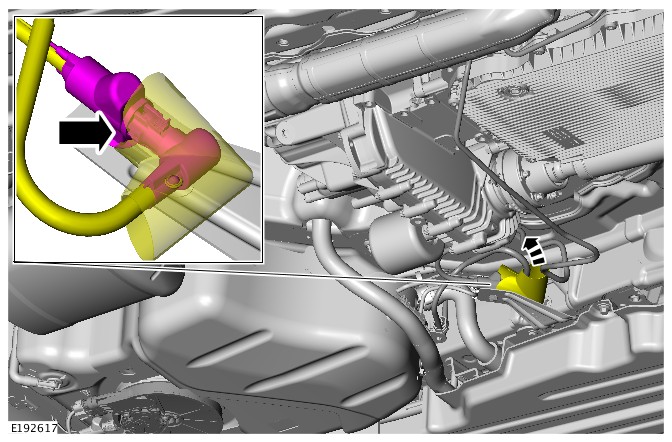


-
NOTES:
-
This step is only required if a new component is installed.
-
Diesel Exhaust Fluid (DEF) Tank comes as an assembly with DEF Injection Pump, if a new DEF Tank is installed make sure to configure the new DEF injection pump.
- Connect the Jaguar Land Rover (JLR) approved diagnostic equipment.
-
Select 'Powertrain - Diesel exhaust fluid injection pump replacement' from the diagnostic menu.
- Make sure that all steps from the on-screen instructions are followed.
-
- Fill the diesel exhaust fluid tank.
Refer to:Diesel Exhaust Fluid Tank Drain and Refill (303-08E Engine Emission Control - INGENIUM I4 2.0L Diesel, General Procedures).
ENGINE EMISSION CONTROL - TDV6 3.0L DIESEL /TDV6 3.0L DIESEL - GEN 1.5/TDV6 3.0L DIESEL - GEN 2
EXHAUST GAS RECIRCULATION COOLER FILTER (G2422281)
Injuries such as scalding can be caused by escaping steam or engine coolant, make sure the vehicle cooling system is cool prior to doing this procedure.
Be prepared to collect escaping engine coolant.
-
This procedure contains illustrations showing certain components removed to provide extra clarity.
-
Be prepared to collect escaping coolant.
-
This procedure contains information for the right and the left side Exhaust Gas Recirculation cooler filter.
- Raise and support the vehicle on a suitable 2 post lift.
Refer to:Lifting (100-02 Jacking and Lifting, Description and Operation).
- Remove the left Exhaust Gas Recirculation (EGR) valve and cooler assembly.
Refer to:Left Exhaust Gas Recirculation Valve - TDV6 3.0L Diesel /TDV6 3.0L Diesel - Gen 1.5 (303-08A Engine Emission Control - TDV6 3.0L Diesel /TDV6 3.0L Diesel - Gen 1.5/TDV6 3.0L Diesel - Gen 2, Removal and Installation).


- Install the left EGR valve and cooler assembly.
Refer to:Left Exhaust Gas Recirculation Valve - TDV6 3.0L Diesel /TDV6 3.0L Diesel - Gen 1.5 (303-08A Engine Emission Control - TDV6 3.0L Diesel /TDV6 3.0L Diesel - Gen 1.5/TDV6 3.0L Diesel - Gen 2, Removal and Installation
ENGINE EMISSION CONTROL - TDV6 3.0L DIESEL /TDV6 3.0L DIESEL - GEN 1.5/TDV6 3.0L DIESEL - GEN 2
RIGHT EXHAUST GAS RECIRCULATION VALVE (G1509511)
- 17.45.17
- VALVE - EGR - RH - RENEW
- 3000 CC, TDV6
- 1.30
- USED WITHINS
PART(S)
| STEP | PART NAME | QUANTITY |
|---|---|---|
| Removal Step 12 | EGR pipe to exhaust manifold gasket | 1 |
-
Removal steps in this procedure may contain installation details.
-
Some illustrations may show the engine removed for clarity.
-
Make sure that all openings are sealed.
-
Refer to:Specifications (414-00 Battery and Charging System - General Information, Specifications).
-
Refer to:Cooling System Partial Draining and Vacuum Filling (303-03F Engine Cooling - TDV8 4.4L Diesel, General Procedures).
-
Refer to:Secondary Bulkhead Center Panel - TDV6 3.0L Diesel /TDV6 3.0L Diesel - Gen 1.5/TDV6 3.0L Diesel - Gen 2 (501-02 Front End Body Panels, Removal and Installation).
-
Refer to:Right Exhaust Gas Recirculation Valve Outlet Tube (303-08A Engine Emission Control - TDV6 3.0L Diesel /TDV6 3.0L Diesel - Gen 1.5/TDV6 3.0L Diesel - Gen 2, Removal and Installation).
- To install reverse the removal procedure.
- If a new unit is installed, configure using the approved diagnostic tool.
ENGINE EMISSION CONTROL - TDV6 3.0L DIESEL /TDV6 3.0L DIESEL - GEN 1.5/TDV6 3.0L DIESEL - GEN 2
RIGHT EXHAUST GAS RECIRCULATION VALVE OUTLET TUBE (G1509513)
- 17.45.22
- TUBE - EGR VALVE OUTLET - RH - RENEW
- 3000 CC, TDV6
- 0.20
- USED WITHINS
PART(S)
| STEP | PART NAME | QUANTITY |
|---|---|---|
| Installation Step 1 | EGR pipe to exhaust manifold gasket | 1 |
| Installation Step 2 | Retaining clip(s) | 1 |
Some variation in the illustrations may occur, but the essential information is always correct.
-
Refer to:Engine Cover - TDV6 3.0L Diesel /TDV6 3.0L Diesel - Gen 1.5/TDV6 3.0L Diesel - Gen 2 (501-05 Interior Trim and Ornamentation, Removal and Installation).
-
Refer to:Engine Cover - TDV6 3.0L Diesel /TDV6 3.0L Diesel - Gen 1.5/TDV6 3.0L Diesel - Gen 2 (501-05 Interior Trim and Ornamentation, Removal and Installation).
ENGINE EMISSION CONTROL - TDV6 3.0L DIESEL /TDV6 3.0L DIESEL - GEN 1.5/TDV6 3.0L DIESEL - GEN 2
DIESEL EXHAUST FLUID INJECTOR (G1875977)
- 17.50.34
- DIESEL EXHAUST FLUID INJECTOR - RENEW
- 3000 CC, TDV6
- 0.40
- USED WITHINS
GENERAL EQUIPMENT
| EQUIPMENT NAME |
|---|
| Jaguar Land Rover approved diagnostic equipment |
PART(S)
| STEP | PART NAME | QUANTITY |
|---|---|---|
| Installation Step 1 | Diesel exhaust fluid injector refit kit | 1 |
Observe due care when working near a hot exhaust system.
Before disconnecting any components, make sure the area is clean and free from foreign material. When disconnected all openings must be sealed.
- This procedure contains some variation in the illustrations depending on the vehicle specification, but the essential information is always correct.
- This procedure contains illustrations showing certain components removed to provide extra clarity.
- Raise and support the vehicle on a suitable 2 post lift.
Refer to:Lifting (100-02 Jacking and Lifting, Description and Operation).
- Remove the engine undershield.
Refer to:Engine Undershield (501-02 Front End Body Panels, Removal and Installation).
-
- Install a new gasket to the DEF injector.
- Install the DEF injector.
- Install and tighten the clamp.
Torque: 5Nm
- Connect the DEF injector electrical connector.
- Connect the DEF injector supply pipe.
- Reposition the DEF injector supply pipe heatshield.
- Install the engine undershield.
Refer to:Engine Undershield (501-02 Front End Body Panels, Removal and Installation).
-
NOTE:
SRO to be claimed separately.
- Connect the Jaguar Land Rover (JLR) approved diagnostic equipment.
- Select 'Powertrain - Diesel Exhaust Fluid Prime and Pressure Test' from the diagnostic menu.
- Make sure that all steps from the on-screen instructions are followed.
ENGINE EMISSION CONTROL - TDV6 3.0L DIESEL /TDV6 3.0L DIESEL - GEN 1.5/TDV6 3.0L DIESEL - GEN 2
DIESEL EXHAUST FLUID PIPE (G1875980)
- 17.50.49
- PIPE - DIESEL EXHAUST FLUID INJECTOR FEED - RENEW
- 3000 CC, TDV6
- 1.30
- USED WITHINS
- This procedure contains some variation in the illustrations depending on the vehicle specification, but the essential information is always correct.
- This procedure contains illustrations showing certain components removed to provide extra clarity.
- Raise and support the vehicle on a suitable 2 post lift.
Refer to:Lifting (100-02 Jacking and Lifting, Description and Operation).
- Remove the Diesel Exhaust Fluid (DEF) tank.
Refer to:Diesel Exhaust Fluid Pipe (303-08A Engine Emission Control - TDV6 3.0L Diesel /TDV6 3.0L Diesel - Gen 1.5/TDV6 3.0L Diesel - Gen 2, Removal and Installation).
- Install the Diesel Exhaust Fluid (DEF) pipe.
- Install the DEF tank.
Refer to:Diesel Exhaust Fluid Pipe (303-08A Engine Emission Control - TDV6 3.0L Diesel /TDV6 3.0L Diesel - Gen 1.5/TDV6 3.0L Diesel - Gen 2, Removal and Installation).
ENGINE EMISSION CONTROL - TDV6 3.0L DIESEL /TDV6 3.0L DIESEL - GEN 1.5/TDV6 3.0L DIESEL - GEN 2
LEFT EXHAUST GAS RECIRCULATION VALVE - TDV6 3.0L DIESEL /TDV6 3.0L DIESEL - GEN 1.5 (G1509510)
- 17.45.16
- VALVE - EGR - LH - RENEW
- 3000 CC, TDV6, WITH PARTICULATE FILTER, WITH DIESEL EXHAUST FLUID
- 1.30
- USED WITHINS
PART(S)
| STEP | PART NAME | QUANTITY |
|---|---|---|
| Removal Step 11 | Exhaust gas recirculation gasket | 1 |
-
Removal steps in this procedure may contain installation details.
-
Some illustrations may show the engine removed for clarity.
-
Make sure that all openings are sealed.
-
Refer to:Specifications (414-00 Battery and Charging System - General Information, Specifications).
-
Refer to:Cooling System Partial Draining and Vacuum Filling (303-03F Engine Cooling - TDV8 4.4L Diesel, General Procedures).
-
Refer to:Secondary Bulkhead Center Panel - TDV6 3.0L Diesel /TDV6 3.0L Diesel - Gen 1.5/TDV6 3.0L Diesel - Gen 2 (501-02 Front End Body Panels, Removal and Installation).
-
Refer to:Left Exhaust Gas Recirculation Valve Outlet Tube - TDV6 3.0L Diesel - Gen 1.5 (303-08A Engine Emission Control - TDV6 3.0L Diesel /TDV6 3.0L Diesel - Gen 1.5/TDV6 3.0L Diesel - Gen 2, Removal and Installation).
- To install reverse the removal procedure.
- If a new unit is installed, configure using the approved diagnostic tool.
ENGINE EMISSION CONTROL - TDV6 3.0L DIESEL /TDV6 3.0L DIESEL - GEN 1.5/TDV6 3.0L DIESEL - GEN 2
DIESEL EXHAUST FLUID INJECTION PUMP (G1937878)
- 17.50.35
- DIESEL EXHAUST FLUID INJECTION PUMP - RENEW
- ALL DERIVATIVES
- 0.70
- USED WITHINS
GENERAL EQUIPMENT
| EQUIPMENT NAME |
|---|
| Jaguar Land Rover approved diagnostic equipment |
PART(S)
| STEP | PART NAME | QUANTITY |
|---|---|---|
| Installation Step 1 | Diesel exhaust fluid injection pump seals | 1 |
| Installation Step 3 | Sleeve and isolator assemblies | 1 |
| Installation Step 4 | Diesel exhaust fluid injection pump bolts | 1 |
-
Some variation in the illustrations may occur, but the essential information is always correct.
-
Some components shown removed for clarity.
-
Raise and support the vehicle.WARNING:
Make sure to support the vehicle with axle stands.
-
Refer to:Diesel Exhaust Fluid Tank Drain and Refill (303-08A Engine Emission Control - TDV6 3.0L Diesel /TDV6 3.0L Diesel - Gen 1.5/TDV6 3.0L Diesel - Gen 2, General Procedures).
-
NOTE:
This step is only required if a new component is installed.
- Connect the Jaguar Land Rover (JLR) approved diagnostic equipment.
General Equipment: Jaguar Land Rover approved diagnostic equipment
- Select 'Powertrain - Diesel exhaust fluid injection pump replacement' from the diagnostic menu.
- Make sure that all steps from the on-screen instructions are followed.
- Connect the Jaguar Land Rover (JLR) approved diagnostic equipment.
-
Refer to:Diesel Exhaust Fluid Tank Drain and Refill (303-08A Engine Emission Control - TDV6 3.0L Diesel /TDV6 3.0L Diesel - Gen 1.5/TDV6 3.0L Diesel - Gen 2, General Procedures).
ENGINE EMISSION CONTROL - TDV6 3.0L DIESEL /TDV6 3.0L DIESEL - GEN 1.5/TDV6 3.0L DIESEL - GEN 2
DIESEL EXHAUST FLUID TANK (G1958061)
- 17.50.36
- DIESEL EXHAUST FLUID TANK - RENEW
- 3000 CC, TDV6
- 0.80
- USED WITHINS
GENERAL EQUIPMENT
| EQUIPMENT NAME |
|---|
| Jaguar Land Rover approved diagnostic equipment |
- Some variation in the illustrations may occur, but the essential information is always correct.
- Some components shown removed for clarity.
-
Raise and support the vehicle.WARNING:
Make sure to support the vehicle with axle stands.
- Drain the diesel exhaust fluid tank.
Refer to:Diesel Exhaust Fluid Tank Drain and Refill (303-08E Engine Emission Control - INGENIUM I4 2.0L Diesel, General Procedures).
-
NOTES:
-
This step is only required if a new component is installed.
-
Diesel Exhaust Fluid (DEF) Tank comes as an assembly with DEF Injection Pump, if a new DEF Tank is installed make sure to configure the new DEF injection pump.
- Connect the Jaguar Land Rover (JLR) approved diagnostic equipment.
- Select 'Powertrain - Diesel exhaust fluid injection pump replacement' from the diagnostic menu.
- Make sure that all steps from the on-screen instructions are followed.
-
- Fill the diesel exhaust fluid tank.
Refer to:Diesel Exhaust Fluid Tank Drain and Refill (303-08E Engine Emission Control - INGENIUM I4 2.0L Diesel, General Procedures).
ENGINE EMISSION CONTROL - TDV6 3.0L DIESEL /TDV6 3.0L DIESEL - GEN 1.5/TDV6 3.0L DIESEL - GEN 2
EXHAUST GAS RECIRCULATION COOLER FILTER (G2422281)
Injuries such as scalding can be caused by escaping steam or engine coolant, make sure the vehicle cooling system is cool prior to doing this procedure.
Be prepared to collect escaping engine coolant.
-
This procedure contains illustrations showing certain components removed to provide extra clarity.
-
Be prepared to collect escaping coolant.
-
This procedure contains information for the right and the left side Exhaust Gas Recirculation cooler filter.
- Raise and support the vehicle on a suitable 2 post lift.
Refer to:Lifting (100-02 Jacking and Lifting, Description and Operation).
- Remove the left Exhaust Gas Recirculation (EGR) valve and cooler assembly.
Refer to:Left Exhaust Gas Recirculation Valve - TDV6 3.0L Diesel /TDV6 3.0L Diesel - Gen 1.5 (303-08A Engine Emission Control - TDV6 3.0L Diesel /TDV6 3.0L Diesel - Gen 1.5/TDV6 3.0L Diesel - Gen 2, Removal and Installation).
- Install the left EGR valve and cooler assembly.
Refer to:Left Exhaust Gas Recirculation Valve - TDV6 3.0L Diesel /TDV6 3.0L Diesel - Gen 1.5 (303-08A Engine Emission Control - TDV6 3.0L Diesel /TDV6 3.0L Diesel - Gen 1.5/TDV6 3.0L Diesel - Gen 2, Removal and Installation).
303-12A: Intake Air Distribution and Filtering - TDV6 3.0L Diesel /TDV6 3.0L Diesel - Gen 1.5/TDV6 3.0L Diesel - Gen 2
INTAKE AIR DISTRIBUTION AND FILTERING - TDV6 3.0L DIESEL /TDV6 3.0L DIESEL - GEN 1.5/TDV6 3.0L DIESEL - GEN 2 (G1509519)
Torque Specification
| DESCRIPTION | NM | LB-FT | LB-IN |
|---|---|---|---|
| Air cleaner outlet pipe clip | 3.5 | - | 31 |
| *Charge air cooler torx bolt | 9 | 7 | - |
| Charge air cooler M6 | 5 | 4 | - |
| Charge air cooler nut | 9 | 7 | - |
| Charge air cooler inlet pipe clip | 5 | - | 44 |
| Charge air cooler outlet pipe clip | 5 | - | 44 |
* A new nut must be installed.
Description and OperationINTAKE AIR DISTRIBUTION AND FILTERING - TDV6 3.0L DIESEL /TDV6 3.0L DIESEL - GEN 1.5/TDV6 3.0L DIESEL - GEN 2 (G1868450)
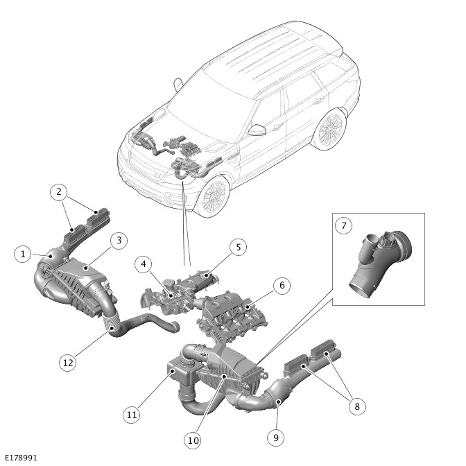
| ITEM | DESCRIPTION |
|---|---|
| 1 | Right dirty air duct (if fitted) |
| 2 | Right intake grilles (if fitted) |
| 3 | Right air cleaner (if fitted) |
| 4 | Electric throttle |
| 5 | Right intake manifold (integral with camshaft cover) |
| 6 | Left intake manifold (integral with camshaft cover) |
| 7 | EGR pipe (if fitted) |
| 8 | Left intake grilles |
| 9 | Left dirty air duct |
| 10 | Left air cleaner |
| 11 | Left clean air ducts with resonator |
| 12 | Right clean air ducts |

| ITEM | DESCRIPTION |
|---|---|
| 1 | Charge air duct – charge air intake valve to left clean air duct |
| 2 | Charge air ducts – secondary turbocharger to charge air intake valve |
| 3 | Charge air ducts – charge air cooler to electric throttle |
| 4 | Secondary turbocharger |
| 5 | Primary turbocharger |
| 6 | Charge air ducts – primary turbocharger to charge air cooler |
| 7 | Charge air cooler |
| 8 | Charge air ducts – charge air intake valve to charger air cooler |
| 9 | Charge air intake valve |

| ITEM | DESCRIPTION |
|---|---|
| 1 | Charge air ducts – charge air cooler to electric throttle |
| 2 | Turbocharger |
| 3 | Charge air cooler |
| 4 | Charge air ducts – turbocharger to charge air cooler |
The intake air distribution and filtering system cleans, compresses and cools the intake air. The system comprises according to bi- or mono-turbo variant is equipped:
| Bi-turbo engines | Mono-turbo engines |
| Two dirty air ducts. | A dirty air duct. |
| Two air cleaners. | An air cleaner. |
| Two clean air ducts, one with resonator. | A clean air duct with resonator. |
| Two turbochargers. | A turbocharger. |
| Charge air ducts. | A charge air duct. |
| A charge air intake valve. | - |
| A water cooled charge air cooler. | A water cooled charge air cooler. |
| An electric throttle. | An electric throttle. |
| Two intake manifolds. | Two intake manifolds. |
| A low pressure EGR duct | A low pressure EGR duct |
Air flows through the dirty air ducts, air cleaners and clean air ducts to the compressor intakes of the turbochargers. The turbochargers compress the air, which is then transferred through the charge air ducts to the charge air intake valve, charge air cooler, electric throttle and the intake manifolds.
DIRTY AIR DUCTS

| ITEM | DESCRIPTION |
|---|---|
| 1 | Front fender support |
| 2 | Screw |
| 3 | Intake grille |
| 4 | Screw |
| 5 | Intake grille |
| 6 | Front upper bracket |
| 7 | Front lower bracket |
| 8 | Non-porous sleeve |
The dirty air ducts are installed in the front fenders to transfer ambient air from under the edges of the hood to the air cleaners. If mono-turbo variant is equipped one air duct is fitted on the left side.
Each dirty air duct locates in the intake of the related air cleaner and is attached to the front inner fender with two brackets. The intake of each dirty air duct is attached to two intake grilles on top of the front fender support. When the hood is closed, the intake grilles locate in guides attached to the hood inner panel.
A porous section, covered by a non-porous sleeve to prevent moisture ingress, is incorporated into each dirty air duct to reduce induction noise.
AIR CLEANERS

| ITEM | DESCRIPTION |
|---|---|
| 1 | Screw (6 off) |
| 2 | Lid |
| 3 | Isolators |
| 4 | Air intake |
| 5 | Drain valve |
| 6 | Isolator |
| 7 | Base |
| 8 | Engine vacuum system connection (left air cleaner only) |
| 9 | Air outlet |
| 10 | Mass Air Flow (MAF) sensor (left air cleaner) or Mass Air Flow and Temperature (MAFT) sensor (right air cleaner) |
An air cleaner is located in each front corner of the engine compartment if bi-turbo variant is equipped and one air cleaner is located in the left front corner of the engine compartment if mono-turbo variant is equipped. Three spigots fitted with isolator bushes locate each air cleaner in holes in the related front inner fender and front suspension housing.
Each air cleaner consists of a filter element installed in a base and enclosed with a lid secured by six screws. The filter element is a pleated, paper type with an integral seal. Air intake and outlet connections are incorporated into the base and lid respectively. The bottom of the base incorporates a drain valve to prevent the accumulation of water in the air cleaner.
The lid of the left air cleaner incorporates a connection for the engine vacuum system. For additional information, refer to:
The air outlet connection of each air cleaner incorporates either a mass air flow (MAF) sensor (right air cleaner, if equipped) and a mass air flow and temperature (MAFT) sensor (left air cleaner). If mono-tubro variant if equipped only a MAFT sensors is fitted. The sensors are connected to the Engine Control module (ECM). For additional information, refer to:Electronic Engine Controls (303-14A Electronic Engine Controls - TDV6 3.0L Diesel /TDV6 3.0L Diesel - Gen 1.5/TDV6 3.0L Diesel - Gen 2, Description and Operation).
CLEAN AIR DUCTS

| ITEM | DESCRIPTION |
|---|---|
| 1 | Air intake - twin-turbo variant only |
| 2 | Convolute - twin-turbo variant only |
| 3 | Bracket - twin-turbo variant only |
| 4 | Air outlet - twin-turbo variant only |
| 5 | Air intake |
| 6 | Convolute |
| 7 | Resonator |
| 8 | Air outlet |
| 9 | Bracket |
| 10 | Charge air bypass hose connection |
The clean air ducts transfer air from the air cleaner outlets to the compressor intakes on the turbochargers. Each clean air duct incorporates a convolute section to accommodate relative movement between the engine mounted turbochargers and the body mounted air cleaners. The left clean air duct also incorporates a quarter wave resonator to reduce air induction noise.
If bi-turbo variant is fitted the left clean air duct also incorporates connection for the bypass hose from the charge air intake valve.For additional information, refer to:Turbocharger (303-04B Fuel Charging and Controls - Turbocharger - TDV6 3.0L Diesel, Description and Operation).
Brackets on the clean air ducts attach the ducts to the A/C compressor (left air duct) and the generator mounting bracket (right clean air duct, if equipped).
TURBOCHARGERS
The turbochargers are attached to the exhaust manifolds. A VGT (variable geometry turbine) turbocharger, designated as the primary turbocharger, is located on the left side of the engine. A fixed vane turbocharger, designated as the secondary turbocharger, is installed on the right side of the engine.For additional information, refer to:Turbocharger (303-04B Fuel Charging and Controls - Turbocharger - TDV6 3.0L Diesel, Description and Operation).
CHARGE AIR DUCTS

| ITEM | DESCRIPTION |
|---|---|
| 1 | Secondary turbocharger air tube connection |
| 2 | Charge air temperature sensor |
| 3 | Secondary turbocharger charge air pressure connection |

| ITEM | DESCRIPTION |
|---|---|
| 1 | Secondary turbocharger air tube connection |
| 2 | Charge air temperature sensor |
The charge air ducts interconnect the turbocharger compressor outlets, charge air intake valve (if bi-turbo variant is equipped), charge air cooler and electric throttle.
The charge air duct connection with the electric throttle incorporates connections for:
- An air tube connected to the secondary turbocharger. For additional information, refer to:Turbocharger (303-04B Fuel Charging and Controls - Turbocharger - TDV6 3.0L Diesel, Description and Operation).
- A charge air temperature sensor connected to the ECM.For additional information, refer to:Electronic Engine Controls (303-14A Electronic Engine Controls - TDV6 3.0L Diesel /TDV6 3.0L Diesel - Gen 1.5/TDV6 3.0L Diesel - Gen 2, Description and Operation).
The charge air duct connected to the outlet of the secondary turbocharger incorporates a connection for the charge air pressure sensor.For additional information, refer to:Electronic Engine Controls (303-14A Electronic Engine Controls - TDV6 3.0L Diesel /TDV6 3.0L Diesel - Gen 1.5/TDV6 3.0L Diesel - Gen 2, Description and Operation).
CHARGE AIR INTAKE VALVE - ONLY FOR BI-TURBO VARIANT
The charge air intake valve is attached to a bracket on the front subframe and the cooling pack protector.
The charge air intake valve is used by the ECM to change turbocharger operation between mono and bi-turbo modes. The valve controls the flow of air from the compressor of the secondary turbocharger to the clean air duct of the primary turbocharger and to the charge air cooler.For additional information, refer to:Turbocharger (303-04B Fuel Charging and Controls - Turbocharger - TDV6 3.0L Diesel, Description and Operation).
CHARGE AIR COOLERS

| ITEM | DESCRIPTION |
|---|---|
| 1 | Isolator bush |
| 2 | Air intake |
| 3 | Isolator bush |
| 4 | Front air duct |
| 5 | Rear air duct |
| 6 | Charge air cooler |
| 7 | Cooling water connection |
| 8 | Isolator |
| 9 | Air outlet |
| 10 | Isolator |
| 11 | Cooling water connection |
The charge air cooler is a water cooled charge air cooler that reduce the intake air temperature.
A charge air cooler is installed on the left side of the cooling pack, behind the left outer air intake in the front bumper. The charge air cooler is installed in air duct attached to the front bumper armature and the front end carrier. The lower end tank of the charge air cooler is located in the air ducts by two spigots fitted with isolator bushes. The upper end tank of each charge air cooler is attached to the front end carrier and the air ducts with two isolator bushes, nuts and bolts.
ELECTRIC THROTTLE

| ITEM | DESCRIPTION |
|---|---|
| 1 | Air intake |
| 2 | Electric motor |
| 3 | Right Exhaust Gas Recirculation (EGR) pipe connection |
| 4 | Right intake manifold connection |
| 5 | Manifold Absolute Pressure (MAP) sensor |
| 6 | Left intake manifold connection |
| 7 | Left EGR pipe connection |
The electric throttle regulates the air flow from the charge air coolers to the intake manifolds.
The electric throttle is installed at the front of the engine, between the cylinder heads. Two outlets on the electric throttle locate in the two intake manifolds. A stud bolt attaches the electric throttle to the right cylinder head.
The throttle plate is operated by a DC (Direct Current) electric motor attached to the throttle body. The motor is controlled by the ECM and is constantly adjusted the throttle according to the EGR valve opening, and in response to driver inputs with the throttle pedal, to control the amount of air allowed into the intake manifolds.For additional information, refer to:Electronic Engine Controls (303-14A Electronic Engine Controls - TDV6 3.0L Diesel /TDV6 3.0L Diesel - Gen 1.5/TDV6 3.0L Diesel - Gen 2, Description and Operation).
Pipe connections on both sides of the throttle body allow for the attachment of the outlet pipes from the Exhaust Gas Recirculation (EGR) valves. The pipe attachments in the throttle body are specifically designed to mix the recirculated exhaust gas with the intake air and provide an even distribution to each side of the engine.
A manifold absolute pressure (MAP) sensor is located in the top of the throttle body where the air flow splits for the two intake manifolds.For additional information, refer to:Electronic Engine Controls (303-14A Electronic Engine Controls - TDV6 3.0L Diesel /TDV6 3.0L Diesel - Gen 1.5/TDV6 3.0L Diesel - Gen 2, Description and Operation).
INTAKE MANIFOLDS
The intake manifolds are an integral part of the camshaft covers. Each intake manifold is connected to the electric throttle by a push fit, sealed connection.For additional information, refer to:Engine (303-01A Engine - TDV6 3.0L Diesel /TDV6 3.0L Diesel - Gen 1.5/TDV6 3.0L Diesel - Gen 2, Description and Operation).
Diagnosis and TestingNTAKE AIR DISTRIBUTION AND FILTERING - TDV6 3.0L DIESEL /TDV6 3.0L DIESEL - GEN 1.5/TDV6 3.0L DIESEL - GEN 2 (G2718601)
For a detailed description of the intake air distribution and filtering system and operation, refer to the relevant Description and Operation section of the workshop manual. REFER to:Intake Air Distribution and Filtering (303-12A Intake Air Distribution and Filtering - TDV6 3.0L Diesel /TDV6 3.0L Diesel - Gen 1.5/TDV6 3.0L Diesel - Gen 2, Description and Operation).
Diagnosis by substitution from a donor vehicle is NOT acceptable. Substitution of control modules does not guarantee confirmation of a fault and may also cause additional faults in the vehicle being checked and/or the donor vehicle.
Check and rectify basic faults before beginning diagnostic routines involving pinpoint tests.
- Verify the customer concern.
- Visually inspect for obvious signs of mechanical or electrical damage.
Visual Inspection
| MECHANICAL | ELECTRICAL |
|---|---|
|
|
- If an obvious cause for an observed or reported concern is found, correct the cause (if possible) before proceeding to the next step.
- If the cause is not visually evident, verify the symptom and refer to the Symptom Chart, alternatively check for Diagnostic Trouble Code(s) (DTC)s and refer to the DTC Index.
| SYMPTOM | POSSIBLE CAUSES | ACTION |
|---|---|---|
| Vehicle does not start/hard starting |
|
|
| Poor performance |
|
|
| Excessive intake noise |
|
|
Affected Vehicle Range
| MODEL: | MODEL YEAR: | VEHICLE IDENTIFICATION NUMBER (VIN): | ASSEMBLY PLANT: | APPLICABILITY: |
|---|---|---|---|---|
| Range Rover (LG) | 2015-2018 | 202850-510666 | Solihull | TDV6 3.0L Diesel - Gen 2 |
| Discovery (LR) | 2017-2018 | 000001-075312 | Solihull | TDV6 3.0L Diesel |
| Range Rover Sport (LW) | 2016-2018 | 100003-199996 | Solihull | TDV6 3.0L Diesel - Gen 2 |
| Range Rover Sport (LW) | 2015-2016 | 512861-599999 | Solihull | TDV6 3.0L Diesel - Gen 2 |
| Range Rover Sport (LW) | 2018 | 400291-413163 | Solihull | TDV6 3.0L Diesel - Gen 2 |
| Range Rover Sport (LW) | 2015-2018 | 600440-699492 | Solihull | TDV6 3.0L Diesel - Gen 2 |
| Range Rover Sport (LW) | 2018 | 800000-808712 | Solihull | TDV6 3.0L Diesel - Gen 2 |
A customer may express a concern of restricted performance accompanied by an illuminated Malfunction Indicator Lamp on the Instrument Cluster (IC), with DTC P0299-77 stored in the Powertrain Control Module (PCM).
Charge air cooler hose collapsing internally.
Should a customer express this concern, follow the service instruction below.
| DESCRIPTION | QUANTITY |
|---|---|
| Charge air cooler hose | 1 |
2017 Onwards Model Year (MY) vehicles
This procedure requires a minimum of Pathfinder 190 loaded or later.
-
The Jaguar Land Rover (JLR) approved diagnostic equipment will read the VIN for the vehicle and automatically take the vehicle out of ‘Transportation mode’ if required.
-
DTC P0299-77 can be set for multiple reasons, work through all required checks against this DTC before determining the charge air cooler hose requires renewal.
- Connect the JLR approved battery support unit.
- Connect the JLR approved diagnostic equipment to the vehicle and begin a new session.
- Follow the JLR approved diagnostic equipment prompts.
- Select 'ECU Diagnostics'.
- Select 'All DTCs'.
- If DTC P0299-77 is present, continue to the service instruction.
- If DTC P0299-77 is not present, do not continue with this bulletin and continue diagnosis using TOPIx Worksop Manual section 100-00: General Information - Diagnostic Trouble Code Index.
- Select 'Clear all DTCs'.
- Follow all on-screen instructions to complete this task.
- When all of the tasks are complete, exit the current session.
- Disconnect the JLR approved diagnostic equipment and the JLR approved battery support unit.
-
This procedure contains some variation in the illustrations depending on the vehicle specification, but the essential information is always correct.
-
This procedure contains illustrations showing certain components removed to provide extra clarity.
-
DTC P0299-77 can be set for multiple reasons, work through all required checks against this DTC before determining the charge air cooler hose requires renewal.
- Check the vehicle for an excessive engine oil level.
- If an excessive engine oil level is discovered, rectify the oil level using TOPIx repair procedures, recheck the vehicle and submit a separate warranty claim.
- If the oil level is ok, go to the next step.
- Check for excessive oil within the air induction system.
- If excessive levels of oil are discovered within the induction system, investigate and rectify using TOPIx repair procedures, recheck the vehicle and submit a separate warranty claim.
- If no excessive oil is detected, go to the next step.
- Check the vehicles exhaust system for leakage.
- If an exhaust system leak is discovered, please correct the leak using TOPIx repair procedures, recheck the vehicle and submit a separate warranty claim.
- If no exhaust leak is discovered, go to the next step.
- Check the charge air pressure sensor for signs of blockage.
- If the charge air sensor is found to be blocked, rectify the blocked sensor using TOPIx repair procedures, recheck the vehicle and submit a separate warranty claim.
- If the charge pressure sensor is ok, go to the next step.
- Check the turbocharger system/vanes mechanical integrity.
- If the turbocharger appears to be faulty, investigate and rectify using TOPIx repair procedures, recheck the vehicle and submit a separate warranty claim.
- If the turbocharger is ok, go to the next step.
- Complete a leakage test on the vehicles induction system, (see TOPIx Workshop Manual - 303-00: Engine System - General Information - General Procedures - Leakage Test Using Smoke Test Equipment).
- If a leak has been detected do not continue with this technical bulletin, please correct the leak using TOPIx repair procedures, retest the vehicle and submit a separate warranty claim.
- If no leak has been detected, go to step 7.
- Replace the charge air cooler hose, refer to steps 8 - 13.
- Remove the engine cover (See TOPIx workshop manual section: 501-05 Interior Trim and Ornamentation - Removal and Installation - Engine Cover - TDV6 3.0L Diesel - Gen 2/TDV6 3.0L Diesel /TDV6 3.0L Diesel - Gen 1.5).
- For Range Rover and Range Rover Sport vehicles, go to step 9.
- For Discovery vehicles, go to step 10.
- Remove the engine compartment front trim covers.
- Remove fasteners and lift both outer covers upwards.
- Pull the center trim upwards for removal.
Some components are removed for clarity.
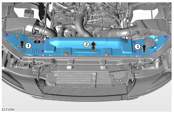
- Remove the engine compartment front trim covers.
- Remove fasteners and lift both outer covers upwards.
- Remove fasteners and lift the center cover upwards.
Some components are removed for clarity.
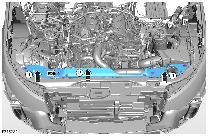
- Disconnect the vacuum pipe and the electrical connector from the charge air cooler hose, release the securing clip and disconnect the charge air cooler hose from the electronic throttle body, disconnect the charge air cooler hose from the top of the charge air cooler.
Some components are removed for clarity.

- Renew the charge air cooler hose.
- Repeat steps 11 - 8 in reverse to complete the operation.
For a list of DTCs that could be set on this vehicle, please refer to Section 100-00. REFER to:Diagnostic Trouble Code Index - TDV6 3.0L Diesel /TDV6 3.0L Diesel - Gen 1.5/TDV6 3.0L Diesel - Gen 2, DTC: Powertrain Control Module B10A2-07 to P02D7-32 (100-00 General Information, Description and Operation).
General ProceduresINTAKE AIR DISTRIBUTION AND FILTERING - TDV6 3.0L DIESEL /TDV6 3.0L DIESEL - GEN 1.5/TDV6 3.0L DIESEL - GEN 2
LEAKAGE TEST USING SMOKE TEST EQUIPMENT (G2374824)
- 01.01.28
- LEAKAGE TEST USING SMOKE TEST EQUIPMENT
- 3000 CC, TDV6
- 0.40
- USED WITHINS
SPECIAL TOOL(S)

JLR-303-1704-1
Blanking Plug for (Diesel) Air Intake Systems
GENERAL EQUIPMENT
| EQUIPMENT NAME |
|---|
| Adapter - High Pressure Diagnostic Leak Detector |
| High Pressure Diagnostic Leak Detector |
- Do not exceed 0.35 bar (5 psi, 34.5 kPA) test pressure, when testing the engine intake system.
- Only use calibrated equipment recommended by Jaguar Land Rover.
- This procedure contains some variation in the illustrations depending on the vehicle specification, but the essential information is always correct.
- This procedure contains illustrations showing certain components removed to provide extra clarity.
- Remove the engine cover.
Refer to:Engine Cover - TDV6 3.0L Diesel /TDV6 3.0L Diesel - Gen 1.5/TDV6 3.0L Diesel - Gen 2 (501-05 Interior Trim and Ornamentation, Removal and Installation).

-
NOTE:
Make sure the adapter is a good fit to the clean air duct. This must be an air tight seal.
Insert the appropriate adaptor into the clean air duct.General Equipment: Adapter - High Pressure Diagnostic Leak DetectorTorque: 3.5Nm


-
-
Insert the appropriate adaptor into the air filter outlet pipe.NOTE:
Make sure the adapter is a good fit to the clean air duct. This must be an air tight seal.
General Equipment: Adapter - High Pressure Diagnostic Leak Detector
- Tighten the hose clamp.
Torque: 3.5Nm
-


-
Install the special tool into the breather hose.Install the Special Tool(s): JLR-303-1704-1

-
CAUTION:
Never use dye/UV dye in intake or exhaust systems because it may coat or harm critical sensors.
NOTES:-
Only use Jaguar Land rover (JLR) approved vapor producing fluid.
-
60 ml maximum to refill the vapor producing fluid when the reservoir is empty.
- Check the high pressure diagnostic leak detector vapor producing fluid level. Top up if required.
-
-
CAUTION:
Never use dye/UV dye in intake or exhaust systems. Failure to follow this instruction may coat or harm critical sensors.
Check the high pressure diagnostic leak detector vapor producing fluid level. Top up if required.NOTES:-
Only use Jaguar Land rover (JLR) approved vapor producing fluid.
-
60 ml maximum to refill the vapor producing fluid when the reservoir is empty.
-
-
Connect the high pressure diagnostic leak detector to a suitable power supply.CAUTIONS:
-
Do not connect the high pressure diagnostic leak detector to a battery charger, battery support unit or jumper box.
-
Never connect the high pressure diagnostic leak detector to the vehicle with the engine running.
-
- Connect the high pressure diagnostic leak detector to a suitable air supply.


-
- Connect the high pressure diagnostic leak detector outlet pipe to the adaptor.
General Equipment: High Pressure Diagnostic Leak Detector
- Connect the high pressure diagnostic leak detector outlet pipe to the adaptor.


-
- Use the inspection light supplied with the high pressure diagnostic leak detector, to inspect for leaks.
- If a leak is detected, rectify the cause.
-
- Disconnect the high pressure diagnostic leak detector from the power supply.
- Disconnect the high pressure diagnostic leak detector from the air supply.
- Disconnect the high pressure diagnostic leak detector from the adaptor.
- Remove the special tool from the breather hose.
Remove the Special Tool(s): JLR-303-1704-1
- Install the breather hose.
- Remove the adaptor from the left air filter outlet pipe.
-
- Install the left air filter outlet pipe.
- Tighten the hose clamp.
Torque: 3.5Nm
- Remove the block off adaptor.
- Remove the adaptor from the right air filter outlet pipe.
-
- Install the right air filter outlet pipe.
- Tighten the hose clamp.
Torque: 3.5Nm
- Install the engine cover.
Refer to:Engine Cover - TDV6 3.0L Diesel /TDV6 3.0L Diesel - Gen 1.5/TDV6 3.0L Diesel - Gen 2 (501-05 Interior Trim and Ornamentation, Removal and Installation).
INTAKE AIR DISTRIBUTION AND FILTERING - TDV6 3.0L DIESEL /TDV6 3.0L DIESEL - GEN 1.5/TDV6 3.0L DIESEL - GEN 2
AIR CLEANER ELEMENT (G1509521)
- 19.10.10
- AIR FILTER ELEMENT - RENEW
- 3000 CC, TDV6
- 0.10
- USED WITHINS


- To install, reverse the removal procedure.
INTAKE AIR DISTRIBUTION AND FILTERING - TDV6 3.0L DIESEL /TDV6 3.0L DIESEL - GEN 1.5/TDV6 3.0L DIESEL - GEN 2
LEFT AIR CLEANER (G1519884)
- 19.10.03
- AIR CLEANER - LH - RENEW
- 3000 CC, TDV6
- 0.30
- USED WITHINS
Removal steps in this procedure may contain installation details.


- To install, reverse the removal procedure.
NTAKE AIR DISTRIBUTION AND FILTERING - TDV6 3.0L DIESEL /TDV6 3.0L DIESEL - GEN 1.5/TDV6 3.0L DIESEL - GEN 2
RIGHT AIR CLEANER (G1519885)
- 19.10.04
- AIR CLEANER - RH - RENEW
- 3000 CC, TDV6
- 0.30
- USED WITHINS
Removal steps in this procedure may contain installation details.

- Do not disassemble further if the component is removed for access only.
- To install, reverse the removal procedure.
INTAKE AIR DISTRIBUTION AND FILTERING - TDV6 3.0L DIESEL /TDV6 3.0L DIESEL - GEN 1.5/TDV6 3.0L DIESEL - GEN 2
LEFT CHARGE AIR COOLER - TDV6 3.0L DIESEL - GEN 2 (G1875612)
- 19.44.02
- INTERCOOLER - LH - RENEW
- 3000 CC, TDV6, GEN 2
- 1.70
- USED WITHINS
PART(S)
| STEP | PART NAME | QUANTITY |
|---|---|---|
| Removal Step 4 | Retaining clip | 1 |
| Removal Step 9 | Retaining clip | 1 |
-
Some variation in the illustrations may occur, but the essential information is always correct.
-
Removal steps in this procedure may contain installation details.
-
Refer to:Cooling System Draining and Vacuum Filling (303-03A Engine Cooling - TDV6 3.0L Diesel /TDV6 3.0L Diesel - Gen 1.5/TDV6 3.0L Diesel - Gen 2, General Procedures).
-
Refer to:Front Bumper Cover (501-19 Bumpers, Removal and Installation).


- To install, reverse the removal procedure.
303-14A: Electronic Engine Controls - TDV6 3.0L Diesel /TDV6 3.0L Diesel - Gen 1.5/TDV6 3.0L Diesel - Gen 2
ELECTRONIC ENGINE CONTROLS - TDV6 3.0L DIESEL /TDV6 3.0L DIESEL - GEN 1.5/TDV6 3.0L DIESEL - GEN 2 (G1509550)
Torque Specification