Range Rover Sport / L494 2017 GENERAL ENGINE INFORMATION ALL ENGINES USER MANUAL
ENGINE SYSTEM - GENERAL INFORMATION
Range Rover Sport / L494 2017 User Manual GENERAL ENGINE INFORMATION ALL ENGINES
ENGINE - TDV6 3.0L DIESEL (G1883208)
For a detailed description of the 3.0L Diesel engine, refer to the relevant Description and Operation section in the workshop manual. REFER to:Engine (303-01A Engine - TDV6 3.0L Diesel /TDV6 3.0L Diesel - Gen 1.5/TDV6 3.0L Diesel - Gen 2, Diagnosis and Testing).
- Verify the customer concern.
- Visually inspect for obvious signs of mechanical or electrical damage.
Visual Inspection
| MECHANICAL | ELECTRICAL |
|---|---|
|
|
- If an obvious cause for an observed or reported concern is found, correct the cause (if possible) before proceeding to the next step.
- If the concern is not visually evident, verify the symptom and refer to the relevant Symptom Chart. Symptom Charts have been separated into Leaks and Noise, Vibration and Harshness (NVH) for ease of use. Alternatively, check for Diagnostic Trouble Codes (Diagnostic trouble code(s)) and refer to the relevantDiagnostic Trouble Code(s) (DTC) Index.
Symptom Chart, Leaks
| SYMPTOM | POSSIBLE CAUSE | ACTION |
|---|---|---|
| External coolant leaks |
|
|
| Internal coolant leaks Note: This may be indicated by the production of white smoke from the exhaust |
|
|
| Engine overheats |
|
|
| Engine takes too long to reach operating temperature |
|
|
| External oil leaks |
|
NOTE:
Do not assume where oil is visible on the engine that is the source of the oil leak. For example, oil may be visible around the sump gasket, but the source of the leak is likely to be from a gasket or seal higher up on the engine. Always check for other leaking components before condemning the sump gasket.
|
| Internal oil leaks (leaks into coolant or combustion chamber) Note: This may be indicated by the production of blue smoke from the exhaust |
|
|
Symptom ChartNVH
-
Where possible please complete a back to back test with a similar specification vehicle to confirm the issue in not a characteristic of the engine.
-
As the checks suggested here are open to interpretation, they should be used as a guide only. Descriptions of noises, etc, are in general terms, so depend on a degree of experience on the part of the technician.
| SYMPTOM | POSSIBLE CAUSE | ACTION |
|---|---|---|
| Rattle/ticking from top of engine |
|
|
| Growl from top of engine |
|
|
| Squeaking/Creaking/Squeal from front of engine |
|
|
| Whine/Slap/Growl from front of engine |
|
|
| Knock from lower half of engine (often worse with a cold engine) |
|
|
| Knock/Rumble from lower half of engine (often worse on overrun) |
|
|
| Misfire/Rough running |
|
|
| Excessive vibration of the vehicle when stationary with the engine at idle |
|
|
Where reference is made to 'suitable equipment', this refers to standard workshop equipment. Refer to the operating instructions for your own equipment when performing any tests.
| PINPOINT TEST A : CHECK THE CYLINDER COMPRESSIONS | |
|---|---|
|
WARNING:
Only compression testers able to read the higher compression pressures found in diesel engines should be used. Failure to follow this instruction may result in personal injury. |
|
|
NOTE:
Where possible, compression testing should be completed on an engine at operating temperature. |
|
| PINPOINT TEST B : OIL CONSUMPTION TEST | |
|---|---|
|
NOTE:
Oil consumption will vary, depending on a number of factors. New engines will normally use more oil than 'run-in' engines, although a guideline would be to expect 16,000 Km (10,000 miles) per liter. |
|
| PINPOINT TEST C : CHECK THE ENGINE OIL PRESSURE | |
|---|---|
|
NOTES:
|
|
|
NOTE:
Where reference is made to 'suitable equipment', this refers to standard workshop equipment. Refer to the operating instructions for your own equipment when performing any tests. |
|
| D3: CHECK ACTIVE ENGINE MOUNT SWITCH POSITION | |
|---|---|
| TEST CONDITIONS | DETAILS/RESULTS/ACTIONS |
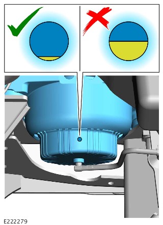 |
1
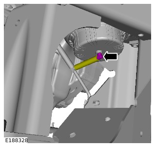
Inspect the left and right active engine mount switch positions as shown in the image
|
|
|
Is the active engine mount switch clearly visible as shown in the image?
Yes
The active engine mount may still be serviceable even if the switch is clearly visible. GO toD4. and perform a vacuum test of the engine mount. Only install a new engine mount if the vacuum test fails
No
|

For a complete list of all Diagnostic Trouble Codes (Diagnostic trouble code(s)) that could be set on this vehicle, please refer to Section 100-00. REFER to:Diagnostic Trouble Code Index - TDV6 3.0L Diesel /TDV6 3.0L Diesel - Gen 1.5/TDV6 3.0L Diesel - Gen 2, DTC: Powertrain Control Module B10A2-07 to P02D7-32 (100-00 General Information, Description and Operation).
CYLINDER PRESSURES CHECK USING DIAGNOSTIC EQUIPMENT (G2369884)
SPECIAL TOOL(S)

JLR-CF54
Jaguar Land Rover (JLR) approved diagnostic equipment
BSU2
JLR approved battery support unit
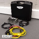
JLR-IDU2
IDU 2 Kit
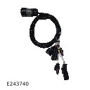
IDU06
Petrol Compression Test Cable
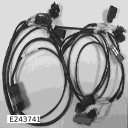
IDU06C
Diesel Compression Test Cable
The Jaguar Land Rover (JLR) approved diagnostic equipment will read the Vehicle Identification Number (VIN) for the vehicle.
- Connect the Jaguar Land Rover (JLR) approved battery support unit.
- Connect the JLR approved diagnostic equipment to the vehicle and begin a new session.
- Follow the JLR approved diagnostic equipment prompts.
- Select the 'Diagnosis' Session Type.
- Select any of the following symptoms:
- Powertrain-Engine System-Engine Performance
- Powertrain-Engine System-Starting System
- Electrical-Instruments-Warning Lamps-Engine Malfunction Lamp
- Run Inline diagnostic unit 2, relative compression test - XXXX
- When all of the tasks are complete, exit the session.
- Disconnect the JLR approved diagnostic equipment and the JLR approved battery support unit.
-
CYLINDER HEAD DISTORTION (G1676086)
GENERAL PROCEDURES- 01.01.34
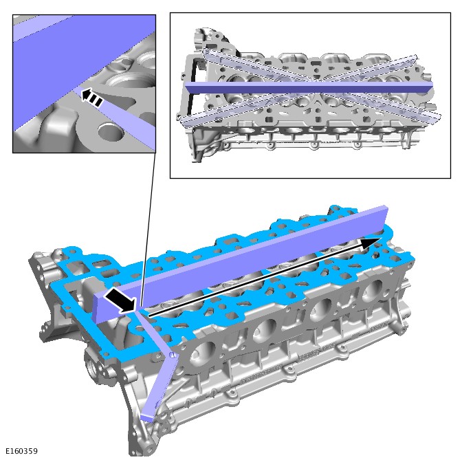
- CYLINDER HEAD - DISTORTION MEASUREMENT
- ALL DERIVATIVES
- 0.10
- USED WITHINS
CHECK-
CAUTION:
Machine the minimum thickness of material from the cylinder head to meet specification. If a selection of cylinder head gaskets are available, increase the thickness of the cylinder head gasket by one size.
If the cylinder head exceeds the maximum value, the cylinder head must be machined.NOTES:-
Prior to having the cylinder head machined, prior approval is required by Jaguar or Land Rover engineering.
-
If the cylinder head requires machining, this must be carried out by a local engineering company.
Refer to:Specifications (303-01A Engine - TDV6 3.0L Diesel /TDV6 3.0L Diesel - Gen 1.5/TDV6 3.0L Diesel - Gen 2, Specifications).Refer to:Specifications (303-01B Engine - V6 S/C 3.0L Petrol, Specifications).Refer to:Specifications (303-01C Engine - V8 S/C 5.0L Petrol, Specifications).Refer to:Specifications (303-01C Engine - V8 S/C 5.0L Petrol, Specifications). -
CYLINDER HEAD GASKET SELECTION - TDV6 3.0L DIESEL (G1453873)
SPECIAL TOOL(S)
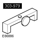
303-979
Measuring Bridge, Piston Protusion
Some variation in the illustrations may occur, but the essential information is always correct.
-
CAUTION:
Make sure that the surface is clean and free of foreign material.
Zero the gauge on the cylinder block machined face.Special Tool(s): 303-979
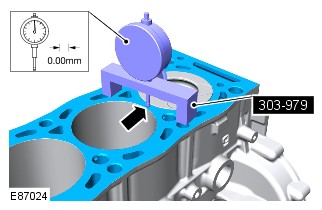
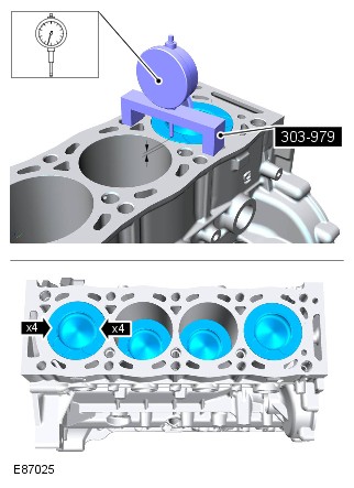
- Use the average piston protrusion measurement (taken from all piston measurements), to select the correct thickness cylinder head gasket.
Refer to:Specifications (303-01A Engine - TDV6 3.0L Diesel /TDV6 3.0L Diesel - Gen 1.5/TDV6 3.0L Diesel - Gen 2, Specifications).
CYLINDER COMPRESSION TEST - TDV6 3.0L DIESEL (G1716424)
- 12.25.01
- CYLINDER PRESSURES - CHECK
- 3000 CC, TDV6
- 1.60
- USED WITHINS
GENERAL EQUIPMENT
| EQUIPMENT NAME |
|---|
| Compression tester (petrol/diesel) |
Before disconnecting any components, make sure the area is clean and free from foreign material. When disconnected all openings must be sealed.
-
Removal steps in this procedure may contain installation details.
-
Some variation in the illustrations may occur, but the essential information is always correct.
-
The vehicle battery must be in good condition and fully charged before carrying out this procedure.
-
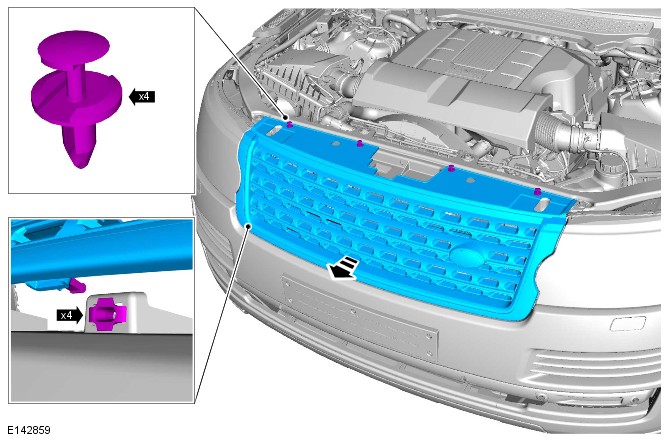
Refer to:Cowl Panel Grille (501-02 Front End Body Panels, Removal and Installation).
-
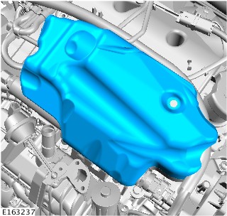
Refer to:Engine Cover - TDV6 3.0L Diesel /TDV6 3.0L Diesel - Gen 1.5/TDV6 3.0L Diesel - Gen 2 (501-05 Interior Trim and Ornamentation, Removal and Installation).
-
Refer to:Intake Air Shutoff Throttle (303-04A Fuel Charging and Controls - TDV6 3.0L Diesel /TDV6 3.0L Diesel - Gen 1.5/TDV6 3.0L Diesel - Gen 2, Removal and Installation).
-
Refer to:Oil Filter Element (303-01A Engine - TDV6 3.0L Diesel /TDV6 3.0L Diesel - Gen 1.5/TDV6 3.0L Diesel - Gen 2, Removal and Installation).
-
Refer to:Crankcase Vent Oil Separator (303-08A Engine Emission Control - TDV6 3.0L Diesel /TDV6 3.0L Diesel - Gen 1.5/TDV6 3.0L Diesel - Gen 2, Removal and Installation).


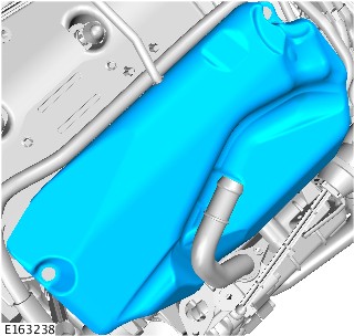


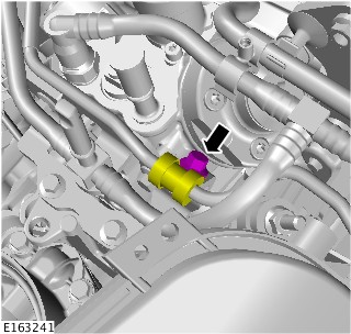
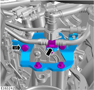


-
Crank the engine for approximately five seconds to remove any remaining fuel in the cylinders.CAUTION:
Make sure the fuel injection system is disabled before carrying out a cylinder compression test. Failure to follow this step may result in damage to the vehicle.
-
CAUTION:
Make sure the correct adaptors are used.
Install the compression tester (K00825).General Equipment: Compression tester (petrol/diesel)Torque: 10Nm

-
NOTES:
-
This step requires the aid of another technician.
-
Print graphic number E163867 in Step 22. Use this graphic to record each cylinder compression figure.
-
The vehicle battery must be in good condition and fully charged before carrying out this procedure.
Crank the engine for 10 seconds and record the figure displayed on the compression test gauge. Make sure the pressure is released from the compression test gauge after each cylinder recording. Repeat the process for all cylinders. -


- To install, reverse the removal procedure.
- The minimum cylinder compression reading recorded must be within 10% of the maximum cylinder compression reading recorded. If the difference across the cylinders is higher than 10% please contact dealer technical support (DTS) for further assistance.
- Using the Land Rover approved diagnostic equipment, read and clear any diagnostic trouble codes (DTCs).
303-01A: Engine - TDV6 3.0L Diesel /TDV6 3.0L Diesel - Gen 1.5/TDV6 3.0L Diesel - Gen 2
ENGINE - TDV6 3.0L DIESEL /TDV6 3.0L DIESEL - GEN 1.5/TDV6 3.0L DIESEL - GEN 2 (G1950015)
EXTERNAL VIEWS
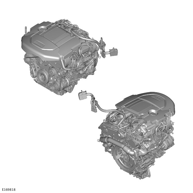
The TDV6 3.0L Diesel engine is a V6 configuration unit with two banks of three cylinders arranged at 60 degrees to each other. There are four valves per cylinder, which are operated by two overhead camshafts per cylinder bank.
The cylinder block is coupled with a cast oil pan to provide a lightweight, compact and very stiff bottom end. The cylinder heads are fitted with integrated intake manifold and camshaft covers. The exhaust manifolds are unique for each cylinder head. An acoustic cover is fitted over the upper engine to absorb engine-generated noise.
Depending on the market, there are two variants of the TDV6 3.0L Diesel engine:
- Single turbocharger variant
- Twin turbocharger variant.
The single turbocharger variant uses a Variable Geometry Turbocharger (VGT), the twin turbocharger variant uses two turbochargers. The twin turbocharger variant comprises a VGT as a primary turbocharger, and a fixed vane type as a secondary turbocharger.
A low compression ratio of 16:1 contributes to improved emissions quality, quieter combustion and compatibility with the engine’s unique forced induction system. For additional information, refer to:Intake Air Distribution and Filtering (303-12A Intake Air Distribution and Filtering - TDV6 3.0L Diesel /TDV6 3.0L Diesel - Gen 1.5/TDV6 3.0L Diesel - Gen 2, Description and Operation).
The low compression ratio also means less heat build-up in the piston bowl and more efficient fuel burn, resulting in the production of lower levels of pollutants. It also assists with cold starting allowing a faster cranking speed.
ENGINE STRUCTURE
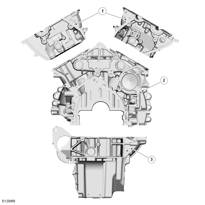
| ITEM | DESCRIPTION |
|---|---|
| 1 | Cylinder heads |
| 2 | Cylinder block |
| 3 | Oil pan |
CYLINDER BLOCK COMPONENTS
The cylinder block is a single cast construction with a hollow beam structure. This type of construction provides outstanding strength and durability and reduces engine weight and length.
Lubrication oil is distributed through the cylinder block, via a main oil gallery and channels bored in the block, to all critical moving parts. These channels divert oil to the main and connecting rod bearings via holes machined into the crankshaft.
A tapping at the rear of the cylinder block connects a pipe to the turbochargers by means of banjo connections. Oil is supplied, under pressure via this tapping, from the oil pump to provide lubrication for the bearings of the turbochargers.
Cylinder cooling is achieved by coolant circulating through chambers in the cylinder block casting.
Two hollow dowels are used to locate the cylinder heads to the cylinder block, one on each side at the rear of the unit.
A port is included at the right and left side of the cylinder block, below each of the turbochargers, to connect the turbochargers oil return pipe to the oil pan.
Two coolant drain plugs are installed in the cylinder block. One is fitted in the rear right side, and the other is fitted in the middle of the cylinder block on the left side.
PISTON COOLING JETS
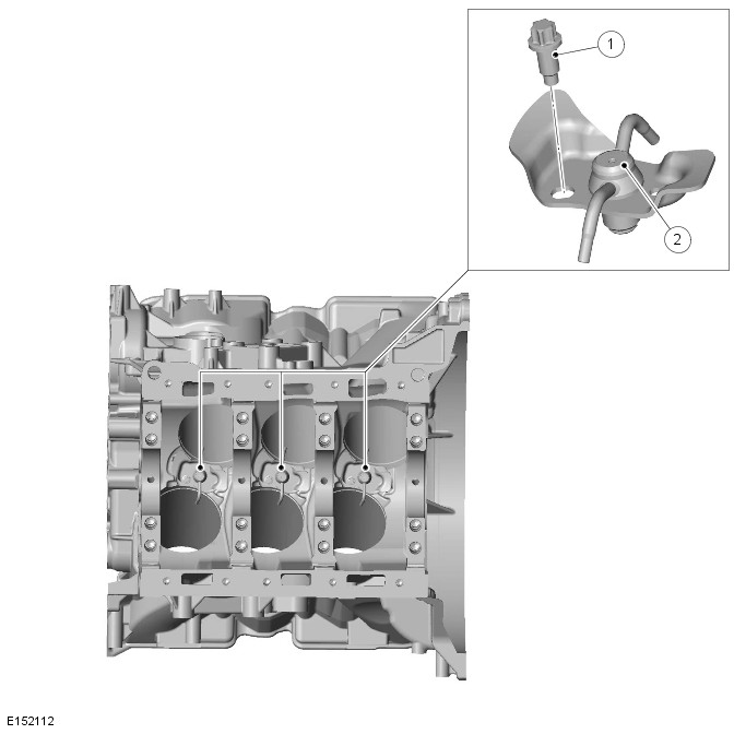
| ITEM | DESCRIPTION |
|---|---|
| 1 | Bolt |
| 2 | Cooling jet |
Jets located in the cylinder block provide piston and gudgeon pin lubrication and cooling. These jets spray oil on to the inside of the piston, the oil then flows through 2 internal wave shaped channels to help cool each piston crown.
CYLINDER NUMBERING
Front of engine is at cylinder 1
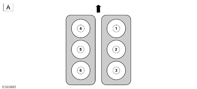
| ITEM | DESCRIPTION |
|---|---|
| A | Engine rear |
DIN standard cylinder firing order: 1,4,2,5,3,6
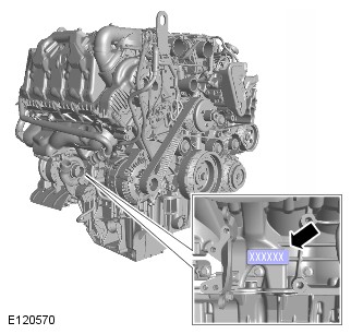
Engine serial number is stamped on the right side of the cylinder block.
CRANKSHAFT
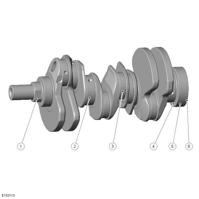
| ITEM | DESCRIPTION |
|---|---|
| 1 | Oil pump drive |
| 2 | Main bearing journal |
| 3 | Connecting rod bearing journal |
| 4 | Rear drive flange |
| 5 | Rear oil seal location |
| 6 | Reluctor ring location |
The crankshaft runs in four bearings with clamped two layer bearing shells. The upper and lower shells of bearing number 4 are flanged, which limits the end float of the crankshaft. The main bearing caps are double bolted and cross bolted to increase the strength and rigidity of the engine block.
The main bearings are selective split plain bearings. An oil groove in the top half of each bearing transfers oil into the crankshaft for lubrication of the connecting rod bearings.
Crankshaft Rear Oil Seal
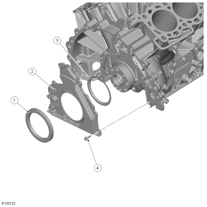
| ITEM | DESCRIPTION |
|---|---|
| 1 | Crankshaft reluctor ring |
| 2 | Crankshaft rear seal retainer |
| 3 | Crankshaft rear seal |
| 4 | Bolt (10 of) |
The crankshaft rear seal and retainer assembly is a one-piece unit and is supplied with its own fitting sleeve. The seal and retainer have two locating dowels, ten fixing bolts and a seal. In addition, the retainer has a location for the Crankshaft Position Sensor (CKP). For additional information, refer to:Electronic Engine Controls (303-14A Electronic Engine Controls - TDV6 3.0L Diesel /TDV6 3.0L Diesel - Gen 1.5/TDV6 3.0L Diesel - Gen 2, Description and Operation).
Crankshaft Reluctor Ring
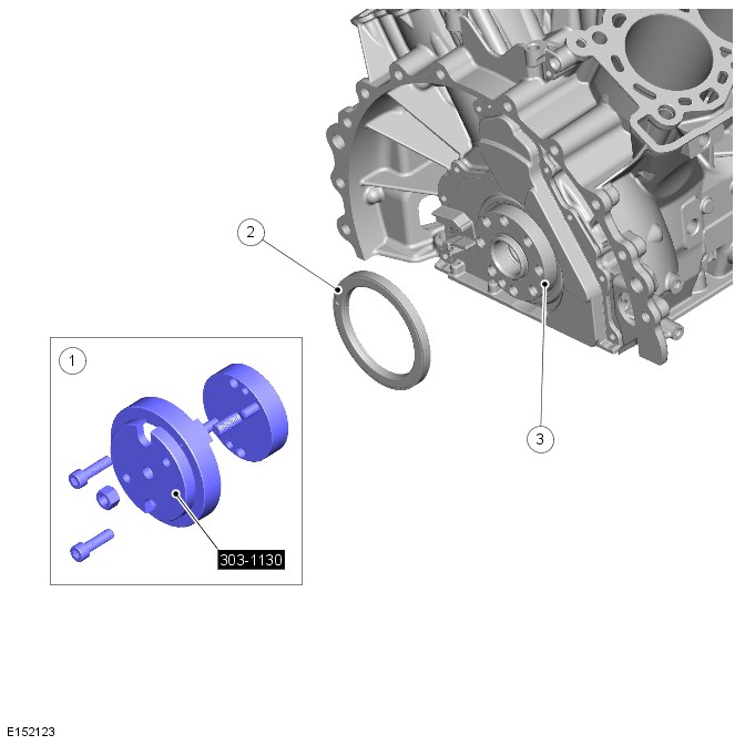
| ITEM | DESCRIPTION |
|---|---|
| 1 | Special tool |
| 2 | Reluctor ring |
| 3 | Crankshaft |
The crankshaft reluctor ring is located on the rear of the crankshaft. It is pressed onto the crankshaft using a special tool, which also precisely aligns the reluctor ring for crankshaft position and timing.
The crankshaft reluctor ring consists of 60 magnets minus 2 for Powertrain Control Module (PCM) crankshaft position reference and synchronization. The magnets cannot be seen on the reluctor ring, which therefore can only be positioned using the special tool.
If the reluctor ring is removed for any reason, then a new reluctor ring must be fitted.
Crankshaft Pulley/Mass Damper
The crankshaft pulley/mass damper is bolted to the front of the crankshaft to provide the drive for the engine accessory components. For additional information, refer to:Accessory Drive (303-05A Accessory Drive - TDV6 3.0L Diesel /TDV6 3.0L Diesel - Gen 1.5/TDV6 3.0L Diesel - Gen 2, Description and Operation).
OIL PAN COMPONENTS
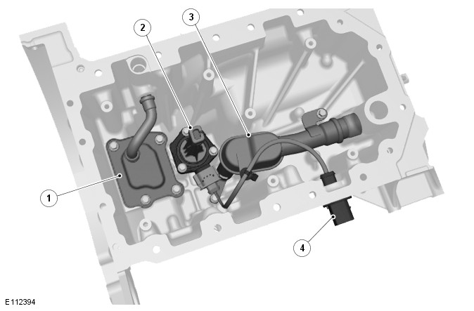
| ITEM | DESCRIPTION |
|---|---|
| 1 | Oil scavenge reservoir |
| 2 | Oil level and temperature sensor |
| 3 | Oil pick-up pipe |
| 4 | Oil level and temperature sensor connector |
The structural oil pan is fitted to the lower cylinder block to stiffen the base structure of the engine, helping to reduce Noise,Vibration and Harshness (NVH). The oil pan also incorporates an oil baffle plate to reduce oil foaming and splash.
The oil pan is secured to the cylinder block with two dowels, two locator pins for the gasket and 18 retaining bolts.
Three different lengths of bolts are used:
- M8 x 20 (9 of).
- M8 x 75 (1 of).
- M6 x 105 (8 of).
A gasket seals the joint between the oil pan and the cylinder block.
An oil pick-up pipe with integral strainer locates in the oil pan to provide oil to the crankshaft driven oil pump.
An oil level and temperature sensor provides an electronic indication of the oil level. This removes the requirement for the mechanical dipstick. An advantage in comparison with the static 'dipstick' method is that all marginal influences, for example vehicle being on a slope, lateral and longitudinal acceleration, are compensated for by averaging.
The values determined can be used to signal that the minimum oil level has been reached or to display the current oil level if required.
The sensor is mounted inside the oil pan where it sends an ultrasonic pulse vertically upward, it then measures the time for the pulse to be reflected back from the top surface of the oil.
PISTON AND CONNECTING ROD ASSEMBLY
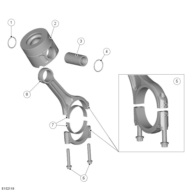
| ITEM | DESCRIPTION |
|---|---|
| 1 | Circlip |
| 2 | Piston |
| 3 | Gudgeon pin |
| 4 | Circlip |
| 5 | Connecting rod identification |
| 6 | Connecting rod bolts (2 of) |
| 7 | Connecting rod bearings (2 of) |
| 8 | Connecting rod |
The connecting rods have fracture-split bearing caps. The bearing caps are produced by fracturing the opposing sides of the connecting rod at the bearing horizontal center-line. As well as being easier to manufacture, when reassembled the fractured surfaces interlock to form a strong seamless joint. The cylinder position is etched on adjoining sides of the joint to identify matching connecting rods and bearing caps. The connecting rod bearings are selective split plain bearings. The connecting rod bearing is 'bismuth coated tri-metal', which is a manufacturing process that layers the bearing material to produce a higher load capacity for improved durability.
The connecting rods are not selective.
Piston And Connecting Rod Orientation
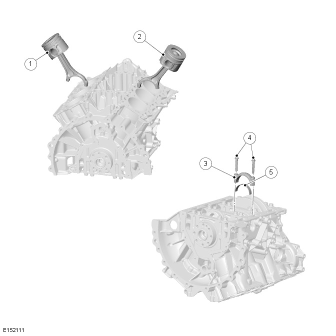
| ITEM | DESCRIPTION |
|---|---|
| 1 | Piston and connecting rod assembly, cylinders 4-6 |
| 2 | Piston and connecting rod assembly, cylinders 1-3 |
| 3 | Connecting rod bearing cap (6 of) |
| 4 | Bolts (12 of) |
| 5 | Connecting rod lower bearing (6 of) |
When installing a connecting rod, ensure the back of the connecting rod faces the center of the 'vee'.
The pistons are fitted with three rings. The piston crown incorporates a pronounced bowl. This forms the combustion chamber, which promotes swirl and turbulence necessary for good combustion and improved emissions. In addition, the piston skirt has a molybdenum-coated surface, which counteracts scoring of the cylinder bore and piston.
The piston also incorporates a double wave gallery within the piston crown to enhance piston cooling. The pistons are supplied oil by means of spray jets located in the cylinder block oil gallery. These jets ensure optimum piston cooling to counteract the high temperatures generated by the combustion process.
Each piston is installed on a gudgeon pin located in a bushing in the connecting rod.
PISTON RINGS ORIENTATION
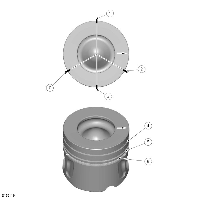
| ITEM | DESCRIPTION |
|---|---|
| 1 | Ring gap - Oil control ring |
| 2 | Ring gap - Upper compression ring |
| 3 | Spiral joint - Oil control ring |
| 4 | Upper compression ring |
| 5 | Lower compression ring |
| 6 | Oil control ring |
| 7 | Ring gap - Lower compression ring |
When installing pistons ensure the arrows on the piston crowns all point to the front of the engine. All pistons are common single grade/single part number for all engines.
The piston top ring is a taper type and is fitted with the taper to the top of the piston. All rings marked 'top' are assembled with 'top' uppermost. All rings must be spaced evenly around the piston before installing. The circumference gap of the double beveled oil control ring must be opposite the spiral control joint.
CAMSHAFT TIMING COMPONENTS - PRIMARY DRIVE
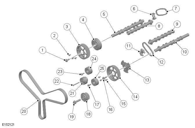
| ITEM | DESCRIPTION |
|---|---|
| 1 | Bolt |
| 2 | Bolt (3 off) |
| 3 | Right camshaft timing pulley |
| 4 | Camshaft hub |
| 5 | Exhaust camshaft - Bank 1 |
| 6 | Secondary timing chain tensioner - Bank 1 |
| 7 | Secondary timing chain - Bank 1 |
| 8 | Intake camshaft - Bank 1 |
| 9 | Intake camshaft - Bank 2 |
| 10 | Exhaust camshaft - Bank 2 |
| 11 | Secondary timing chain tensioner - Bank 2 |
| 12 | Secondary timing chain - Bank 2 |
| 13 | Camshaft hub |
| 14 | Left camshaft timing pulley |
| 15 | Bolt (3 of) |
| 16 | Bolt |
| 17 | Bolt |
| 18 | Crankshaft drive gear |
| 19 | Bolt |
| 20 | Timing belt |
| 21 | Timing belt tensioner |
| 22 | Bolt |
| 23 | Bolt |
| 24 | Idler pulley |
| 25 | Idler pulley |
Primary drive is provided by a toothed timing belt from the crankshaft to the exhaust camshaft gears of each cylinder bank via two idler pulleys and a tensioner.
Timing belt adjustment is carried out by the eccentric type tensioner mounted on the right front face of the cylinder block.
The primary drive cover is secured to the front of the cylinder block, cylinder heads, intake manifolds and oil pump housing. The cover is sealed with a gasket. A bridge piece closes the back of the cover in between the cylinder heads.
CAMSHAFT TIMING COMPONENTS - SECONDARY DRIVE
Bank 1 cylinder head installation shown, Bank 2 is similar.
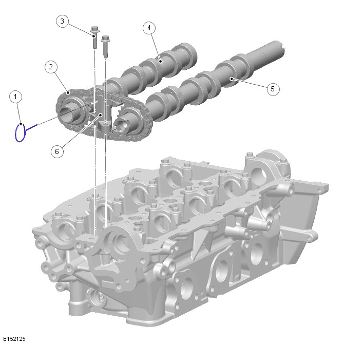
| ITEM | DESCRIPTION |
|---|---|
| 1 | Tensioner firing pin |
| 2 | Secondary timing chain |
| 3 | Bolt (2 of) |
| 4 | Intake camshaft |
| 5 | Exhaust camshaft |
| 6 | Timing chain tensioner |
Secondary drive is provided by two short secondary timing chains, which transfer drive from the exhaust camshaft sprockets to the intake camshaft sprockets. The secondary drives are located at the rear of the Bank 1 cylinder head and the front of the Bank 2 cylinder head. This allows for a much shorter and simpler run for the timing belt at the front of the engine.
Each secondary timing chain is tensioned via an automatic chain tensioner, which acts directly on the chains via a guide rail. The tensioners are located between the exhaust and intake camshafts at the front or rear of the cylinder head, depending on the cylinder bank.
The tensioner firing pin holds the automatic chain tensioner in a compressed state to aid installation.
CYLINDER HEAD COMPONENTS
Bank 2 cylinder head shown, Bank 1 cylinder head is similar.
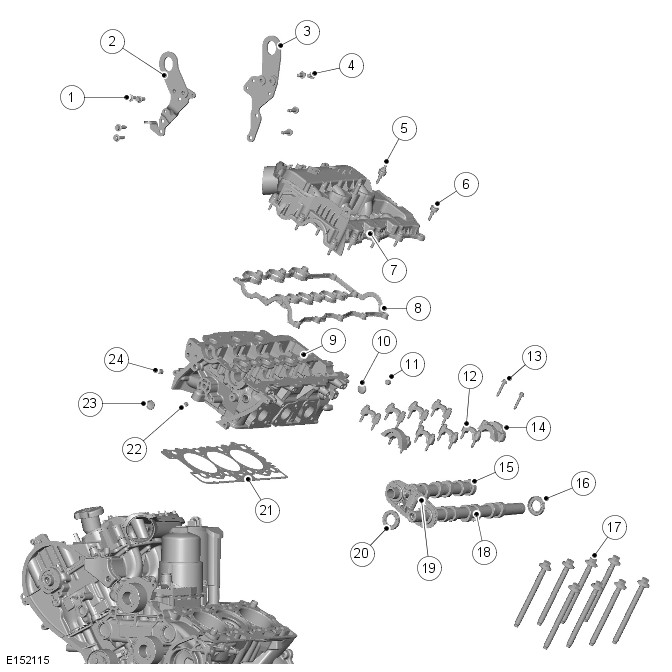
| ITEM | DESCRIPTION |
|---|---|
| 1 | Bolt (4 of) |
| 2 | Front lifting eye |
| 3 | Rear lifting eye |
| 4 | Bolt (4 of) |
| 5 | Camshaft cover stud (6 of) |
| 6 | Camshaft cover bolt (7 of) |
| 7 | Intake manifold camshaft cover assembly |
| 8 | Gasket |
| 9 | Cylinder head |
| 10 | Plug (coolant) |
| 11 | Plug (oil port) |
| 12 | Camshaft bearing cap (7 of) |
| 13 | Bolts (18 of) |
| 14 | Camshaft bearing cap and seal housing (2 of) |
| 15 | Intake camshaft |
| 16 | Seal |
| 17 | Cylinder head bolts (8 of) |
| 18 | Exhaust camshaft |
| 19 | Secondary timing chain |
| 20 | Seal |
| 21 | Cylinder head gasket |
| 22 | Plug (oil port) |
| 23 | Plug (coolant) |
| 24 | Plug (oil port) |
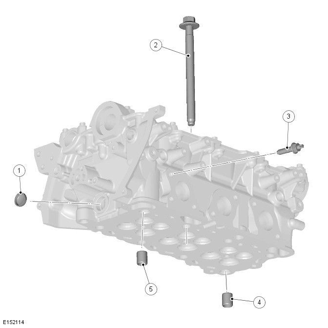
| ITEM | DESCRIPTION |
|---|---|
| 1 | Blanking plug - coolant (2 of) |
| 2 | Cylinder head bolt (8 of) |
| 3 | Exhaust manifold stud (6 of) |
| 4 | Cylinder head dowel |
| 5 | Cylinder head dowel |
The cylinder heads are unique to each cylinder bank. Eight deep-seated bolts help reduce distortion and secure each cylinder head to the cylinder block. The cylinder head bolts are located beneath the camshafts, four under the intake camshaft and four under the exhaust camshaft. Two hollow dowels align each cylinder head with the cylinder block.
The cylinder heads cannot be reworked.
The cylinder head gasket is available in five different thicknesses. The choice of gasket thickness is dependent on the maximum piston protrusion. Gasket thickness is identified by serrations cut into the front end of the gasket. For additional information, refer to:Engine (303-01A Engine - TDV6 3.0L Diesel /TDV6 3.0L Diesel - Gen 1.5/TDV6 3.0L Diesel - Gen 2, Description and Operation).
The cylinder head has four ports machined at each cylinder location, two exhaust ports and two intake ports. One of the intake ports is helical and functions as a swirl port, the other is arranged laterally as a tangential port and functions as a charge port.
The camshafts are of a hollow tube construction, with pressed on lobes. Each camshaft is retained by caps, five for the exhaust camshafts and four for the intake camshafts. Location letters, A to I for the intake camshaft and R to Z for the exhaust camshaft, are marked on the outer faces of the caps for each cylinder head.
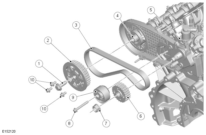
| ITEM | DESCRIPTION |
|---|---|
| 1 | Bolt |
| 2 | Camshaft gear |
| 3 | Toothed belt |
| 4 | Left cylinder head exhaust camshaft |
| 5 | High Pressure (HP) fuel pump |
| 6 | High Pressure (HP) fuel pump gear |
| 7 | Nut |
| 8 | Bolt |
| 9 | Tensioner |
| 10 | Bolts |
The left cylinder bank exhaust camshaft is machined to accept a rear camshaft gear. The rear camshaft gear provides drive for the High Pressure (HP) fuel pump.
The HP fuel pump drive incorporates the following main components:
- Camshaft gear
- HP fuel pump gear
- Toothed belt
- Tensioner.
For additional information, refer to:Fuel Charging and Controls (303-04A Fuel Charging and Controls - TDV6 3.0L Diesel /TDV6 3.0L Diesel - Gen 1.5/TDV6 3.0L Diesel - Gen 2, Description and Operation).
The exhaust camshaft gear of the Bank 2 cylinder head also incorporates a reluctor ring, which is used in conjunction with the Camshaft Position Sensor (CMP) to measure engine position. For additional information, refer to:Electronic Engine Controls (303-14A Electronic Engine Controls - TDV6 3.0L Diesel /TDV6 3.0L Diesel - Gen 1.5/TDV6 3.0L Diesel - Gen 2, Description and Operation).
The Bank 1 cylinder head exhaust camshaft is machined at the rear end to provide a drive connection for the vacuum and oil scavenge pump.
The fuel injection nozzles are centrally mounted above each cylinder. For additional information, refer to:Fuel Charging and Controls (303-04A Fuel Charging and Controls - TDV6 3.0L Diesel /TDV6 3.0L Diesel - Gen 1.5/TDV6 3.0L Diesel - Gen 2, Description and Operation).
The glow plugs are arranged centrally on the intake side of the cylinder heads, between the two intake ports of each cylinder. For additional information, refer to:Glow Plug System (303-07C Glow Plug System - TDV6 3.0L Diesel /TDV6 3.0L Diesel - Gen 1.5/TDV6 3.0L Diesel - Gen 2, Description and Operation).
The engine lifting eyes are bolted to the cylinder head, one at the front and two at the rear of the engine, one per cylinder head.
Bank 1 installation shown, Bank 2 is similar.
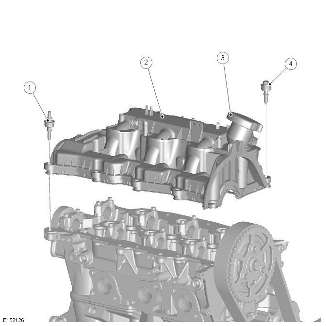
| ITEM | DESCRIPTION |
|---|---|
| 1 | Camshaft cover stud (8 of) |
| 2 | Camshaft cover - intake manifold assembly |
| 3 | Oil filler cap |
| 4 | Camshaft cover bolt (5 of) |
The Bank 1 camshaft cover incorporates an outlet for the full load engine breather and the engine oil filler cap. The Bank 2 camshaft cover incorporates an outlet for the part load engine breather. For additional information, refer to:Engine Emission Control (303-08A Engine Emission Control - TDV6 3.0L Diesel /TDV6 3.0L Diesel - Gen 1.5/TDV6 3.0L Diesel - Gen 2, Description and Operation).
In-groove gaskets seal the joints between the camshaft covers and the cylinder heads. Together with spacers and seals on the camshaft cover fasteners, the gaskets are isolate the covers from direct contact with the cylinder heads, to reduce noise.
Bank 1 installation shown, Bank 2 is similar.
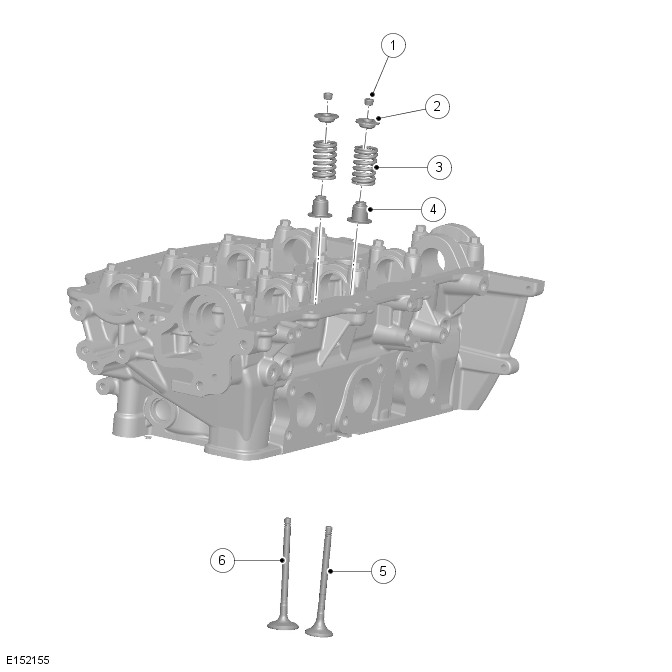
| ITEM | DESCRIPTION |
|---|---|
| 1 | Valve spring collet - 24 of (12 per cylinder head) |
| 2 | Valve spring retainer - 24 of (12 per cylinder head) |
| 3 | Valve spring - 24 of (12 per cylinder head) |
| 4 | Valve stem seal - 24 of (12 per cylinder head) |
| 5 | Exhaust valve - 12 of (6 per cylinder head) |
| 6 | Intake valve - 12 of (6 per cylinder head) |
Each cylinder head incorporates two overhead camshafts operating four valves per cylinder via rocker arms with hydraulic valve tappets.
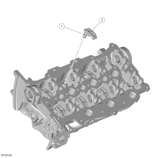
| ITEM | DESCRIPTION |
|---|---|
| 1 | Hydraulic valve tappet - 24 of (12 per cylinder head) |
| 2 | Rocker arm - 24 of (12 per cylinder head) |
The lightweight valve gear provides good economy and noise levels. Valve head diameters are 31 mm (1.220 in) for the exhaust and 35 mm (1.378 in) for the intake. All valves have 5 mm (0.197 in) diameter stems supported in seats and guide inserts. Valve spring collets, collars seats locate single valve springs on both intake and exhaust valves. Valve stem seals are integrated into the valve spring seats.
VACUUM AND OIL SCAVENGE PUMP
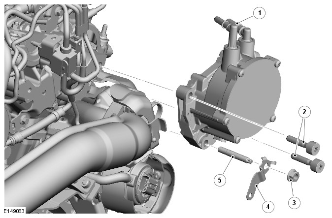
| ITEM | DESCRIPTION |
|---|---|
| 1 | Vacuum pipe connections |
| 2 | Torx bolt (2 of) |
| 3 | Nut |
| 4 | Bracket (emission hose) |
| 5 | Stud |
The vacuum and oil scavenge pump is located at the rear of the Bank 1 cylinder head and driven from the exhaust camshaft. The pump provides the vacuum used by the Exhaust Gas Recirculation (EGR), turbocharger and brake booster systems, and scavenges oil from the turbochargers.
EXHAUST MANIFOLDS
Left exhaust manifold is shown, right exhaust manifold is similar.
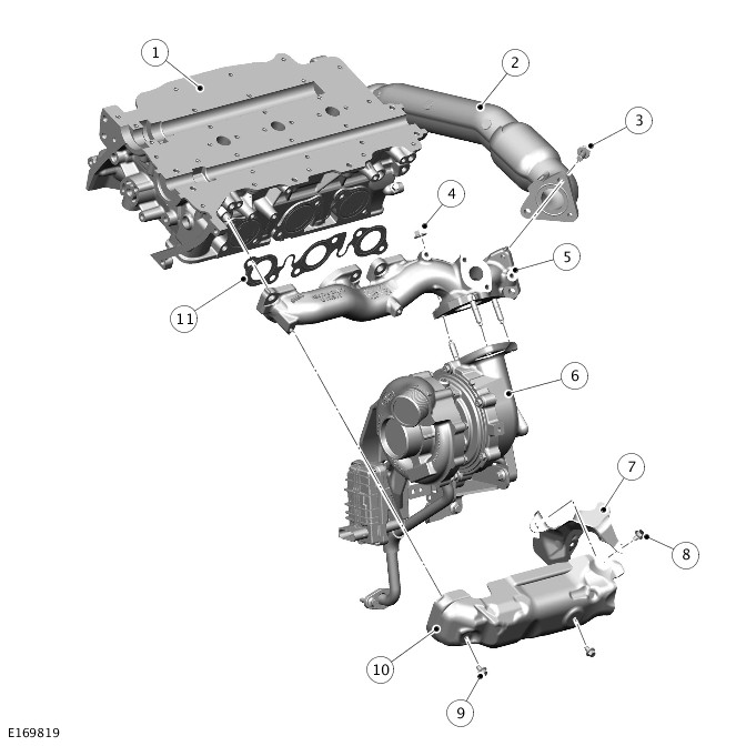
| ITEM | DESCRIPTION |
|---|---|
| 1 | Cylinder head |
| 2 | Connecting pipe |
| 3 | Bolt (3 of) |
| 4 | Nut (3 of) |
| 5 | Exhaust manifold |
| 6 | Turbocharger (primary turbocharger shown) |
| 7 | Manifold rear heat shield |
| 8 | Bolt |
| 9 | Bolt (2 of) |
| 10 | Manifold heat shield |
| 11 | Gasket |
The exhaust manifolds are cast from an iron alloy with a high nickel content giving excellent heat and corrosion resistance properties. They are sealed to the cylinder head by means of a steel gasket. Sacrificial plastic sleeves are used to align the manifolds. These sleeves must be changed when refitting the manifolds. Spacers on the securing bolts allow the manifolds to expand and retract with changes of temperature while maintaining the clamping loads.
The Bank 1 exhaust manifold has a connection for the High Pressure (HP) Exhaust Gas Recirculation (EGR) valve.
On single turbocharger variant vehicles the Variable Geometry Turbocharger (VGT) is attached to the left exhaust manifold and secured to three studs on a flange on the manifold with nuts. On production, no gasket is used to seal the joint surface between the VGT and the manifold. In-service vehicles will require a service gasket to be fitted if the joint surface is disturbed.
On twin turbocharger variant vehicles the secondary turbocharger is attached to the right exhaust manifold and secured to three studs on a flange on the manifold with nuts. On production, no gasket is used to seal the joint surface between the secondary turbocharger and the manifold. In-service vehicles will require a service gasket to be fitted if the joint surface is disturbed.
LUBRICATION SYSTEM
Twin turbocharger variant shown, single turbocharger variant is similar.
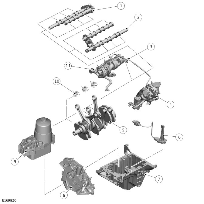
| ITEM | DESCRIPTION |
|---|---|
| 1 | Intake camshaft |
| 2 | Exhaust camshaft |
| 3 | Turbocharger oil supply |
| 4 | Primary turbocharger |
| 5 | Crankshaft and connecting rods |
| 6 | Oil level and temperature sensor |
| 7 | Oil pan |
| 8 | Oil pump |
| 9 | Oil cooler and filter assembly |
| 10 | Piston cooling jets |
| 11 | Secondary turbocharger |
Oil is drawn from the oil pan and pressurized by the oil pump. The output from the oil pump is then filtered and distributed through internal oil passageways.
All moving parts are lubricated by pressure or splash oil. Pressurized oil is also provided for operation of the hydraulic valve tappets and the timing gear chain tensioners.
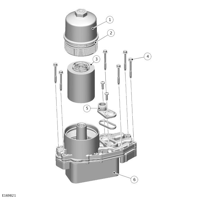
| ITEM | DESCRIPTION |
|---|---|
| 1 | Filter housing |
| 2 | O-ring seal |
| 3 | Filter element |
| 4 | Retaining bolt (6 of) |
| 5 | Coolant outlet connection |
| 6 | Oil cooler assembly |
The engine is lubricated by a force-feed oil circulation system with a full flow oil filter. The oil cooler forms a unit with the oil filter, which is mounted centrally in the middle of the cylinder block between the two banks of cylinders. The engine oil is cooled using the engine cooling system. For additional information, refer to:Engine Cooling (303-03A Engine Cooling - TDV6 3.0L Diesel /TDV6 3.0L Diesel - Gen 1.5/TDV6 3.0L Diesel - Gen 2, Description and Operation).
Oil returns to the oil pan under gravity. Large drain holes through the cylinder heads and cylinder block ensure the quick return of the oil, reducing the volume of oil required and enabling an accurate check of the contents soon after the engine stops.
System replenishment is through the oil filler cap on the right camshaft cover.
The oil pick-up is immersed in the oil reservoir to provide a supply to the oil pump during all normal vehicle attitudes. A mesh screen in the intake prevents debris from entering the oil system.
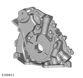
The oil pump is a G-rotor two stage pressure pump with solenoid control to switch between low and high pressure modes depending on engine speed and load to optimize fuel economy.
It is bolted to the front of the cylinder block. It is sealed by means of a gasket, which is recessed into the oil pump housing. The pump intake and outlet ports align with oil passages in the cylinder block.
The pumping element is an eccentric rotor, which is directly driven by flats on the crankshaft. An integral pressure relief valve regulates pump outlet pressure at 4.5 bar (65.25 lb/in²).
The front crankshaft oil seal is housed in the oil pump casing and is fitted such that its front face is 1 mm (0.04 in) under flush with the machined front face of the oil pump.
The seal is not to be pushed all the way into the bore as this will block the seal drains.
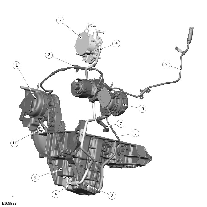
| ITEM | DESCRIPTION |
|---|---|
| 1 | Primary turbocharger |
| 2 | Turbocharger oil feed pipes |
| 3 | Vacuum and oil scavenge pump |
| 4 | Oil scavenge pipe |
| 5 | Oil extraction tube |
| 6 | Secondary turbocharger - If equipped |
| 7 | Secondary turbocharger oil return tube - If equipped |
| 8 | Drain plug |
| 9 | Secondary reservoir |
| 10 | Primary turbocharger oil return tube |
Due to the wide range of inclines Land Rover vehicles operate across, the geometry of the oil pan has been configured to guarantee oil pick-up across all operating angles. An oil scavenge system has been developed to guarantee excellent oil flow through the turbochargers on severe side-slopes. At extreme angles there is a risk the turbochargers may be below the oil level in the oil pan, restricting oil return flow.
To overcome this, the engine uses:
- The oil pump to supply oil to the turbocharger bearings from the main reservoir of the oil pan.
- A secondary reservoir in the oil pan, sealed off from the main reservoir, to receive oil from the turbocharger bearings.
- The vacuum and oil scavenge pump to assist the oil flow from the turbocharger bearings by scavenging oil from the secondary reservoir into the right camshaft cover.
For service, a drain plug and an oil extraction tube are installed to drain the main body of the oil pan.
OIL LEVEL CHECK
The engine oil level can be displayed in the message center on the Instrument Cluster (IC).
For accuracy, oil level checks should be performed with the vehicle on level ground when the oil is hot. The vehicle needs to stand for approximately 10 minutes, after the engine is switched off, to allow the oil to drain back into the sump and the oil level to stabilize. The oil level system will not give a reading until the oil level has stabilized.
The method of checking the oil level can be found in the oil draining and filling procedures.
For additional information, refer to:(303-01A Engine - TDV6 3.0L Diesel /TDV6 3.0L Diesel - Gen 1.5/TDV6 3.0L Diesel - Gen 2)
Operation of the engine is controlled by the Powertrain Contol Module (PCM).For additional information, refer to:Electronic Engine Controls (303-14A Electronic Engine Controls - TDV6 3.0L Diesel /TDV6 3.0L Diesel - Gen 1.5/TDV6 3.0L Diesel - Gen 2, Description and Operation).
ENGINE - TDV6 3.0L DIESEL /TDV6 3.0L DIESEL - GEN 1.5/TDV6 3.0L DIESEL - GEN 2 (G2094377)
Engine Data - Low Flow Fuel Injection System
| ENGINE DESCRIPTION | ENGINE CAPACITY | MAXIMUM ENGINE TORQUE (EEC) (SAE) | MAXIMUM ENGINE POWER (EEC) (SAE) | COMPRESSION RATIO | BORE | STROKE |
|---|---|---|---|---|---|---|
| 60° "Vee" • 6 Cylinder • 24 Valves | 2993 ccm | 600 Nm at 2000 RPM | 190 kW at 4000 RPM | 16.1:1 ± 0.5 | 84 | 90 |
Engine Data - Standard Flow Fuel Injection System
| ENGINE DESCRIPTION | ENGINE CAPACITY | MAXIMUM ENGINE TORQUE (EEC) (SAE) | MAXIMUM ENGINE POWER (EEC) (SAE) | COMPRESSION RATIO | BORE | STROKE |
|---|---|---|---|---|---|---|
| 60° "Vee" • 6 Cylinder • 24 Valves | 2993 ccm | 600 Nm at 2000 RPM | 223 kW at 4000 RPM | 16.1:1 ± 0.5 | 84 | 90 |
Engine Firing Order
| FIRING ORDER |
|---|
| 1:4:2:5:3:6 |
Glow Plug
| SPECIFICATION |
|---|
| 9X2Q-6M090-AC |
Lubricants, Fluids, Sealers and Adhesives
| DESCRIPTION | SPECIFICATION |
|---|---|
| Engine oil - Vehicles with diesel particulate filter | SAE 5W30 STJLR.03.5005 |
| Engine oil - Vehicles without diesel particulate filter | SAE 5W30 STJLR.03.5003 |
| Sealant | WSE–M4G323–A5 |
| Core plug and stub pipe retainer | WSK-M2G349-A7 |
| Cooling system fluid | Havoline Extended Life Coolant (XLC) |
Capacities
| DESCRIPTION | LITERS |
|---|---|
| Engine oil initial fill | 6.75 |
| Engine oil service fill with oil filter change | 5.9 |
Cylinder Head and Valve Train
| ITEM | SPECIFICATION |
|---|---|
| Valve guide inner diameter (mm) | 5.980 ± 0.010 |
| Intake valve effective length (mm) (tip to gauge line) | 94.99mm +/- 0.15 |
| Exhaust valve effective length (mm) (tip to gauge line) | 94.45mm +/-0.15 |
| Valve stem to guide clearance intake diametrical (mm) | 0.027 - 0.063 |
| Valve stem to guide clearance exhaust diametrical (mm) | 0.037 - 0.073 |
| Valve head diameter intake (mm) | 27.8mm +/-0.1 |
| Valve head diameter exhaust (mm) | 25.2mm +/-0.1 |
| Intake valve face angle (degrees) | 44 deg 52 min +/-7min30sec |
| Exhaust valve face angle (degrees) | 44 deg 52 min +/-7min30sec |
| Valve stem diameter intake (mm) | 5.935±0.008 |
| Valve stem diameter exhaust (mm) | 5.925±0.008 |
| Valve spring free length (mm) - inlet | 38.9mm |
| Valve spring free length (mm) - exhaust | 38.9mm |
| Valve spring installed height (mm) - inlet | 31.22mm |
| Valve spring installed height (mm) - exhaust | 31.22mm |
| Camshaft lobe max lift intake (mm) | 3.75187mm |
| Camshaft lobe max lift exhaust (mm) | 3.80999mm |
| Camshaft journal to cylinder head bearing surface clearance diametrical (mm) | 0.040-0.090 |
| Camshaft journal diameter - all positions | 26.015±0.015 |
| Bearing diameter - all positions | 25.950±0.010 |
| Camshaft journal maximum run out limit (mm) | 0.030mm |
| Camshaft journal maximum out of round (mm) - all journals | 0.010mm |
| Cylinder head maximum permitted warp (mm) flatness specification | 0.2mm (0.008 in) |
| Cylinder block maximumpermitted warp (flatness specification) | 0.2mm (0.008 in) |
Cylinder Head Gasket
| IDENTIFICATION | GASKET THICKNESS (MM) | PISTON PROTRUSION (MM) |
|---|---|---|
| 2 | 1.17 | 0.552 - 0.603 |
| 3 | 1.22 | 0.604 - 0.655 |
| 4 | 1.27 | 0.656 - 0.707 |
| 5 | 1.32 | 0.708 - 0.760 |
Torque Specification
A = refer to procedure for correct torque sequence
| DESCRIPTION | NM | LB-FT | LB-IN |
|---|---|---|---|
| Piston cooling nozzle | 10 | 7 | - |
| Engine coolant drain plug | 18 | 13 | - |
| Cylinder head retaining bolts | A | - | - |
| Oil filter housing retaining bolts | 10 | 7 | - |
| Fuel injection pump cradle retaining bolts | 23 | 17 | - |
| Fuel injection pump to cradle retaining bolts | 23 | 17 | - |
| Fuel injection pump bracket to cradle retaining bolts | 10 | 7 | - |
| Fuel injection pump to bracket retaining bolts | 10 | 7 | - |
| Oil pump retaining bolts | 10 | 7 | - |
| Crankshaft rear oil seal housing retaining bolts | 10 | 7 | - |
| Oil pan retaining bolts M6 | 10 | 7 | - |
| Oil pan retaining bolts M8 | 23 | 17 | - |
| Oil pump pick up pipe retaining bolts | 10 | 7 | - |
| Engine oil level sensor retaining nuts | 10 | 7 | - |
| Crankshaft timing belt pulley retaining bolt | A | - | - |
| Crankshaft position sensor (CKP) retaining bolt | 5 | - | 44 |
| Timing chain tensioner retaining bolts | 10 | 7 | - |
| Camshaft bearing cap retaining bolts | A | - | - |
| Timing belt idler pulley retaining bolt | 45 | 33 | - |
| Fuel injection pump belt rear cover retaining bolts | 10 | 7 | - |
| Fuel injection pump sprocket retaining nut | 50 | 37 | - |
| Coolant outlet pipe retaining bolts | 10 | 7 | - |
| Coolant pump retaining bolts | 10 | 7 | - |
| Timing belt tensioner retaining bolt | 26 | 19 | - |
| Engine lifting eye bolts | 23 | 17 | - |
| Camshaft rear end accessory drive (READ) pulley hub retaining bolt | Stage 1 - 80 Stage 2 - 80 degrees | Stage 1 - 59 Stage 2 - 80 degrees | - |
| Camshaft front timing pulley hub retaining bolt | 80 + 80° | 59 + 80 ° | - |
| Camshaft READ pulley retaining bolt | 23 | 17 | - |
| Camshaft front timing pulley retaining bolt | 23 | 17 | - |
| Fuel injection pump timing belt tensioner bolt | 23 | 17 | - |
| Camshaft position sensor (CMP) retaining bolt | 10 | 7 | - |
| Intake manifold / camshaft cover retaining bolts | 10 | 7 | - |
| Brake vacuum pump retaining bolts | 23 | 17 | - |
| Engine oil pressure (EOP) switch | 14 | 10 | - |
| Glow plug | 11 | 8 | - |
| Fuel rail retaining bolts | 23 | 17 | - |
| Fuel rail bracket retaining bolts | 23 | 17 | - |
| Fuel injector retaining bolts | A | - | - |
| High pressure fuel line union nuts | A | - | - |
| High pressure fuel line bracket retaining bolts | 9 | - | 80 |
| Turbocharger assembly to exhaust manifold retaining nuts | 24 | 18 | - |
| Exhaust manifold to cylinder head retaining nuts | A | - | - |
| Exhaust manifold heatshield retaining bolts | 11 | 8 | - |
| Turbocharger heatshield retaining bolts | 11 | 8 | - |
| Exhaust gas recirculation (EGR) valve retaining bolts M6 | 10 | 7 | - |
| Accessory drive belt idler pulley bracket retaining bolts | 83 | 61 | - |
| Timing belt covers retaining bolts | 10 | 7 | - |
| Engine mount bracket to engine retaining bolts | 115 | 85 | - |
| Engine mount bracket to engine mounting | 130 | 96 | - |
| Engine mounting to subframe bolts. | A | - | - |
| Exhaust cross over pipe retaining nuts | 24 | 18 | - |
| Engine coolant inlet pipe retaining bolts | 10 | 7 | - |
| Coolant pump pulley retaining bolts | 25 | 18 | - |
| Crankshaft pulley/vibration damper retaining bolts | 25 | 18 | - |
| Throttle body retaining threaded stud | 10 | 7 | - |
| Wiring harness retaining nuts | 10 | 7 | - |
| Vacuum hose assembly retaining bolts | 10 | 7 | - |
| Drive plate retaining bolts | A | - | - |
| Accessory drive component bracket retaining bolts | 23 | 17 | - |
| Generator retaining bolts | 47 | 35 | - |
| Accessory drive belt tensioner retaining bolt | 47 | 35 | - |
| Accessory drive belt idler pulley retaining bolt | 47 | 35 | - |
| Air conditioning compressor bracket retaining bolts | 23 | 17 | - |
| Air conditioning compressor retaining bolts | 23 | 17 | - |
Description and Operation
ENGINE - TDV6 3.0L DIESEL /TDV6 3.0L DIESEL - GEN 1.5/TDV6 3.0L DIESEL - GEN 2 (G1950015)
EXTERNAL VIEWS
The TDV6 3.0L Diesel engine is a V6 configuration unit with two banks of three cylinders arranged at 60 degrees to each other. There are four valves per cylinder, which are operated by two overhead camshafts per cylinder bank.
The cylinder block is coupled with a cast oil pan to provide a lightweight, compact and very stiff bottom end. The cylinder heads are fitted with integrated intake manifold and camshaft covers. The exhaust manifolds are unique for each cylinder head. An acoustic cover is fitted over the upper engine to absorb engine-generated noise.
Depending on the market, there are two variants of the TDV6 3.0L Diesel engine:
- Single turbocharger variant
- Twin turbocharger variant.
The single turbocharger variant uses a Variable Geometry Turbocharger (VGT), the twin turbocharger variant uses two turbochargers. The twin turbocharger variant comprises a VGT as a primary turbocharger, and a fixed vane type as a secondary turbocharger.
A low compression ratio of 16:1 contributes to improved emissions quality, quieter combustion and compatibility with the engine’s unique forced induction system. For additional information, refer to:Intake Air Distribution and Filtering (303-12A Intake Air Distribution and Filtering - TDV6 3.0L Diesel /TDV6 3.0L Diesel - Gen 1.5/TDV6 3.0L Diesel - Gen 2, Description and Operation).
The low compression ratio also means less heat build-up in the piston bowl and more efficient fuel burn, resulting in the production of lower levels of pollutants. It also assists with cold starting allowing a faster cranking speed.
ENGINE STRUCTURE
| ITEM | DESCRIPTION |
|---|---|
| 1 | Cylinder heads |
| 2 | Cylinder block |
| 3 | Oil pan |
CYLINDER BLOCK COMPONENTS
The cylinder block is a single cast construction with a hollow beam structure. This type of construction provides outstanding strength and durability and reduces engine weight and length.
Lubrication oil is distributed through the cylinder block, via a main oil gallery and channels bored in the block, to all critical moving parts. These channels divert oil to the main and connecting rod bearings via holes machined into the crankshaft.
A tapping at the rear of the cylinder block connects a pipe to the turbochargers by means of banjo connections. Oil is supplied, under pressure via this tapping, from the oil pump to provide lubrication for the bearings of the turbochargers.
Cylinder cooling is achieved by coolant circulating through chambers in the cylinder block casting.
Two hollow dowels are used to locate the cylinder heads to the cylinder block, one on each side at the rear of the unit.
A port is included at the right and left side of the cylinder block, below each of the turbochargers, to connect the turbochargers oil return pipe to the oil pan.
Two coolant drain plugs are installed in the cylinder block. One is fitted in the rear right side, and the other is fitted in the middle of the cylinder block on the left side.
PISTON COOLING JETS
| ITEM | DESCRIPTION |
|---|---|
| 1 | Bolt |
| 2 | Cooling jet |
Jets located in the cylinder block provide piston and gudgeon pin lubrication and cooling. These jets spray oil on to the inside of the piston, the oil then flows through 2 internal wave shaped channels to help cool each piston crown.
CYLINDER NUMBERING
Front of engine is at cylinder 1
| ITEM | DESCRIPTION |
|---|---|
| A | Engine rear |
DIN standard cylinder firing order: 1,4,2,5,3,6
Engine serial number is stamped on the right side of the cylinder block.
CRANKSHAFT
| ITEM | DESCRIPTION |
|---|---|
| 1 | Oil pump drive |
| 2 | Main bearing journal |
| 3 | Connecting rod bearing journal |
| 4 | Rear drive flange |
| 5 | Rear oil seal location |
| 6 | Reluctor ring location |
The crankshaft runs in four bearings with clamped two layer bearing shells. The upper and lower shells of bearing number 4 are flanged, which limits the end float of the crankshaft. The main bearing caps are double bolted and cross bolted to increase the strength and rigidity of the engine block.
The main bearings are selective split plain bearings. An oil groove in the top half of each bearing transfers oil into the crankshaft for lubrication of the connecting rod bearings.
Crankshaft Rear Oil Seal
| ITEM | DESCRIPTION |
|---|---|
| 1 | Crankshaft reluctor ring |
| 2 | Crankshaft rear seal retainer |
| 3 | Crankshaft rear seal |
| 4 | Bolt (10 of) |
The crankshaft rear seal and retainer assembly is a one-piece unit and is supplied with its own fitting sleeve. The seal and retainer have two locating dowels, ten fixing bolts and a seal. In addition, the retainer has a location for the Crankshaft Position Sensor (CKP). For additional information, refer to:Electronic Engine Controls (303-14A Electronic Engine Controls - TDV6 3.0L Diesel /TDV6 3.0L Diesel - Gen 1.5/TDV6 3.0L Diesel - Gen 2, Description and Operation).
Crankshaft Reluctor Ring
| ITEM | DESCRIPTION |
|---|---|
| 1 | Special tool |
| 2 | Reluctor ring |
| 3 | Crankshaft |
The crankshaft reluctor ring is located on the rear of the crankshaft. It is pressed onto the crankshaft using a special tool, which also precisely aligns the reluctor ring for crankshaft position and timing.
The crankshaft reluctor ring consists of 60 magnets minus 2 for Powertrain Control Module (PCM) crankshaft position reference and synchronization. The magnets cannot be seen on the reluctor ring, which therefore can only be positioned using the special tool.
If the reluctor ring is removed for any reason, then a new reluctor ring must be fitted.
Crankshaft Pulley/Mass Damper
The crankshaft pulley/mass damper is bolted to the front of the crankshaft to provide the drive for the engine accessory components. For additional information, refer to:Accessory Drive (303-05A Accessory Drive - TDV6 3.0L Diesel /TDV6 3.0L Diesel - Gen 1.5/TDV6 3.0L Diesel - Gen 2, Description and Operation).
OIL PAN COMPONENTS
| ITEM | DESCRIPTION |
|---|---|
| 1 | Oil scavenge reservoir |
| 2 | Oil level and temperature sensor |
| 3 | Oil pick-up pipe |
| 4 | Oil level and temperature sensor connector |
The structural oil pan is fitted to the lower cylinder block to stiffen the base structure of the engine, helping to reduce Noise,Vibration and Harshness (NVH). The oil pan also incorporates an oil baffle plate to reduce oil foaming and splash.
The oil pan is secured to the cylinder block with two dowels, two locator pins for the gasket and 18 retaining bolts.
Three different lengths of bolts are used:
- M8 x 20 (9 of).
- M8 x 75 (1 of).
- M6 x 105 (8 of).
A gasket seals the joint between the oil pan and the cylinder block.
An oil pick-up pipe with integral strainer locates in the oil pan to provide oil to the crankshaft driven oil pump.
An oil level and temperature sensor provides an electronic indication of the oil level. This removes the requirement for the mechanical dipstick. An advantage in comparison with the static 'dipstick' method is that all marginal influences, for example vehicle being on a slope, lateral and longitudinal acceleration, are compensated for by averaging.
The values determined can be used to signal that the minimum oil level has been reached or to display the current oil level if required.
The sensor is mounted inside the oil pan where it sends an ultrasonic pulse vertically upward, it then measures the time for the pulse to be reflected back from the top surface of the oil.
PISTON AND CONNECTING ROD ASSEMBLY
| ITEM | DESCRIPTION |
|---|---|
| 1 | Circlip |
| 2 | Piston |
| 3 | Gudgeon pin |
| 4 | Circlip |
| 5 | Connecting rod identification |
| 6 | Connecting rod bolts (2 of) |
| 7 | Connecting rod bearings (2 of) |
| 8 | Connecting rod |
The connecting rods have fracture-split bearing caps. The bearing caps are produced by fracturing the opposing sides of the connecting rod at the bearing horizontal center-line. As well as being easier to manufacture, when reassembled the fractured surfaces interlock to form a strong seamless joint. The cylinder position is etched on adjoining sides of the joint to identify matching connecting rods and bearing caps. The connecting rod bearings are selective split plain bearings. The connecting rod bearing is 'bismuth coated tri-metal', which is a manufacturing process that layers the bearing material to produce a higher load capacity for improved durability.
The connecting rods are not selective.
Piston And Connecting Rod Orientation
| ITEM | DESCRIPTION |
|---|---|
| 1 | Piston and connecting rod assembly, cylinders 4-6 |
| 2 | Piston and connecting rod assembly, cylinders 1-3 |
| 3 | Connecting rod bearing cap (6 of) |
| 4 | Bolts (12 of) |
| 5 | Connecting rod lower bearing (6 of) |
When installing a connecting rod, ensure the back of the connecting rod faces the center of the 'vee'.
The pistons are fitted with three rings. The piston crown incorporates a pronounced bowl. This forms the combustion chamber, which promotes swirl and turbulence necessary for good combustion and improved emissions. In addition, the piston skirt has a molybdenum-coated surface, which counteracts scoring of the cylinder bore and piston.
The piston also incorporates a double wave gallery within the piston crown to enhance piston cooling. The pistons are supplied oil by means of spray jets located in the cylinder block oil gallery. These jets ensure optimum piston cooling to counteract the high temperatures generated by the combustion process.
Each piston is installed on a gudgeon pin located in a bushing in the connecting rod.
PISTON RINGS ORIENTATION
| ITEM | DESCRIPTION |
|---|---|
| 1 | Ring gap - Oil control ring |
| 2 | Ring gap - Upper compression ring |
| 3 | Spiral joint - Oil control ring |
| 4 | Upper compression ring |
| 5 | Lower compression ring |
| 6 | Oil control ring |
| 7 | Ring gap - Lower compression ring |
When installing pistons ensure the arrows on the piston crowns all point to the front of the engine. All pistons are common single grade/single part number for all engines.
The piston top ring is a taper type and is fitted with the taper to the top of the piston. All rings marked 'top' are assembled with 'top' uppermost. All rings must be spaced evenly around the piston before installing. The circumference gap of the double beveled oil control ring must be opposite the spiral control joint.
CAMSHAFT TIMING COMPONENTS - PRIMARY DRIVE
| ITEM | DESCRIPTION |
|---|---|
| 1 | Bolt |
| 2 | Bolt (3 off) |
| 3 | Right camshaft timing pulley |
| 4 | Camshaft hub |
| 5 | Exhaust camshaft - Bank 1 |
| 6 | Secondary timing chain tensioner - Bank 1 |
| 7 | Secondary timing chain - Bank 1 |
| 8 | Intake camshaft - Bank 1 |
| 9 | Intake camshaft - Bank 2 |
| 10 | Exhaust camshaft - Bank 2 |
| 11 | Secondary timing chain tensioner - Bank 2 |
| 12 | Secondary timing chain - Bank 2 |
| 13 | Camshaft hub |
| 14 | Left camshaft timing pulley |
| 15 | Bolt (3 of) |
| 16 | Bolt |
| 17 | Bolt |
| 18 | Crankshaft drive gear |
| 19 | Bolt |
| 20 | Timing belt |
| 21 | Timing belt tensioner |
| 22 | Bolt |
| 23 | Bolt |
| 24 | Idler pulley |
| 25 | Idler pulley |
Primary drive is provided by a toothed timing belt from the crankshaft to the exhaust camshaft gears of each cylinder bank via two idler pulleys and a tensioner.
Timing belt adjustment is carried out by the eccentric type tensioner mounted on the right front face of the cylinder block.
The primary drive cover is secured to the front of the cylinder block, cylinder heads, intake manifolds and oil pump housing. The cover is sealed with a gasket. A bridge piece closes the back of the cover in between the cylinder heads.
CAMSHAFT TIMING COMPONENTS - SECONDARY DRIVE
Bank 1 cylinder head installation shown, Bank 2 is similar.
| ITEM | DESCRIPTION |
|---|---|
| 1 | Tensioner firing pin |
| 2 | Secondary timing chain |
| 3 | Bolt (2 of) |
| 4 | Intake camshaft |
| 5 | Exhaust camshaft |
| 6 | Timing chain tensioner |
Secondary drive is provided by two short secondary timing chains, which transfer drive from the exhaust camshaft sprockets to the intake camshaft sprockets. The secondary drives are located at the rear of the Bank 1 cylinder head and the front of the Bank 2 cylinder head. This allows for a much shorter and simpler run for the timing belt at the front of the engine.
Each secondary timing chain is tensioned via an automatic chain tensioner, which acts directly on the chains via a guide rail. The tensioners are located between the exhaust and intake camshafts at the front or rear of the cylinder head, depending on the cylinder bank.
The tensioner firing pin holds the automatic chain tensioner in a compressed state to aid installation.
CYLINDER HEAD COMPONENTS
Bank 2 cylinder head shown, Bank 1 cylinder head is similar.
| ITEM | DESCRIPTION |
|---|---|
| 1 | Bolt (4 of) |
| 2 | Front lifting eye |
| 3 | Rear lifting eye |
| 4 | Bolt (4 of) |
| 5 | Camshaft cover stud (6 of) |
| 6 | Camshaft cover bolt (7 of) |
| 7 | Intake manifold camshaft cover assembly |
| 8 | Gasket |
| 9 | Cylinder head |
| 10 | Plug (coolant) |
| 11 | Plug (oil port) |
| 12 | Camshaft bearing cap (7 of) |
| 13 | Bolts (18 of) |
| 14 | Camshaft bearing cap and seal housing (2 of) |
| 15 | Intake camshaft |
| 16 | Seal |
| 17 | Cylinder head bolts (8 of) |
| 18 | Exhaust camshaft |
| 19 | Secondary timing chain |
| 20 | Seal |
| 21 | Cylinder head gasket |
| 22 | Plug (oil port) |
| 23 | Plug (coolant) |
| 24 | Plug (oil port) |
| ITEM | DESCRIPTION |
|---|---|
| 1 | Blanking plug - coolant (2 of) |
| 2 | Cylinder head bolt (8 of) |
| 3 | Exhaust manifold stud (6 of) |
| 4 | Cylinder head dowel |
| 5 | Cylinder head dowel |
The cylinder heads are unique to each cylinder bank. Eight deep-seated bolts help reduce distortion and secure each cylinder head to the cylinder block. The cylinder head bolts are located beneath the camshafts, four under the intake camshaft and four under the exhaust camshaft. Two hollow dowels align each cylinder head with the cylinder block.
The cylinder heads cannot be reworked.
The cylinder head gasket is available in five different thicknesses. The choice of gasket thickness is dependent on the maximum piston protrusion. Gasket thickness is identified by serrations cut into the front end of the gasket. For additional information, refer to:Engine (303-01A Engine - TDV6 3.0L Diesel /TDV6 3.0L Diesel - Gen 1.5/TDV6 3.0L Diesel - Gen 2, Description and Operation).
The cylinder head has four ports machined at each cylinder location, two exhaust ports and two intake ports. One of the intake ports is helical and functions as a swirl port, the other is arranged laterally as a tangential port and functions as a charge port.
The camshafts are of a hollow tube construction, with pressed on lobes. Each camshaft is retained by caps, five for the exhaust camshafts and four for the intake camshafts. Location letters, A to I for the intake camshaft and R to Z for the exhaust camshaft, are marked on the outer faces of the caps for each cylinder head.
| ITEM | DESCRIPTION |
|---|---|
| 1 | Bolt |
| 2 | Camshaft gear |
| 3 | Toothed belt |
| 4 | Left cylinder head exhaust camshaft |
| 5 | High Pressure (HP) fuel pump |
| 6 | High Pressure (HP) fuel pump gear |
| 7 | Nut |
| 8 | Bolt |
| 9 | Tensioner |
| 10 | Bolts |
The left cylinder bank exhaust camshaft is machined to accept a rear camshaft gear. The rear camshaft gear provides drive for the High Pressure (HP) fuel pump.
The HP fuel pump drive incorporates the following main components:
- Camshaft gear
- HP fuel pump gear
- Toothed belt
- Tensioner.
For additional information, refer to:Fuel Charging and Controls (303-04A Fuel Charging and Controls - TDV6 3.0L Diesel /TDV6 3.0L Diesel - Gen 1.5/TDV6 3.0L Diesel - Gen 2, Description and Operation).
The exhaust camshaft gear of the Bank 2 cylinder head also incorporates a reluctor ring, which is used in conjunction with the Camshaft Position Sensor (CMP) to measure engine position. For additional information, refer to:Electronic Engine Controls (303-14A Electronic Engine Controls - TDV6 3.0L Diesel /TDV6 3.0L Diesel - Gen 1.5/TDV6 3.0L Diesel - Gen 2, Description and Operation).
The Bank 1 cylinder head exhaust camshaft is machined at the rear end to provide a drive connection for the vacuum and oil scavenge pump.
The fuel injection nozzles are centrally mounted above each cylinder. For additional information, refer to:Fuel Charging and Controls (303-04A Fuel Charging and Controls - TDV6 3.0L Diesel /TDV6 3.0L Diesel - Gen 1.5/TDV6 3.0L Diesel - Gen 2, Description and Operation).
The glow plugs are arranged centrally on the intake side of the cylinder heads, between the two intake ports of each cylinder. For additional information, refer to:Glow Plug System (303-07C Glow Plug System - TDV6 3.0L Diesel /TDV6 3.0L Diesel - Gen 1.5/TDV6 3.0L Diesel - Gen 2, Description and Operation).
The engine lifting eyes are bolted to the cylinder head, one at the front and two at the rear of the engine, one per cylinder head.
Bank 1 installation shown, Bank 2 is similar.
| ITEM | DESCRIPTION |
|---|---|
| 1 | Camshaft cover stud (8 of) |
| 2 | Camshaft cover - intake manifold assembly |
| 3 | Oil filler cap |
| 4 | Camshaft cover bolt (5 of) |
The Bank 1 camshaft cover incorporates an outlet for the full load engine breather and the engine oil filler cap. The Bank 2 camshaft cover incorporates an outlet for the part load engine breather. For additional information, refer to:Engine Emission Control (303-08A Engine Emission Control - TDV6 3.0L Diesel /TDV6 3.0L Diesel - Gen 1.5/TDV6 3.0L Diesel - Gen 2, Description and Operation).
In-groove gaskets seal the joints between the camshaft covers and the cylinder heads. Together with spacers and seals on the camshaft cover fasteners, the gaskets are isolate the covers from direct contact with the cylinder heads, to reduce noise.
Bank 1 installation shown, Bank 2 is similar.
| ITEM | DESCRIPTION |
|---|---|
| 1 | Valve spring collet - 24 of (12 per cylinder head) |
| 2 | Valve spring retainer - 24 of (12 per cylinder head) |
| 3 | Valve spring - 24 of (12 per cylinder head) |
| 4 | Valve stem seal - 24 of (12 per cylinder head) |
| 5 | Exhaust valve - 12 of (6 per cylinder head) |
| 6 | Intake valve - 12 of (6 per cylinder head) |
Each cylinder head incorporates two overhead camshafts operating four valves per cylinder via rocker arms with hydraulic valve tappets.
| ITEM | DESCRIPTION |
|---|---|
| 1 | Hydraulic valve tappet - 24 of (12 per cylinder head) |
| 2 | Rocker arm - 24 of (12 per cylinder head) |
The lightweight valve gear provides good economy and noise levels. Valve head diameters are 31 mm (1.220 in) for the exhaust and 35 mm (1.378 in) for the intake. All valves have 5 mm (0.197 in) diameter stems supported in seats and guide inserts. Valve spring collets, collars seats locate single valve springs on both intake and exhaust valves. Valve stem seals are integrated into the valve spring seats.
VACUUM AND OIL SCAVENGE PUMP
| ITEM | DESCRIPTION |
|---|---|
| 1 | Vacuum pipe connections |
| 2 | Torx bolt (2 of) |
| 3 | Nut |
| 4 | Bracket (emission hose) |
| 5 | Stud |
The vacuum and oil scavenge pump is located at the rear of the Bank 1 cylinder head and driven from the exhaust camshaft. The pump provides the vacuum used by the Exhaust Gas Recirculation (EGR), turbocharger and brake booster systems, and scavenges oil from the turbochargers.
EXHAUST MANIFOLDS
Left exhaust manifold is shown, right exhaust manifold is similar.
| ITEM | DESCRIPTION |
|---|---|
| 1 | Cylinder head |
| 2 | Connecting pipe |
| 3 | Bolt (3 of) |
| 4 | Nut (3 of) |
| 5 | Exhaust manifold |
| 6 | Turbocharger (primary turbocharger shown) |
| 7 | Manifold rear heat shield |
| 8 | Bolt |
| 9 | Bolt (2 of) |
| 10 | Manifold heat shield |
| 11 | Gasket |
The exhaust manifolds are cast from an iron alloy with a high nickel content giving excellent heat and corrosion resistance properties. They are sealed to the cylinder head by means of a steel gasket. Sacrificial plastic sleeves are used to align the manifolds. These sleeves must be changed when refitting the manifolds. Spacers on the securing bolts allow the manifolds to expand and retract with changes of temperature while maintaining the clamping loads.
The Bank 1 exhaust manifold has a connection for the High Pressure (HP) Exhaust Gas Recirculation (EGR) valve.
On single turbocharger variant vehicles the Variable Geometry Turbocharger (VGT) is attached to the left exhaust manifold and secured to three studs on a flange on the manifold with nuts. On production, no gasket is used to seal the joint surface between the VGT and the manifold. In-service vehicles will require a service gasket to be fitted if the joint surface is disturbed.
On twin turbocharger variant vehicles the secondary turbocharger is attached to the right exhaust manifold and secured to three studs on a flange on the manifold with nuts. On production, no gasket is used to seal the joint surface between the secondary turbocharger and the manifold. In-service vehicles will require a service gasket to be fitted if the joint surface is disturbed.
LUBRICATION SYSTEM
Twin turbocharger variant shown, single turbocharger variant is similar.
| ITEM | DESCRIPTION |
|---|---|
| 1 | Intake camshaft |
| 2 | Exhaust camshaft |
| 3 | Turbocharger oil supply |
| 4 | Primary turbocharger |
| 5 | Crankshaft and connecting rods |
| 6 | Oil level and temperature sensor |
| 7 | Oil pan |
| 8 | Oil pump |
| 9 | Oil cooler and filter assembly |
| 10 | Piston cooling jets |
| 11 | Secondary turbocharger |
Oil is drawn from the oil pan and pressurized by the oil pump. The output from the oil pump is then filtered and distributed through internal oil passageways.
All moving parts are lubricated by pressure or splash oil. Pressurized oil is also provided for operation of the hydraulic valve tappets and the timing gear chain tensioners.
| ITEM | DESCRIPTION |
|---|---|
| 1 | Filter housing |
| 2 | O-ring seal |
| 3 | Filter element |
| 4 | Retaining bolt (6 of) |
| 5 | Coolant outlet connection |
| 6 | Oil cooler assembly |
The engine is lubricated by a force-feed oil circulation system with a full flow oil filter. The oil cooler forms a unit with the oil filter, which is mounted centrally in the middle of the cylinder block between the two banks of cylinders. The engine oil is cooled using the engine cooling system. For additional information, refer to:Engine Cooling (303-03A Engine Cooling - TDV6 3.0L Diesel /TDV6 3.0L Diesel - Gen 1.5/TDV6 3.0L Diesel - Gen 2, Description and Operation).
Oil returns to the oil pan under gravity. Large drain holes through the cylinder heads and cylinder block ensure the quick return of the oil, reducing the volume of oil required and enabling an accurate check of the contents soon after the engine stops.
System replenishment is through the oil filler cap on the right camshaft cover.
The oil pick-up is immersed in the oil reservoir to provide a supply to the oil pump during all normal vehicle attitudes. A mesh screen in the intake prevents debris from entering the oil system.
The oil pump is a G-rotor two stage pressure pump with solenoid control to switch between low and high pressure modes depending on engine speed and load to optimize fuel economy.
It is bolted to the front of the cylinder block. It is sealed by means of a gasket, which is recessed into the oil pump housing. The pump intake and outlet ports align with oil passages in the cylinder block.
The pumping element is an eccentric rotor, which is directly driven by flats on the crankshaft. An integral pressure relief valve regulates pump outlet pressure at 4.5 bar (65.25 lb/in²).
The front crankshaft oil seal is housed in the oil pump casing and is fitted such that its front face is 1 mm (0.04 in) under flush with the machined front face of the oil pump.
The seal is not to be pushed all the way into the bore as this will block the seal drains.
| ITEM | DESCRIPTION |
|---|---|
| 1 | Primary turbocharger |
| 2 | Turbocharger oil feed pipes |
| 3 | Vacuum and oil scavenge pump |
| 4 | Oil scavenge pipe |
| 5 | Oil extraction tube |
| 6 | Secondary turbocharger - If equipped |
| 7 | Secondary turbocharger oil return tube - If equipped |
| 8 | Drain plug |
| 9 | Secondary reservoir |
| 10 | Primary turbocharger oil return tube |
Due to the wide range of inclines Land Rover vehicles operate across, the geometry of the oil pan has been configured to guarantee oil pick-up across all operating angles. An oil scavenge system has been developed to guarantee excellent oil flow through the turbochargers on severe side-slopes. At extreme angles there is a risk the turbochargers may be below the oil level in the oil pan, restricting oil return flow.
To overcome this, the engine uses:
- The oil pump to supply oil to the turbocharger bearings from the main reservoir of the oil pan.
- A secondary reservoir in the oil pan, sealed off from the main reservoir, to receive oil from the turbocharger bearings.
- The vacuum and oil scavenge pump to assist the oil flow from the turbocharger bearings by scavenging oil from the secondary reservoir into the right camshaft cover.
For service, a drain plug and an oil extraction tube are installed to drain the main body of the oil pan.
OIL LEVEL CHECK
The engine oil level can be displayed in the message center on the Instrument Cluster (IC).
For accuracy, oil level checks should be performed with the vehicle on level ground when the oil is hot. The vehicle needs to stand for approximately 10 minutes, after the engine is switched off, to allow the oil to drain back into the sump and the oil level to stabilize. The oil level system will not give a reading until the oil level has stabilized.
The method of checking the oil level can be found in the oil draining and filling procedures.
For additional information, refer to:(303-01A Engine - TDV6 3.0L Diesel /TDV6 3.0L Diesel - Gen 1.5/TDV6 3.0L Diesel - Gen 2)
Operation of the engine is controlled by the Powertrain Contol Module (PCM).For additional information, refer to:Electronic Engine Controls (303-14A Electronic Engine Controls - TDV6 3.0L Diesel /TDV6 3.0L Diesel - Gen 1.5/TDV6 3.0L Diesel - Gen 2, Description and Operation).
Diagnosis and Testing
LONG/STRIPPED ENGINE ASSEMBLY RENEW - TDV6 3.0L DIESEL - GEN 2 - TWIN TURBOCHARGER (G2357394)
| Name | Quantity | Part Number |
|---|---|---|
| Camshaft position sensor | 1 | LR013458 |
| Camshaft sprocket bolt | 1 | LR010530 |
| Circlip | 1 | TDL500030 |
| Coolant pump inlet O-ring seal | 1 | 1336551 |
| Driveshaft flange bolts 1, 2 | 4 | TYG500130 |
| Driveshaft flange bolts 1, 2 | 6 | TYG500141 |
| EGR cooler to EGR valve gasket | 1 | LR078958 |
| Engine compartment brace bolts | 8 | LR037935 |
| Engine coolant outlet upper O-ring seal | 2 | LR018829 |
| Engine coolant pump gasket | 1 | LR079619 |
| Exhaust manifold cross-over pipe gaskets | 2 | LR072304 |
| Exhaust manifold cross-over pipe nuts | 6 | LR106277 |
| Exhaust manifold cross-over pipe studs | 6 | LR113358 |
| Exhaust manifold gasket | 2 | 1336543 |
| Exhaust manifold studs | 12 | 1357627 |
| Front halfshaft nut | 1 | LR024151 |
| Front suspension upper arm ball joint to wheel knuckle bolt (s) | 1 | KYG000230 |
| Front suspension upper arm ball joint to wheel knuckle nut (s) | 1 | FY110056 |
| Fuel injector refit kit - cylinder(s) 2,5 or 6 | 3 | LR017437 |
| Fuel injector refit kit - cylinder(s) 3 or 4 | 2 | LR017438 |
| Fuel injector refit kit - cylinder 1 | 1 | LR017436 |
| Fuel pump drive belt kit | 1 | LR069054 |
| Fuel rail balance pipe | 1 | LR013482 |
| Intake air shutoff throttle front seal(s) | 1 | LR008353 |
| Intake air shutoff throttle rear seal(s) | 2 | 1316152 |
| Left exhaust downpipe gasket | 1 | LR016619 |
| Oil pan scavenge reservoir tube O-ring seal(s) | 1 | LR018460 |
| Oil scavenge pipe gasket | 1 | 1331076 |
| Retaining clip | 1 | 1311338 |
| Right exhaust downpipe gasket | 1 | LR016621 |
| Right fuel rail supply pipe | 1 | LR013481 |
| Shock absorber to yoke bolt | 1 | LR000094 |
| Stabilizer bar link retaining nut(s) | 1 | FY114056 |
| Steering column lower shaft lower bolt | 1 | QYG500090 |
| Tie-rod end nut | 1 | LR026275 |
| Torque converter bolts | 4 | LR038661 |
| Transmission fluid cooler tubes to transmission O-ring seals | 2 | LR049457 |
| Turbocharger coolant pipes to turbocharger gasket | 1 | LR062102 |
| Turbocharger oil feed pipe banjo bolt washers | 2 | 1372726 |
| Turbocharger oil return pipe lower gasket | 1 | LR013234 |
| Turbocharger oil return pipe upper gasket | 1 | LR013235 |
| Turbocharger oil supply pipe | 1 | LR038163 |
| Yoke to lower arm bolt (s) | 1 | LR034230 |
| Yoke to lower arm nut | 1 | LR038809 |
| Yoke to shock absorber nut (s) | 1 | FN112056 |
| Name | Quantity | Part Number | VIN range from | VIN range to |
|---|---|---|---|---|
| Driveshaft flange bolts | 6 | LR092696 | HA151411 | |
| Driveshaft flange bolts | 6 | TYP500180 | HA000001 | HA151410 |
| Name | Quantity | Part Number | VIN range from |
|---|---|---|---|
| Engine | 1 | LR035100 | |
| Engine | 1 | LR106166 | FA000001 |
| Engine | 1 | LR048136 | |
| Engine | 1 | LR127427 | FA000001 |
| Name | Quantity | Part Number |
|---|---|---|
| EGR valve outlet pipe gasket (vehicles without EGR cooler) | 1 | LR078915 |
| Name | Quantity | Part Number |
|---|---|---|
| EGR valve outlet pipe gasket (vehicles without EGR cooler) | 2 | LR038333 |
| Name | Quantity | Part Number | VIN range from | VIN range to |
|---|---|---|---|---|
| Diesel exhaust fluid injector clamp kit | 1 | LR138592 | LA580625 | |
| Diesel exhaust fluid injector clamp kit | 1 | LR069697 | LA580624 | |
| Exhaust manifold nuts | 12 | LR004057 | JA193550 | |
| Exhaust manifold nuts | 12 | LR106277 | JA193551 | |
| Exhaust manifold to EGR valve gasket | 2 | LR031488 | FA999999 | |
| Exhaust manifold to EGR valve gasket | 2 | LR075627 | GA000001 | LR031488 |
| Flexplate bolts | 8 | 1406665 | HA146684 | |
| Flexplate bolts | 8 | LR096833 | HA146685 | |
| Left fuel rail supply pipe | 1 | LR013480 | DA999999 | |
| Left fuel rail supply pipe | 1 | LR059808 | EA000001 | |
| Secondary turbocharger oil return pipe | 1 | LR044556 | EA299999 | |
| Secondary turbocharger oil return pipe | 1 | LR044556 | FA516687 | |
| Secondary turbocharger oil return pipe | 1 | LR078522 | EA300000 | FA520408 |
| Secondary turbocharger oil return pipe | 1 | LR078522 | FA516688 | FA520408 |
| Secondary turbocharger oil return pipe | 1 | LR078875 | FA520409 | FA611880 |
| Secondary turbocharger oil return pipe | 1 | LR087351 | FA611881 | |
| Secondary turbocharger oil return pipe upper gasket | 1 | LR078880 | FA516470 | GA999999 |
| Secondary turbocharger oil return pipe upper gasket | 1 | LR087348 | HA000001 | |
| Secondary turbocharger oil return pipe upper gasket | 1 | LR013235 | FA516469 | |
| Turbocharger coolant pipe | 1 | LR061986 | FA000001 | GA110589 |
| Turbocharger coolant pipe | 1 | LR092499 | GA110590 | |
| Turbocharger coolant pipe | 1 | LR061985 | FA000001 | GA587522 |
| Turbocharger coolant pipe | 1 | LR092500 | GA587523 |
| Adapter, Wrench 1, 2
303-1069
|
 |
| Adaptor, Cooling System Vacuum Refill Kit
JLR-303-1634
|
 |
| Ball Joint Splitter
JLR-204-793A
|
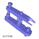 |
| Coolant System Vacuum Refill Kit
HU-919
|
 |
| Cutter, Exhaust Pipe 1, 2
100-051
|
 |
| Engine lifting bracket - Rear 1, 2
303-1141-01
|
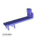 |
| Engine lifting kit 1, 2
303-1141
|
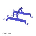 |
| Engine support bracket 1, 2
303-021
|
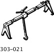 |
| Installer, Oil Seal
308-598
|
 |
| Post Selective Catalyst Reduction Soot Sensor - Remover/Installer
JLR-303-1646
|
 |
| Remover, Driveshaft
205-932
|
 |
| Remover, Input and Output Seal
308-375
|
 |
| Remover/Installer, Driveshaft Nut
JLR-205-993
|
 |
| Remover/Installer, Halfshaft
204-506/1
|
 |
| Remover/Installer, Halfshaft Screw Thread
204-506/3
|
 |
| Remover/Installer, Halfshaft Spacer
204-506/2
|
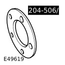 |
| Remover/Installer, NOx/Oxygen Sensor
JLR-303-1666
|
 |
| Retainers, Halfshaft tools
204-506/5
|
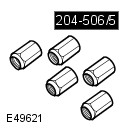 |
| Slide Hammer 1, 2
100-012
|
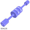 |
| Slide Hammer Adapter
100-012-01
|
 |
| Splitter, Damper
JLR-204-802
|
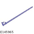 |
| Splitter, Upper Arm
JLR-204-803
|
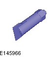 |
| Viscous Coupling Wrench
303-1142
|
 |
| Wrench, H02S
310-121
|
 |
| Wrench, Transmission Filler Plug
307-452
|
 |
| Fuel Injector Removal Adapter
310-213
|
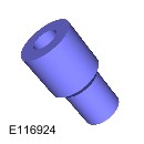 |
| Locking Tool, Flywheel 1, 2
303-1123
|
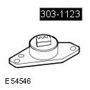 |
| Rear End Accessory Drive (READ) belt Timing Tool
310-212
|
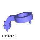 |
| Remover/Installer, Camshaft Rear Pulley 1, 2
JLR-303-1523
|
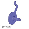 |
PUBLISHED: 28-OCT-2019
2017.0 RANGE ROVER SPORT (LW), 303-01A
ENGINE - TDV6 3.0L DIESEL /TDV6 3.0L DIESEL - GEN 1.5/TDV6 3.0L DIESEL - GEN 2
LONG/STRIPPED ENGINE ASSEMBLY RENEW - TDV6 3.0L DIESEL - GEN 2 - TWIN TURBOCHARGER (G2194109)
- 12.41.02
- STRIPPED ENGINE - REMOVE ENGINE, CHANGE OVER ANCILLARY EQUIPMENT AND REFIT
- 3000 CC, TDV6, TWIN TURBOCHARGER FITTED, DIESEL, WITH PARTICULATE FILTER, WITH DIESEL EXHAUST FL
- 15.90
- USED WITHINS
SPECIAL TOOL(S)

100-012
Slide Hammer
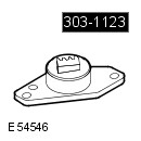
303-1123
Locking Tool, Flywheel

310-213
Fuel Injector Removal Adapter

JLR-303-1523
Remover/Installer, Camshaft Rear Pulley
Before disconnecting any components, make sure the area is clean and free from foreign material. When disconnected all openings must be sealed.
- This procedure contains some variation in the illustrations depending on the vehicle specification, but the essential information is always correct.
- This procedure contains illustrations showing certain components removed to provide extra clarity.
- Remove the engine.
Refer to:Engine (303-01A Engine - TDV6 3.0L Diesel /TDV6 3.0L Diesel - Gen 1.5/TDV6 3.0L Diesel - Gen 2, Removal).
-
Install the special tool.Install the Special Tool(s): 303-1123

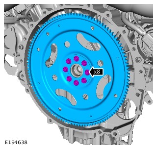
-
Remove the special tool.Remove the Special Tool(s): 303-1123
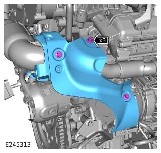
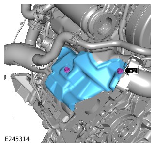
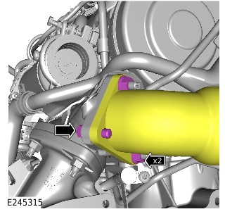
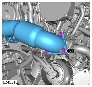
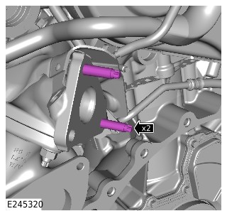
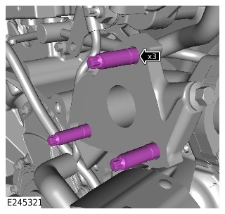
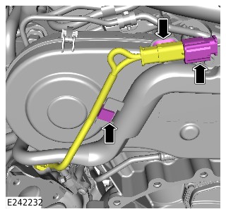
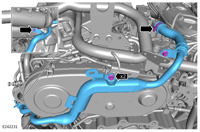
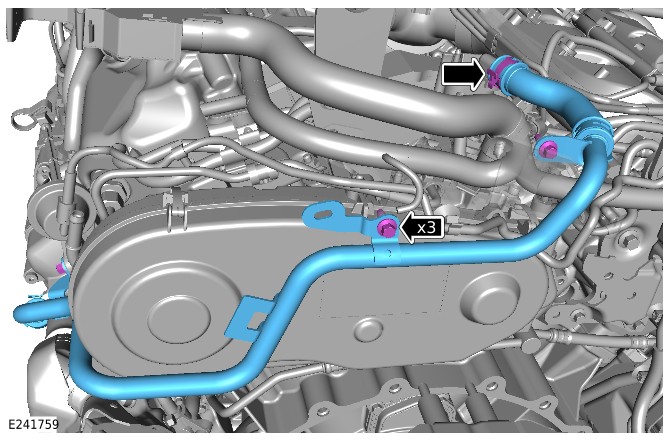
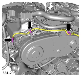
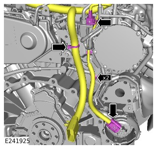
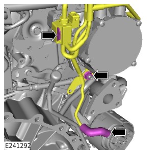
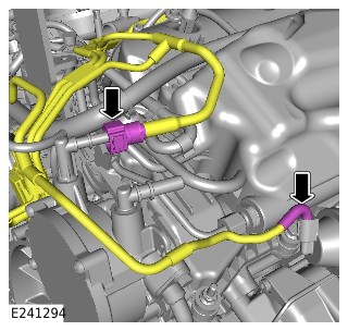
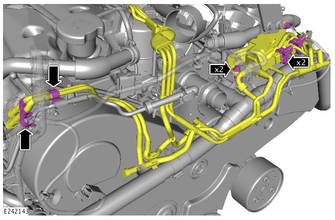
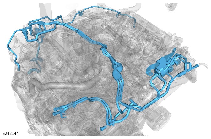
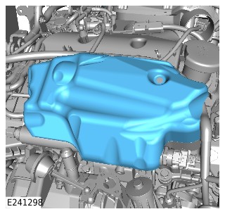
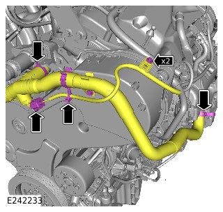
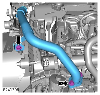
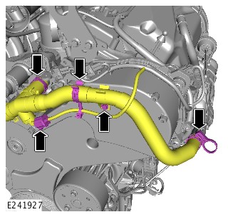
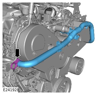
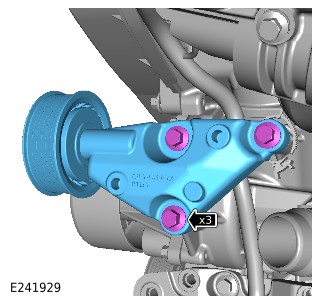
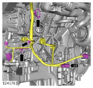
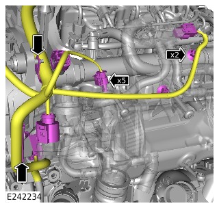
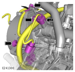
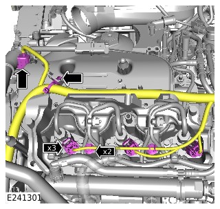
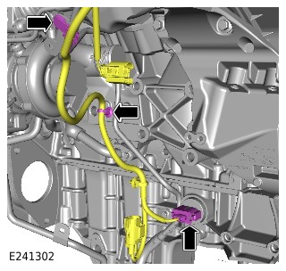
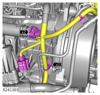
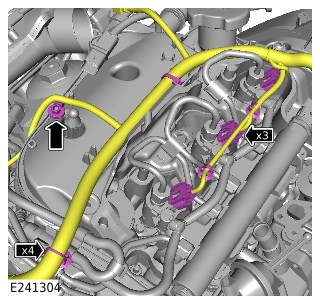
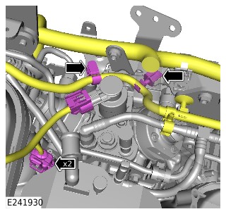
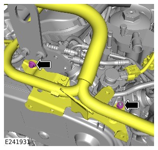
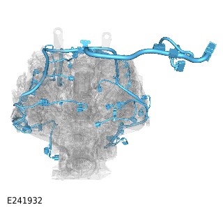
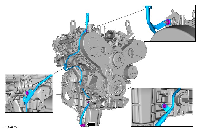
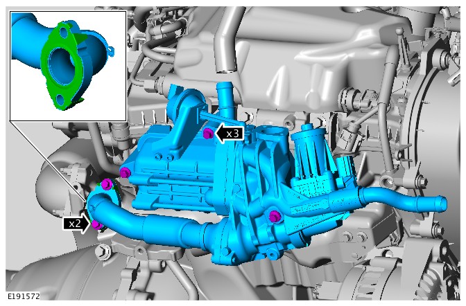
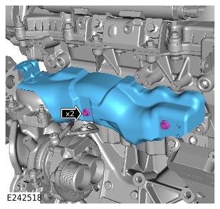
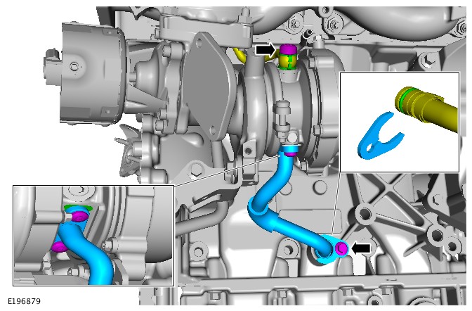
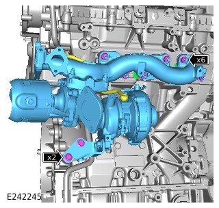
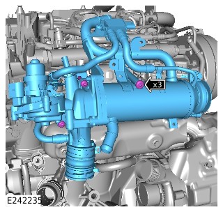
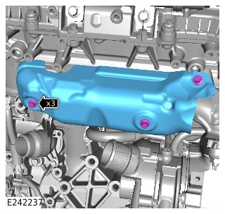
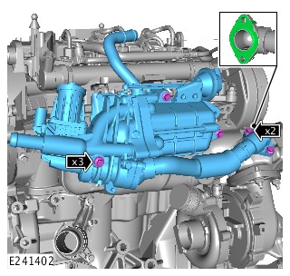
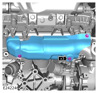
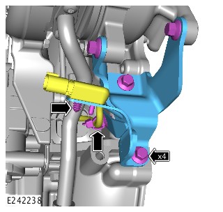
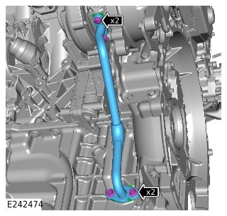
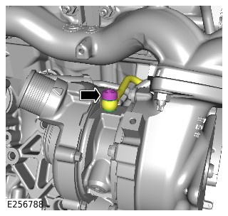
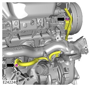
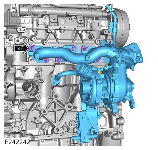

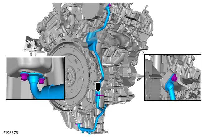
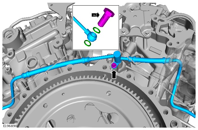
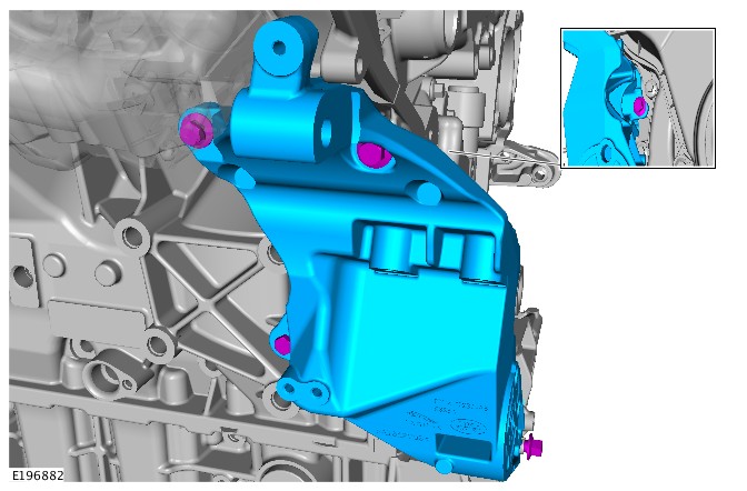
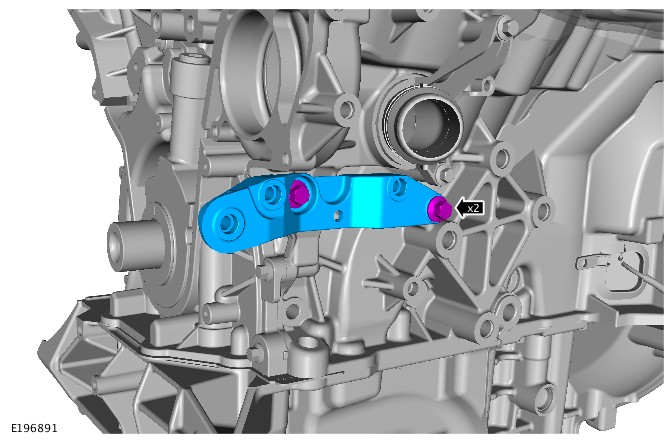
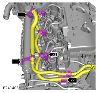
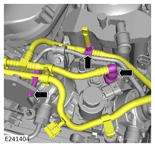
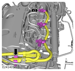
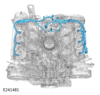
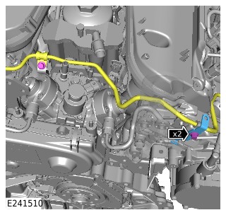
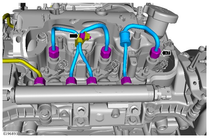
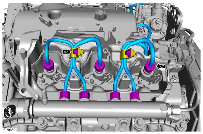
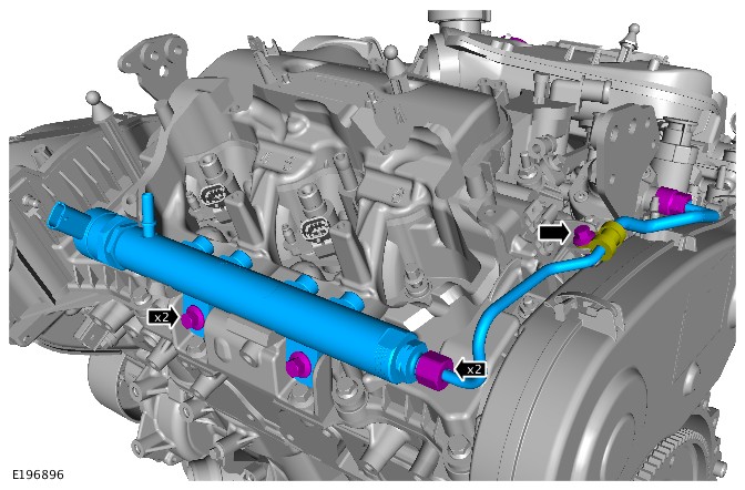
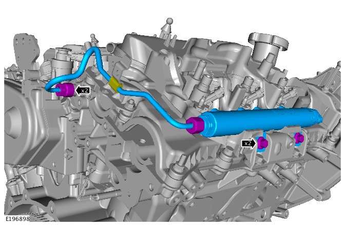
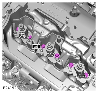
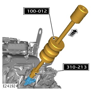

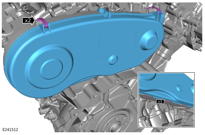
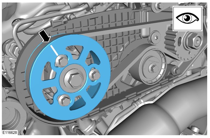


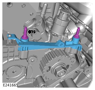
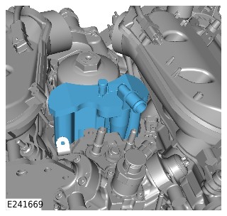
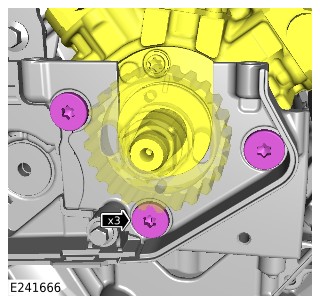
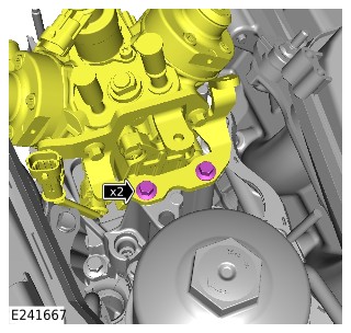
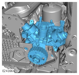
-
Install the special tool.Install the Special Tool(s): JLR-303-1523Torque: 10Nm
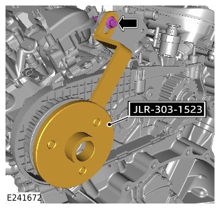
-
- Install the special tool.
Install the Special Tool(s): JLR-303-1523
- Remove and discard the camshaft sprocket bolt.
- Install the special tool.
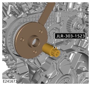
- Remove the special tool.
Remove the Special Tool(s): JLR-303-1523

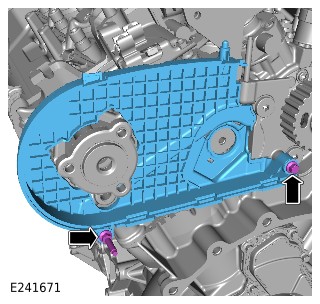
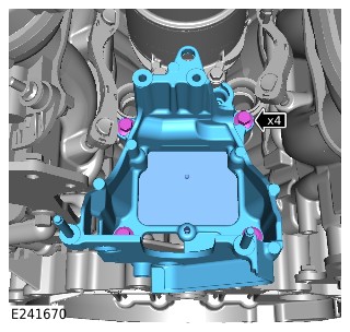
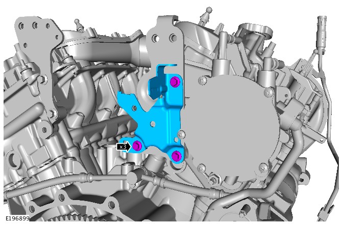
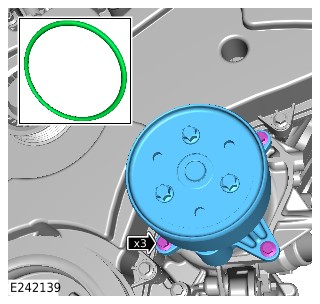
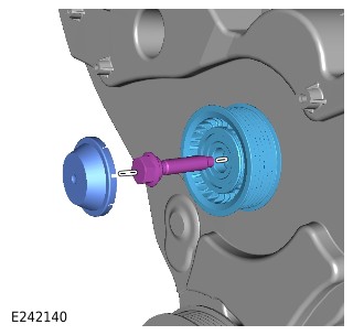
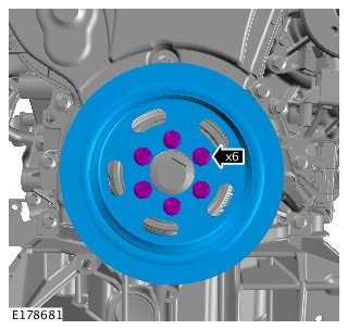
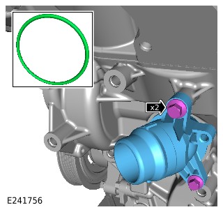
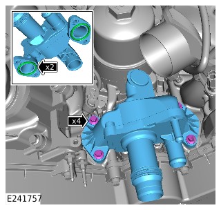
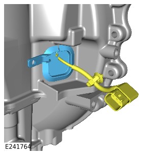
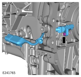
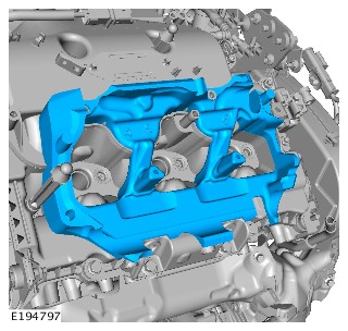
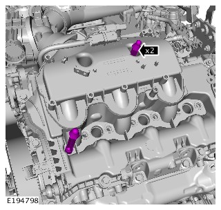
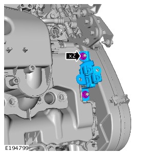
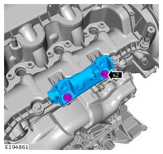
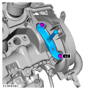
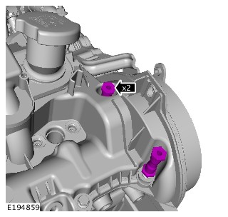
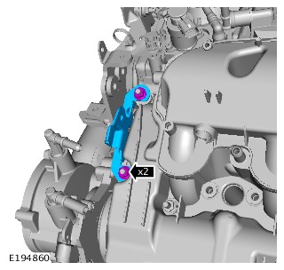
LONG/STRIPPED ENGINE ASSEMBLY RENEW - TDV6 3.0L DIESEL - GEN 2 - TWIN TURBOCHARGER (G2357394)
| Name | Quantity | Part Number |
|---|---|---|
| Camshaft position sensor | 1 | LR013458 |
| Camshaft sprocket bolt | 1 | LR010530 |
| Circlip | 1 | TDL500030 |
| Coolant pump inlet O-ring seal | 1 | 1336551 |
| Driveshaft flange bolts 1, 2 | 4 | TYG500130 |
| Driveshaft flange bolts 1, 2 | 6 | TYG500141 |
| EGR cooler to EGR valve gasket | 1 | LR078958 |
| Engine compartment brace bolts | 8 | LR037935 |
| Engine coolant outlet upper O-ring seal | 2 | LR018829 |
| Engine coolant pump gasket | 1 | LR079619 |
| Exhaust manifold cross-over pipe gaskets | 2 | LR072304 |
| Exhaust manifold cross-over pipe nuts | 6 | LR106277 |
| Exhaust manifold cross-over pipe studs | 6 | LR113358 |
| Exhaust manifold gasket | 2 | 1336543 |
| Exhaust manifold studs | 12 | 1357627 |
| Front halfshaft nut | 1 | LR024151 |
| Front suspension upper arm ball joint to wheel knuckle bolt (s) | 1 | KYG000230 |
| Front suspension upper arm ball joint to wheel knuckle nut (s) | 1 | FY110056 |
| Fuel injector refit kit - cylinder(s) 2,5 or 6 | 3 | LR017437 |
| Fuel injector refit kit - cylinder(s) 3 or 4 | 2 | LR017438 |
| Fuel injector refit kit - cylinder 1 | 1 | LR017436 |
| Fuel pump drive belt kit | 1 | LR069054 |
| Fuel rail balance pipe | 1 | LR013482 |
| Intake air shutoff throttle front seal(s) | 1 | LR008353 |
| Intake air shutoff throttle rear seal(s) | 2 | 1316152 |
| Left exhaust downpipe gasket | 1 | LR016619 |
| Oil pan scavenge reservoir tube O-ring seal(s) | 1 | LR018460 |
| Oil scavenge pipe gasket | 1 | 1331076 |
| Retaining clip | 1 | 1311338 |
| Right exhaust downpipe gasket | 1 | LR016621 |
| Right fuel rail supply pipe | 1 | LR013481 |
| Shock absorber to yoke bolt | 1 | LR000094 |
| Stabilizer bar link retaining nut(s) | 1 | FY114056 |
| Steering column lower shaft lower bolt | 1 | QYG500090 |
| Tie-rod end nut | 1 | LR026275 |
| Torque converter bolts | 4 | LR038661 |
| Transmission fluid cooler tubes to transmission O-ring seals | 2 | LR049457 |
| Turbocharger coolant pipes to turbocharger gasket | 1 | LR062102 |
| Turbocharger oil feed pipe banjo bolt washers | 2 | 1372726 |
| Turbocharger oil return pipe lower gasket | 1 | LR013234 |
| Turbocharger oil return pipe upper gasket | 1 | LR013235 |
| Turbocharger oil supply pipe | 1 | LR038163 |
| Yoke to lower arm bolt (s) | 1 | LR034230 |
| Yoke to lower arm nut | 1 | LR038809 |
| Yoke to shock absorber nut (s) | 1 | FN112056 |
| Name | Quantity | Part Number | VIN range from | VIN range to |
|---|---|---|---|---|
| Driveshaft flange bolts | 6 | LR092696 | HA151411 | |
| Driveshaft flange bolts | 6 | TYP500180 | HA000001 | HA151410 |
| Name | Quantity | Part Number | VIN range from |
|---|---|---|---|
| Engine | 1 | LR035100 | |
| Engine | 1 | LR106166 | FA000001 |
| Engine | 1 | LR048136 | |
| Engine | 1 | LR127427 | FA000001 |
| Name | Quantity | Part Number |
|---|---|---|
| EGR valve outlet pipe gasket (vehicles without EGR cooler) | 1 | LR078915 |
| Name | Quantity | Part Number |
|---|---|---|
| EGR valve outlet pipe gasket (vehicles without EGR cooler) | 2 | LR038333 |
| Name | Quantity | Part Number | VIN range from | VIN range to |
|---|---|---|---|---|
| Diesel exhaust fluid injector clamp kit | 1 | LR138592 | LA580625 | |
| Diesel exhaust fluid injector clamp kit | 1 | LR069697 | LA580624 | |
| Exhaust manifold nuts | 12 | LR004057 | JA193550 | |
| Exhaust manifold nuts | 12 | LR106277 | JA193551 | |
| Exhaust manifold to EGR valve gasket | 2 | LR031488 | FA999999 | |
| Exhaust manifold to EGR valve gasket | 2 | LR075627 | GA000001 | LR031488 |
| Flexplate bolts | 8 | 1406665 | HA146684 | |
| Flexplate bolts | 8 | LR096833 | HA146685 | |
| Left fuel rail supply pipe | 1 | LR013480 | DA999999 | |
| Left fuel rail supply pipe | 1 | LR059808 | EA000001 | |
| Secondary turbocharger oil return pipe | 1 | LR044556 | EA299999 | |
| Secondary turbocharger oil return pipe | 1 | LR044556 | FA516687 | |
| Secondary turbocharger oil return pipe | 1 | LR078522 | EA300000 | FA520408 |
| Secondary turbocharger oil return pipe | 1 | LR078522 | FA516688 | FA520408 |
| Secondary turbocharger oil return pipe | 1 | LR078875 | FA520409 | FA611880 |
| Secondary turbocharger oil return pipe | 1 | LR087351 | FA611881 | |
| Secondary turbocharger oil return pipe upper gasket | 1 | LR078880 | FA516470 | GA999999 |
| Secondary turbocharger oil return pipe upper gasket | 1 | LR087348 | HA000001 | |
| Secondary turbocharger oil return pipe upper gasket | 1 | LR013235 | FA516469 | |
| Turbocharger coolant pipe | 1 | LR061986 | FA000001 | GA110589 |
| Turbocharger coolant pipe | 1 | LR092499 | GA110590 | |
| Turbocharger coolant pipe | 1 | LR061985 | FA000001 | GA587522 |
| Turbocharger coolant pipe | 1 | LR092500 | GA587523 |
| Adapter, Wrench 1, 2
303-1069
|
|
| Adaptor, Cooling System Vacuum Refill Kit
JLR-303-1634
|
|
| Ball Joint Splitter
JLR-204-793A
|
|
| Coolant System Vacuum Refill Kit
HU-919
|
|
| Cutter, Exhaust Pipe 1, 2
100-051
|
|
| Engine lifting bracket - Rear 1, 2
303-1141-01
|
|
| Engine lifting kit 1, 2
303-1141
|
|
| Engine support bracket 1, 2
303-021
|
|
| Installer, Oil Seal
308-598
|
|
| Post Selective Catalyst Reduction Soot Sensor - Remover/Installer
JLR-303-1646
|
|
| Remover, Driveshaft
205-932
|
|
| Remover, Input and Output Seal
308-375
|
|
| Remover/Installer, Driveshaft Nut
JLR-205-993
|
|
| Remover/Installer, Halfshaft
204-506/1
|
|
| Remover/Installer, Halfshaft Screw Thread
204-506/3
|
|
| Remover/Installer, Halfshaft Spacer
204-506/2
|
|
| Remover/Installer, NOx/Oxygen Sensor
JLR-303-1666
|
|
| Retainers, Halfshaft tools
204-506/5
|
|
| Slide Hammer 1, 2
100-012
|
|
| Slide Hammer Adapter
100-012-01
|
|
| Splitter, Damper
JLR-204-802
|
|
| Splitter, Upper Arm
JLR-204-803
|
|
| Viscous Coupling Wrench
303-1142
|
|
| Wrench, H02S
310-121
|
|
| Wrench, Transmission Filler Plug
307-452
|
|
| Fuel Injector Removal Adapter
310-213
|
|
| Locking Tool, Flywheel 1, 2
303-1123
|
|
| Rear End Accessory Drive (READ) belt Timing Tool
310-212
|
|
| Remover/Installer, Camshaft Rear Pulley 1, 2
JLR-303-1523
|
|
PUBLISHED: 28-OCT-2019
2017.0 RANGE ROVER SPORT (LW), 303-01A
ENGINE - TDV6 3.0L DIESEL /TDV6 3.0L DIESEL - GEN 1.5/TDV6 3.0L DIESEL - GEN 2
LONG/STRIPPED ENGINE ASSEMBLY RENEW - TDV6 3.0L DIESEL - GEN 2 - TWIN TURBOCHARGER (G2194109)
- 12.41.02
- STRIPPED ENGINE - REMOVE ENGINE, CHANGE OVER ANCILLARY EQUIPMENT AND REFIT
- 3000 CC, TDV6, TWIN TURBOCHARGER FITTED, DIESEL, WITH PARTICULATE FILTER, WITH DIESEL EXHAUST FL
- 15.90
- USED WITHINS
SPECIAL TOOL(S)
100-012
Slide Hammer
303-1123
Locking Tool, Flywheel
310-213
Fuel Injector Removal Adapter
JLR-303-1523
Remover/Installer, Camshaft Rear Pulley
Before disconnecting any components, make sure the area is clean and free from foreign material. When disconnected all openings must be sealed.
- This procedure contains some variation in the illustrations depending on the vehicle specification, but the essential information is always correct.
- This procedure contains illustrations showing certain components removed to provide extra clarity.
- Remove the engine.
Refer to:Engine (303-01A Engine - TDV6 3.0L Diesel /TDV6 3.0L Diesel - Gen 1.5/TDV6 3.0L Diesel - Gen 2, Removal).
-
Install the special tool.Install the Special Tool(s): 303-1123
-
Remove the special tool.Remove the Special Tool(s): 303-1123
-
Install the special tool.Install the Special Tool(s): JLR-303-1523Torque: 10Nm
-
- Install the special tool.
Install the Special Tool(s): JLR-303-1523
- Remove and discard the camshaft sprocket bolt.
- Install the special tool.
- Remove the special tool.
Remove the Special Tool(s): JLR-303-1523
General Procedures
ENGINE OIL DRAINING AND FILLING (G1509133)
- 12.60.05
- ENGINE OIL DRAINING AND FILLING
- 3000 CC, TDV6
- 0.80
- USED WITHINS
PART(S)
| STEP | PART NAME | QUANTITY |
|---|---|---|
| Filling Step 1 | Oil pan drain plug | 1 |
| Filling Step 5 | Oil filter | 1 |
| Filling Step 5 | Oil filter and O-ring seal kit | 1 |
The spilling of hot engine oil is unavoidable during this procedure, care must be taken to prevent scalding.
Make sure the engine is warm.
Engine oil vacuum draining and filling is the recommended procedure for engine oil change during a scheduled service. Scheduled service labour times are calculated using this method.
-
Refer to:Engine Cover - TDV6 3.0L Diesel /TDV6 3.0L Diesel - Gen 1.5/TDV6 3.0L Diesel - Gen 2 (501-05 Interior Trim and Ornamentation, Removal and Installation).
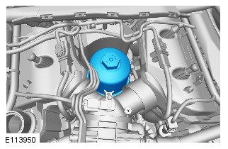

-
Raise and support the vehicle.WARNING:
Make sure to support the vehicle with axle stands.
-
Refer to:Engine Undershield (501-02 Front End Body Panels, Removal and Installation).
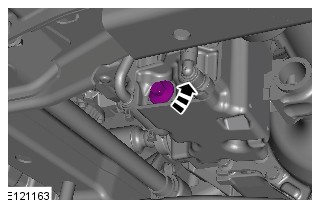
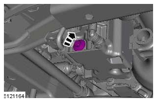
-
Refer to:Engine Undershield (501-02 Front End Body Panels, Removal and Installation).
- Lower the vehicle.
-
CAUTION:
Make sure the engine oil filter housing center tube is installed to the engine oil filter housing before installing the new engine oil filter, as shown in the illustration. Failure to do this will cause low engine oil pressure when starting the engine, resulting in premature engine wear.
Check the position of the center tube.
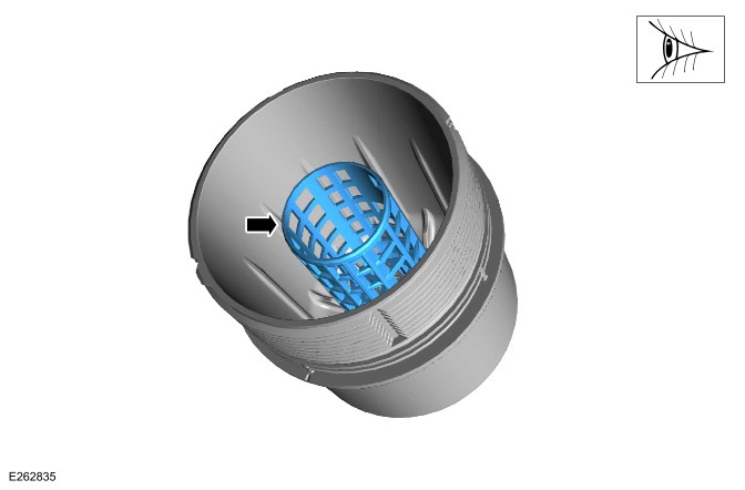
-
Refer to:Engine Cover - TDV6 3.0L Diesel /TDV6 3.0L Diesel - Gen 1.5/TDV6 3.0L Diesel - Gen 2 (501-05 Interior Trim and Ornamentation, Removal and Installation).
-
Fill the engine with the recommended oil to the correct level.Refer to:Specifications (303-01A Engine - TDV6 3.0L Diesel /TDV6 3.0L Diesel - Gen 1.5/TDV6 3.0L Diesel - Gen 2, Specifications).
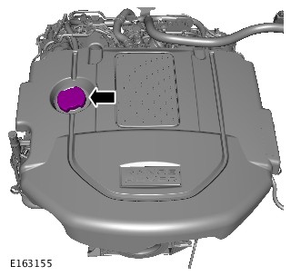
- Clean any residual engine oil from the oil filler cap area.
-
CAUTION:
Make sure that the vehicle has been left for 5 minutes from filling with oil.
- Start the engine and allow to run for 10 minutes, stop the engine.
- Check for leaks.
-
CAUTIONS:
-
Make sure that the selector lever is in the park (P) position.
-
Make sure that the hood is open.
- Set the ignition to the ON position.
-
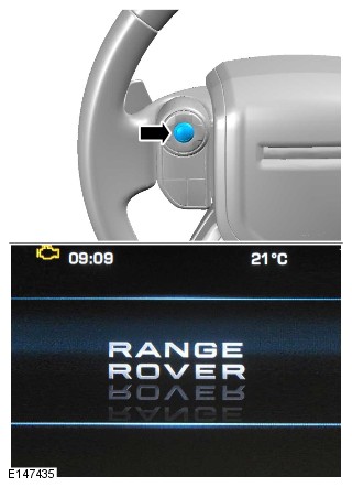
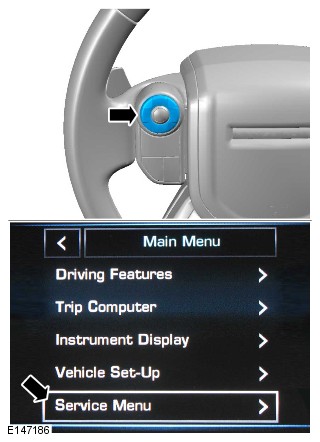
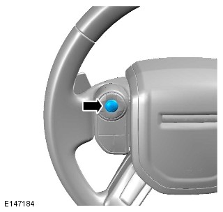
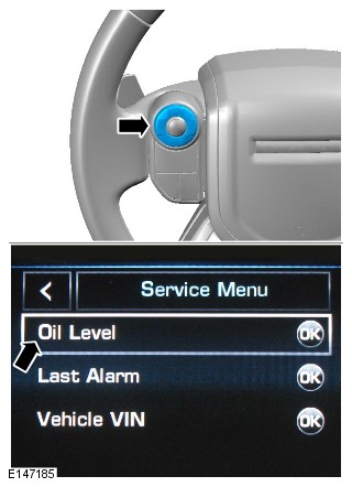
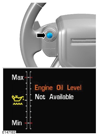
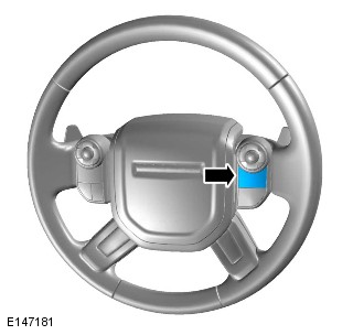

- Set the ignition to the OFF position.
- Allow 10 minutes for the engine oil level to stabilize if there has been additional oil top up.
The following steps are to update the average oil level value.
- Repeat step 11 to 17 to access the oil level display in service mode.
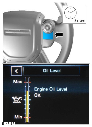
Close the hood.
- Set the ignition to the OFF position.
- Set the ignition to the ON position.
-
- Press the left-hand OK button and follow the instructions.
-
Make sure that the average oil level value has now been updated.NOTE:
If the message shows "Not available” wait for further 10 mins to allow the oil level to stabilize.
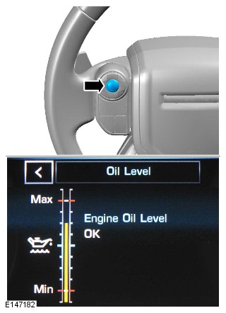
ENGINE OIL VACUUM DRAINING AND FILLING (G1509134)
- 12.60.99
- ENGINE OIL VACUUM DRAIN / REFILL INCLUDING OIL FILTER - RENEW
- 3000 CC, TDV6
- 0.50
- USED WITHINS
SPECIAL TOOL(S)
JLR-303-1644
Oil Extraction Kit
PART(S)
| STEP | PART NAME | QUANTITY |
|---|---|---|
| Filling Step 2 | Oil filter | 1 |
| Filling Step 2 | Oil filter O-ring seal(s) | 1 |
The spilling of hot engine oil is unavoidable during this procedure, care must be taken to prevent scalding.
Make sure the engine is warm.
Engine oil vacuum draining and filling is the recommended procedure for engine oil change during a scheduled service. Scheduled service labour times are calculated using this method.
-
Refer to:Engine Cover - TDV6 3.0L Diesel /TDV6 3.0L Diesel - Gen 1.5/TDV6 3.0L Diesel - Gen 2 (501-05 Interior Trim and Ornamentation, Removal and Installation).

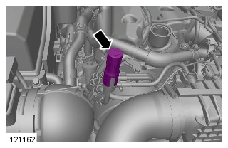
-
NOTE:
Some variation in the illustrations may occur, but the essential information is always correct.
Using the oil vacuum pump drain the oil out through the oil extraction tube.Special Tool(s): JLR-303-1644
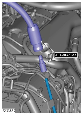
- Remove the oil vacuum pump.
-
CAUTION:
Make sure the engine oil filter housing center tube is installed to the engine oil filter housing before installing the new engine oil filter, as shown in the illustration. Failure to do this will cause low engine oil pressure when starting the engine, resulting in premature engine wear.
Check the position of the center tube.
-
- Fill the engine with the recommended oil to the correct level.
Refer to:Specifications (303-01A Engine - TDV6 3.0L Diesel /TDV6 3.0L Diesel - Gen 1.5/TDV6 3.0L Diesel - Gen 2, Specifications).
- Clean any residual engine oil from the oil filler cap area.
- Fill the engine with the recommended oil to the correct level.
-
Refer to:Engine Cover - TDV6 3.0L Diesel /TDV6 3.0L Diesel - Gen 1.5/TDV6 3.0L Diesel - Gen 2 (501-05 Interior Trim and Ornamentation, Removal and Installation).
-
CAUTION:
Make sure that the vehicle has been left for 5 minutes from filling with oil.
- Start the engine and allow to run for 10 minutes, stop the engine.
- Check for leaks.
-
CAUTIONS:
-
Make sure that the selector lever is in the park (P) position.
-
Make sure that the hood is open.
- Set the ignition to the ON position.
-
- Set the ignition to the OFF position.
- Allow 10 minutes for the engine oil level to stabilize if there has been additional oil top up.
The following steps are to update the average oil level value.
- Repeat step 8 to 14 to access the oil level display in service mode.
Close the hood.
- Set the ignition to the OFF position.
- Set the ignition to the ON position.
ACTIVE ENGINE MOUNT - VACUUM CHECK (G2782711)
- 12.45.50
- ACTIVE ENGINE MOUNT - VACUUM CHECK
- 3000 CC, TDV6
- 0.70
- USED WITHINS
GENERAL EQUIPMENT
| EQUIPMENT NAME |
|---|
| Jaguar Land Rover approved battery support unit |
| Jaguar Land Rover approved diagnostic equipment |
-
- If the engine management lamp ON, continue to step 1 of the repair section of this procedure.
- If the engine management lamp is NOT ON, continue to step 2.
- Raise and support the vehicle on a suitable 2 post lift.
Refer to:Jacking and Lifting (100-02, Description and Operation).
- Open the hood.

-
- Using the Jaguar Land Rover approved vacuum testing equipment, connect to the vacuum pipe and check that the active engine mounts hold vacuum. The engine mounts should generate a vacuum of 0.4 bar and then be able to hold the vacuum for 30 seconds.
- If the active engine mount holds vacuum for 30 seconds, continue to step 1 of the repair section of this procedure.
- If the active engine mounts does not hold vacuum for 30 seconds, continue to step 6.
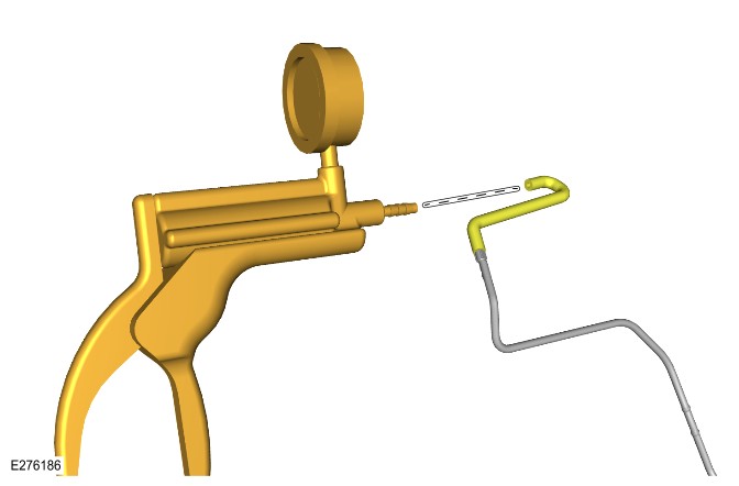
- Remove the engine undershield.
Refer to:Engine Undershield (501-02, Removal and Installation).
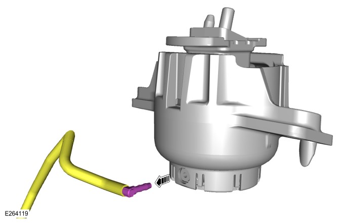
-
- Inspect the right active engine mount switch positions.
- If the right active engine mount switch clearly is not visible as shown in illustration E222279, continue to step 9.
- If the right active engine mount switch is clearly visible as shown in illustration E222279, replace the right active engine mount and continue to step 11.
Refer to:Right Engine Mount (303-01A, Removal and Installation).
-
- Using the Jaguar Land Rover approved vacuum testing equipment, connect to the right active engine mount and check that the active engine mount holds vacuum. The engine mount should generate a vacuum of 0.4 bar and then be able to hold the vacuum for 30 seconds.
- If the right active engine mount holds vacuum for 30 seconds, continue to step 10.
- If the right active engine mount does not hold vacuum for 30 seconds, replace the right active engine mount and continue to step 11.
Refer to:Right Engine Mount (303-01A, Removal and Installation).
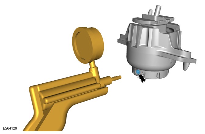
-
NOTE:
Check the vacuum pipe(s) and connections are tight and there are no signs of leakage.
- Disconnect the vacuum line.
- Connect the Jaguar Land Rover approved vacuum testing equipment to the left vacuum pipe.
- Using the Jaguar Land Rover approved vacuum testing equipment, check that the left active engine mount holds vacuum. The engine mount should generate a vacuum of 0.4 bar and then be able to hold the vacuum for 30 seconds.
- If the left active engine mount holds vacuum for 30 seconds, continue to step 12.
- If the left active engine mount does not hold vacuum for 30 seconds, replace the right active engine mount and vacuum pipe and continue to step 13.
Refer to:Right Engine Mount (303-01A, Removal and Installation).

-
- Install the engine undershield.
Refer to:Engine Undershield (501-02, Removal and Installation).
- Lower the vehicle
- The active engine mount vacuum check is complete and the active engine mounts have passed, continue to step 1 of the repair section of this procedure if fault is still persisting.
- Install the engine undershield.


-
- Connect the Jaguar Land Rover (JLR) approved battery support unit.
General Equipment: Jaguar Land Rover approved battery support unit
- Connect the JLR approved diagnostic equipment.
General Equipment: Jaguar Land Rover approved diagnostic equipment
- Read the Diagnostic Trouble Code(s) (DTC) in the Powertrain Control Module (PCM).
- Connect the Jaguar Land Rover (JLR) approved battery support unit.
-
- If DTC P0A14-13 Engine Mount "A" Control Circuit/Open - Circuit open, continue to step 26.
- If DTC P0A15-11 Engine Mount "A" Control Circuit Low - Circuit short to ground, continue to step 27.
- If DTC P0A16-12 Engine Mount "A" Control Circuit High - Circuit short to battery, continue to step 28.
- If DTC P0A16-4B Engine Mount "A" Control Circuit High - Over temperature, continue to step 29.
- If none of the above DTC are present, continue to step 30 and replace the active engine mount solenoid.
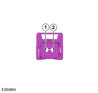
-
- Illustration E264864 shows the connector pin number location. Using a multi meter connect the positive probe to the back of pin 1 connector C1E925-1 and the negative probe to body ground
- If a fault is present refer to wiring diagram 303-14 Electronic Engine Controls. Check the wiring between connectors C1E925-1 and C1BB03AD-7, then check the wring between connectors C1E925-2 and connector C1E116BD-91. Repair wiring harness, clear the DTC and retest.
Refer to:Wiring Harness Overlay (418-02 Wiring Harnesses, Description and Operation).
- If there is not a fault with the wiring continue step 30 and replace the active engine mount solenoid.
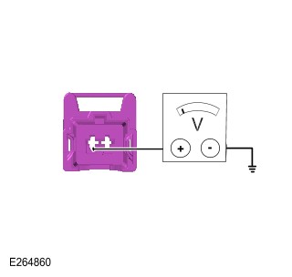
-
- Illustration E264864 shows the connector pin number location. Using a multi meter connect the positive probe to the back of pin 1 connector C1E925-1 and the negative probe to body ground.
- If a fault is present refer to wiring diagram 303-14 Electronic Engine Controls. Check the wiring between connector C1E925-1 and C1BB03AD-7, then check the wiring between connectors C1E925-2 and C1E116BD-91. Repair the wiring harness, clear the DTC and retest.
Refer to:Wiring Harness Overlay (418-02 Wiring Harnesses, Description and Operation).
- If there is not a fault with the wiring continue step 9 and replace the active engine mount solenoid.
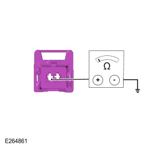
-
- Illustration E264864 shows the connector pin number location. Using a multi meter connect the positive probe to the back of connector C1E925-2 pin 2 and the negative probe to the connector pin terminal C1E116BD-91 and check for voltage .
- If a fault is present refer to wiring diagram 303-14 Electronic Engine Controls. Check the wiring between connectors C1E925-1 and C1BB03AD-7, then check the wiring between connectors C1E925-2 and C1E116BD-91. Repair the wiring harness, clear the DTC and retest.
Refer to:Wiring Harness Overlay (418-02 Wiring Harnesses, Description and Operation).
- If there is not a fault with the wiring continue step 9 and replace the active engine mount solenoid.
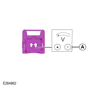
-
- Illustration E264864 shows the connector pin number location. Using a multi meter connect the positive probe to the back of pin 2 C1E925-2 and the negative probe to body ground. .
- If a fault is present refer to wiring diagram 303-14 Electronic Engine Controls. Check the wiring between connectors C1E925-1 and C1BB03AD-7, then check the wiring between connectors C1E925-2 and C1E116BD-91. Repair the wiring harness, clear theDTC and retest.
Refer to:Wiring Harness Overlay (418-02 Wiring Harnesses, Description and Operation).
- If there is not a fault with the wiring continue step 9 and replace the active engine mount solenoid.
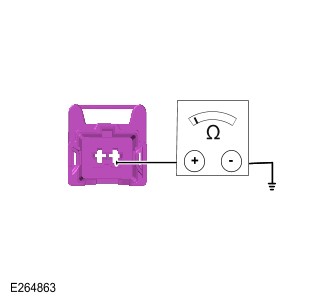
Removal and Installation
LEFT CAMSHAFT (G1509135)
- 12.13.21
- CAMSHAFTS - LH BANK - RENEW
- 3000 CC, TDV6
- 8.80
- USED WITHINS
SPECIAL TOOL(S)
303-1124
Holding Tool, Camshaft Front Pulley

303-1145/2
Remover, Camshaft Rear Pulley Bolt
JLR-303-1523
Remover/Installer, Camshaft Rear Pulley
PART(S)
| STEP | PART NAME | QUANTITY |
|---|---|---|
| Installation Step 4 | Camshaft seal | 1 |
| Installation Step 15 | Camshaft sprocket bolt | 1 |
-
Refer to:Specifications (414-00 Battery and Charging System - General Information, Specifications).
-
Refer to:Rear End Accessory Drive (303-05A Accessory Drive - TDV6 3.0L Diesel /TDV6 3.0L Diesel - Gen 1.5/TDV6 3.0L Diesel - Gen 2, Removal and Installation).
-
Refer to:Timing Belt (303-01A Engine - TDV6 3.0L Diesel /TDV6 3.0L Diesel - Gen 1.5/TDV6 3.0L Diesel - Gen 2, Removal and Installation).
-
Install the special tool.Special Tool(s): JLR-303-1523

-
Install the special tool.Special Tool(s): JLR-303-1523

-
Using the special tool, remove and discard the rear camshaft pulley retaining bolt.Special Tool(s): 303-1145/2

- Remove the special tools.

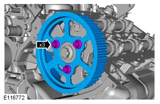
-
Install the special tool.Special Tool(s): 303-1124
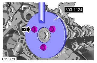
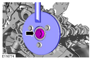
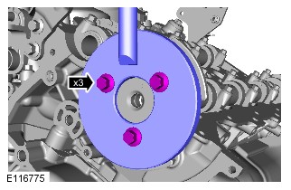
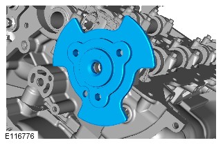
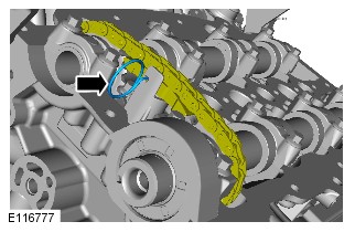

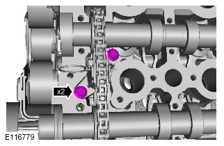
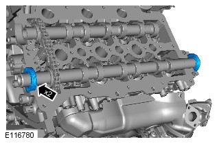
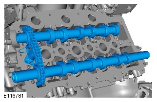
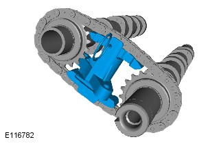
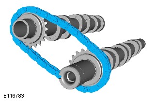
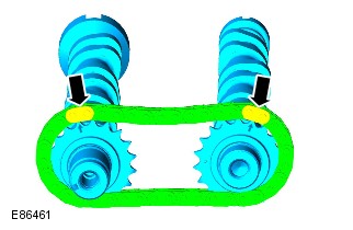
-
CAUTION:
Make sure that the dots on the camshafts are aligned at the 12 o'clock position. Failure to follow this instruction may result in damage to the engine.
NOTES:-
Lubricate the camshafts and the camshaft bearing caps with oil meeting Jaguar specification prior to installation.
-
Use hypoid oil to lubricate the camshafts.
Install the camshafts. -


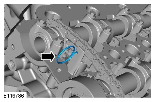

-
CAUTION:
Failure to use special tool JLR-303-1523 might result in engine damage/failure.
Install the special tool.Special Tool(s): JLR-303-1523
-
Install the special tool.Special Tool(s): JLR-303-1523
-
CAUTION:
Make sure the torque wrench setting procedure is followed correctly. Failure to follow this instruction may result in damage to the vehicle.
- Calculate the setting for the torque wrench:
- Stage 1: Multiply the required torque by the effective length of the torque wrench (1).
- Stage 2: Add the effective length of the special tool (2) to the effective length of the torque wrench.
- Stage 3: Divide the total of stage 1 by the total of stage 2.
- Stage 4: Set the torque wrench to the figure arrived at in stage 3.

-
CAUTION:
Make sure the torque wrench setting procedure is followed correctly. Failure to follow this instruction may result in damage to the vehicle.
- Using the special tool, install the camshaft rear pulley retaining bolt.
- Stage one: Tighten to 80 Nm (59 lb.ft).
- Stage two: Tighten a further 80 degrees.
- Remove the special tools.
-
Refer to:Timing Belt (303-01A Engine - TDV6 3.0L Diesel /TDV6 3.0L Diesel - Gen 1.5/TDV6 3.0L Diesel - Gen 2, Removal and Installation).
-
Refer to:Rear End Accessory Drive (303-05A Accessory Drive - TDV6 3.0L Diesel /TDV6 3.0L Diesel - Gen 1.5/TDV6 3.0L Diesel - Gen 2, Removal and Installation).
-
Refer to:Specifications (414-00 Battery and Charging System - General Information, Specifications).
RIGHT CAMSHAFT (G1509136)
- 12.13.20
- CAMSHAFTS - RH BANK - RENEW
- 3000 CC, TDV6
- 6.50
- USED WITHINS
SPECIAL TOOL(S)
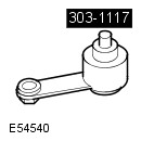
303-1117
Timing Peg, Automatic Transmission
303-1124
Holding Tool, Camshaft Front Pulley
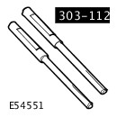
303-1126
Timing Peg, Camshaft Pulley
PART(S)
| STEP | PART NAME | QUANTITY |
|---|---|---|
| Installation Step 4 | Camshaft seal | 1 |
| Installation Step 15 | Timing belt and tensioner kit | 1 |
| Installation Step 25 | Timing belt cover gasket | 1 |
| Installation Step 26 | Engine coolant pump pulley bolts | 1 |
- Disconnect the battery ground cable.
Refer to:Specifications (414-00 Battery and Charging System - General Information, Specifications).
-
Raise and support the vehicle.WARNING:
Make sure to support the vehicle with axle stands.
-
Refer to:Starter Motor (303-06A Starting System - TDV6 3.0L Diesel /TDV6 3.0L Diesel - Gen 1.5/TDV6 3.0L Diesel - Gen 2, Removal and Installation).
-
Refer to:Brake Vacuum Pump - TDV6 3.0L Diesel /TDV6 3.0L Diesel - Gen 1.5/TDV6 3.0L Diesel - Gen 2 (206-07 Power Brake Actuation, Removal and Installation).
-
Refer to:Right Valve Cover (303-01A Engine - TDV6 3.0L Diesel /TDV6 3.0L Diesel - Gen 1.5/TDV6 3.0L Diesel - Gen 2, Removal and Installation).

- Rotate the crankshaft clockwise to align the crankshaft alignment hole in the flywheel or flexplate with the block aperture.

-
Install the special tool.Special Tool(s): 303-1117


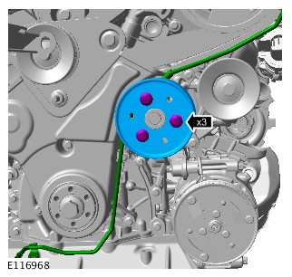
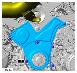

-
Special Tool(s): 303-1126
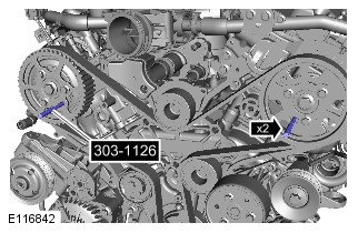


-
Install the special tool.Special Tool(s): 303-1124


-
Remove the special tool.Special Tool(s): 303-1124
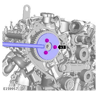

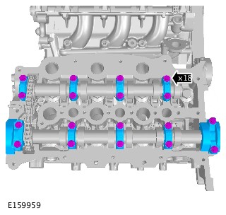
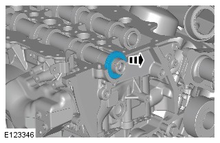
-
CAUTION:
Make sure that the dots on the camshafts are aligned at the 12 o'clock position. Failure to follow this instruction may result in damage to the engine.
NOTES:-
Lubricate the camshafts and the camshaft bearing caps with oil meeting Jaguar specification prior to installation.
-
Use hypoid oil to lubricate the camshafts.
Install the camshafts. -
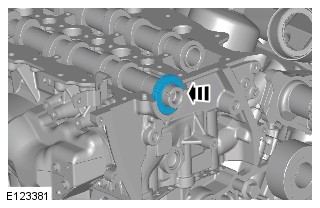
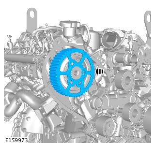
-
Install the special tool.Special Tool(s): 303-1124
-
Remove the special tool.Special Tool(s): 303-1124
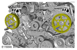

-
CAUTION:
Make sure the camshaft pulleys remain in the clockwise position.
- Install the new timing belt.
- Starting at the crankshaft pulley, install the timing belt in a counter-clockwise direction, in the sequence shown.
- Stage one: Attach the timing belt to the crankshaft pulley.
- Stage two: Attach the timing belt to the idler pulley.
- Stage three: Attach the timing belt to the left-hand camshaft pulley.
- Stage four: Attach the timing belt to the idler pulley.
- Stage five: Attach the timing belt to the RH camshaft pulley.
- Stage six: Attach the timing belt to the timing belt tensioner.


-
Remove the special tool.Special Tool(s): 303-1126
-
Remove the special tool.Special Tool(s): 303-1117
-
Rotate the engine two complete turns clockwise.CAUTION:
Only rotate the crankshaft clockwise.
-
Install with the special tool.Special Tool(s): 303-1117
-
- Install the special tools to the exhaust camshaft pulleys.
Special Tool(s): 303-1126
- If the special tool does not fit correctly, repeat the timing belt installation procedure.
- Remove the special tools from the camshaft pulleys.
- Install the special tools to the exhaust camshaft pulleys.
-
Remove the special tool.Special Tool(s): 303-1117
-
Refer to:Right Valve Cover (303-01A Engine - TDV6 3.0L Diesel /TDV6 3.0L Diesel - Gen 1.5/TDV6 3.0L Diesel - Gen 2, Removal and Installation).
-
Refer to:Brake Vacuum Pump - TDV6 3.0L Diesel /TDV6 3.0L Diesel - Gen 1.5/TDV6 3.0L Diesel - Gen 2 (206-07 Power Brake Actuation, Removal and Installation).
-
Refer to:Starter Motor (303-06A Starting System - TDV6 3.0L Diesel /TDV6 3.0L Diesel - Gen 1.5/TDV6 3.0L Diesel - Gen 2, Removal and Installation).
- Disconnect the battery ground cable.
Refer to:Specifications (414-00 Battery and Charging System - General Information, Specifications).
CAMSHAFT FRONT SEAL (G1509137)
- 12.13.12
- OIL SEALS - FRONT - CAMSHAFTS - PAIR - RENEW
- 3000 CC, TDV6
- 3.10
- USED WITHINS
SPECIAL TOOL(S)
303-1118
Remover, Camshaft Seal

303-1119
Installer, Camshaft Seal
303-1124
Holding Tool, Camshaft Front Pulley
303-1126
Timing Peg, Camshaft Pulley
Some variation in the illustrations may occur, but the essential information is always correct.
-
Refer to:Specifications (414-00 Battery and Charging System - General Information, Specifications).
-
Refer to:Timing Belt (303-01A Engine - TDV6 3.0L Diesel /TDV6 3.0L Diesel - Gen 1.5/TDV6 3.0L Diesel - Gen 2, Removal and Installation).
-
CAUTION:
Do not use the special tools to lock the camshafts. Failure to follow this instruction may result in damage to the engine or the special tools.
Special Tool(s): 303-1126
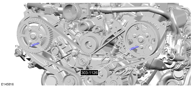
-
Special Tool(s): 303-1124
-
Special Tool(s): 303-1124
-
CAUTION:
Make sure the special tool is correctly seated behind the camshaft seal. Failure to follow this instruction may result in damage to the special tool.
Special Tool(s): 303-1118
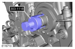
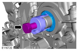
-
Special Tool(s): 303-1119
-
CAUTIONS:
-
Make sure the seal is installed correctly.
-
Make sure that the mating faces are clean and free of corrosion and foreign material.
-
Do not use any lubricant on the camshaft front seal or the camshaft. Failure to follow this instruction may result in damage to the vehicle.
NOTE:Make sure that the seal is 1mm below the face of the cylinder head.
-
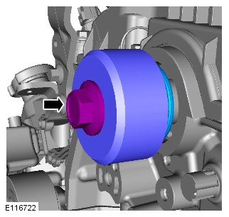
-
Special Tool(s): 303-1119
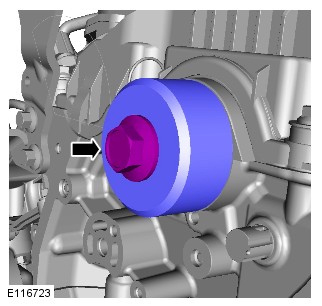
-
Special Tool(s): 303-1124
-
Special Tool(s): 303-1124
-
CAUTION:
Do not use the special tools to lock the camshafts. Failure to follow this instruction may result in damage to the engine or the special tools.
Special Tool(s): 303-1126
-
Refer to:Timing Belt (303-01A Engine - TDV6 3.0L Diesel /TDV6 3.0L Diesel - Gen 1.5/TDV6 3.0L Diesel - Gen 2, Removal and Installation).
-
Refer to:Specifications (414-00 Battery and Charging System - General Information, Specifications).
- 12.13.06
- OIL SEAL - REAR - CAMSHAFT - RENEW
- 3000 CC, TDV6
- 3.10
- USED WITHINS
SPECIAL TOOL(S)
303-1145/2
Remover, Camshaft Rear Pulley Bolt
PART(S)
| STEP | PART NAME | QUANTITY |
|---|---|---|
| Installation Step 4 | Camshaft sprocket bolt | 1 |
Some variation in the illustrations may occur, but the essential information is always correct.
-
Refer to:Rear End Accessory Drive (303-05A Accessory Drive - TDV6 3.0L Diesel /TDV6 3.0L Diesel - Gen 1.5/TDV6 3.0L Diesel - Gen 2, Removal and Installation).
-
Using the special tool, remove and discard the rear camshaft pulley retaining bolt.Special Tool(s): 303-1145/2
- Remove the special tools.
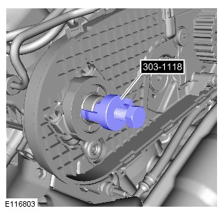
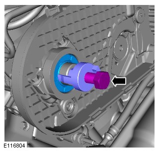
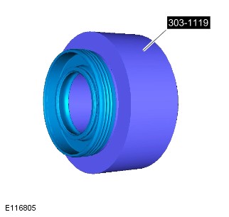
-
CAUTIONS:
-
Make sure the seal is installed correctly.
-
Make sure that the mating faces are clean and free of corrosion and foreign material.
-
Do not use any lubricant on the camshaft rear seal or the camshaft. Failure to follow this instruction may result in damage to the vehicle.
NOTE:Make sure that the seal is 1mm below the face of the cylinder head.
-
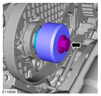
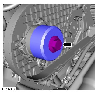
-
CAUTION:
Make sure the torque wrench setting procedure is followed correctly. Failure to follow this instruction may result in damage to the vehicle.
- Calculate the setting for the torque wrench.
- Stage 1: Multiply the required torque by the effective length of the torque wrench (1).
- Stage 2: Add the effective length of the special tool (2) to the effective length of the torque wrench.
- Stage 3: Divide the total of stage 1 by the total of stage 2.
- Stage 4: Set the torque wrench to the figure arrived at in stage 3.
-
CAUTION:
Make sure the torque wrench setting procedure is followed correctly. Failure to follow this instruction may result in damage to the vehicle.
- Using the special tool, install the camshaft rear pulley retaining bolt.
- Stage one: Tighten to 80 Nm (59 lb.ft).
- Stage two: Tighten a further 80 degrees
CAMSHAFT REAR SEAL (G1509138)
- 12.13.06
- OIL SEAL - REAR - CAMSHAFT - RENEW
- 3000 CC, TDV6
- 3.10
- USED WITHINS
SPECIAL TOOL(S)
303-1145/2
Remover, Camshaft Rear Pulley Bolt
PART(S)
| STEP | PART NAME | QUANTITY |
|---|---|---|
| Installation Step 4 | Camshaft sprocket bolt | 1 |
Some variation in the illustrations may occur, but the essential information is always correct.
-
Refer to:Rear End Accessory Drive (303-05A Accessory Drive - TDV6 3.0L Diesel /TDV6 3.0L Diesel - Gen 1.5/TDV6 3.0L Diesel - Gen 2, Removal and Installation).
-
Using the special tool, remove and discard the rear camshaft pulley retaining bolt.Special Tool(s): 303-1145/2
- Remove the special tools.
-
CAUTIONS:
-
Make sure the seal is installed correctly.
-
Make sure that the mating faces are clean and free of corrosion and foreign material.
-
Do not use any lubricant on the camshaft rear seal or the camshaft. Failure to follow this instruction may result in damage to the vehicle.
NOTE:Make sure that the seal is 1mm below the face of the cylinder head.
-
-
CAUTION:
Make sure the torque wrench setting procedure is followed correctly. Failure to follow this instruction may result in damage to the vehicle.
- Calculate the setting for the torque wrench.
- Stage 1: Multiply the required torque by the effective length of the torque wrench (1).
- Stage 2: Add the effective length of the special tool (2) to the effective length of the torque wrench.
- Stage 3: Divide the total of stage 1 by the total of stage 2.
- Stage 4: Set the torque wrench to the figure arrived at in stage 3.
-
CAUTION:
Make sure the torque wrench setting procedure is followed correctly. Failure to follow this instruction may result in damage to the vehicle.
- Using the special tool, install the camshaft rear pulley retaining bolt.
- Stage one: Tighten to 80 Nm (59 lb.ft).
- Stage two: Tighten a further 80 degrees.
-
Refer to:Rear End Accessory Drive (303-05A Accessory Drive - TDV6 3.0L Diesel /TDV6 3.0L Diesel - Gen 1.5/TDV6 3.0L Diesel - Gen 2, Removal and Installation).
CRANKSHAFT FRONT SEAL - TDV6 3.0L DIESEL - GEN 2 (G1875415)
- 12.21.14
- CRANKSHAFT FRONT OIL SEAL - RENEW
- 3000 CC, TDV6, GEN 2
- 2.90
- USED WITHINS
SPECIAL TOOL(S)
303-1120
Remover, Crankshaft Front Seal
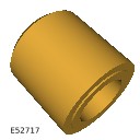
303-1121A
Installer, Crankshaft Seal
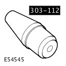
303-1122
Installer, Crankshaft Front Seal
303-1123
Locking Tool, Flywheel
PART(S)
| STEP | PART NAME | QUANTITY |
|---|---|---|
| Installation Step 1 | Crankshaft front oil seal | 1 |
-
Some variation in the illustrations may occur, but the essential information is always correct.
-
Some components shown removed for clarity.
-
Raise and support the vehicle.WARNING:
Make sure to support the vehicle with axle stands.
- Disconnect the battery ground cable.
Refer to:Specifications (414-00 Battery and Charging System - General Information, Specifications).
- Remove the timing belt.
Refer to:Timing Belt (303-01A Engine - TDV6 3.0L Diesel /TDV6 3.0L Diesel - Gen 1.5/TDV6 3.0L Diesel - Gen 2, Removal and Installation).Refer to:Timing Belt (303-01A Engine - TDV6 3.0L Diesel /TDV6 3.0L Diesel - Gen 1.5/TDV6 3.0L Diesel - Gen 2, Removal and Installation).
-
Install the special tool.Special Tool(s): 303-1123
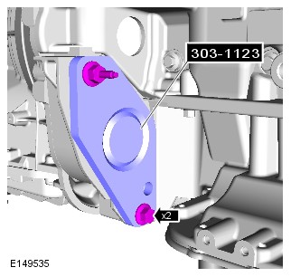
- Remove the crankshaft pulley.
Refer to:Crankshaft Pulley - TDV6 3.0L Diesel - Gen 2 (303-01A Engine - TDV6 3.0L Diesel /TDV6 3.0L Diesel - Gen 1.5/TDV6 3.0L Diesel - Gen 2, Removal and Installation).
-
Install the special tool to the crankshaft.Special Tool(s): 303-1120
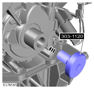
-
Install the special tool to the crankshaft, rotate the special tool to engage the crankshaft front oil seal as shown.Special Tool(s): 303-1120
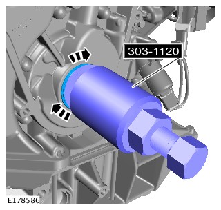
-
Rotate the special tool release bolt.Special Tool(s): 303-1120

-
Using the special tool, remove and discard the crankshaft front oil seal.Special Tool(s): 303-1120
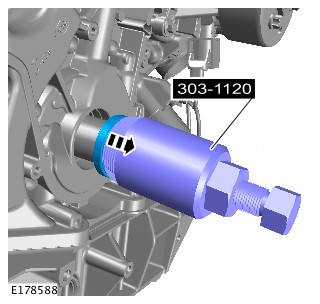
-
CAUTION:
Do not use any lubricant on the crankshaft front seal, special tools or the crankshaft. Failure to follow this instruction may result in damage to the vehicle.
NOTE:Make sure that all the component mating faces are clean.
Install a new crankshaft front seal to the special tool.Special Tool(s): 303-1122
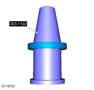
-
Reposition the crankshaft front seal along the special tool.Special Tool(s): 303-1122
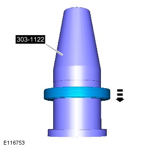
-
Install the special tool to the crankshaft.Special Tool(s): 303-1122
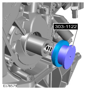
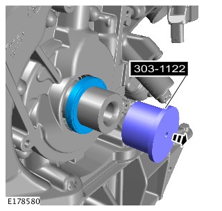
-
Install the special tool to the crankshaft.Special Tool(s): 303-1121A
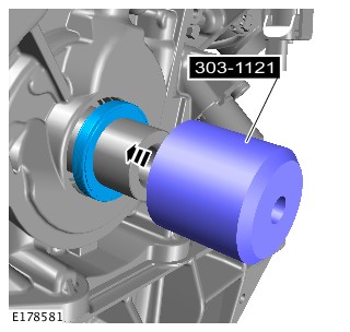
-
NOTES:
-
Make sure the seal is installed correctly.
-
Use the crankshaft bolt with the service tool.
Using the special tool, install the crankshaft front oil seal.Special Tool(s): 303-1121A -
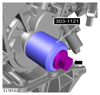
-
CAUTION:
Make sure the seal is installed correctly.
NOTE:Wait 10 seconds before removing the crankshaft seal installation tool.
Remove the special tool.Special Tool(s): 303-1121A
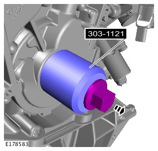
- Install the crankshaft pulley.
Refer to:Crankshaft Pulley - TDV6 3.0L Diesel - Gen 2 (303-01A Engine - TDV6 3.0L Diesel /TDV6 3.0L Diesel - Gen 1.5/TDV6 3.0L Diesel - Gen 2, Removal and Installation).
-
Remove the special tool.Special Tool(s): 303-1123
- Install the timing belt.
Refer to:Timing Belt (303-01A Engine - TDV6 3.0L Diesel /TDV6 3.0L Diesel - Gen 1.5/TDV6 3.0L Diesel - Gen 2, Removal and Installation).
- Connect the battery ground cable.
Refer to:Specifications (414-00 Battery and Charging System - General Information, Specifications).
CRANKSHAFT PULLEY - TDV6 3.0L DIESEL - GEN 2 (G1875416)
- 12.21.01
- CRANKSHAFT PULLEY - RENEW
- 3000 CC, TDV6, GEN 2
- 2.90
- USED WITHINS
SPECIAL TOOL(S)
303-1117
Timing Peg, Automatic Transmission
303-1123
Locking Tool, Flywheel
303-D121
Puller, General Purpose
PART(S)
| STEP | PART NAME | QUANTITY |
|---|---|---|
| Installation Step 2 | Crankshaft pulley bolt | 1 |
| Installation Step 7 | Crankshaft mass damper bolt(s) | 6 |
-
This procedure contains some variation in the illustrations depending on the vehicle specification, but the essential information is always correct.
-
This procedure contains illustrations showing certain components removed to provide extra clarity.
- Raise and support the vehicle on a suitable 2 post lift.
Refer to:Lifting (100-02 Jacking and Lifting, Description and Operation).
- Disconnect the startup battery ground cable.
Refer to:Specifications (414-00 Battery and Charging System - General Information, Specifications).
- Remove the timing belt.
Refer to:Timing Belt (303-01A Engine - TDV6 3.0L Diesel /TDV6 3.0L Diesel - Gen 1.5/TDV6 3.0L Diesel - Gen 2, Removal and Installation).
-
- Remove the special tool.
-
Special Tool(s): 303-1117
-
- Install the special tool.
-
Special Tool(s): 303-1123
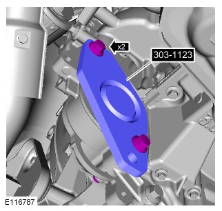

-
- Install the special tool.
-
Special Tool(s): 303-D121
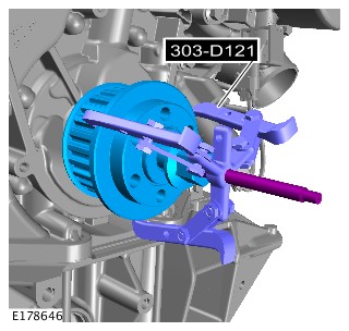
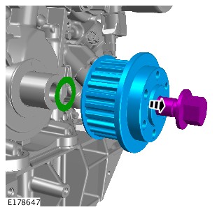
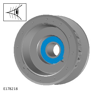
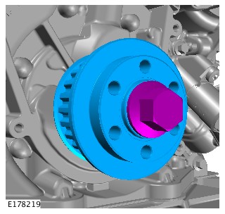

-
- Remove the special tool.
-
Special Tool(s): 303-1123
-
- Remove the special tool.
-
Special Tool(s): 303-1117
-
Install the timing belt.CAUTION:
If a new crankshaft pulley has been installed, renew the crankshaft mass damper retaining bolts.
Refer to:Timing Belt (303-01A Engine - TDV6 3.0L Diesel /TDV6 3.0L Diesel - Gen 1.5/TDV6 3.0L Diesel - Gen 2, Removal and Installation).
- Connect the startup battery ground cable.
Refer to:Specifications (414-00 Battery and Charging System - General Information, Specifications).
CRANKSHAFT REAR SEAL (G1509141)
- 12.21.20
- CRANKSHAFT REAR OIL SEAL - RENEW
- 3000 CC, TDV6, DIESEL, WITH PARTICULATE FILTER, WITH DIESEL EXHAUST FLUID, IC
- 6.50
- USED WITHINS
PART(S)
| STEP | PART NAME | QUANTITY |
|---|---|---|
| Installation Step 1 | Crankshaft rear seal | 1 |
-
Removal steps in this procedure may contain installation details.
-
Some variation in the illustrations may occur, but the essential information is always correct.
- Disconnect the battery ground cable.
Refer to:Specifications (414-00 Battery and Charging System - General Information, Specifications).
-
Raise and support the vehicle.WARNING:
Make sure to support the vehicle with axle stands.
-
Refer to:Crankshaft Position Sensor Ring (303-14A Electronic Engine Controls - TDV6 3.0L Diesel /TDV6 3.0L Diesel - Gen 1.5/TDV6 3.0L Diesel - Gen 2, Removal and Installation).

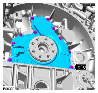
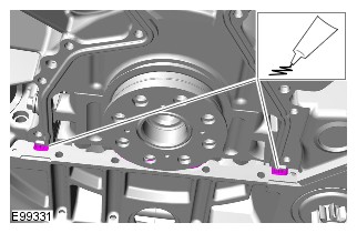
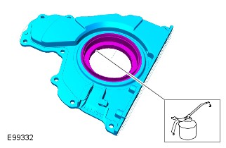
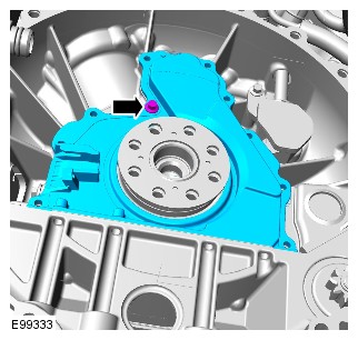
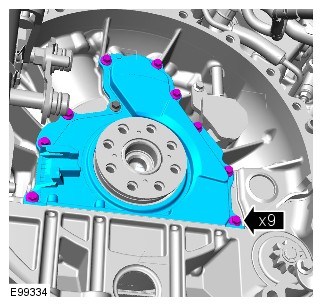
-
Refer to:Crankshaft Position Sensor Ring (303-14A Electronic Engine Controls - TDV6 3.0L Diesel /TDV6 3.0L Diesel - Gen 1.5/TDV6 3.0L Diesel - Gen 2, Removal and Installation).
- Connect the battery ground cable
Refer to:Specifications (414-00 Battery and Charging System - General Information, Specifications).
LEFT CYLINDER HEAD (G1509142)
- 12.29.04
- CYLINDER HEAD - ASSEMBLY - LEFT/ONE ONLY - RENEW
- 3000 CC, TDV6, DIESEL, WITH PARTICULATE FILTER, WITH DIESEL EXHAUST FLUID, IC
- 14.50
- USED WITHINS
PART(S)
| STEP | PART NAME | QUANTITY |
|---|---|---|
| Installation Step 2 | Cylinder head gasket | 1 |
| Installation Step 2 | Cylinder head bolts | 1 |
| Installation Step 6 | Water outlet connection O-ring seals | 1 |
-
Refer to:Specifications (414-00 Battery and Charging System - General Information, Specifications).
-
Raise and support the vehicle.WARNING:
Make sure to support the vehicle with axle stands.
-
Refer to:Left Camshaft (303-01A Engine - TDV6 3.0L Diesel /TDV6 3.0L Diesel - Gen 1.5/TDV6 3.0L Diesel - Gen 2, Removal and Installation).
-
Refer to:Glow Plugs (303-07C Glow Plug System - TDV6 3.0L Diesel /TDV6 3.0L Diesel - Gen 1.5/TDV6 3.0L Diesel - Gen 2, Removal and Installation).
-
Refer to:Left Exhaust Manifold (303-01A Engine - TDV6 3.0L Diesel /TDV6 3.0L Diesel - Gen 1.5/TDV6 3.0L Diesel - Gen 2, Removal and Installation).
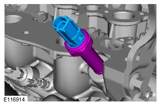
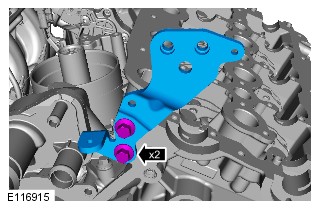
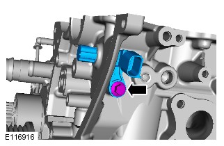
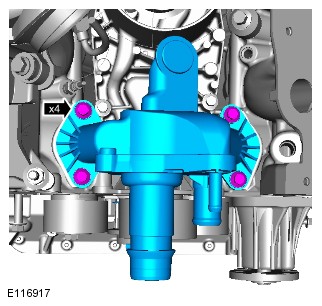
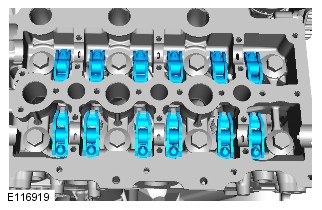
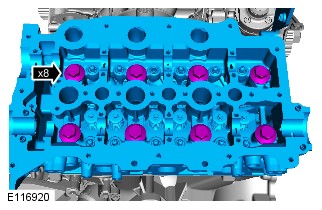
-
CAUTIONS:
-
Make sure that the mating faces are clean and free of foreign material.
-
An acceptable flatness of the cylinder head is 0.2mm.
- Clean and inspect the cylinder head and cylinder block.
- Check the cylinder head face for distortion, across the center and from corner to corner.
Refer to:Cylinder Head Distortion (303-00 Engine System - General Information, General Procedures).Refer to:Cylinder Head Gasket Selection - TDV6 3.0L Diesel (303-00 Engine System - General Information, General Procedures).
-
RIGHT CYLINDER HEAD (G1715989)
- 12.29.05
- CYLINDER HEAD - ASSEMBLY - RIGHT - RENEW
- 3000 CC, TDV6, DIESEL, WITH PARTICULATE FILTER, WITH DIESEL EXHAUST FLUID, IC
- 9.50
- USED WITHINS
PART(S)
| STEP | PART NAME | QUANTITY |
|---|---|---|
| Installation Step 2 | Cylinder head gasket | 1 |
| Installation Step 2 | Cylinder head bolts | 1 |
| Installation Step 11 | Exhaust manifold gasket | 1 |
| Installation Step 13 | Exhaust manifold cross-over pipe studs | 1 |
| Installation Step 14 | Exhaust manifold cross-over pipe nuts | 1 |
-
Removal steps in this procedure may contain installation details.
-
Some variation in the illustrations may occur, but the essential information is always correct.
- Disconnect the battery ground cable
Refer to:Specifications (414-00 Battery and Charging System - General Information, Specifications).
-
Raise and support the vehicle.WARNING:
Make sure to support the vehicle with axle stands.
-
Refer to:Right Turbocharger (303-04B Fuel Charging and Controls - Turbocharger - TDV6 3.0L Diesel, Removal and Installation).
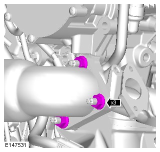
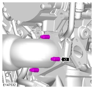
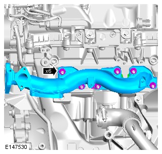
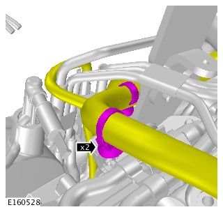
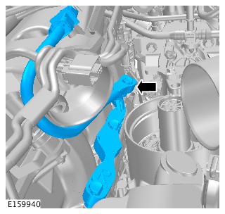
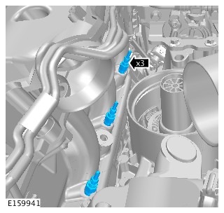
-
Refer to:Right Camshaft (303-01A Engine - TDV6 3.0L Diesel /TDV6 3.0L Diesel - Gen 1.5/TDV6 3.0L Diesel - Gen 2, Removal and Installation).
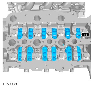
-
CAUTIONS:
-
Make sure that the mating faces are clean and free of foreign material.
-
An acceptable flatness of the cylinder head is 0.2mm.
- Clean and inspect the cylinder head and cylinder block.
- Check the cylinder head face for distortion, across the center and from corner to corner.
Refer to:Cylinder Head Distortion (303-00 Engine System - General Information, General Procedures).Refer to:Cylinder Head Gasket Selection - INGENIUM I4 2.0L Diesel (303-00 Engine System - General Information, General Procedures).
-
-
CAUTIONS:
-
Only tighten the bolts finger-tight at this stage.
-
Make sure that new bolts are installed.
-
Use care when installing the cylinder head. Damage to the cylinder block, cylinder head or cylinder head gasket may result.
-
The head gasket must be installed over the cylinder block dowels.
NOTES:-
Install a new gasket.
-
No additional lubrication to the cylinder head bolts is required.
-
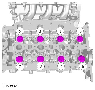
-
Refer to:Right Camshaft (303-01A Engine - TDV6 3.0L Diesel /TDV6 3.0L Diesel - Gen 1.5/TDV6 3.0L Diesel - Gen 2, Removal and Installation).

-
Refer to:Right Turbocharger (303-04B Fuel Charging and Controls - Turbocharger - TDV6 3.0L Diesel, Removal and Installation).
- Connect the battery ground cable
Refer to:Specifications (414-00 Battery and Charging System - General Information, Specifications).
-
CAUTIONS:
-
Only tighten the bolts finger-tight at this stage.
-
Make sure that new bolts are installed.
-
Use care when installing the cylinder head. Damage to the cylinder block, cylinder head or cylinder head gasket may result.
-
The head gasket must be installed over the cylinder block dowels.
NOTES:-
Install a new gasket.
-
No additional lubrication to the cylinder head bolts is required.
-
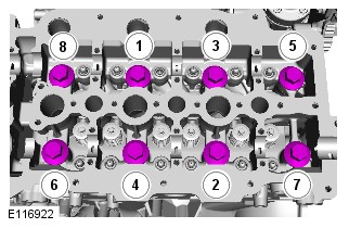
-
Refer to:Left Exhaust Manifold (303-01A Engine - TDV6 3.0L Diesel /TDV6 3.0L Diesel - Gen 1.5/TDV6 3.0L Diesel - Gen 2, Removal and Installation).
-
Refer to:Glow Plugs (303-07C Glow Plug System - TDV6 3.0L Diesel /TDV6 3.0L Diesel - Gen 1.5/TDV6 3.0L Diesel - Gen 2, Removal and Installation).
-
Refer to:Left Camshaft (303-01A Engine - TDV6 3.0L Diesel /TDV6 3.0L Diesel - Gen 1.5/TDV6 3.0L Diesel - Gen 2, Removal and Installation).
-
Refer to:Specifications (414-00 Battery and Charging System - General Information, Specifications).
RIGHT CYLINDER HEAD (G1957713)
- 12.29.05
- CYLINDER HEAD - ASSEMBLY - RIGHT - RENEW
- 3000 CC, TDV6, DIESEL, WITH PARTICULATE FILTER, WITH DIESEL EXHAUST FLUID, IC
- 9.50
- USED WITHINS
PART(S)
| STEP | PART NAME | QUANTITY |
|---|---|---|
| Installation Step 2 | Cylinder head bolts | 1 |
| Installation Step 2 | Cylinder head gasket | 1 |
-
Some variation in the illustrations may occur, but the essential information is always correct.
-
Some components shown removed for clarity.
-
Removal steps in this procedure may contain installation details.
- Disconnect the battery ground cable
Refer to:Specifications (414-00 Battery and Charging System - General Information, Specifications).
-
Raise and support the vehicle.WARNING:
Make sure to support the vehicle with axle stands.
-
Refer to:Right Exhaust Manifold (303-01A Engine - TDV6 3.0L Diesel /TDV6 3.0L Diesel - Gen 1.5/TDV6 3.0L Diesel - Gen 2, Removal and Installation).
-
Refer to:Right Camshaft (303-01A Engine - TDV6 3.0L Diesel /TDV6 3.0L Diesel - Gen 1.5/TDV6 3.0L Diesel - Gen 2, Removal and Installation).
-
CAUTIONS:
-
Make sure that the mating faces are clean and free of foreign material.
-
An acceptable flatness of the cylinder head is 0.2mm.
- Clean and inspect the cylinder head and cylinder block.
- Check the cylinder head face for distortion, across the center and from corner to corner.
Refer to:Cylinder Head Distortion (303-00 Engine System - General Information, General Procedures).Refer to:Cylinder Head Gasket Selection - TDV6 3.0L Diesel (303-00 Engine System - General Information, General Procedures).
-
-
CAUTIONS:
-
Only tighten the bolts finger-tight at this stage.
-
Make sure that new bolts are installed.
-
Use care when installing the cylinder head. Damage to the cylinder block, cylinder head or cylinder head gasket may result.
-
The head gasket must be installed over the cylinder block dowels.
NOTES:-
Install a new gasket.
-
No additional lubrication to the cylinder head bolts is required.
-
-
Refer to:Right Camshaft (303-01A Engine - TDV6 3.0L Diesel /TDV6 3.0L Diesel - Gen 1.5/TDV6 3.0L Diesel - Gen 2, Removal and Installation).
-
Refer to:Right Exhaust Manifold (303-01A Engine - TDV6 3.0L Diesel /TDV6 3.0L Diesel - Gen 1.5/TDV6 3.0L Diesel - Gen 2, Removal and Installation).
- Connect the battery ground cable
Refer to:Specifications (414-00 Battery and Charging System - General Information, Specifications).
-
Refer to:High-Pressure Fuel System Bleeding (310-00 Fuel System - General Information, General Procedures).
LEFT ENGINE MOUNT (G1509143)
- 12.45.11
- MOUNTING - LH - RENEW
- RIGHT HAND DRIVE, 3000 CC, TDV6, DIESEL, IC
- 3.20
- USED WITHINS
- Removal steps in this procedure may contain installation details.
- Some variation in the illustrations may occur, but the essential information is always correct.
- Disconnect the startup battery ground cable.
Refer to:Specifications (414-00 Battery and Charging System - General Information, Specifications).
- Remove the air conditioning (A/C) compressor.
Refer to:Air Conditioning Compressor - TDV6 3.0L Diesel /TDV6 3.0L Diesel - Gen 1.5/TDV6 3.0L Diesel - Gen 2 (412-01 Climate Control, Removal and Installation).
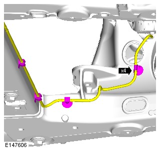
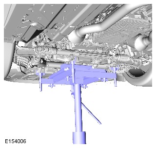
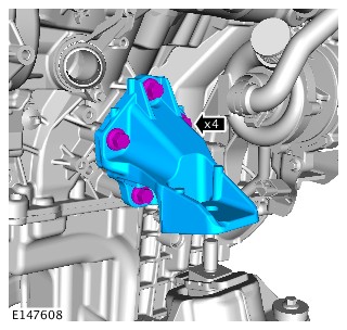
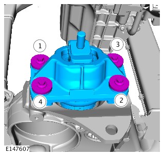
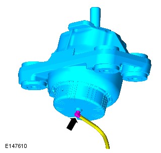
-
Raise and support the vehicle.WARNING:
Do not work on or under a vehicle supported only by a jack. Always support the vehicle on safety stands.
- Install the air conditioning (A/C) compressor.
Refer to:Air Conditioning Compressor - TDV6 3.0L Diesel /TDV6 3.0L Diesel - Gen 1.5/TDV6 3.0L Diesel - Gen 2 (412-01 Climate Control, Removal and Installation).Refer to:Air Conditioning Compressor - TDV6 3.0L Diesel /TDV6 3.0L Diesel - Gen 1.5/TDV6 3.0L Diesel - Gen 2 (412-01 Climate Control, Removal and Installation).
- Connect the startup battery ground cable.
Refer to:Specifications (414-00 Battery and Charging System - General Information, Specifications).
RIGHT ENGINE MOUNT (G1509144)
- 12.45.12
- MOUNTING - RH - RENEW
- RIGHT HAND DRIVE, 3000 CC, TDV6, DIESEL, IC
- 1.30
- USED WITHINS
PART(S)
| STEP | PART NAME | QUANTITY |
|---|---|---|
| Installation Step 10 | Steering column lower shaft lower bolt | 1 |
Removal steps in this procedure may contain installation details.
- Remove the startup battery ground cable.
Refer to:Specifications (414-00 Battery and Charging System - General Information, Specifications).
- Remove the generator.
Refer to:Generator (414-02A Generator and Regulator - TDV6 3.0L Diesel /TDV6 3.0L Diesel - Gen 1.5/TDV6 3.0L Diesel - Gen 2, Removal and Installation).
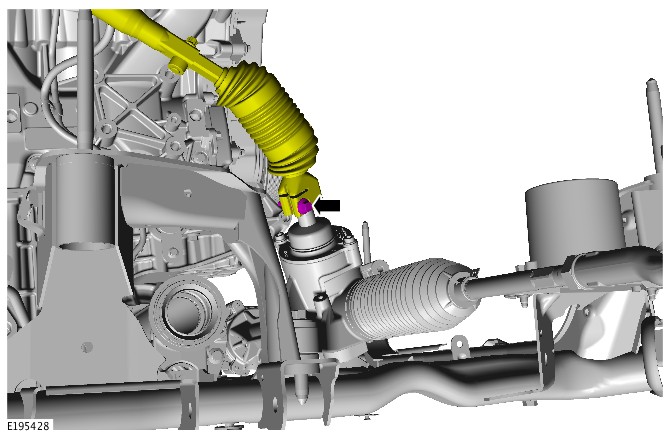
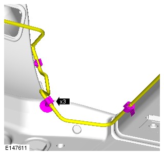
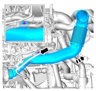
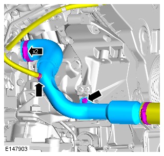
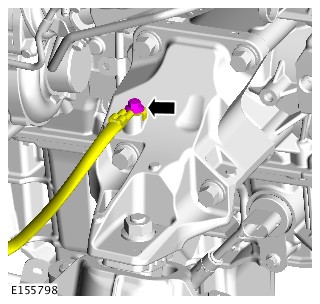
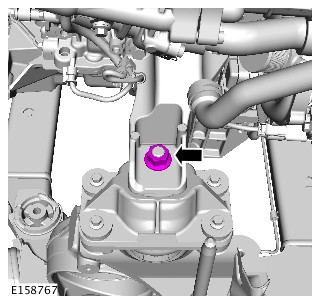
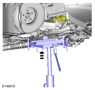
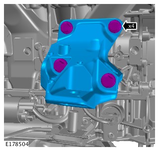
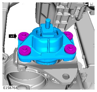
- Lower the engine onto the engine mounting.
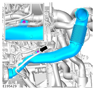
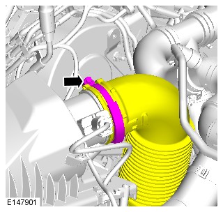
- Install the generator.
Refer to:Generator (414-02A Generator and Regulator - TDV6 3.0L Diesel /TDV6 3.0L Diesel - Gen 1.5/TDV6 3.0L Diesel - Gen 2, Removal and Installation).
- Connect the startup battery ground cable.
Refer to:Specifications (414-00 Battery and Charging System - General Information, Specifications).
LEFT EXHAUST MANIFOLD (G1509145)
- 30.15.10
- EXHAUST MANIFOLD - RENEW
- 3000 CC, TDV6, DIESEL, WITH PARTICULATE FILTER, WITH DIESEL EXHAUST FLUID, IC
- 5.40
- USED WITHINS
PART(S)
| STEP | PART NAME | QUANTITY |
|---|---|---|
| Installation Step 1 | Exhaust manifold gasket | 1 |
| Installation Step 1 | Exhaust manifold nuts | 6 |
| Installation Step 3 | Exhaust manifold cross-over pipe studs | 3 |
| Installation Step 4 | Exhaust manifold cross-over pipe nuts | 3 |
| Installation Step 17 | Turbocharger oil return pipe seals | 1 |
| Installation Step 18 | Turbocharger oil return pipe seals | 1 |
Some variation in the illustrations may occur, but the essential information is always correct.
- Remove the left exhaust gas temperature sensor.
Refer to:Left Exhaust Gas Temperature Sensor (303-14A Electronic Engine Controls - TDV6 3.0L Diesel /TDV6 3.0L Diesel - Gen 1.5/TDV6 3.0L Diesel - Gen 2, Removal and Installation).
- Remove the left turbocharger.
Refer to:Left Turbocharger - TDV6 3.0L Diesel /TDV6 3.0L Diesel - Gen 1.5 (303-04B Fuel Charging and Controls - Turbocharger - TDV6 3.0L Diesel, Removal and Installation).
- Remove the left exhaust gas recirculation valve.
Refer to:Left Exhaust Gas Recirculation Valve - TDV6 3.0L Diesel - Gen 2 (303-08A Engine Emission Control - TDV6 3.0L Diesel /TDV6 3.0L Diesel - Gen 1.5/TDV6 3.0L Diesel - Gen 2, Removal and Installation).
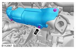
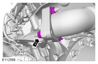
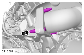
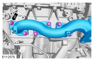
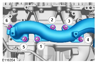


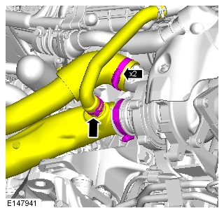


- Install the left exhaust gas recirculation valve.
Refer to:Left Exhaust Gas Recirculation Valve - TDV6 3.0L Diesel - Gen 2 (303-08A Engine Emission Control - TDV6 3.0L Diesel /TDV6 3.0L Diesel - Gen 1.5/TDV6 3.0L Diesel - Gen 2, Removal and Installation).
- Install the left exhaust gas temperature sensor.
Refer to:Left Exhaust Gas Temperature Sensor (303-14A Electronic Engine Controls - TDV6 3.0L Diesel /TDV6 3.0L Diesel - Gen 1.5/TDV6 3.0L Diesel - Gen 2, Removal and Installation).
RIGHT EXHAUST MANIFOLD (G1509146)
- 30.15.11
- MANIFOLD - EXHAUST - RH/REAR - RENEW
- 3000 CC, TDV6, DIESEL, WITH PARTICULATE FILTER, WITH DIESEL EXHAUST FLUID, IC
- 3.50
- USED WITHINS
PART(S)
| STEP | PART NAME | QUANTITY |
|---|---|---|
| Installation Step 1 | Exhaust manifold gasket | 1 |
| Installation Step 1 | Exhaust manifold nuts | 6 |
| Installation Step 3 | Exhaust manifold cross-over pipe gaskets | 1 |
| Installation Step 3 | Exhaust manifold cross-over pipe studs | 1 |
| Installation Step 4 | Exhaust manifold cross-over pipe nuts | 1 |
| Installation Step 11 | Turbocharger oil feed pipe banjo bolt washers | 1 |
| Installation Step 16 | Turbocharger oil return pipe seals | 1 |
| Installation Step 17 | Turbocharger oil return pipe seals | 1 |
-
Refer to:Right Turbocharger (303-04B Fuel Charging and Controls - Turbocharger - TDV6 3.0L Diesel, Removal and Installation).
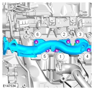


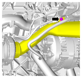


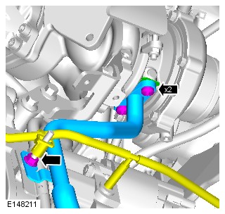

-
Refer to:Right Exhaust Gas Recirculation Valve (303-08A Engine Emission Control - TDV6 3.0L Diesel /TDV6 3.0L Diesel - Gen 1.5/TDV6 3.0L Diesel - Gen 2, Removal and Installation).
-
Refer to:Engine Oil Vacuum Draining and Filling (303-01A Engine - TDV6 3.0L Diesel /TDV6 3.0L Diesel - Gen 1.5/TDV6 3.0L Diesel - Gen 2, General Procedures).
RIGHT EXHAUST MANIFOLD (G1957714)
- 30.15.11
- MANIFOLD - EXHAUST - RH/REAR - RENEW
- 3000 CC, TDV6, DIESEL, WITH PARTICULATE FILTER, WITH DIESEL EXHAUST FLUID, IC
- 3.50
- USED WITHINS
PART(S)
| STEP | PART NAME | QUANTITY |
|---|---|---|
| Removal Step 6 | Exhaust manifold cross-over pipe nuts | 1 |
| Removal Step 7 | Crossover pipe gasket | 1 |
| Removal Step 7 | Exhaust manifold cross-over pipe studs | 1 |
| Removal Step 8 | Exhaust manifold gasket | 1 |
| Removal Step 8 | Exhaust manifold nuts | 1 |
-
Some variation in the illustrations may occur, but the essential information is always correct.
-
Some components shown removed for clarity.
-
Removal steps in this procedure may contain installation details.
-
Refer to:Specifications (414-01 Battery, Mounting and Cables, Specifications).
-
Raise and support the vehicle.CAUTION:
Do not work on or under a vehicle supported only by a jack. Always support the vehicle on safety stands.
-
Refer to:Exhaust System - Vehicles Without: Diesel Particulate Filter (DPF) (309-00A Exhaust System - TDV6 3.0L Diesel - Gen 2, Removal and Installation).
-
Refer to:Right Exhaust Gas Recirculation Valve (303-08A Engine Emission Control - TDV6 3.0L Diesel /TDV6 3.0L Diesel - Gen 1.5/TDV6 3.0L Diesel - Gen 2, Removal and Installation).

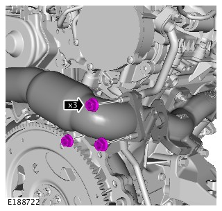
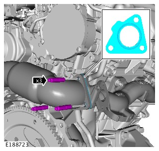


- To install, reverse the removal procedure.
EXHAUST MANIFOLD CROSS-OVER PIPE (G1509147)
- 30.15.29
- PIPE - CROSS-OVER - EXHAUST MANIFOLD - RENEW
- 3000 CC, TDV6, WITH PARTICULATE FILTER, WITH DIESEL EXHAUST FLUID
- 3.40
- USED WITHINS
GENERAL EQUIPMENT
| EQUIPMENT NAME |
|---|
| Transmission jack |
PART(S)
| STEP | PART NAME | QUANTITY |
|---|---|---|
| Installation Step 1 | Exhaust manifold cross-over pipe gaskets | 1 |
| Installation Step 2 | Exhaust manifold cross-over pipe studs | 1 |
| Installation Step 3 | Exhaust manifold studs | 1 |
| Installation Step 5 | Exhaust manifold cross-over pipe nuts and bolts | 1 |
Take care when handling the cross-over pipe as damage to the insulating material may occur.
Some variation in the illustrations may occur, but the essential information is always correct.
-
Raise and support the vehicle.WARNING:
Make sure to support the vehicle with axle stands.
-
Refer to:Exhaust System (309-00B Exhaust System - V6 S/C 3.0L Petrol, Removal and Installation).Refer to:Exhaust System - Vehicles Without: Diesel Particulate Filter (DPF) (309-00A Exhaust System - TDV6 3.0L Diesel - Gen 2, Removal and Installation).
-
Refer to:Transmission Support Crossmember - TDV6 3.0L Diesel /TDV6 3.0L Diesel - Gen 1.5/TDV6 3.0L Diesel - Gen 2 (502-02 Full Frame and Body Mounting, Removal and Installation).


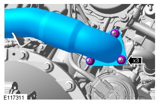
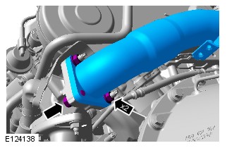
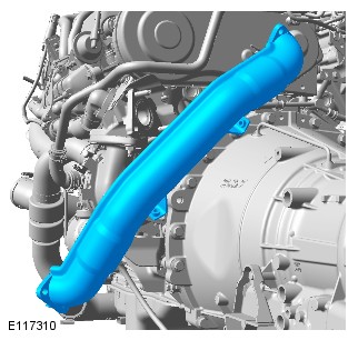
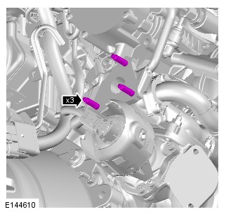
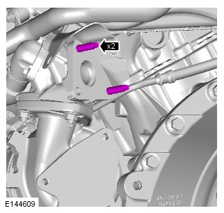
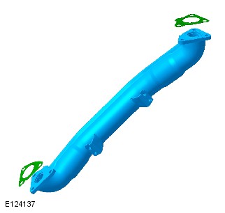


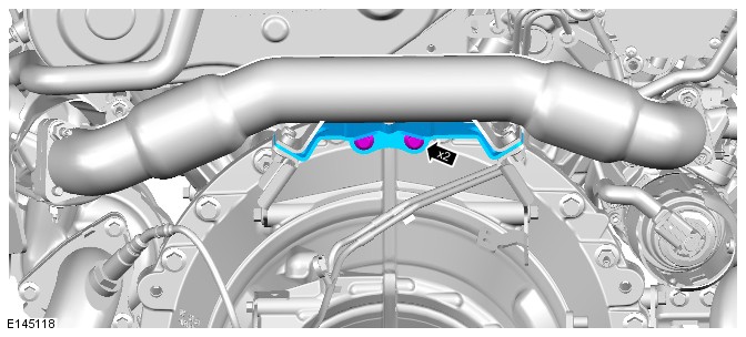
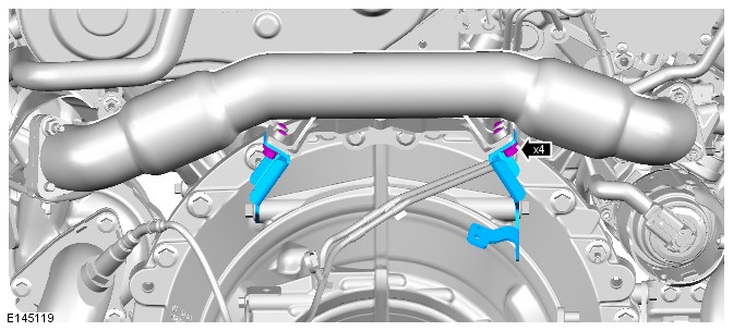

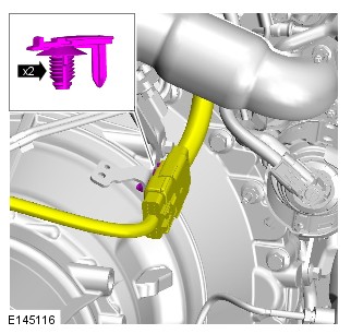
-
General Equipment: Transmission jack
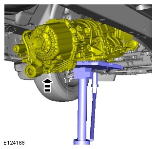
-
Refer to:Transmission Support Crossmember - TDV6 3.0L Diesel /TDV6 3.0L Diesel - Gen 1.5/TDV6 3.0L Diesel - Gen 2 (502-02 Full Frame and Body Mounting, Removal and Installation).
-
Refer to:Exhaust System (309-00B Exhaust System - V6 S/C 3.0L Petrol, Removal and Installation).Refer to:Exhaust System - Vehicles Without: Diesel Particulate Filter (DPF) (309-00A Exhaust System - TDV6 3.0L Diesel - Gen 2, Removal and Installation).
FLEXPLATE (G1509148)
- 12.53.13
- DRIVE PLATE - AUTOMATIC - RENEW
- 3000 CC, TDV6, DIESEL, WITH PARTICULATE FILTER, WITH DIESEL EXHAUST FLUID, IC
- 6.10
- USED WITHINS
SPECIAL TOOL(S)
303-1123
Locking Tool, Flywheel
PART(S)
| STEP | PART NAME | QUANTITY |
|---|---|---|
| Installation Step 1 | Flexplate bolts | 8 |
Some variation in the illustrations may occur, but the essential information is always correct.
- Disconnect the battery ground cable.
Refer to:Specifications (414-00 Battery and Charging System - General Information, Specifications).
-
Raise and support the vehicle.WARNING:
Make sure to support the vehicle with axle stands.
-
Refer to:Starter Motor (303-06A Starting System - TDV6 3.0L Diesel /TDV6 3.0L Diesel - Gen 1.5/TDV6 3.0L Diesel - Gen 2, Removal and Installation).
-
Refer to:Transmission - TDV6 3.0L Diesel /TDV6 3.0L Diesel - Gen 1.5/TDV6 3.0L Diesel - Gen 2, Vehicles With: Twin Speed Transfer Case (307-01A Automatic Transmission/Transaxle - Vehicles With: 8HP70 8-Speed Automatic Transmission AWD, Removal).
-
- Install the special tool.
-
Special Tool(s): 303-1123
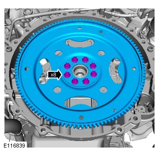

-
- Remove the special tool.
-
Special Tool(s): 303-1123
-
Refer to:Transmission - TDV6 3.0L Diesel /TDV6 3.0L Diesel - Gen 1.5/TDV6 3.0L Diesel - Gen 2, Vehicles With: Twin Speed Transfer Case (307-01A Automatic Transmission/Transaxle - Vehicles With: 8HP70 8-Speed Automatic Transmission AWD, Installation).
-
Refer to:Starter Motor (303-06A Starting System - TDV6 3.0L Diesel /TDV6 3.0L Diesel - Gen 1.5/TDV6 3.0L Diesel - Gen 2, Removal and Installation).
- Connect the battery ground cable.
Refer to:Specifications (414-00 Battery and Charging System - General Information, Specifications).
OIL FILTER ELEMENT (G1509150)
- 12.60.02
- OIL FILTER ELEMENT - RENEW
- 3000 CC, TDV6
- 0.10
- USED WITHINS
PART(S)
| STEP | PART NAME | QUANTITY |
|---|---|---|
| Installation Step 2 | Oil filter and O-ring seal kit | 1 |
Make sure that the correct tools are used to remove and install the oil filter element cap.
Some variation in the illustrations may occur, but the essential information is always correct.
-
Refer to:Engine Cover - TDV6 3.0L Diesel /TDV6 3.0L Diesel - Gen 1.5/TDV6 3.0L Diesel - Gen 2 (501-05 Interior Trim and Ornamentation, Removal and Installation).
-
Refer to:Engine Cover - TDV6 3.0L Diesel /TDV6 3.0L Diesel - Gen 1.5/TDV6 3.0L Diesel - Gen 2 (501-05 Interior Trim and Ornamentation, Removal and Installation).
- Start and run the engine.
- Check and top-up the engine oil.
OIL PAN (G1671685)
- 12.60.44
- OIL PAN - RENEW
- 3000 CC, TDV6, DIESEL, WITH PARTICULATE FILTER, WITH DIESEL EXHAUST FLUID, IC
- 5.90
- USED WITHINS
PART(S)
| STEP | PART NAME | QUANTITY |
|---|---|---|
| Removal Step 6 | Turbocharger oil return pipe gasket(s) | 1 |
| Removal Step 7 | Turbocharger oil return pipe gasket(s) | 1 |
| Removal Step 11 | Turbocharger oil return pipe gasket(s) | 1 |
| Removal Step 13 | Oil pan gasket | 1 |
| Removal Step 16 | Oil level gauge O-ring seal | 1 |
| Removal Step 17 | Oil pick up pipe | 1 |
| Removal Step 18 | Vent tube | 1 |
-
Removal steps in this procedure may contain installation details.
-
Some variation in the illustrations may occur, but the essential information is always correct.
- Disconnect the battery ground cable.
Refer to:Specifications (414-00 Battery and Charging System - General Information, Specifications).
-
Refer to:Engine Oil Draining and Filling (303-01A Engine - TDV6 3.0L Diesel /TDV6 3.0L Diesel - Gen 1.5/TDV6 3.0L Diesel - Gen 2, General Procedures).
-
Refer to:Starter Motor (303-06A Starting System - TDV6 3.0L Diesel /TDV6 3.0L Diesel - Gen 1.5/TDV6 3.0L Diesel - Gen 2, Removal and Installation).
-
Refer to:Differential (205-03 Front Drive Axle/Differential, Removal and Installation).
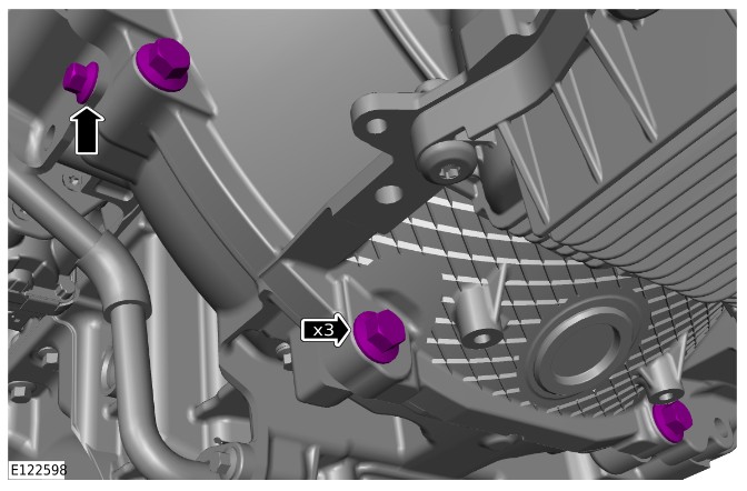


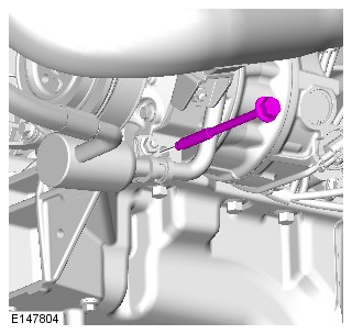
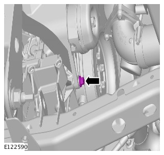
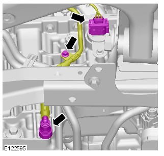


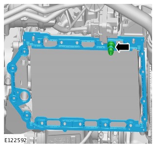


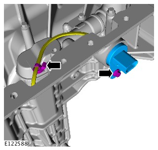

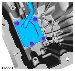
-
CAUTIONS:
-
Installation of the oil pan and tightening must be completed within 7 minutes of applying the sealant.
-
Make sure that the mating faces are clean and free of corrosion and foreign material.
NOTE:Right-hand shown, left-hand similar.
Apply sealant WSE-M4G323-A5 in an 8mm bead to the cylinder block in the area illustrated. -

- To install, reverse the removal procedure.
ELECTRIC OIL PUMP - TDV6 3.0L DIESEL - GEN 2 (G1875418)
- 12.60.26
- OIL PUMP - RENEW
- 3000 CC, TDV6, DIESEL, GEN 2, IC
- 4.00
- USED WITHINS
SPECIAL TOOL(S)
303-1121A
Installer, Crankshaft Seal
303-1122
Installer, Crankshaft Front Seal
PART(S)
| STEP | PART NAME | QUANTITY |
|---|---|---|
| Installation Step 11 | Crankshaft front oil seal | 1 |
| Installation Step 17 | Crankshaft pulley bolt | 1 |
- Disconnect the battery ground cable.
Refer to:Specifications (414-00 Battery and Charging System - General Information, Specifications).
- Remove the generator.
Refer to:Generator (414-02A Generator and Regulator - TDV6 3.0L Diesel /TDV6 3.0L Diesel - Gen 1.5/TDV6 3.0L Diesel - Gen 2, Removal and Installation).
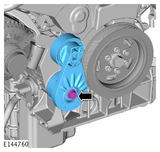

-
Refer to:Timing Belt (303-01A Engine - TDV6 3.0L Diesel /TDV6 3.0L Diesel - Gen 1.5/TDV6 3.0L Diesel - Gen 2, Removal and Installation).
-
Refer to:Crankshaft Pulley - TDV6 3.0L Diesel - Gen 2 (303-01A Engine - TDV6 3.0L Diesel /TDV6 3.0L Diesel - Gen 1.5/TDV6 3.0L Diesel - Gen 2, Removal and Installation).
-
Raise and support the vehicle.WARNING:
Do not work on or under a vehicle supported only by a jack. Always support the vehicle on safety stands.
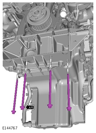
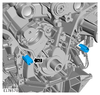
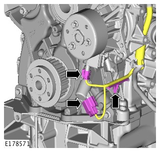

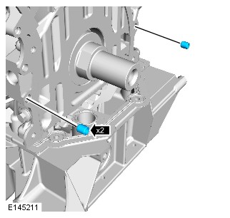
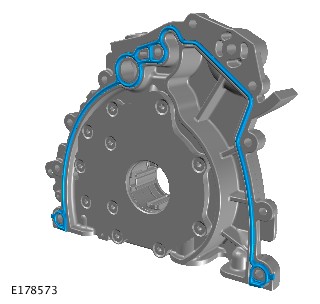
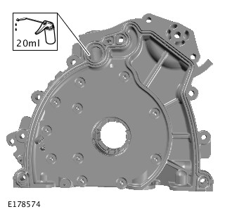
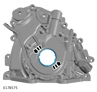
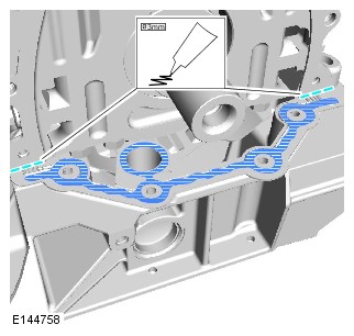
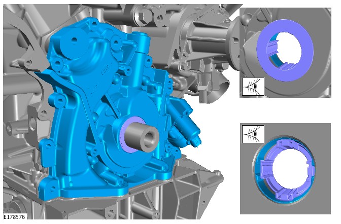


-
CAUTION:
Do not use any lubricant on the crankshaft front seal, special tools or the crankshaft. Failure to follow this instruction may result in damage to the vehicle.
NOTE:Make sure all component mating faces are clean.
Install a new crankshaft front seal to the special tool.Special Tool(s): 303-1122
-
NOTE:
Remove the sleeve from the special tool.
Reposition the crankshaft front seal along the special tool.Special Tool(s): 303-1122
-
Install the special tool to the crankshaft.Special Tool(s): 303-1122
-
Remove the special tool from the crankshaft.Special Tool(s): 303-1122
-
Install the special tool to the crankshaft.Special Tool(s): 303-1121A
-
NOTES:
-
Make sure the seal is installed correctly.
-
Use the crankshaft bolt with the service tool.
Install the special tool to the crankshaft.Special Tool(s): 303-1121A -
-
NOTES:
-
Make sure the seal is installed correctly.
-
Wait 10 seconds before removing the crankshaft seal installation tool.
Remove and discard the crankshaft pulley retaining bolt.Special Tool(s): 303-1121A -
-
Refer to:Crankshaft Pulley - TDV6 3.0L Diesel - Gen 2 (303-01A Engine - TDV6 3.0L Diesel /TDV6 3.0L Diesel - Gen 1.5/TDV6 3.0L Diesel - Gen 2, Removal and Installation).
-
Refer to:Timing Belt (303-01A Engine - TDV6 3.0L Diesel /TDV6 3.0L Diesel - Gen 1.5/TDV6 3.0L Diesel - Gen 2, Removal and Installation).

- Install the generator.
Refer to:Generator (414-02A Generator and Regulator - TDV6 3.0L Diesel /TDV6 3.0L Diesel - Gen 1.5/TDV6 3.0L Diesel - Gen 2, Removal and Installation).
- Connect the battery ground cable.
Refer to:Specifications (414-00 Battery and Charging System - General Information, Specifications).
TIMING BELT (G1509153)
- 12.65.18
- TIMING BELT - CAMSHAFT - RENEW
- 3000 CC, TDV6
- 2.50
- USED WITHINS
SPECIAL TOOL(S)
303-1117
Timing Peg, Automatic Transmission
303-1126
Timing Peg, Camshaft Pulley
PART(S)
| STEP | PART NAME | QUANTITY |
|---|---|---|
| Installation Step 2 | Timing belt and tensioner kit | 1 |
-
Refer to:Timing Cover (303-01A Engine - TDV6 3.0L Diesel /TDV6 3.0L Diesel - Gen 1.5/TDV6 3.0L Diesel - Gen 2, Removal and Installation).Refer to:Timing Cover (303-01A Engine - TDV6 3.0L Diesel /TDV6 3.0L Diesel - Gen 1.5/TDV6 3.0L Diesel - Gen 2, Removal and Installation).
-
Refer to:Starter Motor (303-06A Starting System - TDV6 3.0L Diesel /TDV6 3.0L Diesel - Gen 1.5/TDV6 3.0L Diesel - Gen 2, Removal and Installation).
- Rotate the crankshaft clockwise to align the crankshaft alignment hole in the flywheel or flexplate with the block aperture.
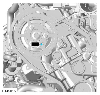
-
Special Tool(s): 303-1117
-
Special Tool(s): 303-1126
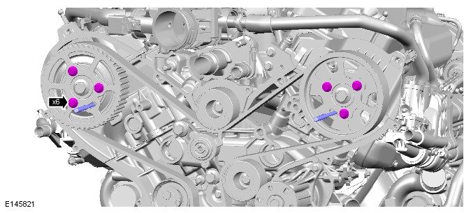
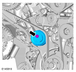


-
CAUTION:
Make sure the camshaft pulleys remain in the clockwise position.
- Install the new timing belt.
- Starting at the crankshaft pulley, install the timing belt in a counter-clockwise direction, in the sequence shown.
- Stage one: Attach the timing belt to the crankshaft pulley.
- Stage two: Attach the timing belt to the idler pulley.
- Stage three: Attach the timing belt to the left-hand camshaft pulley.
- Stage four: Attach the timing belt to the idler pulley.
- Stage five: Attach the timing belt to the RH camshaft pulley.
- Stage six: Attach the timing belt to the timing belt tensioner.


-
Special Tool(s): 303-1126
-
Special Tool(s): 303-1117
-
Rotate the engine two complete turns clockwise.CAUTION:
Only rotate the crankshaft clockwise.
-
Special Tool(s): 303-1117
-
Special Tool(s): 303-1117
-
Refer to:Starter Motor (303-06A Starting System - TDV6 3.0L Diesel /TDV6 3.0L Diesel - Gen 1.5/TDV6 3.0L Diesel - Gen 2, Removal and Installation).
-
Refer to:Timing Cover (303-01A Engine - TDV6 3.0L Diesel /TDV6 3.0L Diesel - Gen 1.5/TDV6 3.0L Diesel - Gen 2, Removal and Installation).
TIMING COVER (G1875417)
- 12.65.03
- COVER - CAMSHAFT DRIVE BELT - RENEW
- 3000 CC, TDV6
- 1.60
- USED WITHINS
- 12.65.03
- COVER - CAMSHAFT DRIVE BELT - RENEW
- 3000 CC, TDV6, GEN 2
- 2.20
- USED WITHINS
PART(S)
| STEP | PART NAME | QUANTITY |
|---|---|---|
| Removal Step 13 | Engine coolant pump pulley bolts | 1 |
| Removal Step 15 | Timing belt cover gasket | 1 |
- Disconnect the battery ground cable.
Refer to:Specifications (414-00 Battery and Charging System - General Information, Specifications).
-
Refer to:Cooling System Partial Draining and Vacuum Filling (303-03F Engine Cooling - TDV8 4.4L Diesel, General Procedures).Refer to:Cooling System Partial Draining and Vacuum Filling (303-03A Engine Cooling - TDV6 3.0L Diesel /TDV6 3.0L Diesel - Gen 1.5/TDV6 3.0L Diesel - Gen 2, General Procedures).
-
Refer to:Engine Cover - TDV6 3.0L Diesel /TDV6 3.0L Diesel - Gen 1.5/TDV6 3.0L Diesel - Gen 2 (501-05 Interior Trim and Ornamentation, Removal and Installation).
-
Refer to:Accessory Drive Belt Pulley (303-05D Accessory Drive - TDV8 4.4L Diesel, Removal and Installation).Refer to:Accessory Drive Belt Pulley (303-05A Accessory Drive - TDV6 3.0L Diesel /TDV6 3.0L Diesel - Gen 1.5/TDV6 3.0L Diesel - Gen 2, Removal and Installation).


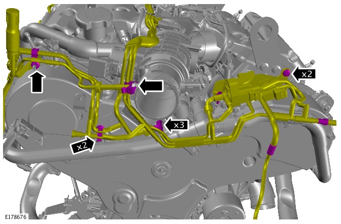


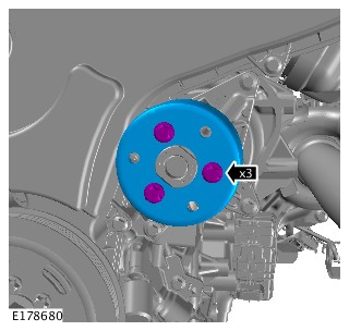

- To install, reverse the removal procedure.
LEFT VALVE COVER (G1509155)
- 12.29.43
- CAMSHAFT COVER - LEFT - RENEW
- 3000 CC, TDV6
- 4.40
- USED WITHINS
SPECIAL TOOL(S)
100-012
Slide Hammer
310-213
Fuel Injector Removal Adapter
PART(S)
| STEP | PART NAME | QUANTITY |
|---|---|---|
| Installation Step 2 | Camshaft cover gasket | 1 |
| Installation Step 11 | Fuel Injector replacement kits | 3 |
-
This procedure contains some variation in the illustrations depending on the vehicle specification, but the essential information is always correct.
-
This procedure contains illustrations showing certain components removed to provide extra clarity.
- Disconnect the startup battery ground cable.
Refer to:Specifications (414-00 Battery and Charging System - General Information, Specifications).
- Raise and support the vehicle on a suitable 2 post lift.
Refer to:Lifting (100-02 Jacking and Lifting, Description and Operation).
- Partially drain the cooling system.
Refer to:Cooling System Partial Draining and Vacuum Filling (303-03A Engine Cooling - TDV6 3.0L Diesel /TDV6 3.0L Diesel - Gen 1.5/TDV6 3.0L Diesel - Gen 2, General Procedures).
- Remove the throttle body.
Refer to:Intake Air Shutoff Throttle (303-04A Fuel Charging and Controls - TDV6 3.0L Diesel /TDV6 3.0L Diesel - Gen 1.5/TDV6 3.0L Diesel - Gen 2, Removal and Installation).
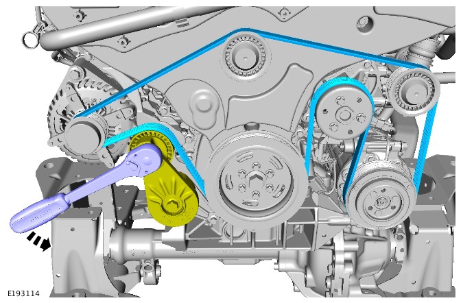
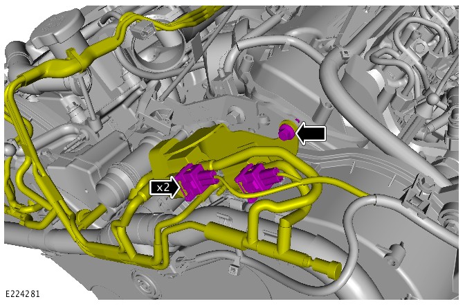

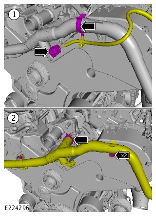
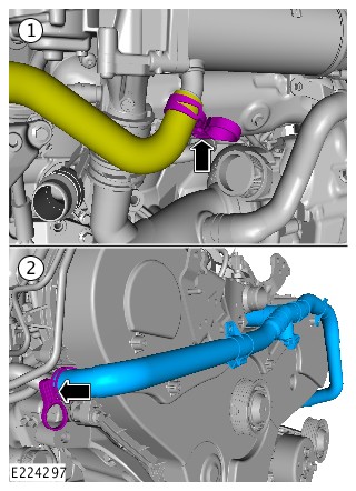
- Always follow the cleaning process before doing any repairs to the fuel injection system components. Failure to follow this instruction may result in damage to the fuel injection system.
Refer to:Fuel Injection Component Cleaning (303-04A Fuel Charging and Controls - TDV6 3.0L Diesel /TDV6 3.0L Diesel - Gen 1.5/TDV6 3.0L Diesel - Gen 2, General Procedures).
- Remove the left fuel rail.
Refer to:Left Fuel Rail (303-04A Fuel Charging and Controls - TDV6 3.0L Diesel /TDV6 3.0L Diesel - Gen 1.5/TDV6 3.0L Diesel - Gen 2, Removal and Installation).


- Repeat steps 14 to 16 for the remaining 2 fuel injectors.


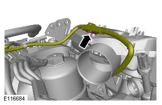


-
CAUTIONS:
-
Use only a plastic scraper when removing the sealing material.
-
Use lint free cloth.
-
Make sure that the mating faces are clean and free of corrosion and foreign material.
-
Installation of the valve cover and tightening must be carried out within 7 minutes of applying the sealant.
NOTES:-
(1) Right valve cover.
-
(2) Left valve cover.
Apply (0.35g) a small amount of gasket sealant (Loctite 5900 or Hylosil sealant) in each location as shown on the illustration. Install the valve cover immediately after applying the sealant. -
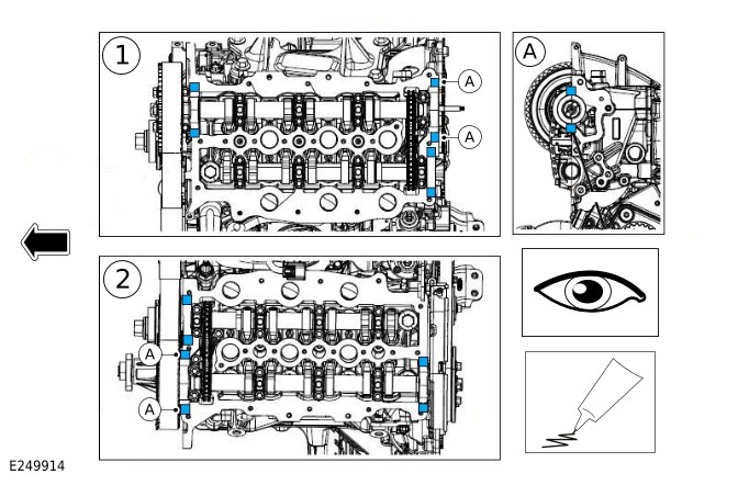
-
CAUTION:
Make sure that the mating faces are clean and free of corrosion and foreign material.
- Install a new left valve cover gasket
- Install, but do not fully tighten the 11 left valve cover bolts.
-
CAUTION:
Take care not to damage any surrounding components.
- Using a suitable trim tool, release the timing cover from the left valve cover.
- Install, but do not fully tighten the 2 left valve cover bolts.

-
- Install the 6 timing cover bolts.
Torque: 10Nm
- Install the 6 timing cover bolts.
- Install the coolant pipe to the left valve cover.
Torque: 8Nm
- Install the engine mounting bracket.
Torque: 8Nm
- Install the fuel rail mounting bracket.
Torque: 23Nm
- Install the left valve cover mounting bracket.
Torque: 10Nm
-
- Install the Noise, Vibration and Harshness material.
- Install the pins.
- Install the wiring harness and connect the electrical connectors.
-
- Install new fuel injector retaining clamps.
- Install new O-ring seals.
- Install new sealing washers.
- Install the fuel injectors.
Torque: 9Nm
- Connect the fuel injector wiring harness.
- Install the left fuel rail.
Refer to:Left Fuel Rail (303-04A Fuel Charging and Controls - TDV6 3.0L Diesel /TDV6 3.0L Diesel - Gen 1.5/TDV6 3.0L Diesel - Gen 2, Removal and Installation).
-
- Install the Exhaust Gas Recirculation (EGR) engine coolant crossover pipe.
Torque: 8Nm
- Connect the electrical connector.
- Install the Exhaust Gas Recirculation (EGR) engine coolant crossover pipe.
- Install the emergency park release assembly.
Torque: 8Nm
-
- Install the vacuum harness.
- Connect the electrical connectors.
- Install the accessory drive belt.
- Install the throttle body.
Refer to:Intake Air Shutoff Throttle (303-04A Fuel Charging and Controls - TDV6 3.0L Diesel /TDV6 3.0L Diesel - Gen 1.5/TDV6 3.0L Diesel - Gen 2, Removal and Installation).
- Fill the drain the cooling system.
Refer to:Cooling System Partial Draining and Vacuum Filling (303-03A Engine Cooling - TDV6 3.0L Diesel /TDV6 3.0L Diesel - Gen 1.5/TDV6 3.0L Diesel - Gen 2, General Procedures).
- Connect the startup battery ground cable.
Refer to:Specifications (414-00 Battery and Charging System - General Information, Specifications).
RIGHT VALVE COVER (G1509156)
- 12.29.44
- CAMSHAFT COVER - RIGHT - RENEW
- 3000 CC, TDV6
- 3.90
- USED WITHINS
SPECIAL TOOL(S)
100-012
Slide Hammer
310-213
Fuel Injector Removal Adapter

JLR-310-237
Remover, Fuel Injector
PART(S)
| STEP | PART NAME | QUANTITY |
|---|---|---|
| Installation Step 2 | Camshaft cover gasket | 1 |
| Installation Step 9 | Fuel Injector replacement kits | 3 |
-
This procedure contains some variation in the illustrations depending on the vehicle specification, but the essential information is always correct.
-
This procedure contains illustrations showing certain components removed to provide extra clarity.
- Disconnect the startup battery ground cable.
Refer to:Specifications (414-00 Battery and Charging System - General Information, Specifications).
- Raise and support the vehicle on a suitable 2 post lift.
Refer to:Lifting (100-02 Jacking and Lifting, Description and Operation).
- Partially drain the cooling system.
Refer to:Cooling System Partial Draining and Vacuum Filling (303-03A Engine Cooling - TDV6 3.0L Diesel /TDV6 3.0L Diesel - Gen 1.5/TDV6 3.0L Diesel - Gen 2, General Procedures).
- Remove the throttle body.
Refer to:Intake Air Shutoff Throttle (303-04A Fuel Charging and Controls - TDV6 3.0L Diesel /TDV6 3.0L Diesel - Gen 1.5/TDV6 3.0L Diesel - Gen 2, Removal and Installation).
- Always follow the cleaning process before doing any repairs to the fuel injection system components. Failure to follow this instruction may result in damage to the fuel injection system.
Refer to:Fuel Injection Component Cleaning (303-04E Fuel Charging and Controls - TDV8 4.4L Diesel, General Procedures).
- Remove the right fuel rail.
Refer to:Right Fuel Rail (303-04A Fuel Charging and Controls - TDV6 3.0L Diesel /TDV6 3.0L Diesel - Gen 1.5/TDV6 3.0L Diesel - Gen 2, Removal and Installation).


- Repeat steps 11 to 13 for the remaining 2 fuel injectors.

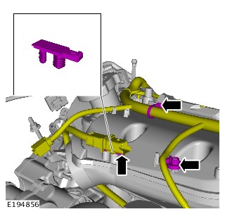
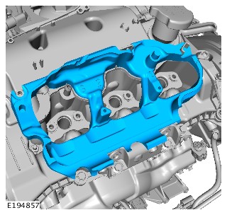
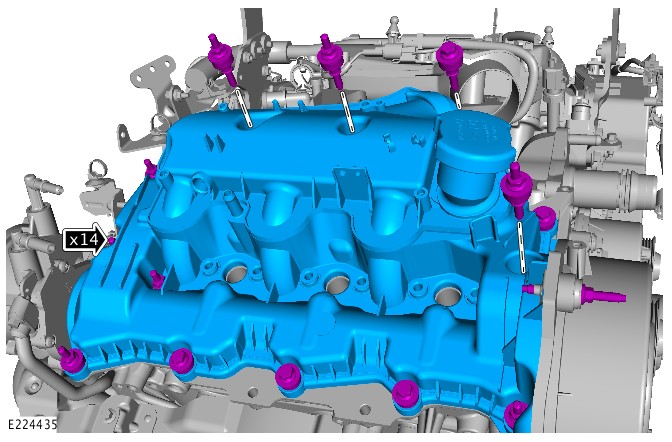
-
CAUTIONS:
-
Use only a plastic scraper when removing the sealing material.
-
Use lint free cloth.
-
Make sure that the mating faces are clean and free of corrosion and foreign material.
-
Installation of the valve cover and tightening must be carried out within 7 minutes of applying the sealant.
NOTES:-
(1) Right valve cover.
-
(2) Left valve cover.
Apply (0.35g) a small amount of gasket sealant (Loctite 5900 or Hylosil sealant) in each location as shown on the illustration. Install the valve cover immediately after applying the sealant. -
-
CAUTION:
Make sure that the mating faces are clean and free of corrosion and foreign material.
- Install a new left valve cover gasket
- Install, but do not fully tighten the 14 left valve cover bolts.

- Install the fuel rail mounting bracket.
Torque: 23Nm
- Install the right valve cover mounting bracket.
Torque: 10Nm
- Install the plastic fixings.
- Install the pin.
Torque: 9Nm
-
- Install the Noise, Vibration and Harshness material.
- Install the wiring harness to the right valve cover.
- Install the vacuum harness.
-
- Install new fuel injector retaining clamps.
- Install new O-ring seals.
- Install new sealing washers.
- Install the fuel injectors.
Torque: 9Nm
-
- Install the fuel injector leak off pipes.
- Connect the fuel injector wiring harness.
- Install the right fuel rail.
Refer to:Right Fuel Rail (303-04A Fuel Charging and Controls - TDV6 3.0L Diesel /TDV6 3.0L Diesel - Gen 1.5/TDV6 3.0L Diesel - Gen 2, Removal and Installation).
-
- Install the vacuum harness.
- Connect the electrical connectors.
- Install the throttle body.
Refer to:Intake Air Shutoff Throttle (303-04A Fuel Charging and Controls - TDV6 3.0L Diesel /TDV6 3.0L Diesel - Gen 1.5/TDV6 3.0L Diesel - Gen 2, Removal and Installation).
- Fill the drain the cooling system.
Refer to:Cooling System Partial Draining and Vacuum Filling (303-03A Engine Cooling - TDV6 3.0L Diesel /TDV6 3.0L Diesel - Gen 1.5/TDV6 3.0L Diesel - Gen 2, General Procedures).
- Connect the startup battery ground cable
Refer to:Specifications (414-00 Battery and Charging System - General Information, Specifications).
OIL COOLER (G1879930)
- 12.60.68
- OIL COOLER - RENEW
- 3000 CC, TDV6
- 4.60
- USED WITHINS
PART(S)
| STEP | PART NAME | QUANTITY |
|---|---|---|
| Installation Step 1 | Oil cooler O-ring seals | 1 |
| Installation Step 2 | Engine coolant outlet seal | 1 |
-
This procedure contains some variation in the illustrations depending on the vehicle specification, but the essential information is always correct.
-
This procedure contains illustration showing certain components removed to provide extra clarity.
- Drain the cooling system.
Refer to:Cooling System Partial Draining and Vacuum Filling (303-03A Engine Cooling - TDV6 3.0L Diesel /TDV6 3.0L Diesel - Gen 1.5/TDV6 3.0L Diesel - Gen 2, General Procedures).
- Disconnect the startup battery ground cable.
Refer to:Specifications (414-01 Battery, Mounting and Cables, Specifications).
- Remove the right valve cover.
Refer to:Right Valve Cover (303-01A Engine - TDV6 3.0L Diesel /TDV6 3.0L Diesel - Gen 1.5/TDV6 3.0L Diesel - Gen 2, Removal and Installation).
- Remove the oil filter.
Refer to:Oil Filter Element (303-01A Engine - TDV6 3.0L Diesel /TDV6 3.0L Diesel - Gen 1.5/TDV6 3.0L Diesel - Gen 2, Removal and Installation).
- Remove the glow plugs.
Refer to:Glow Plugs (303-07C Glow Plug System - TDV6 3.0L Diesel /TDV6 3.0L Diesel - Gen 1.5/TDV6 3.0L Diesel - Gen 2, Removal and Installation).
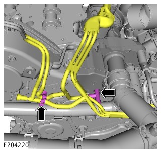

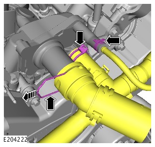
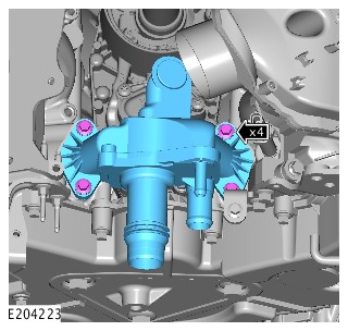

-
Install the oil cooler.CAUTION:
Install new seals.
Torque: 10Nm
-
Install the coolant outlet.CAUTION:
Install new seals.
Torque: 10Nm
- Connect the coolant hoses.
- Install the vacuum reservoir.
Torque: 10Nm
- Connect the vacuum tubes.
- Install the glow plugs.
Refer to:Glow Plugs (303-07C Glow Plug System - TDV6 3.0L Diesel /TDV6 3.0L Diesel - Gen 1.5/TDV6 3.0L Diesel - Gen 2, Removal and Installation).
- Install a new oil filter.
Refer to:Oil Filter Element (303-01A Engine - TDV6 3.0L Diesel /TDV6 3.0L Diesel - Gen 1.5/TDV6 3.0L Diesel - Gen 2, Removal and Installation).
- Install the right valve cover.
Refer to:Right Valve Cover (303-01A Engine - TDV6 3.0L Diesel /TDV6 3.0L Diesel - Gen 1.5/TDV6 3.0L Diesel - Gen 2, Removal and Installation).
- Connect the startup battery ground cable.
Refer to:Specifications (414-01 Battery, Mounting and Cables, Specifications).
- Fill the cooling system.
Refer to:Cooling System Partial Draining and Vacuum Filling (303-03A Engine Cooling - TDV6 3.0L Diesel /TDV6 3.0L Diesel - Gen 1.5/TDV6 3.0L Diesel - Gen 2, General Procedures).
- Check and top-up the engine oil.
Removal
ENGINE - TDV6 3.0L DIESEL /TDV6 3.0L DIESEL - GEN 1.5/TDV6 3.0L DIESEL - GEN 2 (G1509157)
- 12.41.01.99
- ENGINE AND ANCILLARIES - REMOVE FOR ACCESS AND REFIT
- 3000 CC, TDV6, DIESEL, WITH PARTICULATE FILTER, WITH DIESEL EXHAUST FLUID, IC
- 9.90
- USED WITHINS
SPECIAL TOOL(S)
303-021
Engine support bracket
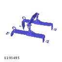
303-1141
Engine lifting kit
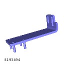
303-1141-01
Engine lifting bracket - Rear
Before disconnecting any components, make sure the area is clean and free from foreign material. When disconnected all openings must be sealed.
Some variation in the illustrations may occur, but the essential information is always correct.
- Disconnect the startup battery ground cable.
Refer to:Specifications (414-00 Battery and Charging System - General Information, Specifications).
- Raise and support the vehicle on a suitable 2 post lift.
Refer to:Lifting (100-02 Jacking and Lifting, Description and Operation).
- Position the hood into the service position.
Refer to:Specifications (501-02 Front End Body Panels, Specifications).
- Drain the cooling system.
Refer to:Cooling System Partial Draining and Vacuum Filling (303-03B Engine Cooling - V6 S/C 3.0L Petrol, General Procedures).
- Remove the intake air shutoff throttle.
Refer to:Intake Air Shutoff Throttle (303-04A Fuel Charging and Controls - TDV6 3.0L Diesel /TDV6 3.0L Diesel - Gen 1.5/TDV6 3.0L Diesel - Gen 2, Removal and Installation).
- Remove the transmission.
Refer to:Transmission - TDV6 3.0L Diesel /TDV6 3.0L Diesel - Gen 1.5/TDV6 3.0L Diesel - Gen 2, Vehicles With: Twin Speed Transfer Case (307-01A Automatic Transmission/Transaxle - Vehicles With: 8HP70 8-Speed Automatic Transmission AWD, Removal).
- Remove the front right halfshaft.
Refer to:Front Right Halfshaft (205-04 Front Drive Halfshafts, Removal and Installation).
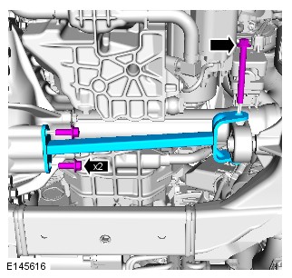
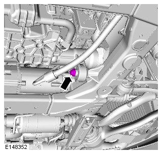
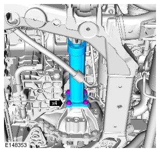
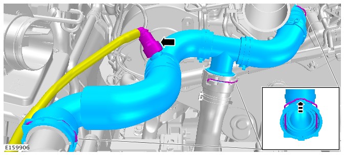
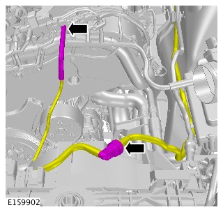
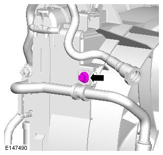
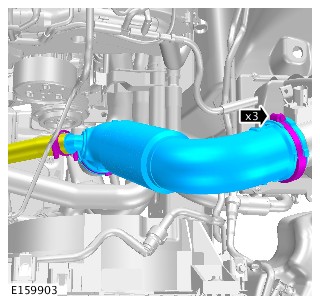
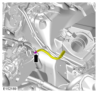
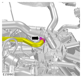
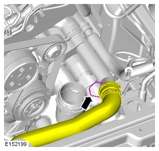
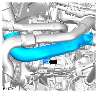

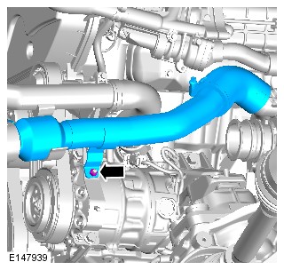
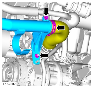

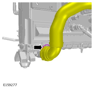
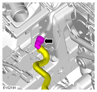
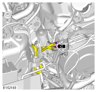
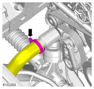
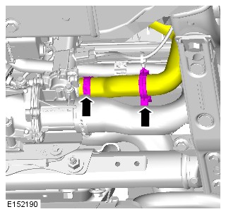
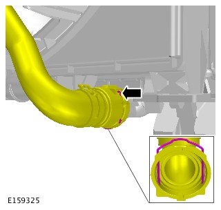
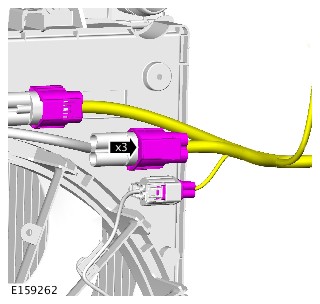
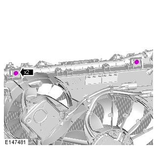
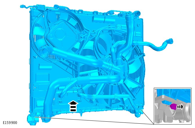


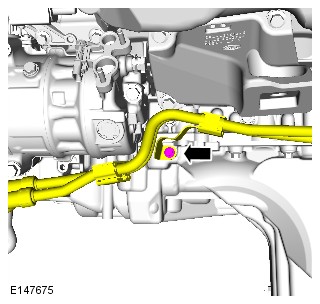
- Remove the accessory drive belt.
Refer to:Accessory Drive Belt - Vehicles Without: Dynamic Suspension (303-05A Accessory Drive - TDV6 3.0L Diesel /TDV6 3.0L Diesel - Gen 1.5/TDV6 3.0L Diesel - Gen 2, Removal and Installation).
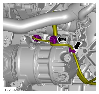
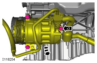
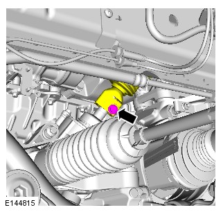
- Remove the secondary bulkhead center panel.
Refer to:Secondary Bulkhead Center Panel - TDV6 3.0L Diesel /TDV6 3.0L Diesel - Gen 1.5/TDV6 3.0L Diesel - Gen 2 (501-02 Front End Body Panels, Removal and Installation).

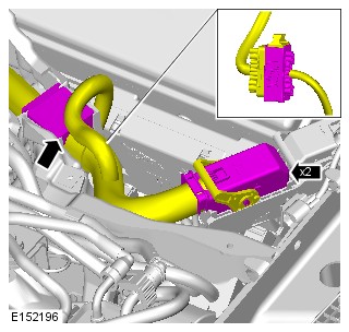
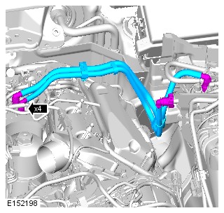
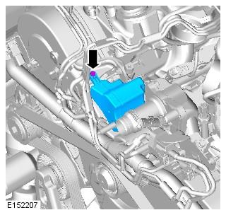
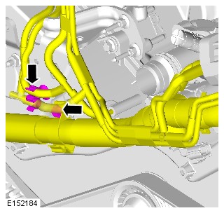
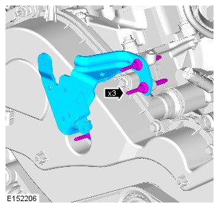
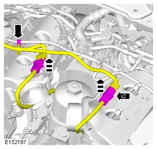
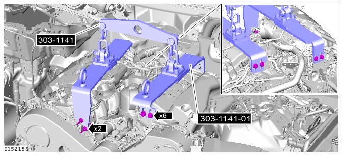
-
- Install the special tool.
Special Tool(s): 303-021
- Install the special tool.
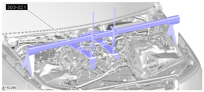
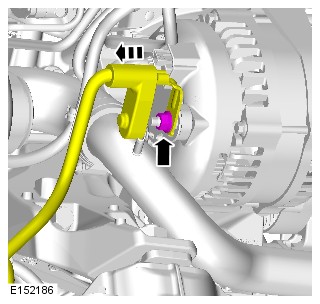
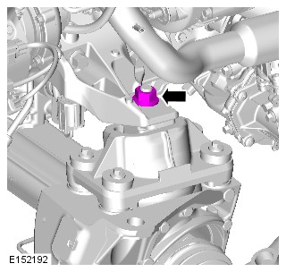
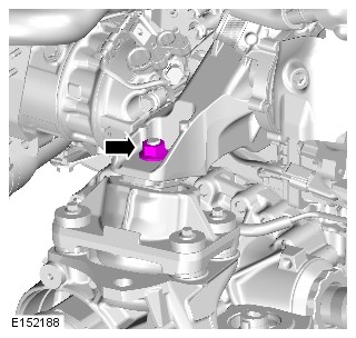
-
- Remove the special tool.
Special Tool(s): 303-021
- Remove the special tool.
-
WARNING:
This step requires the aid of another technician.
CAUTION:Be prepared to collect escaping fluids.
Carefully and progressively raise and remove the engine.
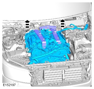
Disassembly
ENGINE - TDV6 3.0L DIESEL /TDV6 3.0L DIESEL - GEN 1.5/TDV6 3.0L DIESEL - GEN 2 (G1509157)
- 12.41.01.99
- ENGINE AND ANCILLARIES - REMOVE FOR ACCESS AND REFIT
- 3000 CC, TDV6, DIESEL, WITH PARTICULATE FILTER, WITH DIESEL EXHAUST FLUID, IC
- 9.90
- USED WITHINS
SPECIAL TOOL(S)
303-021
Engine support bracket
303-1141
Engine lifting kit
303-1141-01
Engine lifting bracket - Rear
Before disconnecting any components, make sure the area is clean and free from foreign material. When disconnected all openings must be sealed.
Some variation in the illustrations may occur, but the essential information is always correct.
- Disconnect the startup battery ground cable.
Refer to:Specifications (414-00 Battery and Charging System - General Information, Specifications).
- Raise and support the vehicle on a suitable 2 post lift.
Refer to:Lifting (100-02 Jacking and Lifting, Description and Operation).
- Position the hood into the service position.
Refer to:Specifications (501-02 Front End Body Panels, Specifications).
- Drain the cooling system.
Refer to:Cooling System Partial Draining and Vacuum Filling (303-03B Engine Cooling - V6 S/C 3.0L Petrol, General Procedures).
- Remove the intake air shutoff throttle.
Refer to:Intake Air Shutoff Throttle (303-04A Fuel Charging and Controls - TDV6 3.0L Diesel /TDV6 3.0L Diesel - Gen 1.5/TDV6 3.0L Diesel - Gen 2, Removal and Installation).
- Remove the transmission.
Refer to:Transmission - TDV6 3.0L Diesel /TDV6 3.0L Diesel - Gen 1.5/TDV6 3.0L Diesel - Gen 2, Vehicles With: Twin Speed Transfer Case (307-01A Automatic Transmission/Transaxle - Vehicles With: 8HP70 8-Speed Automatic Transmission AWD, Removal).
- Remove the front right halfshaft.
Refer to:Front Right Halfshaft (205-04 Front Drive Halfshafts, Removal and Installation).
- Remove the accessory drive belt.
Refer to:Accessory Drive Belt - Vehicles Without: Dynamic Suspension (303-05A Accessory Drive - TDV6 3.0L Diesel /TDV6 3.0L Diesel - Gen 1.5/TDV6 3.0L Diesel - Gen 2, Removal and Installation).
- Remove the secondary bulkhead center panel.
Refer to:Secondary Bulkhead Center Panel - TDV6 3.0L Diesel /TDV6 3.0L Diesel - Gen 1.5/TDV6 3.0L Diesel - Gen 2 (501-02 Front End Body Panels, Removal and Installation).
-
- Install the special tool.
Special Tool(s): 303-021
- Install the special tool.
-
- Remove the special tool.
Special Tool(s): 303-021
- Remove the special tool.
-
WARNING:
This step requires the aid of another technician.
CAUTION:Be prepared to collect escaping fluids.
Carefully and progressively raise and remove the engine.
LONG/STRIPPED ENGINE ASSEMBLY RENEW - TDV6 3.0L DIESEL - GEN 2 - TWIN TURBOCHARGER (G2194109)
- 12.41.02
- STRIPPED ENGINE - REMOVE ENGINE, CHANGE OVER ANCILLARY EQUIPMENT AND REFIT
- 3000 CC, TDV6, TWIN TURBOCHARGER FITTED, DIESEL, WITH PARTICULATE FILTER, WITH DIESEL EXHAUST FL
- 15.90
- USED WITHINS
SPECIAL TOOL(S)
100-012
Slide Hammer
303-1123
Locking Tool, Flywheel
310-213
Fuel Injector Removal Adapter
JLR-303-1523
Remover/Installer, Camshaft Rear Pulley
Before disconnecting any components, make sure the area is clean and free from foreign material. When disconnected all openings must be sealed.
- This procedure contains some variation in the illustrations depending on the vehicle specification, but the essential information is always correct.
- This procedure contains illustrations showing certain components removed to provide extra clarity.
- Remove the engine.
Refer to:Engine (303-01A Engine - TDV6 3.0L Diesel /TDV6 3.0L Diesel - Gen 1.5/TDV6 3.0L Diesel - Gen 2, Removal).
-
Install the special tool.Install the Special Tool(s): 303-1123
-
Remove the special tool.Remove the Special Tool(s): 303-1123
-
Install the special tool.Install the Special Tool(s): JLR-303-1523Torque: 10Nm
-
- Install the special tool.
Install the Special Tool(s): JLR-303-1523
- Remove and discard the camshaft sprocket bolt.
- Install the special tool.
- Remove the special tool.
Remove the Special Tool(s): JLR-303-1523
SHORT ENGINE ASSEMBLY RENEW - TDV6 3.0L DIESEL - GEN 2 (G2430980)
SPECIAL TOOL(S)
303-1123
Locking Tool, Flywheel
303-1124
Holding Tool, Camshaft Front Pulley
303-1126
Timing Peg, Camshaft Pulley
GENERAL EQUIPMENT
| EQUIPMENT NAME |
|---|
| Engine stand |
- This procedure contains some variation in the illustrations depending on the vehicle specification, but the essential information is always correct.
- This procedure contains illustrations showing certain components removed to provide extra clarity.
-
Remove the engine and ancillaries.NOTE:
Do not complete steps 2 - 4 of the procedure. The drive plate needs to remain on the engine.
Refer to:Long/Stripped Engine Assembly Renew - TDV6 3.0L Diesel - Gen 2 - Mono Turbocharger (303-01A Engine - TDV6 3.0L Diesel /TDV6 3.0L Diesel - Gen 1.5/TDV6 3.0L Diesel - Gen 2, Disassembly).Refer to:Long/Stripped Engine Assembly Renew - TDV6 3.0L Diesel - Gen 2 - Twin Turbocharger (303-01A Engine - TDV6 3.0L Diesel /TDV6 3.0L Diesel - Gen 1.5/TDV6 3.0L Diesel - Gen 2, Disassembly).
- Install the engine assembly on to a suitable engine stand.
General Equipment: Engine stand

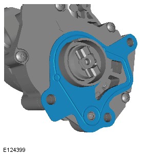


-
Install the 2 camshaft locking pins.Install the Special Tool(s): 303-1126
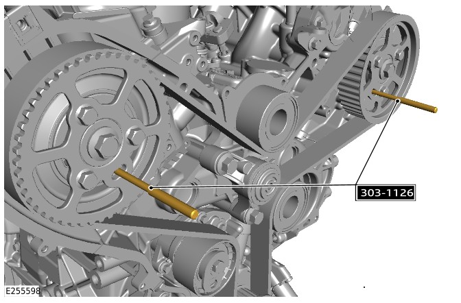
-
CAUTION:
Do not attempt to loosen the 6 bolts using the special tools to prevent the camshaft pulleys from turning. Failure to follow this instruction may result in damage to the special tools or engine.
NOTE:Do not loosen the 6 bolts more than 2 turns.
Using a suitable tool to prevent the camshaft pulleys from turning, loosen the 6 bolts.


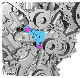

-
Install the special tool.Install the Special Tool(s): 303-1123
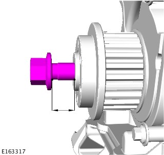
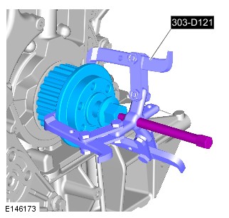
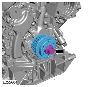

-
Remove the special tool.Remove the Special Tool(s): 303-1123
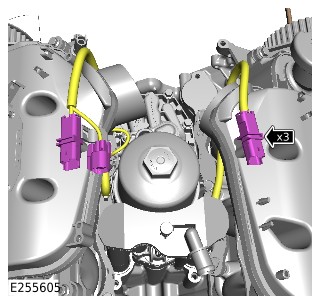
-
- Remove the special tool.
Remove the Special Tool(s): 303-1126
- Remove the 3 bolts.
- Remove the right camshaft drive pulley.
- Remove the special tool.

-
- Install the special tool.
Install the Special Tool(s): 303-1124
- Install the 3 bolts.
Torque: 20Nm
- Install the special tool.
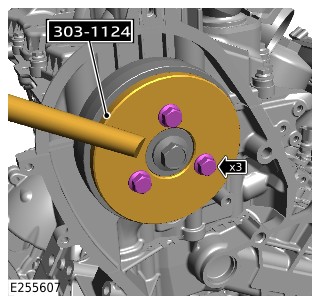
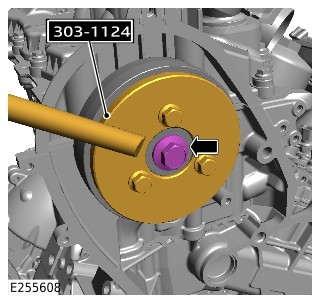
-
- Remove the 3 bolts.
- Remove the special tool.
Remove the Special Tool(s): 303-1124
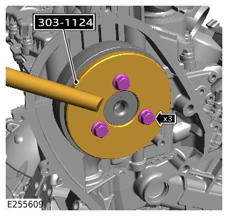
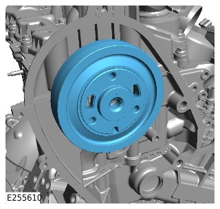
-
- Remove the special tool.
Remove the Special Tool(s): 303-1126
- Remove the 3 bolts.
- Remove the left camshaft drive pulley.
- Remove the special tool.
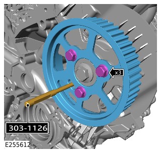
-
- Install the special tool.
Install the Special Tool(s): 303-1124
- Install the 3 bolts.
Torque: 20Nm
- Install the special tool.
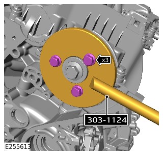
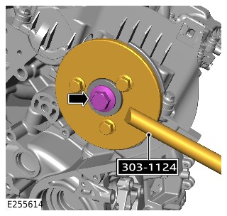
-
- Remove the 3 bolts.
- Remove the special tool.
Remove the Special Tool(s): 303-1124
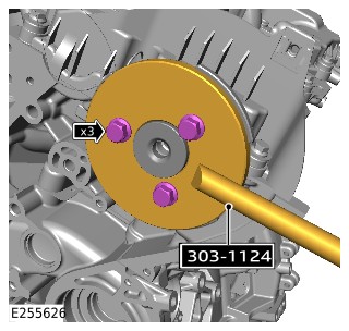
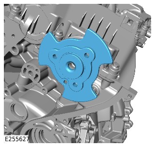
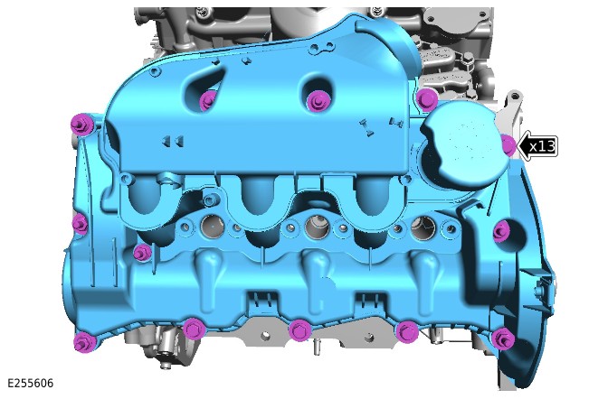

- Repeat steps 32 - 34 for the other side.
- Repeat steps 38 - 42 for the other side.


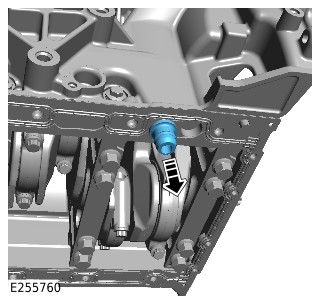

- remove the short engine assembly from the engine stand.
General Equipment: Engine stand
Assembly
LONG/STRIPPED ENGINE ASSEMBLY RENEW - TDV6 3.0L DIESEL - GEN 2 - TWIN TURBOCHARGER (G2194110)
- 12.41.02
- STRIPPED ENGINE - REMOVE ENGINE, CHANGE OVER ANCILLARY EQUIPMENT AND REFIT
- 3000 CC, TDV6, TWIN TURBOCHARGER FITTED, DIESEL, WITH PARTICULATE FILTER, WITH DIESEL EXHAUST FL
- 15.90
- USED WITHINS
SPECIAL TOOL(S)
303-1123
Locking Tool, Flywheel
310-212
Rear End Accessory Drive (READ) belt Timing Tool
JLR-303-1523
Remover/Installer, Camshaft Rear Pulley
GENERAL EQUIPMENT
| EQUIPMENT NAME |
|---|
| Engine stand |
PART(S)
| STEP | PART NAME | QUALIFICATION | QUANTITY |
|---|---|---|---|
| Step 11 | Engine coolant outlet upper O-ring seal | All vehicles | 2 |
| Step 12 | Coolant pump inlet O-ring seal | All vehicles | 1 |
| Step 13 | Crankshaft mass damper bolt(s) | All vehicles | 6 |
| Step 15 | Engine coolant pump gasket | All vehicles | 1 |
| Step 19 | Camshaft sprocket bolt | All vehicles | 1 |
| Step 38 | Fuel injector refit kit | All vehicles | 6 |
| Step 44 | Fuel rail balance pipe | All vehicles | 1 |
| Step 57 | Turbocharger oil supply pipe | All vehicles | 1 |
| Step 58 | Oil scavenge pipe gasket | All vehicles | 1 |
| Step 58 | Oil pan scavenge reservoir tube O-ring seal(s) | All vehicles | 1 |
| Step 59 | Turbocharger coolant pipes to turbocharger gasket | All vehicles | 1 |
| Step 60 | Exhaust manifold gasket | All vehicles | 1 |
| Step 60 | Exhaust manifold nuts | All vehicles | 6 |
| Step 62 | Turbocharger oil return pipe gasket(s) | All vehicles | 2 |
| Step 65 | Exhaust manifold to EGR valve gasket | 2 High pressure EGR valves | 1 |
| Step 68 | Exhaust manifold gasket | All vehicles | 1 |
| Step 68 | Exhaust manifold nuts | All vehicles | 6 |
| Step 69 | Turbocharger oil return pipe gasket(s) | All vehicles | 1 |
| Step 69 | Turbocharger oil return pipe seals | All vehicles | 1 |
| Step 71 | EGR pipe to exhaust manifold gasket | All vehicles | 1 |
| Step 73 | Camshaft position sensor | All vehicles | 1 |
| Step 87 | EGR valve outlet pipe gasket (vehicles without EGR cooler) | 2 High pressure EGR valves | 1 |
| Step 99 | Exhaust manifold cross-over pipe studs | All vehicles | 2 |
| Step 100 | Exhaust manifold cross-over pipe studs | All vehicles | 3 |
| Step 101 | Exhaust manifold cross-over pipe gaskets | All vehicles | 2 |
| Step 101 | Exhaust manifold cross-over pipe nuts | All vehicles | 3 |
| Step 102 | Exhaust manifold cross-over pipe bolt | All vehicles | 1 |
| Step 102 | Exhaust manifold cross-over pipe nuts | All vehicles | 2 |
| Step 108 | Flexplate bolts | All vehicles | 8 |
- This procedure contains some variation in the illustrations depending on the vehicle specification, but the essential information is always correct.
- This procedure contains illustrations showing certain components removed to provide extra clarity.
- Install the engine on to a suitable engine stand.
General Equipment: Engine stand
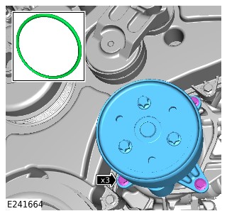
-
CAUTION:
Failure to use special tool JLR-303-1523 might result in engine damage/failure.
Install the special tool.Install the Special Tool(s): JLR-303-1523Torque: 10Nm
-
- Install the special tool.
Install the Special Tool(s): JLR-303-1523
- Tighten the camshaft pulley bolt.
TorqueStage1: 80NmStage2: 80°
- Install the special tool.
- Remove the special tools.
Remove the Special Tool(s): JLR-303-1523
-
CAUTION:
Make sure that the Rear End Accessory Drive (READ) belt tensioner tang is correctly located to the READ belt rear cover. Failure to follow this instruction may result in damage to the engine.
NOTE:Make sure that the READ belt tensioner locking pin is not removed until the READ belt tensioner is fully installed.
- Install the Rear End Accessory Drive (READ) belt tensioner.
- Install and tighten the bolt.
Torque: 23Nm

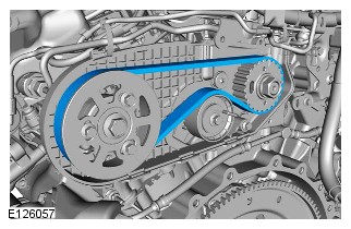
-
Install the special tool.Install the Special Tool(s): 310-212

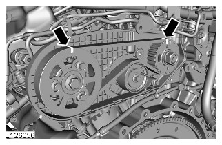


- Remove the special tool.
Remove the Special Tool(s): 310-212
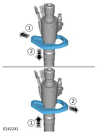
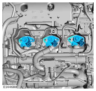
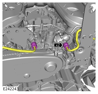
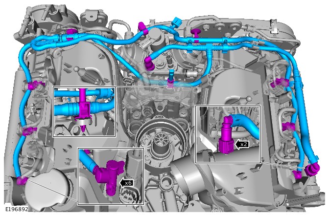
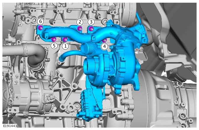
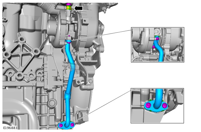
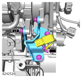
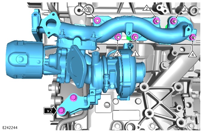

-
CAUTION:
The Camshaft Position Sensor (CMP) sensor tip must rest on one of the 3 webs on the back of the camshaft pulley. Incorrect installation may result in the CMP sensor being damaged.
NOTES:-
Only turn the engine in the normal direction of rotation.
-
Timing belt cover shown removed for clarity.
-
Apply light finger pressure to the rear of the CMP sensor when tightening the bolt.
- Rotate the engine until the camshaft pulley hub is visible through the CMP housing.
- Install the new CMP sensor until it rests on the camshaft pulley hub.
- Install and tighten the CMP sensor bolt.
Torque: 10Nm
-
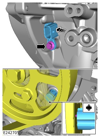
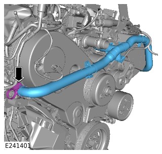
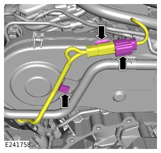
-
- Tighten the 5 exhaust manifold cross over pipe nuts.
Torque: 23Nm
- Tighten the exhaust manifold cross over pipe bolt.
Torque: 23Nm
- Tighten the 5 exhaust manifold cross over pipe nuts.
- Remove the engine from the suitable engine stand.
General Equipment: Engine stand
-
Install the special tool.Install the Special Tool(s): 303-1123
-
Remove the special tool.Remove the Special Tool(s): 303-1123
- Install the engine.
Refer to:Engine (303-01A Engine - TDV6 3.0L Diesel /TDV6 3.0L Diesel - Gen 1.5/TDV6 3.0L Diesel - Gen 2, Installation).
SHORT ENGINE ASSEMBLY RENEW - TDV6 3.0L DIESEL - GEN 2 (G2430981)
SPECIAL TOOL(S)
303-1117
Timing Peg, Automatic Transmission
303-1121A
Installer, Crankshaft Seal
303-1122
Installer, Crankshaft Front Seal
303-1123
Locking Tool, Flywheel
303-1124
Holding Tool, Camshaft Front Pulley
303-1126
Timing Peg, Camshaft Pulley
GENERAL EQUIPMENT
| EQUIPMENT NAME |
|---|
| Engine stand |
PART(S)
| STEP | PART NAME | QUANTITY |
|---|---|---|
| Step 3 | Engine oil pump | 1 |
| Step 17 | Oil pan dowel | 2 |
| Step 20 | Oil cooler O-ring seals | 4 |
| Step 21 | Drive plate bolts | 8 |
| Step 24 | Crankshaft pulley bolt | 1 |
| Step 29 | Cylinder head bolts | 16 |
| Step 37 | Camshaft seal | 1 |
| Step 38 | Camshaft seal | 2 |
| Step 64 | Timing belt and tensioner kit | 1 |
| Step 65 | Timing belt | 1 |
| Step 75 | Timing belt cover gasket | 1 |
| Step 76 | Brake vacuum pump gasket | 1 |
- This procedure contains some variation in the illustrations depending on the vehicle specification, but the essential information is always correct.
- This procedure contains illustrations showing certain components removed to provide extra clarity.
- Install the short engine assembly on to a suitable engine stand.
General Equipment: Engine stand
- A new oil pump must be installed.
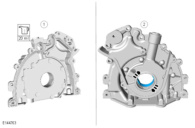
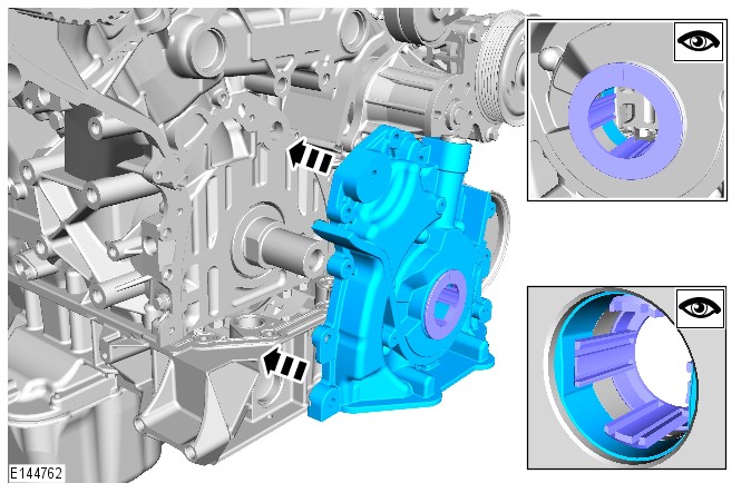
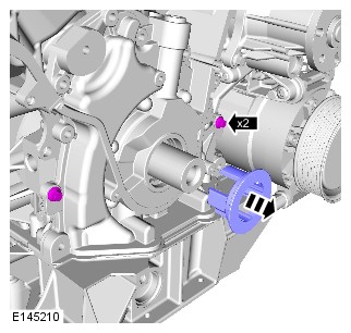
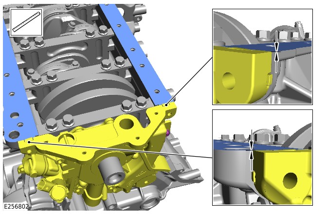
-
Install the front crankshaft oil seal onto the special tool.Special Tool(s): 303-1122
-
Reposition the crankshaft front seal along the special tool.Special Tool(s): 303-1122
-
Install the special tool to the crankshaft.Install the Special Tool(s): 303-1122
-
Remove the special tool.Remove the Special Tool(s): 303-1122
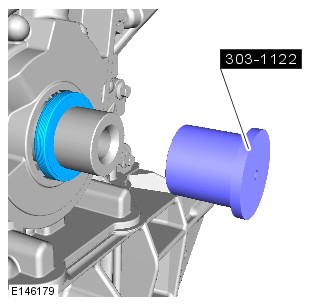
-
Install the special tool to the crankshaft.Install the Special Tool(s): 303-1121A
-
CAUTION:
Make sure that the front crankshaft oil seal is seated 1 mm under flush.
NOTE:Use the crankshaft pulley bolt with the special tool.
- Using the special tool. install the front crankshaft oil seal.
Install the Special Tool(s): 303-1121A
- Wait 10 seconds before continuing to step 15.
- Using the special tool. install the front crankshaft oil seal.
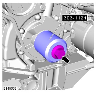
- Remove the special tool.
Remove the Special Tool(s): 303-1121A
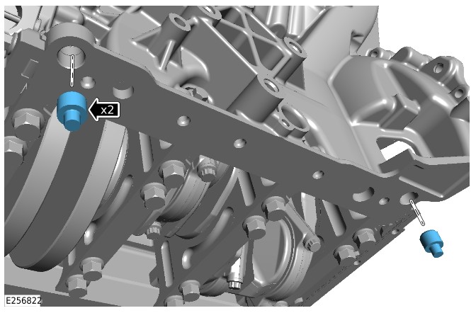
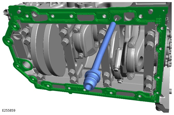
-
Install the special tool.Install the Special Tool(s): 303-1123
-
Remove the special tool.Remove the Special Tool(s): 303-1123
-
-
Rotate the crankshaft assembly until the special tool can be installed.CAUTION:
Make sure the correct special tool location hole is used, as illustrated.
- Install the special tool.
Install the Special Tool(s): 303-1117
-
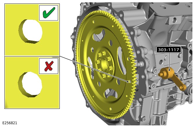
-
CAUTION:
Only use a plastic scrapper to clean off the old gasket.
- Clean and inspect the cylinder head.
- Check the cylinder head face for distortion, across the center and from corner to corner. Note the maximum value.
Refer to:Cylinder Head Distortion (303-00 Engine System - General Information, General Procedures).Refer to:Specifications (303-01A, Specifications).
- If the cylinder head requires machining, this must be completed by a local engineering company.
-
Install the head gaskets supplied with the short block assembly.CAUTION:
Make sure that the mating faces are clean and free of corrosion and foreign material.
- Repeat steps 27 - 33 for the other cylinder head.
-
- Lubricate the camshaft journals with clean engine oil prior to installation.
Refer to:Specifications (303-01 Engine - TDV6 3.0L Diesel - Gen 2/TDV6 3.0L Diesel /TDV6 3.0L Diesel - Gen 1.5, Specifications).
- Install the left camshaft assembly.
- Make sure the camshaft keyways are aligned to the 12 o'clock position.
- Install and tighten the 2 camshaft chain tensioner bolts.
Torque: 10Nm
- Lubricate the camshaft journals with clean engine oil prior to installation.
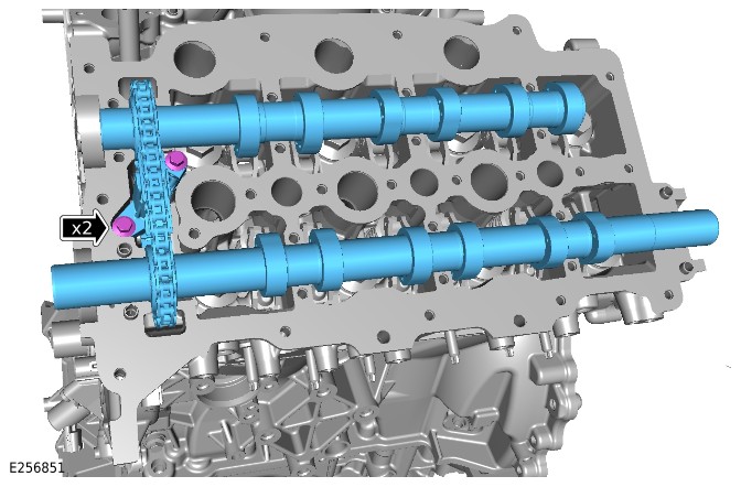
-
- Lubricate the camshaft journals with clean engine oil prior to installation.
Refer to:Specifications (303-01 Engine - TDV6 3.0L Diesel - Gen 2/TDV6 3.0L Diesel /TDV6 3.0L Diesel - Gen 1.5, Specifications).
- Install the right camshaft assembly.
- Make sure the camshaft keyways are aligned to the 12 o'clock position.
- Install and tighten the 2 camshaft chain tensioner bolts.
Torque: 10Nm
- Lubricate the camshaft journals with clean engine oil prior to installation.
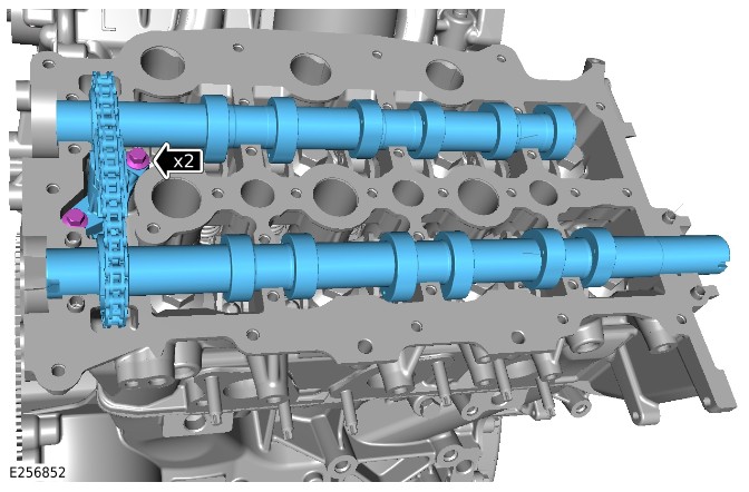
-
- Install the 7 left camshaft caps.
- Install and tighten 14 camshaft cap bolts in the following sequence.
TorqueStage1: Camshaft Cap D: 5NmStage2: Camshaft Cap C: 5NmStage3: Camshaft Cap B: 5NmStage4: Camshaft Cap A: 5NmStage5: Camshaft Cap F: 5NmStage6: Camshaft Cap G: 5NmStage7: Camshaft Cap J: 5Nm
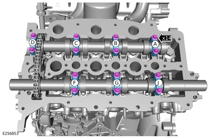
-
- Install the 7 right camshaft caps.
- Install and tighten the 14 camshaft cap bolts in the following sequence.
TorqueStage1: Camshaft Cap 9: 5NmStage2: Camshaft Cap 8: 5NmStage3: Camshaft Cap 7: 5NmStage4: Camshaft Cap 6: 5NmStage5: Camshaft Cap 4: 5NmStage6: Camshaft Cap 3: 5NmStage7: Camshaft Cap 2: 5Nm
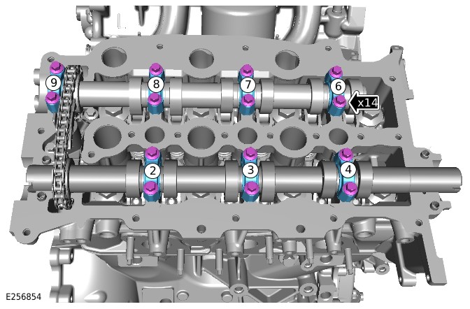
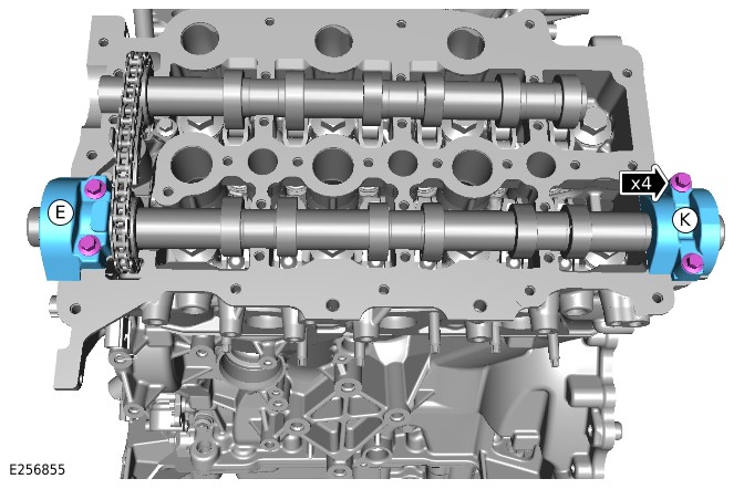
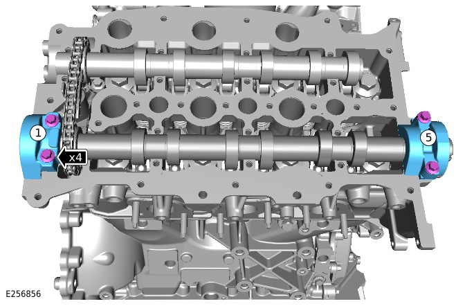
-
- Install the special tool.
Install the Special Tool(s): 303-1124
- Install the 3 bolts.
Torque: 22Nm
- Install the special tool.
-
- Remove the 3 bolts.
- Remove the special tool.
Remove the Special Tool(s): 303-1124
-
CAUTION:
Do not attempt to tighten the 3 bolts using the special tool to prevent the camshaft pulley from turning. Failure to follow this instruction may result in damage to the special tools or engine.
- Install the left camshaft drive pulley.
- Install and tighten the 3 bolts.
Torque: 22Nm
- Install the special tool.
Install the Special Tool(s): 303-1126
-
- Install the special tool.
Install the Special Tool(s): 303-1124
- Install the 3 bolts.
Torque: 22Nm
- Install the special tool.
-
- Remove the 3 bolts.
- Remove the special tool.
Remove the Special Tool(s): 303-1124
-
CAUTION:
Do not attempt to tighten the 3 bolts using the special tool to prevent the camshaft pulley from turning. Failure to follow this instruction may result in damage to the special tools or engine.
- Install the right camshaft drive pulley.
- Install and tighten the 3 bolts.
Torque: 22Nm
- Install the special tool.
Install the Special Tool(s): 303-1126
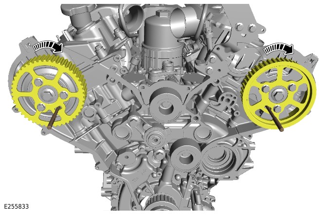
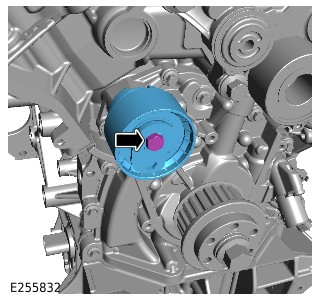
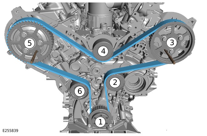
-
Remove the 2 camshaft locking pins.Remove the Special Tool(s): 303-1126
-
Remove the special tool.Remove the Special Tool(s): 303-1117
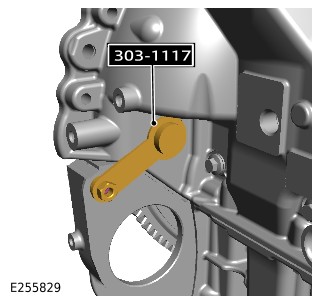
-
Install the special tool.Install the Special Tool(s): 303-1117
-
- Install the 2 camshaft locking pins.
Install the Special Tool(s): 303-1126
- If the special tools can not be installed, continue to the next step.
- If the special tools can be installed, continue to step 74.
- Install the 2 camshaft locking pins.
-
- If the special tools can not be installed, slacken the camshaft pulley bolts and rotate the camshaft pulley hub until the special tool can be installed.
- Tighten the camshaft pulley bolts.
Torque: 22Nm
- Repeat steps 68 - 72.
- Remove the special tools.
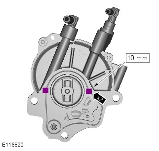
-
Install the engine and ancillaries.NOTES:
-
Twin turbocharger - Do not complete steps 111 - 113 of the procedure.
-
Mono turbocharger - Do not complete steps 109 - 111 of the procedure.
Refer to:Long/Stripped Engine Assembly Renew - TDV6 3.0L Diesel - Gen 2 - Twin Turbocharger (303-01 Engine - TDV6 3.0L Diesel - Gen 2/TDV6 3.0L Diesel /TDV6 3.0L Diesel - Gen 1.5, Assembly).Refer to:Long/Stripped Engine Assembly Renew - TDV6 3.0L Diesel - Gen 2 - Mono Turbocharger (303-01 Engine - TDV6 3.0L Diesel - Gen 2/TDV6 3.0L Diesel /TDV6 3.0L Diesel - Gen 1.5, Assembly). -
303-03A: Engine Cooling - TDV6 3.0L Diesel /TDV6 3.0L Diesel - Gen 1.5/TDV6 3.0L Diesel - Gen 2
ENGINE COOLING - TDV6 3.0L DIESEL /TDV6 3.0L DIESEL - GEN 1.5/TDV6 3.0L DIESEL - GEN 2 (G1509363)
Fluid
Coolant must be collected into a clean container and can be reused if not contaminated.
| DESCRIPTION | SPECIFICATION |
|---|---|
| Land Rover premium cooling system fluid | Havoline XLC |
| Coolant concentration | 50% |
| Vehicles with block heater coolant concentration | 60% |
Capacity
| ITEM | LITRES |
|---|---|
| Vehicles equipped with 2 zone Air Conditioning (A/C) | 9.4 |
| Vehicles equipped with 2 zone A/C and Fuel Fired Booster Heater (FFBH) | 9.6 |
| Vehicles equipped with 4 zone A/C | 11.2 |
| Vehicles equipped with 4 zone A/C and FFBH | 11.4 |
| Hybrid Electric Vehicle (HEV) battery circuit | 1.5 |
| DESCRIPTION | NM | LB-FT | LB-IN |
|---|---|---|---|
| Coolant expansion tank bolt | 2.8 | - | 25 |
| Coolant outlet assembly bolts | 10 | 7 | - |
| Coolant pump bolts | 10 | 7 | - |
| Coolant pump pulley bolts | 25 | 18 | - |
| Thermostat housing bracket to fan shroud bolt | 5 | - | 44 |
| Thermostat housing bolts | 5 | - | 44 |
| Radiator drain plug | 3.5 | - | 31 |
| A/C pipes to condenser nuts | 8 | - | 71 |
| A/C pipe to fan shroud bolt | 7 | - | 62 |
| Charge air cooler pipe connector to fan shroud bolt | 8 | - | 71 |
| Charge air cooler hose clamp to fan shroud bolt | 7 | - | 62 |
| Engine cooling module bolts | 15 | 11 | - |
| Cooling fan shroud bolts | 7 | - | 62 |
| Transmission fluid cooler to fan shroud bolt | 7 | - | 62 |
| Coolant bleed screw(s) | 3 | - | 27 |
ENGINE COOLING - TDV6 3.0L DIESEL /TDV6 3.0L DIESEL - GEN 1.5/TDV6 3.0L DIESEL - GEN 2 (G1950019)
COMPONENT LOCATION - 1 OF 3 - FRONT VIEW
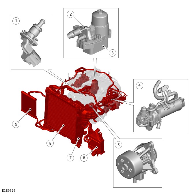
| ITEM | DESCRIPTION |
|---|---|
| 1 | Engine Coolant Temperature (ECT) sensor |
| 2 | Coolant outlet connector |
| 3 | Engine oil cooler |
| 4 | Low Pressure (LP) Exhaust Gas Recirculation (EGR) cooler |
| 5 | Variable coolant pump |
| 6 | Charge air cooler |
| 7 | Radiator |
| 8 | Charge air radiator |
| 9 | Auxiliary radiator |
COMPONENT LOCATION - 2 OF 3 - REAR VIEW
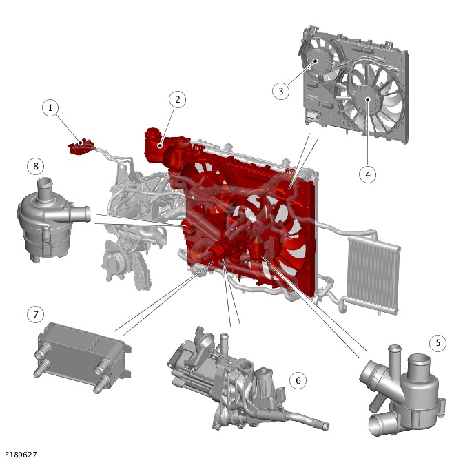
| ITEM | DESCRIPTION |
|---|---|
| 1 | Fuel cooler |
| 2 | Coolant expansion tank |
| 3 | Electric cooling fan - auxiliary |
| 4 | Electric cooling fan - main |
| 6 | Cooling fan shroud |
| 5 | Thermostat |
| 6 | High Pressure (HP) Exhaust Gas Recirculation (EGR) cooler |
| 7 | Automatic Transmission Fluid (ATF) cooler |
| 8 | Charge air coolant pump |
COMPONENT LOCATION - 3 OF 3 - ACTIVE GRILLE AIR SHUTTER - IF EQUIPPED
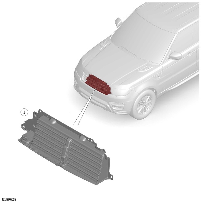
| ITEM | DESCRIPTION |
|---|---|
| 1 | Active grille air shutter |
The engine cooling system maintains the engine within an optimum temperature range under changing ambient and engine operating conditions.
The cooling system also provides:
- Heating for the passenger compartment. For additional information, refer to:
Heating and Ventilation (412-01 Climate Control, Description and Operation),Auxiliary Climate Control (412-02 Auxiliary Climate Control, Description and Operation).
- Cooling for the:
- Engine oil For additional information, refer to:Engine (303-01A Engine - TDV6 3.0L Diesel /TDV6 3.0L Diesel - Gen 1.5/TDV6 3.0L Diesel - Gen 2, Description and Operation).
- Fuel system For additional information, refer to:Fuel Tank and Lines (310-01A Fuel Tank and Lines - TDV6 3.0L Diesel /TDV6 3.0L Diesel - Gen 1.5/TDV6 3.0L Diesel - Gen 2, Description and Operation).
- Exhaust Gas Recirculation (EGR) system For additional information, refer to:Engine Emission Control (303-08A Engine Emission Control - TDV6 3.0L Diesel /TDV6 3.0L Diesel - Gen 1.5/TDV6 3.0L Diesel - Gen 2, Description and Operation).
- Primary turbocharger For additional information, refer to:Turbocharger (303-04B Fuel Charging and Controls - Turbocharger - TDV6 3.0L Diesel, Description and Operation).
- Automatic Transmission Fluid (ATF) For additional information, refer to:Transmission Cooling (307-02A Transmission/Transaxle Cooling - Vehicles With: 8HP70 8-Speed Automatic Transmission AWD, Description and Operation) / Transmission Cooling (307-02A Transmission/Transaxle Cooling - Vehicles With: 8HP70 8-Speed Automatic Transmission AWD, Description and Operation).
- Charge air coolerFor additional information, refer to:Intake Air Distribution and Filtering (303-12A Intake Air Distribution and Filtering - TDV6 3.0L Diesel /TDV6 3.0L Diesel - Gen 1.5/TDV6 3.0L Diesel - Gen 2, Description and Operation).
In some markets, an active grille air shutter is installed to reduce aerodynamic drag and engine warm up time.
THERMOSTAT
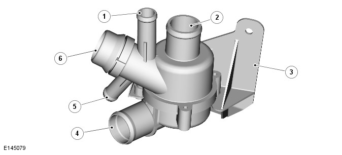
| ITEM | DESCRIPTION |
|---|---|
| 1 | Heater return hose connection |
| 2 | Bypass hose connection |
| 3 | Thermostat bracket |
| 4 | Lower hose connection |
| 5 | Coolant expansion tank return hose connection |
| 6 | Coolant pump coolant inlet connection |
A pressure relief type thermostat is located behind the radiator, on a bracket attached to the cooling fan shroud. The thermostat body contains a wax element and a spring loaded bypass valve.
The thermostat housing is connected to the following:
- The radiator lower hose
- The engine bypass hose
- The feed hose to the engine coolant pump
- The heater return hose
- The coolant expansion tank return hose.
The thermostat allows rapid engine warm-up by preventing coolant flow through the radiator and by limiting coolant flow through the cylinder block when the engine is cold. The thermostat is not a serviceable item and it can be replaced as an assembly.
RADIATOR
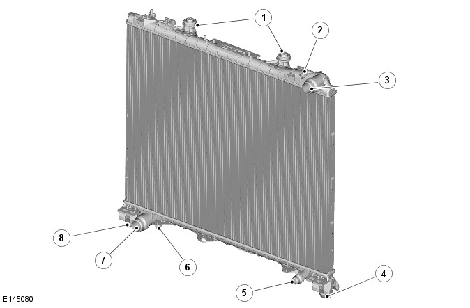
| ITEM | DESCRIPTION |
|---|---|
| 1 | Upper mounts |
| 2 | Vent hose connection |
| 3 | Upper hose connection |
| 4 | Lower mount |
| 5 | Automatic Transmission Fluid (ATF) cooler hose connection |
| 6 | Drain screw |
| 7 | Lower hose connection |
| 8 | Lower mount |
The radiator is a vertical-flow type with an aluminum core and plastic end tanks. The radiator is located in the vehicle by bushes attached to the end tanks. The lower bushes are installed in the front subframe. The upper bushes are installed in the front end carrier.
Upper and lower hose connections are incorporated into the upper and lower end tanks respectively. The lower end tank also incorporates a drain screw, and a connection for the coolant feed hose of the Automatic Transmission Fluid (ATF) cooler. The upper end tank incorporates a connection for a vent hose to the coolant expansion tank. The end tanks also incorporate mounting points for the cooling fan shroud and the Air Conditioning (A/C) condensor.
VARIABLE COOLANT PUMP
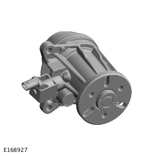
The variable coolant pump has a housing that supports a shaft with an impeller attached to one end and a drive hub at the other. The housing is attached to the front of the cylinder block with the impeller located in a pumping chamber. The variable coolant pump is driven by a pulley attached to the drive hub and driven by the accessory drive belt at engine speed. For additional information, refer to:Accessory Drive (303-05A Accessory Drive - TDV6 3.0L Diesel /TDV6 3.0L Diesel - Gen 1.5/TDV6 3.0L Diesel - Gen 2, Description and Operation).
The variable coolant pump has a shroud mechanism which can be used to create zero flow in the engine coolant circuit to enable accelerated engine warm-up. The operation of the shroud is controlled by the Powertrain Control Module (PCM) through a solenoid valve which is attached to the variable coolant pump housing with a screw. The solenoid valve is connected to the PCM through a hardwired connection. When the engine is cold and the engine speed is between 1900 RPM and 4800 RPM, the PCM activates the solenoid valve and the shroud moves to the 'no coolant flow' position. When the engine approaches the operating temperature the PCM deactivates the solenoid valve and the shroud retracts to its base position. This results full coolant flow from the coolant pump to the engine cooling system.
COOLANT EXPANSION TANK
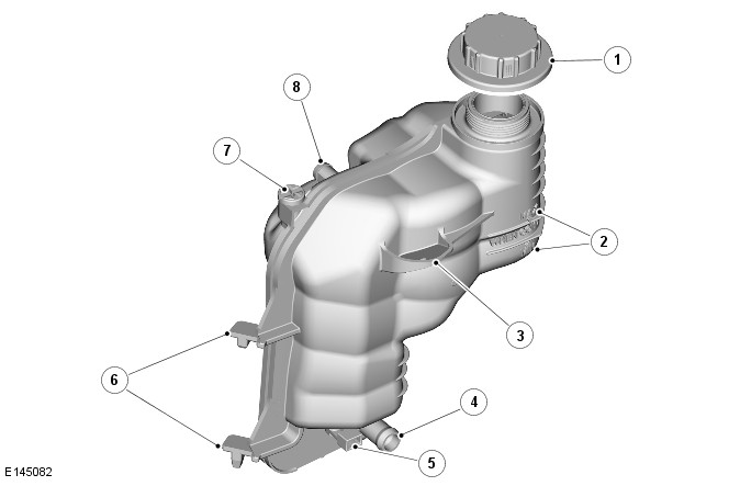
| ITEM | DESCRIPTION |
|---|---|
| 1 | Filler cap |
| 2 | MAX and MIN level markings |
| 3 | Mounting lug |
| 4 | Supply hose connection |
| 5 | Coolant level sensor |
| 6 | Mounting lugs |
| 7 | Bleed screw |
| 8 | Vent hose connection |
A pressurized expansion tank system is used which continuously separates the air from the cooling system and replenishes the system through a hose connected between the expansion tank and the thermostat. A continuous vent into the expansion tank, through a hose connected to the radiator, prevents air locks from forming in the cooling system.
The expansion tank is attached to the front end carrier in the front left corner of the engine compartment. A filler cap, bleed screw and level sensor are incorporated into the expansion tank.
The coolant expansion tank provides the following functions:
- The service fill.
- Engine coolant expansion during warm up.
- Air separation during operation.
- System pressurization by the filler cap.
- Coolant level sensing.
The coolant expansion tank has an air space of approximately 0.5 to 1 liter (1.06 to 2.11 US pints). The coolant expansion tank allow for the engine coolant expansion if the coolant above the maximum level. Minimum and maximum level markings are molded on the coolant expansion tank body.
The engine coolant level sensor locates in a sealed cavity at the bottom of the coolant expansion tank body. A float with an integral magnet is located inside the coolant expansion tank. The coolant level sensor contains a switch that reacts to the position of the magnetic float. The coolant level sensor is hardwired to the Body Control Module/Gateway Module (BCM/GWM).
The magnetic float is designed to float very close to the bottom of the tank, significantly below the MIN cold fill coolant level. The magnetic float in this position does not indicate float failure, for example sinking or sticking. The float has a travel distance of approximately 15 mm (0.59 in) from the bottom of the tank.
ELECTRIC COOLING FAN
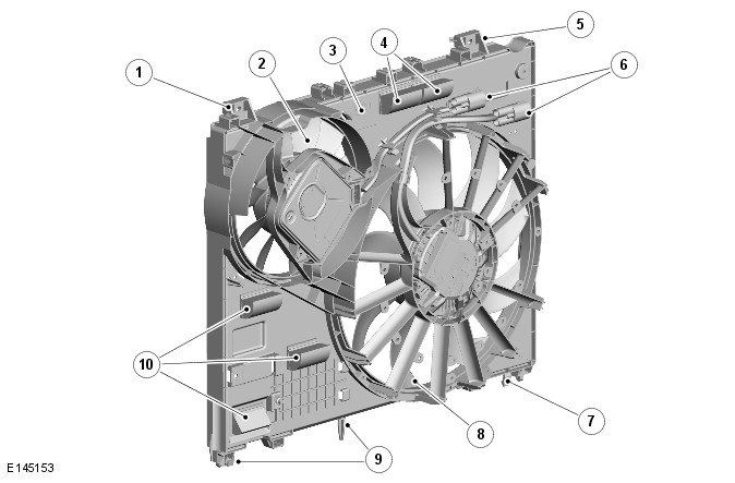
| ITEM | DESCRIPTION |
|---|---|
| 1 | Mounting lug |
| 2 | Electric cooling fan - auxiliary |
| 3 | Cooling fan shroud |
| 4 | Speed flaps |
| 5 | Mounting lug |
| 6 | Electrical connectors |
| 7 | Mounting lug |
| 8 | Electric cooling fan - main |
| 9 | Mounting lugs |
| 10 | Speed flaps |
Vehicles have two variable speed electric engine cooling fans to help regulate the coolant temperature. The fan shroud is attached to the rear of the radiator. On vehicles with a single engine cooling fan, a blanking plate is installed in place of the second fan. The shroud incorporates speed flaps, which pivot open to allow engine compartment cooling at speed.
Each electric cooling fan is operated by a control module, integrated into their electric motor, which is controlled by the PCM. Electrical connectors at the right side of the fan shroud provide the interface between the cooling fan harnesses and the vehicle wiring.
The control module of each electric cooling fan is provided with:
- A battery power supply from the Auxiliary Junction Box (AJB).
- An ignition signal from the PCM relay in the Engine Junction Box (EJB).
- A Pulse Width Modulation (PWM) signal from the PCM.
- A ground.
To control each electric cooling fan, the PCM varies the duty cycle of the PWM signal. The cooling fan control module translates the duty cycle into a fan target speed and sets the output current to the fan motor accordingly.
CHARGE AIR COOLANT PUMP
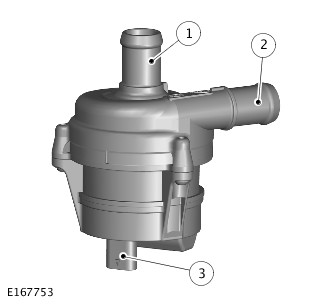
| ITEM | DESCRIPTION |
|---|---|
| 1 | Coolant inlet connection |
| 2 | Coolant outlet connection |
| 3 | Electrical connector |
The charge air coolant pump is an electric pump attached to the rear left side of the engine cooling fan shroud. Hoses connect the intake of the charge air coolant pump to the charge air radiator, and the outlet to the charge air cooler. An electrical connector provides the interface between the motor of the charge air coolant pump and the vehicle wiring. Operation of the charge air coolant pump is controlled by a PWM signal from the PCM.
CHARGE AIR COOLER
A charge air cooler is installed on the left side of the cooling pack, behind the left outer air intake in the front bumper. For additional information, refer to:Intake Air Distribution and Filtering (303-12A Intake Air Distribution and Filtering - TDV6 3.0L Diesel /TDV6 3.0L Diesel - Gen 1.5/TDV6 3.0L Diesel - Gen 2, Description and Operation).
CHARGE AIR RADIATOR
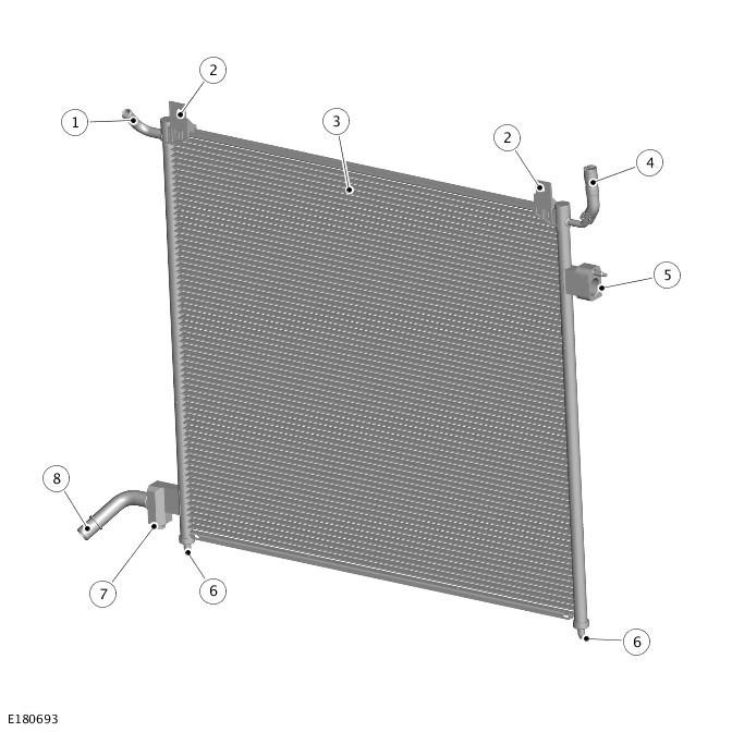
| ITEM | DESCRIPTION |
|---|---|
| 1 | Coolant expansion hose connection |
| 2 | Mounting bracket |
| 3 | Charge air radiator |
| 4 | Bleed screw |
| 5 | Coolant outlet connection |
| 6 | Mounting pin |
| 7 | Drain screw |
| 8 | Coolant inlet connection |
The charge air radiator is located between the radiator and the A/C condensor. The charge air radiator is attached to the A/C condensor with two pins at the bottom of the end tanks. Two brackets are attached to the top of the charge air radiator, which are providing the connection to the A/C condensor with two screws.
The right end tank comprises connections to the charge air coolant pump inlet and the engine cooling system. A drain plug is integrated into the bottom of the coolant inlet connection. The connection with the radiator on the top of the right end tank accommodates the thermal expansion and retraction, and enables filling and draining of the coolant in the charge air cooling system. The left end tank comprises a coolant outlet connection to the charge air cooler and a bleed screw.
AUXILIARY RADIATOR
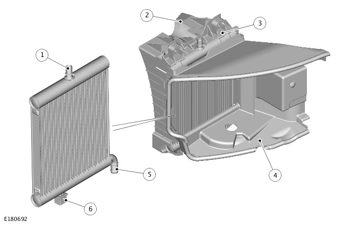
| ITEM | DESCRIPTION |
|---|---|
| 1 | Coolant inlet hose connection |
| 2 | Rear air duct |
| 3 | Radiator support bracket |
| 4 | Front air duct |
| 5 | Coolant outlet hose connection |
| 6 | Isolator |
The auxiliary radiator is located on the right side of the cooling pack, behind the outer air intake in the front bumper. The auxiliary radiator is installed in air ducts attached to the front bumper armature and the front end carrier. The lower end tank of the auxiliary radiator is located in the air duct by a spigot equipped with an isolator bush. The upper end tank of the auxiliary radiator is held in a support bracket in the air duct.
The auxiliary radiator is connected in parallel with the (main) radiator to increase the engine cooling capacity.
ENGINE COOLANT
The coolant is silicate free and must not be mixed with conventional engine coolant.
ACTIVE GRILLE AIR SHUTTER - IF EQUIPPED
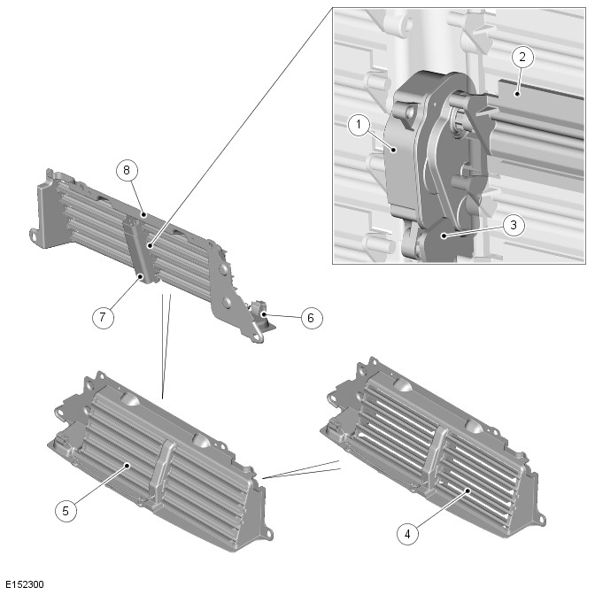
| ITEM | DESCRIPTION |
|---|---|
| 1 | Motor |
| 2 | Master vane |
| 3 | Support bracket |
| 4 | Vane - fully open (10 of) |
| 5 | Vane - fully closed (10 of) |
| 6 | Electrical connector |
| 7 | Vane link |
| 8 | Housing |
The active grille air shutter is installed behind the radiator grille and attached to the front end carrier. The active grille air shutter incorporates moveable vanes that control the air flow into the top half of the upstream main duct attached to the front of the cooling pack.
The vanes are installed in a housing in two groups of five and operated by an electric motor. The motor is held in a support bracket in the housing. The inboard hinge pin of one of the vanes (the master vane) is engaged in the output shaft of the motor. A lever on the inboard end of each vane is engaged in a motor link. When the motor turns the master vane, the motor link transfers the movement to the levers of the other nine vanes, which then turn in unison with the master vane.
The design of the vanes equalizes the wind loading on each side of the hinge pin, which reduces the resistance to turning when the vehicle is traveling at speed. A seal along the top edge of each vane provides sealing between adjacent vanes, and between the two upper vanes and the housing. The vanes can be set to one of 14 positions between fully closed and fully open, and have a range of movement of 80 degrees. During normal operation, for the vanes to move from fully closed to fully open takes approximately 30 seconds, and for the vanes to move from fully open to fully closed takes approximately 90 seconds.
Operation of the motor is controlled by the PCM, which communicates with the motor on a Local Interconnect Network (LIN) bus connection. Power for the motor is provided by a power supply from the PCM relay in the EJB.
COOLANT CIRCUIT FLOW
When the engine is running the coolant is circulated around the engine cooling system by the variable coolant pump. From the coolant pump, coolant flows through the cylinder block and the cylinder heads to the coolant outlet connector. Some of the coolant in the cylinder block is diverted through the engine oil cooler before returning to the coolant outlet connector. The primary turbocharger coolant inlet hose is connected to the cylinder block. Some of the coolant from the cylinder block flows through the turbocharger to the Exhaust Gas Recirculation (EGR) cooler outlet hose assembly.
From the coolant outlet connector, the majority of the coolant flows to the thermostat, either directly or through the radiator, depending on the temperature of the coolant and engine speed. The remainder of the coolant flows through the EGR coolers and the heater circuit to the thermostat. From the outlet of the thermostat the coolant flows to the coolant inlet connector on the left side of the cylinder block and back to the coolant pump.
A separate hose from the radiator allows extra-cooled coolant from the radiator to flow through the Automatic Transmission Fluid (ATF) cooler. The coolant from the ATF cooler returns to the system through a connector in the radiator lower hose.
The charge air cooling system is operationally independent of the engine cooling system, but connected to it at the radiator upper end tank. When the charge air coolant pump is running, the coolant flows from the pump outlet through the charge air cooler, the charge air radiator and back to the pump inlet connection.
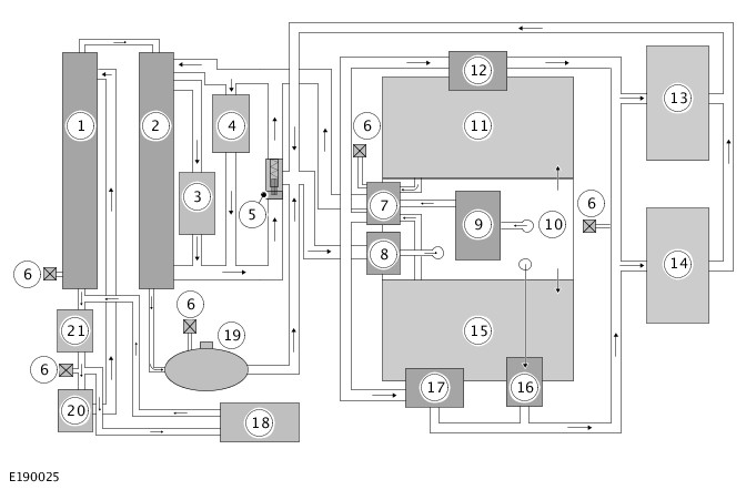
| ITEM | DESCRIPTION |
|---|---|
| 1 | Charge air radiator |
| 2 | Radiator |
| 3 | Automatic Transmission Fluid (ATF) cooler |
| 4 | Auxiliary radiator |
| 5 | Thermostat |
| 6 | Static bleed point (5 of) |
| 7 | Coolant outlet connection |
| 8 | Variable coolant pump |
| 9 | Engine oil cooler |
| 10 | Cylinder block |
| 11 | Cylinder head - Bank 1 |
| 12 | High Pressure (HP) Exhaust Gas Recirculation (EGR) cooler |
| 13 | Heater core - climate control assembly |
| 14 | Heater core - auxiliary climate control assembly - If equipped |
| 15 | Cylinder head - Bank 2 |
| 16 | Primary turbocharger |
| 17 | Low Pressure (LP) Exhaust Gas Recirculation (EGR) cooler |
| 18 | Fuel cooler |
| 19 | Coolant expansion tank |
| 20 | Charge air cooler |
| 21 | Charge air coolant pump |
THERMOSTAT
The thermostat is closed at temperatures below approximately 82 °C (179 °F). When the coolant temperature reaches approximately 82 °C (179 °F) the thermostat starts to open and is fully open at approximately 96 °C (204 °F). In this condition the full flow of coolant is directed through the radiator.
COOLANT LEVEL SENSOR
When the coolant level in the coolant expansion tank is sufficient, the magnetic float is in the top position. In this position the magnetic field closes the switch contacts in the coolant level sensor. When the coolant level drops significantly below the MIN cold fill coolant level, the magnetic float descends, thus the switch contacts disconnected. The open circuit is sensed by the Body Control Module/Gateway Module (BCM/GWM), which sends a signal to the Instrument Cluster (IC) to display the "Coolant Level Low" warning message. The message is sent on the High Speed (HS) Controller Area Network (CAN) chassis systems bus.
For additional information, refer to:Information and Message Center (413-08 Information and Message Center, Description and Operation).
ELECTRIC COOLING FAN
The Powertrain Control Module (PCM) determines when to operate the electric cooling fan from the Engine Coolant Temperature (ECT) sensor input and a cooling fan request from the HVAC Control Module. The PCM also adjusts the fan speed to compensate the ram effect of vehicle speed.
The PCM varies the duty cycle of the Pulse Width Modulation (PWM) signal to the engine cooling fan control module between 0 and 100% to operate the fan motor in one of four modes:
- Off
- Minimum speed - 750 RPM
- Linear variable speed between minimum and maximum speeds
- Maximum speed - 2820 RPM.
Under hot operating conditions, the electric cooling fan may continue to operate for up to 5 minutes after the engine has been switched off.
The engine cooling fan control module monitors for over and under input voltage, a stalled motor and a partially stalled motor. If it detects any of these faults the fan control module temporarily pulls the PWM signal to ground to notify the fault to the PCM. The length of time the PWM signal is pulled to ground varies between 2 and 8 seconds, depending on the fault. The control module repeats the notification process at 5 second intervals until the fault is cleared. If there is more than one fault, only the highest priority fault is notified to the PCM.
The fault priorities in descending order are the following:
- Over voltage
- Under voltage
- Stalled motor
- Partially stalled motor.
The PCM records a related Diagnostic Trouble Code (DTC) for faults notified by the fan control module and signals the BCM/GWM assembly through the FlexRay bus. The BCM/GWM assembly transmits the signal on the HS CAN chassis systems bus to the IC to display a warning message.
The nominal operating voltage for the engine cooling fans is 9 to 16 Volts. If the input voltage is outside of these limits, the fan control module stops operation of the electric cooling fan and notifies the PCM of the fault. After an under or over voltage occurs, the cooling fan operation is resumed when the input voltage increases to 9.5 Volts, or decreases to 15.5 Volts, respectively.
To check for a stalled motor, each time it supplies power to start the electric cooling fan the control module checks the cooling fan motor speed after 2 seconds. If the speed is zero, the fan control module determines the fan motor is stalled and tries a restart. For a restart, the fan control motor disconnects the power from the fan motor then immediately reconnects it at an increased current level. The fan control module will try up to six restarts of a stalled motor, increasing the output current each time. If the fan motor remains stalled after the sixth restart, the fan control module waits 40 seconds then notifies the PCM of the fault and begins the start process again.
To check for a partially stalled motor, while the fan is running the fan control module monitors the current draw against fan speed. If the current draw is over the limit for more than 10 seconds, the fan control module disconnects the power from the fan motor and notifies the PCM of the fault. After 40 seconds, the fan control module starts the motor again.
The fan control module incorporates a temperature sensor to prevent damage caused by excessive heat at high ambient temperatures. Operation of the fan control module is discontinued if the temperature reaches 135 °C (275 °F). Operation resumes when the temperature decreases to 120 °C (248 °F).
If a fault occurs with the ignition signal or the PWM signal, the fan control module adopts the following fan speeds:
| SIGNAL | FAULT | FAN SPEED | |
|---|---|---|---|
| IGNITION ON | IGNITION OFF | ||
| Pulse Width Modulation (PWM) | Duty cycle implausible | Maximum | Off |
| Pulse Width Modulation (PWM) | Frequency out of range | Maximum | Off |
| Pulse Width Modulation (PWM) | Open circuit | Maximum | Off |
| Pulse Width Modulation (PWM) | Short circuit to battery | Maximum (provided cooling fan is not damaged) | Off |
| Pulse Width Modulation (PWM) | Short circuit to ground | Maximum (provided cooling fan is not damaged) | Off |
| Ignition | Open circuit | Off | Off |
| Ignition | Short circuit to battery | According to Pulse Width Modulation (PWM) duty cycle | Maximum |
| Ignition | Short circuit to ground | Off (PCM relay fuse may blow) | Off |
CHARGE AIR COOLER
Electrical power for the charge air coolant pump is supplied from the PCM relay, located in the Engine Junction Box (EJB). When the relay is energized, it connects power from the battery to the charge air coolant pump. Operation of the charge air coolant pump is controlled by the PCM with a PWM signal. When the charge air coolant pump is running, coolant flows from the pump outlet through the charge air cooler, the charge air radiator and back to the pump inlet connection.
ACTIVE GRILLE AIR SHUTTER - IF EQUIPPED
During normal driving operation, the PCM determines vane position from the thermal condition of the vehicle, which is an output of the fan control logic.
The vane position depends on the following:
- The engine coolant temperature
- The Air Conditioning (A/C) demand
- The ambient air temperature
- The fuel temperature
- The Terrain Response® mode selection.
If vehicle speed reaches 180 km/h (112 mph) the vanes move to the fully open position. The vanes resume a calculated opening position when vehicle speed decreases to 140 km/h (87 mph).
In the case of engine cooling fan after-run, the vanes remain open. When the fan after-run ends, the vanes close and the motor will send a signal to the PCM indicating it is ready to power down.
When the PCM shuts down, the motor loses its memory. Therefore a calibration is required every time the ignition is switched on unless the PCM has remained active between ignition off and ignition on, for example engine cooling fan after-run.
Calibration only commences after the engine has started.
The calibration process opens and closes the vanes to find the end stops and range of motion between them. This range of movement is checked and if it is within the specified limits, the cycle is passed. This cycle can take up to 16 seconds.
The software allows for a total of six calibration attempts.
If the first attempt fails, as soon as a position demand exceeds 45%, it will complete the remaining five attempts, one after the other, until they either pass a calibration or fail all six attempts.
If the vanes pass the third calibration, for example the vanes had been frozen for the first two attempts and have since thawed out, the remaining attempts are saved for the rest of the drive cycle.
A 'Calibration Failed Fault' DTC will only be stored if the calibration fails from the first attempt and all attempts are used up.
The vanes will then be commanded to open as much as possible.
If the first calibration passes, then a 'Calibration Failed Fault' DTC cannot be set until the next drive.
The motor is very sensitive to voltage drops from engine cranking and may trigger a further calibration.
Jet wash mode allows the motor to fully open the vanes and then power down so that the radiator can be cleaned.
To activate jet wash mode:
- Start the engine.
- Stop the engine and turn the ignition off.
- Turn the ignition on (do not start the engine).
- Select Terrain Response® sand mode.
- Turn the ignition off.
This sequence prevents to enter jet wash mode accidentally when the ignition is turned off in sand mode.
The vanes will default to fully open if the calibration has been completed or not. (See calibration mode section above)
When the position feedback shows that the vanes are fully open, the motor will indicate to the PCM that it is ready to power down.
If there is a fault with the active grille air shutter, the 'Engine Over Temperature' warning is displayed in the Instrument Cluster (IC) message center. For each fault, a flag is set and after a calibrated de-bounce time, a DTC is stored in the PCM.
The following faults can be detected:
- Mechanical blockage fault – Motor encounters too much resistance and stalls. Max Torque = 0.7 - 0.8 Nm. When blocked, the motor will try to re-calibrate up to maximum number of attempts as described in the calibration section.
- Calibration failed fault – Fault stored if all calibration attempts have failed in that drive cycle.
- Electrical fault – Motor reports an internal electrical fault.
- Supply voltage fault – Motor supply voltage falls outside the range 7.5 V – 17.5 V.
- Thermal shutdown fault – Motor circuits exceed their inbuilt temperature threshold.
- Disconnect fault – Linkage between the motor and the vanes becomes disconnected.
- Local Interconnect Network (LIN) Bus communication fault and Node detection fault – A fault with the motor, its signal wire or its supply that causes a breakdown in signals to the PCM. If the motor is still operational and only the signal wire has a short circuit/open circuit, then the motor will fail safe fully open after 10 seconds of not receiving a signal.
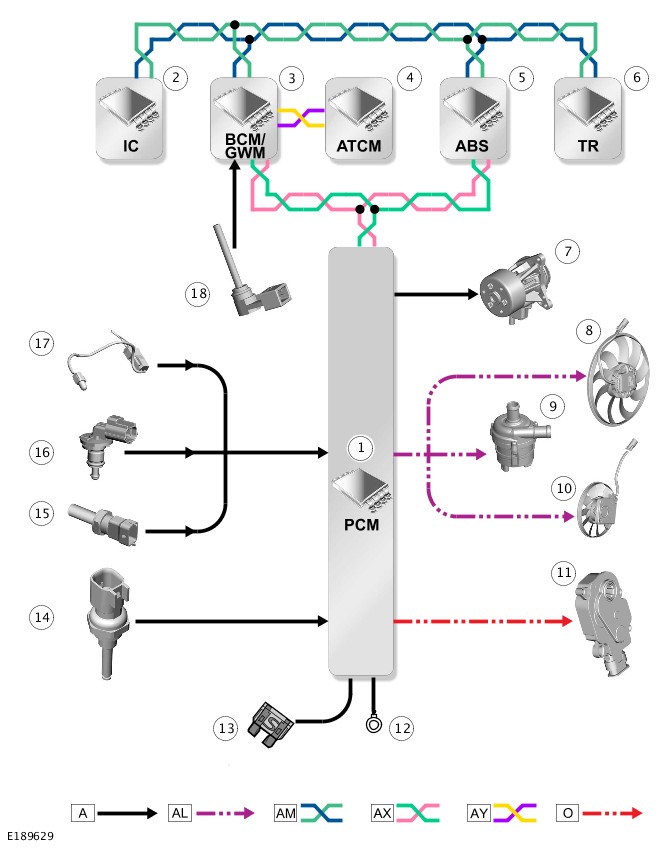
A = HARDWIRED; AL = PULSE WIDTH MODULATION (PWM); AM = HIGH SPEED (HS) CONTROLLER AREA NETWORK (CAN) CHASSIS SYSTEMS BUS; AX = FLEXRAY BUS; AY = HIGH SPEED (HS) CONTROLLER AREA NETWORK (CAN) POWER MODE ZERO BUS; O = LOCAL INTERCONNECT NETWORK LIN) BUS.
| ITEM | DESCRIPTION |
|---|---|
| 1 | Powertrain Control Module (PCM) |
| 2 | Instrument Cluster (IC) |
| 3 | Body Control Module/Gateway Module (BCM/GWM) Assembly |
| 4 | Terrain Response (TR) switchpack |
| 5 | Anti-lock Brake System (ABS) control module |
| 6 | HVAC Control Module |
| 7 | Variable coolant pump |
| 8 | Electric cooling fan - main |
| 9 | Charge air coolant pump |
| 10 | Electric cooling fan - auxiliary |
| 11 | Active grille air shutter motor - If equipped |
| 12 | Ground |
| 13 | Power supply |
| 14 | Cylinder head temperature sensor |
| 15 | Fuel temperature sensor |
| 16 | Engine Coolant Temperature (ECT) sensor |
| 17 | Ambient Air Temperature (AAT) sensor |
| 18 | Coolant level sensor |
Diagnosis and Testing
ENGINE COOLING - TDV6 3.0L DIESEL /TDV6 3.0L DIESEL - GEN 1.5/TDV6 3.0L DIESEL - GEN 2 (G1551114)
For a detailed description of the engine cooling system and operation, refer to the relevant Description and Operation section of the workshop manual. REFER to:Engine Cooling (303-03A Engine Cooling - TDV6 3.0L Diesel /TDV6 3.0L Diesel - Gen 1.5/TDV6 3.0L Diesel - Gen 2, Description and Operation).
Diagnosis by substitution from a donor vehicle is NOT acceptable. Substitution of control modules does not guarantee confirmation of a fault and may also cause additional faults in the vehicle being checked and/or the donor vehicle.
Check and rectify basic faults before beginning diagnostic routines involving pinpoint tests.
- Verify the customer concern.
- Visually inspect for obvious signs of mechanical or electrical damage.
Visual Inspection
| MECHANICAL | ELECTRICAL |
|---|---|
|
|
- If an obvious cause for an observed or reported concern is found, correct the cause (if possible) before proceeding to the next step.
- If the cause is not visually evident, verify the symptom and refer to the Symptom Chart, alternatively check for Diagnostic Trouble Codes (Diagnostic Trouble Code(s) (DTC)s) and refer to the DTC Index.
| SYMPTOM | POSSIBLE CAUSES | ACTION |
|---|---|---|
| Coolant loss |
|
|
| Overheating |
|
|
| Engine not reaching normal temperature |
|
|
| Message centre displays "Coolant Level Low" warning message |
|
|
| PINPOINT TEST A : COOLANT LEVEL SENSOR TESTS | |
|---|---|
|
NOTE:
The coolant expansion tank float is designed to be positioned near the bottom of the tank, significantly (more than 15mm) below the MIN cold fill level. A float in this position does NOT signify float failure (e.g. ‘sinking’ or ‘sticking’). Continue to follow the procedure as stated below. |
|
| A3: COOLANT LEVEL SENSOR TEST 3 - SENSOR CIRCUIT CONTINUITY CHECK | |
|---|---|
| TEST CONDITIONS | DETAILS/RESULTS/ACTIONS |
|
1
1. Replace the level sensor REFER to:Engine Coolant Level Switch (303-03A Engine Cooling - TDV6 3.0L Diesel /TDV6 3.0L Diesel - Gen 1.5/TDV6 3.0L Diesel - Gen 2, Removal and Installation).
|
|
|
2
Reconnect the engine coolant level sensor/switch assembly harness connector
|
|
|
|
Is the "Coolant Level Low" warning message displayed?
Yes
No
No further action required
|
For a list of Diagnostic Trouble Codes (DTCs) that could be set on this vehicle, please refer to Section 100-00. REFER to:Diagnostic Trouble Code Index - TDV6 3.0L Diesel /TDV6 3.0L Diesel - Gen 1.5/TDV6 3.0L Diesel - Gen 2, DTC: Powertrain Control Module B10A2-07 to P02D7-32 (100-00 General Information, Description and Operation).
COOLING SYSTEM DRAINING AND VACUUM FILLING (G1509365)
- 26.10.05
- COOLING SYSTEM DRAINING AND VACUUM FILLING
- 3000 CC, TDV6
- 1.80
- USED WITHINS
Since injury such as scalding could be caused by escaping steam or coolant, make sure the vehicle cooling system is cool prior to carrying out this procedure.
- Raise and support the vehicle on a suitable 2 post lift.
Refer to:Lifting (100-02 Jacking and Lifting, Description and Operation).
-
Refer to:Engine Undershield (501-02 Front End Body Panels, Removal and Installation).
-
Refer to:Engine Cover - TDV6 3.0L Diesel /TDV6 3.0L Diesel - Gen 1.5/TDV6 3.0L Diesel - Gen 2 (501-05 Interior Trim and Ornamentation, Removal and Installation).
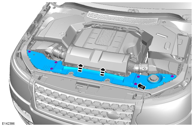
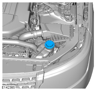
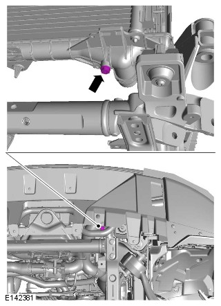
Steps 7-10 and 12-13 are only required if the vehicle is equipped with auxiliary climate control.
- Remove the front right wheel arch liner.
Refer to:Fender Splash Shield (501-02 Front End Body Panels, Removal and Installation).
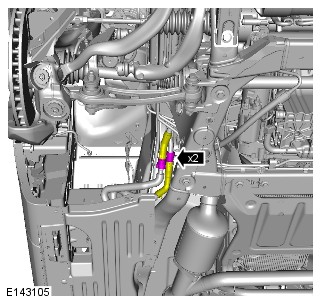
- Remove the rear left wheel arch liner.
Refer to:Rear Fender Splash Shield (501-08 Exterior Trim and Ornamentation, Removal and Installation).
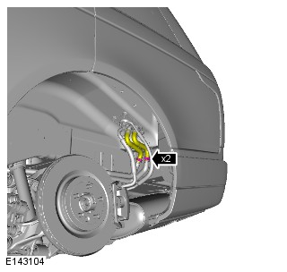
- Complete the fill procedure up to step 10 in the filling section 3 times. Fill the cooling system with clean water at the first 2 drains, At the final refill use a suitable measuring tool to make sure that the cooling system maintains the specified concentration mix.
-
CAUTIONS:
-
Engine coolant concentration must be maintained at 50%.
-
Vehicles with block heater coolant concentration must be maintained at 60%.
- Install the cooling system vacuum refill adapter to the expansion tank.
- Install the vacuum filler gauge to the cooling system vacuum refill adapter.
- Install the venturi tube assembly to the vacuum filler gauge.
-
-
NOTES:
-
Make sure the coolant supply valve is in the closed position on the vacuum filler gauge assembly.
-
The coolant vacuum fill tool needs an air pressure of 6 to 8 bar (87 to 116 psi) to operate correctly.
-
Small diameter or long airlines may restrict airflow to the coolant vacuum fill tool.
- Connect a regulated compressed air supply to the venturi tube assembly.
-
- Position the evacuated air hose into a container.
- Open the air supply valve.
-
Open the coolant supply valve for 2 seconds to prime the coolant supply hose.NOTE:
Make sure the coolant supply hose is positioned into a container of 50% mixture of Land Rover Premium Cooling System Fluid or equivalent, meeting Land Rover specification Halvoline XLC and fifty percent water. Make sure no air can enter the coolant supply hose.
- Apply air pressure progressively until the arrow on the vacuum filler gauge reaches the green segment.
- Disconnect the compressed air supply line.
-
Open the coolant supply valve and allow the coolant to be drawn into the system.NOTE:
Close the coolant supply valve when the coolant expansion tank MAX mark is reached or coolant movement has ceased.
- Remove the vacuum filler gauge and cooling system vacuum refill adapter assembly.
- Continue to fill the coolant expansion tank to the rim until the coolant level stops dropping.
- Start and run the engine.
- Set the heater controls to maximum.
- Increase the engine speed from idle to 3500 Revolutions Per Minute (RPM) until hot air is emitted from the front and rear face vents.
- Run the engine until the thermostat opens and hot air is emitted from the front and rear face vents.
- Switch the engine off and allow to cool.
- Visually check the engine and cooling system for signs of coolant leakage.
-
WARNING:
When releasing the cooling system pressure, cover the coolant expansion tank cap with a thick cloth.
CAUTIONS:-
Since injury such as scalding could be caused by escaping steam or coolant, make sure the vehicle cooling system is cool prior to carrying out this procedure.
-
Make sure the coolant level remains above the "COLD FILL RANGE" lower level mark.
Check and top-up the coolant if required.NOTE:When the cooling system is warm, the coolant will be approximately 10mm above the upper level mark on the expansion tank with the cap removed.
-
COOLING SYSTEM PARTIAL DRAINING AND VACUUM FILLING (G1798818)
- 26.10.09
- COOLING SYSTEM PARTIAL DRAINING AND VACUUM FILLING
- ALL DERIVATIVES
- 0.70
- USED WITHINS
SPECIAL TOOL(S)
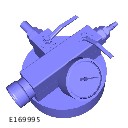
HU-919
Coolant System Vacuum Refill Kit
JLR-303-1634
Adaptor, Cooling System Vacuum Refill Kit
Since injury such as scalding could be caused by escaping steam or coolant, do not remove the filler cap from the coolant expansion tank while the system is hot.
-
The engine cooling system must be maintained with the correct concentration and type of engine coolant to prevent corrosion and frost damage. Failure to follow this instruction may result in damage to the engine.
-
Engine coolant will damage the paint finished surfaces. If spilt, immediately remove the coolant and clean the area with water.
-
This procedure contains some variation in the illustrations depending on the vehicle specification, but the essential information is always correct.
-
This procedure contains illustrations showing certain components removed to provide extra clarity.
- Raise and support the vehicle on a suitable 2 post lift.
Refer to:Lifting (100-02 Jacking and Lifting, Description and Operation).
- Remove engine undershield
Refer to:Engine Undershield (501-02 Front End Body Panels, Removal and Installation).
- Position a container to collect the fluid.
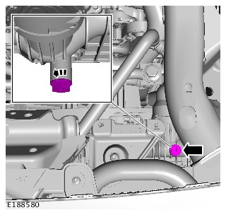
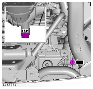
- Install the engine undershield.
Refer to:Engine Undershield (501-02 Front End Body Panels, Removal and Installation).
- Prepare a sufficient amount of coolant to the specified concentration.
Refer to:Specifications (303-03B Engine Cooling - V6 S/C 3.0L Petrol, Specifications).
-
CAUTION:
Make sure the air ejecting from the vac fill tool is pointed away from the vehicle.
NOTES:-
Make sure the coolant volume in the container is greater than the amount of coolant the vehicle requires.
-
Make sure the coolant supply valve is in the closed position on the special tool.
-
The special tool needs an air pressure of 6 to 8 bar (87 to 116 psi) to operate correctly.
-
Small diameter or long airlines may restrict airflow to the coolant vacuum fill tool.
- Install the special tools.
- Connect the hose from the vacuum refill adapter into a container of clean coolant, making sure the hose is submerged in coolant at all times during the fill operation.
- Connect a regulated compressed air supply to the venturi tube assembly.
- Install the cooling system vacuum refill adapter to the expansion tank.
-
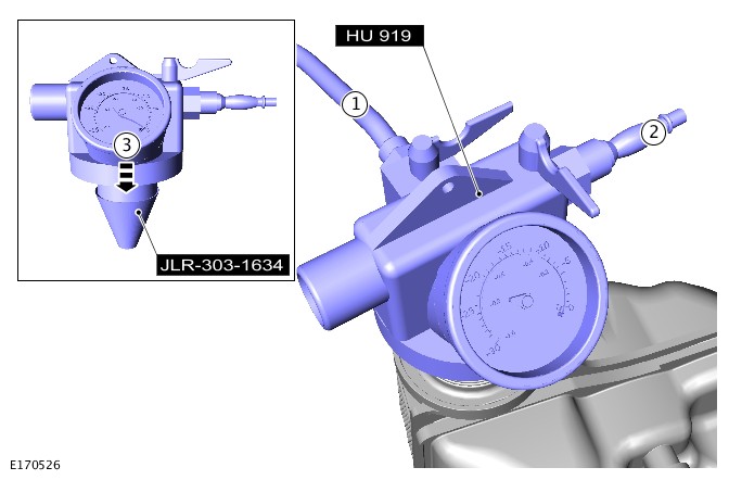
-
NOTE:
- Make sure the coolant supply valve is in the closed position on the vacuum filler gauge assembly.
- The coolant vacuum fill tool needs an air pressure of 6 to 8 bar (87 to 116 psi) to operate correctly.
- Small diameter or long airlines may restrict airflow to the coolant vacuum fill tool.
Open the air supply valve until -0.8 (-12 psi) Bar is shown on the gauge.
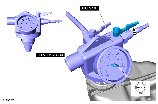
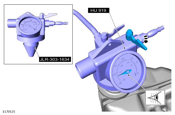
-
Open the coolant supply valve and allow the coolant to be drawn into the system until the header tank is at least half full and no further fluid is entering the tank. If the fill process appears to stop and the header tank is not yet half full then stop the fill process, remove the tool and restart the cooling system draining and vacuum filling procedure.
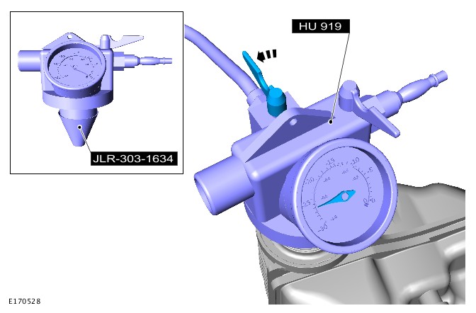
- Remove the special tools.
- Check and top-up the coolant to MAX.
-
CAUTIONS:
-
Make sure that the mating faces are clean and free of foreign material.
-
Do not exceed 1.0 bar (15 psi) when pressurizing the cooling system.
NOTE:If the pressure continues to drop after the initial tolerance, there is a coolant leak.
- Using the correct adapter connect the cooling system pressure test kit to the vehicle expansion tank.
- Slowly pressurize the cooling system until the pressure gauge reads 1.0 bar (15 psi).
- Make sure the cooling system holds pressure, and continue to the next step to bleed coolant from the bleed points.
-
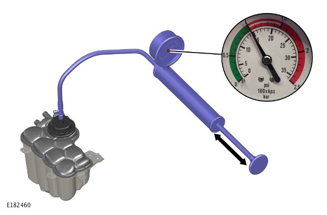
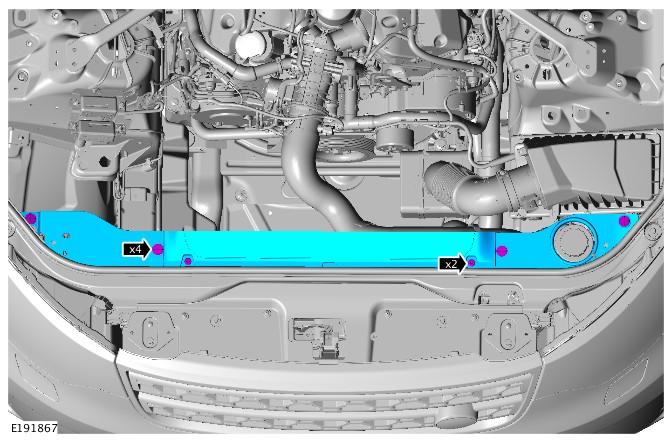
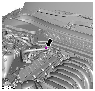
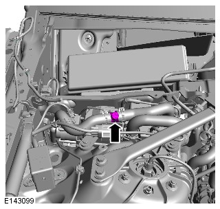
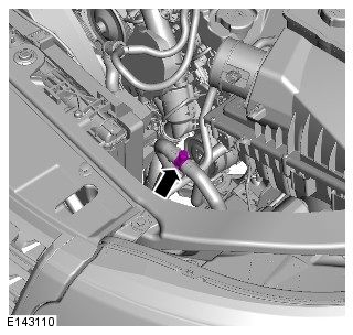
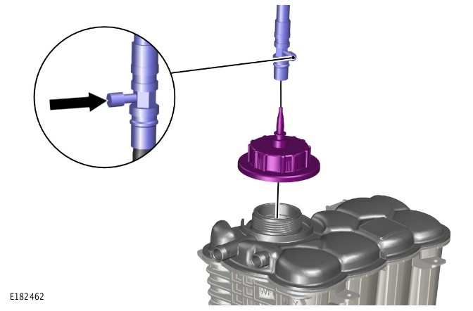
-
Install the coolant expansion tank cap.CAUTION:
Correct installation of the coolant expansion tank cap can be obtained by tightening the cap until 3 audible clicks are heard.
- Connect exhaust extraction hoses to the tail pipes.
-
- Select sand driving/dynamic mode if available.
- Make sure the interior heater is switched off.
- Start and run the engine and allow to idle for 30 seconds.
-
Hold the engine speed at 3500 rpm until the cooling fan starts to run and the thermostat opens, this will be evident as the radiator side coolant temperature will rise as coolant starts to flow around the radiator.CAUTION:
Make sure to observe the coolant level at all times and top up to the MAX mark as required.
- Switch the engine off and allow the engine to cool.
-
WARNING:
Release the cooling system pressure by slowly turning the coolant expansion tank cap a quarter of a turn. Cover the expansion tank cap with a thick cloth to prevent the possibility of scalding. Failure to follow this instruction may result in personal injury.
- Remove the coolant expansion tank pressure cap.
- Maintain the coolant level in the coolant expansion tank at the MAX mark.
-
Install the coolant expansion tank cap.CAUTION:
Correct installation of the coolant expansion tank cap can be obtained by tightening the cap until 3 audible clicks are heard.
ENGINE COOLING - TDV6 3.0L DIESEL /TDV6 3.0L DIESEL - GEN 1.5/TDV6 3.0L DIESEL - GEN 2
COOLING SYSTEM CONCENTRATION CHECK (G2154751)
GENERAL EQUIPMENT
| EQUIPMENT NAME |
|---|
| Refractometer / Hydrometer |
-
The engine cooling system must be maintained with the correct concentration and type of coolant solution to prevent corrosion and frost damage.
-
Engine coolant will damage the paint finished surfaces. If spilt, immediately remove the coolant and clean the area with water.
-
Never remove the coolant expansion tank cap under any circumstances while the engine is operating.
-
This procedure contains illustrations showing certain components removed to provide extra clarity.
-
This procedure contains some variation in the illustrations depending on the vehicle specification, but the essential information is always correct.
-
Raise the cover plate.General Equipment: Refractometer / Hydrometer
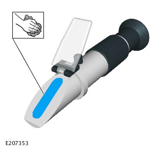
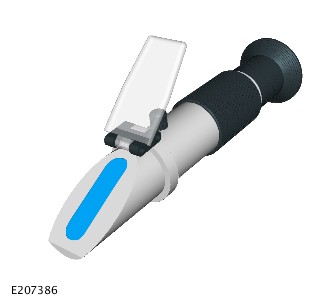
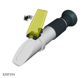
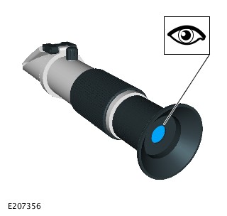
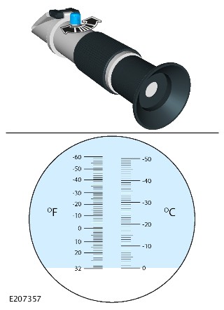
-
WARNING:
Release the cooling system pressure by slowly turning the coolant expansion tank cap a quarter of a turn. Cover the expansion tank cap with a thick cloth to prevent the possibility of scalding.
CAUTIONS:-
Be prepared to collect escaping coolant.
-
Since injury such as scalding could be caused by escaping steam or coolant, make sure the vehicle cooling system is cool prior to carrying out this procedure.
Remove the coolant expansion tank cap. -
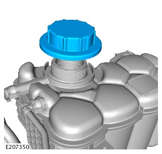
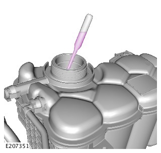
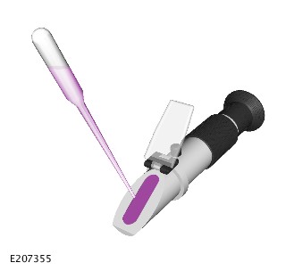
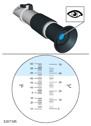
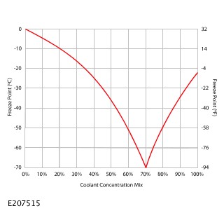
-
NOTE:
Coolant concentration mix % must divided by 100. 50% would be calculated as 0.5
- If the coolant concentration mix is below 50%, the following calculation steps must be followed.
- Step 1. Multiply the required coolant concentration mix % by the cooling system capacity.
- Step 2. Multiply the current coolant concentration mix % by the cooling system capacity.
- Step 3. Subtract the total of step 1 by total of step 2.
- Step 4. Subtract the current coolant concentration mix % from 1.
- Step 5. Divide the total of step 3 by the total of step 4.
- Drain the coolant quantity given by the calculations and replace with concentrated antifreeze.
- Proceed to Step 20.
-
NOTE:
Coolant concentration mix % must divided by 100. 50% would be calculated as 0.5
- If the coolant concentration mix is above 50%, the following calculation steps must be followed.
- Step 1. Multiply the current coolant concentration mix % by the cooling system capacity.
- Step 2. Multiply the required coolant concentration mix % by the cooling system capacity.
- Step 3. Subtract the total of step 1 by total of step 2.
- Step 5. Divide the total of step 3 by the current coolant concentration mix %.
- Drain the coolant quantity given by the calculations and replace with distilled water.
-
Install the coolant expansion tank pressure capCAUTION:
Correct installation of the coolant expansion tank cap can be obtained by tightening the cap until 3 audible clicks are heard.
Removal and Installation
ENGINE COOLING - TDV6 3.0L DIESEL /TDV6 3.0L DIESEL - GEN 1.5/TDV6 3.0L DIESEL - GEN 2
COOLANT EXPANSION TANK (G1509367)
- 26.15.01
- COOLANT EXPANSION TANK - RENEW
- ALL DERIVATIVES
- 0.30
- USED WITHINS
Since injury such as scalding could be caused by escaping steam or coolant, make sure the vehicle cooling system is cool prior to carrying out this procedure.
- Using a syringe, remove the cooling fluid from the expansion tank.
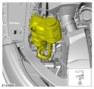
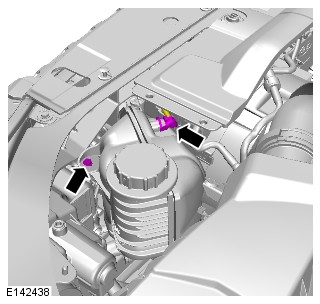
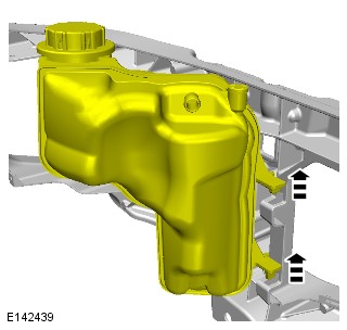
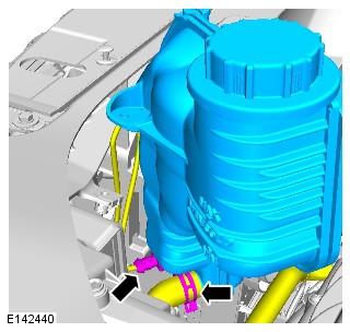
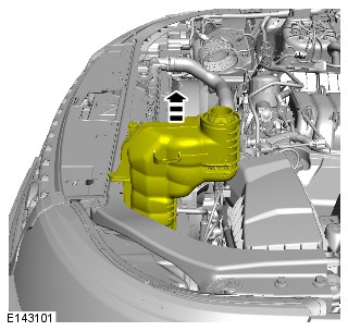
- Fill the cooling system, keeping coolant to the upper level mark of the expansion tank, until a steady stream of coolant is seen returning to the tank.
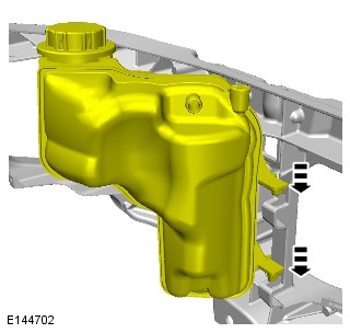
-
Check and top up the cooling system as required.CAUTION:
Make sure the coolant level remains above the "COLD FILL RANGE" lower level mark.
-
ENGINE COOLING - TDV6 3.0L DIESEL /TDV6 3.0L DIESEL - GEN 1.5/TDV6 3.0L DIESEL - GEN 2
COOLANT PUMP - TDV6 3.0L DIESEL - GEN 2 (G1780455)
REMOVAL AND INSTALLATION- 26.50.01
- COOLANT PUMP - RENEW
- 3000 CC, TDV6
- 1.10
- USED WITHINS
- 26.50.01
- COOLANT PUMP - RENEW
- 3000 CC, TDV6, DIESEL, IC
- 0.80
- USED WITHINS
REMOVALNOTE:Removal steps in this procedure may contain installation details.
- Disconnect the battery ground cable.
Refer to:Specifications (414-00 Battery and Charging System - General Information, Specifications).
-
Refer to:Cooling System Partial Draining and Vacuum Filling (303-03A Engine Cooling - TDV6 3.0L Diesel /TDV6 3.0L Diesel - Gen 1.5/TDV6 3.0L Diesel - Gen 2, General Procedures).
INSTALLATION- To install, reverse the removal procedure.
ENGINE COOLING - TDV6 3.0L DIESEL /TDV6 3.0L DIESEL - GEN 1.5/TDV6 3.0L DIESEL - GEN 2
COOLING FAN (G1509369)
REMOVAL AND INSTALLATION- 26.25.39
- ELECTRIC COOLING FAN AND SHROUD - RENEW
- 3000 CC, TDV6, DIESEL, IC
- 1.30
- USED WITHINS
REMOVALNOTES:-
Removal steps in this procedure may contain installation details.
-
Some variation in the illustrations may occur, but the essential information is always correct.
-
Some components shown removed for clarity.
The following step(s) applies to:All vehicles-
Refer to:Specifications (501-03 Body Closures, Specifications).
-
Refer to:Engine Undershield (501-02 Front End Body Panels, Removal and Installation).
-
Refer to:Cooling System Partial Draining and Vacuum Filling (303-03A, General Procedures).
-
Refer to:Coolant Expansion Tank (303-03 Engine Cooling - SDV6 3.0L Diesel - Hybrid Electric Vehicle, Removal and Installation).
The following step(s) applies to:Cold climate vehicles
The following step(s) applies to:Cold climate vehicles
The following step(s) applies to:All vehiclesINSTALLATION- To install, reverse the removal procedure.
ENGINE COOLING - TDV6 3.0L DIESEL /TDV6 3.0L DIESEL - GEN 1.5/TDV6 3.0L DIESEL - GEN 2
RADIATOR (G1509371)
REMOVAL AND INSTALLATION- 26.40.01
- RADIATOR ASSEMBLY - RENEW
- 3000 CC, TDV6, DIESEL, IC
- 2.70
- USED WITHINS
PART(S)
STEP PART NAME QUANTITY Installation Step 13 Air conditioning pipes to condenser O-ring seals 2 Installation Step 15 Air conditioning pipes to condenser O-ring seals 2 REMOVALCAUTION:Make sure that all openings are sealed.
NOTES:-
Removal steps in this procedure may contain installation details.
-
Some variation in the illustrations may occur, but the essential information is always correct.
-
Some components shown removed for clarity.
- Recover the Air Conditioning (A/C) system.
Refer to:Air Conditioning System Recovery, Evacuation and Charging (412-00 Climate Control System - General Information, General Procedures).
- Remove the cooling fan.
Refer to:Cooling Fan (303-03A Engine Cooling - TDV6 3.0L Diesel /TDV6 3.0L Diesel - Gen 1.5/TDV6 3.0L Diesel - Gen 2, Removal and Installation).
INSTALLATION- Install the Air Conditioning (A/C) condenser to radiator.
-
NOTE:
If equipped.
- Install the upper cooler hose to the radiator.
- Install the hose clamp.
-
- Install the 2 brackets.
- Install and tighten the 3 bolts.
Torque: 4.5Nm
-
Install the cooler into the 4 clips.NOTE:
If equipped.
-
Install the 2 pipes to the cooler.NOTE:
If equipped.
-
Install the cooling pack.CAUTION:
Always protect the cooling pack elements to prevent accidental damage.
-
NOTE:
If equipped.
- Install the lower hose to the cooler.
- Install the 2 clips.
-
- Install the radiator to the shroud.
- Secure the radiator to the 2 upper clips.
- Install the 2 lower coolant hoses.
-
Install and tighten the nut and bolt.NOTE:
If equipped.
Torque: 7Nm
-
- Install the 2 lower rubber mounts.
- Install and tighten the 2 lower radiator bolts.
Torque: 15Nm
- Install the hose clip.
-
- Install 2 new O-ring seals.
- Install the A/C pipe.
- Install and tighten the nut.
Torque: 8Nm
-
- Reposition the lower part of the bumper to the correct position.
- Install the 4 bolts.
- Install the 2 screws.
-
- Install 2 new O-ring seals.
- Install the A/C pipe.
- Install and tighten the nut.
Torque: 8Nm
-
- Install the 2 radiator support pegs.
- Secure the 2 clips.
- Install the cooling fan.
Refer to:Cooling Fan (303-03A Engine Cooling - TDV6 3.0L Diesel /TDV6 3.0L Diesel - Gen 1.5/TDV6 3.0L Diesel - Gen 2, Removal and Installation).
- Recharge the Air Conditioning (A/C) system.
Refer to:Air Conditioning System Recovery, Evacuation and Charging (412-00 Climate Control System - General Information, General Procedures).
ENGINE COOLING - TDV6 3.0L DIESEL /TDV6 3.0L DIESEL - GEN 1.5/TDV6 3.0L DIESEL - GEN 2
THERMOSTAT (G1509372)
REMOVAL AND INSTALLATION- 26.45.01
- THERMOSTAT - RENEW
- 3000 CC, TDV6
- 0.90
- USED WITHINS
REMOVALNOTE:Removal steps in this procedure may contain installation details.
- Disconnect the battery ground cable.
Refer to:Specifications (501-03 Body Closures, Specifications).
-
Refer to:Cooling System Partial Draining and Vacuum Filling (303-03A Engine Cooling - TDV6 3.0L Diesel /TDV6 3.0L Diesel - Gen 1.5/TDV6 3.0L Diesel - Gen 2, General Procedures).
INSTALLATION- To install, reverse the removal procedure.
ENGINE COOLING - TDV6 3.0L DIESEL /TDV6 3.0L DIESEL - GEN 1.5/TDV6 3.0L DIESEL - GEN 2
ENGINE COOLANT LEVEL SWITCH (G1715431)
REMOVAL AND INSTALLATION- 26.10.06
- SENSOR - LOW COOLANT LEVEL - RENEW
- ALL DERIVATIVES
- 0.30
- USED WITHINS
REMOVALNOTES:-
This procedure contains some variation in the illustrations depending on the vehicle specification, but the essential information is always correct.
-
This procedure contains illustrations showing certain components removed to provide extra clarity.
INSTALLATION- Install the engine coolant level switch.
- Connect the electrical connector.
-
- Reposition the coolant expansion tank into the correct location.
- Install and tighten the bolt.
Torque: 7Nm
-
- Install the 3 engine compartment trim panels.
- Install the 6 fasteners.
CHARGE AIR RADIATOR - TDV6 3.0L DIESEL - GEN 2 (G1875611)
REMOVAL AND INSTALLATION- 26.40.20
- RADIATOR - CHARGE AIR - RENEW
- 3000 CC, TDV6, GEN 2
- 1.40
- USED WITHINS
PART(S)
STEP PART NAME QUANTITY Removal Step 3 Retaining clip 1 Removal Step 8 Retaining clip 1 REMOVAL-
Refer to:Cooling System Partial Draining and Vacuum Filling (303-03C Engine Cooling - V8 S/C 5.0L Petrol, General Procedures).
-
Refer to:Front Bumper Cover (501-19 Bumpers, Removal and Installation).
INSTALLATION- To install, reverse the removal procedure.
COOLANT PUMP - CHARGE AIR COOLER - TDV6 3.0L DIESEL - GEN 2 (G1875618)
REMOVAL AND INSTALLATION- 26.50.44
- COOLANT PUMP - CHARGE AIR COOLER - RENEW
- 3000 CC, TDV6, GEN 2
- 0.80
- USED WITHINS
REMOVAL-
Refer to:Cooling System Partial Draining and Vacuum Filling (303-03A Engine Cooling - TDV6 3.0L Diesel /TDV6 3.0L Diesel - Gen 1.5/TDV6 3.0L Diesel - Gen 2, General Procedures).
-
Refer to:Left Air Cleaner (303-12A Intake Air Distribution and Filtering - TDV6 3.0L Diesel /TDV6 3.0L Diesel - Gen 1.5/TDV6 3.0L Diesel - Gen 2, Removal and Installation).
INSTALLATION- To install, reverse the removal procedure.