Range Rover Sport / L494 2017 ALL DIAGNOSTIC TROUBLE CODES AND FAULTS VIN NUMBER LOCATOR ALL ENGINES USER MANUAL
THE RANGE ROVER / RANGE ROVER SPORT iEWD (RHD) (6a)
ALL DIAGNOSTIC TROUBLE CODES AND FAULTS VIN NUMBER LOCATOR ALL ENGINES
PUBLISHED: 03-MAR-2015
2017.0 RANGE ROVER SPORT (LW), 100-00
GENERAL INFORMATION
ABOUT THIS MANUAL (G941389)
This manual has been written in a format that is designed to meet the needs of technicians worldwide. The objective is to use common formats and include similar content in each manual.
This manual provides general descriptions for accomplishing diagnosis and testing, service and repair work with tested and effective techniques. Following them will help to ensure reliability.
Appropriate service methods and correct repair procedures are essential for the safe, reliable operation of all motor vehicles as well as the personal safety of the individual carrying out the work.
Anyone who departs from the instructions provided in this manual must first establish that personal safety or vehicle integrity is not compromised by the choice of method, tools or components.
Warnings are used to indicate that failure to follow a procedure correctly may result in personal injury.
Cautions are used to indicate that failure to follow a procedure correctly may result in damage to the vehicle or equipment being used.
Notes are used to provide additional essential information required to carry out a complete and satisfactory repair.
Generic warnings or cautions are in their relevant description and operation procedure within section 100-00. If the generic warnings or cautions are required for a procedure, there will be a referral to the appropriate description and operation procedure.
If a warning, caution or note only applies to one step, it is placed at the beginning of the specific step.
TAS style procedures can be identified by steps that have no accompanying step text and the magenta color of the electrical connectors and fasteners such as nuts, bolts, clamps or clips.
A TAS removal and installation procedure uses a sequence of color illustrations to indicate the order to be followed when removing/disassembling or installing/assembling a component.
Many of the TAS procedures will have the installation information within the removal steps. These procedures will have the following note at the beginning of the procedure:
Removal steps in this procedure may contain installation details.
Items such as O-ring seals, gaskets, seals, self-locking nuts and bolts are to be discarded and new components installed unless otherwise stated within the procedure. Coated nuts or bolts are to be reused, unless damaged or otherwise stated within the procedure.
Specification procedures will contain all technical data that are not part of a repair procedure.
Colors used in the graphic are as follows:
- Blue - Indicates the target item, item to be removed/installed or disassembled/assembled
- Green and Brown - Indicates a secondary item that needs to be detached, removed/installed or disassembled/assembled prior to the target item
- Yellow - Component that is touched or affected in a way but remains in the vehicle. It may be detached, attached, moved, modified, checked, adjusted etc.
- Magenta - Indicates electrical connectors and fasteners such as nuts, bolts, clamps or clips
- Pale Blue - is for the special tool(s) and general equipment.
There may be multiple steps assigned to one illustration.
Numbered pointers are used to indicate the number of electrical connectors and fasteners such as nuts, bolts, clamps or clips.
Items in the illustration can be transparent or use cutouts to show hidden detail(s).
Symbols are used inside the graphics and in the text area to enhance the information display. The following paragraphs describe the various types and categories of symbols.
Prohibition symbols advise on prohibited actions to either avoid damage or health and safety related risks.
Health and Safety symbols recommend the use of particular protection equipment to avoid or at least reduce the risk or severity of possible injuries.
Warning symbols are used to indicate potential risks resulting from a certain component or area.
Instruction symbols are used to apply sealer, lubricant, weight, tape or cleaning detergent to a component.
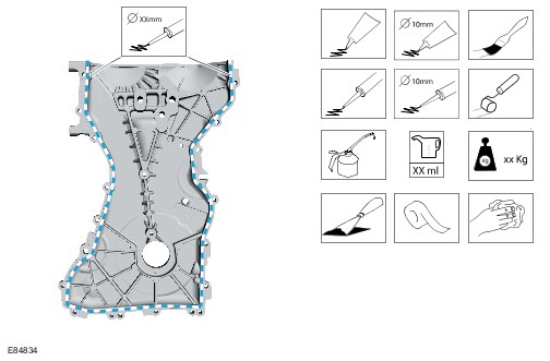
Location symbols are used to show the location of a component or system within the vehicle.
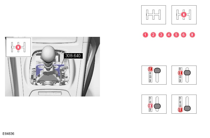
Gearshift lever or selector lever position symbols are used to show which gearshift lever or selector lever position is to be set.
Pointer symbols are used to draw the attention to components and give special instructions such as a required sequence or number of components. The number of components is reflected by the value inside the luty arrow. A sequence number is located inside the circle. Numbers inside circles are also used to allocate special information such as tightening torques or chemicals to a particular component.
Movement arrows are used to show three dimensional or rotational movements. These movements can include specific values inside the symbol if required.
Standard tool symbols recommend the use of certain standard tools. These tools can include dimension values if required.
The following graphic illustrates a set of symbols that are used to provide detailed information on where to apply a material.
Measurement symbols provide detailed information on where to carry out a specific measurement. These symbols can include specific values if required.
Special tools will be shown with the tool number in the illustration. The special tool number(s), general equipment, material(s) and torque figure(s) used for the procedure step will be shown in the text column.
FLUID LEAKS (G2224785)
| SYMPTOM | POSSIBLE CAUSES | ACTION |
|---|---|---|
|
|
|
-
Slight surface oil dampness without drops are acceptable and should not be repaired as a leak
-
Be aware that fluid leaks from above any component may cause oil to collect on the engine and transmission undershield i.e. engine leaks, oil cooler pipe leaks, fuel leaks, coolant leaks
-
Fixing the incorrect leak does not satisfy the customer
- Remove any undershield or engine covers to gain access to the suspected leak area (REFER to: Workshop Manual Section 501-02)
- Using a suitable degreaser, thoroughly degrease the suspected component all the way around as well as, approximately, 25-50mm (1-2 inches) above the suspected leak
- Using a suitable leak detector spray, thoroughly coat the suspected component as well as, approximately, 25-50mm (1-2 inches) above the suspected leak
- Install the transmission/engine undershield and engine covers if removed (REFER to: Workshop Manual Section 501-02)
- Complete a suitable road test and make sure that the engine gets to normal operating temperature
- Remove any undershield or engine covers to gain access to the suspected leak area (REFER to: Workshop Manual Section 501-02)
- Inspect the suspected component for fluid leaks, the detector spray should leave a trace from the leak area
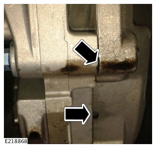
Engine oil leak example graphic. Oil is present between the engine and transmission mating faces, including evidence of oil in the 3 breather holes
- Report or repair the source of the fluid leak
- If no leak is found, continue diagnosis until the exact source of the leak is found
- Install the transmission/engine undershield and engine covers if removed (REFER to: Workshop Manual Section 501-02)
PUBLISHED: 30-NOV-2018
2017.0 RANGE ROVER SPORT (LW), 100-00
GENERAL INFORMATION
SMART KEY TRANSMISSION FREQUENCY (G2325637)
Smart Key Transmission Frequency - 315 MHz
| REGION | RADIO FREQUENCY | ULTRA WIDE BAND RADIO FREQUENCY |
|---|---|---|
| Barbados - 800BC | 315 MHz | 3.9936 GHz |
| Bolivia | 315 MHz | 3.9936 GHz |
| Brazil - 800BH | 315 MHz | 3.9936 GHz |
| Cambodia | 315 MHz | 3.9936 GHz |
| Canada 800CB | 315 MHz | 3.9936 GHz |
| Cayman Islands | 315 MHz | 3.9936 GHz |
| Chile 800CG | 315 MHz | 3.9936 GHz |
| Colombia 800CJ | 315 MHz | 3.9936 GHz |
| Costa Rica 800CM | 315 MHz | 3.9936 GHz |
| Ecuador 800EA | 315 MHz | 3.9936 GHz |
| El Salvador | 315 MHz | 3.9936 GHz |
| Fiji | 315 MHz | 3.9936 GHz |
| Ghana 800GC | 315 MHz | 3.9936 GHz |
| Guam | 315 MHz | 3.9936 GHz |
| Guatemala 800GJ | 315 MHz | 3.9936 GHz |
| Haiti | 315 MHz | 3.9936 GHz |
| Honduras | 315 MHz | 3.9936 GHz |
| Jamaica 800JA | 315 MHz | 3.9936 GHz |
| Japan 800JB | 315 MHz | 3.9936 GHz |
| Malaysia 800MB | 315 MHz | 3.9936 GHz |
| Mexico 800MH | 315 MHz | 3.9936 GHz |
| Nicaragua | 315 MHz | 3.9936 GHz |
| Panama 800PB | 315 MHz | 3.9936 GHz |
| Paraguay 800PD | 315 MHz | 3.9936 GHz |
| Peru 800PE | 315 MHz | 3.9936 GHz |
| Puerto Rico | 315 MHz | 3.9936 GHz |
| Singapore 800MT | 315 MHz | 3.9936 GHz |
| Taiwan 800TB | 315 MHz | 4.4928 GHz |
| Thailand 800TD | 315 MHz | 3.9936 GHz |
| Trinidad & Tobago | 315 MHz | 3.9936 GHz |
| Uruguay 800UC | 315 MHz | 3.9936 GHz |
| USA 800UD | 315 MHz | 3.9936 GHz |
| Vietnam 800VB | 315 MHz | 4.4928 GHz |
| Zambia 800ZB | 315 MHz | 3.9936 GHz |
Smart Key Transmission Frequency - 433.92 MHz
| REGION | RADIO FREQUENCY | ULTRA WIDE BAND RADIO FREQUENCY |
|---|---|---|
| Albania 800AC | 433.92 MHz | 3.9936 GHz |
| Algeria 800AD | 433.92 MHz | 3.9936 GHz |
| Andorra | 433.92 MHz | 3.9936 GHz |
| Angola 800AF | 433.92 MHz | 3.9936 GHz |
| Argentina 800AG | 433.92 MHz | 3.9936 GHz |
| Armenia | 433.92 MHz | 3.9936 GHz |
| Australia 800AJ | 433.92 MHz | 3.9936 GHz |
| Austria 800AK | 433.92 MHz | 3.9936 GHz |
| Azerbaijan 800AZ | 433.92 MHz | 3.9936 GHz |
| Bahrain 800BB | 433.92 MHz | 3.9936 GHz |
| Belarus | 433.92 MHz | 3.9936 GHz |
| Belgium 800BD | 433.92 MHz | 3.9936 GHz |
| Benin | 433.92 MHz | 3.9936 GHz |
| BES Islands (Netherlands Antilles) | 433.92 MHz | 3.9936 GHz |
| Bosnia 800BX | 433.92 MHz | 3.9936 GHz |
| Botswana | 433.92 MHz | 3.9936 GHz |
| Bulgaria 800BN | 433.92 MHz | 3.9936 GHz |
| Cameroon | 433.92 MHz | 3.9936 GHz |
| Canary Islands (Gran Canaria & Tenerife) | 433.92 MHz | 3.9936 GHz |
| Cape Verde | 433.92 MHz | 3.9936 GHz |
| Central African Republic | 433.92 MHz | 3.9936 GHz |
| China 800CH | 433.92 MHz | 4.4928 GHz |
| Croatia 800CP | 433.92 MHz | 3.9936 GHz |
| Curacao (Netherlands Antilles) | 433.92 MHz | 3.9936 GHz |
| Cyprus 800CS | 433.92 MHz | 3.9936 GHz |
| Czech Republic | 433.92 MHz | 3.9936 GHz |
| Denmark 800DB | 433.92 MHz | 3.9936 GHz |
| Dominican Republic 800DD | 433.92 MHz | 3.9936 GHz |
| Egypt 800EB | 433.92 MHz | 3.9936 GHz |
| Estonia | 433.92 MHz | 3.9936 GHz |
| Falkland Islands 800FK | 433.92 MHz | 3.9936 GHz |
| Finland 800FD | 433.92 MHz | 3.9936 GHz |
| France 800FF | 433.92 MHz | 3.9936 GHz |
| Georgia 800GR | 433.92 MHz | 3.9936 GHz |
| Germany 800GK | 433.92 MHz | 3.9936 GHz |
| Gibraltar 800GD | 433.92 MHz | 3.9936 GHz |
| Greece 800GF | 433.92 MHz | 3.9936 GHz |
| Guadeloupe | 433.92 MHz | 3.9936 GHz |
| Hong Kong 800HF | 433.92 MHz | 3.9936 GHz |
| Hungary 800HG | 433.92 MHz | 3.9936 GHz |
| Iceland 800IA | 433.92 MHz | 3.9936 GHz |
| India 800IC | 433.92 MHz | 3.9936 GHz |
| Indonesia 800ID | 433.92 MHz | 3.9936 GHz |
| Iran 800TQ | 433.92 MHz | 3.9936 GHz |
| Iraq 800IF | 433.92 MHz | 3.9936 GHz |
| Ireland 800IG | 433.92 MHz | 3.9936 GHz |
| Israel 800IH | 433.92 MHz | 3.9936 GHz |
| Italy 800IJ | 433.92 MHz | 3.9936 GHz |
| Ivory Coast (Côte d'Ivoire) | 433.92 MHz | 3.9936 GHz |
| Jordan 800JC | 433.92 MHz | 3.9936 GHz |
| Kazakhstan 800KZ | 433.92 MHz | 3.9936 GHz |
| Kenya 800KA | 433.92 MHz | 3.9936 GHz |
| Korea (South) 800KB | 433.92 MHz | 3.9936 GHz |
| Kuwait 800KC | 433.92 MHz | 3.9936 GHz |
| Laos 800LT | 433.92 MHz | 3.9936 GHz |
| Latvia | 433.92 MHz | 3.9936 GHz |
| Lebanon 800LB | 433.92 MHz | 3.9936 GHz |
| Liechtenstein | 433.92 MHz | 3.9936 GHz |
| Lithuania | 433.92 MHz | 3.9936 GHz |
| Luxembourg | 433.92 MHz | 3.9936 GHz |
| Macau | 433.92 MHz | 3.9936 GHz |
| Macedonia 800MY | 433.92 MHz | 3.9936 GHz |
| Malta 800MC | 433.92 MHz | 3.9936 GHz |
| Martinique | 433.92 MHz | 3.9936 GHz |
| Mauritius 800MF | 433.92 MHz | 3.9936 GHz |
| Moldova 800MV | 433.92 MHz | 3.9936 GHz |
| Mongolia 800MZ | 433.92 MHz | 3.9936 GHz |
| Morocco 800MJ | 433.92 MHz | 3.9936 GHz |
| Mozambique | 433.92 MHz | 3.9936 GHz |
| Myanmar (Burma) | 433.92 MHz | 3.9936 GHz |
| Netherlands 800NB | 433.92 MHz | 3.9936 GHz |
| Namibia | 433.92 MHz | 3.9936 GHz |
| New Caledonia 800NG | 433.92 MHz | 3.9936 GHz |
| New Zealand 800NK | 433.92 MHz | 3.9936 GHz |
| Nigeria 800NM | 433.92 MHz | 3.9936 GHz |
| Norway 800NQ | 433.92 MHz | 3.9936 GHz |
| Oman 800MS | 433.92 MHz | 3.9936 GHz |
| Pakistan 800PA | 433.92 MHz | 3.9936 GHz |
| Palestine | 433.92 MHz | 3.9936 GHz |
| Philippines 800PF | 433.92 MHz | 3.9936 GHz |
| Poland 800PG | 433.92 MHz | 3.9936 GHz |
| Portugal 800PH | 433.92 MHz | 3.9936 GHz |
| Qatar 800QA | 433.92 MHz | 3.9936 GHz |
| Reunion | 433.92 MHz | 3.9936 GHz |
| Romania 800RR | 433.92 MHz | 3.9936 GHz |
| Russia 800UE | 433.92 MHz | 3.9936 GHz |
| Saudi Arabia 800SC | 433.92 MHz | 3.9936 GHz |
| Senegal | 433.92 MHz | 3.9936 GHz |
| Serbia 800ER | 433.92 MHz | 3.9936 GHz |
| Sint Maarten | 433.92 MHz | 3.9936 GHz |
| Slovakia 800SW | 433.92 MHz | 3.9936 GHz |
| Slovenia 800SF | 433.92 MHz | 3.9936 GHz |
| South Africa 800SH | 433.92 MHz | 3.9936 GHz |
| Spain 800SK | 433.92 MHz | 3.9936 GHz |
| Sri Lanka 800CF | 433.92 MHz | 3.9936 GHz |
| Suriname | 433.92 MHz | 3.9936 GHz |
| Sweden 800ST | 433.92 MHz | 3.9936 GHz |
| Switzerland 800SU | 433.92 MHz | 3.9936 GHz |
| Tanzania 800TC | 433.92 MHz | 3.9936 GHz |
| Tunisia 800TF | 433.92 MHz | 3.9936 GHz |
| Turkey 800TG | 433.92 MHz | 3.9936 GHz |
| Turks and Caicos Islands | 433.92 MHz | 3.9936 GHz |
| Ukraine 800UK | 433.92 MHz | 3.9936 GHz |
| UAE 800UH | 433.92 MHz | 3.9936 GHz |
| United Kingdom 800UB | 433.92 MHz | 3.9936 GHz |
| Yemen 800YA | 433.92 MHz | 3.9936 GHz |
| Zimbabwe 800SX | 433.92 MHz | 3.9936 GHz |
DIAGNOSTIC TROUBLE CODE INDEX - DTC: ADAPTIVE SPEED CONTROL MODULE (ASCM) (G2016237)
Diagnosis by substitution from a donor vehicle is NOT acceptable. Substitution of control modules does not guarantee confirmation of a fault, and may also cause additional faults in the vehicle being tested and/or the donor vehicle.
-
Guided Diagnostics must be followed and the repair advised by the process completed. Failure to do so may result in the rejection of any warranty claim made.
-
If a control module or a component is suspect and the vehicle remains under manufacturer warranty, refer to the Warranty Policy and Procedures manual, or determine if any prior approval programme is in operation, prior to the installation of a new module/component.
-
Generic scan tools may not read the codes listed, or may read only 5-digit codes. Match the 5 digits from the scan tool to the first 5 digits of the 7-digit code listed to identify the fault (the last 2 digits give extra information read by the manufacturer-approved diagnostic system).
-
When performing voltage or resistance tests, always use a digital multimeter accurate to three decimal places, and with an up-to-date calibration certificate. When testing resistance always take the resistance of the digital multimeter leads into account.
-
Check and rectify basic faults before beginning diagnostic routines involving pinpoint tests.
-
Inspect connectors for signs of water ingress, and pins for damage and/or corrosion.
-
If DTCs are recorded and, after performing the pinpoint tests, a fault is not present, an intermittent concern may be the cause. Always check for loose connections and corroded terminals.
-
Check JLR claims submission system for open campaigns. Refer to the corresponding bulletins and SSMs which may be valid for the specific customer complaint and carry out the recommendations as required.
The table below lists all Diagnostic Trouble Codes (DTCs) that could be logged in the Adaptive Speed Control Module (ASCM). For additional diagnosis and testing information, refer to the relevant Diagnosis and Testing section in the workshop manual. For additional information, refer to:
| DTC | DESCRIPTION | POSSIBLE CAUSES | ACTION |
|---|---|---|---|
| B1A84-81 | Car Configuration Data - Invalid serial data received |
|
|
| C1A67-54 | Forward Looking Sensor - Missing calibration |
|
|
| C1A67-87 | Forward Looking Sensor - Missing message |
|
|
| C1A67-96 | Forward Looking Sensor - Component internal failure |
|
|
| C1A67-97 | Forward Looking Sensor - Component or system operation obstructed or blocked |
NOTE:
Adaptive cruise control is disabled and instrument pack displays warning message "radar sensor blocked"
|
|
| C1A67-98 | Forward Looking Sensor - Component or system over temperature |
|
NOTE:
This DTC may be set by environmental conditions and will clear automatically when conditions allow
|
| U0046-81 | Vehicle Communication Bus C - Invalid serial data received |
|
|
| U0046-82 | Vehicle Communication Bus C - Alive/sequence counter incorrect / not updated |
|
|
| U0046-83 | Vehicle Communication Bus C - Value of signal protection calculation incorrect |
|
|
| U0046-87 | Vehicle Communication Bus C - Missing message |
|
|
| U0046-88 | Vehicle Communication Bus C - Bus off |
|
|
| U0300-00 | Internal Control Module Software Incompatibility - No sub type information |
|
|
| U0300-55 | Internal Control Module Software Incompatibility - Not configured |
|
|
| U0305-4A | Software Incompatibility with Cruise Control Module - Incorrect component installed |
|
|
| U1A00-88 | Private Communication Network - Bus off |
|
|
| U1A14-49 | CAN Initialisation Failure - Internal electronic failure |
|
|
| U1A4B-16 | Control Module Processor B - Circuit voltage below threshold |
|
|
| U2101-00 | Control Module Configuration Incompatible - No sub type information |
|
|
| U2107-00 | Collision Mitigation By Braking - No sub type information |
|
NOTE:
This DTC is for information only
|
| U2108-53 | Adaptive Cruise Control - Deactivated |
|
|
| U2108-67 | Adaptive Cruise Control - Signal incorrect after event |
|
|
| U3000-41 | Control Module - General checksum failure |
|
|
| U3000-42 | Control Module - General memory failure |
|
|
| U3000-44 | Control Module - Data memory failure |
|
|
| U3000-49 | Control Module - Internal electronic failure |
|
|
| U3000-53 | Control Module - Deactivated |
|
|
| U3000-63 | Control Module - Circuit/component protection time-out |
|
|
| U3000-66 | Control Module - Signal has too many transitions / events |
|
|
| U3000-67 | Control Module - Signal incorrect after event |
|
|
| U3000-96 | Control Module - Component internal failure |
|
|
| U3003-16 | Battery Voltage - Circuit voltage below threshold |
|
|
| U3003-17 | Battery Voltage - Circuit voltage above threshold |
|
|
| U3003-62 | Battery Voltage - Signal compare failure |
|
|
DIAGNOSTIC TROUBLE CODE INDEX - DTC: ANTI-LOCK BRAKE SYSTEM CONTROL MODULE (ABS) (G1946623)
Diagnosis by substitution from a donor vehicle is NOT acceptable. Substitution of control modules does not guarantee confirmation of a fault, and may also cause additional faults in the vehicle being tested and/or the donor vehicle.
-
Guided Diagnostics must be followed and the repair advised by the process completed. Failure to do so may result in the rejection of any warranty claim made.
-
If a control module or a component is suspect and the vehicle remains under manufacturer warranty, refer to the Warranty Policy and Procedures manual, or determine if any prior approval programme is in operation, prior to the installation of a new module/component.
-
Generic scan tools may not read the codes listed, or may read only 5-digit codes. Match the 5 digits from the scan tool to the first 5 digits of the 7-digit code listed to identify the fault (the last 2 digits give extra information read by the manufacturer-approved diagnostic system).
-
When performing voltage or resistance tests, always use a digital multimeter that has the resolution ability to view 3 decimal places. For example, on the 2 volts range can measure 1mV or 2 K Ohm range can measure 1 Ohm. When testing resistance always take the resistance of the digital multimeter leads into account.
-
Check and rectify basic faults before beginning diagnostic routines involving pinpoint tests.
-
Inspect connectors for signs of water ingress, and pins for damage and/or corrosion.
-
If DTCs are recorded and, after performing the pinpoint tests, a fault is not present, an intermittent concern may be the cause. Always check for loose connections and corroded terminals.
-
Check JLR claims submission system for open campaigns. Refer to the corresponding bulletins and SSMs which may be valid for the specific customer complaint and carry out the recommendations as required.
-
After clearing the DTCs, the warning indicator(s) may not extinguish until the vehicle speed has exceeded 10 mph (15 km/h). Check whether a vehicle drive cycle is required to validate the repair.
The table below lists all Diagnostic Trouble Codes (DTCs) that could be logged in the Anti-lock Brake System Control Module (ABS). For additional diagnosis and testing information, refer to the relevant Diagnosis and Testing section in the workshop manual. For additional information, refer to:Braking Control System (206-11 Brake Controls, Diagnosis and Testing).
| DTC | DESCRIPTION | POSSIBLE CAUSES | ACTION |
|---|---|---|---|
| B1111-77 | Electric Park Brake Enable - Commanded position not reachable |
NOTE:
This DTC is set when the electric park brake actuators are in known but inconsistent position states. For example, left electric park brake actuator in the applied position and right electric park brake actuator in the releases position.
|
|
| C0001-49 | TCS Control Channel "A" Valve 1 - Internal electronic failure |
|
|
| C0002-49 | TCS Control Channel "A" Valve 2 - Internal electronic failure |
|
|
| C0003-49 | TCS Control Channel "B" Valve 1 - Internal electronic failure |
|
|
| C0004-49 | TCS Control Channel "B" Valve 2 - Internal electronic failure |
|
|
| C0010-49 | Left Front Inlet Control - Internal electronic failure |
|
|
| C0011-49 | Left Front Outlet Control - Internal electronic failure |
|
|
| C0014-49 | Right Front Inlet Control - Internal electronic failure |
|
|
| C0015-49 | Right Front Outlet Control - Internal electronic failure |
|
|
| C0018-49 | Left Rear Inlet Control - Internal electronic failure |
|
|
| C0019-49 | Left Rear Outlet Control - Internal electronic failure |
|
|
| C001A-00 | Left Rear Hydraulic Release Too Long - No sub type information |
|
|
| C001C-49 | Right Rear Inlet Control - Internal electronic failure |
|
|
| C001D-49 | Right Rear Outlet Control - Internal electronic failure |
|
|
| C0020-49 | ABS Pump Motor Control - Internal electronic failure |
|
|
| C0030-38 | Left Front Tone Wheel - Signal frequency incorrect |
|
|
| C0033-38 | Right Front Tone Wheel - Signal frequency incorrect |
|
|
| C0036-38 | Left Rear Tone Wheel - Signal frequency incorrect |
|
|
| C0039-38 | Right Rear Tone Wheel - Signal frequency incorrect |
|
|
| C0040-64 | Brake Pedal Switch "A" - Signal plausibility failure |
|
NOTE:
This DTC may log in conjunction with DTC P0573-64. Check if DTC P0573-64 has been logged by the anti-lock brake system control module and, if the DTC is present, follow the prescribed remedial steps as described in the helptext for DTC P0573-64
|
| C0049-4B | Brake Fluid - Over temperature |
NOTE:
This DTC is for event information only and does not indicate a fault.
|
|
| C0049-68 | Brake Fluid - Event information |
NOTE:
This DTC is for event information only and does not indicate a fault.
|
|
| C0062-81 | Longitudinal Acceleration Sensor - Invalid serial data received |
|
NOTES:
|
| C0063-64 | Yaw Rate Sensor - Signal plausibility failure |
|
NOTE:
The sensor is located inside the restraints control module.
|
| C0063-82 | Yaw Rate Sensor - Alive / Sequence counter incorrect / Not updated |
|
NOTE:
The sensor is located inside the restraints control module.
|
| C0064-64 | Roll Rate Sensor - Signal plausibility failure |
|
NOTE:
The sensor is located inside the restraints control module.
|
| C0069-81 | Yaw Rate/Longitude Sensors - Invalid serial data received |
|
NOTES:
|
| C006A-64 | Multi-axis Acceleration Sensor - Signal plausibility failure |
|
NOTE:
The sensor is located inside the restraints control module.
|
| C006B-00 | Stability System Active Too Long - No sub type information |
|
NOTE:
The yaw rate lateral acceleration sensor is located inside the restraints control module.
|
| C0072-4B | Brake Temperature Too High - Over temperature |
NOTE:
This DTC is for event information only and does not indicate a fault.
|
|
| C0081-00 | ABS Malfunction Indicator - No sub type information |
NOTE:
This DTC may be induced if the vehicle loses traction (skids/spins) whilst the anti-lock brake system is functioning.
|
NOTE:
The yaw rate lateral acceleration sensor is located inside the restraints control module.
|
| C0082-48 | Brake System Malfunction Indicator - Supervision software failure |
|
|
| C0500-14 | Left Front Wheel Speed Sensor Circuit/Open - Circuit short to ground or open |
|
|
| C0501-66 | Left Front Wheel Speed Sensor Range/Performance - Signal has too many transitions/events |
|
|
| C0502-11 | Left Front Wheel Speed Sensor Circuit Low - Circuit short to ground |
|
|
| C0503-12 | Left Front Wheel Speed Sensor Circuit High - Circuit short to battery |
|
|
| C0503-1C | Left Front Wheel Speed Sensor Circuit High - Circuit voltage out of range |
|
|
| C0504-25 | Left Front Wheel Speed Sensor Intermittent/Erratic - Signal shape/waveform failure |
|
|
| C0504-29 | Left Front Wheel Speed Sensor Intermittent/Erratic - Signal invalid |
|
|
| C0504-2F | Left Front Wheel Speed Sensor Intermittent/Erratic - Signal erratic |
NOTE:
This DTC is set when the anti-lock brake system control module detects an implausibly high increase in the wheel speed.
|
|
| C0504-31 | Left Front Wheel Speed Sensor Intermittent/Erratic - No signal |
|
|
| C0504-62 | Left Front Wheel Speed Sensor Intermittent/Erratic - Signal compare failure |
NOTE:
This DTC is set when the anti-lock brake system control module detects an implausible wheel speed.
|
|
| C0504-76 | Left Front Wheel Speed Sensor Intermittent/Erratic - Wrong mounting position |
NOTE:
This DTC is set when the air gap between the wheel speed sensor and the magnetic encoder ring is too great.
|
|
| C0505-76 | Left Front Wheel Speed Sensor Correlation - Wrong mounting position |
NOTE:
This DTC is set when the anti-lock brake system control module detects the wheel rotating in the opposite direction to the other wheels.
|
|
| C0506-14 | Right Front Wheel Speed Sensor Circuit/Open - Circuit short to ground or open |
|
|
| C0507-66 | Right Front Wheel Speed Sensor Range/Performance - Signal has too many transitions/events |
|
|
| C0508-11 | Right Front Wheel Speed Sensor Circuit Low - Circuit short to ground |
|
|
| C0509-12 | Right Front Wheel Speed Sensor Circuit High - Circuit short to battery |
|
|
| C0509-1C | Right Front Wheel Speed Sensor Circuit High - Circuit voltage out of range |
|
|
| C050A-25 | Right Front Wheel Speed Sensor Intermittent/Erratic - Signal shape/waveform failure |
|
|
| C050A-29 | Right Front Wheel Speed Sensor Intermittent/Erratic - Signal invalid |
|
|
| C050A-2F | Right Front Wheel Speed Sensor Intermittent/Erratic - Signal erratic |
NOTE:
This DTC is set when the anti-lock brake system control module detects an implausibly high increase in the wheel speed.
|
|
| C050A-31 | Right Front Wheel Speed Sensor Intermittent/Erratic - No signal |
|
|
| C050A-62 | Right Front Wheel Speed Sensor Intermittent/Erratic - Signal compare failure |
NOTE:
This DTC is set when the anti-lock brake system control module detects an implausible wheel speed.
|
|
| C050A-76 | Right Front Wheel Speed Sensor Intermittent/Erratic - Wrong mounting position |
NOTE:
This DTC is set when the air gap between the wheel speed sensor and the magnetic encoder ring is too great.
|
|
| C050B-76 | Right Front Wheel Speed Sensor Correlation - Wrong mounting position |
NOTE:
This DTC is set when the anti-lock brake system control module detects the wheel rotating in the opposite direction to the other wheels.
|
|
| C050C-14 | Left Rear Wheel Speed Sensor Circuit/Open - Circuit short to ground or open |
|
|
| C050D-66 | Left Rear Wheel Speed Sensor Range/Performance - Signal has too many transitions/events |
|
|
| C050E-11 | Left Rear Wheel Speed Sensor Circuit Low - Circuit short to ground |
|
|
| C050F-12 | Left Rear Wheel Speed Sensor Circuit High - Circuit short to battery |
|
|
| C050F-1C | Left Rear Wheel Speed Sensor Circuit High - Circuit voltage out of range |
|
|
| C0510-25 | Left Rear Wheel Speed Sensor Intermittent/Erratic - Signal shape/waveform failure |
|
|
| C0510-29 | Left Rear Wheel Speed Sensor Intermittent/Erratic - Signal invalid |
|
|
| C0510-2F | Left Rear Wheel Speed Sensor Intermittent/Erratic - Signal erratic |
NOTE:
This DTC is set when the anti-lock brake system control module detects an implausibly high increase in the wheel speed.
|
|
| C0510-31 | Left Rear Wheel Speed Sensor Intermittent/Erratic - No signal |
|
|
| C0510-62 | Left Rear Wheel Speed Sensor Intermittent/Erratic - Signal compare failure |
NOTE:
This DTC is set when the anti-lock brake system control module detects an implausible wheel speed.
|
|
| C0510-76 | Left Rear Wheel Speed Sensor Intermittent/Erratic - Wrong mounting position |
NOTE:
This DTC is set when the air gap between the wheel speed sensor and the magnetic encoder ring is too great.
|
|
| C0511-76 | Left Rear Wheel Speed Sensor Correlation - Wrong mounting position |
NOTE:
This DTC is set when the anti-lock brake system control module detects the wheel rotating in the opposite direction to the other wheels.
|
|
| C0512-14 | Right Rear Wheel Speed Sensor Circuit/Open - Circuit short to ground or open |
|
|
| C0513-66 | Right Rear Wheel Speed Sensor Range/Performance - Signal has too many transitions/events |
|
|
| C0514-11 | Right Rear Wheel Speed Sensor Circuit Low - Circuit short to ground |
|
|
| C0515-12 | Right Rear Wheel Speed Sensor Circuit High - Circuit short to battery |
|
|
| C0515-1C | Right Rear Wheel Speed Sensor Circuit High - Circuit voltage out of range |
|
|
| C0516-25 | Right Rear Wheel Speed Sensor Intermittent/Erratic - Signal shape/waveform failure |
|
|
| C0516-29 | Right Rear Wheel Speed Sensor Intermittent/Erratic - Signal invalid |
|
|
| C0516-2F | Right Rear Wheel Speed Sensor Intermittent/Erratic - Signal erratic |
NOTE:
This DTC is set when the anti-lock brake system control module detects an implausibly high increase in the wheel speed.
|
|
| C0516-31 | Right Rear Wheel Speed Sensor Intermittent/Erratic - No signal |
|
|
| C0516-62 | Right Rear Wheel Speed Sensor Intermittent/Erratic - Signal compare failure |
NOTE:
This DTC is set when the anti-lock brake system control module detects an implausible wheel speed.
|
|
| C0516-76 | Right Rear Wheel Speed Sensor Intermittent/Erratic - Wrong mounting position |
NOTE:
This DTC is set when the air gap between the wheel speed sensor and the magnetic encoder ring is too great.
|
|
| C0517-76 | Right Rear Wheel Speed Sensor Correlation - Wrong mounting position |
NOTE:
This DTC is set when the anti-lock brake system control module detects the wheel rotating in the opposite direction to the other wheels.
|
|
| C051C-64 | Multi-axis Acceleration Sensor Module "A" Range/Performance - Signal plausibility failure |
|
NOTE:
The sensor is located inside the restraints control module.
|
| C0526-81 | Steering Angle Sensor Module - Invalid serial data received |
|
NOTE:
This is not a vehicle harness issue or anti-lock brake system control module issue. The data source module has sent information which it has marked as Invalid
|
| C0528-64 | Steering Angle Sensor Module Range/Performance - Signal plausibility failure |
|
|
| C052A-64 | Steering Angle Sensor Module Correlation - Signal plausibility failure |
NOTE:
This DTC may be induced when a wheel speed sensor is connected to an incorrect wheel speed sensor circuit.
|
|
| C052A-92 | Steering Angle Sensor Module Correlation - Performance or incorrect operation |
|
|
| C052B-49 | ABS Pump Motor Control Range/Performance - Internal electronic failure |
|
|
| C052C-16 | ABS Pump Motor Control Circuit/Open - Circuit voltage below threshold |
|
|
| C0533-14 | Motor Control "A" Circuit Low - Circuit short to ground or open |
NOTES:
|
|
| C0533-16 | Motor Control "A" Circuit Low - Circuit voltage below threshold |
NOTES:
|
|
| C0533-49 | Motor Control "A" Circuit Low - Internal electronic failure |
NOTES:
|
|
| C053B-16 | ABS Valves Supply Voltage Circuit/Open - Circuit voltage below threshold |
NOTES:
|
|
| C053C-49 | Wheel Speed Sensor Generic Range/Performance - Internal electronic failure |
|
|
| C053C-76 | Wheel Speed Sensor Generic Range/Performance - Wrong mounting position |
|
|
| C053D-28 | Brake Pressure Sensor "A" Range/Performance - Signal bias level out of range / zero adjustment failure |
|
|
| C053E-14 | Brake Pressure Sensor "A" Circuit Low - Circuit short to ground or open |
|
|
| C053F-14 | Brake Pressure Sensor "A" Circuit High - Circuit short to ground or open |
|
|
| C0552-29 | Longitudinal Acceleration Sensor Range/Performance - Signal invalid |
|
NOTE:
The sensor is located inside the restraints control module.
|
| C0552-64 | Longitudinal Acceleration Sensor Range/Performance - Signal plausibility failure |
NOTE:
This DTC may be induced by testing the vehicle on chassis dyno rollers.
|
NOTE:
The sensor is located inside the restraints control module.
|
| C0555-4A | Left Front Wheel Speed Sensor Incorrect Component Installed - Incorrect component installed |
|
|
| C0556-4A | Right Front Wheel Speed Sensor Incorrect Component Installed - Incorrect component installed |
|
|
| C0557-4A | Left Rear Wheel Speed Sensor Incorrect Component Installed - Incorrect component installed |
|
|
| C0558-4A | Right Rear Wheel Speed Sensor Incorrect Component Installed - Incorrect component installed |
|
|
| C0563-00 | ABS Control Module Performance - No sub type information |
|
|
| C1015-92 | Vacuum Supply - Performance or incorrect operation |
|
|
| C101A-11 | Vacuum Pressure Sensor - Circuit short to ground |
|
|
| C101A-12 | Vacuum Pressure Sensor - Circuit short to battery |
|
|
| C101A-1C | Vacuum Pressure Sensor - Circuit voltage out of range |
|
|
| C101A-64 | Vacuum Pressure Sensor - Signal plausibility failure |
|
|
| C101A-81 | Vacuum Pressure Sensor - Invalid serial data received |
|
|
| C101A-86 | Vacuum Pressure Sensor - Signal invalid |
|
|
| C1054-68 | System Functionality Reduced By Diagnostic Request - Event information |
NOTE:
This DTC is for event information only and does not indicate a fault.
|
|
| C105C-68 | ABS Dynomometer Test Mode Active - Event information |
NOTES:
|
|
| C1067-24 | All Terrain / Road Progress Control Switch - Signal stuck high |
|
NOTE:
This DTC may be induced by the driver operating the all terrain progress control switch for longer than 60 seconds.
|
| C1109-24 | Vehicle Dynamics Control Switch - Signal stuck high |
NOTE:
This DTC may be induced by the driver operating the dynamic stability control switch for longer than 60 seconds.
|
|
| C1A43-16 | Motor Supply - Circuit voltage below threshold |
NOTE:
This DTC is set if the electric park brake is operated when the voltage at the anti-lock brake system control module is less than 9.0V for 1.6 seconds. Or while the park brake is actuating the voltage falls below 8.0V for 1.6 seconds.
|
|
| C1A43-17 | Motor Supply - Circuit voltage above threshold |
NOTE:
This DTC is set if the electric park brake is operated when the voltage at the anti-lock brake system control module is greater than 16.50V.
|
|
| C1A8A-95 | Wheel Speed Sensor Signals Swapped Front Axle - Incorrect assembly |
|
|
| C1A8B-95 | Wheel Speed Sensor Signals Swapped Rear Axle - Incorrect assembly |
|
|
| C1A8C-64 | Wheel Speed Sensor Supply Circuit - Signal plausibility failure |
|
|
| C1A8D-64 | Wheel Speed Sensor Supply Circuit Low - Signal plausibility failure |
|
|
| C1A8E-12 | Wheel Speed Sensor Supply Circuit High - Circuit short to battery |
|
|
| C1B22-24 | Hill Descent Switch - Signal stuck high |
NOTE:
This DTC may be induced by the driver operating the hill descent control switch for longer than 60 seconds.
|
|
| C2005-07 | Right Actuator - Mechanical failures |
|
|
| C2005-71 | Right Actuator - Actuator stuck |
|
NOTE:
Do NOT install a new ABS control module as this will NOT rectify the fault
|
| C2005-77 | Right Actuator - Commanded position not reachable |
|
|
| C2006-07 | Left Actuator - Mechanical failures |
|
|
| C2006-71 | Left Actuator - Actuator stuck |
|
NOTE:
Do NOT install a new ABS control module as this will NOT rectify the fault
|
| C2006-77 | Left Actuator - Commanded position not reachable |
|
|
| C2007-01 | Right Motor - General electrical failure |
|
|
| C2007-11 | Right Motor - Circuit short to ground |
|
|
| C2007-12 | Right Motor - Circuit short to battery |
|
|
| C2007-13 | Right Motor - Circuit open |
|
|
| C2007-19 | Right Motor - Circuit current above threshold |
|
|
| C2007-1E | Right Motor - Circuit resistance out of range |
|
|
| C2007-72 | Right Motor - Actuator stuck open |
|
|
| C2007-73 | Right Motor - Actuator stuck closed |
|
|
| C2008-01 | Left Motor - General electrical failure |
|
|
| C2008-11 | Left Motor - Circuit short to ground |
|
|
| C2008-12 | Left Motor - Circuit short to battery |
|
|
| C2008-13 | Left Motor - Circuit open |
|
|
| C2008-16 | Left Motor - Circuit voltage below threshold |
|
|
| C2008-19 | Left Motor - Circuit current above threshold |
|
|
| C2008-1E | Left Motor - Circuit resistance out of range |
|
|
| C2008-72 | Left Motor - Actuator stuck open |
|
|
| C2008-73 | Left Motor - Actuator stuck closed |
|
|
| P0040-1A | O2 Sensor Signals Swapped Bank 1 Sensor 1 Bank 2 Sensor 1 - Circuit resistance below threshold |
NOTE:
Please ignore DTC description, this is NOT an oxygen sensor fault
|
|
| P0120-81 | Throttle/Pedal Position Sensor A Circuit - Invalid serial data received |
|
NOTE:
This is not a vehicle harness issue or anti-lock brake system control module issue. The data source module has sent information which it has marked as invalid
|
| P0573-64 | Brake Switch "A" Circuit High - Signal plausibility failure |
|
NOTE:
This DTC will log if the brake pedal switch is continuously active for 45 seconds or more while the vehicle speed is 17 km/h or greater and throttle application is at 5% or higher. If all these conditions continue, the Dynamic Stability Control (DSC) warning indicator will illuminate, under some conditions further warning indicators may be activated and a warning message may appear in the message centre. This DTC may log in conjunction with DTC C0040-64
|
| P0601-49 | Internal Control Module Memory Checksum Error - Internal electronic failure |
|
|
| P0602-46 | Control Module Programming Error - Calibration/parameter memory failure |
|
|
| P0602-49 | Control Module Programming Error - Internal electronic failure |
|
|
| P0604-49 | Internal Control Module Random Access Memory (RAM) Error - Internal electronic failure |
|
|
| P0605-46 | Internal Control Module Read Only Memory (ROM) Error - Calibration/parameter memory failure |
|
|
| P0605-49 | Internal Control Module Read Only Memory (ROM) Error - Internal electronic failure |
|
|
| P0605-51 | Internal Control Module Read Only Memory (ROM) Error - Not programmed |
|
|
| P0606-49 | Control Module Processor - Internal electronic failure |
|
|
| P0607-49 | Control Module Performance - Internal electronic failure |
|
|
| P060A-48 | Internal Control Module Monitoring Processor Performance - Supervision software failure |
|
|
| P060B-49 | Internal Control Module A/D Processing Performance - Internal electronic failure |
|
|
| P060C-49 | Internal Control Module Main Processor Performance - Internal electronic failure |
|
|
| P062F-48 | Internal Control Module EEPROM Error - Supervision software failure |
|
|
| P0634-4B | Control Module Internal Temperature "A" Too High - Over temperature |
NOTES:
|
|
| P064F-55 | Unauthorized Software/Calibration Detected - Not configured |
|
|
| P16A1-49 | ABS Valve Drive Fault - Internal electronic failure |
|
|
| P16A2-16 | ABS Internal Control Module Monitor Performance - Circuit voltage below threshold |
|
|
| P16A2-49 | ABS Internal Control Module Monitor Performance - Internal electronic failure |
|
|
| P1719-81 | Engine Torque Signal - Invalid serial data received |
|
NOTE:
This is not a vehicle harness issue or anti-lock brake system control module issue. The data source module has sent information which it has marked as Invalid
|
| P1719-82 | Engine Torque Signal - Alive/sequence counter incorrect / not updated |
|
NOTE:
This is not a vehicle harness issue or anti-lock brake system control module issue. The data source module has not performed a calculation correctly
|
| P1719-83 | Engine Torque Signal - Value of signal protection calculation incorrect |
|
NOTE:
This is not a vehicle harness issue or anti-lock brake system control module issue. The data source module has not performed a calculation correctly
|
| U0046-81 | Vehicle Communication Bus C - Invalid serial data received |
|
NOTE:
This is not a vehicle harness issue or anti-lock brake system control module issue. The data source module has sent information which it has marked as Invalid
|
| U0046-82 | Vehicle Communication Bus C - Alive/sequence counter incorrect / not updated |
|
NOTE:
This is not a vehicle harness issue or anti-lock brake system control module issue. The data source module has not performed a calculation correctly
|
| U0046-83 | Vehicle Communication Bus C - Value of signal protection calculation incorrect |
|
NOTE:
This is not a vehicle harness issue or anti-lock brake system control module issue. The data source module has not performed a calculation correctly
|
| U0046-87 | Vehicle Communication Bus C - Missing message |
|
|
| U0075-88 | Control Module Communication Bus "C" Off - Bus off |
|
|
| U0078-88 | Control Module Communication Bus "F" Off - Bus off |
|
NOTE:
The FlexRay wiring harness must not be repaired by making a localised wiring repair. A new wiring harness should be installed.
|
| U0080-81 | Vehicle Communication Bus F - Invalid serial data received |
|
NOTE:
This is not a vehicle harness issue or anti-lock brake system control module issue. The data source module has sent information which it has marked as Invalid
|
| U0080-82 | Vehicle Communication Bus F - Alive/sequence counter incorrect / not updated |
|
NOTE:
This is not a vehicle harness issue or anti-lock brake system control module issue. The data source module has not performed a calculation correctly
|
| U0080-83 | Vehicle Communication Bus F - Value of signal protection calculation incorrect |
|
NOTE:
This is not a vehicle harness issue or anti-lock brake system control module issue. The data source module has not performed a calculation correctly
|
| U0080-87 | Vehicle Communication Bus F - Missing message |
|
NOTE:
The FlexRay wiring harness must not be repaired by making a localised wiring repair. A new wiring harness should be installed.
|
| U0100-87 | Lost Communication With ECM/PCM "A" - Missing message |
|
NOTE:
The FlexRay wiring harness must not be repaired by making a localised wiring repair. A new wiring harness should be installed.
|
| U0101-87 | Lost Communication With TCM - Missing message |
|
NOTE:
The FlexRay wiring harness must not be repaired by making a localised wiring repair. A new wiring harness should be installed.
|
| U0102-87 | Lost Communication With Transfer Case Control Module - Missing message |
|
NOTE:
The FlexRay wiring harness must not be repaired by making a localised wiring repair. A new wiring harness should be installed.
|
| U0115-87 | Lost Communication With ECM/PCM "B" - Missing message |
|
NOTE:
The FlexRay wiring harness must not be repaired by making a localised wiring repair. A new wiring harness should be installed.
|
| U0123-81 | Lost Communication With Yaw Rate Sensor Module - Invalid serial data received |
|
NOTE:
The sensor is located inside the restraints control module.
|
| U0123-87 | Lost Communication With Yaw Rate Sensor Module - Missing message |
|
NOTE:
The sensor is located inside the restraints control module.
|
| U0125-81 | Lost Communication With Multi-axis Acceleration Sensor Module - Invalid serial data received |
|
NOTE:
The sensor is located inside the restraints control module.
|
| U0125-87 | Lost Communication With Multi-axis Acceleration Sensor Module - Missing message |
|
NOTE:
The sensor is located inside the restraints control module.
|
| U0126-82 | Lost Communication With Steering Angle Sensor Module - Alive/sequence counter incorrect / not updated |
|
NOTE:
This is not a vehicle harness issue or anti-lock brake system control module issue. The data source module has not performed a calculation correctly
|
| U0126-87 | Lost Communication With Steering Angle Sensor Module - Missing message |
|
|
| U012A-87 | Lost Communication With Chassis Control Module "A" - Missing message |
|
|
| U0140-87 | Lost Communication With Body Control Module - Missing message |
|
|
| U0148-87 | Lost Communication With Gateway "C" - Missing message |
|
|
| U0291-87 | Lost Communication With Gear Shift Control Module "B" - Missing message |
|
|
| U0401-81 | Invalid Data Received From ECM/PCM "A" - Invalid serial data received |
|
NOTE:
This is not a vehicle harness issue or anti-lock brake system control module issue. The data source module has sent information which it has marked as Invalid
|
| U0402-81 | Invalid Data Received From TCM - Invalid serial data received |
|
NOTE:
This is not a vehicle harness issue or anti-lock brake system control module issue. The data source module has sent information which it has marked as Invalid
|
| U0402-82 | Invalid Data Received From TCM - Alive/sequence counter incorrect / not updated |
|
NOTE:
This is not a vehicle harness issue or anti-lock brake system control module issue. The data source module has not performed a calculation correctly
|
| U0402-83 | Invalid Data Received From TCM - Value of signal protection calculation incorrect |
|
NOTE:
This is not a vehicle harness issue or anti-lock brake system control module issue. The data source module has not performed a calculation correctly
|
| U0405-68 | Invalid Data Received From Cruise Control Module - Event information |
|
|
| U0414-81 | Invalid Data Received From Four-Wheel Drive Clutch Control Module - Invalid serial data received |
|
NOTE:
This is not a vehicle harness issue or anti-lock brake system control module issue. The data source module has sent information which it has marked as Invalid
|
| U0414-82 | Invalid Data Received From Four-Wheel Drive Clutch Control Module - Alive/sequence counter incorrect / not updated |
|
|
| U0414-83 | Invalid Data Received From Four-Wheel Drive Clutch Control Module - Value of signal protection calculation incorrect |
|
NOTE:
This is not a vehicle harness issue or anti-lock brake system control module issue. The data source module has not performed a calculation correctly
|
| U0428-81 | Invalid Data Received From Steering Angle Sensor Module - Invalid serial data received |
|
NOTE:
This is not a vehicle harness issue or anti-lock brake system control module issue. The data source module has sent information which it has marked as Invalid
|
| U0428-83 | Invalid Data Received From Steering Angle Sensor Module - Value of signal protection calculation incorrect |
|
NOTE:
This is not a vehicle harness issue or anti-lock brake system control module issue. The data source module has not performed a calculation correctly
|
| U042B-81 | Invalid Data Received From Chassis Control Module "A" - Invalid serial data received |
|
NOTE:
This is not a vehicle harness issue or anti-lock brake system control module issue. The data source module has sent information which it has marked as Invalid
|
| U0432-82 | Invalid Data Received From Multi-axis Acceleration Sensor Module - Alive/sequence counter incorrect / not updated |
|
NOTE:
This is not a vehicle harness issue or anti-lock brake system control module issue. The data source module has not performed a calculation correctly
|
| U0432-83 | Invalid Data Received From Multi-axis Acceleration Sensor Module - Value of signal protection calculation incorrect |
|
NOTE:
This is not a vehicle harness issue or anti-lock brake system control module issue. The data source module has not performed a calculation correctly
|
| U0437-81 | Invalid Data Received From Differential Control Module - Rear - Invalid serial data received |
|
NOTE:
This is not a vehicle harness issue or anti-lock brake system control module issue. The data source module has sent information which it has marked as Invalid
|
| U0442-81 | Invalid Data Received From ECM/PCM "B" - Invalid serial data received |
|
NOTE:
This is not a vehicle harness issue or anti-lock brake system control module issue. The data source module has sent information which it has marked as Invalid
|
| U0447-54 | Invalid Data Received From Gateway "A" - Missing calibration |
|
NOTE:
After updating the car configuration file, set the ignition to on and wait 30 seconds before clearing the DTCs.
|
| U0449-81 | Invalid Data Received From Gateway "C" - Invalid serial data received |
|
NOTE:
This is not a vehicle harness issue or anti-lock brake system control module issue. The data source module has sent information which it has marked as Invalid
|
| U0449-82 | Invalid Data Received From Gateway "C" - Alive/sequence counter incorrect / not updated |
|
NOTE:
This is not a vehicle harness issue or anti-lock brake system control module issue. The data source module has not performed a calculation correctly
|
| U0449-83 | Invalid Data Received From Gateway "C" - Value of signal protection calculation incorrect |
|
NOTE:
This is not a vehicle harness issue or anti-lock brake system control module issue. The data source module has not performed a calculation correctly
|
| U0513-82 | Invalid Data Received From Yaw Rate Sensor Module - Alive/sequence counter incorrect / not updated |
|
NOTES:
|
| U0513-83 | Invalid Data Received From Yaw Rate Sensor Module - Value of signal protection calculation incorrect |
|
NOTES:
|
| U0536-81 | Invalid Data Received From Lateral Acceleration Sensor Module - Invalid serial data received |
|
NOTE:
This is not a vehicle harness issue or anti-lock brake system control module issue. The data source module has sent information which it has marked as Invalid
|
| U0592-81 | Invalid Data Received From Gear Shift Control Module "B" - Invalid serial data received |
|
NOTE:
This is not a vehicle harness issue or anti-lock brake system control module issue. The data source module has sent information which it has marked as Invalid
|
| U0595-82 | Invalid Data Received From Powertrain Control Monitor Module - Alive/sequence counter incorrect / not updated |
|
NOTE:
This is not a vehicle harness issue or anti-lock brake system control module issue. The data source module has not performed a calculation correctly
|
| U0595-83 | Invalid Data Received From Powertrain Control Monitor Module - Value of signal protection calculation incorrect |
|
NOTE:
This is not a vehicle harness issue or anti-lock brake system control module issue. The data source module has not performed a calculation correctly
|
| U101C-87 | Lost Communication with PCM Node D - Missing message |
|
|
| U101D-87 | Lost Communication with PCM Node E - Missing message |
|
|
| U101E-81 | Lost Communication with PCM Node J - Invalid serial data received |
|
NOTE:
This is not a vehicle harness issue or anti-lock brake system control module issue. The data source module has sent information which it has marked as Invalid
|
| U101E-87 | Lost Communication with PCM Node J - Missing message |
|
|
| U1020-81 | Lost Communication with PCM Node P - Invalid serial data received |
|
NOTE:
This is not a vehicle harness issue or anti-lock brake system control module issue. The data source module has sent information which it has marked as Invalid
|
| U1020-87 | Lost Communication with PCM Node P - Missing message |
|
|
| U1100-49 | Control Module Internal Flexray Hardware - Internal electronic failure |
|
|
| U1101-49 | Control Module Internal CAN Hardware - Internal electronic failure |
|
|
| U1A4C-00 | Build / End of Line Mode Active - No sub type information |
NOTES:
|
|
| U1A4C-68 | Build / End of Line Mode Active - Event information |
NOTES:
|
|
| U2002-13 | Switch - Circuit open |
|
NOTE:
To validate the repair, cycle the ignition or with the ignition set to on apply and release the electric park brake
|
| U2002-2A | Switch - Signal stuck in range |
NOTE:
This DTC may be induced by the driver operating the electric park brake switch for longer than 2.5 minutes.
|
|
| U2002-92 | Switch - Performance or incorrect operation |
NOTE:
This DTC may be induced by the driver operating the electric park brake switch rapidly
|
|
| U2012-00 | Car Configuration Parameter(s) - No sub type information |
NOTE:
This DTC may be set if different wheels and tires have been installed but the car configuration file has not been updated.
|
NOTE:
After updating the car configuration file, set the ignition to on and wait 30 seconds before clearing the DTCs.
|
| U2100-54 | Initial Configuration Not Complete - Missing calibration |
NOTE:
The park brake yellow warning indicator will also be illuminated
|
|
| U2101-55 | Control Module Configuration Incompatible - Not configured |
|
|
| U3000-04 | Control Module - System internal failures |
|
|
| U3000-44 | Control Module - Data memory failure |
|
|
| U3000-46 | Control Module - Calibration/parameter memory failure |
|
|
| U3000-48 | Control Module - Supervision software failure |
|
|
| U3000-49 | Control Module - Internal electronic failure |
|
|
| U3000-4B | Control Module - Over temperature |
NOTE:
This DTC may be induced by Using the Jaguar Land Rover approved diagnostic equipment to operate the hydraulic control unit for a prolonged period.
|
|
| U3000-57 | Control Module - Invalid/incomplete software component |
|
|
| U3000-92 | Control Module - Performance or incorrect operation |
|
|
| U3001-44 | Control Module Improper Shutdown - Data memory failure |
|
|
| U3001-77 | Control Module Improper Shutdown - Commanded position not reachable |
NOTE:
The park brake yellow warning indicator will also be illuminated
|
NOTE:
Release the electric park brake, so the park brakes are in a known state
|
DIAGNOSTIC TROUBLE CODE INDEX - DTC: AUDIO AMPLIFIER MODULE (AAM) (G2016303)
Diagnosis by substitution from a donor vehicle is NOT acceptable. Substitution of control modules does not guarantee confirmation of a fault, and may also cause additional faults in the vehicle being tested and/or the donor vehicle.
-
Guided Diagnostics must be followed and the repair advised by the process completed. Failure to do so may result in the rejection of any warranty claim made.
-
If a control module or a component is suspect and the vehicle remains under manufacturer warranty, refer to the Warranty Policy and Procedures manual, or determine if any prior approval programme is in operation, prior to the installation of a new module/component.
-
Generic scan tools may not read the codes listed, or may read only 5-digit codes. Match the 5 digits from the scan tool to the first 5 digits of the 7-digit code listed to identify the fault (the last 2 digits give extra information read by the manufacturer-approved diagnostic system).
-
When performing voltage or resistance tests, always use a digital multimeter accurate to three decimal places, and with an up-to-date calibration certificate. When testing resistance always take the resistance of the digital multimeter leads into account.
-
Check and rectify basic faults before beginning diagnostic routines involving pinpoint tests.
-
Inspect connectors for signs of water ingress, and pins for damage and/or corrosion.
-
If DTCs are recorded and, after performing the pinpoint tests, a fault is not present, an intermittent concern may be the cause. Always check for loose connections and corroded terminals.
-
Check JLR claims submission system for open campaigns. Refer to the corresponding bulletins and SSMs which may be valid for the specific customer complaint and carry out the recommendations as required.
The table below lists all Diagnostic Trouble Codes (DTCs) that could be logged in the Audio Amplifier Module (AAM). For additional diagnosis and testing information, refer to the relevant Diagnosis and Testing section in the workshop manual. For additional information, refer to:Information and Entertainment System (415-01 Information and Entertainment System - Vehicles With: InControl Touch Pro, Diagnosis and Testing).
| DTC | DESCRIPTION | POSSIBLE CAUSES | ACTION |
|---|---|---|---|
| B128A-11 | Speaker #13 - Circuit short to ground |
NOTE:
Circuit reference - LH_SURR_POS/LH_SURR_NEG
|
NOTE:
Meridian® Surround and Meridian® Reference audio system only
|
| B128A-12 | Speaker #13 - Circuit short to battery |
NOTE:
Circuit reference - LH_SURR_POS/LH_SURR_NEG
|
NOTE:
Meridian® Surround and Meridian® Reference audio system only
|
| B128A-13 | Speaker #13 - Circuit open |
NOTE:
Circuit reference - LH_SURR_POS/LH_SURR_NEG
|
NOTE:
Meridian® Surround and Meridian® Reference audio system only
|
| B128A-1A | Speaker #13 - Circuit resistance below threshold |
NOTE:
Circuit reference - LH_SURR_POS/LH_SURR_NEG
|
NOTE:
Meridian® Surround and Meridian® Reference audio system only
|
| B128A-4A | Speaker #13 - Incorrect component installed |
NOTE:
Circuit reference - LH_SURR_POS/LH_SURR_NEG
|
NOTE:
Meridian® Surround and Meridian® Reference audio system only
|
| B128B-11 | Speaker #14 - Circuit short to ground |
|
NOTE:
Meridian® Surround and Meridian® Reference audio system only
|
| B128B-12 | Speaker #14 - Circuit short to battery |
|
NOTE:
Meridian® Surround and Meridian® Reference audio system only
|
| B128B-13 | Speaker #14 - Circuit open |
|
NOTE:
Meridian® Surround and Meridian® Reference audio system only
|
| B128B-1A | Speaker #14 - Circuit resistance below threshold |
|
NOTE:
Meridian® Surround and Meridian® Reference audio system only
|
| B128B-4A | Speaker #14 - Incorrect component installed |
|
NOTE:
Meridian® Surround and Meridian® Reference audio system only
|
| B128C-11 | Speaker #15 - Circuit short to ground |
NOTE:
Circuit reference - FRONT CENTRE MID POS/FRONT CENTRE MID NEG
|
NOTE:
Meridian® Surround and Meridian® Reference audio system only
|
| B128C-12 | Speaker #15 - Circuit short to battery |
NOTE:
Circuit reference - FRONT CENTRE MID POS/FRONT CENTRE MID NEG
|
NOTE:
Meridian® Surround and Meridian® Reference audio system only
|
| B128C-13 | Speaker #15 - Circuit open |
NOTE:
Circuit reference - FRONT CENTRE MID POS/FRONT CENTRE MID NEG
|
NOTE:
Meridian® Surround and Meridian® Reference audio system only
|
| B128C-1A | Speaker #15 - Circuit resistance below threshold |
NOTE:
Circuit reference - FRONT CENTRE MID POS/FRONT CENTRE MID NEG
|
NOTE:
Meridian® Surround and Meridian® Reference audio system only
|
| B128C-4A | Speaker #15 - Incorrect component installed |
NOTE:
Circuit reference - FRONT CENTRE MID POS/FRONT CENTRE MID NEG
|
NOTE:
Meridian® Surround and Meridian® Reference audio system only
|
| B128D-11 | Speaker #16 - Circuit short to ground |
NOTE:
Circuit reference - FRONT CENTRE HIGH POS/FRONT CENTRE HIGH NEG
|
NOTE:
Meridian® Surround and Meridian® Reference audio system only
|
| B128D-12 | Speaker #16 - Circuit short to battery |
NOTE:
Circuit reference - FRONT CENTRE HIGH POS/FRONT CENTRE HIGH NEG
|
NOTE:
Meridian® Surround and Meridian® Reference audio system only
|
| B128D-13 | Speaker #16 - Circuit open |
NOTE:
Circuit reference - FRONT CENTRE HIGH POS/FRONT CENTRE HIGH NEG
|
NOTE:
Meridian® Surround and Meridian® Reference audio system only
|
| B128D-1A | Speaker #16 - Circuit resistance below threshold |
NOTE:
Circuit reference - FRONT CENTRE HIGH POS/FRONT CENTRE HIGH NEG
|
NOTE:
Meridian® Surround and Meridian® Reference audio system only
|
| B128D-4A | Speaker #16 - Incorrect component installed |
NOTE:
Circuit reference - FRONT CENTRE HIGH POS/FRONT CENTRE HIGH NEG
|
NOTE:
Meridian® Surround and Meridian® Reference audio system only
|
| B128E-11 | Speaker #17 - Circuit short to ground |
NOTE:
Circuit reference - FL_SEAT_BACK_POS/RL_MID_POS FL_SEAT_BACK_NEG/RL_MID_NEG
|
NOTE:
Meridian® Reference audio system only
|
| B128E-12 | Speaker #17 - Circuit short to battery |
NOTE:
Circuit reference - FL_SEAT_BACK_POS/RL_MID_POS FL_SEAT_BACK_NEG/RL_MID_NEG
|
NOTE:
Meridian® Reference audio system only
|
| B128E-13 | Speaker #17 - Circuit open |
NOTE:
Circuit reference - FL_SEAT_BACK_POS/RL_MID_POS FL_SEAT_BACK_NEG/RL_MID_NEG
|
NOTE:
Meridian® Reference audio system only
|
| B128E-1A | Speaker #17 - Circuit resistance below threshold |
NOTE:
Circuit reference - FL_SEAT_BACK_POS/RL_MID_POS FL_SEAT_BACK_NEG/RL_MID_NEG
|
NOTE:
Meridian® Reference audio system only
|
| B128E-4A | Speaker #17 - Incorrect component installed |
NOTE:
Circuit reference - FL_SEAT_BACK_POS/RL_MID_POS FL_SEAT_BACK_NEG/RL_MID_NEG
|
NOTE:
Meridian® Reference audio system only
|
| B128F-11 | Speaker #18 - Circuit short to ground |
NOTE:
Circuit reference - FR_SEAT_BACK_POS/RR_MID_POS FR_SEAT_BACK_NEG/RR_MID_NEG
|
NOTE:
Meridian® Reference audio system only
|
| B128F-12 | Speaker #18 - Circuit short to battery |
NOTE:
Circuit reference - FR_SEAT_BACK_POS/RR_MID_POS FR_SEAT_BACK_NEG/RR_MID_NEG
|
NOTE:
Meridian® Reference audio system only
|
| B128F-13 | Speaker #18 - Circuit open |
NOTE:
Circuit reference - FR_SEAT_BACK_POS/RR_MID_POS FR_SEAT_BACK_NEG/RR_MID_NEG
|
NOTE:
Meridian® Reference audio system only
|
| B128F-1A | Speaker #18 - Circuit resistance below threshold |
NOTE:
Circuit reference - FR_SEAT_BACK_POS/RR_MID_POS FR_SEAT_BACK_NEG/RR_MID_NEG
|
NOTE:
Meridian® Reference audio system only
|
| B128F-4A | Speaker #18 - Incorrect component installed |
NOTE:
Circuit reference - FR_SEAT_BACK_POS/RR_MID_POS FR_SEAT_BACK_NEG/RR_MID_NEG
|
NOTE:
Meridian® Reference audio system only
|
| B1290-11 | Speaker #19 - Circuit short to ground |
NOTE:
Circuit reference - LEFT_REAR_HIGH_POS/LEFT_REAR_HIGH_NEG
|
NOTE:
Meridian® Reference audio system only
|
| B1290-12 | Speaker #19 - Circuit short to battery |
NOTE:
Circuit reference - LEFT_REAR_HIGH_POS/LEFT_REAR_HIGH_NEG
|
NOTE:
Meridian® Reference audio system only
|
| B1290-13 | Speaker #19 - Circuit open |
NOTE:
Circuit reference - LEFT_REAR_HIGH_POS/LEFT_REAR_HIGH_NEG
|
NOTE:
Meridian® Reference audio system only
|
| B1290-1A | Speaker #19 - Circuit resistance below threshold |
NOTE:
Circuit reference - LEFT_REAR_HIGH_POS/LEFT_REAR_HIGH_NEG
|
NOTE:
Meridian® Reference audio system only
|
| B1290-4A | Speaker #19 - Incorrect component installed |
NOTE:
Circuit reference - LEFT_REAR_HIGH_POS/LEFT_REAR_HIGH_NEG
|
NOTE:
Meridian® Reference audio system only
|
| B1291-11 | Speaker #20 - Circuit short to ground |
NOTE:
Circuit reference - RIGHT_REAR_HIGH_POS/RIGHT_REAR_HIGH_NEG
|
NOTE:
Meridian® Reference audio system only
|
| B1291-12 | Speaker #20 - Circuit short to battery |
NOTE:
Circuit reference - RIGHT_REAR_HIGH_POS/RIGHT_REAR_HIGH_NEG
|
NOTE:
Meridian® Reference audio system only
|
| B1291-13 | Speaker #20 - Circuit open |
NOTE:
Circuit reference - RIGHT_REAR_HIGH_POS/RIGHT_REAR_HIGH_NEG
|
NOTE:
Meridian® Reference audio system only
|
| B1291-1A | Speaker #20 - Circuit resistance below threshold |
NOTE:
Circuit reference - RIGHT_REAR_HIGH_POS/RIGHT_REAR_HIGH_NEG
|
NOTE:
Meridian® Reference audio system only
|
| B1291-4A | Speaker #20 - Incorrect component installed |
NOTE:
Circuit reference - RIGHT_REAR_HIGH_POS/RIGHT_REAR_HIGH_NEG
|
NOTE:
Meridian® Reference audio system only
|
| B1292-11 | Speaker #21 - Circuit short to ground |
NOTE:
Circuit reference - FRONT_LEFT_HEADLINING_POS/FRONT_LEFT_HEADLINING_NEG
|
NOTE:
Meridian® Reference audio system only
|
| B1292-12 | Speaker #21 - Circuit short to battery |
NOTE:
Circuit reference - FRONT_LEFT_HEADLINING_POS/FRONT_LEFT_HEADLINING_NEG
|
NOTE:
Meridian® Reference audio system only
|
| B1292-13 | Speaker #21 - Circuit open |
NOTE:
Circuit reference - FRONT_LEFT_HEADLINING_POS/FRONT_LEFT_HEADLINING_NEG
|
NOTE:
Meridian® Reference audio system only
|
| B1292-1A | Speaker #21 - Circuit resistance below threshold |
NOTE:
Circuit reference - FRONT_LEFT_HEADLINING_POS/FRONT_LEFT_HEADLINING_NEG
|
NOTE:
Meridian® Reference audio system only
|
| B1292-4A | Speaker #21 - Incorrect component installed |
NOTE:
Circuit reference - FRONT_LEFT_HEADLINING_POS/FRONT_LEFT_HEADLINING_NEG
|
NOTE:
Meridian® Reference audio system only
|
| B1293-11 | Speaker #22 - Circuit short to ground |
NOTE:
Circuit reference - FRONT_RIGHT_HEADLINING_POS/FRONT_RIGHT_HEADLINING_NEG
|
NOTE:
Meridian® Reference audio system only
|
| B1293-12 | Speaker #22 - Circuit short to battery |
NOTE:
Circuit reference - FRONT_RIGHT_HEADLINING_POS/FRONT_RIGHT_HEADLINING_NEG
|
NOTE:
Meridian® Reference audio system only
|
| B1293-13 | Speaker #22 - Circuit open |
NOTE:
Circuit reference - FRONT_RIGHT_HEADLINING_POS/FRONT_RIGHT_HEADLINING_NEG
|
NOTE:
Meridian® Reference audio system only
|
| B1293-1A | Speaker #22 - Circuit resistance below threshold |
NOTE:
Circuit reference - FRONT_RIGHT_HEADLINING_POS/FRONT_RIGHT_HEADLINING_NEG
|
NOTE:
Meridian® Reference audio system only
|
| B1293-4A | Speaker #22 - Incorrect component installed |
NOTE:
Circuit reference - FRONT_RIGHT_HEADLINING_POS/FRONT_RIGHT_HEADLINING_NEG
|
NOTE:
Meridian® Reference audio system only
|
| B1294-11 | Speaker #23 - Circuit short to ground |
NOTE:
Circuit reference - REAR_LEFT_HEADLINING_POS/REAR_LEFT_HEADLINING_NEG
|
NOTE:
Meridian® Reference audio system only
|
| B1294-12 | Speaker #23 - Circuit short to battery |
NOTE:
Circuit reference - REAR_LEFT_HEADLINING_POS/REAR_LEFT_HEADLINING_NEG
|
NOTE:
Meridian® Reference audio system only
|
| B1294-13 | Speaker #23 - Circuit open |
NOTE:
Circuit reference - REAR_LEFT_HEADLINING_POS/REAR_LEFT_HEADLINING_NEG
|
NOTE:
Meridian® Reference audio system only
|
| B1294-1A | Speaker #23 - Circuit resistance below threshold |
NOTE:
Circuit reference - REAR_LEFT_HEADLINING_POS/REAR_LEFT_HEADLINING_NEG
|
NOTE:
Meridian® Reference audio system only
|
| B1294-4A | Speaker #23 - Incorrect component installed |
NOTE:
Circuit reference - REAR_LEFT_HEADLINING_POS/REAR_LEFT_HEADLINING_NEG
|
NOTE:
Meridian® Reference audio system only
|
| B1295-11 | Speaker #24 - Circuit short to ground |
NOTE:
Circuit reference - REAR_RIGHT_HEADLINING_POS/REAR_RIGHT_HEADLINING_NEG
|
NOTE:
Meridian® Reference audio system only
|
| B1295-12 | Speaker #24 - Circuit short to battery |
NOTE:
Circuit reference - REAR_RIGHT_HEADLINING_POS/REAR_RIGHT_HEADLINING_NEG
|
NOTE:
Meridian® Reference audio system only
|
| B1295-13 | Speaker #24 - Circuit open |
NOTE:
Circuit reference - REAR_RIGHT_HEADLINING_POS/REAR_RIGHT_HEADLINING_NEG
|
NOTE:
Meridian® Reference audio system only
|
| B1295-1A | Speaker #24 - Circuit resistance below threshold |
NOTE:
Circuit reference - REAR_RIGHT_HEADLINING_POS/REAR_RIGHT_HEADLINING_NEG
|
NOTE:
Meridian® Reference audio system only
|
| B1295-4A | Speaker #24 - Incorrect component installed |
NOTE:
Circuit reference - REAR_RIGHT_HEADLINING_POS/REAR_RIGHT_HEADLINING_NEG
|
NOTE:
Meridian® Reference audio system only
|
| B1297-01 | Digital Headphone Module - General electrical failure |
NOTE:
Circuit reference - WHITEFIRE_POWER/WHITEFIRE_GND
|
NOTE:
Digital headphones (Whitefire) only
|
| B1297-11 | Digital Headphone Module - Circuit short to ground |
NOTE:
Circuit reference - WHITEFIRE_POWER/WHITEFIRE_GND
|
NOTE:
Digital headphones (Whitefire) only
|
| B13E4-01 | Microphone 1 - General electrical failure |
NOTE:
Circuit reference - FRONT_LEFT_HEADLINING_MIC_POS/FRONT_LEFT_HEADLINING_MIC_NEG/FRONT_LEFT_HEADLINING_MIC_SCR
|
NOTE:
Meridian® Reference audio system only
|
| B13E4-11 | Microphone 1 - Circuit short to ground |
NOTE:
Circuit reference - FRONT_LEFT_HEADLINING_MIC_POS/FRONT_LEFT_HEADLINING_MIC_NEG/FRONT_LEFT_HEADLINING_MIC_SCR
|
NOTE:
Meridian® Reference audio system only
|
| B13E4-12 | Microphone 1 - Circuit short to battery |
NOTE:
Circuit reference - FRONT_LEFT_HEADLINING_MIC_POS/FRONT_LEFT_HEADLINING_MIC_NEG/FRONT_LEFT_HEADLINING_MIC_SCR
|
NOTE:
Meridian® Reference audio system only
|
| B13E4-13 | Microphone 1 - Circuit open |
NOTE:
Circuit reference - FRONT_LEFT_HEADLINING_MIC_POS/FRONT_LEFT_HEADLINING_MIC_NEG/FRONT_LEFT_HEADLINING_MIC_SCR
|
NOTE:
Meridian® Reference audio system only
|
| B13E5-01 | Microphone 2 - General electrical failure |
NOTE:
Circuit reference - FRONT_RIGHT_HEADLINING_MIC_POS/FRONT_RIGHT_HEADLINING_MIC_NEG/FRONT_RIGHT_HEADLINING_MIC_SCR
|
NOTE:
Meridian® Reference audio system only
|
| B13E5-11 | Microphone 2 - Circuit short to ground |
NOTE:
Circuit reference - FRONT_RIGHT_HEADLINING_MIC_POS/FRONT_RIGHT_HEADLINING_MIC_NEG/FRONT_RIGHT_HEADLINING_MIC_SCR
|
NOTE:
Meridian® Reference audio system only
|
| B13E5-12 | Microphone 2 - Circuit short to battery |
NOTE:
Circuit reference - FRONT_RIGHT_HEADLINING_MIC_POS/FRONT_RIGHT_HEADLINING_MIC_NEG/FRONT_RIGHT_HEADLINING_MIC_SCR
|
NOTE:
Meridian® Reference audio system only
|
| B13E5-13 | Microphone 2 - Circuit open |
NOTE:
Circuit reference - FRONT_RIGHT_HEADLINING_MIC_POS/FRONT_RIGHT_HEADLINING_MIC_NEG/FRONT_RIGHT_HEADLINING_MIC_SCR
|
NOTE:
Meridian® Reference audio system only
|
| B13E6-01 | Microphone 3 - General electrical failure |
NOTE:
Circuit reference - REAR_LEFT_HEADLINING_MIC_POS/REAR_LEFT_HEADLINING_MIC_NEG/REAR_LEFT_HEADLINING_MIC_SCR
|
NOTE:
Meridian® Reference audio system only
|
| B13E6-11 | Microphone 3 - Circuit short to ground |
NOTE:
Circuit reference - REAR_LEFT_HEADLINING_MIC_POS/REAR_LEFT_HEADLINING_MIC_NEG/REAR_LEFT_HEADLINING_MIC_SCR
|
NOTE:
Meridian® Reference audio system only
|
| B13E6-12 | Microphone 3 - Circuit short to battery |
NOTE:
Circuit reference - REAR_LEFT_HEADLINING_MIC_POS/REAR_LEFT_HEADLINING_MIC_NEG/REAR_LEFT_HEADLINING_MIC_SCR
|
NOTE:
Meridian® Reference audio system only
|
| B13E6-13 | Microphone 3 - Circuit open |
NOTE:
Circuit reference - REAR_LEFT_HEADLINING_MIC_POS/REAR_LEFT_HEADLINING_MIC_NEG/REAR_LEFT_HEADLINING_MIC_SCR
|
NOTE:
Meridian® Reference audio system only
|
| B13E7-01 | Microphone 4 - General electrical failure |
NOTE:
Circuit reference - REAR_RIGHT_HEADLINING_MIC_POS/REAR_RIGHT_HEADLINING_MIC_NEG/REAR_RIGHT_HEADLINING_MIC_SCR
|
NOTE:
Meridian® Reference audio system only
|
| B13E7-11 | Microphone 4 - Circuit short to ground |
NOTE:
Circuit reference - REAR_RIGHT_HEADLINING_MIC_POS/REAR_RIGHT_HEADLINING_MIC_NEG/REAR_RIGHT_HEADLINING_MIC_SCR
|
NOTE:
Meridian® Reference audio system only
|
| B13E7-12 | Microphone 4 - Circuit short to battery |
NOTE:
Circuit reference - REAR_RIGHT_HEADLINING_MIC_POS/REAR_RIGHT_HEADLINING_MIC_NEG/REAR_RIGHT_HEADLINING_MIC_SCR
|
NOTE:
Meridian® Reference audio system only
|
| B13E7-13 | Microphone 4 - Circuit open |
NOTE:
Circuit reference - REAR_RIGHT_HEADLINING_MIC_POS/REAR_RIGHT_HEADLINING_MIC_NEG/REAR_RIGHT_HEADLINING_MIC_SCR
|
NOTE:
Meridian® Reference audio system only
|
| B1A01-11 | Speaker #1 - Circuit short to ground |
NOTE:
Circuit reference - LEFT_FRONT_HIGH_POS/LEFT_FRONT_HIGH_NEG
|
|
| B1A01-12 | Speaker #1 - Circuit short to battery |
NOTE:
Circuit reference - LEFT_FRONT_HIGH_POS/LEFT_FRONT_HIGH_NEG
|
|
| B1A01-13 | Speaker #1 - Circuit open |
NOTE:
Circuit reference - LEFT_FRONT_HIGH_POS/LEFT_FRONT_HIGH_NEG
|
|
| B1A01-1A | Speaker #1 - Circuit resistance below threshold |
NOTE:
Circuit reference - LEFT_FRONT_HIGH_POS/LEFT_FRONT_HIGH_NEG
|
|
| B1A01-4A | Speaker #1 - Incorrect component installed |
NOTE:
Circuit reference - LEFT_FRONT_HIGH_POS/LEFT_FRONT_HIGH_NEG
|
|
| B1A02-11 | Speaker #2 - Circuit short to ground |
NOTE:
Circuit reference - LEFT_FRONT_LOW_POS/LEFT_FRONT_LOW_NEG
|
|
| B1A02-12 | Speaker #2 - Circuit short to battery |
NOTE:
Circuit reference - LEFT_FRONT_LOW_POS/LEFT_FRONT_LOW_NEG
|
|
| B1A02-13 | Speaker #2 - Circuit open |
NOTE:
Circuit reference - LEFT_FRONT_LOW_POS/LEFT_FRONT_LOW_NEG
|
|
| B1A02-1A | Speaker #2 - Circuit resistance below threshold |
NOTE:
Circuit reference - LEFT_FRONT_LOW_POS/LEFT_FRONT_LOW_NEG
|
|
| B1A02-4A | Speaker #2 - Incorrect component installed |
NOTE:
Circuit reference - LEFT_FRONT_LOW_POS/LEFT_FRONT_LOW_NEG
|
|
| B1A03-11 | Speaker #3 - Circuit short to ground |
NOTE:
Circuit reference - RIGHT_FRONT_HIGH_POS/RIGHT_FRONT_HIGH_NEG
|
|
| B1A03-12 | Speaker #3 - Circuit short to battery |
NOTE:
Circuit reference - RIGHT_FRONT_HIGH_POS/RIGHT_FRONT_HIGH_NEG
|
|
| B1A03-13 | Speaker #3 - Circuit open |
NOTE:
Circuit reference - RIGHT_FRONT_HIGH_POS/RIGHT_FRONT_HIGH_NEG
|
|
| B1A03-1A | Speaker #3 - Circuit resistance below threshold |
NOTE:
Circuit reference - RIGHT_FRONT_HIGH_POS/RIGHT_FRONT_HIGH_NEG
|
|
| B1A03-4A | Speaker #3 - Incorrect component installed |
NOTE:
Circuit reference - RIGHT_FRONT_HIGH_POS/RIGHT_FRONT_HIGH_NEG
|
|
| B1A04-11 | Speaker #4 - Circuit short to ground |
NOTE:
Circuit reference - RIGHT_FRONT_LOW_POS/RIGHT_FRONT_LOW_NEG
|
|
| B1A04-12 | Speaker #4 - Circuit short to battery |
NOTE:
Circuit reference - RIGHT_FRONT_LOW_POS/RIGHT_FRONT_LOW_NEG
|
|
| B1A04-13 | Speaker #4 - Circuit open |
NOTE:
Circuit reference - RIGHT_FRONT_LOW_POS/RIGHT_FRONT_LOW_NEG
|
|
| B1A04-1A | Speaker #4 - Circuit resistance below threshold |
NOTE:
Circuit reference - RIGHT_FRONT_LOW_POS/RIGHT_FRONT_LOW_NEG
|
|
| B1A04-4A | Speaker #4 - Incorrect component installed |
NOTE:
Circuit reference - RIGHT_FRONT_LOW_POS/RIGHT_FRONT_LOW_NEG
|
|
| B1A05-11 | Speaker #5 - Circuit short to ground |
NOTE:
Circuit reference - LEFT_REAR_MID_POS/LEFT_REAR_MID_NEG
|
NOTE:
On 8 speaker audio systems, a high-range speaker only is connected. A coaxial high range (tweeter) speaker is connected in parallel with the mid-range speaker on Meridian® Surround audio systems. On Meridian® Reference audio systems, a mid-range speaker only is connected
|
| B1A05-12 | Speaker #5 - Circuit short to battery |
NOTE:
Circuit reference - LEFT_REAR_MID_POS/LEFT_REAR_MID_NEG
|
NOTE:
On 8 speaker audio systems, a high-range speaker only is connected. A coaxial high range (tweeter) speaker is connected in parallel with the mid-range speaker on Meridian® Surround audio systems. On Meridian® Reference audio systems, a mid-range speaker only is connected
|
| B1A05-13 | Speaker #5 - Circuit open |
NOTE:
Circuit reference - LEFT_REAR_MID_POS/LEFT_REAR_MID_NEG
|
NOTE:
On 8 speaker audio systems, a high-range speaker only is connected. A coaxial high range (tweeter) speaker is connected in parallel with the mid-range speaker on Meridian® Surround audio systems. On Meridian® Reference audio systems, a mid-range speaker only is connected
|
| B1A05-1A | Speaker #5 - Circuit resistance below threshold |
NOTE:
Circuit reference - LEFT_REAR_MID_POS/LEFT_REAR_MID_NEG
|
NOTE:
On 8 speaker audio systems, a high-range speaker only is connected. A coaxial high range (tweeter) speaker is connected in parallel with the mid-range speaker on Meridian® Surround audio systems. On Meridian® Reference audio systems, a mid-range speaker only is connected
|
| B1A05-4A | Speaker #5 - Incorrect component installed |
NOTE:
Circuit reference - LEFT_REAR_MID_POS/LEFT_REAR_MID_NEG
|
NOTE:
On 8 speaker audio systems, a high-range speaker only is connected. A coaxial high range (tweeter) speaker is connected in parallel with the mid-range speaker on Meridian® Surround audio systems. On Meridian® Reference audio systems, a mid-range speaker only is connected
|
| B1A06-11 | Speaker #6 - Circuit short to ground |
NOTE:
Circuit reference - LEFT_REAR_LOW_POS/LEFT_REAR_LOW_NEG
|
|
| B1A06-12 | Speaker #6 - Circuit short to battery |
NOTE:
Circuit reference - LEFT_REAR_LOW_POS/LEFT_REAR_LOW_NEG
|
|
| B1A06-13 | Speaker #6 - Circuit open |
NOTE:
Circuit reference - LEFT_REAR_LOW_POS/LEFT_REAR_LOW_NEG
|
|
| B1A06-1A | Speaker #6 - Circuit resistance below threshold |
NOTE:
Circuit reference - LEFT_REAR_LOW_POS/LEFT_REAR_LOW_NEG
|
|
| B1A06-4A | Speaker #6 - Incorrect component installed |
NOTE:
Circuit reference - LEFT_REAR_LOW_POS/LEFT_REAR_LOW_NEG
|
|
| B1A07-11 | Speaker #7 - Circuit short to battery |
NOTE:
Circuit reference - RIGHT_REAR_MID_POS/RIGHT_REAR_MID_NEG
|
NOTE:
On 8 speaker audio systems, a high-range speaker only is connected. A coaxial high range (tweeter) speaker is connected in parallel with the mid-range speaker on Meridian® Surround audio systems. On Meridian® Reference audio systems, a mid-range speaker only is connected
|
| B1A07-12 | Speaker #7 - Circuit short to battery |
NOTE:
Circuit reference - RIGHT_REAR_MID_POS/RIGHT_REAR_MID_NEG
|
NOTE:
On 8 speaker audio systems, a high-range speaker only is connected. A coaxial high range (tweeter) speaker is connected in parallel with the mid-range speaker on Meridian® Surround audio systems. On Meridian® Reference audio systems, a mid-range speaker only is connected
|
| B1A07-13 | Speaker #7 - Circuit open |
NOTE:
Circuit reference - RIGHT_REAR_MID_POS/RIGHT_REAR_MID_NEG
|
NOTE:
On 8 speaker audio systems, a high-range speaker only is connected. A coaxial high range (tweeter) speaker is connected in parallel with the mid-range speaker on Meridian® Surround audio systems. On Meridian® Reference audio systems, a mid-range speaker only is connected
|
| B1A07-1A | Speaker #7 - Circuit resistance below threshold |
NOTE:
Circuit reference - RIGHT_REAR_MID_POS/RIGHT_REAR_MID_NEG
|
NOTE:
On 8 speaker audio systems, a high-range speaker only is connected. A coaxial high range (tweeter) speaker is connected in parallel with the mid-range speaker on Meridian® Surround audio systems. On Meridian® Reference audio systems, a mid-range speaker only is connected
|
| B1A07-4A | Speaker #7 - Incorrect component installed |
NOTE:
Circuit reference - RIGHT_REAR_MID_POS/RIGHT_REAR_MID_NEG
|
NOTE:
On 8 speaker audio systems, a high-range speaker only is connected. A coaxial high range (tweeter) speaker is connected in parallel with the mid-range speaker on Meridian® Surround audio systems. On Meridian® Reference audio systems, a mid-range speaker only is connected
|
| B1A08-11 | Speaker #8 - Circuit short to ground |
NOTE:
Circuit reference - RIGHT_REAR_LOW_POS/RIGHT_REAR_LOW_NEG
|
|
| B1A08-12 | Speaker #8 - Circuit short to battery |
NOTE:
Circuit reference - RIGHT_REAR_LOW_POS/RIGHT_REAR_LOW_NEG
|
|
| B1A08-13 | Speaker #8 - Circuit open |
NOTE:
Circuit reference - RIGHT_REAR_LOW_POS/RIGHT_REAR_LOW_NEG
|
|
| B1A08-1A | Speaker #8 - Circuit resistance below threshold |
NOTE:
Circuit reference - RIGHT_REAR_LOW_POS/RIGHT_REAR_LOW_NEG
|
|
| B1A08-4A | Speaker #8 - Incorrect component installed |
NOTE:
Circuit reference - RIGHT_REAR_LOW_POS/RIGHT_REAR_LOW_NEG
|
|
| B1A09-11 | Speaker #9 - Circuit short to ground |
NOTE:
Circuit reference - LEFT_FRONT_MID_POS/LEFT_FRONT_MID_NEG
|
NOTE:
Meridian® Surround and Meridian® Reference audio system only
|
| B1A09-12 | Speaker #9 - Circuit short to battery |
NOTE:
Circuit reference - LEFT_FRONT_MID_POS/LEFT_FRONT_MID_NEG
|
NOTE:
Meridian® Surround and Meridian® Reference audio system only
|
| B1A09-13 | Speaker #9 - Circuit open |
NOTE:
Circuit reference - LEFT_FRONT_MID_POS/LEFT_FRONT_MID_NEG
|
NOTE:
Meridian® Surround and Meridian® Reference audio system only
|
| B1A09-1A | Speaker #9 - Circuit resistance below threshold |
NOTE:
Circuit reference - LEFT_FRONT_MID_POS/LEFT_FRONT_MID_NEG
|
NOTE:
Meridian® Surround and Meridian® Reference audio system only
|
| B1A09-4A | Speaker #9 - Incorrect component installed |
NOTE:
Circuit reference - LEFT_FRONT_MID_POS/LEFT_FRONT_MID_NEG
|
NOTE:
Meridian® Surround and Meridian® Reference audio system only
|
| B1A10-11 | Speaker #10 - Circuit short to ground |
NOTE:
Circuit reference - RIGHT_FRONT_MID_POS/RIGHT_FRONT_MID_NEG
|
NOTE:
Meridian® Surround and Meridian® Reference audio system only
|
| B1A10-12 | Speaker #10 - Circuit short to battery |
NOTE:
Circuit reference - RIGHT_FRONT_MID_POS/RIGHT_FRONT_MID_NEG
|
NOTE:
Meridian® Surround and Meridian® Reference audio system only
|
| B1A10-13 | Speaker #10 - Circuit open |
NOTE:
Circuit reference - RIGHT_FRONT_MID_POS/RIGHT_FRONT_MID_NEG
|
NOTE:
Meridian® Surround and Meridian® Reference audio system only
|
| B1A10-1A | Speaker #10 - Circuit resistance below threshold |
NOTE:
Circuit reference - RIGHT_FRONT_MID_POS/RIGHT_FRONT_MID_NEG
|
NOTE:
Meridian® Surround and Meridian® Reference audio system only
|
| B1A10-4A | Speaker #10 - Incorrect component installed |
NOTE:
Circuit reference - RIGHT_FRONT_MID_POS/RIGHT_FRONT_MID_NEG
|
NOTE:
Meridian® Surround and Meridian® Reference audio system only
|
| B1A11-11 | Speaker #11 - Circuit short to ground |
NOTE:
Circuit reference - SW1 POS/SW1 NEG
|
NOTE:
Meridian® Surround and Meridian® Reference audio system only
|
| B1A11-12 | Speaker #11 - Circuit short to battery |
NOTE:
Circuit reference - SW1 POS/SW1 NEG
|
NOTE:
Meridian® Surround and Meridian® Reference audio system only
|
| B1A11-13 | Speaker #11 - Circuit open |
NOTE:
Circuit reference - SW1 POS/SW1 NEG
|
NOTE:
Meridian® Surround and Meridian® Reference audio system only
|
| B1A11-1A | Speaker #11 - Circuit resistance below threshold |
NOTE:
Circuit reference - SW1 POS/SW1 NEG
|
NOTE:
Meridian® Surround and Meridian® Reference audio system only
|
| B1A11-4A | Speaker #11 - Incorrect component installed |
NOTE:
Circuit reference - SW1 POS/SW1 NEG
|
NOTE:
Meridian® Surround and Meridian® Reference audio system only
|
| B1A12-11 | Speaker #12 - Circuit short to ground |
NOTE:
Circuit reference - SW2 POS/SW2 NEG
|
NOTE:
Meridian® Surround and Meridian® Reference audio system only
|
| B1A12-12 | Speaker #12 - Circuit short to battery |
NOTE:
Circuit reference - SW2 POS/SW2 NEG
|
NOTE:
Meridian® Surround and Meridian® Reference audio system only
|
| B1A12-13 | Speaker #12 - Circuit open |
NOTE:
Circuit reference - SW2 POS/SW2 NEG
|
NOTE:
Meridian® Surround and Meridian® Reference audio system only
|
| B1A12-1A | Speaker #12 - Circuit resistance below threshold |
NOTE:
Circuit reference - SW2 POS/SW2 NEG
|
NOTE:
Meridian® Surround and Meridian® Reference audio system only
|
| B1A12-4A | Speaker #12 - Incorrect component installed |
NOTE:
Circuit reference - SW2 POS/SW2 NEG
|
NOTE:
Meridian® Surround and Meridian® Reference audio system only
|
| B1D9F-11 | Engine Speed Input - Circuit short to ground |
NOTE:
Circuit reference - RPM IN
|
NOTE:
This DTC is not related to any infotainment audio functionality or chimes/beeps/warnings
|
| B1D9F-12 | Engine Speed Input - Circuit short to battery |
NOTE:
Circuit reference - RPM IN
|
NOTE:
This DTC is not related to any infotainment audio functionality or chimes/beeps/warnings
|
| B1D9F-13 | Engine Speed Input - Circuit open |
NOTE:
Circuit reference - RPM IN
|
NOTE:
This DTC is not related to any infotainment audio functionality or chimes/beeps/warnings
|
| U201B-55 | Control Module Calibration Data #2 - Not configured |
|
|
| U201B-57 | Control Module Calibration Data #2 - Invalid/Incomplete software component |
|
|
| U2300-57 | Central Configuration - Invalid/Incomplete software component |
|
|
| U2300-64 | Central Configuration - Signal plausibility failure |
|
|
| U3000-55 | Control Module - Not configured |
|
|
| U3000-96 | Control Module - Component internal failure |
|
|
| U3000-98 | Control Module - Component or system over temperature |
|
|
- Refer to the electrical circuit diagrams and check the opposite side side obstacle detection control module power and ground circuits for open circuit, high resistance
- Using the Jaguar Land Rover approved diagnostic equipment, perform a CAN network integrity test. Refer to the electrical circuit diagrams and check the high speed CAN bus (comfort) circuit for short circuit to ground, short circuit to power, open circuit, high resistance. Repair the wiring harness as necessary
- Using the Jaguar Land Rover approved diagnostic equipment, re-configure the left and right side obstacle detection control module with the latest level software. Clear the DTCs and retest
- Left/right side obstacle detection control module is not configured correctly
This DTC refers to a CAN bus communications failure, DO NOT replace the side obstacle detection control module
- Using the Jaguar Land Rover approved diagnostic equipment, re-configure the left/right side obstacle detection control module with the latest level software
- Car configuration file mismatch with vehicle specification
- Left/right side obstacle detection control module is not configured correctly
After updating the car configuration file, set the ignition to on and wait 30 seconds before clearing the DTCs
- Using the Jaguar Land Rover approved diagnostic equipment, check and up-date the car configuration file as necessary. Clear the DTCs and retest
- Using the Jaguar Land Rover approved diagnostic equipment, re-configure the left/right side obstacle detection control module with the latest level software
- Car configuration file mismatch with vehicle specification
- Left/right side obstacle detection control module internal failure
- Using the Jaguar Land Rover approved diagnostic equipment, re-configure the left/right side obstacle detection control module with the latest level software. Clear the DTCs and retest. If the fault persists, install a new left/right side obstacle detection control module as necessary
- Left/right side obstacle detection control module is not configured correctly
- Left/right side obstacle detection control module internal failure
- Using the Jaguar Land Rover approved diagnostic equipment, re-configure the left/right side obstacle detection control module with the latest level software. Clear the DTCs and retest. If the fault persists, install a new left/right side obstacle detection control module as necessary
- Car configuration file mismatch with vehicle specification
- Left/right side obstacle detection control module is not configured correctly
After updating the car configuration file, set the ignition to on and wait 30 seconds before clearing the DTCs
- Using the Jaguar Land Rover approved diagnostic equipment, check and up-date the car configuration file as necessary. Clear the DTCs and retest
- Using the Jaguar Land Rover approved diagnostic equipment, re-configure the left/right side obstacle detection control module with the latest level software
- Left/right side obstacle detection control module incorrectly installed
- Left/right side obstacle detection control module is not configured correctly
- Left/right side obstacle detection control module internal failure
If the DTC is cleared, a test drive of at least 40 minutes duration is required in order to confirm that the fault is rectified (the DTC will not set again prior to this interval)
- Check the left/right side obstacle detection control module for correct installation
- Using the Jaguar Land Rover approved diagnostic equipment, clear the DTCs and retest. If the fault persists, install a new left/right side obstacle detection control module as necessary
- Left/right side obstacle detection control module camera obstructed
- Remove obstructions from in front of the left/right side obstacle detection control module
DIAGNOSTIC TROUBLE CODE INDEX - DTC: BODY CONTROL MODULE (BCM) (G2016241)
Diagnosis by substitution from a donor vehicle is NOT acceptable. Substitution of control modules does not guarantee confirmation of a fault, and may also cause additional faults in the vehicle being tested and/or the donor vehicle
-
Guided Diagnostics must be followed and the repair advised by the process completed. Failure to do so may result in the rejection of any warranty claim made.
-
If the control module or a component is suspect and the vehicle remains under manufacturer warranty, refer to the warranty policy and procedures manual, or determine if any prior approval programme is in operation, prior to the installation of a new module/component.
-
Generic scan tools may not read the codes listed, or may read only 5-digit codes. Match the 5 digits from the scan tool to the first 5 digits of the 7-digit code listed to identify the fault (the last 2 digits give extra information read by the manufacturer-approved diagnostic system)
-
When performing voltage or resistance tests, always use a digital multimeter accurate to three decimal places and with a current calibration certificate. When testing resistance, always take the resistance of the digital multimeter leads into account
-
Check and rectify basic faults before beginning diagnostic routines involving pinpoint tests
-
Inspect connectors and modules for signs of water ingress, and pins for damage and/or corrosion
-
If diagnostic trouble codes are recorded and, after performing the pinpoint tests, a fault is not present, an intermittent concern may be the cause. Always check for loose connections and corroded terminals
-
Where an 'on demand self-test' is referred to, this can be accessed via the 'diagnostic trouble code monitor' tab on the manufacturers approved diagnostic system
-
Check JLR claims submission system for open campaigns. Refer to the corresponding bulletins and SSMs which may be valid for the specific customer complaint and carry out the recommendations as required.
The table below lists all diagnostic trouble codes (DTCs) that could be logged in the Body Control Module (BCM), for additional diagnosis and testing information refer to the relevant diagnosis and testing section. For additional information, refer to:Communications Network (418-00 Module Communications Network, Diagnosis and Testing).
| DTC | DESCRIPTION | POSSIBLE CAUSES | ACTION |
|---|---|---|---|
| B1008-11 | Wiper Mode Switch - Circuit short to ground |
|
|
| B1008-15 | Wiper Mode Switch - Circuit short to battery or open |
|
|
| B1008-1C | Wiper Mode Switch - Circuit voltage out of range |
|
|
| B1009-51 | Ignition Authorisation - Not programmed |
|
|
| B1009-62 | Ignition Authorisation - Signal compare failure |
|
|
| B100D-51 | Column Lock Authorisation - Not programmed |
|
|
| B100D-61 | Column Lock Authorisation - Signal calculation failure |
|
|
| B100D-81 | Column Lock Authorisation - Invalid serial data received |
|
|
| B100D-82 | Column Lock Authorisation - Alive/sequence counter incorrect/not updated |
|
|
| B100D-84 | Column Lock Authorisation - Signal below allowable range |
|
|
| B100D-85 | Column Lock Authorisation - Signal above allowable range |
|
|
| B100D-86 | Column Lock Authorisation - Signal invalid |
|
|
| B100D-87 | Column Lock Authorisation - Missing message |
|
|
| B100D-94 | Column Lock Authorisation - Unexpected operation |
|
|
| B1024-87 | Start Control Unit - Missing message |
|
|
| B1026-11 | Steering Column Lock - Circuit short to ground |
|
NOTE:
After ensuring any faults have been repaired, inspect if DTC U1000-00 is stored in the Body Control Module (BCM). If yes, using the Jaguar Land Rover approved diagnostic equipment, run the application 'Ignition cycle counter reset' from ECU Diagnostics - Body Control Module (BCM) - ECU Functions. The application re-enables the output and allows successful validation of the repair using the recommended method
|
| B1026-12 | Steering Column Lock - Circuit short to battery |
|
NOTE:
After ensuring any faults have been repaired, inspect if DTC U1000-00 is stored in the BCM. If yes, using the Jaguar Land Rover approved diagnostic equipment, run the application 'Ignition cycle counter reset' from ECU Diagnostics - Body Control Module (BCM) - ECU Functions. The application re-enables the output and allows successful validation of the repair using the recommended method
|
| B102B-67 | Passive Key - Signal incorrect after event |
|
|
| B103C-09 | Left Headlamp Control - Component failures |
|
|
| B103C-11 | Left Headlamp Control - Circuit short to ground |
|
NOTE:
After ensuring any faults have been repaired, inspect if DTC U1000-00 is stored in the BCM. If yes, using the Jaguar Land Rover approved diagnostic equipment, run the application 'Ignition cycle counter reset' from ECU Diagnostics - Body Control Module (BCM) - ECU Functions. The application re-enables the output and allows successful validation of the repair using the recommended method
|
| B103C-12 | Left Headlamp Control - Circuit short to battery |
|
NOTE:
After ensuring any faults have been repaired, inspect if DTC U1000-00 is stored in the BCM. If yes, using the Jaguar Land Rover approved diagnostic equipment, run the application 'Ignition cycle counter reset' from ECU Diagnostics - Body Control Module (BCM) - ECU Functions. The application re-enables the output and allows successful validation of the repair using the recommended method
|
| B103C-1C | Left Headlamp Control - Circuit voltage out of range |
|
|
| B103C-49 | Left Headlamp Control - Internal electronic failure |
|
|
| B103C-86 | Left Headlamp Control - Signal invalid |
|
|
| B103C-87 | Left Headlamp Control - Missing message |
|
|
| B103C-96 | Left Headlamp Control - Component internal failure |
|
|
| B103C-98 | Left Headlamp Control - Component or system over temperature |
|
|
| B103D-09 | Right Headlamp Control - Component failures |
|
|
| B103D-11 | Right Headlamp Control - Circuit short to ground |
|
NOTE:
After ensuring any faults have been repaired, inspect if DTC U1000-00 is stored in the BCM. If yes, using the Jaguar Land Rover approved diagnostic equipment, run the application 'Ignition cycle counter reset' from ECU Diagnostics - Body Control Module (BCM) - ECU Functions. The application re-enables the output and allows successful validation of the repair using the recommended method
|
| B103D-12 | Right Headlamp Control - Circuit short to battery |
|
NOTE:
After ensuring any faults have been repaired, inspect if DTC U1000-00 is stored in the BCM. If yes, using the Jaguar Land Rover approved diagnostic equipment, run the application 'Ignition cycle counter reset' from ECU Diagnostics - Body Control Module (BCM) - ECU Functions. The application re-enables the output and allows successful validation of the repair using the recommended method
|
| B103D-1C | Right Headlamp Control - Circuit voltage out of range |
|
|
| B103D-49 | Right Headlamp Control - Internal electronic failure |
|
|
| B103D-86 | Right Headlamp Control - Signal invalid |
|
|
| B103D-87 | Right Headlamp Control - Missing message |
|
|
| B103D-96 | Right Headlamp Control - Component internal failure |
|
|
| B103D-98 | Right Headlamp Control - Component or system over temperature |
|
|
| B1041-54 | Levelling Control - Missing calibration |
|
|
| B1047-11 | Rear Fog Lamp Control Switch - Circuit short to ground |
|
|
| B1047-15 | Rear Fog Lamp Control Switch - Circuit short to battery or open |
|
|
| B1047-1C | Rear Fog Lamp Control Switch - Circuit voltage out of range |
|
|
| B1051-11 | Front Washer Switch - Circuit short to ground |
|
|
| B1051-15 | Front Washer Switch - Circuit short to battery or open |
|
|
| B1051-1C | Front Washer Switch - Circuit voltage out of range |
|
|
| B108B-11 | Start Button Circuit A - Circuit short to ground |
|
|
| B108B-12 | Start Button Circuit A - Circuit short to battery |
|
|
| B108B-13 | Start Button Circuit A - Circuit open |
|
|
| B108B-23 | Start Button Circuit A - Signal stuck low |
|
NOTE:
This DTC may be induced by the driver operating the ignition switch for longer than 30 seconds
|
| B108B-56 | Start Button Circuit A - Invalid/incomplete configuration |
|
|
| B108C-11 | Start Button Circuit B - Circuit short to ground |
|
|
| B108C-12 | Start Button Circuit B - Circuit short to battery |
|
|
| B108C-13 | Start Button Circuit B - Circuit open |
|
|
| B108C-23 | Start Button Circuit B - Signal stuck low |
|
NOTE:
This DTC may be induced by the driver operating the ignition switch for longer than 30 seconds
|
| B108C-56 | Start Button Circuit B - Invalid/incomplete configuration |
|
|
| B1095-12 | Wiper On/Off Relay - Circuit short to battery |
|
NOTE:
After ensuring any faults have been repaired, inspect if DTC U1000-00 is stored in the BCM. If yes, using the Jaguar Land Rover approved diagnostic equipment, run the application 'Ignition cycle counter reset' from ECU Diagnostics - Body Control Module (BCM) - ECU Functions. The application re-enables the output and allows successful validation of the repair using the recommended method
|
| B1095-14 | Wiper On/Off Relay - Circuit short to ground or open |
|
|
| B1096-12 | Wiper High/Low Relay - Circuit short to battery |
|
NOTE:
After ensuring any faults have been repaired, inspect if DTC U1000-00 is stored in the BCM. If yes, using the Jaguar Land Rover approved diagnostic equipment, run the application 'Ignition cycle counter reset' from ECU Diagnostics - Body Control Module (BCM) - ECU Functions. The application re-enables the output and allows successful validation of the repair using the recommended method
|
| B1096-14 | Wiper High/Low Relay - Circuit short to ground or open |
|
|
| B1097-12 | Heated Windshield Relay - Circuit short to battery |
|
NOTE:
After ensuring any faults have been repaired, inspect if DTC U1000-00 is stored in the BCM. If yes, using the Jaguar Land Rover approved diagnostic equipment, run the application 'Ignition cycle counter reset' from ECU Diagnostics - Body Control Module (BCM) - ECU Functions. The application re-enables the output and allows successful validation of the repair using the recommended method
|
| B1097-14 | Heated Windshield Relay - Circuit short to ground or open |
|
|
| B109E-51 | Remote Keyless Entry - Not programmed |
|
|
| B10A2-31 | Crash Input - No signal |
|
|
| B10A2-38 | Crash Input - Signal frequency incorrect |
|
|
| B10A6-00 | Main Light Switch - No sub type information |
|
|
| B10A6-11 | Main Light Switch - Circuit short to ground |
|
|
| B10A6-15 | Main Light Switch - Circuit short to battery or open |
|
|
| B10AB-51 | Remote Keyless Entry Synchronization - Not programmed |
|
|
| B10AD-87 | Rain Sensor - Missing message |
|
|
| B10AD-96 | Rain Sensor - Component internal failure |
|
|
| B10AE-11 | Headlamp Leveling Motor - Circuit short to ground |
|
NOTE:
After ensuring any faults have been repaired, inspect if DTC U1000-00 is stored in the BCM. If yes, using the Jaguar Land Rover approved diagnostic equipment, run the application 'Ignition cycle counter reset' from ECU Diagnostics - Body Control Module (BCM) - ECU Functions. The application re-enables the output and allows successful validation of the repair using the recommended method
|
| B10AE-12 | Headlamp Leveling Motor - Circuit short to battery |
|
NOTE:
After ensuring any faults have been repaired, inspect if DTC U1000-00 is stored in the BCM. If yes, using the Jaguar Land Rover approved diagnostic equipment, run the application 'Ignition cycle counter reset' from ECU Diagnostics - Body Control Module (BCM) - ECU Functions. The application re-enables the output and allows successful validation of the repair using the recommended method
|
| B10C0-53 | Fuel Pump Power Supply - Deactivated |
|
NOTE:
This DTC indicates that the fuel pump has been disabled diagnostically to protect the fuel pump from dry running following replacement of the fuel tank or replacement of the body control module/gateway module assembly
|
| B10E5-11 | PCM Wake-up Signal - Circuit short to ground |
|
NOTE:
After ensuring any faults have been repaired, inspect if DTC U1000-00 is stored in the BCM. If yes, using the Jaguar Land Rover approved diagnostic equipment, run the application 'Ignition cycle counter reset' from ECU Diagnostics - Body Control Module (BCM) - ECU Functions. The application re-enables the output and allows successful validation of the repair using the recommended method
|
| B10E5-15 | PCM Wake-up Signal - Circuit short to battery or open |
|
|
| B10E7-11 | Ignition On Relay - Circuit short to ground |
|
NOTE:
After ensuring any faults have been repaired, inspect if DTC U1000-00 is stored in the BCM. If yes, using the Jaguar Land Rover approved diagnostic equipment, run the application 'Ignition cycle counter reset' from ECU Diagnostics - Body Control Module (BCM) - ECU Functions. The application re-enables the output and allows successful validation of the repair using the recommended method
|
| B10E7-15 | Ignition On Relay - Circuit short to battery or open |
|
|
| B10F2-4B | Sunroof Control - Over temperature |
|
NOTE:
This DTC may be induced by the driver operating the roof opening panel repeatedly
|
| B10F2-74 | Sunroof Control - Actuator slipping |
|
|
| B10F2-93 | Sunroof Control - No operation |
|
|
| B10F2-9A | Sunroof Control - Component or system operating conditions |
|
NOTE:
This DTC may be induced by the driver operating the roof opening panel repeatedly
|
| B10F3-11 | Left Front Position Light - Circuit short to ground |
|
|
| B10F3-12 | Left Front Position Light - Circuit short to battery |
|
|
| B10F3-15 | Left Front Position Light - Circuit short to battery or open |
|
|
| B10F3-84 | Left Front Position Light - Signal below allowable range |
|
|
| B10F3-85 | Left Front Position Light - Signal above allowable range |
|
|
| B10F3-86 | Left Front Position Light - Signal invalid |
|
|
| B10F4-11 | Right Front Position Light - Circuit short to ground |
|
|
| B10F4-12 | Right Front Position Light - Circuit short to battery |
|
|
| B10F4-15 | Right Front Position Light - Circuit short to battery or open |
|
|
| B10F4-84 | Right Front Position Light - Signal below allowable range |
|
|
| B10F4-85 | Right Front Position Light - Signal above allowable range |
|
|
| B10F4-86 | Right Front Position Light - Signal invalid |
|
|
| B10F5-11 | Left Rear Position Light - Circuit short to ground |
|
NOTE:
After ensuring any faults have been repaired, inspect if DTC U1000-00 is stored in the BCM. If yes, using the Jaguar Land Rover approved diagnostic equipment, run the application 'Ignition cycle counter reset' from ECU Diagnostics - Body Control Module (BCM) - ECU Functions. The application re-enables the output and allows successful validation of the repair using the recommended method
|
| B10F5-15 | Left Rear Position Light - Circuit short to battery or open |
|
|
| B10F6-11 | Right Rear Position Light - Circuit short to ground |
|
NOTE:
After ensuring any faults have been repaired, inspect if DTC U1000-00 is stored in the BCM. If yes, using the Jaguar Land Rover approved diagnostic equipment, run the application 'Ignition cycle counter reset' from ECU Diagnostics - Body Control Module (BCM) - ECU Functions. The application re-enables the output and allows successful validation of the repair using the recommended method
|
| B10F6-15 | Right Rear Position Light - Circuit short to battery or open |
|
|
| B10F8-12 | Accessory Socket 'A' Relay - Circuit short to battery |
|
NOTE:
After ensuring any faults have been repaired, inspect if DTC U1000-00 is stored in the BCM. If yes, using the Jaguar Land Rover approved diagnostic equipment, run the application 'Ignition cycle counter reset' from ECU Diagnostics - Body Control Module (BCM) - ECU Functions. The application re-enables the output and allows successful validation of the repair using the recommended method
|
| B10F8-14 | Accessory Socket 'A' Relay - Circuit short to ground or open |
|
|
| B10F9-12 | Accessory Socket 'B' Relay - Circuit short to battery |
|
NOTE:
After ensuring any faults have been repaired, inspect if DTC U1000-00 is stored in the BCM. If yes, using the Jaguar Land Rover approved diagnostic equipment, run the application 'Ignition cycle counter reset' from ECU Diagnostics - Body Control Module (BCM) - ECU Functions. The application re-enables the output and allows successful validation of the repair using the recommended method
|
| B10F9-14 | Accessory Socket 'B' Relay - Circuit short to ground or open |
|
|
| B1101-11 | Comfort Relay - Circuit short to ground |
|
NOTE:
After ensuring any faults have been repaired, inspect if DTC U1000-00 is stored in the BCM. If yes, using the Jaguar Land Rover approved diagnostic equipment, run the application 'Ignition cycle counter reset' from ECU Diagnostics - Body Control Module (BCM) - ECU Functions. The application re-enables the output and allows successful validation of the repair using the recommended method
|
| B1101-15 | Comfort Relay - Circuit short to battery or open |
|
|
| B1102-11 | Trailer Stop Lamp - Circuit short to ground |
|
NOTES:
|
| B1102-12 | Trailer Stop Lamp - Circuit short to battery |
|
NOTES:
|
| B1112-11 | Park Aid Ignition - Circuit short to ground |
|
NOTE:
After ensuring any faults have been repaired, inspect if DTC U1000-00 is stored in the BCM. If yes, using the Jaguar Land Rover approved diagnostic equipment, run the application 'Ignition cycle counter reset' from ECU Diagnostics - Body Control Module (BCM) - ECU Functions. The application re-enables the output and allows successful validation of the repair using the recommended method
|
| B1115-11 | High Mounted Stop Lamp control - Circuit short to ground |
|
NOTE:
After ensuring any faults have been repaired, inspect if DTC U1000-00 is stored in the BCM. If yes, using the Jaguar Land Rover approved diagnostic equipment, run the application 'Ignition cycle counter reset' from ECU Diagnostics - Body Control Module (BCM) - ECU Functions. The application re-enables the output and allows successful validation of the repair using the recommended method
|
| B1115-12 | High Mounted Stop Lamp control - Circuit short to battery |
|
NOTE:
After ensuring any faults have been repaired, inspect if DTC U1000-00 is stored in the BCM. If yes, using the Jaguar Land Rover approved diagnostic equipment, run the application 'Ignition cycle counter reset' from ECU Diagnostics - Body Control Module (BCM) - ECU Functions. The application re-enables the output and allows successful validation of the repair using the recommended method
|
| B1115-15 | High Mounted Stop Lamp control - Circuit short to battery or open |
|
|
| B111A-11 | Number Plate Lamps - Circuit short to ground |
|
NOTE:
After ensuring any faults have been repaired, inspect if DTC U1000-00 is stored in the BCM. If yes, using the Jaguar Land Rover approved diagnostic equipment, run the application 'Ignition cycle counter reset' from ECU Diagnostics - Body Control Module (BCM) - ECU Functions. The application re-enables the output and allows successful validation of the repair using the recommended method
|
| B111A-12 | Number Plate Lamps - Circuit short to battery |
|
NOTE:
After ensuring any faults have been repaired, inspect if DTC U1000-00 is stored in the BCM. If yes, using the Jaguar Land Rover approved diagnostic equipment, run the application 'Ignition cycle counter reset' from ECU Diagnostics - Body Control Module (BCM) - ECU Functions. The application re-enables the output and allows successful validation of the repair using the recommended method
|
| B111A-15 | Number Plate Lamps - Circuit short to battery or open |
|
|
| B111E-11 | Boot/Trunk Lamps - Circuit short to ground |
|
NOTE:
After ensuring any faults have been repaired, inspect if DTC U1000-00 is stored in the BCM. If yes, using the Jaguar Land Rover approved diagnostic equipment, run the application 'Ignition cycle counter reset' from ECU Diagnostics - Body Control Module (BCM) - ECU Functions. The application re-enables the output and allows successful validation of the repair using the recommended method
|
| B111E-15 | Boot/Trunk Lamps - Circuit short to battery or open |
|
|
| B112B-87 | Steering Wheel Module - Missing message |
|
|
| B112C-87 | Interior Motion Sensor - Missing message |
|
|
| B112C-96 | Interior Motion Sensor - Component internal failure |
|
|
| B1131-07 | Wiper Motor Module - Mechanical failures |
|
|
| B1131-1C | Wiper Motor Module - Circuit voltage out of range |
|
|
| B1131-87 | Wiper Motor Module - Missing message |
|
|
| B1131-96 | Wiper Motor Module - Component internal failure |
|
|
| B1131-97 | Wiper Motor Module - Component or system operation obstructed or blocked |
|
|
| B1131-98 | Wiper Motor Module - Component or system over temperature |
|
|
| B113C-11 | Hazard Switch Illumination - Circuit short to ground |
|
NOTE:
After ensuring any faults have been repaired, inspect if DTC U1000-00 is stored in the BCM. If yes, using the Jaguar Land Rover approved diagnostic equipment, run the application 'Ignition cycle counter reset' from ECU Diagnostics - Body Control Module (BCM) - ECU Functions. The application re-enables the output and allows successful validation of the repair using the recommended method
|
| B113C-15 | Hazard Switch Illumination - Circuit short to battery or open |
|
|
| B1140-11 | Engine Crank Authorisation - Circuit short to ground |
|
NOTE:
After ensuring any faults have been repaired, inspect if DTC U1000-00 is stored in the BCM. If yes, using the Jaguar Land Rover approved diagnostic equipment, run the application 'Ignition cycle counter reset' from ECU Diagnostics - Body Control Module (BCM) - ECU Functions. The application re-enables the output and allows successful validation of the repair using the recommended method
|
| B1140-15 | Engine Crank Authorisation - Circuit short to battery or open |
|
|
| B1144-12 | Heated Steering Wheel Supply - Circuit short to battery |
|
NOTE:
After ensuring any faults have been repaired, inspect if DTC U1000-00 is stored in the BCM. If yes, using the Jaguar Land Rover approved diagnostic equipment, run the application 'Ignition cycle counter reset' from ECU Diagnostics - Body Control Module (BCM) - ECU Functions. The application re-enables the output and allows successful validation of the repair using the recommended method
|
| B1144-14 | Heated Steering Wheel Supply - Circuit short to ground or open |
|
|
| B1146-11 | Passive Sounder Supply - Circuit short to ground |
|
NOTE:
After ensuring any faults have been repaired, inspect if DTC U1000-00 is stored in the BCM. If yes, using the Jaguar Land Rover approved diagnostic equipment, run the application 'Ignition cycle counter reset' from ECU Diagnostics - Body Control Module (BCM) - ECU Functions. The application re-enables the output and allows successful validation of the repair using the recommended method
|
| B1146-15 | Passive Sounder Supply - Circuit short to battery or open |
|
|
| B11A2-11 | Master Exterior Light Switch - Circuit short to ground |
|
|
| B11A2-15 | Master Exterior Light Switch - Circuit short to battery or open |
|
|
| B11DC-1C | Rear Wiper Mode Switch - Circuit voltage out of range |
|
|
| B1216-23 | Boot/Trunk Motor Close Sensor - Signal stuck low |
|
|
| B1219-11 | Interior Boot/Trunk Release Switch - Circuit short to ground |
|
|
| B1219-15 | Interior Boot/Trunk Release Switch - Circuit short to battery or open |
|
|
| B123A-04 | Left Front Turn Indicator - System internal failures |
|
|
| B123A-11 | Left Front Turn Indicator - Circuit short to ground |
|
NOTE:
After ensuring any faults have been repaired, inspect if DTC U1000-00 is stored in the BCM. If yes, using the Jaguar Land Rover approved diagnostic equipment, run the application 'Ignition cycle counter reset' from ECU Diagnostics - Body Control Module (BCM) - ECU Functions. The application re-enables the output and allows successful validation of the repair using the recommended method
|
| B123A-15 | Left Front Turn Indicator - Circuit short to battery or open |
|
|
| B123A-23 | Left Front Turn Indicator - Signal stuck low |
|
|
| B123A-24 | Left Front Turn Indicator - Signal stuck high |
|
|
| B123A-86 | Left Front Turn Indicator - Signal invalid |
|
|
| B123B-04 | Right Front Turn Indicator - System internal failures |
|
|
| B123B-11 | Right Front Turn Indicator - Circuit short to ground |
|
NOTE:
After ensuring any faults have been repaired, inspect if DTC U1000-00 is stored in the BCM. If yes, using the Jaguar Land Rover approved diagnostic equipment, run the application 'Ignition cycle counter reset' from ECU Diagnostics - Body Control Module (BCM) - ECU Functions. The application re-enables the output and allows successful validation of the repair using the recommended method
|
| B123B-15 | Right Front Turn Indicator - Circuit short to battery or open |
|
|
| B123B-23 | Right Front Turn Indicator - Signal stuck low |
|
|
| B123B-24 | Right Front Turn Indicator - Signal stuck high |
|
|
| B123B-86 | Right Front Turn Indicator - Signal invalid |
|
|
| B1247-11 | Left Rear Turn Indicator - Circuit short to ground |
|
NOTE:
After ensuring any faults have been repaired, inspect if DTC U1000-00 is stored in the BCM. If yes, using the Jaguar Land Rover approved diagnostic equipment, run the application 'Ignition cycle counter reset' from ECU Diagnostics - Body Control Module (BCM) - ECU Functions. The application re-enables the output and allows successful validation of the repair using the recommended method
|
| B1247-15 | Left Rear Turn Indicator - Circuit short to battery or open |
|
|
| B1248-11 | Right Rear Turn Indicator - Circuit short to ground |
|
NOTE:
After ensuring any faults have been repaired, inspect if DTC U1000-00 is stored in the BCM. If yes, using the Jaguar Land Rover approved diagnostic equipment, run the application 'Ignition cycle counter reset' from ECU Diagnostics - Body Control Module (BCM) - ECU Functions. The application re-enables the output and allows successful validation of the repair using the recommended method
|
| B1248-15 | Right Rear Turn Indicator - Circuit short to battery or open |
|
|
| B1249-11 | Start Button Illumination - Circuit short to ground |
|
NOTE:
After ensuring any faults have been repaired, inspect if DTC U1000-00 is stored in the BCM. If yes, using the Jaguar Land Rover approved diagnostic equipment, run the application 'Ignition cycle counter reset' from ECU Diagnostics - Body Control Module (BCM) - ECU Functions. The application re-enables the output and allows successful validation of the repair using the recommended method
|
| B1249-15 | Start Button Illumination - Circuit short to battery or open |
|
|
| B124A-11 | Right Daytime Running Light - Circuit short to ground |
|
NOTE:
After ensuring any faults have been repaired, inspect if DTC U1000-00 is stored in the BCM. If yes, using the Jaguar Land Rover approved diagnostic equipment, run the application 'Ignition cycle counter reset' from ECU Diagnostics - Body Control Module (BCM) - ECU Functions. The application re-enables the output and allows successful validation of the repair using the recommended method
|
| B124A-15 | Right Daytime Running Light - Circuit short to battery or open |
|
|
| B124A-84 | Right Daytime Running Light - Signal below allowable range |
|
|
| B124A-85 | Right Daytime Running Light - Signal above allowable range |
|
|
| B124A-86 | Right Daytime Running Light - Signal invalid |
|
|
| B124B-11 | Left Daytime Running Light - Circuit short to ground |
|
NOTE:
After ensuring any faults have been repaired, inspect if DTC U1000-00 is stored in the BCM. If yes, using the Jaguar Land Rover approved diagnostic equipment, run the application 'Ignition cycle counter reset' from ECU Diagnostics - Body Control Module (BCM) - ECU Functions. The application re-enables the output and allows successful validation of the repair using the recommended method
|
| B124B-15 | Left Daytime Running Light - Circuit short to battery or open |
|
|
| B124B-84 | Left Daytime Running Light - Signal below allowable range |
|
|
| B124B-85 | Left Daytime Running Light - Signal above allowable range |
|
|
| B124B-86 | Left Daytime Running Light - Signal invalid |
|
|
| B124C-04 | Turn Indicator Stalk Switch Pack - System internal failures |
|
|
| B124C-71 | Turn Indicator Stalk Switch Pack - Actuator stuck |
|
|
| B124E-04 | Wiper Stalk Switch Pack - System internal failures |
|
|
| B124E-71 | Wiper Stalk Switch Pack - Actuator stuck |
|
|
| B1277-11 | Reverse Lamp - Circuit short to ground |
|
|
| B1277-15 | Reverse Lamp - Circuit short to battery or open |
|
|
| B127B-11 | Ambient Lighting Zone 1 Output Red LED - Circuit short to ground |
|
NOTE:
After ensuring any faults have been repaired, inspect if DTC U1000-00 is stored in the BCM. If yes, using the Jaguar Land Rover approved diagnostic equipment, run the application 'Ignition cycle counter reset' from ECU Diagnostics - Body Control Module (BCM) - ECU Functions. The application re-enables the output and allows successful validation of the repair using the recommended method
|
| B127B-12 | Ambient Lighting Zone 1 Output Red LED - Circuit short to battery |
|
NOTE:
After ensuring any faults have been repaired, inspect if DTC U1000-00 is stored in the BCM. If yes, using the Jaguar Land Rover approved diagnostic equipment, run the application 'Ignition cycle counter reset' from ECU Diagnostics - Body Control Module (BCM) - ECU Functions. The application re-enables the output and allows successful validation of the repair using the recommended method
|
| B1282-11 | Ambient Lighting Zone 2 Output Blue LED - Circuit short to ground |
|
NOTE:
After ensuring any faults have been repaired, inspect if DTC U1000-00 is stored in the BCM. If yes, using the Jaguar Land Rover approved diagnostic equipment, run the application 'Ignition cycle counter reset' from ECU Diagnostics - Body Control Module (BCM) - ECU Functions. The application re-enables the output and allows successful validation of the repair using the recommended method
|
| B1282-12 | Ambient Lighting Zone 2 Output Blue LED - Circuit short to battery |
|
NOTE:
After ensuring any faults have been repaired, inspect if DTC U1000-00 is stored in the BCM. If yes, using the Jaguar Land Rover approved diagnostic equipment, run the application 'Ignition cycle counter reset' from ECU Diagnostics - Body Control Module (BCM) - ECU Functions. The application re-enables the output and allows successful validation of the repair using the recommended method
|
| B1298-73 | Steering Column Adjust Up Switch - Actuator stuck closed |
|
|
| B1299-73 | Steering Column Adjust Down Switch - Actuator stuck closed |
|
|
| B12A1-73 | Steering Column Adjust Out Switch - Actuator stuck closed |
|
|
| B12A2-73 | Steering Column Adjust In Switch - Actuator stuck closed |
|
|
| B12A3-11 | Steering Column Adjust Motor Drive A - Circuit short to ground |
|
NOTE:
After ensuring any faults have been repaired, inspect if DTC U1000-00 is stored in the BCM. If yes, using the Jaguar Land Rover approved diagnostic equipment, run the application 'Ignition cycle counter reset' from ECU Diagnostics - Body Control Module (BCM) - ECU Functions. The application re-enables the output and allows successful validation of the repair using the recommended method
|
| B12A3-12 | Steering Column Adjust Motor Drive A - Circuit short to battery |
|
NOTE:
After ensuring any faults have been repaired, inspect if DTC U1000-00 is stored in the BCM. If yes, using the Jaguar Land Rover approved diagnostic equipment, run the application 'Ignition cycle counter reset' from ECU Diagnostics - Body Control Module (BCM) - ECU Functions. The application re-enables the output and allows successful validation of the repair using the recommended method
|
| B12A4-11 | Steering Column Adjust Motor Drive B - Circuit short to ground |
|
NOTE:
After ensuring any faults have been repaired, inspect if DTC U1000-00 is stored in the BCM. If yes, using the Jaguar Land Rover approved diagnostic equipment, run the application 'Ignition cycle counter reset' from ECU Diagnostics - Body Control Module (BCM) - ECU Functions. The application re-enables the output and allows successful validation of the repair using the recommended method
|
| B12A5-11 | Steering Column Adjust Motor Drive C - Circuit short to ground |
|
|
| B12A5-12 | Steering Column Adjust Motor Drive C - Circuit short to battery |
|
|
| B12A7-31 | Steering Column Tilt Sensor A - No signal |
|
|
| B12A8-31 | Steering Column Telescope Sensor A - No signal |
|
|
| B12CA-11 | Start/Stop Eco-Start Status Indicator - Circuit short to ground |
|
NOTE:
After ensuring any faults have been repaired, inspect if DTC U1000-00 is stored in the BCM. If yes, using the Jaguar Land Rover approved diagnostic equipment, run the application 'Ignition cycle counter reset' from ECU Diagnostics - Body Control Module (BCM) - ECU Functions. The application re-enables the output and allows successful validation of the repair using the recommended method
|
| B12CA-12 | Start/Stop Eco-Start Status Indicator - Circuit short to battery |
|
NOTE:
After ensuring any faults have been repaired, inspect if DTC U1000-00 is stored in the BCM. If yes, using the Jaguar Land Rover approved diagnostic equipment, run the application 'Ignition cycle counter reset' from ECU Diagnostics - Body Control Module (BCM) - ECU Functions. The application re-enables the output and allows successful validation of the repair using the recommended method
|
| B12CB-23 | Start/Stop Eco-Start Enable Button - Signal stuck low |
|
|
| B12E2-23 | Rear Door Unlock Switch - Interior - Signal stuck low |
|
NOTE:
This DTC may be induced by the driver operating the rear central door locking unlock switch for longer than 60 seconds
|
| B12E4-23 | Rear Door Lock Switch - Interior - Signal stuck low |
|
NOTE:
This DTC may be induced by the driver operating the rear central door locking lock switch for longer than 60 seconds
|
| B12E7-23 | Glove Box Switch - Signal stuck low |
|
NOTE:
This DTC may be induced by the driver operating the lower glovebox latch switch for longer than 60 seconds
|
| B12E8-23 | Liftgate/Tailgate Control/Release Switch - Signal stuck low |
|
NOTE:
This DTC may be induced by the driver operating the tailgate exterior open switch for longer than 60 seconds
|
| B12EE-11 | Liftgate/Tailgate/Trunk Release - Circuit short to ground |
|
NOTE:
After ensuring any faults have been repaired, inspect if DTC U1000-00 is stored in the BCM. If yes, using the Jaguar Land Rover approved diagnostic equipment, run the application 'Ignition cycle counter reset' from ECU Diagnostics - Body Control Module (BCM) - ECU Functions. The application re-enables the output and allows successful validation of the repair using the recommended method
|
| B12EE-15 | Liftgate/Tailgate/Trunk Release - Circuit short to battery or open |
|
|
| B12EF-11 | Trailer Fog Lamp - Circuit short to ground |
|
NOTES:
|
| B12F1-11 | Ambient Lighting Zone 1 Output - Circuit short to ground |
|
|
| B12F2-11 | Ambient Lighting Zone 2 Output - Circuit short to ground |
|
|
| B12F3-11 | Secondary Tailgate Release - Circuit short to ground |
|
NOTE:
After ensuring any faults have been repaired, inspect if DTC U1000-00 is stored in the BCM. If yes, using the Jaguar Land Rover approved diagnostic equipment, run the application 'Ignition cycle counter reset' from ECU Diagnostics - Body Control Module (BCM) - ECU Functions. The application re-enables the output and allows successful validation of the repair using the recommended method
|
| B12F3-15 | Secondary Tailgate Release - Circuit short to battery or open |
|
|
| B12F4-12 | Vehicle Speed Output - Circuit short to battery |
|
NOTES:
|
| B12F5-12 | Fridge Relay Control - Circuit short to battery |
|
NOTE:
After ensuring any faults have been repaired, inspect if DTC U1000-00 is stored in the BCM. If yes, using the Jaguar Land Rover approved diagnostic equipment, run the application 'Ignition cycle counter reset' from ECU Diagnostics - Body Control Module (BCM) - ECU Functions. The application re-enables the output and allows successful validation of the repair using the recommended method
|
| B12F6-11 | Headlamp Power Supply A - Circuit short to ground |
|
NOTE:
After ensuring any faults have been repaired, inspect if DTC U1000-00 is stored in the BCM. If yes, using the Jaguar Land Rover approved diagnostic equipment, run the application 'Ignition cycle counter reset' from ECU Diagnostics - Body Control Module (BCM) - ECU Functions. The application re-enables the output and allows successful validation of the repair using the recommended method
|
| B12F6-12 | Headlamp Power Supply A - Circuit short to battery |
|
NOTE:
After ensuring any faults have been repaired, inspect if DTC U1000-00 is stored in the BCM. If yes, using the Jaguar Land Rover approved diagnostic equipment, run the application 'Ignition cycle counter reset' from ECU Diagnostics - Body Control Module (BCM) - ECU Functions. The application re-enables the output and allows successful validation of the repair using the recommended method
|
| B12F6-15 | Headlamp Power Supply A - Circuit short to battery or open |
|
|
| B12F7-11 | Single Wipe Switch - Circuit short to ground |
|
|
| B12F7-15 | Single Wipe Switch - Circuit short to battery or open |
|
|
| B12F7-1C | Single Wipe Switch - Circuit voltage out of range |
|
|
| B130B-11 | Right Rear Fog Lamp - Circuit short to ground |
|
NOTE:
After ensuring any faults have been repaired, inspect if DTC U1000-00 is stored in the BCM. If yes, using the Jaguar Land Rover approved diagnostic equipment, run the application 'Ignition cycle counter reset' from ECU Diagnostics - Body Control Module (BCM) - ECU Functions. The application re-enables the output and allows successful validation of the repair using the recommended method
|
| B130B-12 | Right Rear Fog Lamp - Circuit short to battery |
|
NOTE:
After ensuring any faults have been repaired, inspect if DTC U1000-00 is stored in the BCM. If yes, using the Jaguar Land Rover approved diagnostic equipment, run the application 'Ignition cycle counter reset' from ECU Diagnostics - Body Control Module (BCM) - ECU Functions. The application re-enables the output and allows successful validation of the repair using the recommended method
|
| B130B-15 | Right Rear Fog Lamp - Circuit short to battery or open |
|
|
| B130E-11 | Left Rear Fog Lamp - Circuit short to ground |
|
NOTE:
After ensuring any faults have been repaired, inspect if DTC U1000-00 is stored in the BCM. If yes, using the Jaguar Land Rover approved diagnostic equipment, run the application 'Ignition cycle counter reset' from ECU Diagnostics - Body Control Module (BCM) - ECU Functions. The application re-enables the output and allows successful validation of the repair using the recommended method
|
| B130E-12 | Left Rear Fog Lamp - Circuit short to battery |
|
NOTE:
After ensuring any faults have been repaired, inspect if DTC U1000-00 is stored in the BCM. If yes, using the Jaguar Land Rover approved diagnostic equipment, run the application 'Ignition cycle counter reset' from ECU Diagnostics - Body Control Module (BCM) - ECU Functions. The application re-enables the output and allows successful validation of the repair using the recommended method
|
| B130E-15 | Left Rear Fog Lamp - Circuit short to battery or open |
|
|
| B1311-87 | Clock Module - Missing message |
|
|
| B1316-12 | Boot/Trunk Latch Power Close Unit - Circuit short to battery |
|
NOTE:
After ensuring any faults have been repaired, inspect if DTC U1000-00 is stored in the BCM. If yes, using the Jaguar Land Rover approved diagnostic equipment, run the application 'Ignition cycle counter reset' from ECU Diagnostics - Body Control Module (BCM) - ECU Functions. The application re-enables the output and allows successful validation of the repair using the recommended method
|
| B1316-19 | Boot/Trunk Latch Power Close Unit - Circuit current above threshold |
|
|
| B1323-23 | Horn Switch - Signal stuck low |
|
NOTE:
This DTC may be induced by the driver operating the horn switch for longer than 60 seconds
|
| B134E-14 | Switch Illumination Adjustment Control - Circuit short to ground or open |
|
|
| B136A-11 | Heated Washer Jet/Nozzle Output Control - Circuit short to ground |
|
NOTE:
After ensuring any faults have been repaired, inspect if DTC U1000-00 is stored in the BCM. If yes, using the Jaguar Land Rover approved diagnostic equipment, run the application 'Ignition cycle counter reset' from ECU Diagnostics - Body Control Module (BCM) - ECU Functions. The application re-enables the output and allows successful validation of the repair using the recommended method
|
| B136A-15 | Heated Washer Jet/Nozzle Output Control - Circuit short to battery or open |
|
|
| B136B-11 | Suspension Control Module Wake-up Signal - Circuit short to ground |
|
NOTE:
After ensuring any faults have been repaired, inspect if DTC U1000-00 is stored in the BCM. If yes, using the Jaguar Land Rover approved diagnostic equipment, run the application 'Ignition cycle counter reset' from ECU Diagnostics - Body Control Module (BCM) - ECU Functions. The application re-enables the output and allows successful validation of the repair using the recommended method
|
| B136B-15 | Suspension Control Module Wake-up Signal - Circuit short to battery or open |
|
|
| B136C-11 | Headlamp Delay Control - Circuit short to ground |
|
|
| B136C-15 | Headlamp Delay Control - Circuit short to battery or open |
|
|
| B136D-11 | Front Wiper Intermittent Delay Control - Circuit short to ground |
|
|
| B136D-15 | Front Wiper Intermittent Delay Control - Circuit short to battery or open |
|
|
| B136D-1C | Front Wiper Intermittent Delay Control - Circuit voltage out of range |
|
|
| B136E-11 | Glove Box Release Motor - Circuit short to ground |
|
NOTE:
After ensuring any faults have been repaired, inspect if DTC U1000-00 is stored in the BCM. If yes, using the Jaguar Land Rover approved diagnostic equipment, run the application 'Ignition cycle counter reset' from ECU Diagnostics - Body Control Module (BCM) - ECU Functions. The application re-enables the output and allows successful validation of the repair using the recommended method
|
| B136E-15 | Glove Box Release Motor - Circuit short to battery or open |
|
|
| B1375-15 | Steering Column Tilt Motor - Circuit short to battery or open |
|
|
| B137E-15 | Steering Column Telescope Motor - Circuit short to battery or open |
|
|
| B137F-16 | Steering Wheel Left Switch Pack - Circuit voltage below threshold |
|
|
| B137F-17 | Steering Wheel Left Switch Pack - Circuit voltage above threshold |
|
|
| B137F-49 | Steering Wheel Left Switch Pack - Internal electronic failure |
|
|
| B1380-16 | Steering Wheel Right Switch Pack - Circuit voltage below threshold |
|
|
| B1380-17 | Steering Wheel Right Switch Pack - Circuit voltage above threshold |
|
|
| B1380-49 | Steering Wheel Right Switch Pack - Internal electronic failure |
|
|
| B1380-87 | Steering Wheel Right Switch Pack - Missing message |
|
|
| B13BD-87 | Steering Wheel Heater Module - Missing message |
|
|
| B13C0-1C | Washer Switch - Circuit voltage out of range |
|
|
| B13C1-1C | Fog Lamp Control Switch - Circuit voltage out of range |
|
|
| B13C8-11 | Headlamp Power Supply B - Circuit short to ground |
|
NOTE:
After ensuring any faults have been repaired, inspect if DTC U1000-00 is stored in the BCM. If yes, using the Jaguar Land Rover approved diagnostic equipment, run the application 'Ignition cycle counter reset' from ECU Diagnostics - Body Control Module (BCM) - ECU Functions. The application re-enables the output and allows successful validation of the repair using the recommended method
|
| B13C8-12 | Headlamp Power Supply B - Circuit short to battery |
|
NOTE:
After ensuring any faults have been repaired, inspect if DTC U1000-00 is stored in the BCM. If yes, using the Jaguar Land Rover approved diagnostic equipment, run the application 'Ignition cycle counter reset' from ECU Diagnostics - Body Control Module (BCM) - ECU Functions. The application re-enables the output and allows successful validation of the repair using the recommended method
|
| B13C8-15 | Headlamp Power Supply B - Circuit short to battery or open |
|
|
| B13CB-46 | Roof Blind Module - Calibration/parameter memory failure |
|
|
| B13CB-87 | Roof Blind Module - Missing message |
|
|
| B13CD-4B | Roof Blind - Over temperature |
|
NOTE:
This DTC may be induced by operating the front roof blind repeatedly
|
| B13CD-74 | Roof Blind - Actuator slipping |
|
|
| B13CD-93 | Roof Blind - No operation |
|
|
| B13CD-9A | Roof Blind - Component or system operating conditions |
|
NOTE:
This DTC may be induced by operating the front roof blind repeatedly
|
| B13CF-31 | Roof Blind Position Sensor A - No signal |
|
|
| B13D0-31 | Roof Blind Position Sensor B - No signal |
|
|
| B13D3-04 | Left Daytime Running Lamp And Position Lamp Control - System internal failures |
|
|
| B13D3-24 | Left Daytime Running Lamp And Position Lamp Control - Signal stuck high |
|
|
| B13D3-84 | Left Daytime Running Lamp And Position Lamp Control - Signal below allowable range |
|
|
| B13D3-85 | Left Daytime Running Lamp And Position Lamp Control - Signal above allowable range |
|
|
| B13D3-86 | Left Daytime Running Lamp And Position Lamp Control - Signal invalid |
|
|
| B13D4-04 | Right Daytime Running Lamp And Position Lamp Control - System internal failures |
|
|
| B13D4-24 | Right Daytime Running Lamp And Position Lamp Control - Signal stuck high |
|
|
| B13D4-84 | Right Daytime Running Lamp And Position Lamp Control - Signal below allowable range |
|
|
| B13D4-85 | Right Daytime Running Lamp And Position Lamp Control - Signal above allowable range |
|
|
| B13D4-86 | Right Daytime Running Lamp And Position Lamp Control - Signal invalid |
|
|
| B13D8-11 | Right Reverse Lamp - Circuit short to ground |
|
NOTE:
After ensuring any faults have been repaired, inspect if DTC U1000-00 is stored in the BCM. If yes, using the Jaguar Land Rover approved diagnostic equipment, run the application 'Ignition cycle counter reset' from ECU Diagnostics - Body Control Module (BCM) - ECU Functions. The application re-enables the output and allows successful validation of the repair using the recommended method
|
| B13D8-15 | Right Reverse Lamp - Circuit short to battery or open |
|
|
| B13DB-11 | Left Reverse Lamp - Circuit short to ground |
|
NOTE:
After ensuring any faults have been repaired, inspect if DTC U1000-00 is stored in the BCM. If yes, using the Jaguar Land Rover approved diagnostic equipment, run the application 'Ignition cycle counter reset' from ECU Diagnostics - Body Control Module (BCM) - ECU Functions. The application re-enables the output and allows successful validation of the repair using the recommended method
|
| B13DB-15 | Left Reverse Lamp - Circuit short to battery or open |
|
|
| B13DC-11 | Glove Box Release Motor 2 - Circuit short to ground |
|
NOTE:
After ensuring any faults have been repaired, inspect if DTC U1000-00 is stored in the BCM. If yes, using the Jaguar Land Rover approved diagnostic equipment, run the application 'Ignition cycle counter reset' from ECU Diagnostics - Body Control Module (BCM) - ECU Functions. The application re-enables the output and allows successful validation of the repair using the recommended method
|
| B13DC-15 | Glove Box Release Motor 2 - Circuit short to battery or open |
|
|
| B13FD-12 | Active Exhaust Relay Control Circuit - Circuit short to battery |
|
|
| B13FD-14 | Active Exhaust Relay Control Circuit - Circuit short to ground or open |
|
|
| B1465-23 | Glove Box Switch 2 - Signal stuck low |
|
NOTE:
This DTC may be induced by the driver operating the upper glovebox latch switch for longer than 60 seconds
|
| B146B-04 | Left Front Side Marker Lamp - System internal failures |
|
|
| B146B-11 | Left Front Side Marker Lamp - Circuit short to ground |
|
NOTE:
After ensuring any faults have been repaired, inspect if DTC U1000-00 is stored in the BCM. If yes, using the Jaguar Land Rover approved diagnostic equipment, run the application 'Ignition cycle counter reset' from ECU Diagnostics - Body Control Module (BCM) - ECU Functions. The application re-enables the output and allows successful validation of the repair using the recommended method
|
| B146B-12 | Left Front Side Marker Lamp - Circuit short to battery |
|
NOTE:
After ensuring any faults have been repaired, inspect if DTC U1000-00 is stored in the BCM. If yes, using the Jaguar Land Rover approved diagnostic equipment, run the application 'Ignition cycle counter reset' from ECU Diagnostics - Body Control Module (BCM) - ECU Functions. The application re-enables the output and allows successful validation of the repair using the recommended method
|
| B146B-15 | Left Front Side Marker Lamp - Circuit short to battery or open |
|
|
| B146B-23 | Left Front Side Marker Lamp - Signal stuck low |
|
|
| B146B-24 | Left Front Side Marker Lamp - Signal stuck high |
|
|
| B146B-29 | Left Front Side Marker Lamp - Signal invalid |
|
|
| B146C-04 | Right Front Side Marker Lamp - System internal failures |
|
|
| B146C-11 | Right Front Side Marker Lamp - Circuit short to ground |
|
NOTE:
After ensuring any faults have been repaired, inspect if DTC U1000-00 is stored in the BCM. If yes, using the Jaguar Land Rover approved diagnostic equipment, run the application 'Ignition cycle counter reset' from ECU Diagnostics - Body Control Module (BCM) - ECU Functions. The application re-enables the output and allows successful validation of the repair using the recommended method
|
| B146C-12 | Right Front Side Marker Lamp - Circuit short to battery |
|
NOTE:
After ensuring any faults have been repaired, inspect if DTC U1000-00 is stored in the BCM. If yes, using the Jaguar Land Rover approved diagnostic equipment, run the application 'Ignition cycle counter reset' from ECU Diagnostics - Body Control Module (BCM) - ECU Functions. The application re-enables the output and allows successful validation of the repair using the recommended method
|
| B146C-15 | Right Front Side Marker Lamp - Circuit short to battery or open |
|
|
| B146C-23 | Right Front Side Marker Lamp - Signal stuck low |
|
|
| B146C-24 | Right Front Side Marker Lamp - Signal stuck high |
|
|
| B146C-29 | Right Front Side Marker Lamp - Signal invalid |
|
|
| B147A-12 | Washer Fluid Transfer Pump Relay Control - Circuit short to battery |
|
NOTE:
After ensuring any faults have been repaired, inspect if DTC U1000-00 is stored in the BCM. If yes, using the Jaguar Land Rover approved diagnostic equipment, run the application 'Ignition cycle counter reset' from ECU Diagnostics - Body Control Module (BCM) - ECU Functions. The application re-enables the output and allows successful validation of the repair using the recommended method
|
| B147A-14 | Washer Fluid Transfer Pump Relay Control - Circuit short to ground or open |
|
|
| B148E-23 | Secondary Tailgate Release Switch - Signal stuck low |
|
|
| B1491-11 | Ignition Supply A - Circuit short to ground |
NOTE:
Circuit reference - O_IGNITION_1 -
|
NOTE:
After ensuring any faults have been repaired, inspect if DTC U1000-00 is stored in the BCM. If yes, using the Jaguar Land Rover approved diagnostic equipment, run the application 'Ignition cycle counter reset' from ECU Diagnostics - Body Control Module (BCM) - ECU Functions. The application re-enables the output and allows successful validation of the repair using the recommended method
|
| B14BB-11 | Ignition Supply B - Circuit short to ground |
|
NOTE:
After ensuring any faults have been repaired, inspect if DTC U1000-00 is stored in the BCM. If yes, using the Jaguar Land Rover approved diagnostic equipment, run the application 'Ignition cycle counter reset' from ECU Diagnostics - Body Control Module (BCM) - ECU Functions. The application re-enables the output and allows successful validation of the repair using the recommended method
|
| B14BC-11 | Ignition Supply C - Circuit short to ground |
|
NOTE:
After ensuring any faults have been repaired, inspect if DTC U1000-00 is stored in the BCM. If yes, using the Jaguar Land Rover approved diagnostic equipment, run the application 'Ignition cycle counter reset' from ECU Diagnostics - Body Control Module (BCM) - ECU Functions. The application re-enables the output and allows successful validation of the repair using the recommended method
|
| B14BD-11 | Ignition Supply D - Circuit short to ground |
|
NOTE:
After ensuring any faults have been repaired, inspect if DTC U1000-00 is stored in the BCM. If yes, using the Jaguar Land Rover approved diagnostic equipment, run the application 'Ignition cycle counter reset' from ECU Diagnostics - Body Control Module (BCM) - ECU Functions. The application re-enables the output and allows successful validation of the repair using the recommended method
|
| B14BE-11 | Ignition Supply E - Circuit short to ground |
|
NOTE:
After ensuring any faults have been repaired, inspect if DTC U1000-00 is stored in the BCM. If yes, using the Jaguar Land Rover approved diagnostic equipment, run the application 'Ignition cycle counter reset' from ECU Diagnostics - Body Control Module (BCM) - ECU Functions. The application re-enables the output and allows successful validation of the repair using the recommended method
|
| B14BF-11 | Ignition Supply F - Circuit short to ground |
|
NOTE:
After ensuring any faults have been repaired, inspect if DTC U1000-00 is stored in the BCM. If yes, using the Jaguar Land Rover approved diagnostic equipment, run the application 'Ignition cycle counter reset' from ECU Diagnostics - Body Control Module (BCM) - ECU Functions. The application re-enables the output and allows successful validation of the repair using the recommended method
|
| B14C0-11 | Ignition Supply G - Circuit short to ground |
|
NOTE:
After ensuring any faults have been repaired, inspect if DTC U1000-00 is stored in the BCM. If yes, using the Jaguar Land Rover approved diagnostic equipment, run the application 'Ignition cycle counter reset' from ECU Diagnostics - Body Control Module (BCM) - ECU Functions. The application re-enables the output and allows successful validation of the repair using the recommended method
|
| B14C1-11 | Ignition Supply H - Circuit short to ground |
|
NOTE:
After ensuring any faults have been repaired, inspect if DTC U1000-00 is stored in the BCM. If yes, using the Jaguar Land Rover approved diagnostic equipment, run the application 'Ignition cycle counter reset' from ECU Diagnostics - Body Control Module (BCM) - ECU Functions. The application re-enables the output and allows successful validation of the repair using the recommended method
|
| B14C2-11 | Ignition Supply I - Circuit short to ground |
|
NOTE:
After ensuring any faults have been repaired, inspect if DTC U1000-00 is stored in the BCM. If yes, using the Jaguar Land Rover approved diagnostic equipment, run the application 'Ignition cycle counter reset' from ECU Diagnostics - Body Control Module (BCM) - ECU Functions. The application re-enables the output and allows successful validation of the repair using the recommended method
|
| B14C3-11 | Ignition Supply J - Circuit short to ground |
|
NOTE:
After ensuring any faults have been repaired, inspect if DTC U1000-00 is stored in the BCM. If yes, using the Jaguar Land Rover approved diagnostic equipment, run the application 'Ignition cycle counter reset' from ECU Diagnostics - Body Control Module (BCM) - ECU Functions. The application re-enables the output and allows successful validation of the repair using the recommended method
|
| B14C3-15 | Ignition Supply J - Circuit short to battery or open |
|
|
| B14C4-11 | Restraints Ignition Supply A - Circuit short to ground |
|
NOTE:
After ensuring any faults have been repaired, inspect if DTC U1000-00 is stored in the BCM. If yes, using the Jaguar Land Rover approved diagnostic equipment, run the application 'Ignition cycle counter reset' from ECU Diagnostics - Body Control Module (BCM) - ECU Functions. The application re-enables the output and allows successful validation of the repair using the recommended method
|
| B14C5-11 | Restraints Ignition Supply B - Circuit short to ground |
|
NOTE:
After ensuring any faults have been repaired, inspect if DTC U1000-00 is stored in the BCM. If yes, using the Jaguar Land Rover approved diagnostic equipment, run the application 'Ignition cycle counter reset' from ECU Diagnostics - Body Control Module (BCM) - ECU Functions. The application re-enables the output and allows successful validation of the repair using the recommended method
|
| B14C6-11 | Rear Washer Pump - Circuit short to ground |
|
NOTE:
After ensuring any faults have been repaired, inspect if DTC U1000-00 is stored in the BCM. If yes, using the Jaguar Land Rover approved diagnostic equipment, run the application 'Ignition cycle counter reset' from ECU Diagnostics - Body Control Module (BCM) - ECU Functions. The application re-enables the output and allows successful validation of the repair using the recommended method
|
| B14C6-12 | Rear Washer Pump - Circuit short to battery |
|
NOTE:
After ensuring any faults have been repaired, inspect if DTC U1000-00 is stored in the BCM. If yes, using the Jaguar Land Rover approved diagnostic equipment, run the application 'Ignition cycle counter reset' from ECU Diagnostics - Body Control Module (BCM) - ECU Functions. The application re-enables the output and allows successful validation of the repair using the recommended method
|
| B14C6-13 | Rear Washer Pump - Circuit open |
|
|
| B14C7-12 | Quiescent Current Relay A On Control - Circuit short to battery |
|
NOTE:
After ensuring any faults have been repaired, inspect if DTC U1000-00 is stored in the BCM. If yes, using the Jaguar Land Rover approved diagnostic equipment, run the application 'Ignition cycle counter reset' from ECU Diagnostics - Body Control Module (BCM) - ECU Functions. The application re-enables the output and allows successful validation of the repair using the recommended method
|
| B14C7-14 | Quiescent Current Relay A On Control - Circuit short to ground or open |
|
|
| B14C8-12 | Quiescent Current Relay A Off Control - Circuit short to battery |
|
NOTE:
After ensuring any faults have been repaired, inspect if DTC U1000-00 is stored in the BCM. If yes, using the Jaguar Land Rover approved diagnostic equipment, run the application 'Ignition cycle counter reset' from ECU Diagnostics - Body Control Module (BCM) - ECU Functions. The application re-enables the output and allows successful validation of the repair using the recommended method
|
| B14C8-14 | Quiescent Current Relay A Off Control - Circuit short to ground or open |
|
|
| B14C9-12 | Quiescent Current Relay B On Control - Circuit short to battery |
|
NOTE:
After ensuring any faults have been repaired, inspect if DTC U1000-00 is stored in the BCM. If yes, using the Jaguar Land Rover approved diagnostic equipment, run the application 'Ignition cycle counter reset' from ECU Diagnostics - Body Control Module (BCM) - ECU Functions. The application re-enables the output and allows successful validation of the repair using the recommended method
|
| B14C9-14 | Quiescent Current Relay B On Control - Circuit short to ground or open |
|
|
| B14CA-12 | Quiescent Current Relay B Off Control - Circuit short to battery |
|
NOTE:
After ensuring any faults have been repaired, inspect if DTC U1000-00 is stored in the BCM. If yes, using the Jaguar Land Rover approved diagnostic equipment, run the application 'Ignition cycle counter reset' from ECU Diagnostics - Body Control Module (BCM) - ECU Functions. The application re-enables the output and allows successful validation of the repair using the recommended method
|
| B14CA-14 | Quiescent Current Relay B Off Control - Circuit short to ground or open |
|
|
| B14CB-12 | Quiescent Current Relay C On Control - Circuit short to battery |
|
NOTE:
After ensuring any faults have been repaired, inspect if DTC U1000-00 is stored in the BCM. If yes, using the Jaguar Land Rover approved diagnostic equipment, run the application 'Ignition cycle counter reset' from ECU Diagnostics - Body Control Module (BCM) - ECU Functions. The application re-enables the output and allows successful validation of the repair using the recommended method
|
| B14CB-14 | Quiescent Current Relay C On Control - Circuit short to ground or open |
|
|
| B14CC-12 | Quiescent Current Relay C Off Control - Circuit short to battery |
|
NOTE:
After ensuring any faults have been repaired, inspect if DTC U1000-00 is stored in the BCM. If yes, using the Jaguar Land Rover approved diagnostic equipment, run the application 'Ignition cycle counter reset' from ECU Diagnostics - Body Control Module (BCM) - ECU Functions. The application re-enables the output and allows successful validation of the repair using the recommended method
|
| B14CC-14 | Quiescent Current Relay C Off Control - Circuit short to ground or open |
|
|
| B14CD-12 | Quiescent Current Relay D On Control - Circuit short to battery |
|
NOTE:
After ensuring any faults have been repaired, inspect if DTC U1000-00 is stored in the BCM. If yes, using the Jaguar Land Rover approved diagnostic equipment, run the application 'Ignition cycle counter reset' from ECU Diagnostics - Body Control Module (BCM) - ECU Functions. The application re-enables the output and allows successful validation of the repair using the recommended method
|
| B14CD-14 | Quiescent Current Relay D On Control - Circuit short to ground or open |
|
|
| B14CE-12 | Quiescent Current Relay D Off Control - Circuit short to battery |
|
NOTE:
After ensuring any faults have been repaired, inspect if DTC U1000-00 is stored in the BCM. If yes, using the Jaguar Land Rover approved diagnostic equipment, run the application 'Ignition cycle counter reset' from ECU Diagnostics - Body Control Module (BCM) - ECU Functions. The application re-enables the output and allows successful validation of the repair using the recommended method
|
| B14CE-14 | Quiescent Current Relay D Off Control - Circuit short to ground or open |
|
|
| B14CF-11 | Trailer Reverse Light - Circuit short to ground |
|
NOTES:
|
| B14D8-11 | Left Trailer Position Lamp - Circuit short to ground |
|
NOTES:
|
| B14DF-11 | Right Trailer Position Lamp - Circuit short to ground |
|
NOTES:
|
| B1A75-11 | Fuel Sender No.1 - Circuit short to ground |
|
|
| B1A75-15 | Fuel Sender No.1 - Circuit short to battery or open |
|
|
| B1A75-1C | Fuel Sender No.1 - Circuit voltage out of range |
|
|
| B1A76-11 | Fuel Sender No.2 - Circuit short to ground |
|
|
| B1A76-15 | Fuel Sender No.2 - Circuit short to battery or open |
|
|
| B1A76-1C | Fuel Sender No.2 - Circuit voltage out of range |
|
|
| B1A78-12 | Front Fog Lamp - Circuit short to battery |
|
NOTE:
After ensuring any faults have been repaired, inspect if DTC U1000-00 is stored in the BCM. If yes, using the Jaguar Land Rover approved diagnostic equipment, run the application 'Ignition cycle counter reset' from ECU Diagnostics - Body Control Module (BCM) - ECU Functions. The application re-enables the output and allows successful validation of the repair using the recommended method
|
| B1A78-14 | Front Fog Lamp - Circuit short to ground or open |
|
|
| B1A79-11 | Rear Fog Lamp - Circuit short to ground |
|
|
| B1A79-12 | Rear Fog Lamp - Circuit short to battery |
|
|
| B1A79-15 | Rear Fog Lamp - Circuit short to battery or open |
|
|
| B1A85-96 | Ambient Light Sensor - Component internal failure |
|
|
| B1A91-31 | Speed/Position Sensor A - No signal |
|
|
| B1A92-31 | Speed/Position Sensor B - No signal |
|
|
| B1B01-64 | Key Transponder - Signal plausibility failure |
|
|
| B1B01-81 | Key Transponder - Invalid serial data received |
|
|
| B1B33-51 | Target ID Transfer - Not programmed |
|
|
| B1B33-81 | PATS Challenge Error - Invalid serial data received |
|
|
| B1B56-46 | Sunroof Module - Calibration/parameter memory failure |
|
|
| B1B56-87 | Sunroof Module - Missing message |
|
|
| B1C32-11 | Steering Column Tilt Solenoid - Circuit short to ground |
|
NOTE:
After ensuring any faults have been repaired, inspect if DTC U1000-00 is stored in the BCM. If yes, using the Jaguar Land Rover approved diagnostic equipment, run the application 'Ignition cycle counter reset' from ECU Diagnostics - Body Control Module (BCM) - ECU Functions. The application re-enables the output and allows successful validation of the repair using the recommended method
|
| B1C32-15 | Steering Column Tilt Solenoid - Circuit short to battery or open |
|
|
| B1C33-12 | Steering Column Tilt Feedback Signal - Circuit short to battery |
|
|
| B1C33-14 | Steering Column Tilt Feedback Signal - Circuit short to ground or open |
|
|
| B1C34-11 | Steering Column Telescope Solenoid - Circuit short to ground |
|
NOTE:
After ensuring any faults have been repaired, inspect if DTC U1000-00 is stored in the BCM. If yes, using the Jaguar Land Rover approved diagnostic equipment, run the application 'Ignition cycle counter reset' from ECU Diagnostics - Body Control Module (BCM) - ECU Functions. The application re-enables the output and allows successful validation of the repair using the recommended method
|
| B1C34-15 | Steering Column Telescope Solenoid - Circuit short to battery or open |
|
|
| B1C35-12 | Steering Column Telescope Feedback Signal - Circuit short to battery |
|
|
| B1C35-14 | Steering Column Telescope Feedback Signal - Circuit short to ground or open |
|
|
| B1C36-11 | Steering Column Adjust Switch - Circuit short to ground |
|
|
| B1C37-23 | Master Lock Switch - Signal stuck low |
|
NOTE:
This DTC may be induced by the driver operating the front left/right central door locking lock switch for longer than 60 seconds
|
| B1C38-23 | Master Unlock Switch - Signal stuck low |
|
NOTE:
This DTC may be induced by the driver operating the front left/right central door locking unlock switch for longer than 60 seconds
|
| B1C43-23 | Master Interior Light Switch - Signal stuck low |
|
NOTE:
This DTC may be induced by the driver operating the interior lamp switch for longer than 60 seconds
|
| B1C44-67 | Rear Wiper Park Position Switch - Signal incorrect after event |
|
|
| B1C45-67 | Front Wiper Park Position Switch - Signal incorrect after event |
|
|
| B1C55-12 | Horn Relay - Circuit short to battery |
|
NOTE:
After ensuring any faults have been repaired, inspect if DTC U1000-00 is stored in the BCM. If yes, using the Jaguar Land Rover approved diagnostic equipment, run the application 'Ignition cycle counter reset' from ECU Diagnostics - Body Control Module (BCM) - ECU Functions. The application re-enables the output and allows successful validation of the repair using the recommended method
|
| B1C55-14 | Horn Relay - Circuit short to ground or open |
|
|
| B1C77-12 | Rear Wiper Relay - Circuit short to battery |
|
NOTE:
After ensuring any faults have been repaired, inspect if DTC U1000-00 is stored in the BCM. If yes, using the Jaguar Land Rover approved diagnostic equipment, run the application 'Ignition cycle counter reset' from ECU Diagnostics - Body Control Module (BCM) - ECU Functions. The application re-enables the output and allows successful validation of the repair using the recommended method
|
| B1C77-14 | Rear Wiper Relay - Circuit short to ground or open |
|
|
| B1C79-11 | Front Washer Pump - Circuit short to ground |
|
NOTE:
After ensuring any faults have been repaired, inspect if DTC U1000-00 is stored in the BCM. If yes, using the Jaguar Land Rover approved diagnostic equipment, run the application 'Ignition cycle counter reset' from ECU Diagnostics - Body Control Module (BCM) - ECU Functions. The application re-enables the output and allows successful validation of the repair using the recommended method
|
| B1C79-12 | Front Washer Pump - Circuit short to battery |
|
NOTE:
After ensuring any faults have been repaired, inspect if DTC U1000-00 is stored in the BCM. If yes, using the Jaguar Land Rover approved diagnostic equipment, run the application 'Ignition cycle counter reset' from ECU Diagnostics - Body Control Module (BCM) - ECU Functions. The application re-enables the output and allows successful validation of the repair using the recommended method
|
| B1C79-13 | Front Washer Pump - Circuit open |
|
|
| B1C82-12 | Headlamp Washer Relay A - Circuit short to battery |
|
NOTE:
After ensuring any faults have been repaired, inspect if DTC U1000-00 is stored in the BCM. If yes, using the Jaguar Land Rover approved diagnostic equipment, run the application 'Ignition cycle counter reset' from ECU Diagnostics - Body Control Module (BCM) - ECU Functions. The application re-enables the output and allows successful validation of the repair using the recommended method
|
| B1C82-14 | Headlamp Washer Relay A - Circuit short to ground or open |
|
|
| B1C84-12 | Heated Rear Window Relay Output - Circuit short to battery |
|
NOTE:
After ensuring any faults have been repaired, inspect if DTC U1000-00 is stored in the BCM. If yes, using the Jaguar Land Rover approved diagnostic equipment, run the application 'Ignition cycle counter reset' from ECU Diagnostics - Body Control Module (BCM) - ECU Functions. The application re-enables the output and allows successful validation of the repair using the recommended method
|
| B1C84-14 | Heated Rear Window Relay Output - Circuit short to ground or open |
|
|
| B1C90-12 | Auxiliary Driving Lamps Relay - Circuit short to battery |
|
NOTES:
|
| B1C90-14 | Auxiliary Driving Lamps Relay - Circuit short to ground or open |
|
NOTE:
This DTC refers to a hardwired driving lamps circuit output from the body control module that can be used for aftermarket/accessory fitting. The circuit is not used on the standard vehicle, but required for aftermarket fitments
|
| B1C91-15 | Fuel Flap/Door Lock Relay Coil Circuit - Circuit short to battery or open |
|
|
| B1C91-19 | Fuel Flap/Door Lock Relay Coil Circuit - Circuit current above threshold |
|
|
| B1C96-11 | Alarm LED - Circuit short to ground |
|
NOTE:
After ensuring any faults have been repaired, inspect if DTC U1000-00 is stored in the BCM. If yes, using the Jaguar Land Rover approved diagnostic equipment, run the application 'Ignition cycle counter reset' from ECU Diagnostics - Body Control Module (BCM) - ECU Functions. The application re-enables the output and allows successful validation of the repair using the recommended method
|
| B1C98-04 | Left Corner Lamp Circuit - System internal failures |
|
|
| B1C98-11 | Left Corner Lamp Circuit - Circuit short to ground |
|
NOTE:
After ensuring any faults have been repaired, inspect if DTC U1000-00 is stored in the BCM. If yes, using the Jaguar Land Rover approved diagnostic equipment, run the application 'Ignition cycle counter reset' from ECU Diagnostics - Body Control Module (BCM) - ECU Functions. The application re-enables the output and allows successful validation of the repair using the recommended method
|
| B1C98-15 | Left Corner Lamp Circuit - Circuit short to battery or open |
|
|
| B1C98-29 | Left Corner Lamp Circuit - Signal invalid |
|
|
| B1C98-84 | Left Corner Lamp Circuit - Signal below allowable range |
|
|
| B1C98-85 | Left Corner Lamp Circuit - Signal above allowable range |
|
|
| B1C99-04 | Right Corner Lamp Circuit - System internal failures |
|
|
| B1C99-11 | Right Corner Lamp Circuit - Circuit short to ground |
|
NOTE:
After ensuring any faults have been repaired, inspect if DTC U1000-00 is stored in the BCM. If yes, using the Jaguar Land Rover approved diagnostic equipment, run the application 'Ignition cycle counter reset' from ECU Diagnostics - Body Control Module (BCM) - ECU Functions. The application re-enables the output and allows successful validation of the repair using the recommended method
|
| B1C99-15 | Right Corner Lamp Circuit - Circuit short to battery or open |
|
|
| B1C99-29 | Right Corner Lamp Circuit - Signal invalid |
|
|
| B1C99-84 | Right Corner Lamp Circuit - Signal below allowable range |
|
|
| B1C99-85 | Right Corner Lamp Circuit - Signal above allowable range |
|
|
| B1D00-04 | Left Low Beam - System internal failures |
|
|
| B1D00-11 | Left Low Beam - Circuit short to ground |
|
NOTE:
After ensuring any faults have been repaired, inspect if DTC U1000-00 is stored in the BCM. If yes, using the Jaguar Land Rover approved diagnostic equipment, run the application 'Ignition cycle counter reset' from ECU Diagnostics - Body Control Module (BCM) - ECU Functions. The application re-enables the output and allows successful validation of the repair using the recommended method
|
| B1D00-15 | Left Low Beam - Circuit short to battery or open |
|
|
| B1D00-23 | Left Low Beam - Signal stuck low |
|
|
| B1D00-24 | Left Low Beam - Signal stuck high |
|
|
| B1D00-86 | Left Low Beam - Signal invalid |
|
|
| B1D00-92 | Left Low Beam - Performance or incorrect operation |
|
|
| B1D01-04 | Right Low Beam - System internal failures |
|
|
| B1D01-11 | Right Low Beam - Circuit short to ground |
|
NOTE:
After ensuring any faults have been repaired, inspect if DTC U1000-00 is stored in the BCM. If yes, using the Jaguar Land Rover approved diagnostic equipment, run the application 'Ignition cycle counter reset' from ECU Diagnostics - Body Control Module (BCM) - ECU Functions. The application re-enables the output and allows successful validation of the repair using the recommended method
|
| B1D01-15 | Right Low Beam - Circuit short to battery or open |
|
|
| B1D01-23 | Right Low Beam - Signal stuck low |
|
|
| B1D01-24 | Right Low Beam - Signal stuck high |
|
|
| B1D01-86 | Right Low Beam - Signal invalid |
|
|
| B1D01-92 | Right Low Beam - Performance or incorrect operation |
|
|
| B1D02-04 | Left High Beam Circuit - System internal failures |
|
|
| B1D02-11 | Left High Beam Circuit - Circuit short to ground |
|
NOTE:
After ensuring any faults have been repaired, inspect if DTC U1000-00 is stored in the BCM. If yes, using the Jaguar Land Rover approved diagnostic equipment, run the application 'Ignition cycle counter reset' from ECU Diagnostics - Body Control Module (BCM) - ECU Functions. The application re-enables the output and allows successful validation of the repair using the recommended method
|
| B1D02-15 | Left High Beam Circuit - Circuit short to battery or open |
|
|
| B1D02-23 | Left High Beam Circuit - Signal stuck low |
|
|
| B1D02-24 | Left High Beam Circuit - Signal stuck high |
|
|
| B1D02-86 | Left High Beam Circuit - Signal invalid |
|
|
| B1D03-04 | Right High Beam Circuit - System internal failures |
|
|
| B1D03-11 | Right High Beam Circuit - Circuit short to ground |
|
NOTE:
After ensuring any faults have been repaired, inspect if DTC U1000-00 is stored in the BCM. If yes, using the Jaguar Land Rover approved diagnostic equipment, run the application 'Ignition cycle counter reset' from ECU Diagnostics - Body Control Module (BCM) - ECU Functions. The application re-enables the output and allows successful validation of the repair using the recommended method
|
| B1D03-15 | Right High Beam Circuit - Circuit short to battery or open |
|
|
| B1D03-23 | Right High Beam Circuit - Signal stuck low |
|
|
| B1D03-24 | Right High Beam Circuit - Signal stuck high |
|
|
| B1D03-86 | Right High Beam Circuit - Signal invalid |
|
|
| B1D08-11 | Left Trailer Direction Indicator - Circuit short to ground |
|
NOTES:
|
| B1D09-11 | Right Trailer Direction Indicator - Circuit short to ground |
|
NOTES:
|
| B1D13-11 | Interior Lights Circuit A - Circuit short to ground |
NOTE:
Circuit reference - O_INTERIOR_LIGHTING_1 -
|
NOTES:
|
| B1D14-11 | Interior Lights Circuit B - Circuit short to ground |
NOTE:
Circuit reference - DEMAND_INTERIOR_LIGHTING_1 -
|
NOTES:
|
| B1D17-87 | Battery Backed Sounder - Missing message |
|
|
| B1D17-96 | Battery Backed Sounder - Component internal failure |
|
|
| B1D35-23 | Hazard Switch - Signal stuck low |
|
NOTE:
This DTC may be induced by the driver operating the hazard warning lamp switch for longer than 60 seconds
|
| B1D36-11 | Turn Indicator Switch - Circuit short to ground |
|
|
| B1D36-15 | Turn Indicator Switch - Circuit short to battery or open |
|
|
| B1D64-01 | Left Headlamp Swivelling Motor - General electrical failure |
|
|
| B1D64-04 | Left Headlamp Swivelling Motor - System internal failures |
|
|
| B1D64-87 | Left Headlamp Swivelling Motor - Missing message |
|
|
| B1D65-01 | Right Headlamp Swivelling Motor - General electrical failure |
|
|
| B1D65-04 | Right Headlamp Swivelling Motor - System internal failures |
|
|
| B1D65-87 | Right Headlamp Swivelling Motor - Missing message |
|
|
| B1D68-00 | Left Headlamp Swivelling Feedback Sensor - No sub type information |
|
|
| B1D69-00 | Right Headlamp Swivelling Feedback Sensor - No sub type information |
|
|
| B1D97-96 | Tilt Sensor - Component internal failure |
|
|
| B1DAA-87 | Anti-Theft Transceiver 'B' - Missing message |
|
|
| B1DAF-31 | Rear Roof Blind Position Sensor A - No signal |
|
|
| B1DB0-31 | Rear Roof Blind Position Sensor B - No signal |
|
|
| B1DB6-46 | Rear Roof Blind Module - Calibration/parameter memory failure |
|
|
| B1DB6-87 | Rear Roof Blind Module - Missing message |
|
|
| B1DB7-4B | Rear Roof Blind - Over temperature |
|
NOTE:
This DTC may be induced by operating the rear roof blind repeatedly
|
| B1DB7-74 | Rear Roof Blind - Actuator slipping |
|
|
| B1DB7-93 | Rear Roof Blind - No operation |
|
|
| B1DB7-9A | Rear Roof Blind - Component or system operating conditions |
|
NOTE:
This DTC may be induced by the driver operating the rear roof blind repeatedly
|
| B1DCA-11 | Rear Turn Indicator Animation Control - Circuit short to ground |
|
NOTE:
After ensuring any faults have been repaired, inspect if DTC U1000-00 is stored in the BCM. If yes, using the Jaguar Land Rover approved diagnostic equipment, run the application 'Ignition cycle counter reset' from ECU Diagnostics - Body Control Module (BCM) - ECU Functions. The application re-enables the output and allows successful validation of the repair using the recommended method
|
| B1DCC-11 | Front Turn Indicator Animation Control - Circuit short to ground |
|
NOTE:
After ensuring any faults have been repaired, inspect if DTC U1000-00 is stored in the BCM. If yes, using the Jaguar Land Rover approved diagnostic equipment, run the application 'Ignition cycle counter reset' from ECU Diagnostics - Body Control Module (BCM) - ECU Functions. The application re-enables the output and allows successful validation of the repair using the recommended method
|
| C111A-11 | Right Stop Lamp - Circuit short to ground |
|
NOTE:
After ensuring any faults have been repaired, inspect if DTC U1000-00 is stored in the BCM. If yes, using the Jaguar Land Rover approved diagnostic equipment, run the application 'Ignition cycle counter reset' from ECU Diagnostics - Body Control Module (BCM) - ECU Functions. The application re-enables the output and allows successful validation of the repair using the recommended method
|
| C111A-15 | Right Stop Lamp - Circuit short to battery or open |
|
|
| C111B-11 | Left Stop Lamp - Circuit short to ground |
|
NOTE:
After ensuring any faults have been repaired, inspect if DTC U1000-00 is stored in the BCM. If yes, using the Jaguar Land Rover approved diagnostic equipment, run the application 'Ignition cycle counter reset' from ECU Diagnostics - Body Control Module (BCM) - ECU Functions. The application re-enables the output and allows successful validation of the repair using the recommended method
|
| C111B-15 | Left Stop Lamp - Circuit short to battery or open |
|
|
| C112B-12 | Isolation Switch - Circuit short to battery |
|
NOTE:
After ensuring any faults have been repaired, inspect if DTC U1000-00 is stored in the BCM. If yes, using the Jaguar Land Rover approved diagnostic equipment, run the application 'Ignition cycle counter reset' from ECU Diagnostics - Body Control Module (BCM) - ECU Functions. The application re-enables the output and allows successful validation of the repair using the recommended method
|
| C112B-14 | Isolation Switch - Circuit short to ground or open |
|
|
| C1A03-12 | Left Front Height Sensor - Circuit short to battery |
|
NOTE:
If a new height sensor is installed or the height sensor fixings were loose or slackened, the following routine must be performed using the Jaguar Land Rover approved diagnostic equipment: Calibrate Ride Height
|
| C1A03-14 | Left Front Height Sensor - Circuit short to ground or open |
|
NOTE:
If a new height sensor is installed or the height sensor fixings were loose or slackened, the following routine must be performed using the Jaguar Land Rover approved diagnostic equipment: Calibrate Ride Height
|
| C1A03-64 | Left Front Height Sensor - Signal plausibility failure |
|
NOTE:
If a new height sensor is installed or the height sensor fixings were loose or slackened, the following routine must be performed using the Jaguar Land Rover approved diagnostic equipment: Calibrate Ride Height
|
| C1A04-12 | Right Front Height Sensor - Circuit short to battery |
|
NOTE:
If a new height sensor is installed or the height sensor fixings were loose or slackened, the following routine must be performed using the Jaguar Land Rover approved diagnostic equipment: Calibrate Ride Height
|
| C1A04-14 | Right Front Height Sensor - Circuit short to ground or open |
|
NOTE:
If a new height sensor is installed or the height sensor fixings were loose or slackened, the following routine must be performed using the Jaguar Land Rover approved diagnostic equipment: Calibrate Ride Height
|
| C1A04-64 | Right Front Height Sensor - Signal plausibility failure |
|
NOTE:
If a new height sensor is installed or the height sensor fixings were loose or slackened, the following routine must be performed using the Jaguar Land Rover approved diagnostic equipment: Calibrate Ride Height
|
| C1A05-12 | Left Rear Height Sensor - Circuit short to battery |
|
NOTE:
If a new height sensor is installed or the height sensor fixings were loose or slackened, the following routine must be performed using the Jaguar Land Rover approved diagnostic equipment: Calibrate Ride Height
|
| C1A05-14 | Left Rear Height Sensor - Circuit short to ground or open |
|
NOTE:
If a new height sensor is installed or the height sensor fixings were loose or slackened, the following routine must be performed using the Jaguar Land Rover approved diagnostic equipment: Calibrate Ride Height
|
| C1A05-64 | Left Rear Height Sensor - Signal plausibility failure |
|
NOTE:
If a new height sensor is installed or the height sensor fixings were loose or slackened, the following routine must be performed using the Jaguar Land Rover approved diagnostic equipment: Calibrate Ride Height
|
| C1A06-12 | Right Rear Height Sensor - Circuit short to battery |
|
NOTE:
If a new height sensor is installed or the height sensor fixings were loose or slackened, the following routine must be performed using the Jaguar Land Rover approved diagnostic equipment: Calibrate Ride Height
|
| C1A06-14 | Right Rear Height Sensor - Circuit short to ground or open |
|
NOTE:
If a new height sensor is installed or the height sensor fixings were loose or slackened, the following routine must be performed using the Jaguar Land Rover approved diagnostic equipment: Calibrate Ride Height
|
| C1A06-64 | Right Rear Height Sensor - Signal plausibility failure |
|
NOTE:
If a new height sensor is installed or the height sensor fixings were loose or slackened, the following routine must be performed using the Jaguar Land Rover approved diagnostic equipment: Calibrate Ride Height
|
| C2004-12 | Headlamp Washer Relay B - Circuit short to battery |
|
NOTE:
After ensuring any faults have been repaired, inspect if DTC U1000-00 is stored in the BCM. If yes, using the Jaguar Land Rover approved diagnostic equipment, run the application 'Ignition cycle counter reset' from ECU Diagnostics - Body Control Module (BCM) - ECU Functions. The application re-enables the output and allows successful validation of the repair using the recommended method
|
| C2004-14 | Headlamp Washer Relay B - Circuit short to ground or open |
|
|
| P0230-12 | Fuel Pump Primary Circuit - Circuit short to battery |
|
NOTE:
After ensuring any faults have been repaired, inspect if DTC U1000-00 is stored in the BCM. If yes, using the Jaguar Land Rover approved diagnostic equipment, run the application 'Ignition cycle counter reset' from ECU Diagnostics - Body Control Module (BCM) - ECU Functions. The application re-enables the output and allows successful validation of the repair using the recommended method
|
| P0928-11 | Gear Shift Lock Solenoid/Actuator Control Circuit A Open - Circuit short to ground |
|
|
| P0928-15 | Gear Shift Lock Solenoid/Actuator Control Circuit A Open - Circuit short to battery or open |
|
|
| U0037-81 | Vehicle Communication Bus B - Invalid serial data received |
|
|
| U0037-87 | Vehicle Communication Bus B - Missing message |
|
NOTE:
To vailidate the repair firstly run the engine for 30 seconds, then use the approved Jaguar Land Rover approved diagnostic equipment to inspect that this Diagnostic Trouble Code(s) is no longer set within the BCM
|
| U0037-88 | Vehicle Communication Bus B - Bus off |
|
|
| U0064-81 | Vehicle Communication Bus E - Invalid serial data received |
|
|
| U0064-87 | Vehicle Communication Bus E - Missing message |
|
|
| U0064-88 | Vehicle Communication Bus E - Bus off |
|
|
| U0300-00 | Internal Control Module Software Incompatibility - No sub type information |
|
|
| U1000-00 | Solid State Driver Protection Active - Driver Disabled - No sub type information |
NOTE:
This DTC is set when one or more short circuits have been detected. The relevant output circuits have been disabled to protect the body control module from permanent damage
|
NOTE:
To validate the repair run the engine and check the function of the previously non-functional equipment, for at least 30 seconds (where possible), then use the Jaguar Land Rover approved diagnostic equipment to check that the DTCs are no longer logged
|
| U200E-11 | Control Module Output Power B - Circuit short to ground |
|
NOTE:
After ensuring any faults have been repaired, inspect if DTC U1000-00 is stored in the BCM. If yes, using the Jaguar Land Rover approved diagnostic equipment, run the application 'Ignition cycle counter reset' from ECU Diagnostics - Body Control Module (BCM) - ECU Functions. The application re-enables the output and allows successful validation of the repair using the recommended method
|
| U200E-12 | Control Module Output Power B - Circuit short to battery |
|
NOTE:
After ensuring any faults have been repaired, inspect if DTC U1000-00 is stored in the BCM. If yes, using the Jaguar Land Rover approved diagnostic equipment, run the application 'Ignition cycle counter reset' from ECU Diagnostics - Body Control Module (BCM) - ECU Functions. The application re-enables the output and allows successful validation of the repair using the recommended method
|
| U2010-11 | Switch Illumination - Circuit short to ground |
|
NOTE:
After ensuring any faults have been repaired, inspect if DTC U1000-00 is stored in the BCM. If yes, using the Jaguar Land Rover approved diagnostic equipment, run the application 'Ignition cycle counter reset' from ECU Diagnostics - Body Control Module (BCM) - ECU Functions. The application re-enables the output and allows successful validation of the repair using the recommended method
|
| U201A-51 | Control Module Main Calibration Data - Not programmed |
|
|
| U201A-57 | Control Module Main Calibration Data - Invalid/incomplete software component |
|
|
| U201B-54 | Control Module Calibration Data #2 - Missing calibration |
|
|
| U2104-11 | Trip Meter Reset Button - Circuit short to ground |
|
|
| U2104-15 | Trip Meter Reset Button - Circuit short to battery or open |
|
|
| U2104-1C | Trip Meter Reset Button - Circuit voltage out of range |
|
|
| U2104-23 | Trip Meter Reset Button - Signal stuck low |
|
NOTE:
This DTC may be induced by the driver operating the trip computer switch for longer than 60 seconds
|
| U2300-41 | Central Configuration - General checksum failure |
|
NOTE:
After updating the car configuration file, set the ignition to on and wait 30 seconds before clearing the DTCs
|
| U2300-51 | Central Configuration - Not programmed |
|
NOTE:
After updating the car configuration file, set the ignition to on and wait 30 seconds before clearing the DTCs
|
| U2300-54 | Central Configuration - Missing calibration |
|
NOTE:
After updating the car configuration file, set the ignition to on and wait 30 seconds before clearing the DTCs
|
| U2300-55 | Central Configuration - Not configured |
|
NOTE:
After updating the car configuration file, set the ignition to on and wait 30 seconds before clearing the DTCs
|
| U2300-56 | Central Configuration - Invalid/incomplete configuration |
|
NOTE:
After updating the car configuration file, set the ignition to on and wait 30 seconds before clearing the DTCs
|
| U2300-62 | Central Configuration - Signal compare failure |
|
NOTE:
After updating the car configuration file, set the ignition to on and wait 30 seconds before clearing the DTCs
|
| U3000-48 | Control Module - Supervision software failure |
|
|
| U3000-49 | Control Module - Internal electronic failure |
|
NOTE:
This DTC is set when one or more short circuits have been detected. The relevant output circuits have been disabled permanently
|
| U3000-9A | Control Module - Component or system operating conditions |
|
|
| U3001-54 | Control Module Improper Shutdown - Missing calibration |
|
|
DIAGNOSTIC TROUBLE CODE INDEX - DTC: CAMERA CONTROL MODULE (CCM) (G1946613)
Diagnosis by substitution from a donor vehicle is NOT acceptable. Substitution of control modules does not guarantee confirmation of a fault, and may also cause additional faults in the vehicle being tested and/or the donor vehicle.
-
Guided Diagnostics must be followed and the repair advised by the process completed. Failure to do so may result in the rejection of any warranty claim made.
-
If a control module or a component is suspect and the vehicle remains under manufacturer warranty, refer to the Warranty Policy and Procedures manual, or determine if any prior approval programme is in operation, prior to the installation of a new module/component.
-
Generic scan tools may not read the codes listed, or may read only 5-digit codes. Match the 5 digits from the scan tool to the first 5 digits of the 7-digit code listed to identify the fault (the last 2 digits give extra information read by the manufacturer-approved diagnostic system).
-
When performing voltage or resistance tests, always use a digital multimeter accurate to three decimal places, and with an up-to-date calibration certificate. When testing resistance always take the resistance of the digital multimeter leads into account.
-
Check and rectify basic faults before beginning diagnostic routines involving pinpoint tests.
-
Inspect connectors for signs of water ingress, and pins for damage and/or corrosion.
-
If DTCs are recorded and, after performing the pinpoint tests, a fault is not present, an intermittent concern may be the cause. Always check for loose connections and corroded terminals.
-
Check JLR claims submission system for open campaigns. Refer to the corresponding bulletins and SSMs which may be valid for the specific customer complaint and carry out the recommendations as required.
The table below lists all Diagnostic Trouble Codes (DTCs) that could be logged in the Camera Control Module (CCM). For additional diagnosis and testing information, refer to the relevant Diagnosis and Testing section in the workshop manual. For additional information, refer to:Parking Aid (413-13 Parking Aid, Diagnosis and Testing) / Rear View Camera (413-13 Parking Aid, Diagnosis and Testing).
| DTC | DESCRIPTION | POSSIBLE CAUSES | ACTION |
|---|---|---|---|
| B100E-29 | Video Input A Signal - Signal signal invalid |
|
|
| B108E-31 | Display - No signal |
|
|
| B12BD-18 | Rear Camera - Circuit current below threshold |
|
|
| B12BD-19 | Rear Camera - Circuit current above threshold |
|
|
| B12BD-31 | Rear Camera - No signal |
|
|
| B12BD-49 | Rear Camera - Internal electronic failure |
|
|
| B12BE-18 | Left Front Camera - Circuit current below threshold |
|
|
| B12BE-19 | Left Front Camera - Circuit current above threshold |
|
|
| B12BE-31 | Left Front Camera - No signal |
|
|
| B12BE-49 | Left Front Camera - Internal electronic failure |
|
|
| B12C0-18 | Left Mirror Camera - Circuit current below threshold |
|
|
| B12C0-19 | Left Mirror Camera - Circuit current above threshold |
|
|
| B12C0-31 | Left Mirror Camera - No signal |
|
|
| B12C0-49 | Left Mirror Camera - Internal electronic failure |
|
|
| B12C1-18 | Right Mirror Camera - Circuit current below threshold |
|
|
| B12C1-19 | Right Mirror Camera - Circuit current above threshold |
|
|
| B12C1-31 | Right Mirror Camera - No signal |
|
|
| B12C1-49 | Right Mirror Camera - Internal electronic failure |
|
|
| U0001-81 | High Speed CAN Communication Bus - Invalid serial data received |
|
|
| U0001-87 | High Speed CAN Communication Bus - Missing message |
|
|
| U0001-88 | High Speed CAN Communication Bus - Bus off |
|
|
| U0300-00 | Internal Control Module Software Incompatibility - No sub type information |
|
|
| U0400-29 | Invalid Data Received - Signal signal invalid |
|
|
| U0447-29 | Invalid Data Received From Gateway A - Signal signal invalid |
|
|
| U0448-29 | Invalid Data Received From Gateway B - Signal signal invalid |
|
|
| U044A-29 | Invalid Data Received From Gateway D - Signal signal invalid |
|
|
| U0533-29 | Invalid Data Received From Side Obstacle Detection Control Module-Left - Signal signal invalid |
|
|
| U0534-29 | Invalid Data Received From Side Obstacle Detection Control Module-Right - Signal signal invalid |
|
|
| U1A4B-06 | Control Module Processor B - Algorithm based failures |
|
|
| U1A4B-49 | Control Module Processor B - Internal electronic failure |
|
|
| U201A-51 | Control Module Main Calibration Data - Not programmed |
|
NOTE:
After updating the car configuration file, set the ignition to on and wait 30 seconds before clearing the DTCs.
|
| U2023-41 | Control Module Network Signal Calibration Data - General checksum failure |
|
|
| U2100-00 | Initial Configuration Not Complete - No sub type information |
|
NOTE:
After updating the car configuration file, set the ignition to on and wait 30 seconds before clearing the DTCs.
|
| U2101-00 | Control Module Configuration Incompatible - No sub type information |
|
NOTE:
After updating the car configuration file, set the ignition to on and wait 30 seconds before clearing the DTCs.
|
| U2300-54 | Central Configuration - Missing calibration |
|
NOTE:
After updating the car configuration file, set the ignition to on and wait 30 seconds before clearing the DTCs.
|
| U2300-55 | Central Configuration - Not configured |
|
NOTE:
After updating the car configuration file, set the ignition to on and wait 30 seconds before clearing the DTCs.
|
| U2300-56 | Central Configuration - Invalid/incomplete configuration |
|
NOTE:
After updating the car configuration file, set the ignition to on and wait 30 seconds before clearing the DTCs.
|
| U2300-64 | Central Configuration - Signal plausibility failure |
|
NOTE:
After updating the car configuration file, set the ignition to on and wait 30 seconds before clearing the DTCs.
|
| U3000-46 | Control Module - Calibration/parameter memory failure |
|
|
| U3000-49 | Control Module - Internal electronic failure |
|
|
| U3000-98 | Control Module - Component or system over temperature |
|
NOTE:
Consider environmental conditions before condemning the camera control module.
|
| U3006-16 | Control Module Input Power A - Circuit voltage below threshold |
|
|
| U3006-17 | Control Module Input Power A - Circuit voltage above threshold |
|
|
DIAGNOSTIC TROUBLE CODE INDEX - DTC: TOWBAR CONTROL MODULE (TBCM) (G2016302)
Diagnosis by substitution from a donor vehicle is NOT acceptable. Substitution of control modules does not guarantee confirmation of a fault, and may also cause additional faults in the vehicle being tested and/or the donor vehicle.
-
Guided Diagnostics must be followed and the repair advised by the process completed. Failure to do so may result in the rejection of any warranty claim made.
-
If a control module or a component is at fault and the vehicle remains under manufacturer warranty, refer to the Warranty Policy and Procedures manual, or determine if any prior approval program is in operation, prior to the installation of a new module/component.
-
Generic scan tools may not read the codes listed, or may read only 5-digit codes. Match the 5 digits from the scan tool to the first 5 digits of the 7-digit code listed to identify the fault (the last 2 digits give extra information read by the manufacturer-approved diagnostic system).
-
When performing voltage or resistance tests, always use a digital multimeter that has the resolution ability to view 3 decimal places. For example, on the 2 volts range can measure 1mV or 2 K Ohm range can measure 1 Ohm. When testing resistance always take the resistance of the digital multimeter leads into account.
-
Check and rectify basic faults before beginning diagnostic routines involving pinpoint tests.
-
Inspect connectors for signs of water ingress, and pins for damage and/or corrosion.
-
If Diagnostic Trouble Code(s) are recorded and, after performing the pinpoint tests, a fault is not present, an intermittent concern may be the cause. Always check for loose connections and corroded terminals.
-
Check JLR claims submission system for open campaigns. Refer to the corresponding bulletins and SSMs which may be valid for the specific customer complaint and complete the recommendations as required.
The table below lists all Diagnostic Trouble Code(s) that could be set in the Towbar Control Module (TBM). For additional diagnosis and testing information, refer to the relevant Diagnosis and Testing section in the workshop manual. For additional information, refer to:Deployable Towbar Control Module (502-03 Towbar, Removal and Installation).
| DTC | DESCRIPTION | POSSIBLE CAUSES | ACTION |
|---|---|---|---|
| B1538-19 | Electrically Deployable Tow Bar Movement Motor - Circuit current above threshold |
|
|
| B1538-53 | Electrically Deployable Tow Bar Movement Motor - Deactivated |
|
|
| B1538-93 | Electrically Deployable Tow Bar Movement Motor - No operation |
|
|
| B153A-11 | Electrically Deployable Tow Bar Movement Motor Sensor - Circuit short to ground |
|
|
| B153A-12 | Electrically Deployable Tow Bar Movement Motor Sensor - Circuit short to battery |
|
|
| B153A-31 | Electrically Deployable Tow Bar Movement Motor Sensor - No signal |
|
|
| B153A-39 | Electrically Deployable Tow Bar Movement Motor Sensor - Incorrect has too few pulses |
|
|
| B153A-3A | Electrically Deployable Tow Bar Movement Motor Sensor - Incorrect has too many pulses |
|
|
| B153E-01 | Electrically Deployable Tow Bar Switch Pack Illumination - General electrical failure |
|
|
| B153F-01 | Electrically Deployable Tow Bar Switch Pack Telltale - General electrical failure |
|
|
| B1540-13 | Electrically Deployable Towbar Speaker - Circuit open |
|
NOTE:
This DTC does not indicate if a speaker short is present
|
| B1549-12 | Electrically Deployable Tow Bar Button - Circuit short to battery |
|
|
| B1549-23 | Electrically Deployable Tow Bar Button - Signal stuck low |
|
|
| C1002-77 | Left Power Running Board Stow - Commanded position not reachable |
|
|
| C1002-93 | Left Power Running Board Stow - No operation |
|
|
| C1003-77 | Right Power Running Board Stow - Commanded position not reachable |
|
|
| C1003-93 | Right Power Running Board Stow - No operation |
|
|
| C1004-77 | Right Power Running Board Deploy - Commanded position not reachable |
|
|
| C1004-93 | Right Power Running Board Deploy - No operation |
|
|
| C1005-77 | Left Power Running Board Deploy - Commanded position not reachable |
|
|
| C1005-93 | Left Power Running Board Deploy - No operation |
|
|
| C1006-19 | Left Power Running Board Motor - Circuit current above threshold |
|
|
| C1006-53 | Left Power Running Board Motor - Deactivated |
|
|
| C1007-19 | Right Power Running Board Motor - Circuit current above threshold |
|
|
| C1007-53 | Right Power Running Board Motor - Deactivated |
|
|
| C1008-11 | Left Power Running Board Position/Motion Sensor - Circuit short to ground |
|
|
| C1008-12 | Left Power Running Board Position/Motion Sensor - Circuit short to battery |
|
|
| C1008-31 | Left Power Running Board Position/Motion Sensor - No signal |
|
|
| C1008-3A | Left Power Running Board Position/Motion Sensor - Incorrect has too many pulses |
|
|
| C1009-11 | Right Power Running Board Position/Motion Sensor - Circuit short to ground |
|
|
| C1009-12 | Right Power Running Board Position/Motion Sensor - Circuit short to battery |
|
|
| C1009-31 | Right Power Running Board Position/Motion Sensor - No signal |
|
|
| C1009-3A | Right Power Running Board Position/Motion Sensor - Incorrect has too many pulses |
|
|
| P05CB-95 | Vehicle Hardware Incompatibility - Incorrect assembly |
|
NOTE:
If deployable sidesteps are installed to a vehicle that was previously equipped with a deployable towbar, the towbar control module will require replacement
|
| U0037-87 | Vehicle Communication Bus B - Missing message |
|
|
| U0037-88 | Vehicle Communication Bus B - Bus off |
|
|
| U0300-00 | Internal Control Module Software Incompatibility - No sub type information |
|
|
| U2300-54 | Central Configuration - Missing calibration |
|
NOTE:
After updating the car configuration file, set the ignition to on and wait 30 seconds before clearing the Diagnostic Trouble Code(s)
|
| U2300-55 | Central Configuration - Not configured |
|
NOTE:
After updating the car configuration file, set the ignition to on and wait 30 seconds before clearing the Diagnostic Trouble Code(s)
|
| U2300-64 | Central Configuration - Signal plausibility failure |
|
NOTE:
After updating the car configuration file, set the ignition to on and wait 30 seconds before clearing the Diagnostic Trouble Code(s)
|
| U3000-44 | Control Module - Data memory failure |
|
|
| U3000-45 | Control Module - Program memory failure |
|
|
| U3000-49 | Control Module - Internal electronic failure |
|
|
DIAGNOSTIC TROUBLE CODE INDEX - DTC: DRIVER/PASSENGER DOOR MODULE (DDM/PDM) (G2016304)
-
Diagnosis by substitution from a donor vehicle is NOT acceptable. Substitution of control modules does not guarantee confirmation of a fault, and may also cause additional faults in the vehicle being tested and/or the donor vehicle
-
The vehicle latches are non-serviceable. Lubrication must not be sprayed into or around the door latches. Care should be taken when washing the vehicle to not spray water at or into the latches
-
Guided Diagnostics must be followed and the repair advised by the process completed. Failure to do so may result in the rejection of any warranty claim made.
-
If the control module or a component is suspect and the vehicle remains under manufacturer warranty, refer to the warranty policy and procedures manual, or determine if any prior approval programme is in operation, prior to the installation of a new module/component
-
Generic scan tools may not read the codes listed, or may read only 5-digit codes. Match the 5 digits from the scan tool to the first 5 digits of the 7-digit code listed to identify the fault (the last 2 digits give extra information read by the manufacturer-approved diagnostic system)
-
When performing voltage or resistance tests, always use a digital multimeter that has the resolution ability to view 3 decimal places. For example, on the 2 volts range can measure 1mV or 2 K Ohm range can measure 1 Ohm. When testing resistance always take the resistance of the digital multimeter leads into account.
-
Check and rectify basic faults before beginning diagnostic routines involving pinpoint tests
-
Inspect connectors for signs of water ingress, and pins for damage and/or corrosion
-
If diagnostic trouble codes are recorded and, after performing the pinpoint tests, a fault is not present, an intermittent concern may be the cause. Always check for loose connections and corroded terminals
-
Where an 'on demand self-test' is referred to, this can be accessed via the 'diagnostic trouble code monitor' tab on the manufacturers approved diagnostic system
-
Check DDW for open campaigns. Refer to the corresponding bulletins and SSM's which may be valid for the specific customer complaint and carry out the recommendations as required
The table below lists all diagnostic trouble codes (DTCs) that could be logged in the Driver/Passenger Door Module (DDM/PDM). For additional diagnosis and testing information refer to the relevant diagnosis and testing section. For additional information, refer to:Diagnostic Trouble Code Index - DTC: Seat Module - Driver / Passenger / Rear - Left / Right (100-00 General Information, Description and Operation).
| DTC | DESCRIPTION | POSSIBLE CAUSES | ACTION |
|---|---|---|---|
| B1087-83 | LIN Bus "A" - Value of signal protection calculation incorrect |
|
|
| B1087-86 | LIN Bus "A" - Signal invalid |
|
|
| B1087-87 | LIN Bus "A" - Missing message |
|
|
| B1087-88 | LIN Bus "A" - Bus off |
|
|
| B1207-12 | Crash Input Hardwired Signal - Circuit short to battery |
|
|
| B1207-14 | Crash Input Hardwired Signal - Circuit short to ground or open |
|
|
| B1207-29 | Crash Input Hardwired Signal - Signal invalid |
|
|
| B12BC-11 | Mirror Position Sensor Supply - Circuit short to ground |
|
|
| B12C4-11 | Mirror Turn Indicator - Circuit short to ground |
|
|
| B12C4-15 | Mirror Turn Indicator - Circuit short to battery or open |
|
|
| B12D4-51 | Rolling Code Synchronization - Not Programmed |
|
NOTE:
Do NOT install a new Door module as this will NOT rectify the fault
|
| B12D8-11 | Mirror Heater Output - Circuit short to ground |
|
|
| B12D8-15 | Mirror Heater Output - Circuit short to battery or open |
|
|
| B12DA-11 | Blind Spot Warning Indicator - Circuit short to ground |
|
|
| B12DA-15 | Blind Spot Warning Indicator - Circuit short to battery or open |
|
|
| B1378-12 | Mirror Horizontal Position Sensor - Circuit short to battery |
|
|
| B1378-14 | Mirror Horizontal Position Sensor - Circuit short to ground or open |
|
|
| B137C-12 | Mirror Vertical Position Sensor - Circuit short to battery |
|
|
| B137C-14 | Mirror Vertical Position Sensor - Circuit short to ground or open |
|
|
| B147F-07 | Power Window Motor - Mechanical failures |
|
|
| B147F-72 | Power Window Motor - Actuator stuck open |
|
|
| B147F-73 | Power Window Motor - Actuator stuck closed |
|
|
| B147F-92 | Power Window Motor - Performance or incorrect operation |
|
|
| B147F-97 | Power Window Motor - Component or system operation obstructed or blocked |
|
|
| B1480-29 | Window Position Sensor - Signal invalid |
|
|
| B1482-11 | Door Double Locking Motor - Circuit short to ground |
|
|
| B1482-15 | Door Double Locking Motor - Circuit short to battery or open |
|
|
| B1483-11 | Door Central Locking Motor - Circuit short to ground |
|
|
| B1483-15 | Door Central Locking Motor - Circuit short to battery or open |
|
|
| B1484-11 | Lock Status LED - Circuit short to ground |
|
|
| B1484-15 | Lock Status LED - Circuit short to battery or open |
|
|
| B1488-11 | Up/Down Mirror Motor - Circuit short to ground |
|
|
| B1488-15 | Up/Down Mirror Motor - Circuit short to battery or open |
|
|
| B1489-11 | Left/Right Mirror Motor - Circuit short to ground |
|
|
| B1489-15 | Left/Right Mirror Motor - Circuit short to battery or open |
|
|
| B148B-11 | Folding Mirror Motor - Circuit short to ground |
|
|
| B148B-15 | Folding Mirror Motor - Circuit short to battery or open |
|
|
| B148C-11 | Approach Lamp - Circuit short to ground |
|
|
| B148D-11 | Memory Status LED - Circuit short to ground |
|
|
| B148D-15 | Memory Status LED - Circuit short to battery or open |
|
|
| B1D9E-49 | Interior Door Handle Hand Proximity Sensor Module - Internal Electronic Failure |
|
|
| P0604-42 | Internal Control Module Random Access Memory (RAM) Error - General memory failure |
|
|
| P0605-42 | Internal Control Module Read Only Memory (ROM) Error - General memory failure |
|
|
| P1603-44 | EEPROM Malfunction - Data memory failure |
|
|
| U0046-81 | Vehicle Communication Bus C - Invalid serial data received |
|
|
| U0046-82 | Vehicle Communication Bus C - Alive/sequence counter incorrect/not updated |
|
|
| U0046-87 | Vehicle Communication Bus C - Missing message |
|
|
| U0046-88 | Vehicle Communication Bus C - Bus off |
|
|
| U0300-00 | Internal Control Module Software Incompatibility - No sub type information |
|
|
| U200D-11 | Control Module Output Power A - Circuit short to ground |
|
|
| U200E-11 | Control Module Output Power B - Circuit short to ground |
|
|
| U2010-11 | Switch Illumination - Circuit short to ground |
|
|
| U2010-15 | Switch Illumination - Circuit short to battery or open |
|
|
| U201A-56 | Control Module Main Calibration Data - Invalid/incomplete configuration |
|
NOTES:
|
DIAGNOSTIC TROUBLE CODE INDEX - DTC: DYNAMIC RESPONSE CONTROL MODULE (DRM) (G2016243)
Diagnosis by substitution from a donor vehicle is NOT acceptable. Substitution of control modules does not guarantee confirmation of a fault, and may also cause additional faults in the vehicle being tested and/or the donor vehicle
-
Guided Diagnostics must be followed and the repair advised by the process completed. Failure to do so may result in the rejection of any warranty claim made.
-
If the control module or a component is at fault or may be at fault and the vehicle remains under manufacturer warranty, refer to the warranty policy and procedures manual, or determine if any prior approval program is in operation, prior to the installation of a new module/component
-
Generic scan tools may not read the codes listed, or may read only 5-digit codes. Match the 5 digits from the scan tool to the first 5 digits of the 7-digit code listed to identify the fault (the last 2 digits give extra information read by the Jaguar Land Rover approved diagnostic equipment)
-
When performing voltage or resistance tests, always use a digital multimeter that has the resolution ability to view 3 decimal places. For example, on the 2 volts range can measure 1mV or 2 K Ohm range can measure 1 Ohm. When testing resistance always take the resistance of the digital multimeter leads into account
-
Check and rectify basic faults before beginning diagnostic routines involving pinpoint tests
-
Inspect connectors for signs of water ingress, and pins for damage and/or corrosion
-
If diagnostic trouble codes are recorded and, after performing the pinpoint tests, a fault is not present, an intermittent concern may be the cause. Always check for loose connections and corroded terminals
-
Where an 'on demand self-test' is referred to, this can be accessed through the 'diagnostic trouble code monitor' tab on the Jaguar Land Rover approved diagnostic equipment
-
Check JLR claims submission system for open campaigns. Refer to the corresponding bulletins and SSMs which may be valid for the specific customer complaint and complete the recommendations as required.
The table below lists all diagnostic trouble codes (DTCs) that could be set in the dynamic response control module, for additional diagnosis and testing information refer to the relevant diagnosis and testing section. For additional information, refer to:Ride and Handling Optimization (204-06 Ride and Handling Optimization, Diagnosis and Testing).
| DTC | DESCRIPTION | POSSIBLE CAUSES | ACTION |
|---|---|---|---|
| C1024-00 | System Temporarily Disabled Due To Power Interruption During Driving - No sub type information |
|
|
| C1037-1C | Pressure Control Valve Pressure Sensor - Circuit voltage out of range |
NOTES:
|
|
| C1037-22 | Pressure Control Valve Pressure Sensor - Signal amplitude > maximum |
NOTES:
|
|
| C1037-26 | Pressure Control Valve Pressure Sensor - Signal rate of change below threshold |
NOTES:
|
|
| C1037-28 | Pressure Control Valve Pressure Sensor - Signal bias level out of range / zero adjustment failure |
|
|
| C1040-1C | Front Axle Rod Pressure Sensor - Circuit voltage out of range |
NOTES:
|
|
| C1040-22 | Front Axle Rod Pressure Sensor - Signal amplitude > maximum |
NOTES:
|
|
| C1040-26 | Front Axle Rod Pressure Sensor - Signal rate of change below threshold |
NOTES:
|
|
| C1040-28 | Front Axle Rod Pressure Sensor - Signal bias level out of range / zero adjustment failure |
|
|
| C1041-1C | Front Axle Piston Pressure Sensor - Circuit voltage out of range |
NOTES:
|
|
| C1041-22 | Front Axle Piston Pressure Sensor - Signal amplitude > maximum |
NOTES:
|
|
| C1041-26 | Front Axle Piston Pressure Sensor - Signal rate of change below threshold |
NOTES:
|
|
| C1041-28 | Front Axle Piston Pressure Sensor - Signal bias level out of range / zero adjustment failure |
|
|
| C1042-1C | Rear Axle Rod Pressure Sensor - Circuit voltage out of range |
NOTES:
|
|
| C1042-22 | Rear Axle Rod Pressure Sensor - Signal amplitude > maximum |
NOTES:
|
|
| C1042-26 | Rear Axle Rod Pressure Sensor - Signal rate of change below threshold |
NOTES:
|
|
| C1042-28 | Rear Axle Rod Pressure Sensor - Signal bias level out of range / zero adjustment failure |
|
|
| C1043-1C | Rear Axle Piston Pressure Sensor - Circuit voltage out of range |
NOTES:
|
|
| C1043-22 | Rear Axle Piston Pressure Sensor - Signal amplitude > maximum |
NOTES:
|
|
| C1043-26 | Rear Axle Piston Pressure Sensor - Signal rate of change below threshold |
NOTES:
|
|
| C1043-28 | Rear Axle Piston Pressure Sensor - Signal bias level out of range / zero adjustment failure |
|
|
| C1044-91 | Hydraulic Return Line Pressure - Parametric |
|
|
| C1045-91 | Hydraulic Residual Pressure - Parametric |
|
|
| C1046-91 | Front Axle Actuator Torque - Parametric |
|
|
| C1047-91 | Rear Axle Actuator Torque - Parametric |
|
|
| C1048-12 | Safety Control Valve - Circuit short to battery |
NOTES:
|
|
| C1048-14 | Safety Control Valve - Circuit short to ground or open |
NOTES:
|
|
| C1048-18 | Safety Control Valve - Circuit current below threshold |
NOTES:
|
|
| C1048-1D | Safety Control Valve - Circuit current out of range |
NOTES:
|
|
| C1048-28 | Safety Control Valve - Signal bias level out of range / zero adjustment failure |
NOTES:
|
|
| C1048-72 | Safety Control Valve - Actuator stuck open |
|
|
| C1049-12 | Front Axle Rod Pressure Regulating Valve - Circuit short to battery |
NOTES:
|
|
| C1049-18 | Front Axle Rod Pressure Regulating Valve - Circuit current below threshold |
NOTES:
|
|
| C1049-1D | Front Axle Rod Pressure Regulating Valve - Circuit current out of range |
NOTES:
|
|
| C1049-28 | Front Axle Rod Pressure Regulating Valve - Signal bias level out of range / zero adjustment failure |
NOTES:
|
|
| C1049-62 | Front Axle Rod Pressure Regulating Valve - Signal compare failure |
|
|
| C1049-64 | Front Axle Rod Pressure Regulating Valve - Signal plausibility failure |
NOTES:
|
|
| C1049-92 | Front Axle Rod Pressure Regulating Valve - Performance or incorrect operation |
NOTES:
|
|
| C1049-94 | Front Axle Rod Pressure Regulating Valve - Unexpected operation |
|
|
| C104A-12 | Front Axle Piston Pressure Regulating Valve - Circuit short to battery |
NOTES:
|
|
| C104A-18 | Front Axle Piston Pressure Regulating Valve - Circuit current below threshold |
NOTES:
|
|
| C104A-1D | Front Axle Piston Pressure Regulating Valve - Circuit current out of range |
NOTES:
|
|
| C104A-28 | Front Axle Piston Pressure Regulating Valve - Signal bias level out of range / zero adjustment failure |
NOTES:
|
|
| C104A-62 | Front Axle Piston Pressure Regulating Valve - Signal compare failure |
|
|
| C104A-64 | Front Axle Piston Pressure Regulating Valve - Signal plausibility failure |
NOTES:
|
|
| C104A-92 | Front Axle Piston Pressure Regulating Valve - Performance or incorrect operation |
NOTES:
|
|
| C104A-94 | Front Axle Piston Pressure Regulating Valve - Unexpected operation |
|
|
| C104B-12 | Rear Axle Rod Pressure Regulating Valve - Circuit short to battery |
NOTES:
|
|
| C104B-18 | Rear Axle Rod Pressure Regulating Valve - Circuit current below threshold |
NOTES:
|
|
| C104B-1D | Rear Axle Rod Pressure Regulating Valve - Circuit current out of range |
NOTES:
|
|
| C104B-28 | Rear Axle Rod Pressure Regulating Valve - Signal bias level out of range / zero adjustment failure |
NOTES:
|
|
| C104B-62 | Rear Axle Rod Pressure Regulating Valve - Signal compare failure |
|
|
| C104B-64 | Rear Axle Rod Pressure Regulating Valve - Signal plausibility failure |
NOTES:
|
|
| C104B-92 | Rear Axle Rod Pressure Regulating Valve - Performance or incorrect operation |
NOTES:
|
|
| C104B-94 | Rear Axle Rod Pressure Regulating Valve - Unexpected operation |
|
|
| C104C-12 | Rear Axle Piston Pressure Regulating Valve - Circuit short to battery |
NOTES:
|
|
| C104C-18 | Rear Axle Piston Pressure Regulating Valve - Circuit current below threshold |
NOTES:
|
|
| C104C-1D | Rear Axle Piston Pressure Regulating Valve - Circuit current out of range |
NOTES:
|
|
| C104C-28 | Rear Axle Piston Pressure Regulating Valve - Signal bias level out of range / zero adjustment failure |
NOTES:
|
|
| C104C-62 | Rear Axle Piston Pressure Regulating Valve - Signal compare failure |
|
|
| C104C-64 | Rear Axle Piston Pressure Regulating Valve - Signal plausibility failure |
NOTES:
|
|
| C104C-92 | Rear Axle Piston Pressure Regulating Valve - Performance or incorrect operation |
NOTES:
|
|
| C104C-94 | Rear Axle Piston Pressure Regulating Valve - Unexpected operation |
|
|
| C104D-92 | Front to Rear Hydraulic Piston Pressure Ratio - Performance or incorrect operation |
|
|
| C104E-92 | Front to Rear Hydraulic Rod Pressure Ratio - Performance or incorrect operation |
|
|
| C1050-1C | Sensor Supply Voltage C - Circuit voltage out of range |
NOTE:
Circuit reference - LatAccUpr5V -
|
|
| C1051-18 | Initial (Hit) Current-Safety Control Valve - Circuit current below threshold |
NOTES:
|
|
| C1052-1D | Hold Current-Safety Control Valve - Circuit current out of range |
NOTES:
|
|
| C1053-19 | Off State Current Monitor-Safety Control Valve - Circuit current above threshold |
NOTES:
|
|
| C1055-14 | Front Axle Piston Pressure Regulating Valve - Circuit short to ground or open |
NOTES:
|
|
| C1057-14 | Rear Axle Piston Pressure Regulating Valve - Circuit short to ground or open |
NOTES:
|
|
| C105B-01 | Actuator Circuit Group B - General Electrical Failure |
NOTE:
Circuit reference - VBATT -
|
|
| C105B-19 | Actuator Circuit Group B - Circuit current above threshold |
NOTE:
Circuit reference - VBATT -
|
|
| C105B-1D | Actuator Circuit Group B - Circuit current out of range |
NOTE:
Circuit reference - VBATT -
|
|
| C105B-64 | Actuator Circuit Group B - Signal plausibility failure |
NOTE:
Circuit reference - VBATT -
|
|
| C1116-62 | Torque/Pressure - Signal compare failure |
|
|
| C1116-92 | Torque/Pressure - Performance or incorrect operation |
|
|
| C1119-09 | Hydraulic Pressure - Component Failures |
|
|
| C1119-22 | Hydraulic Pressure - Signal amplitude > maximum |
|
|
| C1119-62 | Hydraulic Pressure - Signal compare failure |
|
|
| C1119-7B | Hydraulic Pressure - Low fluid level |
|
|
| C1119-91 | Hydraulic Pressure - Parametric |
|
|
| C1A97-64 | Lateral Accelerometer - Signal plausibility failure |
|
|
| C1B11-12 | Pressure Control Valve - Circuit short to power |
NOTES:
|
|
| C1B11-14 | Pressure Control Valve - Circuit short to ground or open |
NOTES:
|
|
| C1B11-18 | Pressure Control Valve - Circuit current below threshold |
NOTES:
|
|
| C1B11-1D | Pressure Control Valve - Circuit current out of range |
NOTES:
|
|
| C1B11-28 | Pressure Control Valve - Signal bias level out of range / zero adjustment failure |
NOTES:
|
|
| C1B11-62 | Pressure Control Valve - Signal compare failure |
|
|
| C1B11-64 | Pressure Control Valve - Signal plausibility failure |
NOTES:
|
|
| C1B11-92 | Pressure Control Valve - Performance or incorrect operation |
NOTES:
|
|
| C1B12-14 | Lower Lateral Accelerometer - Circuit short to ground or open |
NOTES:
|
|
| C1B12-17 | Lower Lateral Accelerometer - Circuit voltage above threshold |
NOTES:
|
|
| C1B12-22 | Lower Lateral Accelerometer - Signal amplitude > maximum |
NOTES:
|
|
| C1B12-26 | Lower Lateral Accelerometer - Signal rate of change below threshold |
NOTES:
|
|
| C1B12-28 | Lower Lateral Accelerometer - Signal bias level out of range/zero adjustment failure |
|
|
| C1B12-62 | Lower Lateral Accelerometer - Signal compare failure |
|
|
| C1B12-78 | Lower Lateral Accelerometer - Alignment or adjustment incorrect |
|
|
| C1B13-14 | Upper Lateral Accelerometer - Circuit short to ground or open |
NOTES:
|
|
| C1B13-17 | Upper Lateral Accelerometer - Circuit voltage above threshold |
NOTES:
|
|
| C1B13-22 | Upper Lateral Accelerometer - Signal amplitude > maximum |
NOTES:
|
|
| C1B13-26 | Upper Lateral Accelerometer - Signal rate of change below threshold |
NOTES:
|
|
| C1B13-28 | Upper Lateral Accelerometer - Signal bias level out of range/zero adjustment failure |
|
|
| C1B13-62 | Upper Lateral Accelerometer - Signal compare failure |
|
|
| C1B13-78 | Upper Lateral Accelerometer - Alignment or adjustment incorrect |
|
|
| C1B14-11 | Sensor Supply Voltage A - Circuit short to ground |
|
|
| C1B14-17 | Sensor Supply Voltage A - Circuit voltage above threshold |
|
|
| C1B14-1C | Sensor Supply Voltage A - Circuit voltage out of range |
|
|
| C1B15-11 | Sensor Supply Voltage B - Circuit short to ground |
|
|
| C1B15-17 | Sensor Supply Voltage B - Circuit voltage above threshold |
|
|
| C1B15-1C | Sensor Supply Voltage B - Circuit voltage out of range |
NOTE:
Circuit reference - RaPSndRod_5V -
|
|
| C1B18-2F | Module Power Supplies - Signal erratic |
|
|
| C1B18-62 | Module Power Supplies - Signal compare failure |
NOTES:
|
|
| C1B18-94 | Module Power Supplies - Unexpected operation |
|
|
| P1145-29 | Calculated Torque Error - Signal invalid |
|
|
| P1905-00 | Control Module Configured for End-of-Line Test Mode - No sub type information |
|
|
| U0046-81 | Vehicle Communication Bus C - Invalid serial data received |
NOTES:
|
NOTE:
Do NOT install a new dynamic response control module as this will NOT rectify the fault
|
| U0046-82 | Vehicle Communication Bus C - Alive / sequence counter incorrect / not updated |
NOTES:
|
NOTE:
Do NOT install a new dynamic response control module as this will NOT rectify the fault
|
| U0046-83 | Vehicle Communication Bus C - Value of signal protection calculation incorrect |
NOTES:
|
NOTE:
Do NOT install a new dynamic response control module as this will NOT rectify the fault
|
| U0046-87 | Vehicle Communication Bus C - Missing message |
NOTES:
|
NOTE:
Do NOT install a new dynamic response control module as this will NOT rectify the fault
|
| U0046-88 | Vehicle Communication Bus C - Bus off |
NOTES:
|
NOTE:
Do NOT install a new dynamic response control module as this will NOT rectify the fault
|
| U0300-00 | Internal Control Module Software Incompatibility - No sub type information |
|
|
| U0300-57 | Internal Control Module Software Incompatibility - Invalid / incomplete software component |
|
|
| U0428-86 | Invalid Data Received From Steering Angle Sensor Module - Signal invalid |
|
|
| U1A14-00 | CAN Initialization Failure - No sub type information |
|
|
| U2007-98 | Valve(s) - Component or system over temperature |
|
|
| U201A-54 | Control Module Main Calibration Data - Missing calibration |
|
|
| U201A-57 | Control Module Main Calibration Data - Invalid / incomplete software component |
|
|
| U2100-00 | Initial Configuration Not Complete - No sub type information |
|
|
| U2300-54 | Central Configuration - Missing calibration |
|
|
| U2300-55 | Central Configuration - Not configured |
|
|
| U2300-56 | Central Configuration - Invalid / incomplete configuration |
|
|
| U2300-64 | Central Configuration - Signal plausibility failure |
|
|
| U2101-00 | Control Module Configuration Incompatible - No sub type information |
|
|
| U3000-04 | Control Module - System internal failures |
|
|
| U3000-43 | Control Module - Special memory failure |
|
|
| U3000-45 | Control Module - Program memory failure |
|
|
| U3000-47 | Control Module - Watchdog/safety microcontroller failure |
|
|
| U3000-48 | Control Module - Supervision software failure |
|
|
| U3000-49 | Control Module internal electronic failure |
|
|
| U3000-54 | Control Module - Missing calibration |
|
|
| U3003-1C | Battery Voltage - Circuit voltage out of range |
NOTES:
|
|
| U3003-62 | Battery Voltage - Signal compare failure |
|
|
| U300A-62 | Ignition Switch - Signal compare failure |
NOTE:
Circuit reference - IGN -
|
|
| U300A-64 | Ignition Switch - Signal plausibility failure |
NOTE:
Circuit reference - IGN -
|
|
DIAGNOSTIC TROUBLE CODE INDEX - DTC: ELECTRIC STEERING COLUMN LOCK CONTROL MODULE (ESCL) (G2016244)
Diagnosis by substitution from a donor vehicle is NOT acceptable. Substitution of control modules does not guarantee confirmation of a fault, and may also cause additional faults in the vehicle being tested and/or the donor vehicle.
-
Guided Diagnostics must be followed and the repair advised by the process completed. Failure to do so may result in the rejection of any warranty claim made.
-
If a control module or a component is suspect and the vehicle remains under manufacturer warranty, refer to the Warranty Policy and Procedures manual, or determine if any prior approval programme is in operation, prior to the installation of a new module/component.
-
Generic scan tools may not read the codes listed, or may read only 5-digit codes. Match the 5 digits from the scan tool to the first 5 digits of the 7-digit code listed to identify the fault (the last 2 digits give extra information read by the manufacturer-approved diagnostic system).
-
When performing voltage or resistance tests, always use a digital multimeter that has the resolution ability to view 3 decimal places. For example, on the 2 volts range can measure 1mV or 2 K Ohm range can measure 1 Ohm. When testing resistance always take the resistance of the digital multimeter leads into account.
-
Check and rectify basic faults before beginning diagnostic routines involving pinpoint tests.
-
Inspect connectors for signs of water ingress, and pins for damage and/or corrosion.
-
If DTCs are recorded and, after performing the pinpoint tests, a fault is not present, an intermittent concern may be the cause. Always check for loose connections and corroded terminals.
-
Check JLR claims submission system for open campaigns. Refer to the corresponding bulletins and SSMs which may be valid for the specific customer complaint and carry out the recommendations as required.
The table below lists all Diagnostic Trouble Codes (DTCs) that could be logged in the Electric Steering Column Lock Control Module (ESCL). For additional diagnosis and testing information, refer to the relevant Diagnosis and Testing section in the workshop manual. For additional information, refer to:Anti-Theft - Passive (419-01B Anti-Theft - Passive, Diagnosis and Testing).
| DTC | DESCRIPTION | POSSIBLE CAUSES | ACTION |
|---|---|---|---|
| B100D-16 | Column Lock Authorisation - Circuit voltage below threshold |
|
|
| B100D-29 | Column Lock Authorisation - Signal invalid |
|
|
| B100D-42 | Column Lock Authorisation - General memory failure |
|
|
| B100D-51 | Column Lock Authorisation - Not programmed |
|
|
| B100D-62 | Column Lock Authorisation - Signal compare failure |
|
|
| B100D-64 | Column Lock Authorisation - Signal plausibility failure |
|
NOTE:
Prior to clearing this DTC, perform the Vehicle Functional Reset routine
|
| B100D-72 | Column Lock Authorisation - Actuator stuck open |
|
|
| B100D-73 | Column Lock Authorisation - Actuator stuck closed |
|
|
| B100D-77 | Column Lock Authorisation - Commanded position not reachable |
|
|
| B100D-92 | Column Lock Authorisation - Performance or incorrect operation |
|
|
| B100D-96 | Column Lock Authorisation - Component internal failure |
|
NOTE:
Prior to clearing this DTC, perform the Vehicle Functional Reset routine
|
| U0001-88 | High Speed CAN Communication Bus - Bus off |
|
|
| U3002-81 | Vehicle Identification Number - Invalid serial data received |
|
|
DIAGNOSTIC TROUBLE CODE INDEX - DTC: GATEWAY MODULE (GWM) (G2016245)
Diagnosis by substitution from a donor vehicle is NOT acceptable. Substitution of control modules does not guarantee confirmation of a fault, and may also cause additional faults in the vehicle being tested and/or the donor vehicle
-
Guided Diagnostics must be followed and the repair advised by the process completed. Failure to do so may result in the rejection of any warranty claim made.
-
If the control module or a component is at fault or may be at fault and the vehicle remains under manufacturer warranty, refer to the warranty policy and procedures manual, or determine if any prior approval program is in operation, prior to the installation of a new module/component
-
Generic scan tools may not read the codes listed, or may read only 5-digit codes. Match the 5 digits from the scan tool to the first 5 digits of the 7-digit code listed to identify the fault (the last 2 digits give extra information read by the manufacturer-approved diagnostic system)
-
When performing voltage or resistance tests, always use a digital multimeter that has the resolution ability to view 3 decimal places. For example, on the 2 volts range can measure 1mV or 2 K Ohm range can measure 1 Ohm. When testing resistance always take the resistance of the digital multimeter leads into account.
-
Check and rectify basic faults before beginning diagnostic routines involving pinpoint tests
-
Inspect connectors for signs of water ingress, and pins for damage and/or corrosion
-
If Diagnostic Trouble Code(s) are recorded and, after performing the pinpoint tests, a fault is not present, an intermittent concern may be the cause. Always check for loose connections and corroded terminals
-
Where an 'on demand self-test' is referred to, this can be accessed through the 'diagnostic trouble code monitor' tab on the manufacturers approved diagnostic system
-
Check the JLR claims submission system for open campaigns. Refer to the corresponding bulletins and SSMs which may be valid for the specific customer complaint and complete the recommendations as required.
The table below lists all Diagnostic Trouble Code(s) that could be set in the gateway module, for additional diagnosis and testing information refer to the relevant diagnosis and testing section. For additional information, refer to:Battery (414-01 Battery, Mounting and Cables, Diagnosis and Testing) / Battery - Vehicles With: 8HP70H 8-Speed Automatic Transmission, Vehicles With: SDV6 3.0L Diesel - Hybrid Electric Vehicle (414-01 Battery, Mounting and Cables, Diagnosis and Testing).
| DTC | DESCRIPTION | POSSIBLE CAUSES | ACTION |
|---|---|---|---|
| B11DB-49 | Battery Monitoring Module A - Internal electronic failure |
|
|
| B11DB-87 | Battery Monitoring Module A - Missing message |
|
|
| B12CD-16 | Voltage Quality Module - Circuit voltage below threshold |
|
|
| B12CD-19 | Voltage Quality Module - Circuit current above threshold |
|
|
| B12CD-87 | Voltage Quality Module - Missing message |
|
|
| B12CD-92 | Voltage Quality Module - Performance or incorrect operation |
|
|
| B12CD-96 | Voltage Quality Module - Component internal failure |
|
|
| B13C5-92 | Secondary Battery - Performance or incorrect operation |
|
|
| B1412-09 | Quiescent Relay Box - Component failures |
|
|
| B1412-87 | Quiescent Relay Box - Missing message |
|
|
| B1412-96 | Quiescent Relay Box - Component internal failure |
|
|
| B1479-08 | Power Supply Distribution Box - Bus signal/message failures |
|
|
| B1479-14 | Power Supply Distribution Box - Circuit short to ground or open |
|
|
| B1479-72 | Power Supply Distribution Box - Actuator stuck open |
|
|
| B1479-73 | Power Supply Distribution Box - Actuator stuck closed |
|
|
| B1479-96 | Power Supply Distribution Box - Component internal failure |
|
|
| B1479-98 | Power Supply Distribution Box - Component or system over temperature |
|
|
| P0620-00 | Generator Control Circuit - No sub type information |
|
|
| P065B-16 | Generator Control Circuit Range/Performance - Circuit voltage below threshold |
|
|
| P065B-17 | Generator Control Circuit Range/Performance - Circuit voltage above threshold |
|
|
| P065C-01 | Generator Mechanical Performance - General electrical failure |
|
|
| P0A1A-87 | Generator Control Module - Missing message |
|
|
| P0A3B-68 | Generator Over Temperature - Event information |
|
|
| U0001-88 | High Speed CAN Communication Bus - Bus off |
|
|
| U0028-81 | Vehicle Communication Bus A - Invalid serial data received |
|
|
| U0028-87 | Vehicle Communication Bus A - Missing message |
|
|
| U0028-88 | Vehicle Communication Bus A - Bus off |
|
|
| U0037-87 | Vehicle Communication Bus B - Missing message |
|
|
| U0037-88 | Vehicle Communication Bus B - Bus off |
|
|
| U0046-81 | Vehicle Communication Bus C - Invalid serial data received |
|
|
| U0046-87 | Vehicle Communication Bus C - Missing message |
|
|
| U0046-88 | Vehicle Communication Bus C - Bus off |
|
|
| U0055-87 | Vehicle Communication Bus D - Missing message |
|
|
| U0055-88 | Vehicle Communication Bus D - Bus off |
|
|
| U0064-87 | Vehicle Communication Bus E - Missing message |
|
|
| U0064-88 | Vehicle Communication Bus E - Bus off |
|
|
| U0080-81 | Vehicle Communication Bus F - Invalid serial data received |
|
|
| U0080-87 | Vehicle Communication Bus F - Missing message |
|
|
| U0080-88 | Vehicle Communication Bus F - Bus off |
|
|
| U0300-46 | Internal Control Module Software Incompatibility - Calibration/parameter memory failure |
|
|
| U1A14-00 | CAN Initialisation Failure - No sub type information |
|
|
| U2300-41 | Central Configuration - General checksum failure |
|
NOTE:
After updating the car configuration file, set the ignition to on and wait 30 seconds before clearing the Diagnostic Trouble Code(s).
|
| U2300-51 | Central Configuration - Not programed |
|
NOTE:
After updating the car configuration file, set the ignition to on and wait 30 seconds before clearing the Diagnostic Trouble Code(s).
|
| U2300-54 | Central Configuration - Missing calibration |
|
NOTE:
After updating the car configuration file, set the ignition to on and wait 30 seconds before clearing the Diagnostic Trouble Code(s).
|
| U2300-56 | Central Configuration - Invalid/incomplete configuration |
|
NOTE:
After updating the car configuration file, set the ignition to on and wait 30 seconds before clearing the Diagnostic Trouble Code(s).
|
| U2300-57 | Central Configuration - Invalid/incomplete software component |
|
NOTE:
After updating the car configuration file, set the ignition to on and wait 30 seconds before clearing the Diagnostic Trouble Code(s).
|
| U2300-64 | Central Configuration - Signal plausibility failure |
|
NOTE:
After updating the car configuration file, set the ignition to on and wait 30 seconds before clearing the Diagnostic Trouble Code(s).
|
| U3000-04 | Control Module - System internal failures |
|
|
DIAGNOSTIC TROUBLE CODE INDEX - DTC: GENERAL PROXIMITY SENSOR MODULE (GSPM) (G2016246)
Diagnosis by substitution from a donor vehicle is NOT acceptable. Substitution of control modules does not guarantee confirmation of a fault, and may also cause additional faults in the vehicle being tested and/or the donor vehicle
-
If the control module or a component is suspect and the vehicle remains under manufacturer warranty, refer to the warranty policy and procedures manual (section B1.2), or determine if any prior approval programme is in operation, prior to the installation of a new module/component.
-
Generic scan tools may not read the codes listed, or may read only 5-digit codes. Match the 5 digits from the scan tool to the first 5 digits of the 7-digit code listed to identify the fault (the last 2 digits give extra information read by the manufacturer-approved diagnostic system)
-
When performing voltage or resistance tests, always use a digital multimeter accurate to three decimal places and with a current calibration certificate. When testing resistance, always take the resistance of the digital multimeter leads into account
-
Check and rectify basic faults before beginning diagnostic routines involving pinpoint tests
-
Inspect connectors for signs of water ingress, and pins for damage and/or corrosion
-
If DTCs are recorded and, after performing the pinpoint tests, a fault is not present, an intermittent concern may be the cause. Always check for loose connections and corroded terminals
-
Where an 'on demand self-test' is referred to, this can be accessed via the 'DTC monitor' tab on the manufacturers approved diagnostic system
-
Check DDW for open campaigns. Refer to the corresponding bulletins and SSM's which may be valid for the specific customer complaint and carry out the recommendations as needed
The table below lists all diagnostic trouble codes (DTCs) that could be logged in the General Proximity Sensor Module (GPSM). For additional diagnosis and testing information, refer to the relevant Diagnosis and Testing section in the workshop manual.For additional information, refer to:Parking Aid (413-13 Parking Aid, Diagnosis and Testing).
| DTC | DESCRIPTION | POSSIBLE CAUSES | ACTION |
|---|---|---|---|
| B143A-12 | Proximity Sensor #1 - Circuit short to battery |
|
|
| B143A-14 | Proximity Sensor #1 - Circuit short to ground or open |
|
|
| B143A-96 | Proximity Sensor #1 - Component internal failure |
|
|
| B143B-12 | Proximity Sensor #2 - Circuit short to battery |
|
|
| B143B-14 | Proximity Sensor #2 - Circuit short to ground or open |
|
|
| B143B-96 | Proximity Sensor #2 - Component internal failure |
|
|
| B145D-12 | Proximity Sensor Supply - Circuit #1 - Circuit short to battery |
|
|
| B145D-14 | Proximity Sensor Supply - Circuit #1 - Circuit short to ground or open |
|
|
| B145E-12 | Proximity Sensor Supply - Circuit #2 - Circuit short to battery |
|
|
| B145E-14 | Proximity Sensor Supply - Circuit #2 - Circuit short to ground or open |
|
|
| U0001-81 | High Speed CAN Communication Bus - Invalid serial data received |
|
|
| U0001-82 | High Speed CAN Communication Bus - Alive/sequence counter incorrect / not updated |
|
|
| U0001-87 | High Speed CAN Communication Bus - Missing message |
|
|
| U0001-88 | High Speed CAN Communication Bus - Bus off |
|
|
| U0300-57 | Internal Control Module Software Incompatibility - Invalid / incomplete software component |
|
|
| U2300-54 | Central Configuration - Missing calibration |
|
|
| U2300-55 | Central Configuration - Not configured |
|
|
| U2300-56 | Central Configuration - Invalid / incomplete configuration |
|
|
| U2300-64 | Central Configuration - Signal plausibility failure |
|
|
| U3000-47 | Control Module - Watchdog / safety MicroController failure |
|
|
| U3000-49 | Control Module - Internal electronic failure |
|
|
| U3000-55 | Control Module - Not configured |
|
|
| U3000-63 | Control Module - Circuit / component protection time-out |
|
NOTE:
This DTC is only logged if the control module has detected persistent proximity sensor short circuit faults. Ensure that all circuit faults have been resolved before proceeding with the reset short protection routine
|
DIAGNOSTIC TROUBLE CODE INDEX - DTC: HEAD-UP DISPLAY (HUD) (G2016247)
Diagnosis by substitution from a donor vehicle is NOT acceptable. Substitution of control modules does not guarantee confirmation of a fault, and may also cause additional faults in the vehicle being tested and/or the donor vehicle.
-
Guided Diagnostics must be followed and the repair advised by the process completed. Failure to do so may result in the rejection of any warranty claim made.
-
If a control module or a component is suspect and the vehicle remains under manufacturer warranty, refer to the Warranty Policy and Procedures manual, or determine if any prior approval programme is in operation, prior to the installation of a new module/component.
-
Generic scan tools may not read the codes listed, or may read only 5-digit codes. Match the 5 digits from the scan tool to the first 5 digits of the 7-digit code listed to identify the fault (the last 2 digits give extra information read by the manufacturer-approved diagnostic system).
-
When performing voltage or resistance tests, always use a digital multimeter accurate to three decimal places, and with an up-to-date calibration certificate. When testing resistance always take the resistance of the digital multimeter leads into account.
-
Check and rectify basic faults before beginning diagnostic routines involving pinpoint tests.
-
Inspect connectors for signs of water ingress, and pins for damage and/or corrosion.
-
If DTCs are recorded and, after performing the pinpoint tests, a fault is not present, an intermittent concern may be the cause. Always check for loose connections and corroded terminals.
-
Check JLR claims submission system for open campaigns. Refer to the corresponding bulletins and SSMs which may be valid for the specific customer complaint and carry out the recommendations as required.
The table below lists all Diagnostic Trouble Codes (DTCs) that could be logged in the Head-Up Display (HUD). For additional diagnosis and testing information, refer to the relevant Diagnosis and Testing section in the workshop manual.
| DTC | DESCRIPTION | POSSIBLE CAUSES | ACTION |
|---|---|---|---|
| U0001-82 | High Speed CAN Communication Bus - Alive/sequence counter incorrect / not updated |
|
|
| U0001-87 | High Speed CAN Communication Bus - Missing message |
|
NOTE:
This DTC should be ignored unless a head up display issue has been reported by the customer.
|
| U0001-88 | High Speed CAN Communication Bus - Bus off |
|
|
| U0300-00 | Internal Control Module Software Incompatibility - No sub type information |
|
NOTE:
After updating the car configuration file, set the ignition to on and wait 30 seconds before clearing the DTCs.
|
| U201A-57 | Control Module Main Calibration Data - Invalid/incomplete software component |
|
|
| U2100-00 | Initial Configuration Not Complete - No sub type information |
|
NOTE:
After updating the car configuration file, set the ignition to on and wait 30 seconds before clearing the DTCs.
|
| U2101-00 | Control Module Configuration Incompatible - No sub type information |
|
NOTE:
After updating the car configuration file, set the ignition to on and wait 30 seconds before clearing the DTCs.
|
| U3000-49 | Control Module - Internal electronic failure |
|
|
| U3000-9A | Control Module - Component or system operating conditions |
|
NOTE:
This DTC is for event information only and does not indicate a fault.
|
DIAGNOSTIC TROUBLE CODE INDEX - DTC: HEAD-UP DISPLAY COOLING FAN CONTROL MODULE (G1727519)
-
Diagnosis by substitution from a donor vehicle is NOT acceptable. Substitution of control modules does not guarantee confirmation of a fault, and may also cause additional faults in the vehicle being tested and/or the donor vehicle
-
When probing connectors to take measurements in the course of the pinpoint tests, use the adaptor kit, part number 3548-1358-00
-
If the control module or a component is suspect and the vehicle remains under manufacturer warranty, refer to the warranty policy and procedures manual (section B1.2), or determine if any prior approval programme is in operation, prior to the installation of a new module/component.
-
Generic scan tools may not read the codes listed, or may read only 5-digit codes. Match the 5 digits from the scan tool to the first 5 digits of the 7-digit code listed to identify the fault (the last 2 digits give extra information read by the manufacturer-approved diagnostic system)
-
When performing voltage or resistance tests, always use a digital multimeter accurate to three decimal places and with a current calibration certificate. When testing resistance, always take the resistance of the digital multimeter leads into account
-
Check and rectify basic faults before beginning diagnostic routines involving pinpoint tests
-
Inspect connectors and modules for signs of water ingress, and pins for damage and/or corrosion
-
If diagnostic trouble codes are recorded and, after performing the pinpoint tests, a fault is not present, an intermittent concern may be the cause. Always check for loose connections and corroded terminals
-
Where an 'on demand self-test' is referred to, this can be accessed via the 'diagnostic trouble code monitor' tab on the manufacturers approved diagnostic system
| DTC | DESCRIPTION | POSSIBLE CAUSES | ACTION |
|---|---|---|---|
| U0010-88 | Medium Speed CAN Communication Bus - Bus off |
|
|
| U0011-81 | Medium Speed CAN Communication Bus Performance - Invalid Serial Data Received |
|
|
| U0011-87 | Medium Speed CAN Communication Bus Performance - Missing Message |
|
|
| U2101-56 | Control Module Configuration Incompatible - Invalid / Incomplete Configuration |
|
|
| U3000-14 | Control Module - Circuit Short To Ground Or Open |
NOTE:
Circuit reference - FAN CONTROL
|
|
| U3000-49 | Control Module - Internal Electronic Failure |
|
|
DIAGNOSTIC TROUBLE CODE INDEX - DTC: IMAGE PROCESSING MODULE (IPMA) (G1946612)
Diagnosis by substitution from a donor vehicle is NOT acceptable. Substitution of control modules does not guarantee confirmation of a fault, and may also cause additional faults in the vehicle being tested and/or the donor vehicle.
-
Guided Diagnostics must be followed and the repair advised by the process completed. Failure to do so may result in the rejection of any warranty claim made.
-
If a control module or a component is at fault and the vehicle remains under manufacturer warranty, refer to the Warranty Policy and Procedures manual, or determine if any prior approval program is in operation, prior to the installation of a new module/component.
-
Generic scan tools may not read the codes listed, or may read only 5-digit codes. Match the 5 digits from the scan tool to the first 5 digits of the 7-digit code listed to identify the fault (the last 2 digits give extra information read by the manufacturer-approved diagnostic system).
-
When performing voltage or resistance tests, always use a digital multimeter accurate to three decimal places, and with an up-to-date calibration certificate. When testing resistance always take the resistance of the digital multimeter leads into account.
-
Check and rectify basic faults before beginning diagnostic routines involving pinpoint tests.
-
Inspect connectors for signs of water ingress, and pins for damage and/or corrosion.
-
If Diagnostic Trouble Code(s) are recorded and, after performing the pinpoint tests, a fault is not present, an intermittent concern may be the cause. Always check for loose connections and corroded terminals.
-
Check the JLR claims submission system for open campaigns. Refer to the corresponding bulletins and SSMs which may be valid for the specific customer complaint and complete the recommendations as required.
The table below lists all Diagnostic Trouble Code(s) that could be set in the Image Processing Module (IPMA). For additional diagnosis and testing information, refer to the relevant Diagnosis and Testing section in the workshop manual. For additional information, refer to:Headlamps (417-01 Exterior Lighting, Diagnosis and Testing).
| DTC | DESCRIPTION | POSSIBLE CAUSES | ACTION |
|---|---|---|---|
| B1206-53 | Crash Occurred - Deactivated |
|
|
| B151F-18 | Auxiliary Cooling Fan - Circuit current below threshold |
|
|
| B151F-19 | Auxiliary Cooling Fan - Circuit current above threshold |
|
|
| B151F-31 | Auxiliary Cooling Fan - No signal |
|
|
| B151F-91 | Auxiliary Cooling Fan - Parametric |
|
|
| B1DA9-92 | Autonomous Emergency Braking Function - Performance or incorrect operation |
|
NOTE:
To calibrate the image processing module (IPMA), perform a road test for at least 5 minutes at speeds greater than 60 km/h. If the vehicle speed falls below 30 km/h, calibration will resume when the speed reaches 60 km/h
|
| C1001-49 | Vision System Camera - Internal electronic failure |
|
|
| C1001-57 | Vision System Camera - Invalid/incomplete software component |
|
|
| C1001-78 | Vision System Camera - Alignment or adjustment incorrect |
|
NOTES:
|
| C1001-98 | Vision System Camera - Component or system over temperature |
|
|
| U0001-81 | High Speed CAN Communication Bus - Invalid serial data received |
|
|
| U0001-82 | High Speed CAN Communication Bus - Alive/sequence counter incorrect / not updated |
|
NOTE:
The generation of DTC-U0001-82 (Alive Counter not updated) by the IPMA ECU is due to expected boot delays within the InControl© Touch software and must not be taken as grounds for the exchange of either IPMA or InControl© Touch hardware
|
| U0001-83 | High Speed CAN Communication Bus - Value of signal protection calculation incorrect |
|
|
| U0001-87 | High Speed CAN Communication Bus - Missing message |
|
|
| U0001-88 | High Speed CAN Communication Bus - Bus off |
|
|
| U0002-82 | High Speed CAN Communication Bus Performance - Alive/sequence counter incorrect / not updated |
|
|
| U0300-00 | Internal Control Module Software Incompatibility - No sub type information |
|
NOTE:
After updating the car configuration file, set the ignition to on and wait 30 seconds before clearing the Diagnostic Trouble Code(s)
|
| U2300-51 | Central Configuration - Not programed |
|
NOTE:
After updating the car configuration file, set the ignition to on and wait 30 seconds before clearing the Diagnostic Trouble Code(s)
|
| U2300-54 | Central Configuration - Missing calibration |
|
NOTE:
After updating the car configuration file, set the ignition to on and wait 30 seconds before clearing the Diagnostic Trouble Code(s)
|
| U2300-55 | Central Configuration - Not configured |
|
NOTE:
After updating the car configuration file, set the ignition to on and wait 30 seconds before clearing the Diagnostic Trouble Code(s)
|
| U2300-56 | Central Configuration - Invalid/incomplete configuration |
|
NOTE:
After updating the car configuration file, set the ignition to on and wait 30 seconds before clearing the Diagnostic Trouble Code(s)
|
| U2300-64 | Central Configuration - Signal plausibility failure |
|
NOTE:
After updating the car configuration file, set the ignition to on and wait 30 seconds before clearing the Diagnostic Trouble Code(s)
|
| U3000-44 | Control Module - Data memory failure |
|
|
| U3000-68 | Control Module - Event information |
|
|
| U3000-96 | Control Module - Component internal failure |
NOTE:
This DTC may be accompanied by the message ‘Autonomous Emergency Braking (AEB)/Lane Departure Warning (LDW)/Forward alert not available’ displayed on the instrument cluster
|
NOTES:
|
| U3000-97 | Control Module - Component or system operation obstructed or blocked |
|
|
| U3003-16 | Battery Voltage - Circuit voltage below threshold |
|
|
| U3003-17 | Battery Voltage - Circuit voltage above threshold |
|
|
DIAGNOSTIC TROUBLE CODE INDEX - DTC: INFOTAINMENT MASTER/SLAVE CONTROLLER (ISC/IMC) (G2016254)
Diagnosis by substitution from a donor vehicle is NOT acceptable. Substitution of control modules does not guarantee confirmation of a fault, and may also cause additional faults in the vehicle being tested and/or the donor vehicle.
-
Guided Diagnostics must be followed and the repair advised by the process completed. Failure to do so may result in the rejection of any warranty claim made.
-
If a control module or a component is suspect and the vehicle remains under manufacturer warranty, refer to the Warranty Policy and Procedures manual, or determine if any prior approval programme is in operation, prior to the installation of a new module/component.
-
Generic scan tools may not read the codes listed, or may read only 5-digit codes. Match the 5 digits from the scan tool to the first 5 digits of the 7-digit code listed to identify the fault (the last 2 digits give extra information read by the Jaguar Land Rover approved diagnostic equipment).
-
When performing voltage or resistance tests, always use a digital multimeter that has the resolution ability to view 3 decimal places. For example, on the 2 volts range can measure 1mV or 2 K Ohm range can measure 1 Ohm. When testing resistance always take the resistance of the digital multimeter leads into account.
-
Check and rectify basic faults before beginning diagnostic routines involving pinpoint tests.
-
Inspect connectors for signs of water ingress, and pins for damage and/or corrosion.
-
If DTCs are recorded and, after performing the pinpoint tests, a fault is not present, an intermittent concern may be the cause. Always check for loose connections and corroded terminals.
-
Check JLR claims submission system for open campaigns. Refer to the corresponding bulletins and SSMs which may be valid for the specific customer complaint and carry out the recommendations as required.
The table below lists all Diagnostic Trouble Codes (DTCs) that could be logged in the Infotainment Master Controller (IMC). For additional diagnosis and testing information, refer to the relevant Diagnosis and Testing section in the workshop manual.
| DTC | DESCRIPTION | POSSIBLE CAUSES | ACTION |
|---|---|---|---|
| B1087-83 | LIN Bus "A" - Value of signal protection calculation incorrect |
|
|
| B1087-86 | LIN Bus "A" - Signal invalid |
|
|
| B1087-87 | LIN Bus "A" - Missing message |
|
|
| B1087-88 | LIN Bus "A" - Bus off |
|
|
| B119F-11 | GPS Antenna - Circuit short to ground |
|
|
| B119F-15 | GPS Antenna - Circuit short to battery or open |
|
|
| B11A4-11 | L-Band Antenna - Circuit short to ground |
|
|
| B11A4-12 | L-Band Antenna - Circuit short to battery |
|
|
| B11A4-13 | L-Band Antenna - Circuit open |
|
|
| B11A5-11 | Band 3 Antenna - Circuit short to ground |
|
|
| B11A5-12 | Band 3 Antenna - Circuit short to battery |
|
|
| B11A5-13 | Band 3 Antenna - Circuit open |
|
|
| B121C-93 | Hard Drive - No operation |
|
NOTE:
This DTC is for event information only and does not indicate a fault.
|
| B137F-31 | Steering Wheel Left Switch Pack - No signal |
|
|
| B1492-11 | Microphone #1 Input Signal - Circuit short to ground |
|
NOTE:
This DTC is for event information only and does not indicate a fault.
|
| B1492-12 | Microphone #1 Input Signal - Circuit short to battery |
|
NOTE:
If this DTC is logged simultaneously with a cluster of DTCs including U200F-11, check symptoms for U200F-11 first, rectify the fault, clear DTCs and retest
|
| B1492-13 | Microphone #1 Input Signal - Circuit open |
|
NOTE:
If this DTC is logged simultaneously with a cluster of DTCs including U200F-11, check symptoms for U200F-11 first, rectify the fault, clear DTCs and retest
|
| B14A1-11 | Microphone #2 Input Signal - Circuit short to ground |
|
|
| B14A1-12 | Microphone #2 Input Signal - Circuit short to battery |
|
|
| B14A1-13 | Microphone #2 Input Signal - Circuit open |
|
|
| B14A3-02 | APIX Display Link - User Interface Panel - General signal failure |
|
NOTE:
This DTC is for event information only and does not indicate a fault.
|
| B14A3-31 | APIX Display Link - User Interface Panel - No signal |
|
|
| B14A4-02 | APIX Display Link - Instrument Pack - General signal failure |
|
NOTE:
This DTC is for event information only and does not indicate a fault.
|
| B14A5-08 | BroadR-Reach Link - Amplifier (+) - Bus signal/message failures |
|
|
| B14A5-13 | BroadR-Reach Link - Amplifier (+) - Circuit open |
|
|
| B14A7-13 | BroadR-Reach Link - Infotainment Slave - Link #1 (+) - Circuit open |
|
|
| B14A8-08 | BroadR-Reach Link - Infotainment Slave - Link #1 (-) - Bus signal/message failures |
|
|
| B14A9-08 | BroadR-Reach Link - Telematics (+) - Bus signal/message failures |
|
|
| B14A9-13 | BroadR-Reach Link - Telematics (+) - Circuit open |
|
|
| B14AB-11 | Infotainment Slave Wake-up/Enable Control - Circuit short to ground |
NOTE:
Circuit reference - ISC WAKE UP -
|
|
| B14AB-15 | Infotainment Slave Wake-up/Enable Control - Circuit short to battery or open |
NOTE:
Circuit reference - ISC WAKE UP -
|
|
| B14AB-19 | Infotainment Slave Wake-up/Enable Control - Circuit current above threshold |
NOTE:
Circuit reference - ISC WAKE UP -
|
|
| B14AC-11 | Audio Amplifier Wake-up/Enable Control - Circuit short to ground |
NOTE:
Circuit reference - AMP WAKE UP -
|
|
| B14AC-15 | Audio Amplifier Wake-up/Enable Control - Circuit short to battery or open |
NOTE:
Circuit reference - AMP WAKE UP -
|
|
| B14AC-19 | Audio Amplifier Wake-up/Enable Control - Circuit current above threshold |
NOTE:
Circuit reference - AMP WAKE UP -
|
|
| B14AD-02 | Front Display Screen - General signal failure |
|
NOTE:
This DTC is for event information only and does not indicate a fault.
|
| B14AD-05 | Front Display Screen - System programming failures |
|
|
| B14AD-16 | Front Display Screen - Circuit voltage below threshold |
|
NOTE:
This DTC is for event information only and does not indicate a fault.
|
| B14AD-17 | Front Display Screen - Circuit voltage above threshold |
|
NOTE:
This DTC is for event information only and does not indicate a fault.
|
| B14AD-31 | Front Display Screen - No signal |
|
NOTE:
This DTC is for event information only and does not indicate a fault.
|
| B14AD-49 | Front Display Screen - Internal electronic failure |
|
|
| B14AD-96 | Front Display Screen - Component internal failure |
|
NOTE:
This DTC is for event information only and does not indicate a fault.
|
| B14AD-98 | Front Display Screen - Component or system over temperature |
|
|
| B14AD-9A | Front Display Screen - Component or system operating conditions |
|
NOTE:
This DTC is for event information only and does not indicate a fault.
|
| B14AE-02 | Left Rear Display Screen - General signal failure |
|
|
| B14AE-05 | Left Rear Display Screen - System programming failures |
|
|
| B14AE-16 | Left Rear Display Screen - Circuit voltage below threshold |
|
|
| B14AE-17 | Left Rear Display Screen - Circuit voltage above threshold |
|
|
| B14AE-31 | Left Rear Display Screen - No signal |
|
|
| B14AE-96 | Left Rear Display Screen - Component internal failure |
|
|
| B14AE-98 | Left Rear Display Screen - Component or system over temperature |
|
|
| B14AE-9A | Left Rear Display Screen - Component or system operating conditions |
|
NOTE:
This DTC is for event information only and does not indicate a fault
|
| B14AF-02 | Right Rear Display Screen - General signal failure |
|
|
| B14AF-05 | Right Rear Display Screen - System programming failures |
|
|
| B14AF-16 | Right Rear Display Screen - Circuit voltage below threshold |
|
|
| B14AF-17 | Right Rear Display Screen - Circuit voltage above threshold |
|
|
| B14AF-31 | Right Rear Display Screen - No signal |
|
|
| B14AF-96 | Right Rear Display Screen - Component internal failure |
|
|
| B14AF-98 | Right Rear Display Screen - Component or system over temperature |
|
|
| B14AF-9A | Right Rear Display Screen - Component or system operating conditions |
|
NOTE:
This DTC is for event information only and does not indicate a fault
|
| B14B0-11 | Television Antenna #1 - Circuit short to ground |
|
|
| B14B0-12 | Television Antenna #1 - Circuit short to battery |
|
|
| B14B0-13 | Television Antenna #1 - Circuit open |
|
|
| B14B1-11 | Television Antenna #2 - Circuit short to ground |
|
|
| B14B1-12 | Television Antenna #2 - Circuit short to battery |
|
|
| B14B1-13 | Television Antenna #2 - Circuit open |
|
|
| B14B2-11 | Television Antenna #3 - Circuit short to ground |
|
|
| B14B2-12 | Television Antenna #3 - Circuit short to battery |
|
|
| B14B2-13 | Television Antenna #3 - Circuit open |
|
|
| B14B3-11 | Television Antenna #4 - Circuit short to ground |
|
|
| B14B3-12 | Television Antenna #4 - Circuit short to battery |
|
|
| B14B3-13 | Television Antenna #4 - Circuit open |
|
|
| B14B4-15 | Bluetooth Antenna #1 - Circuit short to battery or open |
|
NOTE:
If this DTC is logged simultaneously with a cluster of DTCs including U200F-11, check symptoms for U200F-11 first, rectify the fault, clear DTCs and retest
|
| B14B5-15 | WiFi Antenna #1 - Circuit short to battery or open |
|
NOTE:
If this DTC is logged simultaneously with a cluster of DTCs including U200F-11, check symptoms for U200F-11 first, rectify the fault, clear DTCs and retest
|
| B14B6-13 | USB Port #1 - Circuit open |
|
NOTE:
This DTC is for event information only and does not indicate a fault.
|
| B14B6-19 | USB Port #1 - Circuit current above threshold |
NOTE:
Circuit reference - UIP VBUS -
|
|
| B14B7-13 | USB Hub #1 - Circuit open |
NOTE:
Circuit reference - USB HUB 2.0 D+ / USB HUB 2.0 D- -
|
|
| B14B7-19 | USB Hub #1 - Circuit current above threshold |
NOTE:
Circuit reference - USB HUB VBUS -
|
|
| B14B8-08 | BroadR-Reach Link - Infotainment Slave - Link #2 (+) - Bus signal/message failures |
|
|
| B14B8-13 | BroadR-Reach Link - Infotainment Slave - Link #2 (+) - Circuit open |
|
|
| B14D1-05 | SDARS (Satellite Radio) Tuner - System programming failures |
|
|
| B14D1-96 | SDARS (Satellite Radio) Tuner - Component internal failure |
|
NOTE:
This DTC may log as a result of hardware/software incompatibility and may not indicate a fault in the vehicle
|
| B14D2-05 | TV (Television) - System programming failures |
|
|
| B14D2-56 | TV (Television) - Invalid/incomplete configuration |
|
|
| B14D2-57 | TV (Television) - Invalid/incomplete software component |
|
|
| B14D2-96 | TV (Television) - Component internal failure |
|
NOTE:
This DTC is for event information only and does not indicate a fault.
|
| B14D3-05 | Radio Tuner - System programming failures |
|
|
| B14D3-56 | Radio Tuner - Invalid/incomplete configuration |
|
|
| B14D3-96 | Radio Tuner - Component internal failure |
|
NOTE:
This DTC may log as a result of hardware/software incompatibility and may not indicate a fault in the vehicle
|
| B14D9-11 | Dedicated Short Range Communication (DRSC) Antenna - Circuit short to ground |
|
|
| B14D9-13 | Dedicated Short Range Communication (DRSC) Antenna - Circuit open |
|
|
| B14DA-11 | Vehicle Information and Communication System (VICS) Antenna - Circuit short to ground |
|
|
| B14DA-13 | Vehicle Information and Communication System (VICS) Antenna - Circuit open |
|
|
| B14DB-56 | Optical Disk Drive (ODD) Region Code - Invalid/incomplete configuration |
|
|
| B14DC-13 | Electronic Toll Collection Module - Circuit open |
|
|
| B14DC-96 | Electronic Toll Collection Module - Component internal failure |
|
|
| B151F-09 | Auxiliary Cooling Fan - Component failure |
|
|
| B1520-11 | Auxiliary Fan Relay Control Line - Circuit short to ground |
|
|
| B1520-13 | Auxiliary Fan Relay Control Line - Circuit open |
|
|
| B1968-02 | Lower Front Display Screen - General Signal Failure |
|
NOTE:
This DTC is for event information only and does not indicate a fault.
|
| B1A56-11 | Antenna - Circuit short to ground |
|
|
| B1A56-12 | Antenna - Circuit short to battery |
|
|
| B1A56-13 | Antenna - Circuit open |
|
|
| B1A89-11 | Satellite Antenna - Circuit short to ground |
|
|
| B1A89-13 | Satellite Antenna - Circuit open |
|
|
| B1D55-11 | Antenna #2 - Circuit short to ground |
|
|
| B1D55-12 | Antenna #2 - Circuit short to battery |
|
|
| B1D55-13 | Antenna #2 - Circuit open |
|
|
| B1D99-19 | Solid State Drive - Circuit current above threshold |
|
|
| B1D99-98 | Solid State Drive - Component or system over temperature |
|
|
| B1DE3-2F | Multimedia Link - Driver Assistance Domain Controller - Signal erratic |
|
|
| B1DE3-31 | Multimedia Link - Driver Assistance Domain Controller - No signal |
|
|
| B1DE3-67 | Multimedia Link - Driver Assistance Domain Controller - Signal incorrect after event |
|
|
| U0001-82 | High Speed CAN Communication Bus - Alive/sequence counter incorrect/not updated |
|
|
| U0001-87 | High Speed CAN Communication Bus - Missing message |
|
|
| U0001-88 | High Speed CAN Communication Bus - Bus off |
|
|
| U0184-00 | Lost Communication With Radio - No sub type information |
|
NOTE:
This DTC is for event information only and does not indicate a fault.
|
| U0300-00 | Internal Control Module Software Incompatibility - No sub type information |
|
NOTE:
After updating the car configuration file, set the ignition to on and wait 30 seconds before clearing the DTCs
|
| U1011-13 | Optical Disk Drive - Circuit open |
|
NOTE:
This DTC is for event information only and does not indicate a fault.
|
| U1014-02 | APIX Display Link - User Interface Panel - Link #2 - General signal failure |
|
|
| U1014-31 | APIX Display Link - User Interface Panel - Link #2 - No signal |
|
|
| U200E-11 | Control Module Output Power B - Circuit short to ground |
NOTE:
Infotainment master controller circuit reference - USB HUB PWR / USB HUB GND - Infotainment slave controller circuit reference - R_HLDR_POWER -
|
|
| U200E-15 | Control Module Output Power B - Circuit short to battery or open |
NOTE:
Infotainment master controller circuit reference - USB HUB PWR / USB HUB GND - Infotainment slave controller circuit reference - R_HLDR_POWER -
|
|
| U200F-11 | Control Module Output Power C - Circuit short to ground |
NOTE:
Infotainment master controller circuit reference - HLDF APIX2 12V - Infotainment slave controller circuit reference - L_HLDR_POWER -
|
NOTE:
This fault may also cause a number of other DTCs to log (B1492-11, B1492-12, B1492-13, B14AD-02, B14B4-15, B14B5-15, U1011-13). If this DTC is logged simultaneously with a cluster of other DTCs, check symptoms for U200F-11 first, rectify the fault, clear DTCs and retest
|
| U200F-15 | Control Module Output Power C - Circuit short to battery or open |
NOTE:
Infotainment master controller circuit reference - HLDF APIX2 12V - Infotainment slave controller circuit reference - L_HLDR_POWER -
|
|
| U2016-68 | Control Module Main Software - Event information |
|
NOTE:
This DTC is for event information only and does not indicate a fault.
|
| U2100-55 | Initial Configuration Not Complete - Not configured |
|
NOTE:
This DTC is for event information only and does not indicate a fault.
|
| U2300-51 | Central Configuration - Not programmed |
|
NOTE:
This DTC is for event information only and does not indicate a fault.
|
| U2300-54 | Central Configuration - Missing calibration |
|
NOTE:
This DTC will occur if the routine to clear the car configuration has been performed and subsequent correct steps are not complete. It will also occur if the car configuration has been partly updated
|
| U2300-55 | Central Configuration - Not configured |
|
NOTE:
This DTC is for event information only and does not indicate a fault.
|
| U2300-56 | Central Configuration - Invalid/incomplete configuration |
|
NOTE:
This DTC is for event information only and does not indicate a fault.
|
| U2300-64 | Central Configuration - Signal plausibility failure |
|
|
| U3000-04 | Control Module - System internal failures |
|
NOTE:
This DTC is for event information only and does not indicate a fault.
|
| U3000-98 | Control Module - Component or system over temperature |
|
|
DIAGNOSTIC TROUBLE CODE INDEX - DTC: INSTRUMENT CLUSTER - VIRTUAL DISPLAY (IC) (G2016255)
Diagnosis by substitution from a donor vehicle is NOT acceptable. Substitution of control modules does not guarantee confirmation of a fault, and may also cause additional faults in the vehicle being tested and/or the donor vehicle.
-
Guided Diagnostics must be followed and the repair advised by the process completed. Failure to do so may result in the rejection of any warranty claim made.
-
If a control module or a component is at fault and the vehicle remains under manufacturer warranty, refer to the Warranty Policy and Procedures manual, or determine if any prior approval program is in operation, prior to the installation of a new module/component.
-
Generic scan tools may not read the codes listed, or may read only 5-digit codes. Match the 5 digits from the scan tool to the first 5 digits of the 7-digit code listed to identify the fault (the last 2 digits give extra information read by the manufacturer-approved diagnostic system).
-
When performing voltage or resistance tests, always use a digital multimeter accurate to three decimal places, and with an up-to-date calibration certificate. When testing resistance always take the resistance of the digital multimeter leads into account.
-
Check and rectify basic faults before beginning diagnostic routines involving pinpoint tests.
-
Inspect connectors for signs of water ingress, and pins for damage and/or corrosion.
-
If DTCs are recorded and, after performing the pinpoint tests, a fault is not present, an intermittent concern may be the cause. Always check for loose connections and corroded terminals.
-
Check JLR claims submission system for open campaigns. Refer to the corresponding bulletins and SSMs which may be valid for the specific customer complaint and complete the recommendations as required.
The table below lists all Diagnostic Trouble Codes (DTCs) that could be set in the Instrument Cluster (IC) - Virtual Display. For additional diagnosis and testing information, refer to the relevant Diagnosis and Testing section in the workshop manual. For additional information, refer to:Instrument Cluster (413-01 Instrument Cluster, Diagnosis and Testing).
| DTC | DESCRIPTION | POSSIBLE CAUSES | ACTION |
|---|---|---|---|
| B1009-51 | Ignition Authorization - Not programed |
|
|
| B1009-87 | Ignition Authorization - Missing message |
|
|
| B100D-64 | Column Lock Authorization - Signal plausibility failure |
|
NOTE:
This DTC is set when an electric steering column lock unlock request is received when the engine speed or vehicle speed is incorrect
|
| B100E-64 | Video Input "A" - Signal plausibility failure |
|
NOTE:
This DTC may be stored even though no fault condition is present and should be ignored unless the customer has reported an infotainment system concern. If the customer has reported an infotainment problem, clear the DTC and retest. Verify the customer concern prior to diagnosis
|
| B1026-12 | Steering Column Lock - Circuit short to battery |
|
|
| B1026-63 | Steering Column Lock - Circuit/component protection time-out |
|
|
| B108E-04 | Display - System internal failures |
|
|
| B108E-11 | Display - Circuit short to ground |
|
|
| B108E-13 | Display - Circuit open |
|
|
| B108E-46 | Display - Calibration/parameter memory failure |
|
|
| B108E-96 | Display - Component internal failure |
|
|
| B10B7-86 | Rear Air Discharge Temperature - Signal invalid |
|
|
| B115C-7A | Transfer Fuel Pump - Fluid leak or seal failure |
|
NOTE:
This DTC is set when the fuel level sensor values indicate that insufficient fuel is being transferred from the passive side of the fuel tank to the active side
|
| B1264-13 | Control Module Connector(s) Loose Or Disconnected - Circuit open |
|
|
| B1264-49 | Control Module Connector(s) Loose Or Disconnected - Internal electronic failure |
|
|
| B1264-95 | Control Module Connector(s) Loose Or Disconnected - Incorrect assembly |
|
|
| B1A14-96 | RCM Warning Lamp - Component internal failure |
|
|
| B1A68-86 | Ambient Temperature Sensor - Signal invalid |
|
|
| B1A85-96 | Ambient Light Sensor - Component internal failure |
|
NOTE:
This DTC may be stored even though no fault condition is present and should be ignored unless the customer has reported an instrument cluster brightness concern. If the customer has reported an interior illumination problem, clear the DTC and retest. Verify the customer concern prior to diagnosis
|
| P0460-11 | Fuel Level Sensor A Circuit - Circuit short to ground |
|
|
| P0460-15 | Fuel Level Sensor A Circuit - Circuit short to battery or open |
|
|
| P0607-4B | Control Module Performance - Over temperature |
|
|
| P060A-08 | Internal Control Module Monitoring Processor Performance - Bus signal/message failures |
|
|
| P0610-55 | Control Module Vehicle Options Error - Not configured |
|
NOTE:
After updating the car configuration file, set the ignition to on and wait 30 seconds before clearing the DTCs
|
| P1346-11 | Fuel Level Sensor B Circuit - Circuit short to ground |
|
|
| P1346-15 | Fuel Level Sensor B Circuit - Circuit short to battery or open |
|
|
| U0028-87 | Vehicle Communication Bus A - Missing message |
|
|
| U0028-88 | Vehicle Communication Bus A - Bus off |
|
|
| U0055-87 | Vehicle Communication Bus D - Missing message |
|
|
| U0055-88 | Vehicle Communication Bus D - Bus off |
|
|
| U0300-00 | Internal Control Module Software Incompatibility - No sub type information |
|
|
| U0402-68 | Invalid Data Received from TCM - Event information |
|
|
| U2013-02 | Switch Pack - General signal failure |
|
|
| U3000-46 | Control Module - Calibration/parameter memory failure |
|
|
| U3000-49 | Control Module - Internal electronic failure |
|
|
| U3000-55 | Control Module - Not configured |
|
NOTE:
After updating the car configuration file, set the ignition to on and wait 30 seconds before clearing the DTCs
|
| U3000-87 | Control Module - Missing message |
|
NOTE:
After updating the car configuration file, set the ignition to on and wait 30 seconds before clearing the DTCs
|
| U3002-81 | Vehicle Identification Number - Invalid serial data received |
|
|
| U3003-16 | Battery Voltage - Circuit voltage below threshold |
|
|
| U3003-17 | Battery Voltage - Circuit voltage above threshold |
|
|
| U3003-62 | Battery Voltage - Signal compare failure |
|
|
DIAGNOSTIC TROUBLE CODE INDEX - DTC: INSTRUMENT CLUSTER (IC) - CONVENTIONAL DISPLAY (G2016340)
Diagnosis by substitution from a donor vehicle is NOT acceptable. Substitution of control modules does not guarantee confirmation of a fault, and may also cause additional faults in the vehicle being tested and/or the donor vehicle.
-
Guided Diagnostics must be followed and the repair advised by the process completed. Failure to do so may result in the rejection of any warranty claim made.
-
If a control module or a component is at fault and the vehicle remains under manufacturer warranty, refer to the Warranty Policy and Procedures manual, or determine if any prior approval program is in operation, prior to the installation of a new module/component.
-
Generic scan tools may not read the codes listed, or may read only 5-digit codes. Match the 5 digits from the scan tool to the first 5 digits of the 7-digit code listed to identify the fault (the last 2 digits give extra information read by the manufacturer-approved diagnostic system).
-
When performing voltage or resistance tests, always use a digital multimeter accurate to three decimal places, and with an up-to-date calibration certificate. When testing resistance always take the resistance of the digital multimeter leads into account.
-
Check and rectify basic faults before beginning diagnostic routines involving pinpoint tests.
-
Inspect connectors for signs of water ingress, and pins for damage and/or corrosion.
-
If DTCs are recorded and, after performing the pinpoint tests, a fault is not present, an intermittent concern may be the cause. Always check for loose connections and corroded terminals.
-
Check JLR claims submission system for open campaigns. Refer to the corresponding bulletins and SSMs which may be valid for the specific customer complaint and complete the recommendations as required.
The table below lists all Diagnostic Trouble Codes (DTCs) that could be set in the Instrument Cluster (IC) - Conventional Display. For additional diagnosis and testing information, refer to the relevant Diagnosis and Testing section in the workshop manual. For additional information, refer to:Instrument Cluster (413-01 Instrument Cluster, Diagnosis and Testing).
| DTC | DESCRIPTION | POSSIBLE CAUSES | ACTION |
|---|---|---|---|
| B1009-51 | Ignition Authorization - Not programed |
|
|
| B1009-87 | Ignition Authorization - Missing message |
|
|
| B100D-64 | Column Lock Authorization - Signal plausibility failure |
|
NOTE:
This DTC is set when an electric steering column lock unlock request is received when the engine speed or vehicle speed is incorrect
|
| B1026-12 | Steering Column Lock - Circuit short to battery |
|
|
| B108E-01 | Display - General electrical failure |
|
|
| B115C-7A | Transfer Fuel Pump - Fluid leak or seal failure |
|
NOTE:
If additional fuel level related DTCs are also set, perform the relevant corrective action(s) first
|
| B1A14-96 | RCM Warning Lamp - Component internal failure |
|
|
| B1A75-86 | Fuel Sender No.1 - Signal invalid |
|
|
| B1A76-86 | Fuel Sender No.2 - Signal invalid |
|
|
| B1A85-96 | Ambient Light Sensor - Component internal failure |
|
|
| P0460-11 | Fuel Level Sensor A Circuit - Circuit short to ground |
|
|
| P0460-15 | Fuel Level Sensor A Circuit - Circuit short to battery or open |
|
|
| P060A-08 | Internal Control Module Monitoring Processor Performance - Bus signal/message failures |
|
|
| P0610-55 | Control Module Vehicle Options Error - Not configured |
|
|
| P1346-11 | Fuel Level Sensor B Circuit - Circuit short to ground |
|
|
| P1346-15 | Fuel Level Sensor B Circuit - Circuit short to battery or open |
|
|
| U0028-82 | Vehicle Communication Bus A - Alive/sequence counter incorrect/not updated |
|
|
| U0028-87 | Vehicle Communication Bus A - Missing message |
|
|
| U0028-88 | Vehicle Communication Bus A - Bus off |
|
|
| U0046-82 | Vehicle Communication Bus C - Alive/sequence counter incorrect/not updated |
|
|
| U0046-87 | Vehicle Communication Bus C - Missing message |
|
|
| U0046-88 | Vehicle Communication Bus C - Bus off |
|
|
| U0055-82 | Vehicle Communication Bus D - Alive/sequence counter incorrect/not updated |
|
|
| U0055-87 | Vehicle Communication Bus D - Missing message |
|
|
| U0055-88 | Vehicle Communication Bus D - Bus off |
|
|
| U0300-00 | Internal Control Module Software Incompatibility - No sub type information |
|
|
| U2013-02 | Switch Pack - General signal failure |
|
|
| U2013-08 | Switch Pack - Bus signal/message failures |
|
|
| U2101-56 | Control Module Configuration Incompatible - Invalid/incomplete configuration |
|
|
| U3000-46 | Control Module - Calibration/parameter memory failure |
|
|
| U3000-55 | Control Module - Not configured |
|
|
| U3002-81 | Vehicle Identification Number - Invalid serial data received |
|
|
| U3003-17 | Battery Voltage - Circuit voltage above threshold |
|
|
DIAGNOSTIC TROUBLE CODE INDEX - DTC: CHASSIS CONTROL MODULE (CHCM) (G1946624)
Diagnosis by substitution from a donor vehicle is NOT acceptable. Substitution of control modules does not guarantee confirmation of a fault, and may also cause additional faults in the vehicle being tested and/or the donor vehicle
-
Guided Diagnostics must be followed and the repair advised by the process completed. Failure to do so may result in the rejection of any warranty claim made.
-
If the control module or a component is at fault or may be at fault and the vehicle remains under manufacturer warranty, refer to the warranty policy and procedures manual, or determine if any prior approval program is in operation, prior to the installation of a new module/component
-
Generic scan tools may not read the codes listed, or may read only 5-digit codes. Match the 5 digits from the scan tool to the first 5 digits of the 7-digit code listed to identify the fault (the last 2 digits give extra information read by the manufacturer-approved diagnostic system)
-
When performing voltage or resistance tests, always use a digital multimeter that has the resolution ability to view 3 decimal places. For example, on the 2 volts range can measure 1mV or 2 K Ohm range can measure 1 Ohm. When testing resistance always take the resistance of the digital multimeter leads into account.
-
Check and rectify basic faults before beginning diagnostic routines involving pinpoint tests
-
Inspect connectors for signs of water ingress, and pins for damage and/or corrosion
-
If diagnostic trouble codes are recorded and, after performing the pinpoint tests, a fault is not present, an intermittent concern may be the cause. Always check for loose connections and corroded terminals
-
Where an 'on demand self-test' is referred to, this can be accessed through the 'diagnostic trouble code monitor' tab on the manufacturers approved diagnostic system
-
Check JLR claims submission system for open campaigns. Refer to the corresponding bulletins and SSMs which may be valid for the specific customer complaint and complete the recommendations as required.
The table below lists all diagnostic trouble codes (DTCs) that could be set in the chassis control module, for additional diagnosis and testing information refer to the relevant diagnosis and testing section. For additional information, refer to:Vehicle Dynamic Suspension (204-05 Vehicle Dynamic Suspension, Diagnosis and Testing).
| DTC | DESCRIPTION | POSSIBLE CAUSES | ACTION |
|---|---|---|---|
| B136B-64 | Suspension Control Module Wake-up Signal - Signal plausibility failure |
|
|
| C101D-11 | Left Front Vertical Acceleration Sensor - Circuit short to ground |
|
|
| C101D-1C | Left Front Vertical Acceleration Sensor - Circuit voltage out of range |
|
|
| C101D-22 | Left Front Vertical Acceleration Sensor - Signal amplitude > maximum |
|
|
| C101D-26 | Left Front Vertical Acceleration Sensor - Signal rate of change below threshold |
|
|
| C101D-78 | Left Front Vertical Acceleration Sensor - Alignment or adjustment incorrect |
|
|
| C101E-11 | Right Front Vertical Acceleration Sensor - Circuit short to ground |
|
|
| C101E-1C | Right Front Vertical Acceleration Sensor - Circuit voltage out of range |
|
|
| C101E-22 | Right Front Vertical Acceleration Sensor - Signal amplitude > maximum |
|
|
| C101E-26 | Right Front Vertical Acceleration Sensor - Signal rate of change below threshold |
|
|
| C101E-78 | Right Front Vertical Acceleration Sensor - Alignment or adjustment incorrect |
|
|
| C1024-00 | System Temporarily Disabled Due To Power Interruption During Driving - No sub type information |
|
|
| C102C-11 | Right Rear Vertical Acceleration Sensor - Circuit short to ground |
|
|
| C102C-1C | Right Rear Vertical Acceleration Sensor - Circuit voltage out of range |
|
|
| C102C-22 | Right Rear Vertical Acceleration Sensor - Signal amplitude > maximum |
|
|
| C102C-26 | Right Rear Vertical Acceleration Sensor - Signal rate of change below threshold |
|
|
| C102C-78 | Right Rear Vertical Acceleration Sensor - Alignment or adjustment incorrect |
|
|
| C1032-64 | Raise-Lower Switch - Signal plausibility failure |
|
|
| C1032-92 | Raise-Lower Switch - Performance or incorrect operation |
|
|
| C1032-94 | Raise-Lower Switch - Unexpected operation |
|
|
| C1056-66 | Left Rear Air Spring Air Supply - Signal has too many transitions/events |
|
|
| C1058-66 | Right Rear Air Spring Air Supply - Signal has too many transitions/events |
|
|
| C105A-01 | Actuator Circuit Group A - General electrical failure |
|
|
| C105A-19 | Actuator Circuit Group A - Circuit current above threshold |
|
|
| C105A-1D | Actuator Circuit Group A - Circuit current out of range |
|
|
| C105A-64 | Actuator Circuit Group A - Signal plausibility failure |
|
|
| C105B-01 | Actuator Circuit Group B - General electrical failure |
|
|
| C105B-19 | Actuator Circuit Group B - Circuit current above threshold |
|
|
| C105B-1D | Actuator Circuit Group B - Circuit current out of range |
|
|
| C105B-64 | Actuator Circuit Group B - Signal plausibility failure |
|
|
| C110C-01 | Left Front Damper Solenoid - General electrical failure |
|
|
| C110C-12 | Left Front Damper Solenoid - Circuit short to battery |
|
|
| C110C-14 | Left Front Damper Solenoid - Circuit short to ground or open |
|
|
| C110C-19 | Left Front Damper Solenoid - Circuit current above threshold |
|
|
| C110C-1D | Left Front Damper Solenoid - Circuit current out of range |
|
|
| C110C-64 | Left Front Damper Solenoid - Signal plausibility failure |
|
|
| C110D-01 | Right Front Damper Solenoid - General electrical failure |
|
|
| C110D-12 | Right Front Damper Solenoid - Circuit short to battery |
|
|
| C110D-14 | Right Front Damper Solenoid - Circuit short to ground or open |
|
|
| C110D-18 | Right Front Damper Solenoid - Circuit current below threshold |
|
|
| C110D-1D | Right Front Damper Solenoid - Circuit current out of range |
|
|
| C110D-64 | Right Front Damper Solenoid - Signal plausibility failure |
|
|
| C110E-01 | Left Rear Damper Solenoid - General electrical failure |
|
|
| C110E-12 | Left Rear Damper Solenoid - Circuit short to battery |
|
|
| C110E-14 | Left Rear Damper Solenoid - Circuit short to ground or open |
|
|
| C110E-19 | Left Rear Damper Solenoid - Circuit current above threshold |
|
|
| C110E-1D | Left Rear Damper Solenoid - Circuit current out of range |
|
|
| C110E-64 | Left Rear Damper Solenoid - Signal plausibility failure |
|
|
| C110F-01 | Right Rear Damper Solenoid - General electrical failure |
|
|
| C110F-12 | Right Rear Damper Solenoid - Circuit short to battery |
|
|
| C110F-14 | Right Rear Damper Solenoid - Circuit short to ground or open |
|
|
| C110F-19 | Right Rear Damper Solenoid - Circuit current above threshold |
|
|
| C110F-1D | Right Rear Damper Solenoid - Circuit current out of range |
|
|
| C110F-64 | Right Rear Damper Solenoid - Signal plausibility failure |
|
|
| C1111-22 | Control Lateral Acceleration - Signal amplitude > maximum |
|
|
| C1124-56 | Height Sensor(s) - Invalid / incomplete configuration |
NOTE:
Air suspension requires re-calibration
|
|
| C112F-72 | Air Spring Valve - Actuator stuck open |
|
|
| C1130-53 | Air Spring Air Supply - Deactivated |
NOTE:
This DTC does not represent a fault and is triggered by routine diagnostic activity when the air suspension is requested to deflate
|
NOTE:
This DTC does not represent a fault and is triggered by routine diagnostic activity when the air suspension is requested to deflate
|
| C1130-66 | Air Spring Air Supply - Signal has too many transitions/events |
|
|
| C1130-7A | Air Spring Air Supply - Fluid leak or seal failure |
|
|
| C1131-92 | Air Supply - Performance or incorrect operation |
NOTE:
This DTC is set when the gallery cannot be pressurised prior to opening one or more corner valves.
|
|
| C1138-92 | Access Switch - Performance or incorrect operation |
|
|
| C1A03-14 | Left Front Height Sensor - Circuit short to ground or open |
|
NOTE:
If any height sensor fixings were slackened or found to be loose or if a height sensor was changed, the vehicle ride height MUST be re-calibrated
|
| C1A03-17 | Left Front Height Sensor - Circuit voltage above threshold |
|
NOTE:
If any height sensor fixings were slackened or found to be loose or if a height sensor was changed, the vehicle ride height MUST be re-calibrated
|
| C1A03-21 | Left Front Height Sensor - Signal amplitude < minimum |
|
NOTE:
If any height sensor fixings were slackened or found to be loose or if a height sensor was changed, the vehicle ride height MUST be re-calibrated
|
| C1A03-22 | Left Front Height Sensor - Signal amplitude > maximum |
|
NOTE:
If any height sensor fixings were slackened or found to be loose or if a height sensor was changed, the vehicle ride height MUST be re-calibrated
|
| C1A03-26 | Left Front Height Sensor - Signal rate of change below threshold |
|
|
| C1A03-27 | Left Front Height Sensor - Signal rate of change above threshold |
|
|
| C1A03-64 | Left Front Height Sensor - Signal plausibility failure |
|
NOTE:
If any height sensor fixings were slackened or found to be loose or if a height sensor was changed, the vehicle ride height MUST be re-calibrated
|
| C1A03-92 | Left Front Height Sensor - Performance or incorrect operation |
|
NOTE:
If any height sensor fixings were slackened or found to be loose or if a height sensor was changed, the vehicle ride height MUST be re-calibrated
|
| C1A04-14 | Right Front Height Sensor - Circuit short to ground or open |
|
NOTE:
If any height sensor fixings were slackened or found to be loose or if a height sensor was changed, the vehicle ride height MUST be re-calibrated
|
| C1A04-17 | Right Front Height Sensor - Circuit voltage above threshold |
|
NOTE:
If any height sensor fixings were slackened or found to be loose or if a height sensor was changed, the vehicle ride height MUST be re-calibrated
|
| C1A04-21 | Right Front Height Sensor - Signal amplitude < minimum |
|
NOTE:
If any height sensor fixings were slackened or found to be loose or if a height sensor was changed, the vehicle ride height MUST be re-calibrated
|
| C1A04-22 | Right Front Height Sensor - Signal amplitude > maximum |
|
NOTE:
If any height sensor fixings were slackened or found to be loose or if a height sensor was changed, the vehicle ride height MUST be re-calibrated
|
| C1A04-26 | Right Front Height Sensor - Signal rate of change below threshold |
|
|
| C1A04-27 | Right Front Height Sensor - Signal rate of change above threshold |
|
|
| C1A04-64 | Right Front Height Sensor - Signal plausibility failure |
|
NOTE:
If any height sensor fixings were slackened or found to be loose or if a height sensor was changed, the vehicle ride height MUST be re-calibrated
|
| C1A04-92 | Right Front Height Sensor - Performance or incorrect operation |
|
NOTE:
If any height sensor fixings were slackened or found to be loose or if a height sensor was changed, the vehicle ride height MUST be re-calibrated
|
| C1A05-14 | Left Rear Height Sensor - Circuit short to ground or open |
|
NOTE:
If any height sensor fixings were slackened or found to be loose or if a height sensor was changed, the vehicle ride height MUST be re-calibrated
|
| C1A05-17 | Left Rear Height Sensor - Circuit voltage above threshold |
|
NOTE:
If any height sensor fixings were slackened or found to be loose or if a height sensor was changed, the vehicle ride height MUST be re-calibrated
|
| C1A05-21 | Left Rear Height Sensor - Signal amplitude < minimum |
|
NOTE:
If any height sensor fixings were slackened or found to be loose or if a height sensor was changed, the vehicle ride height MUST be re-calibrated
|
| C1A05-22 | Left Rear Height Sensor - Signal amplitude > maximum |
|
NOTE:
If any height sensor fixings were slackened or found to be loose or if a height sensor was changed, the vehicle ride height MUST be re-calibrated
|
| C1A05-26 | Left Rear Height Sensor - Signal rate of change below threshold |
|
|
| C1A05-27 | Left Rear Height Sensor - Signal rate of change above threshold |
|
|
| C1A05-64 | Left Rear Height Sensor - Signal plausibility failure |
|
NOTE:
If any height sensor fixings were slackened or found to be loose or if a height sensor was changed, the vehicle ride height MUST be re-calibrated
|
| C1A05-92 | Left Rear Height Sensor - Performance or incorrect operation |
|
NOTE:
If any height sensor fixings were slackened or found to be loose or if a height sensor was changed, the vehicle ride height MUST be re-calibrated
|
| C1A06-14 | Right Rear Height Sensor - Circuit short to ground or open |
|
NOTE:
If any height sensor fixings were slackened or found to be loose or if a height sensor was changed, the vehicle ride height MUST be re-calibrated
|
| C1A06-17 | Right Rear Height Sensor - Circuit voltage above threshold |
|
NOTE:
If any height sensor fixings were slackened or found to be loose or if a height sensor was changed, the vehicle ride height MUST be re-calibrated
|
| C1A06-21 | Right Rear Height Sensor - Signal amplitude < minimum |
|
NOTE:
If any height sensor fixings were slackened or found to be loose or if a height sensor was changed, the vehicle ride height MUST be re-calibrated
|
| C1A06-22 | Right Rear Height Sensor - Signal amplitude > maximum |
|
NOTE:
If any height sensor fixings were slackened or found to be loose or if a height sensor was changed, the vehicle ride height MUST be re-calibrated
|
| C1A06-26 | Right Rear Height Sensor - Signal rate of change below threshold |
|
|
| C1A06-27 | Right Rear Height Sensor - Signal rate of change above threshold |
|
|
| C1A06-64 | Right Rear Height Sensor - Signal plausibility failure |
|
NOTE:
If any height sensor fixings were slackened or found to be loose or if a height sensor was changed, the vehicle ride height MUST be re-calibrated
|
| C1A06-92 | Right Rear Height Sensor - Performance or incorrect operation |
|
NOTE:
If any height sensor fixings were slackened or found to be loose or if a height sensor was changed, the vehicle ride height MUST be re-calibrated
|
| C1A07-62 | Cross Articulation - Signal compare failure |
NOTE:
This DTC may be set by a fault relating to any of the height sensors. It will only set if fault is present and vehicle speed is greater than 55kph (35mph) for more than 25 seconds
|
NOTE:
If any height sensor fixings were slackened or found to be loose or if a height sensor was changed, the vehicle ride height MUST be re-calibrated
|
| C1A08-11 | Pressure Sensor Supply - Circuit short to ground |
|
|
| C1A08-17 | Pressure Sensor Supply - Circuit voltage above threshold |
|
|
| C1A08-1C | Pressure Sensor Supply - Circuit voltage out of range |
|
|
| C1A10-64 | Pressure Fluctuates When System Inactive - Signal plausibility failure |
|
|
| C1A11-64 | Pressure Increases When System Inactive - Signal plausibility failure |
|
|
| C1A13-64 | Pressure Does Not Decrease When Venting Gallery - Signal plausibility failure |
|
|
| C1A18-64 | Pressure Increase Too Rapid When Filling Reservoir - Signal plausibility failure |
|
|
| C1A20-64 | Pressure Increase Too Slow When Filling Reservoir - Signal plausibility failure |
|
|
| C1A24-64 | No Temperature Increase When Compressor Requested - Signal plausibility failure |
|
|
| C1A24-67 | No Temperature Increase When Compressor Requested - Signal incorrect after event |
|
|
| C1A27-11 | Compressor Circuit - Circuit short to ground |
|
|
| C1A27-12 | Compressor Circuit - Circuit short to battery |
|
|
| C1A27-13 | Compressor Circuit - Circuit open |
|
|
| C1A27-14 | Compressor Circuit - Circuit short to ground or open |
|
|
| C1A27-15 | Compressor Circuit - Circuit short to battery or open |
|
|
| C1A27-29 | Compressor Circuit - Signal invalid |
|
|
| C1A31-11 | Left Front Corner Valve - Circuit short to ground |
|
|
| C1A31-12 | Left Front Corner Valve - Circuit short to battery |
|
|
| C1A31-13 | Left Front Corner Valve - Circuit open |
|
|
| C1A31-73 | Left Front Corner Valve - Actuator stuck closed |
|
|
| C1A32-11 | Right Front Corner Valve - Circuit short to ground |
|
|
| C1A32-12 | Right Front Corner Valve - Circuit short to battery |
|
|
| C1A32-13 | Right Front Corner Valve - Circuit open |
|
|
| C1A32-73 | Right Front Corner Valve - Actuator stuck closed |
|
|
| C1A33-11 | Left Rear Corner Valve - Circuit short to ground |
|
|
| C1A33-12 | Left Rear Corner Valve - Circuit short to battery |
|
|
| C1A33-13 | Left Rear Corner Valve - Circuit open |
|
|
| C1A33-72 | Left Rear Corner Valve - Actuator stuck open |
|
|
| C1A33-73 | Left Rear Corner Valve - Actuator stuck closed |
|
|
| C1A34-11 | Right Rear Corner Valve - Circuit short to ground |
|
|
| C1A34-12 | Right Rear Corner Valve - Circuit short to battery |
|
|
| C1A34-13 | Right Rear Corner Valve - Circuit open |
|
|
| C1A34-72 | Right Rear Corner Valve - Actuator stuck open |
|
|
| C1A34-73 | Right Rear Corner Valve - Actuator stuck closed |
|
|
| C1A35-11 | Reservoir Valve - Circuit short to ground |
|
|
| C1A35-12 | Reservoir Valve - Circuit short to battery |
|
|
| C1A35-13 | Reservoir Valve - Circuit open |
|
|
| C1A36-11 | Exhaust Valve - Circuit short to ground |
|
|
| C1A36-12 | Exhaust Valve - Circuit short to battery |
|
|
| C1A36-13 | Exhaust Valve - Circuit open |
|
|
| C1A37-11 | Front Cross-Link Valve - Circuit short to ground |
|
|
| C1A37-12 | Front Cross-Link Valve - Circuit short to battery |
|
|
| C1A37-13 | Front Cross-Link Valve - Circuit open |
|
|
| C1A38-11 | Rear Cross-Link Valve - Circuit short to ground |
|
|
| C1A38-12 | Rear Cross-Link Valve - Circuit short to battery |
|
|
| C1A38-13 | Rear Cross-Link Valve - Circuit open |
|
|
| C1A68-1C | Left Front Height Sensor Supply - Circuit voltage out of range |
|
NOTE:
If a height sensor is changed, the vehicle ride height must be re-calibrated
|
| C1A69-1C | Right Front Height Sensor Supply - Circuit voltage out of range |
|
NOTE:
If a height sensor is changed, the vehicle ride height must be re-calibrated
|
| C1A70-1C | Left Rear Height Sensor Supply - Circuit voltage out of range |
|
NOTE:
If a height sensor is changed, the vehicle ride height must be re-calibrated
|
| C1A71-1C | Right Rear Height Sensor Supply - Circuit voltage out of range |
|
NOTE:
If a height sensor is changed, the vehicle ride height must be re-calibrated
|
| C1A99-1C | Pressure Sensor - Circuit voltage out of range |
|
|
| C1B15-11 | Sensor Supply Voltage B - Circuit short to ground |
|
|
| C1B15-17 | Sensor Supply Voltage B - Circuit voltage above threshold |
|
|
| C1B15-1C | Sensor Supply Voltage B - Circuit voltage out of range |
|
|
| C1B18-2F | Module Power Supplies - Signal erratic |
|
|
| C1B18-62 | Module Power Supplies - Signal compare failure |
|
|
| C1B18-94 | Module Power Supplies - Unexpected operation |
|
|
| C1B21-1C | Compressor Brush Card Temperature Sensor - Circuit voltage out of range |
|
|
| P1905-00 | Control Module Configured for End-of-Line Test Mode - No sub type information |
|
|
| U0046-81 | Vehicle Communication Bus C - Invalid serial data received |
|
NOTE:
Do NOT install a new chassis control module as this will NOT rectify the fault
|
| U0046-82 | Vehicle Communication Bus C - Alive / sequence counter incorrect / not updated |
|
NOTE:
Do NOT install a new chassis control module as this will NOT rectify the fault
|
| U0046-83 | Vehicle Communication Bus C - Value of signal protection calculation incorrect |
|
NOTE:
Do NOT install a new chassis control module as this will NOT rectify the fault
|
| U0046-87 | Vehicle Communication Bus C - Missing message |
|
NOTE:
Do NOT install a new chassis control module as this will NOT rectify the fault
|
| U0046-88 | Vehicle Communication Bus C - Bus off |
|
NOTE:
Do NOT install a new chassis control module as this will NOT rectify the fault
|
| U0300-00 | Internal Control Module Software Incompatibility - No sub type information |
|
|
| U0300-57 | Internal Control Module Software Incompatibility - Invalid/incomplete software component |
|
|
| U1A14-00 | CAN Initialization Failure - No sub type information |
|
|
| U201A-54 | Control Module Main Calibration Data - Missing calibration |
|
|
| U201A-57 | Control Module Main Calibration Data - Invalid/incomplete software component |
|
|
| U2100-00 | Initial Configuration Not Complete - No sub type information |
|
|
| U2101-00 | Control Module Configuration Incompatible - No sub type information |
|
|
| U210A-16 | Temperature Sensor - Circuit voltage below threshold |
|
|
| U210A-27 | Temperature Sensor - Signal rate of change above threshold |
|
|
| U2300-54 | Central Configuration - Missing calibration |
|
NOTE:
After updating the car configuration file, set the ignition to on and wait 40 seconds before clearing the DTCs
|
| U2300-55 | Central Configuration - Not configured |
|
NOTE:
After updating the car configuration file, set the ignition to on and wait 40 seconds before clearing the DTCs
|
| U2300-56 | Central Configuration - Invalid / incomplete configuration |
|
NOTE:
After updating the car configuration file, set the ignition to on and wait 40 seconds before clearing the DTCs
|
| U2300-64 | Central Configuration - Signal plausibility failure |
|
NOTE:
After updating the car configuration file, set the ignition to on and wait 40 seconds before clearing the DTCs
|
| U3000-04 | Control Module - System internal failures |
|
|
| U3000-05 | Control Module - System programming failures |
NOTE:
This DTC does not represent a fault and is triggered by routine diagnostic activity when the air suspension is requested to operate in tight tolerance mode
|
NOTE:
This DTC does not represent a fault and is triggered by routine diagnostic activity when the air suspension is requested to operate in tight tolerance mode
|
| U3000-43 | Control Module - Special memory failure |
|
|
| U3000-45 | Control Module - Program memory failure |
|
|
| U3000-47 | Control Module - Watchdog/safety microcontroller failure |
|
|
| U3000-49 | Control Module - Internal electronic failure |
|
|
| U3000-54 | Control Module - Missing calibration |
|
|
| U3002-62 | Vehicle Identification Number - Signal compare failure |
NOTE:
Air suspension requires re-calibration
|
|
| U3003-1C | Battery Voltage - Circuit voltage out of range |
|
|
| U3003-62 | Battery Voltage - Signal compare failure |
|
|
| U300A-1C | Ignition Switch - Circuit voltage out of range |
|
|
| U300A-62 | Ignition Switch - Signal compare failure |
|
|
| U300A-64 | Ignition Switch - Signal plausibility failure |
|
|
DIAGNOSTIC TROUBLE CODE INDEX - DTC: TAILGATE CONTROL MODULE (TGCM) - UPPER/LOWER (G2016306)
-
Diagnosis by substitution from a donor vehicle is NOT acceptable. Substitution of control modules does not guarantee confirmation of a fault, and may also cause additional faults in the vehicle being tested and/or the donor vehicle.
-
The vehicle latches are non-serviceable. Lubrication must not be sprayed into or around the door, hood, fuel flap or tailgate latches. Care should be taken when washing the vehicle to not spray water at or into the latches
-
Guided Diagnostics must be followed and the repair advised by the process completed. Failure to do so may result in the rejection of any warranty claim made.
-
If a control module or a component is suspect and the vehicle remains under manufacturer warranty, refer to the Warranty Policy and Procedures manual, or determine if any prior approval programme is in operation, prior to the installation of a new module/component.
-
Generic scan tools may not read the codes listed, or may read only 5-digit codes. Match the 5 digits from the scan tool to the first 5 digits of the 7-digit code listed to identify the fault (the last 2 digits give extra information read by the manufacturer-approved diagnostic system).
-
When performing voltage or resistance tests, always use a digital multimeter that has the resolution ability to view 3 decimal places. For example, on the 2 volts range can measure 1mV or 2 K Ohm range can measure 1 Ohm. When testing resistance always take the resistance of the digital multimeter leads into account.
-
Check and rectify basic faults before beginning diagnostic routines involving pinpoint tests.
-
Inspect connectors for signs of water ingress, and pins for damage and/or corrosion.
-
If DTCs are recorded and, after performing the pinpoint tests, a fault is not present, an intermittent concern may be the cause. Always check for loose connections and corroded terminals.
-
Check JLR claims submission system for open campaigns. Refer to the corresponding bulletins and SSMs which may be valid for the specific customer complaint and carry out the recommendations as required.
The table below lists all Diagnostic Trouble Codes (DTCs) that could be logged in the Tailgate Control Module (TGCM). For additional diagnosis and testing information, refer to the relevant Diagnosis and Testing section in the workshop manual. For additional information, refer to:Locks, Latches and Entry Systems (501-14 Handles, Locks, Latches and Entry Systems, Diagnosis and Testing).
| DTC | DESCRIPTION | POSSIBLE CAUSES | ACTION |
|---|---|---|---|
| B1161-15 | Left Rear Anti-Pinch Sensor - Circuit short to battery or open |
|
|
| B1162-15 | Right Rear Anti-Pinch Sensor - Circuit short to battery or open |
|
|
| B11C4-23 | Boot/Trunk Close Button - Signal stuck low |
|
|
| B1316-02 | Boot/Trunk Latch Power Close Unit - General signal failure |
|
|
| B1316-93 | Boot/Trunk Latch Power Close Unit - No operation |
|
|
| B1463-02 | Upper Latch - Combined Pawl/Claw Switch - General signal failure |
|
|
| B1464-02 | Upper Latch - Claw Switch - General signal failure |
|
|
| C2005-11 | Right Actuator - Circuit short to ground |
|
|
| C2005-12 | Right Actuator - Circuit short to battery |
|
|
| C2005-13 | Right Actuator - Circuit open |
|
|
| C2005-15 | Right Actuator - Circuit short to battery or open |
|
|
| C2005-19 | Right Actuator - Circuit current above threshold |
|
|
| C2005-31 | Right Actuator - No signal |
|
|
| C2006-11 | Left Actuator - Circuit short to ground |
|
|
| C2006-12 | Left Actuator - Circuit short to battery |
|
|
| C2006-13 | Left Actuator - Circuit open |
|
|
| C2006-15 | Left Actuator - Circuit short to battery or open |
|
|
| C2006-19 | Left Actuator - Circuit current above threshold |
|
|
| C2006-31 | Left Actuator - No signal |
|
|
| U0001-88 | High Speed CAN Communication Bus - Bus off |
|
|
| U0140-00 | Lost Communication With Body Control Module - No sub type information |
|
|
| U0300-00 | Internal Control Module Software Incompatibility - No sub type information |
|
|
| U0401-68 | Invalid Data Received From ECM/PCM A - Event information |
|
NOTE:
The tailgate control module will inhibit the power tailgate operation if the ambient temperature value is invalid or excessively high to protect the actuators
|
| U0415-68 | Invalid Data Received From Anti-Lock Braking System (ABS) Control Module - Event information |
|
|
| U201A-51 | Control Module Main Calibration Data - Not programmed |
|
|
| U201A-52 | Control Module Main Calibration Data - Not activated |
|
|
| U2100-00 | Initial Configuration Not Complete - No sub type information |
|
|
| U2101-00 | Control Module Configuration Incompatible - No sub type information |
|
|
| U3000-44 | Control Module - Data memory failure |
|
|
| U3000-45 | Control Module - Programme memory failure |
|
|
| U3000-46 | Control Module - Calibration/parameter memory failure |
|
|
| U3000-49 | Control Module - Internal electronic failure |
|
|
| U3000-4B | Control Module - Over temperature |
|
NOTE:
The tailgate control module will inhibit power tailgate operation when the ambient temperature exceeds 80ºC to protect the actuators
|
| U3003-62 | Battery Voltage - Signal compare failure |
|
|
DIAGNOSTIC TROUBLE CODE INDEX - DTC: TELEMATICS CONTROL MODULE (TCU) (G2016288)
Diagnosis by substitution from a donor vehicle is NOT acceptable. Substitution of control modules does not guarantee confirmation of a fault, and may also cause additional faults in the vehicle being tested and/or the donor vehicle.
-
Guided Diagnostics must be followed and the repair advised by the process completed. Failure to do so may result in the rejection of any warranty claim made.
-
If a control module or a component is suspect and the vehicle remains under manufacturer warranty, refer to the Warranty Policy and Procedures manual, or determine if any prior approval programme is in operation, prior to the installation of a new module/component.
-
Generic scan tools may not read the codes listed, or may read only 5-digit codes. Match the 5 digits from the scan tool to the first 5 digits of the 7-digit code listed to identify the fault (the last 2 digits give extra information read by the manufacturer-approved diagnostic system).
-
When performing voltage or resistance tests, always use a digital multimeter accurate to three decimal places, and with an up-to-date calibration certificate. When testing resistance always take the resistance of the digital multimeter leads into account.
-
Check and rectify basic faults before beginning diagnostic routines involving pinpoint tests.
-
Inspect connectors for signs of water ingress, and pins for damage and/or corrosion.
-
If DTCs are recorded and, after performing the pinpoint tests, a fault is not present, an intermittent concern may be the cause. Always check for loose connections and corroded terminals.
-
Check JLR claims submission system for open campaigns. Refer to the corresponding bulletins and SSMs which may be valid for the specific customer complaint and carry out the recommendations as required.
The table below lists all Diagnostic Trouble Codes (DTCs) that could be logged in the Telematic Control Module (TCU). For additional diagnosis and testing information, refer to the relevant Diagnosis and Testing section in the workshop manual.For additional information, refer to:Information and Entertainment System (415-00 Information and Entertainment System - General Information, Diagnosis and Testing).
| DTC | DESCRIPTION | POSSIBLE CAUSES | ACTION |
|---|---|---|---|
| B10A2-12 | Crash Input - Circuit short to battery |
|
|
| B10A2-14 | Crash Input - Circuit short to ground or open |
|
|
| B10A2-38 | Crash Input - Signal frequency incorrect |
|
|
| B116D-11 | SOS On Call Keypad - Circuit short to ground |
|
|
| B116D-15 | SOS On Call Keypad - Circuit short to battery or open |
|
|
| B116D-97 | SOS On Call Keypad - Component or system operation obstructed or blocked |
|
NOTE:
Switch signals are blocked following false or repeated operation
|
| B116E-11 | SOS On Call Illumination - Circuit short to ground |
|
|
| B116E-15 | SOS On Call Illumination - Circuit short to battery or open |
|
|
| B116F-09 | Telematics SIM Card - Component failures |
|
|
| B1179-04 | Integrated GSM/GPRS Unit - System internal failures |
|
|
| B117A-12 | Backup Microphone - Circuit short to battery |
|
|
| B117A-14 | Backup Microphone - Circuit short to ground or open |
|
|
| B119F-01 | GPS Antenna - General electrical failure |
|
|
| B119F-13 | GPS Antenna - Circuit open |
|
|
| B1252-01 | USB Port - General electrical failure |
|
|
| B1252-13 | USB Port - Circuit open |
|
|
| B1252-87 | USB Port - Missing message |
|
|
| B14B5-11 | WiFi Antenna #1 - Circuit short to ground |
|
|
| B14B5-15 | WiFi Antenna #1 - Circuit short to battery or open |
|
|
| B1A01-12 | Speaker #1 - Circuit short to battery |
|
|
| B1A01-14 | Speaker #1 - Circuit short to ground or open |
|
|
| B1A56-11 | Antenna - Circuit short to ground |
|
|
| B1A56-15 | Antenna - Circuit short to battery or open |
|
|
| B1D55-11 | Antenna #2 - Circuit short to ground |
|
|
| B1D55-15 | Antenna #2 - Circuit short to battery or open |
|
|
| B1D98-01 | Microphone Audio Output - General electrical failure |
|
|
| P0560-04 | System Voltage - System internal failures |
|
|
| U0001-87 | High Speed CAN Communication Bus - Missing message |
|
|
| U0001-88 | High Speed CAN Communication Bus - Bus off |
|
|
| U0010-87 | Medium Speed CAN Communication Bus - Missing message |
|
|
| U0010-88 | Medium Speed CAN Communication Bus - Bus off |
|
|
| U0300-00 | Internal Control Module Software Incompatibility - No sub type information |
|
NOTE:
After updating the car configuration file, set the ignition to on and wait 30 seconds before clearing the DTCs
|
| U201A-51 | Control Module Main Calibration Data - Not programmed |
|
|
| U201A-54 | Control Module Main Calibration Data - Missing calibration |
|
|
| U2109-09 | Back-up Battery - Component failures |
|
NOTE:
Following an emergency call or stolen vehicle tracking alert, a new telematics control module internal battery must be installed before this DTC can be cleared
|
| U2109-91 | Back-up Battery - Parametric |
|
NOTE:
Following an emergency call or stolen vehicle tracking alert, a new telematics control module internal battery must be installed before this DTC can be cleared
|
| U3000-44 | Control Module - Data memory failure |
|
|
| U3000-49 | Control Module - Internal electronic failure |
|
|
DIAGNOSTIC TROUBLE CODE INDEX: TERRAIN RESPONSE SWITCHPACK (TR) - DTC: TERRAIN RESPONSE SWITCHPACK (TR) (G2016289)
Diagnosis by substitution from a donor vehicle is NOT acceptable. Substitution of control modules does not guarantee confirmation of a fault, and may also cause additional faults in the vehicle being tested and/or the donor vehicle.
-
If a control module or a component is at fault and the vehicle remains under manufacturer warranty, refer to the Warranty Policy and Procedures manual, or determine if any prior approval program is in operation, prior to the installation of a new module/component.
-
Generic scan tools may not read the codes listed, or may read only 5-digit codes. Match the 5 digits from the scan tool to the first 5 digits of the 7-digit code listed to identify the fault (the last 2 digits give extra information read by the Jaguar Land Rover approved diagnostic equipment).
-
When performing voltage or resistance tests, always use a digital multimeter that has the resolution ability to view 3 decimal places. For example, on the 2 volts range can measure 1mV or 2 K Ohm range can measure 1 Ohm. When testing resistance always take the resistance of the digital multimeter leads into account.
-
Check and rectify basic faults before beginning diagnostic routines involving pinpoint tests.
-
Inspect connectors for signs of water ingress, and pins for damage and/or corrosion.
-
If DTCs are recorded and, after performing the pinpoint tests, a fault is not present, an intermittent concern may be the cause. Always check for loose connections and corroded terminals.
-
Check JLR claims submission system for open campaigns. Refer to the corresponding bulletins and SSMs which may be valid for the specific customer complaint and complete the recommendations as required.
The table below lists all Diagnostic Trouble Codes (DTCs) that could be set in the Terrain Response Switchpack (TR). For additional diagnosis and testing information, refer to the relevant Diagnosis and Testing section in the workshop manual. For additional information, refer to:Ride and Handling Optimization (204-06 Ride and Handling Optimization, Diagnosis and Testing).
| DTC | DESCRIPTION | POSSIBLE CAUSES | ACTION |
|---|---|---|---|
| C1A01-96 | LED Circuit - Component internal failure |
|
|
| P0604-42 | Internal Control Module Random Access Memory (RAM) Error - General memory failure |
|
|
| P0605-42 | Internal Control Module Read Only Memory (ROM) Error - General memory failure |
|
|
| P060B-49 | Internal Control Module A/D Processing Performance - Internal electronic failure |
|
|
| P1603-51 | EEPROM Malfunction - Not programmed |
|
|
| P1608-52 | Watchdog Malfunction - Not activated |
|
|
| U0046-82 | Vehicle Communication Bus C - Alive / Sequence counter incorrect / Not updated |
NOTES:
|
NOTE:
This DTC indicates a possible fault in another control module. Do NOT install a new terrain response switch pack if this DTC occurs
|
| U0046-87 | Vehicle Communication Bus C - Missing message |
NOTES:
|
NOTE:
This DTC indicates a possible fault in another control module. Do NOT install a new terrain response switch pack if this DTC occurs
|
| U0046-88 | Vehicle Communication Bus C - Bus off |
NOTES:
|
|
| U1A14-96 | CAN Initialisation Failure - Component internal failure |
|
|
| U2002-94 | Switch - Unexpected operation |
|
NOTE:
This DTC can only be set during the on demand self-test.
|
| U2300-54 | Central Configuration - Missing Calibration |
NOTES:
|
NOTE:
After updating the car configuration file, set the ignition to on and wait 30 seconds before clearing the DTCs.
|
| U2300-56 | Central Configuration - Invalid/Incomplete Configuration |
NOTES:
|
NOTES:
|
| U2300-64 | Central Configuration - Signal Plausibility Failure |
NOTES:
|
NOTE:
After updating the car configuration file, set the ignition to on and wait 30 seconds before clearing the DTCs.
|
DIAGNOSTIC TROUBLE CODE INDEX - DTC: TIRE PRESSURE MONITORING SYSTEM CONTROL MODULE (TPMSCM) (G2016290)
Diagnosis by substitution from a donor vehicle is NOT acceptable. Substitution of control modules does not guarantee confirmation of a fault, and may also cause additional faults in the vehicle being tested and/or the donor vehicle.
-
Guided Diagnostics must be followed and the repair advised by the process completed. Failure to do so may result in the rejection of any warranty claim made.
-
If a control module or a component is suspect and the vehicle remains under manufacturer warranty, refer to the Warranty Policy and Procedures manual, or determine if any prior approval programme is in operation, prior to the installation of a new module/component.
-
Generic scan tools may not read the codes listed, or may read only 5-digit codes. Match the 5 digits from the scan tool to the first 5 digits of the 7-digit code listed to identify the fault (the last 2 digits give extra information read by the manufacturer-approved diagnostic system).
-
When performing voltage or resistance tests, always use a digital multimeter accurate to three decimal places, and with an up-to-date calibration certificate. When testing resistance always take the resistance of the digital multimeter leads into account.
-
When performing voltage or resistance tests, always use a digital multimeter that has the resolution ability to view 3 decimal places. For example, on the 2 volts range can measure 1mV or 2 K Ohm range can measure 1 Ohm. When testing resistance always take the resistance of the digital multimeter leads into account.
-
Check and rectify basic faults before beginning diagnostic routines involving pinpoint tests.
-
Inspect connectors for signs of water ingress, and pins for damage and/or corrosion.
-
If DTCs are recorded and, after performing the pinpoint tests, a fault is not present, an intermittent concern may be the cause. Always check for loose connections and corroded terminals.
-
Check JLR claims submission system for open campaigns. Refer to the corresponding bulletins and SSMs which may be valid for the specific customer complaint and carry out the recommendations as required.
The table below lists all Diagnostic Trouble Codes (DTCs) that could be logged in the Tire Pressure Monitoring System Control Module (TPMSCM). For additional diagnosis and testing information, refer to the relevant Diagnosis and Testing section in the workshop manual. For additional information, refer to:Tire Pressure Monitoring System (204-04 Wheels and Tires, Diagnosis and Testing) / Wheel and Tire - INGENIUM I4 2.0L Diesel/TDV6 3.0L Diesel - Gen 2/TDV8 4.4L Diesel/V6 S/C 3.0L Petrol /V8 S/C 5.0L Petrol (204-04 Wheels and Tires, Removal and Installation).
| DTC | DESCRIPTION | POSSIBLE CAUSES | ACTION |
|---|---|---|---|
| B1182-17 | Tire Pressure Monitoring System - Circuit voltage above threshold |
NOTE:
When the ignition is switched on, if the warning indicator flashes for 75 seconds then remains illuminated a system fault is present, if the warning indicator does not flash but remains illuminated, check for tyre pressure issues
|
|
| B1182-96 | Tire Pressure Monitoring System - Component internal failure |
NOTE:
When the ignition is switched on, if the warning indicator flashes for 75 seconds then remains illuminated a system fault is present, if the warning indicator does not flash but remains illuminated, check for tyre pressure issues
|
|
| C1A56-31 | Left Front Tire Pressure Sensor and Transmitter Assembly - No signal |
NOTE:
When the ignition is switched on, if the warning indicator flashes for 75 seconds then remains illuminated a system fault is present, if the warning indicator does not flash but remains illuminated, check for tyre pressure issues
|
NOTE:
Tire pressure sensor wheel position information may be incorrect if the wheels have been swapped during or after the failure event
|
| C1A56-4A | Left Front Tire Pressure Sensor and Transmitter Assembly - Incorrect component installed |
NOTE:
When the ignition is switched on, if the warning indicator flashes for 75 seconds then remains illuminated a system fault is present, if the warning indicator does not flash but remains illuminated, check for tyre pressure issues
|
NOTE:
There will be no warning indicator/message displayed unless at least two incorrect tire pressure sensors have been installed
|
| C1A56-93 | Left Front Tire Pressure Sensor and Transmitter Assembly - No operation |
NOTE:
When the ignition is switched on, if the warning indicator flashes for 75 seconds then remains illuminated a system fault is present, if the warning indicator does not flash but remains illuminated, check for tyre pressure issues
|
NOTE:
Tire pressure sensor wheel position information may be incorrect if the wheels have been swapped during or after the failure event
|
| C1A58-31 | Right Front Tire Pressure Sensor and Transmitter Assembly - No signal |
NOTE:
When the ignition is switched on, if the warning indicator flashes for 75 seconds then remains illuminated a system fault is present, if the warning indicator does not flash but remains illuminated, check for tyre pressure issues
|
NOTE:
Tire pressure sensor wheel position information may be incorrect if the wheels have been swapped during or after the failure event
|
| C1A58-4A | Right Front Tire Pressure Sensor and Transmitter Assembly - Incorrect component installed |
NOTE:
When the ignition is switched on, if the warning indicator flashes for 75 seconds then remains illuminated a system fault is present, if the warning indicator does not flash but remains illuminated, check for tyre pressure issues
|
NOTE:
There will be no warning indicator/message displayed unless at least two incorrect tire pressure sensors have been installed
|
| C1A58-93 | Right Front Tire Pressure Sensor and Transmitter Assembly - No operation |
NOTE:
When the ignition is switched on, if the warning indicator flashes for 75 seconds then remains illuminated a system fault is present, if the warning indicator does not flash but remains illuminated, check for tyre pressure issues
|
NOTE:
Tire pressure sensor wheel position information may be incorrect if the wheels have been swapped during or after the failure event
|
| C1A60-31 | Left Rear Tire Pressure Sensor and Transmitter Assembly - No signal |
NOTE:
When the ignition is switched on, if the warning indicator flashes for 75 seconds then remains illuminated a system fault is present, if the warning indicator does not flash but remains illuminated, check for tyre pressure issues
|
NOTE:
Tire pressure sensor wheel position information may be incorrect if the wheels have been swapped during or after the failure event
|
| C1A60-4A | Left Rear Tire Pressure Sensor and Transmitter Assembly - Incorrect component installed |
NOTE:
When the ignition is switched on, if the warning indicator flashes for 75 seconds then remains illuminated a system fault is present, if the warning indicator does not flash but remains illuminated, check for tyre pressure issues
|
NOTE:
There will be no warning indicator/message displayed unless at least two incorrect tire pressure sensors have been installed
|
| C1A60-93 | Left Rear Tire Pressure Sensor and Transmitter Assembly - No operation |
NOTE:
When the ignition is switched on, if the warning indicator flashes for 75 seconds then remains illuminated a system fault is present, if the warning indicator does not flash but remains illuminated, check for tyre pressure issues
|
NOTE:
Tire pressure sensor wheel position information may be incorrect if the wheels have been swapped during or after the failure event
|
| C1A62-31 | Right Rear Tire Pressure Sensor and Transmitter Assembly - No signal |
NOTE:
When the ignition is switched on, if the warning indicator flashes for 75 seconds then remains illuminated a system fault is present, if the warning indicator does not flash but remains illuminated, check for tyre pressure issues
|
NOTE:
Tire pressure sensor wheel position information may be incorrect if the wheels have been swapped during or after the failure event
|
| C1A62-4A | Right Rear Tire Pressure Sensor and Transmitter Assembly - Incorrect component installed |
NOTE:
When the ignition is switched on, if the warning indicator flashes for 75 seconds then remains illuminated a system fault is present, if the warning indicator does not flash but remains illuminated, check for tyre pressure issues
|
NOTE:
There will be no warning indicator/message displayed unless at least two incorrect tire pressure sensors have been installed
|
| C1A62-93 | Right Rear Tire Pressure Sensor and Transmitter Assembly - No operation |
NOTE:
When the ignition is switched on, if the warning indicator flashes for 75 seconds then remains illuminated a system fault is present, if the warning indicator does not flash but remains illuminated, check for tyre pressure issues
|
NOTE:
Tire pressure sensor wheel position information may be incorrect if the wheels have been swapped during or after the failure event
|
| C1D18-00 | Wheel Localization Failed - No sub type information |
NOTE:
When the ignition is switched on, if the warning indicator flashes for 75 seconds then remains illuminated a system fault is present, if the warning indicator does not flash but remains illuminated, check for tyre pressure issues
|
NOTE:
There will be no warning indicator/message displayed unless at least two incorrect tire pressure sensors have been installed
|
| U0001-81 | High Speed CAN Communication Bus - Invalid serial data received |
NOTE:
When the ignition is switched on, if the warning indicator flashes for 75 seconds then remains illuminated a system fault is present, if the warning indicator does not flash but remains illuminated, check for tyre pressure issues
|
|
| U0001-86 | High Speed CAN Communication Bus - Signal invalid |
NOTE:
When the ignition is switched on, if the warning indicator flashes for 75 seconds then remains illuminated a system fault is present, if the warning indicator does not flash but remains illuminated, check for tyre pressure issues
|
|
| U0001-87 | High Speed CAN Communication Bus - Missing message |
NOTE:
When the ignition is switched on, if the warning indicator flashes for 75 seconds then remains illuminated a system fault is present, if the warning indicator does not flash but remains illuminated, check for tyre pressure issues
|
|
| U0001-88 | High Speed CAN Communication Bus - Bus off |
NOTE:
When the ignition is switched on, if the warning indicator flashes for 75 seconds then remains illuminated a system fault is present, if the warning indicator does not flash but remains illuminated, check for tyre pressure issues
|
|
| U0046-82 | Vehicle Communication Bus C - Alive / Sequence Counter Incorrect / Not Updated |
NOTE:
When the ignition is switched on, if the warning indicator flashes for 75 seconds then remains illuminated a system fault is present, if the warning indicator does not flash but remains illuminated, check for tyre pressure issues
|
|
| U0300-00 | Internal Control Module Software Incompatibility - No sub type information |
NOTE:
When the ignition is switched on, if the warning indicator flashes for 75 seconds then remains illuminated a system fault is present, if the warning indicator does not flash but remains illuminated, check for tyre pressure issues
|
|
| U2300-54 | Central Configuration - Missing calibration |
NOTE:
When the ignition is switched on, if the warning indicator flashes for 75 seconds then remains illuminated a system fault is present, if the warning indicator does not flash but remains illuminated, check for tyre pressure issues
|
NOTE:
After updating the car configuration file, set the ignition to on and wait 30 seconds before clearing the DTCs
|
| U2300-55 | Central Configuration - Not configured |
NOTE:
When the ignition is switched on, if the warning indicator flashes for 75 seconds then remains illuminated a system fault is present, if the warning indicator does not flash but remains illuminated, check for tyre pressure issues
|
NOTE:
After updating the car configuration file, set the ignition to on and wait 30 seconds before clearing the DTCs
|
| U2300-56 | Central Configuration - Invalid/incomplete configuration |
NOTE:
When the ignition is switched on, if the warning indicator flashes for 75 seconds then remains illuminated a system fault is present, if the warning indicator does not flash but remains illuminated, check for tyre pressure issues
|
NOTE:
After updating the car configuration file, set the ignition to on and wait 30 seconds before clearing the DTCs
|
| U2300-64 | Central Configuration - Signal plausibility failure |
NOTE:
When the ignition is switched on, if the warning indicator flashes for 75 seconds then remains illuminated a system fault is present, if the warning indicator does not flash but remains illuminated, check for tyre pressure issues
|
NOTE:
After updating the car configuration file, set the ignition to on and wait 30 seconds before clearing the DTCs
|
| U3000-51 | Control Module - Not programmed |
NOTE:
When the ignition is switched on, if the warning indicator flashes for 75 seconds then remains illuminated a system fault is present, if the warning indicator does not flash but remains illuminated, check for tyre pressure issues
|
|
DIAGNOSTIC TROUBLE CODE INDEX - DTC: TRANSFER CASE CONTROL MODULE (TCCM) (G2016291)
Diagnosis by substitution from a donor vehicle is NOT acceptable. Substitution of control modules does not guarantee confirmation of a fault, and may also cause additional faults in the vehicle being tested and/or the donor vehicle.
-
Guided Diagnostics must be followed and the repair advised by the process completed. Failure to do so may result in the rejection of any warranty claim made.
-
If a control module or a component is suspect and the vehicle remains under manufacturer warranty, refer to the Warranty Policy and Procedures manual, or determine if any prior approval programme is in operation, prior to the installation of a new module/component.
-
Generic scan tools may not read the codes listed, or may read only 5-digit codes. Match the 5 digits from the scan tool to the first 5 digits of the 7-digit code listed to identify the fault (the last 2 digits give extra information read by the manufacturer-approved diagnostic system).
-
When performing voltage or resistance tests, always use a digital multimeter that has the resolution ability to view 3 decimal places. For example, on the 2 volts range can measure 1 mV or 2 kΩ range can measure 1 Ω. When testing resistance always take the resistance of the digital multimeter leads into account.
-
Check and rectify basic faults before beginning diagnostic routines involving pinpoint tests.
-
Inspect connectors for signs of water ingress, and pins for damage and/or corrosion.
-
If DTCs are recorded and, after performing the pinpoint tests, a fault is not present, an intermittent concern may be the cause. Always check for loose connections and corroded terminals.
-
Check JLR claims submission system for open campaigns. Refer to the corresponding bulletins and SSMs which may be valid for the specific customer complaint and carry out the recommendations as required.
-
Guided Diagnostics may be accessed via the Jaguar Land Rover approved diagnostic equipment. Select Powertrain - Transmission and Driveline, then either - High or Low Range Selection, or - Reduced Traction
The table below lists all Diagnostic Trouble Codes (DTCs) that could be logged in the Transfer Case Control Module (TCCM). For additional diagnosis and testing information, refer to the relevant Diagnosis and Testing section in the workshop manual. For additional information, refer to:Transfer Case (308-07C Transfer Case - [+] Twin Speed Transfer Case, Diagnosis and Testing).
| DTC | DESCRIPTION | POSSIBLE CAUSES | ACTION |
|---|---|---|---|
| P0605-41 | Internal Control Module Read Only Memory (ROM) Error - General checksum failure |
|
|
| P0605-43 | Internal Control Module Read Only Memory (ROM) Error - Special memory failure |
|
|
| P062F-43 | Internal Control Module EEPROM Error - Special memory failure |
|
|
| P062F-68 | Internal Control Module EEPROM Error - Event information |
|
|
| P0666-11 | Control Module Internal Temperature Sensor "A" Circuit - Circuit short to ground |
|
|
| P0666-12 | Control Module Internal Temperature Sensor "A" Circuit - Circuit short to battery |
|
|
| P0666-29 | Control Module Internal Temperature Sensor "A" Circuit - Signal invalid |
|
|
| P0666-64 | Control Module Internal Temperature Sensor "A" Circuit - Signal plausibility failure |
|
|
| P080A-56 | Clutch Position Not Learned - Invalid/incomplete configuration |
|
|
| P0810-04 | Clutch Position Control Error - System internal failures |
|
|
| P0810-07 | Clutch Position Control Error - Mechanical failures |
|
|
| P0810-28 | Clutch Position Control Error - Signal bias level out of range / zero adjustment failure |
|
|
| P0810-46 | Clutch Position Control Error - Calibration/parameter memory failure |
|
|
| P0810-56 | Clutch Position Control Error - Invalid/incomplete configuration |
|
|
| P0810-62 | Clutch Position Control Error - Signal compare failure |
|
|
| P0810-77 | Clutch Position Control Error - Commanded position not reachable |
|
|
| P0810-78 | Clutch Position Control Error - Alignment or adjustment incorrect |
|
|
| P0919-94 | Gear Shift Position Control Error - Unexpected operation |
|
|
| P160C-45 | Control Module Software Performance - Program memory failure |
|
|
| P160C-48 | Control Module Software Performance - Supervision software failure |
|
|
| P160C-94 | Control Module Software Performance - Unexpected operation |
|
|
| P170E-07 | Clutch Delivered Torque Performance - Mechanical failures |
|
|
| P170E-92 | Clutch Delivered Torque Performance - Performance or incorrect operation |
|
|
| P175B-00 | Transfer Case Clutch Deteriorated - No sub type information |
|
|
| P183A-67 | Range Change Mechanism Failure - Signal incorrect after event |
|
|
| P183A-77 | Range Change Mechanism Failure - Commanded position not reachable |
|
|
| P186D-71 | Clutch Actuator Stuck - Actuator stuck |
|
|
| P18A4-13 | Motion/Position Sensor Power Circuit - Circuit open |
NOTE:
Circuit reference - SENSOR PWR -
|
|
| P18A4-16 | Motion/Position Sensor Power Circuit - Circuit voltage below threshold |
NOTE:
Circuit reference - SENSOR PWR -
|
NOTE:
Resistance (sensor signal circuit to ground circuit) at the TCCM should be higher than 11K ohms
|
| P18A4-17 | Motion/Position Sensor Power Circuit - Circuit voltage above threshold |
NOTE:
Circuit reference - SENSOR PWR -
|
|
| P18A5-03 | Motion/Position Sensor A Signal Circuit - FM (Frequency Modulated) / PWM (Pulse Width Modulated) failures |
NOTE:
Circuit reference - SENSOR SIG -
|
NOTE:
Resistance (sensor signal circuit to ground circuit) at the TCCM should be higher than 14K ohms
|
| P18A5-11 | Motion/Position Sensor A Signal Circuit - Circuit short to ground |
NOTE:
Circuit reference - SENSOR SIG -
|
NOTE:
Resistance (sensor signal circuit to ground circuit) at the TCCM should be higher than 14K ohms
|
| P18A5-12 | Motion/Position Sensor A Signal Circuit - Circuit short to battery |
NOTE:
Circuit reference - SENSOR SIG -
|
NOTE:
Resistance (sensor signal circuit to ground circuit) at the TCCM should be higher than 4.6K ohms
|
| P18A5-13 | Motion/Position Sensor A Signal Circuit - Circuit open |
NOTE:
Circuit reference - SENSOR SIG -
|
|
| P18A5-37 | Motion/Position Sensor A Signal Circuit - Signal frequency too high |
NOTE:
Circuit reference - SENSOR SIG -
|
NOTE:
Resistance (sensor signal circuit to ground circuit) at the TCCM should be higher than 4.6K ohms
|
| P18A5-62 | Motion/Position Sensor A Signal Circuit - Signal compare failure |
NOTE:
Circuit reference - SENSOR SIG -
|
|
| P215A-62 | Vehicle Speed / Wheel Speed Correlation - Signal compare failure |
|
|
| P215A-64 | Vehicle Speed / Wheel Speed Correlation - Signal plausibility failure |
|
|
| P2787-98 | Clutch Temperature Too High - Component or system over temperature |
|
NOTE:
This DTC may be induced by prolonged off-road driving.
|
| U0080-81 | Vehicle Communication Bus F - Invalid serial data received |
|
|
| U0080-82 | Vehicle Communication Bus F - Alive/sequence counter incorrect / not updated |
|
|
| U0080-83 | Vehicle Communication Bus F - Value of signal protection calculation incorrect |
|
|
| U0080-87 | Vehicle Communication Bus F - Missing message |
|
|
| U0080-88 | Vehicle Communication Bus F - Bus off |
|
|
| U1000-02 | Solid State Driver Protection Active - Driver Disabled - General signal failure |
|
|
| U1000-11 | Solid State Driver Protection Active - Driver Disabled - Circuit short to ground |
|
|
| U1000-12 | Solid State Driver Protection Active - Driver Disabled - Circuit short to battery |
|
|
| U1000-16 | Solid State Driver Protection Active - Driver Disabled - Circuit voltage below threshold |
|
|
| U1000-17 | Solid State Driver Protection Active - Driver Disabled - Circuit voltage above threshold |
|
|
| U1000-1C | Solid State Driver Protection Active - Driver Disabled - Circuit voltage out of range |
|
|
| U1000-49 | Solid State Driver Protection Active - Driver Disabled - Internal electronic failure |
|
|
| U1000-4B | Solid State Driver Protection Active - Driver Disabled - Over temperature |
|
|
| U1000-56 | Solid State Driver Protection Active - Driver Disabled - Invalid/incomplete configuration |
|
|
| U1000-62 | Solid State Driver Protection Active - Driver Disabled - Signal compare failure |
|
|
| U1A4B-04 | Control Module Processor B - System internal failures |
|
|
| U1A4B-16 | Control Module Processor B - Circuit voltage below threshold |
|
|
| U1A4B-17 | Control Module Processor B - Circuit voltage above threshold |
|
|
| U1A4B-1C | Control Module Processor B - Circuit voltage out of range |
|
|
| U1A4B-47 | Control Module Processor B - Watchdog/safety microcontroller failure |
|
|
| U1A4B-48 | Control Module Processor B - Supervision software failure |
|
|
| U1A4B-49 | Control Module Processor B - Internal electronic failure |
|
|
| U1A4B-4B | Control Module Processor B - Over temperature |
|
|
| U1A4B-55 | Control Module Processor B - Not configured |
|
|
| U1A4B-56 | Control Module Processor B - Invalid/incomplete configuration |
|
|
| U1A4B-64 | Control Module Processor B - Signal plausibility failure |
|
|
| U1A4B-84 | Control Module Processor B - Signal below allowable range |
|
|
| U1A4B-92 | Control Module Processor B - Performance or incorrect operation |
|
|
| U1A4B-9A | Control Module Processor B - Component or system operating conditions |
|
|
| U200C-4B | Control Module Internal Power C - Over temperature |
|
|
| U200C-64 | Control Module Internal Power C - Signal plausibility failure |
|
|
| U200C-9A | Control Module Internal Power C - Component or system operating conditions |
|
|
| U2011-16 | Motor - Circuit voltage below threshold |
|
|
| U2011-17 | Motor - Circuit voltage above threshold |
|
NOTE:
This DTC may be set when the vehicle is jump started.
|
| U2011-18 | Motor - Circuit current below threshold |
|
|
| U2011-19 | Motor - Circuit current above threshold |
|
|
| U2011-1D | Motor - Circuit current out of range |
|
|
| U2011-28 | Motor - Signal bias level out of range / zero adjustment failure |
|
|
| U2011-41 | Motor - General checksum failure |
|
|
| U2011-4B | Motor - Over temperature |
|
|
| U2011-56 | Motor - Invalid/incomplete configuration |
|
|
| U2011-62 | Motor - Signal compare failure |
|
|
| U2011-68 | Motor - Event information |
|
|
| U2011-77 | Motor - Commanded position not reachable |
|
|
| U2011-78 | Motor - Alignment or adjustment incorrect |
|
|
| U2011-85 | Motor - Signal above allowable range |
|
|
| U2011-86 | Motor - Signal invalid |
|
|
| U2011-98 | Motor - Component or system over temperature |
|
|
| U2011-9A | Motor - Component or system operating conditions |
|
|
| U2016-04 | Control Module Main Software - System internal failures |
|
|
| U2016-06 | Control Module Main Software - Algorithm based failures |
|
|
| U2016-47 | Control Module Main Software - Watchdog/safety microcontroller failure |
|
|
| U2016-49 | Control Module Main Software - Internal electronic failure |
|
|
| U2016-92 | Control Module Main Software - Performance or incorrect operation |
|
|
| U201A-54 | Control Module Main Calibration Data - Missing calibration |
|
|
| U2100-54 | Initial Configuration Not Complete - Missing calibration |
|
|
| U2101-56 | Control Module Configuration Incompatible - Invalid/incomplete configuration |
|
|
| U2300-54 | Central Configuration - Missing calibration |
|
|
| U2300-55 | Central Configuration - Not configured |
|
|
| U2300-56 | Central Configuration - Invalid/incomplete configuration |
|
|
| U2300-64 | Central Configuration - Signal plausibility failure |
|
|
| U3000-1C | Control Module - Circuit voltage out of range |
|
|
| U3000-42 | Control Module - General memory failure |
|
|
| U3000-4A | Control Module - Incorrect component installed |
|
|
| U3000-4B | Control Module - Over temperature |
|
|
| U3000-92 | Control Module - Performance or incorrect operation |
|
|
| U3000-94 | Control Module - Unexpected operation |
|
|
| U3000-98 | Control Module - Component or system over temperature |
|
|
| U3006-13 | Control Module Input Power "A" - Circuit open |
|
|
| U3006-16 | Control Module Input Power "A" - Circuit voltage below threshold |
|
|
| U3006-17 | Control Module Input Power "A" - Circuit voltage above threshold |
|
NOTE:
This DTC may be set when the vehicle is jump started.
|
| U3006-85 | Control Module Input Power "A" - Signal above allowable range |
|
NOTE:
This DTC may be set when the vehicle is jump started.
|
| U3012-04 | Control Module Improper Wake-up Performance - System internal failures |
|
|
| U3012-1C | Control Module Improper Wake-up Performance - Circuit voltage out of range |
|
|
| U3012-41 | Control Module Improper Wake-up Performance - General checksum failure |
|
|
| U3012-48 | Control Module Improper Wake-up Performance - Supervision software failure |
|
|
| U3012-92 | Control Module Improper Wake-up Performance - Performance or incorrect operation |
|
|
| U3012-94 | Control Module Improper Wake-up Performance - Unexpected operation |
|
|
| U3012-96 | Control Module Improper Wake-up Performance - Component internal failure |
|
|
DIAGNOSTIC TROUBLE CODE INDEX - DTC: TRANSMISSION CONTROL MODULE (TCM) (G2016296)
Diagnosis by substitution from a donor vehicle is NOT acceptable. Substitution of control modules does not guarantee confirmation of a fault, and may also cause additional faults in the vehicle being tested and/or the donor vehicle.
-
Guided Diagnostics must be followed and the repair advised by the process completed. Failure to do so may result in the rejection of any warranty claim made.
-
If a control module or a component is at fault and the vehicle remains under manufacturer warranty, refer to the Warranty Policy and Procedures manual, or determine if any prior approval program is in operation, prior to the installation of a new module/component.
-
Generic scan tools may not read the codes listed, or may read only 5-digit codes. Match the 5 digits from the scan tool to the first 5 digits of the 7-digit code listed to identify the fault (the last 2 digits give extra information read by the Jaguar Land Rover approved diagnostic equipment).
-
When performing voltage or resistance tests, always use a digital multimeter that has the resolution ability to view 3 decimal places. For example, on the 2 volts range can measure 1 mV or 2 kΩ range can measure 1 Ω. When testing resistance always take the resistance of the digital multimeter leads into account.
-
Check and rectify basic faults before beginning diagnostic routines involving pinpoint tests.
-
Inspect connectors for signs of water ingress, and pins for damage and/or corrosion.
-
If DTCs are recorded and, after performing the pinpoint tests, a fault is not present, an intermittent concern may be the cause. Always check for loose connections and corroded terminals.
-
Check JLR claims submission system for open campaigns. Refer to the corresponding bulletins and SSMs which may be valid for the specific customer complaint and complete the recommendations as required.
-
If a failure condition is reported indicating the need to renew the transmission assembly on a vehicle that remains under manufacturer warranty, an authorisation request must first go through the warranty prior approval program before any work is begun.
-
Where the Jaguar Land Rover approved diagnostic equipment is not available to check the automatic transmission fluid level, refer to the relevant, 'General Procedures' section of the workshop manual.
The table below lists all Diagnostic Trouble Codes (DTCs) that could be set in the Transmission Control Module (TCM). For additional diagnosis and testing information, refer to the relevant Diagnosis and Testing section in the workshop manual.
| DTC | DESCRIPTION | POSSIBLE CAUSES | ACTION |
|---|---|---|---|
| P0218-98 | Transmission Fluid Temperature Sensor "A" Over Temperature Condition - Component or system over temperature |
|
|
| P0219-86 | Engine Overspeed Condition - Signal invalid |
|
|
| P0501-64 | Vehicle Speed Sensor "A" Circuit Range/Performance - Signal plausibility failure |
|
NOTE:
No repair actions relating to the Transmission or Transmission Control Module will rectify this fault
|
| P0501-86 | Vehicle Speed Sensor "A" Circuit Range/Performance - Signal invalid |
|
NOTE:
No repair actions relating to the Transmission or Transmission Control Module will rectify this fault
|
| P0561-62 | System Voltage Unstable - Signal compare failure |
|
|
| P0562-1C | System Voltage Low - Circuit voltage out of range |
|
|
| P0562-21 | System Voltage Low - Signal amplitude < minimum |
|
|
| P0563-22 | System Voltage High - Signal amplitude > maximum |
|
|
| P0600-04 | Serial Communication Link - System internal failures |
|
|
| P0601-41 | Internal Control Module Memory Checksum Error - General checksum failure |
|
|
| P0605-41 | Internal Control Module Read Only Memory (ROM) Error - General checksum failure |
|
|
| P0606-04 | Control Module Processor - System internal failures |
|
|
| P0606-16 | Control Module Processor - Circuit voltage below threshold |
|
|
| P0606-62 | Control Module Processor - Signal compare failure |
|
|
| P0606-64 | Control Module Processor - Signal plausibility failure |
|
|
| P060B-04 | Internal Control Module A/D Processing Performance - System internal failures |
|
|
| P0613-47 | TCM Processor - Watchdog/safety microcontroller failure |
|
|
| P0613-62 | TCM Processor - Signal compare failure |
|
|
| P0613-98 | TCM Processor - Component or system over temperature |
|
|
| P062C-29 | Internal Control Module Vehicle Speed Performance - Signal invalid |
|
|
| P062C-86 | Internal Control Module Vehicle Speed Performance - Signal invalid |
|
|
| P062F-04 | Internal Control Module EEPROM Error - System internal failures |
|
|
| P0657-13 | Actuator Supply Voltage "A" Circuit/Open - Circuit open |
|
|
| P06A6-16 | Sensor Reference Voltage "A" Circuit Range/Performance - Circuit voltage below threshold |
|
|
| P06A6-17 | Sensor Reference Voltage "A" Circuit Range/Performance - Circuit voltage above threshold |
|
|
| P0700-02 | Transmission Control System (MIL Request) - General signal failure |
|
|
| P0702-04 | Transmission Control System Electrical - System internal failures |
|
|
| P0702-06 | Transmission Control System Electrical - Algorithm based failures |
|
|
| P0702-98 | Transmission Control System Electrical - Component or system over temperature |
|
|
| P0711-64 | Transmission Fluid Temperature Sensor "A" Circuit Range/Performance - Signal plausibility failure |
|
|
| P0715-12 | Input/Turbine Shaft Speed Sensor "A" Circuit - Circuit short to battery |
|
|
| P0715-22 | Input/Turbine Shaft Speed Sensor "A" Circuit - Signal amplitude > maximum |
|
|
| P0715-64 | Input/Turbine Shaft Speed Sensor "A" Circuit - Signal plausibility failure |
|
|
| P0716-14 | Input/Turbine Shaft Speed Sensor "A" Circuit Range/Performance - Circuit short to ground or open |
|
|
| P0720-12 | Output Shaft Speed Sensor Circuit - Circuit short to battery |
|
|
| P0721-02 | Output Shaft Speed Sensor Circuit Range/Performance - General signal failure |
|
|
| P0721-22 | Output Shaft Speed Sensor Circuit Range/Performance - Signal amplitude > maximum |
|
|
| P0721-27 | Output Shaft Speed Sensor Circuit Range/Performance - Signal rate of change above threshold |
NOTE:
This DTC may be induced by an anti-lock braking system fault that allows the brakes to lock during braking.
|
|
| P0721-64 | Output Shaft Speed Sensor Circuit Range/Performance - Signal plausibility failure |
|
|
| P0722-14 | Output Shaft Speed Sensor Circuit No Signal - Circuit short to ground or open |
|
|
| P0725-81 | Engine Speed Input Circuit - Invalid serial data received |
|
NOTE:
No repair actions relating to the transmission or transmission control module will rectify this fault
|
| P0726-21 | Engine Speed Input Circuit Range/Performance - Signal amplitude < minimum |
|
NOTE:
No repair actions relating to the transmission or transmission control module will rectify this fault
|
| P0729-07 | Gear 6 Incorrect Ratio - Mechanical failures |
|
|
| P0730-00 | Incorrect Gear Ratio - No sub type information |
|
|
| P0731-07 | Gear 1 Incorrect Ratio - Mechanical failures |
|
|
| P0732-07 | Gear 2 Incorrect Ratio - Mechanical failures |
|
|
| P0733-07 | Gear 3 Incorrect Ratio - Mechanical failures |
|
|
| P0734-07 | Gear 4 Incorrect Ratio - Mechanical failures |
|
|
| P0735-07 | Gear 5 Incorrect Ratio - Mechanical failures |
|
|
| P0736-07 | Reverse Incorrect Ratio - Mechanical failures |
|
|
| P0736-22 | Reverse Incorrect Ratio - Signal amplitude > maximum |
|
|
| P0741-07 | Torque Converter Clutch Circuit Performance / Stuck Off - Mechanical failures |
|
|
| P0745-11 | Pressure Control Solenoid "A" - Circuit short to ground |
|
|
| P0745-15 | Pressure Control Solenoid "A" - Circuit short to battery or open |
|
|
| P0748-11 | Pressure Control Solenoid "A" Electrical - Circuit short to ground |
|
|
| P0748-15 | Pressure Control Solenoid "A" Electrical - Circuit short to battery or open |
|
|
| P076F-07 | Gear 7 Incorrect Ratio - Mechanical failures |
|
|
| P077B-92 | Output Shaft Speed Sensor Circuit - Direction Error - Performance or incorrect operation |
|
|
| P0780-62 | Shift Error - Signal compare failure |
|
|
| P0780-93 | Shift Error - No operation |
|
|
| P07B3-11 | Transmission Park Position Sensor/Switch "A" Circuit Low - Circuit short to ground |
|
|
| P07B4-15 | Transmission Park Position Sensor/Switch "A" Circuit High - Circuit short to battery or open |
|
|
| P07B9-11 | Transmission Park Position Sensor/Switch "B" Circuit Low - Circuit short to ground |
|
|
| P07BA-15 | Transmission Park Position Sensor/Switch "B" Circuit High - Circuit short to battery or open |
|
|
| P07D9-07 | Gear 8 Incorrect Ratio - Mechanical failures |
|
|
| P07DC-07 | Incorrect Shift from Gear 1 - Mechanical failures |
|
|
| P07DD-07 | Incorrect Shift from Gear 2 - Mechanical failures |
|
|
| P07DE-07 | Incorrect Shift from Gear 3 - Mechanical failures |
|
|
| P07DF-07 | Incorrect Shift from Gear 4 - Mechanical failures |
|
|
| P07E0-07 | Incorrect Shift from Gear 5 - Mechanical failures |
|
|
| P07E1-07 | Incorrect Shift from Gear 6 - Mechanical failures |
|
|
| P07E2-07 | Incorrect Shift from Gear 7 - Mechanical failures |
|
|
| P07E3-07 | Incorrect Shift from Gear 8 - Mechanical failures |
|
|
| P07E7-07 | Stuck in Drive - Mechanical failures |
|
|
| P0801-94 | Reverse Inhibit Control Circuit/Open - Unexpected operation |
|
|
| P0810-64 | Clutch Position Control Error - Signal plausibility failure |
|
|
| P084F-29 | Park/Neutral Switch Output Circuit - Signal invalid |
NOTE:
Circuit reference - P-SIGNAL -
|
|
| P0850-29 | Park/Neutral Switch Input Circuit - Signal invalid |
|
NOTE:
This DTC may be set following a valid emergency park release operation. Establish if the emergency park release has been used on this vehicle
|
| P0893-07 | Multiple Gears Engaged - Mechanical failures |
|
|
| P0950-08 | Auto Shift Manual Control Circuit - Bus signal/message failures |
|
NOTE:
No repair actions relating to the transmission or transmission control module will rectify this fault.
|
| P0950-24 | Auto Shift Manual Control Circuit - Signal stuck high |
|
|
| P0950-29 | Auto Shift Manual Control Circuit - Signal invalid |
|
|
| P0950-64 | Auto Shift Manual Control Circuit - Signal plausibility failure |
|
|
| P0955-29 | Auto Shift Manual Mode Circuit - Signal invalid |
|
|
| P0966-11 | Pressure Control Solenoid "B" Control Circuit Low - Circuit short to ground |
|
|
| P0966-15 | Pressure Control Solenoid "B" Control Circuit Low - Circuit short to battery or open |
|
|
| P0966-64 | Pressure Control Solenoid "B" Control Circuit Low - Signal plausibility failure |
|
|
| P0972-64 | Shift Solenoid "A" Control Circuit Range/Performance - Signal plausibility failure |
|
|
| P0973-11 | Shift Solenoid "A" Control Circuit Low - Circuit short to ground |
|
|
| P0974-15 | Shift Solenoid "A" Control Circuit High - Circuit short to battery or open |
|
|
| P0975-64 | Shift Solenoid "B" Control Circuit Range/Performance - Signal plausibility failure |
|
|
| P0976-11 | Shift Solenoid "B" Control Circuit Low - Circuit short to ground |
|
|
| P0977-15 | Shift Solenoid "B" Control Circuit High - Circuit short to battery or open |
|
|
| P0978-64 | Shift Solenoid "C" Control Circuit Range/Performance - Signal plausibility failure |
|
|
| P0979-11 | Shift Solenoid "C" Control Circuit Low - Circuit short to ground |
|
|
| P0980-15 | Shift Solenoid "C" Control Circuit High - Circuit short to battery or open |
|
|
| P0981-64 | Shift Solenoid "D" Control Circuit Range/Performance - Signal plausibility failure |
|
|
| P0982-11 | Shift Solenoid "D" Control Circuit Low - Circuit short to ground |
|
|
| P0983-15 | Shift Solenoid "D" Control Circuit High - Circuit short to battery or open |
|
|
| P0984-64 | Shift Solenoid "E" Control Circuit Range/Performance - Signal plausibility failure |
|
|
| P0985-11 | Shift Solenoid "E" Control Circuit Low - Circuit short to ground |
|
|
| P0986-15 | Shift Solenoid "E" Control Circuit High - Circuit short to battery or open |
|
|
| P1608-16 | Watchdog Malfunction - Circuit voltage below threshold |
|
|
| P164C-62 | Internal Control Module Start-Stop Performance - Signal compare failure |
NOTE:
This DTC is only active with vehicles installed with stop/start functionality
|
|
| P1706-94 | High Vehicle Speed Observed in Park - Unexpected operation |
|
|
| P1707-72 | Transfer Case Neutral or Park/Neutral Indication Circuit - Actuator stuck open |
|
NOTE:
This DTC may be set following a valid emergency park release operation. Establish if the emergency park release has been used on this vehicle
|
| P1707-74 | Transfer Case Neutral or Park/Neutral Indication Circuit - Actuator slipping |
|
NOTE:
This DTC may be set following a valid emergency park release operation. Establish if the emergency park release has been used on this vehicle
|
| P1707-77 | Transfer Case Neutral or Park/Neutral Indication Circuit - Commanded position not reachable |
|
NOTE:
This DTC may be set following a valid emergency park release operation. Establish if the emergency park release has been used on this vehicle
|
| P1707-94 | Transfer Case Neutral or Park/Neutral Indication Circuit - Unexpected operation |
|
|
| P170F-64 | Clutch Pressure Release Valve Failed - Signal plausibility failure |
|
|
| P174E-62 | Output Shaft Speed / ABS Wheel Speed Correlation - Signal compare failure |
|
|
| P1758-19 | Pressure Solenoid Control System Incorrect Current - Circuit current above threshold |
|
|
| P1770-04 | Clutch Solenoid Circuit - System internal failures |
|
|
| P177A-07 | Transmission Friction Element A or B - Mechanical failures |
|
|
| P177B-07 | Transmission Friction Element A or C - Mechanical failures |
|
|
| P177C-07 | Transmission Friction Element A or D - Mechanical failures |
|
|
| P177D-07 | Transmission Friction Element A or E - Mechanical failures |
|
|
| P177E-07 | Transmission Friction Element B or C - Mechanical failures |
|
|
| P177F-07 | Transmission Friction Element B or D - Mechanical failures |
|
|
| P178A-07 | Transmission Friction Element B or E - Mechanical failures |
|
|
| P178B-07 | Transmission Friction Element C or D - Mechanical failures |
|
|
| P178C-07 | Transmission Friction Element C or E - Mechanical failures |
|
|
| P178D-07 | Transmission Friction Element D or E - Mechanical failures |
|
|
| P1935-86 | Brake Switch/Sensor Signal - Signal invalid |
|
NOTE:
No repair actions relating to the transmission or transmission control module will rectify this fault.
|
| P2544-86 | Torque Management Request Input Signal "A" - Signal invalid |
|
|
| P2545-86 | Torque Management Request Input Signal "A" Range/Performance - Signal invalid |
|
|
| P2546-86 | Torque Management Request Input Signal "A" Low - Signal invalid |
|
|
| P2547-86 | Torque Management Request Input Signal "A" High - Signal invalid |
|
|
| P2638-67 | Torque Management Feedback Signal "A" Range/Performance - Signal incorrect after event |
|
NOTE:
No repair actions relating to the Transmission or Transmission Control Module will rectify this fault
|
| P2700-07 | Transmission Friction Element "A" Apply Time Range/Performance - Mechanical failures |
|
|
| P2701-07 | Transmission Friction Element "B" Apply Time Range/Performance - Mechanical failures |
|
|
| P2702-07 | Transmission Friction Element "C" Apply Time Range/Performance - Mechanical failures |
|
|
| P2703-07 | Transmission Friction Element "D" Apply Time Range/Performance - Mechanical failures |
|
|
| P2704-07 | Transmission Friction Element "E" Apply Time Range/Performance - Mechanical failures |
|
|
| P2711-94 | Unexpected Mechanical Gear Disengagement - Unexpected operation |
|
|
| P272C-11 | Park Pawl Motor Control Circuit - Circuit short to ground |
|
|
| P272C-15 | Park Pawl Motor Control Circuit - Circuit short to battery or open |
|
|
| P2759-11 | Torque Converter Clutch Pressure Control Solenoid Control Circuit Electrical - Circuit short to ground |
|
|
| P2759-15 | Torque Converter Clutch Pressure Control Solenoid Control Circuit Electrical - Circuit short to battery or open |
|
|
| P2783-98 | Torque Converter Temperature Too High - Component or system over temperature |
|
|
| P2787-4B | Clutch Temperature Too High - Over temperature |
NOTE:
This DTC may be induced by performing an excessive number of gear shifts using the paddle switches.
|
|
| P2793-64 | Gear Shift Direction Circuit - Signal plausibility failure |
|
|
| P2793-94 | Gear Shift Direction Circuit - Unexpected operation |
|
|
| P279D-64 | Four Wheel Drive (4WD) Range Signal Circuit - Signal plausibility failure |
|
NOTE:
No repair actions relating to the transmission or transmission control module will rectify this fault.
|
| P279D-86 | Four Wheel Drive (4WD) Range Signal Circuit - Signal invalid |
|
|
| U0028-88 | Vehicle Communication Bus A - Bus off |
|
|
| U0080-88 | Vehicle Communication Bus F - Bus off |
|
NOTE:
The FlexRay wiring harness must not be repaired by making a localised wiring repair. A new wiring harness should be installed.
|
| U0100-87 | Lost Communication With ECM/PCM "A" - Missing message |
|
NOTE:
The FlexRay wiring harness must not be repaired by making a localised wiring repair. A new wiring harness should be installed.
|
| U0102-87 | Lost Communication With Transfer Case Control Module - Missing message |
|
NOTE:
The FlexRay wiring harness must not be repaired by making a localised wiring repair. A new wiring harness should be installed.
|
| U0103-87 | Lost Communication With Gear Shift Control Module A - Missing message |
|
|
| U0121-87 | Lost Communication With Anti-Lock Brake System (ABS) Control Module - Missing message |
|
NOTE:
The FlexRay wiring harness must not be repaired by making a localised wiring repair. A new wiring harness should be installed.
|
| U0140-87 | Lost Communication With Body Control Module - Missing message |
|
NOTE:
The FlexRay wiring harness must not be repaired by making a localised wiring repair. A new wiring harness should be installed.
|
| U0146-87 | Lost Communication With Gateway "A" - Missing message |
|
NOTE:
The FlexRay wiring harness must not be repaired by making a localised wiring repair. A new wiring harness should be installed.
|
| U0302-57 | Software Incompatibility with Transmission Control Module - Invalid/incomplete software component |
|
|
| U0302-64 | Software Incompatibility with Transmission Control Module - Signal plausibility failure |
|
|
| U0401-02 | Invalid Data Received From ECM/PCM "A" - General signal failure |
|
|
| U0401-64 | Invalid Data Received From ECM/PCM "A" - Signal plausibility failure |
|
|
| U0401-82 | Invalid Data Received From ECM/PCM "A" - Alive/sequence counter incorrect / not updated |
|
|
| U0401-83 | Invalid Data Received From ECM/PCM "A" - Value of signal protection calculation incorrect |
|
|
| U0403-82 | Invalid Data Received From Transfer Case Control Module - Alive/sequence counter incorrect / not updated |
|
|
| U0403-83 | Invalid Data Received From Transfer Case Control Module - Value of signal protection calculation incorrect |
|
|
| U0404-64 | Invalid Data Received From Gear Shift Control Module "A" - Signal plausibility failure |
|
|
| U0404-82 | Invalid Data Received From Gear Shift Control Module "A" - Alive/sequence counter incorrect / not updated |
|
|
| U0404-83 | Invalid Data Received From Gear Shift Control Module "A" - Value of signal protection calculation incorrect |
|
|
| U0415-82 | Invalid Data Received From Anti-Lock Brake System (ABS) Control Module - Alive/sequence counter incorrect / not updated |
|
|
| U0415-83 | Invalid Data Received From Anti-Lock Brake System (ABS) Control Module - Value of signal protection calculation incorrect |
|
|
| U0415-86 | Invalid Data Received From Anti-Lock Brake System (ABS) Control Module - Signal invalid |
|
|
| U0422-82 | Invalid Data Received From Body Control Module - Alive/sequence counter incorrect / not updated |
|
|
| U0422-83 | Invalid Data Received From Body Control Module - Value of signal protection calculation incorrect |
|
|
| U2300-54 | Central Configuration - Missing calibration |
|
NOTES:
|
| U2300-64 | Central Configuration - Signal plausibility failure |
|
NOTE:
After updating the car configuration file, set the ignition to on and wait 30 seconds before clearing the DTCs.
|
| U3000-56 | Control Module - Invalid/incomplete configuration |
|
|
| U3001-47 | Control Module Improper Shutdown - Watchdog/safety microcontroller failure |
|
|
DIAGNOSTIC TROUBLE CODE INDEX: TRANSMISSION CONTROL SWITCH (TCS) (G2016341)
Diagnosis by substitution from a donor vehicle is NOT acceptable. Substitution of control modules does not guarantee confirmation of a fault, and may also cause additional faults in the vehicle being tested and/or the donor vehicle.
-
If a control module or a component is at fault and the vehicle remains under manufacturer warranty, refer to the Warranty Policy and Procedures manual, or determine if any prior approval program is in operation, prior to the installation of a new module/component.
-
Generic scan tools may not read the codes listed, or may read only 5-digit codes. Match the 5 digits from the scan tool to the first 5 digits of the 7-digit code listed to identify the fault (the last 2 digits give extra information read by the Jaguar Land Rover approved diagnostic equipment).
-
When performing voltage or resistance tests, always use a digital multimeter that has the resolution ability to view 3 decimal places. For example, on the 2 volts range can measure 1 mV or 2 kΩ range can measure 1 Ω. When testing resistance always take the resistance of the digital multimeter leads into account.
-
Check and rectify basic faults before beginning diagnostic routines involving pinpoint tests.
-
Inspect connectors for signs of water ingress, and pins for damage and/or corrosion.
-
If Diagnostic Trouble Code(s) (DTC)s are recorded and, after performing the pinpoint tests, a fault is not present, an intermittent concern may be the cause. Always check for loose connections and corroded terminals.
-
Check JLR claims submission system for open campaigns. Refer to the corresponding bulletins and SSMs which may be valid for the specific customer complaint and complete the recommendations as required.
The table below lists all Diagnostic Trouble Codes (DTCs) that could be set in the Transmission Control Switch (Transmission Control Switch (TCS)). For additional diagnosis and testing information, refer to the relevant Diagnosis and Testing section in the workshop manual. For additional information, refer to:External Controls - Vehicles With: 8HP70 8-Speed Automatic Transmission AWD (307-05A Automatic Transmission/Transaxle External Controls - Vehicles With: 8HP70 8-Speed Automatic Transmission AWD, Description and Operation).
| DTC | DESCRIPTION | POSSIBLE CAUSES | ACTION |
|---|---|---|---|
| B1142-02 | Ignition Status 1 - General signal failure |
|
|
| B146A-29 | Control Module Integral User Switches - Signal invalid |
NOTE:
This DTC may be induced by the driver operating the transmission control switch unlock switch for longer than 60 seconds.
|
NOTE:
To check the operation of the transmission control switch, start the engine and move the transmission control switch to each position.
|
| B146A-2A | Control Module Integral User Switches - Signal stuck in range |
NOTE:
This DTC may be induced by the driver operating the transmission control switch park switch for longer than 60 seconds.
|
NOTE:
To check the operation of the transmission control switch, start the engine and move the transmission control switch to each position.
|
| B146A-64 | Control Module Integral User Switches - Signal plausibility failure |
|
NOTE:
To check the operation of the transmission control switch, start the engine and move the transmission control switch to each position.
|
| P062F-04 | Internal Control Module EEPROM Error - System internal failures |
|
NOTE:
To check the operation of the transmission control switch, start the engine and move the transmission control switch to each position.
|
| P071A-02 | Transmission Mode Switch "A" Circuit - General signal failure |
|
NOTE:
To check the operation of the transmission control switch, start the engine and move the transmission control switch to each position.
|
| P071A-24 | Transmission Mode Switch "A" Circuit - Signal stuck high |
NOTE:
This DTC may be induced by the driver holding the transmission control switch in Reverse, Neutral or Drive for greater than 60 seconds and opposing its automatic movement.
|
NOTE:
To check the operation of the transmission control switch, start the engine and move the transmission control switch to each position.
|
| P071A-29 | Transmission Mode Switch "A" Circuit - Signal invalid |
|
NOTE:
To check the operation of the transmission control switch, start the engine and move the transmission control switch to each position.
|
| P071A-48 | Transmission Mode Switch "A" Circuit - Supervision software failure |
|
NOTE:
To check the operation of the transmission control switch, start the engine and move the transmission control switch to each position.
|
| P071D-02 | Transmission Mode Switch "B" Circuit - General signal failure |
|
NOTE:
To test the operation of the transmission control switch, start the engine and move the transmission control switch to each position.
|
| P071D-29 | Transmission Mode Switch "B" Circuit - Signal invalid |
|
NOTE:
To check the operation of the transmission control switch, start the engine and move the transmission control switch to each position.
|
| P0814-11 | Transmission Range Display Circuit - Circuit short to ground |
|
|
| P0814-13 | Transmission Range Display Circuit - Circuit open |
|
|
| P0814-24 | Transmission Range Display Circuit - Signal stuck high |
|
|
| P081C-64 | Park Input Circuit - Signal plausibility failure |
NOTES:
|
NOTE:
To check the operation of the transmission control switch, start the engine and move the transmission control switch to each position.
|
| P084F-18 | Park/Neutral Switch Output Circuit - Circuit current below threshold |
NOTE:
Circuit reference - P/N -
|
NOTE:
To check the operation of the transmission control switch, start the engine and move the transmission control switch to each position.
|
| U0001-82 | High Speed CAN Communication Bus - Alive/sequence counter incorrect / not updated |
|
|
| U0001-87 | High Speed CAN Communication Bus - Missing message |
|
|
| U0001-88 | High Speed CAN Communication Bus - Bus off |
|
|
| U0300-00 | Internal Control Module Software Incompatibility - No sub type information |
|
NOTE:
After updating the car configuration file, set the ignition to on and wait 30 seconds before clearing the DTCs.
|
| U0402-00 | Invalid Data Received From TCM - No sub type information |
|
NOTE:
Do not install a new transmission control switch unless directed to by Retailer Technical Support.
|
| U0402-2A | Invalid Data Received From TCM - Signal stuck in range |
|
NOTE:
Do not install a new transmission control switch unless directed to by Retailer Technical Support.
|
| U0402-87 | Invalid Data Received From TCM - Missing message |
|
NOTE:
Do not install a new transmission control switch unless directed to by Retailer Technical Support.
|
| U0402-92 | Invalid Data Received From TCM - Performance or incorrect operation |
|
NOTE:
Do not install a new transmission control switch unless directed to by Retailer Technical Support.
|
| U0422-00 | Invalid Data Received From Body Control Module - No sub type information |
|
|
| U2011-02 | Motor - General signal failure |
NOTES:
|
|
| U2014-01 | Control Module Hardware - General electrical failure |
|
|
| U3003-16 | Battery Voltage - Circuit voltage below threshold |
|
|
| U3003-17 | Battery Voltage - Circuit voltage above threshold |
|
|
DIAGNOSTIC TROUBLE CODE INDEX - TDV6 3.0L DIESEL /TDV6 3.0L DIESEL - GEN 1.5/TDV6 3.0L DIESEL - GEN 2, DTC: POWERTRAIN CONTROL MODULE B10A2-07 TO P02D7-32 (G1983750)
Diagnosis by substitution from a donor vehicle is NOT acceptable. Substitution of control modules does not guarantee confirmation of a fault and may also cause additional faults in the vehicle being tested and/or the donor vehicle.
-
Guided Diagnostics must be followed and the repair advised by the process completed. Failure to do so may result in the rejection of any warranty claim made.
-
If a control module or a component is suspect and the vehicle remains under manufacturer warranty, refer to the Warranty Policy and Procedures manual, or determine if any prior approval programme is in operation, prior to the installation of a new module/component.
-
Generic scan tools may not read the codes listed, or may read only 5-digit codes. Match the 5 digits from the scan tool to the first 5 digits of the 7-digit code listed to identify the fault (the last 2 digits give extra information read by the manufacturer-approved diagnostic system).
-
When performing voltage or resistance tests, always use a digital multimeter that has the resolution ability to view 3 decimal places. For example, on the 2 volts range can measure 1 mV or 2 kΩ range can measure 1 Ω. When testing resistance always take the resistance of the digital multimeter leads into account.
-
Check and rectify basic faults before beginning diagnostic routines involving pinpoint tests.
-
Inspect connectors for signs of water ingress and pins for damage and/or corrosion.
-
If DTCs are recorded and, after performing the pinpoint tests, a fault is not present, an intermittent concern may be the cause. Always check for loose connections and corroded terminals.
-
Check JLR claims submission system for open campaigns. Refer to the corresponding bulletins and SSMs which may be valid for the specific customer complaint and carry out the recommendations as required.
The table below lists all Diagnostic Trouble Codes (DTCs) that could be logged in the Powertrain Control Module (PCM). For additional diagnosis and testing information, refer to the relevant Diagnosis and Testing section in the workshop manual. Refer to Section 303-14.
| DTC | DESCRIPTION | POSSIBLE CAUSES | ACTION |
|---|---|---|---|
| B10A2-07 | Crash Input - Mechanical failures |
NOTE:
This DTC may be induced by a vehicle collision.
|
NOTE:
The FlexRay wiring harness must not be repaired by making a localized wiring repair. A new wiring harness should be installed.
|
| B10A2-26 | Crash Input - Signal rate of change below threshold |
|
NOTES:
|
| B10A2-27 | Crash Input - Signal rate of change above threshold |
|
NOTES:
|
| B10A2-32 | Crash Input - Signal low time < minimum |
|
NOTES:
|
| B10A2-35 | Crash Input - Signal high time > maximum |
|
NOTES:
|
| B1206-68 | Crash Occurred - Event information |
|
NOTES:
|
| P0016-3A | Crankshaft Position - Camshaft Position Correlation Bank 1 Sensor A - Incorrect has too many pulses |
|
|
| P0030-29 | HO2S Heater Control Circuit Bank 1 Sensor 1 - Signal invalid |
|
|
| P0031-11 | HO2S Heater Control Circuit Low Bank 1 Sensor 1 - Circuit short to ground |
|
|
| P0032-12 | HO2S Heater Control Circuit High Bank 1 Sensor 1 - Circuit short to battery |
|
|
| P0045-13 | Turbocharger/Supercharger Boost Control "A" Circuit/Open - Circuit open |
|
|
| P0046-74 | Turbocharger/Supercharger Boost Control "A" Circuit Range/Performance - Actuator slipping |
|
|
| P0046-77 | Turbocharger/Supercharger Boost Control "A" Circuit Range/Performance - Commanded position not reachable |
|
|
| P0046-84 | Turbocharger/Supercharger Boost Control "A" Circuit Range/Performance - Signal below allowable range |
|
|
| P0046-85 | Turbocharger/Supercharger Boost Control "A" Circuit Range/Performance - Signal above allowable range |
|
|
| P0047-11 | Turbocharger/Supercharger Boost Control "A" Circuit Low - Circuit short to ground |
|
|
| P0048-12 | Turbocharger/Supercharger Boost Control "A" Circuit High - Circuit short to battery |
|
|
| P004A-13 | Turbocharger/Supercharger Boost Control "B" Circuit/Open - Circuit open |
|
|
| P004B-77 | Turbocharger/Supercharger Boost Control "B" Circuit Range/Performance - Commanded position not reachable |
|
|
| P004B-84 | Turbocharger/Supercharger Boost Control "B" Circuit Range/Performance - Signal below allowable range |
|
|
| P004B-85 | Turbocharger/Supercharger Boost Control "B" Circuit Range/Performance - Signal above allowable range |
|
|
| P004C-11 | Turbocharger/Supercharger Boost Control "B" Circuit Low - Circuit short to ground |
|
|
| P004C-16 | Turbocharger/Supercharger Boost Control "B" Circuit Low - Circuit voltage below threshold |
|
|
| P004D-12 | Turbocharger/Supercharger Boost Control "B" Circuit High - Circuit short to battery |
|
|
| P004D-17 | Turbocharger/Supercharger Boost Control "B" Circuit High - Circuit voltage above threshold |
|
|
| P0069-84 | Manifold Absolute Pressure - Barometric Pressure Correlation - Signal below allowable range |
|
NOTE:
With the ignition on and the engine off, the following datalogger signal values should be approximately equal: Corrected Intake Manifold Absolute Pressure (0x0322), Boost Absolute Pressure Raw Value (0x033E), Manifold Absolute Pressure Bank 1 (0x052C), Intake Manifold Absolute Pressure (0xF40B).
|
| P0069-85 | Manifold Absolute Pressure - Barometric Pressure Correlation - Signal above allowable range |
|
NOTE:
With the ignition on and the engine off, the following datalogger signal values should be approximately equal: Corrected Intake Manifold Absolute Pressure (0x0322), Boost Absolute Pressure Raw Value (0x033E), Manifold Absolute Pressure Bank 1 (0x052C), Intake Manifold Absolute Pressure (0xF40B).
|
| P006A-84 | MAP - Mass or Volume Air Flow Correlation Bank 1 - Signal below allowable range |
|
|
| P006A-85 | MAP - Mass or Volume Air Flow Correlation Bank 1 - Signal above allowable range |
|
NOTE:
The powertrain control module is unlikely to be the root cause for this DTC and must not be replaced without a Technical Assist Request (TA) being raised for further guidance
|
| P0071-64 | Ambient Air Temperature Sensor Circuit "A" Range/Performance - Signal plausibility failure |
|
|
| P0071-84 | Ambient Air Temperature Sensor Circuit "A" Range/Performance - Signal below allowable range |
|
|
| P0071-85 | Ambient Air Temperature Sensor Circuit "A" Range/Performance - Signal above allowable range |
|
|
| P0072-16 | Ambient Air Temperature Sensor Circuit "A" Low - Circuit voltage below threshold |
|
NOTE:
The powertrain control module is unlikely to be the root cause for this DTC and must not be replaced without a Technical Assist Request (TA) being raised for further guidance
|
| P0073-17 | Ambient Air Temperature Sensor Circuit "A" High - Circuit voltage above threshold |
|
|
| P007A-62 | Charge Air Cooler Temperature Sensor Circuit Bank 1 - Signal compare failure |
|
|
| P007B-2A | Charge Air Cooler Temperature Sensor Circuit Range/Performance Bank 1 - Signal stuck in range |
|
|
| P007B-62 | Charge Air Cooler Temperature Sensor Circuit Range/Performance Bank 1 - Signal compare failure |
NOTE:
Circuit reference - I_A_BTS1 -
|
NOTE:
To validate the repair, clear the DTCs and perform a road test that consists of three drive cycles (engine on/off).
|
| P007B-84 | Charge Air Cooler Temperature Sensor Circuit Range/Performance Bank 1 - Signal below allowable range |
|
|
| P007B-85 | Charge Air Cooler Temperature Sensor Circuit Range/Performance Bank 1 - Signal above allowable range |
|
|
| P007C-16 | Charge Air Cooler Temperature Sensor Circuit Low Bank 1 - Circuit voltage below threshold |
|
|
| P007D-17 | Charge Air Cooler Temperature Sensor Circuit High Bank 1 - Circuit voltage above threshold |
|
NOTE:
The powertrain control module is unlikely to be the root cause for this DTC and must not be replaced without a Technical Assist Request (TA) being raised for further guidance
|
| P0087-16 | Fuel Rail/System Pressure - Too Low Bank 1 - Circuit voltage below threshold |
|
|
| P0087-21 | Fuel Rail/System Pressure - Too Low Bank 1 - Signal amplitude < minimum |
|
NOTE:
Operational requirements needed to allow the monitor to be fully tested. Drive the vehicle over 3 drive cycles (engine on/off) across varied driving conditions including high torque to confirm the repair
|
| P0087-22 | Fuel Rail/System Pressure - Too Low Bank 1 - Signal amplitude > maximum |
|
NOTE:
Operational requirements needed to allow the monitor to be fully tested. Drive the vehicle over 3 drive cycles (engine on/off) across varied driving conditions including high torque to confirm the repair
|
| P0087-71 | Fuel Rail/System Pressure - Too Low Bank 1 - Actuator stuck |
|
NOTE:
Operational requirements needed to allow the monitor to be fully tested. Drive the vehicle over 3 drive cycles (engine on/off) across varied driving conditions including high torque to confirm the repair
|
| P0087-84 | Fuel Rail/System Pressure - Too Low Bank 1 - Signal below allowable range |
|
|
| P0088-17 | Fuel Rail/System Pressure - Too High Bank 1 - Circuit voltage above threshold |
|
|
| P0088-22 | Fuel Rail/System Pressure - Too High Bank 1 - Signal amplitude > maximum |
|
|
| P0088-71 | Fuel Rail/System Pressure - Too High Bank 1 - Actuator stuck |
|
NOTE:
Operational requirements needed to allow the monitor to be fully tested. Drive the vehicle over 3 drive cycles (engine on/off) across varied driving conditions including high torque to confirm the repair
|
| P0088-72 | Fuel Rail/System Pressure - Too High Bank 1 - Actuator stuck open |
|
NOTE:
Operational requirements needed to allow the monitor to be fully tested. Drive the vehicle over 3 drive cycles (engine on/off) across varied driving conditions including high torque to confirm the repair
|
| P0089-4B | Fuel Pressure Regulator 1 Performance - Over temperature |
|
|
| P0090-13 | Fuel Pressure Regulator 1 Control Circuit/Open - Circuit open |
|
|
| P0091-11 | Fuel Pressure Regulator 1 Control Circuit Low - Circuit short to ground |
|
|
| P0092-12 | Fuel Pressure Regulator 1 Control Circuit High - Circuit short to battery |
|
|
| P00BC-00 | Mass or Volume Air Flow "A" Circuit Range/Performance - Air Flow Too Low - No sub type information |
|
|
| P00BD-00 | Mass or Volume Air Flow "A" Circuit Range/Performance - Air Flow Too High - No sub type information |
|
|
| P00BE-00 | Mass or Volume Air Flow "B" Circuit Range/Performance - Air Flow Too Low - No sub type information |
|
|
| P00BF-00 | Mass or Volume Air Flow "B" Circuit Range/Performance - Air Flow Too High - No sub type information |
|
|
| P00C0-13 | Turbocharger/Supercharger Bypass Valve "B" Control Circuit - Circuit open |
|
|
| P00C1-11 | Turbocharger/Supercharger Bypass Valve "B" Control Circuit Low - Circuit short to ground |
|
|
| P00C2-12 | Turbocharger/Supercharger Bypass Valve "B" Control Circuit High - Circuit short to battery |
|
|
| P00C6-00 | Fuel Rail Pressure Too Low - Engine Cranking Bank 1 - No sub type information |
|
|
| P00CF-62 | Barometric Pressure - Turbocharger/Supercharger Boost Sensor "A" Correlation - Signal compare failure |
|
|
| P0102-16 | Mass or Volume Air Flow Sensor "A" Circuit Low - Circuit voltage below threshold |
|
NOTE:
The powertrain control module is unlikely to be the root cause for this DTC and must not be replaced without a Technical Assist Request (TA) being raised for further guidance
|
| P0103-17 | Mass or Volume Air Flow Sensor "A" Circuit High - Circuit voltage above threshold |
|
|
| P0105-84 | Manifold Absolute Pressure/Barometric Pressure Sensor Circuit - Signal below allowable range |
|
|
| P0105-85 | Manifold Absolute Pressure/Barometric Pressure Sensor Circuit - Signal above allowable range |
|
|
| P0106-84 | Manifold Absolute Pressure/Barometric Pressure Sensor Circuit Range/Performance - Signal below allowable range |
|
|
| P0106-85 | Manifold Absolute Pressure/Barometric Pressure Sensor Circuit Range/Performance - Signal above allowable range |
|
|
| P0107-16 | Manifold Absolute Pressure/Barometric Pressure Sensor Circuit Low - Circuit voltage below threshold |
|
NOTE:
The powertrain control module is unlikely to be the root cause for this DTC and must not be replaced without a Technical Assist Request (TA) being raised for further guidance
|
| P0108-17 | Manifold Absolute Pressure/Barometric Pressure Sensor Circuit High - Circuit voltage above threshold |
|
|
| P010C-16 | Mass or Volume Air Flow Sensor "B" Circuit Low - Circuit voltage below threshold |
|
|
| P010D-17 | Mass or Volume Air Flow Sensor "B" Circuit High - Circuit voltage above threshold |
|
|
| P0110-00 | Intake Air Temperature Sensor 1 Circuit Bank 1 - No sub type information |
NOTE:
Intake air temperature sensor is frozen within a plausible range
|
|
| P0110-62 | Intake Air Temperature Sensor 1 Circuit Bank 1 - Signal compare failure |
|
|
| P0111-2A | Intake Air Temperature Sensor 1 Circuit Range/Performance Bank 1 - Signal stuck in range |
NOTE:
Circuit reference - I_A_IATS -
|
NOTE:
To validate the repair, clear the DTCs and perform a road test that consists of three drive cycles (engine on/off).
|
| P0111-62 | Intake Air Temperature Sensor 1 Circuit Range/Performance Bank 1 - Signal compare failure |
NOTE:
Circuit reference - I_A_IATS -
|
NOTE:
To validate the repair, clear the DTCs and perform a road test that consists of three drive cycles (engine on/off).
|
| P0111-84 | Intake Air Temperature Sensor 1 Circuit Range/Performance Bank 1 - Signal below allowable range |
|
|
| P0111-85 | Intake Air Temperature Sensor 1 Circuit Range/Performance Bank 1 - Signal above allowable range |
|
|
| P0112-16 | Intake Air Temperature Sensor 1 Circuit Low Bank 1 - Circuit voltage below threshold |
|
|
| P0113-17 | Intake Air Temperature Sensor 1 Circuit High Bank 1 - Circuit voltage above threshold |
|
NOTE:
The powertrain control module is unlikely to be the root cause for this DTC and must not be replaced without a Technical Assist Request (TA) being raised for further guidance
|
| P0116-62 | Engine Coolant Temperature Sensor 1 Circuit Range/Performance - Signal compare failure |
|
|
| P0116-64 | Engine Coolant Temperature Sensor 1 Circuit Range/Performance - Signal plausibility failure |
|
|
| P0116-84 | Engine Coolant Temperature Sensor 1 Circuit Range/Performance - Signal below allowable range |
|
|
| P0116-85 | Engine Coolant Temperature Sensor 1 Circuit Range/Performance - Signal above allowable range |
|
|
| P0117-16 | Engine Coolant Temperature Sensor 1 Circuit Low - Circuit voltage below threshold |
|
|
| P0118-17 | Engine Coolant Temperature Sensor 1 Circuit High - Circuit voltage above threshold |
|
|
| P011B-62 | Engine Coolant Temperature/Intake Air Temperature Correlation - Signal compare failure |
NOTE:
Circuit reference - I_A_RADWTS -
|
|
| P0128-00 | Coolant Thermostat (Coolant Temperature Below Thermostat Regulating Temperature) - No sub type information |
|
|
| P012F-62 | Engine Coolant Temperature/Engine Oil Temperature Correlation - Signal compare failure |
|
|
| P0131-11 | O2 Sensor Circuit Low Voltage Bank 1 Sensor 1 - Circuit short to ground |
|
|
| P0132-12 | O2 Sensor Circuit High Voltage Bank 1 Sensor 1 - Circuit short to battery |
|
|
| P0133-00 | O2 Sensor Circuit Slow Response Bank 1 Sensor 1 - No sub type information |
|
|
| P0134-00 | O2 Sensor Circuit No Activity Detected Bank 1 Sensor 1 - No sub type information |
|
|
| P0135-29 | O2 Sensor Heater Circuit Bank 1 Sensor 1 - Signal invalid |
|
|
| P013A-00 | O2 Sensor Slow Response - Rich to Lean Bank 1 Sensor 2 - No sub type information |
|
|
| P013B-00 | O2 Sensor Slow Response - Lean to Rich Bank 1 Sensor 2 - No sub type information |
|
|
| P013B-64 | O2 Sensor Slow Response - Lean to Rich Bank 1 Sensor 2 - Signal plausibility failure |
|
|
| P014C-00 | O2 Sensor Slow Response - Rich to Lean Bank 1 Sensor 1 - No sub type information |
|
|
| P014D-00 | O2 Sensor Slow Response - Lean to Rich Bank 1 Sensor 1 - No sub type information |
|
NOTE:
The powertrain control module is unlikely to be the root cause for this DTC and must not be replaced without a Technical Assist Request (TA) being raised for further guidance
|
| P014D-64 | O2 Sensor Slow Response - Lean to Rich Bank 1 Sensor 1 - Signal plausibility failure |
|
|
| P016D-26 | Excessive Time To Enter Closed Loop Fuel Pressure Control - Signal rate of change below threshold |
|
|
| P0171-00 | System Too Lean Bank 1 - No sub type information |
|
|
| P0172-00 | System Too Rich Bank 1 - No sub type information |
|
|
| P017A-64 | Cylinder Head Temperature Sensor Circuit - Signal plausibility failure |
|
|
| P017B-24 | Cylinder Head Temperature Sensor Circuit Range/Performance - Signal stuck high |
|
|
| P017B-2A | Cylinder Head Temperature Sensor Circuit Range/Performance - Signal stuck in range |
|
|
| P017B-84 | Cylinder Head Temperature Sensor Circuit Range/Performance - Signal below allowable range |
|
|
| P017B-85 | Cylinder Head Temperature Sensor Circuit Range/Performance - Signal above allowable range |
|
|
| P017C-16 | Cylinder Head Temperature Sensor Circuit Low - Circuit voltage below threshold |
|
|
| P017D-17 | Cylinder Head Temperature Sensor Circuit High - Circuit voltage above threshold |
|
|
| P0180-2A | Fuel Temperature Sensor "A" Circuit - Signal stuck in range |
|
|
| P0180-62 | Fuel Temperature Sensor "A" Circuit - Signal compare failure |
|
|
| P0181-2A | Fuel Temperature Sensor "A" Circuit Range/Performance - Signal stuck in range |
|
|
| P0181-84 | Fuel Temperature Sensor "A" Circuit Range/Performance - Signal below allowable range |
|
|
| P0181-85 | Fuel Temperature Sensor "A" Circuit Range/Performance - Signal above allowable range |
|
|
| P0182-16 | Fuel Temperature Sensor "A" Circuit Low - Circuit voltage below threshold |
|
|
| P0183-17 | Fuel Temperature Sensor "A" Circuit High - Circuit voltage above threshold |
|
|
| P0191-16 | Fuel Rail Pressure Sensor Circuit Range/Performance Bank 1 - Circuit voltage below threshold |
|
|
| P0191-17 | Fuel Rail Pressure Sensor Circuit Range/Performance Bank 1 - Circuit voltage above threshold |
|
|
| P0191-84 | Fuel Rail Pressure Sensor Circuit Range/Performance Bank 1 - Signal below allowable range |
|
|
| P0191-85 | Fuel Rail Pressure Sensor Circuit Range/Performance Bank 1 - Signal above allowable range |
|
|
| P0192-16 | Fuel Rail Pressure Sensor Circuit Low Bank 1 - Circuit voltage below threshold |
|
NOTE:
Operational requirements needed to allow the monitor to be fully tested. Drive the vehicle over 3 drive cycles (engine on/off) across varied driving conditions including high torque to confirm the repair
|
| P0193-17 | Fuel Rail Pressure Sensor Circuit High Bank 1 - Circuit voltage above threshold |
|
|
| P0196-29 | Engine Oil Temperature Sensor "A" Range/Performance - Signal invalid |
|
|
| P0201-00 | Cylinder 1 Injector "A" Circuit - No sub type information |
|
|
| P0202-00 | Cylinder 2 Injector "A" Circuit - No sub type information |
|
|
| P0203-00 | Cylinder 3 Injector "A" Circuit - No sub type information |
|
|
| P0204-00 | Cylinder 4 Injector "A" Circuit - No sub type information |
|
|
| P0205-00 | Cylinder 5 Injector "A" Circuit - No sub type information |
|
|
| P0206-00 | Cylinder 6 Injector "A" Circuit - No sub type information |
|
|
| P020A-00 | Cylinder 1 Injection Timing - No sub type information |
|
|
| P020B-00 | Cylinder 2 Injection Timing - No sub type information |
|
|
| P020C-00 | Cylinder 3 Injection Timing - No sub type information |
|
|
| P020D-00 | Cylinder 4 Injection Timing - No sub type information |
|
|
| P020E-00 | Cylinder 5 Injection Timing - No sub type information |
|
|
| P020F-00 | Cylinder 6 Injection Timing - No sub type information |
|
|
| P0216-00 | Injector/Injection Timing Control Circuit - No sub type information |
|
|
| P0219-95 | Engine Overspeed Condition - Incorrect assembly |
|
|
| P0234-00 | Turbocharger/Supercharger "A" Overboost Condition - No sub type information |
|
|
| P0234-77 | Turbocharger/Supercharger "A" Overboost Condition - Commanded position not reachable |
NOTE:
A customer may express a concern that the amber Diesel Particulate Filter (DPF) warning indicator is illuminated on the Instrument Cluster (IC) requesting a DPF regeneration. If the regeneration is not completed the DPF warning indicator will then turn red. The DTCs P2463-00 and P246B-00 will be stored in the Engine Control Module (ECM) memory
|
|
| P0235-94 | Turbocharger/Supercharger Boost Sensor "A" Circuit - Unexpected operation |
|
|
| P023A-13 | Charge Air Cooler Coolant Pump Control Circuit/Open - Circuit open |
|
|
| P023A-53 | Charge Air Cooler Coolant Pump Control Circuit/Open - Deactivated |
|
|
| P023B-11 | Charge Air Cooler Coolant Pump Control Circuit Low - Circuit short to ground |
|
|
| P023C-12 | Charge Air Cooler Coolant Pump Control Circuit High - Circuit short to battery |
|
|
| P0241-16 | Turbocharger/Supercharger Boost Sensor "B" Circuit Low - Circuit voltage below threshold |
|
|
| P0242-17 | Turbocharger/Supercharger Boost Sensor "B" Circuit High - Circuit voltage above threshold |
|
|
| P0251-13 | Injection Pump Fuel Metering Control "A" (Cam/Rotor/Injector) - Circuit open |
|
|
| P0252-4B | Injection Pump Fuel Metering Control "A" Range/Performance (Cam/Rotor/Injector) - Over temperature |
|
|
| P0253-11 | Injection Pump Fuel Metering Control "A" Low (Cam/Rotor/Injector) - Circuit short to ground |
|
|
| P0254-12 | Injection Pump Fuel Metering Control "A" High (Cam/Rotor/Injector) - Circuit short to battery |
|
|
| P0255-1F | Injection Pump Fuel Metering Control "A" Intermittent (Cam/Rotor/Injector) - Circuit intermittent |
|
|
| P0261-11 | Cylinder 1 Injector "A" Circuit Low - Circuit short to ground |
|
|
| P0261-23 | Cylinder 1 Injector "A" Circuit Low - Signal stuck low |
|
|
| P0262-00 | Cylinder 1 Injector "A" Circuit High - No sub type information |
|
|
| P0263-92 | Cylinder 1 Contribution/Balance - Performance or incorrect operation |
|
|
| P0264-11 | Cylinder 2 Injector "A" Circuit Low - Circuit short to ground |
|
|
| P0264-23 | Cylinder 2 Injector "A" Circuit Low - Signal stuck low |
|
|
| P0265-00 | Cylinder 2 Injector "A" Circuit High - No sub type information |
|
|
| P0266-92 | Cylinder 2 Contribution/Balance - Performance or incorrect operation |
|
|
| P0267-11 | Cylinder 3 Injector "A" Circuit Low - Circuit short to ground |
|
|
| P0267-23 | Cylinder 3 Injector "A" Circuit Low - Signal stuck low |
|
|
| P0268-00 | Cylinder 3 Injector "A" Circuit High - No sub type information |
|
|
| P0269-00 | Cylinder 3 Contribution/Balance - No sub type information |
|
|
| P0269-92 | Cylinder 3 Contribution/Balance - Performance or incorrect operation |
|
|
| P026A-77 | Charge Air Cooler Efficiency Below Threshold - Commanded position not reachable |
|
|
| P026B-00 | Injection Timing Performance - No sub type information |
|
|
| P026C-84 | Fuel Injection Quantity Lower Than Expected - Signal below allowable range |
|
|
| P026D-85 | Fuel Injection Quantity Higher Than Expected - Signal above allowable range |
|
|
| P026E-7B | Charge Air Cooler Coolant Pump Performance - Low fluid level |
|
|
| P026E-92 | Charge Air Cooler Coolant Pump Performance - Performance or incorrect operation |
|
|
| P026E-98 | Charge Air Cooler Coolant Pump Performance - Component or system over temperature |
|
|
| P0270-11 | Cylinder 4 Injector "A" Circuit Low - Circuit short to ground |
|
|
| P0270-23 | Cylinder 4 Injector "A" Circuit Low - Signal stuck low |
|
|
| P0271-00 | Cylinder 4 Injector "A" Circuit High - No sub type information |
|
|
| P0272-92 | Cylinder 4 Contribution/Balance - Performance or incorrect operation |
|
|
| P0273-11 | Cylinder 5 Injector "A" Circuit Low - Circuit short to ground |
|
|
| P0273-23 | Cylinder 5 Injector "A" Circuit Low - Signal stuck low |
|
|
| P0274-00 | Cylinder 5 Injector "A" Circuit High - No sub type information |
|
|
| P0275-92 | Cylinder 5 Contribution/Balance - Performance or incorrect operation |
|
|
| P0276-11 | Cylinder 6 Injector "A" Circuit Low - Circuit short to ground |
|
|
| P0276-23 | Cylinder 6 Injector "A" Circuit Low - Signal stuck low |
|
|
| P0277-00 | Cylinder 6 Injector "A" Circuit High - No sub type information |
|
|
| P0278-00 | Cylinder 6 Contribution/Balance - No sub type information |
|
|
| P0278-92 | Cylinder 6 Contribution/Balance - Performance or incorrect operation |
|
|
| P0281-00 | Cylinder 7 Contribution/Balance - No sub type information |
|
|
| P0284-00 | Cylinder 8 Contribution/Balance - No sub type information |
|
|
| P0299-77 | Turbocharger/Supercharger "A" Underboost Condition - Commanded position not reachable |
|
|
| P02CC-35 | Cylinder 1 Fuel Injector Offset Learning at Min Limit - Signal high time > maximum |
|
|
| P02CD-32 | Cylinder 1 Fuel Injector Offset Learning at Max Limit - Signal low time < minimum |
|
|
| P02CE-35 | Cylinder 2 Fuel Injector Offset Learning at Min Limit - Signal high time > maximum |
|
|
| P02CF-32 | Cylinder 2 Fuel Injector Offset Learning at Max Limit - Signal low time < minimum |
|
|
| P02D0-35 | Cylinder 3 Fuel Injector Offset Learning at Min Limit - Signal high time > maximum |
|
|
| P02D1-32 | Cylinder 3 Fuel Injector Offset Learning at Max Limit - Signal low time < minimum |
|
|
| P02D2-35 | Cylinder 4 Fuel Injector Offset Learning at Min Limit - Signal high time > maximum |
|
|
| P02D3-32 | Cylinder 4 Fuel Injector Offset Learning at Max Limit - Signal low time < minimum |
|
|
| P02D4-35 | Cylinder 5 Fuel Injector Offset Learning at Min Limit - Signal high time > maximum |
|
|
| P02D5-32 | Cylinder 5 Fuel Injector Offset Learning at Max Limit - Signal low time < minimum |
|
|
| P02D6-35 | Cylinder 6 Fuel Injector Offset Learning at Min Limit - Signal high time > maximum |
|
|
| P02D7-32 | Cylinder 6 Fuel Injector Offset Learning at Max Limit - Signal low time < minimum |
|
|
DIAGNOSTIC TROUBLE CODE INDEX - TDV6 3.0L DIESEL /TDV6 3.0L DIESEL - GEN 1.5/TDV6 3.0L DIESEL - GEN 2, DTC: POWERTRAIN CONTROL MODULE P0300-00 TO P06FC-88 (G1983751)
Diagnosis by substitution from a donor vehicle is NOT acceptable. Substitution of control modules does not guarantee confirmation of a fault, and may also cause additional faults in the vehicle being tested and/or the donor vehicle.
-
Guided Diagnostics must be followed and the repair advised by the process completed. Failure to do so may result in the rejection of any warranty claim made.
-
If a control module or a component is at fault and the vehicle remains under manufacturer warranty, refer to the Warranty Policy and Procedures manual, or determine if any prior approval program is in operation, prior to the installation of a new module/component.
-
Generic scan tools may not read the codes listed, or may read only 5-digit codes. Match the 5 digits from the scan tool to the first 5 digits of the 7-digit code listed to identify the fault (the last 2 digits give extra information read by the manufacturer-approved diagnostic system).
-
When performing voltage or resistance tests, always use a digital multimeter that has the resolution ability to view 3 decimal places. For example, on the 2 volts range can measure 1 mV or 2 kΩ range can measure 1 Ω. When testing resistance always take the resistance of the digital multimeter leads into account.
-
Check and rectify basic faults before beginning diagnostic routines involving pinpoint tests.
-
Inspect connectors for signs of water ingress, and pins for damage and/or corrosion.
-
If DTCs are recorded and, after performing the pinpoint tests, a fault is not present, an intermittent concern may be the cause. Always check for loose connections and corroded terminals.
-
Check JLR claims submission system for open campaigns. Refer to the corresponding bulletins and SSMs which may be valid for the specific customer complaint and complete the recommendations as required.
The table below lists all Diagnostic Trouble Codes (DTCs) that could be set in the Powertrain Control Module (PCM). For additional diagnosis and testing information, refer to the relevant Diagnosis and Testing section in the workshop manual. For additional information, refer to:Electronic Engine Controls (303-14A Electronic Engine Controls - TDV6 3.0L Diesel /TDV6 3.0L Diesel - Gen 1.5/TDV6 3.0L Diesel - Gen 2, Diagnosis and Testing).
| DTC | DESCRIPTION | POSSIBLE CAUSES | ACTION |
|---|---|---|---|
| P0300-00 | Random/Multiple Cylinder Misfire Detected - No sub type information |
|
NOTE:
The powertrain control module is unlikely to be the root cause for this DTC and must not be replaced without a Technical Assist Request (TA) being raised for further guidance
|
| P0301-00 | Cylinder 1 Misfire Detected - No sub type information |
|
|
| P0302-00 | Cylinder 2 Misfire Detected - No sub type information |
|
|
| P0303-00 | Cylinder 3 Misfire Detected - No sub type information |
|
NOTE:
The powertrain control module is unlikely to be the root cause for this DTC and must not be replaced without a Technical Assist Request (TA) being raised for further guidance
|
| P0304-00 | Cylinder 4 Misfire Detected - No sub type information |
|
NOTE:
The powertrain control module is unlikely to be the root cause for this DTC and must not be replaced without a Technical Assist Request (TA) being raised for further guidance
|
| P0305-00 | Cylinder 5 Misfire Detected - No sub type information |
|
|
| P0306-00 | Cylinder 6 Misfire Detected - No sub type information |
|
|
| P0313-00 | Misfire Detected With Low Fuel - No sub type information |
|
|
| P0315-32 | Crankshaft Position System Variation Not Learned - Signal low time < minimum |
|
|
| P0335-31 | Crankshaft Position Sensor "A" Circuit - No signal |
|
|
| P0335-39 | Crankshaft Position Sensor "A" Circuit - Incorrect has too few pulses |
|
|
| P0335-3A | Crankshaft Position Sensor "A" Circuit - Incorrect has too many pulses |
|
|
| P0339-2F | Crankshaft Position Sensor "A" Circuit Intermittent - Signal erratic |
|
|
| P0339-65 | Crankshaft Position Sensor "A" Circuit Intermittent - Signal has too few transitions/events |
|
|
| P0340-31 | Camshaft Position Sensor "A" Circuit Bank 1 or Single Sensor - No signal |
|
|
| P0341-64 | Camshaft Position Sensor "A" Circuit Range/Performance Bank 1 or Single Sensor - Signal plausibility failure |
|
|
| P034A-64 | Crankshaft Position Sensor - Crankshaft Start Position Incorrect - Signal plausibility failure |
|
|
| P034A-67 | Crankshaft Position Sensor - Crankshaft Start Position Incorrect - Signal incorrect after event |
|
|
| P034A-86 | Crankshaft Position Sensor - Crankshaft Start Position Incorrect - Signal invalid |
|
|
| P034B-76 | Crankshaft Position Sensor - Crankshaft Direction Incorrect - Wrong mounting position |
|
|
| P0383-11 | Glow Plug Control Module 1 Control Circuit Low - Circuit short to ground |
|
|
| P0384-12 | Glow Plug Control Module 1 Control Circuit High - Circuit short to battery |
|
|
| P0401-00 | EGR "A" Flow Insufficient Detected - No sub type information |
|
|
| P0402-00 | EGR "A" Flow Excessive Detected - No sub type information |
|
|
| P0403-13 | EGR "A" Control Circuit/Open - Circuit open |
|
|
| P0404-84 | EGR "A" Control Circuit Range/Performance - Signal below allowable range |
|
|
| P0404-85 | EGR "A" Control Circuit Range/Performance - Signal above allowable range |
|
|
| P0405-16 | EGR Sensor "A" Circuit Low - Circuit voltage below threshold |
|
|
| P0406-17 | EGR Sensor "A" Circuit High - Circuit voltage above threshold |
|
|
| P0407-00 | EGR Sensor "B" Circuit Low - No sub type information |
|
|
| P0407-16 | EGR Sensor "B" Circuit Low - Circuit voltage below threshold |
|
|
| P0408-00 | EGR Sensor "B" Circuit High - No sub type information |
|
|
| P0408-17 | EGR Sensor "B" Circuit High - Circuit voltage above threshold |
|
|
| P040B-62 | EGR Temperature Sensor "A" Circuit Range/Performance - Signal compare failure |
|
|
| P040B-64 | EGR Temperature Sensor "A" Circuit Range/Performance - Signal plausibility failure |
|
|
| P040B-84 | EGR Temperature Sensor "A" Circuit Range/Performance - Signal below allowable range |
|
|
| P040B-85 | EGR Temperature Sensor "A" Circuit Range/Performance - Signal above allowable range |
|
|
| P040C-16 | EGR Temperature Sensor "A" Circuit Low - Circuit voltage below threshold |
|
|
| P040D-17 | EGR Temperature Sensor "A" Circuit High - Circuit voltage above threshold |
|
NOTE:
The powertrain control module is unlikely to be the root cause for this DTC and must not be replaced without a Technical Assist Request (TA) being raised for further guidance
|
| P041B-62 | EGR Temperature Sensor "B" Circuit Range/Performance - Signal compare failure |
NOTES:
|
|
| P041B-64 | EGR Temperature Sensor "B" Circuit Range/Performance - Signal plausibility failure |
|
|
| P041B-84 | EGR Temperature Sensor "B" Circuit Range/Performance - Signal below allowable range |
|
|
| P041B-85 | EGR Temperature Sensor "B" Circuit Range/Performance - Signal above allowable range |
|
|
| P041C-16 | EGR Temperature Sensor "B" Circuit Low - Circuit voltage below threshold |
|
|
| P041D-17 | EGR Temperature Sensor "B" Circuit High - Circuit voltage above threshold |
|
NOTE:
The powertrain control module is unlikely to be the root cause for this DTC and must not be replaced without a Technical Assist Request (TA) being raised for further guidance
|
| P0420-00 | Catalyst System Efficiency Below Threshold Bank 1 - No sub type information |
NOTE:
Diesel oxidation catalyst exothermic generation capability check. Diesel oxidation catalyst monitoring runs during the active regeneration of the particulate filter. The exhaust gas temperature measured at the catalyst outlet is compared against a model of the expected temperature increase during the active regeneration. A malfunction is reported when the measured temperature is significantly different to this model. The monitoring returns a judgment around 10min after the active particulate filter regeneration was started
|
|
| P0420-92 | Catalyst System Efficiency Below Threshold Bank 1 - Performance or incorrect operation |
|
|
| P045A-13 | EGR "B" Control Circuit - Circuit open |
|
|
| P045B-77 | EGR "B" Control Circuit Range/Performance - Commanded position not reachable |
|
|
| P045B-84 | EGR "B" Control Circuit Range/Performance - Signal below allowable range |
|
|
| P045B-85 | EGR "B" Control Circuit Range/Performance - Signal above allowable range |
|
|
| P045C-11 | EGR "B" Control Circuit Low - Circuit short to ground |
|
|
| P045D-12 | EGR "B" Control Circuit High - Circuit short to battery |
|
|
| P045E-72 | EGR "B" Control Stuck Open - Actuator stuck open |
|
|
| P045F-73 | EGR "B" Control Stuck Closed - Actuator stuck closed |
|
|
| P0475-13 | Exhaust Pressure Control Valve "A" - Circuit open |
|
|
| P0476-84 | Exhaust Pressure Control Valve "A" Range/Performance - Signal below allowable range |
|
|
| P0476-85 | Exhaust Pressure Control Valve "A" Range/Performance - Signal above allowable range |
|
|
| P0477-11 | Exhaust Pressure Control Valve "A" Low - Circuit short to ground |
|
|
| P0478-12 | Exhaust Pressure Control Valve "A" High - Circuit short to battery |
|
|
| P047F-72 | Exhaust Pressure Control Valve "A" Stuck Open - Actuator stuck open |
|
|
| P0480-13 | Fan 1 Control Circuit - Circuit open |
|
NOTE:
Operational requirements needed to allow the monitor to be fully tested. Check the vehicle at normal operating temperature until the cooling fan operates to confirm the repair
|
| P0480-4B | Fan 1 Control Circuit - Over temperature |
|
|
| P0480-71 | Fan 1 Control Circuit - Actuator stuck |
|
|
| P0480-97 | Fan 1 Control Circuit - Component or system operation obstructed or blocked |
|
|
| P0481-13 | Fan 2 Control Circuit - Circuit open |
|
NOTE:
Operational requirements needed to allow the monitor to be fully tested. Check the vehicle at normal operating temperature until the cooling fan operates to confirm the repair
|
| P0481-4B | Fan 2 Control Circuit - Over temperature |
|
|
| P0481-71 | Fan 2 Control Circuit - Actuator stuck |
|
|
| P0481-97 | Fan 2 Control Circuit - Component or system operation obstructed or blocked |
|
|
| P0489-11 | EGR "A" Control Circuit Low - Circuit short to ground |
|
|
| P048A-73 | Exhaust Pressure Control Valve "A" Stuck Closed - Actuator stuck closed |
|
|
| P048D-16 | Exhaust Pressure Control Valve "A" Position Sensor/Switch Circuit Low - Circuit voltage below threshold |
|
|
| P048E-17 | Exhaust Pressure Control Valve "A" Position Sensor/Switch Circuit High - Circuit voltage above threshold |
|
|
| P0490-12 | EGR "A" Control Circuit High - Circuit short to battery |
|
|
| P049B-00 | EGR "B" Flow Insufficient Detected - No sub type information |
|
|
| P049C-00 | EGR "B" Flow Excessive Detected - No sub type information |
|
|
| P04DD-74 | Cold Start EGR "A" Flow Insufficient Detected - Actuator slipping |
|
|
| P04DE-74 | Cold Start EGR "A" Flow Excessive Detected - Actuator slipping |
|
|
| P04FC-64 | Crankcase Ventilation System Performance - Signal plausibility failure |
|
|
| P0500-29 | Vehicle Speed Sensor "A" Circuit - Signal invalid |
|
|
| P0500-84 | Vehicle Speed Sensor "A" Circuit - Signal below allowable range |
|
|
| P0500-85 | Vehicle Speed Sensor "A" Circuit - Signal above allowable range |
|
|
| P0501-29 | Vehicle Speed Sensor "A" Circuit Range/Performance - Signal invalid |
|
|
| P0504-62 | Brake Switch "A"/"B" Correlation - Signal compare failure |
|
|
| P0506-00 | Idle Control System RPM - Lower Than Expected - No sub type information |
|
|
| P0507-00 | Idle Control System RPM - Higher Than Expected - No sub type information |
|
|
| P050E-00 | Cold Start Engine Exhaust Temperature Too Low - No sub type information |
NOTE:
Rapid heat up system monitoring - Target temperature not met during rapid heat up. The heat generation during rapid heat up (after coldstart) is below threshold
|
|
| P050F-00 | Brake Assist Vacuum Too Low - No sub type information |
|
|
| P0512-12 | Starter Request Circuit - Circuit short to battery |
NOTE:
To diagnose when the hardwired push button crank request from the central junction box is short circuit to battery
|
|
| P0512-14 | Starter Request Circuit - Circuit short to ground or open |
NOTE:
To diagnose when the hardwired push button crank request from the central junction box is short circuit to ground or open circuit
|
|
| P0513-00 | Incorrect Immobilizer Key - No sub type information |
|
|
| P051B-64 | Crankcase Pressure Sensor Circuit Range/Performance - Signal plausibility failure |
|
|
| P051B-84 | Crankcase Pressure Sensor Circuit Range/Performance - Signal below allowable range |
|
|
| P051C-16 | Crankcase Pressure Sensor Circuit Low - Circuit voltage below threshold |
|
|
| P051D-17 | Crankcase Pressure Sensor Circuit High - Circuit voltage above threshold |
|
|
| P052F-13 | Glow Plug Control Module 1 System Voltage - Circuit open |
|
|
| P052F-16 | Glow Plug Control Module 1 System Voltage - Circuit voltage below threshold |
|
|
| P052F-17 | Glow Plug Control Module 1 System Voltage - Circuit voltage above threshold |
|
|
| P0544-22 | Exhaust Gas Temperature Sensor Circuit Bank 1 Sensor 1 - Signal amplitude > maximum |
NOTE:
To monitor for too high temperature in the turbine housing; component protection. Temperature sensor temperature above threshold (899.96°C)
|
|
| P0545-16 | Exhaust Gas Temperature Sensor Circuit Low Bank 1 Sensor 1 - Circuit voltage below threshold |
|
|
| P0546-17 | Exhaust Gas Temperature Sensor Circuit High Bank 1 Sensor 1 - Circuit voltage above threshold |
|
|
| P054E-00 | Idle Control System - Fuel Quantity Lower Than Expected - No sub type information |
|
|
| P054F-00 | Idle Control System - Fuel Quantity Higher Than Expected - No sub type information |
|
|
| P0555-29 | Brake Booster Pressure Sensor Circuit - Signal invalid |
|
|
| P0562-00 | System Voltage Low - No sub type information |
|
|
| P0562-16 | System Voltage Low - Circuit voltage below threshold |
|
|
| P0563-00 | System Voltage High - No sub type information |
|
|
| P0563-17 | System Voltage High - Circuit voltage above threshold |
|
|
| P0571-62 | Brake Switch "A" Circuit - Signal compare failure |
|
|
| P0575-81 | Cruise Control Input Circuit - Invalid serial data received |
|
NOTE:
The FlexRay wiring harness must not be repaired by making a localized wiring repair. A new wiring harness should be installed.
|
| P059F-07 | Active Grille Air Shutter "A" Performance/Stuck Off - Mechanical failures |
|
|
| P059F-13 | Active Grille Air Shutter "A" Performance/Stuck Off - Circuit open |
|
|
| P05A2-01 | Active Grille Air Shutter "A" Control Circuit/Open - General electrical failure |
|
|
| P05A2-97 | Active Grille Air Shutter "A" Control Circuit/Open - Component or system operation obstructed or blocked |
|
|
| P05A6-01 | Active Grille Air Shutter "A" Supply Voltage Circuit/Open - General electrical failure |
|
|
| P05AE-07 | Active Grille Air Shutter "B" Performance/Stuck Off - Mechanical failures |
|
|
| P05AE-13 | Active Grille Air Shutter "B" Performance/Stuck Off - Circuit open |
|
|
| P05B1-01 | Active Grille Air Shutter "B" Control Circuit/Open - General electrical failure |
|
|
| P05B1-97 | Active Grille Air Shutter "B" Control Circuit/Open - Component or system operation obstructed or blocked |
|
|
| P05B5-01 | Active Grille Air Shutter "B" Supply Voltage Circuit/Open - General electrical failure |
|
|
| P05C0-4B | Active Grille Air Shutter Module "A" Over Temperature - Over temperature |
|
|
| P05ED-16 | Reductant Heater Control Module Supply Voltage - Circuit voltage below threshold |
NOTE:
To monitor diesel exhaust fluid heater control unit. Diesel exhaust fluid heater control unit under voltage
|
NOTE:
This DTC when set with an intermittent status on its own is advisory only and no further action should be taken
|
| P05ED-17 | Reductant Heater Control Module Supply Voltage - Circuit voltage above threshold |
|
|
| P05F1-73 | Reductant Pump Supply Voltage Circuit Stuck On - Actuator stuck closed |
|
|
| P05F2-72 | Reductant Pump Supply Voltage Circuit Stuck Off - Actuator stuck open |
|
|
| P05F8-13 | Reductant Heater Control Module Performance - Circuit open |
|
|
| P05F8-4B | Reductant Heater Control Module Performance - Over temperature |
|
|
| P05F8-66 | Reductant Heater Control Module Performance - Signal has too many transitions/events |
|
|
| P05FF-00 | Brake Pressure Sensor/Brake Pedal Position Sensor Correlation - No sub type information |
|
|
| P05FF-84 | Brake Pressure Sensor/Brake Pedal Position Sensor Correlation - Signal below allowable range |
|
|
| P05FF-85 | Brake Pressure Sensor/Brake Pedal Position Sensor Correlation - Signal above allowable range |
|
|
| P0602-00 | Control Module Programming Error - No sub type information |
|
|
| P0605-47 | Internal Control Module Read Only Memory (ROM) Error - Watchdog/safety microcontroller failure |
|
|
| P060A-00 | Internal Control Module Monitoring Processor Performance - No sub type information |
|
|
| P060A-16 | Internal Control Module Monitoring Processor Performance - Circuit voltage below threshold |
|
|
| P060A-17 | Internal Control Module Monitoring Processor Performance - Circuit voltage above threshold |
|
|
| P060A-29 | Internal Control Module Monitoring Processor Performance - Signal invalid |
|
|
| P060A-46 | Internal Control Module Monitoring Processor Performance - Calibration/parameter memory failure |
|
|
| P060A-49 | Internal Control Module Monitoring Processor Performance - Internal electronic failure |
|
|
| P060A-63 | Internal Control Module Monitoring Processor Performance - Circuit/component protection time-out |
|
|
| P060A-83 | Internal Control Module Monitoring Processor Performance - Value of signal protection calculation incorrect |
|
|
| P060B-17 | Internal Control Module A/D Processing Performance - Circuit voltage above threshold |
|
|
| P060B-1C | Internal Control Module A/D Processing Performance - Circuit voltage out of range |
|
|
| P060B-29 | Internal Control Module A/D Processing Performance - Signal invalid |
|
|
| P060C-00 | Internal Control Module Main Processor Performance - No sub type information |
|
|
| P060D-29 | Internal Control Module Accelerator Pedal Position Performance - Signal invalid |
|
|
| P0611-16 | Fuel Injector Control Module Performance - Circuit voltage below threshold |
|
|
| P0611-17 | Fuel Injector Control Module Performance - Circuit voltage above threshold |
|
|
| P0615-04 | Starter Relay "A" Circuit - System internal failures |
NOTE:
To diagnose internal powertrain control module failure of the starter control powerstage which may inhibit starting.
|
|
| P0615-13 | Starter Relay "A" Circuit - Circuit open |
NOTE:
To diagnose an open load condition in the starter motor relay circuits
|
|
| P0615-4B | Starter Relay "A" Circuit - Over temperature |
NOTE:
To diagnose an over temperature condition in the powertrain control module starter relays powerstage.
|
|
| P0616-11 | Starter Relay "A" Circuit Low - Circuit short to ground |
NOTE:
To diagnose a short circuit to ground on the high side of the starter motor control relay. To diagnose a short circuit to ground on the low side of the starter motor control relay
|
|
| P0616-16 | Starter Relay "A" Circuit Low - Circuit voltage below threshold |
NOTE:
To diagnose an internal failure with the high side ADC (analog-to-digital converter) return signal.
|
|
| P0617-12 | Starter Relay "A" Circuit High - Circuit short to battery |
NOTE:
To diagnose a short circuit to power on the high side of the starter motor control relay. To diagnose a short circuit to power on the low side of the starter motor control relay
|
|
| P0617-17 | Starter Relay "A" Circuit High - Circuit voltage above threshold |
NOTE:
To diagnose an internal failure with the high side ADC (analog-to-digital converter) return signal.
|
|
| P061A-49 | Internal Control Module Torque Performance - Internal electronic failure |
|
|
| P061A-61 | Internal Control Module Torque Performance - Signal calculation failure |
|
|
| P061B-92 | Internal Control Module Torque Calculation Performance - Performance or incorrect operation |
|
|
| P061B-94 | Internal Control Module Torque Calculation Performance - Unexpected operation |
|
|
| P061B-9A | Internal Control Module Torque Calculation Performance - Component or system operating conditions |
|
|
| P061C-29 | Internal Control Module Engine RPM Performance - Signal invalid |
|
|
| P0627-13 | Fuel Pump "A" Control Circuit/Open - Circuit open |
|
|
| P0628-11 | Fuel Pump "A" Control Circuit Low - Circuit short to ground |
|
|
| P0629-12 | Fuel Pump "A" Control Circuit High - Circuit short to battery |
|
|
| P062A-92 | Fuel Pump "A" Control Circuit Range/Performance - Performance or incorrect operation |
|
|
| P062A-98 | Fuel Pump "A" Control Circuit Range/Performance - Component or system over temperature |
|
|
| P062B-00 | Internal Control Module Fuel Injector Control Performance - No sub type information |
|
|
| P062B-41 | Internal Control Module Fuel Injector Control Performance - General checksum failure |
|
|
| P062B-48 | Internal Control Module Fuel Injector Control Performance - Supervision software failure |
|
|
| P062B-62 | Internal Control Module Fuel Injector Control Performance - Signal compare failure |
|
|
| P062B-64 | Internal Control Module Fuel Injector Control Performance - Signal plausibility failure |
|
|
| P062B-91 | Internal Control Module Fuel Injector Control Performance - Parametric |
|
|
| P062D-11 | Fuel Injector Driver Circuit Performance Bank 1 - Circuit short to ground |
|
|
| P062D-17 | Fuel Injector Driver Circuit Performance Bank 1 - Circuit voltage above threshold |
|
|
| P062E-11 | Fuel Injector Driver Circuit Performance Bank 2 - Circuit short to ground |
|
|
| P062E-17 | Fuel Injector Driver Circuit Performance Bank 2 - Circuit voltage above threshold |
|
|
| P062F-44 | Internal Control Module EEPROM Error - Data memory failure |
|
|
| P0633-00 | Immobilizer Key Not Programmed - ECM/PCM - No sub type information |
|
|
| P0634-85 | Control Module Internal Temperature "A" Too High - Signal above allowable range |
|
|
| P0642-00 | Sensor Reference Voltage "A" Circuit Low - No sub type information |
|
|
| P0643-00 | Sensor Reference Voltage "A" Circuit High - No sub type information |
|
|
| P064C-16 | Glow Plug Control Module 1 - Circuit voltage below threshold |
|
|
| P064C-17 | Glow Plug Control Module 1 - Circuit voltage above threshold |
|
|
| P064C-96 | Glow Plug Control Module 1 - Component internal failure |
|
|
| P064D-00 | Internal Control Module O2 Sensor Processor Performance Bank 1 - No sub type information |
|
|
| P064F-00 | Unauthorized Software/Calibration Detected - No sub type information |
|
NOTE:
This DTC cannot be erased. It is a permanent DTC that has been set in EPROM for traceability only
|
| P0652-00 | Sensor Reference Voltage "B" Circuit Low - No sub type information |
|
|
| P0653-00 | Sensor Reference Voltage "B" Circuit High - No sub type information |
|
|
| P0658-00 | Actuator Supply Voltage "A" Circuit Low - No sub type information |
|
|
| P0659-00 | Actuator Supply Voltage "A" Circuit High - No sub type information |
|
|
| P0667-64 | Control Module Internal Temperature Sensor "A" Range/Performance - Signal plausibility failure |
|
|
| P0667-84 | Control Module Internal Temperature Sensor "A" Range/Performance - Signal below allowable range |
|
|
| P0668-16 | Control Module Internal Temperature Sensor "A" Circuit Low - Circuit voltage below threshold |
|
|
| P0669-17 | Control Module Internal Temperature Sensor "A" Circuit High - Circuit voltage above threshold |
|
|
| P066A-11 | Cylinder 1 Glow Plug Control Circuit Low - Circuit short to ground |
NOTE:
Glow plug control module output pin connected to ground
|
|
| P066B-12 | Cylinder 1 Glow Plug Control Circuit High - Circuit short to battery |
NOTE:
Glow plug control module output pin connected to power
|
|
| P066C-11 | Cylinder 2 Glow Plug Control Circuit Low - Circuit short to ground |
NOTE:
Glow plug control module output pin connected to ground
|
|
| P066D-12 | Cylinder 2 Glow Plug Control Circuit High - Circuit short to battery |
NOTE:
Glow plug control module output pin connected to power
|
|
| P066E-11 | Cylinder 3 Glow Plug Control Circuit Low - Circuit short to ground |
NOTE:
Glow plug control module output pin connected to ground
|
|
| P066F-12 | Cylinder 3 Glow Plug Control Circuit High - Circuit short to battery |
NOTE:
Glow plug control module output pin connected to power
|
|
| P0670-13 | Glow Plug Control Module 1 Control Circuit/Open - Circuit open |
NOTE:
Glow plug control module ST pin open circuit, high resistance
|
|
| P0671-13 | Cylinder 1 Glow Plug Circuit/Open - Circuit open |
NOTE:
Glow plug control module output pin open circuit, high resistance
|
|
| P0671-96 | Cylinder 1 Glow Plug Circuit/Open - Component internal failure |
NOTE:
To monitor glow plug and glow plug wiring harness. Glow plug control module output terminal is open circuit or short circuit to power
|
|
| P0672-13 | Cylinder 2 Glow Plug Circuit/Open - Circuit open |
NOTE:
Glow plug control module output pin open circuit, high resistance
|
|
| P0672-96 | Cylinder 2 Glow Plug Circuit/Open - Component internal failure |
NOTE:
To monitor glow plug and glow plug wiring harness. Glow plug control module output terminal is open circuit or short circuit to power
|
|
| P0673-13 | Cylinder 3 Glow Plug Circuit/Open - Circuit open |
NOTE:
Glow plug control module output pin open circuit, high resistance
|
|
| P0673-96 | Cylinder 3 Glow Plug Circuit/Open - Component internal failure |
NOTE:
To monitor glow plug and glow plug wiring harness. Glow plug control module output terminal is open circuit or short circuit to power
|
|
| P0674-13 | Cylinder 4 Glow Plug Circuit/Open - Circuit open |
NOTE:
Glow plug control module output pin open circuit, high resistance
|
|
| P0674-96 | Cylinder 4 Glow Plug Circuit/Open - Component internal failure |
NOTE:
To monitor glow plug and glow plug wiring harness. Glow plug control module output terminal is open circuit or short circuit to power
|
|
| P0675-13 | Cylinder 5 Glow Plug Circuit/Open - Circuit open |
NOTE:
Glow plug control module output pin open circuit, high resistance
|
|
| P0675-96 | Cylinder 5 Glow Plug Circuit/Open - Component internal failure |
NOTE:
To monitor glow plug and glow plug wiring harness. Glow plug control module output terminal is open circuit or short circuit to power
|
|
| P0676-13 | Cylinder 6 Glow Plug Circuit/Open - Circuit open |
NOTE:
Glow plug control module output pin open circuit, high resistance
|
|
| P0676-96 | Cylinder 6 Glow Plug Circuit/Open - Component internal failure |
NOTE:
To monitor glow plug and glow plug wiring harness. Glow plug control module output terminal is open circuit or short circuit to power
|
|
| P067A-11 | Cylinder 4 Glow Plug Control Circuit Low - Circuit short to ground |
NOTE:
Glow plug control module output pin connected to ground
|
|
| P067B-12 | Cylinder 4 Glow Plug Control Circuit High - Circuit short to battery |
NOTE:
Glow plug control module output pin connected to power
|
|
| P067C-11 | Cylinder 5 Glow Plug Control Circuit Low - Circuit short to ground |
NOTE:
Glow plug control module output pin connected to ground
|
|
| P067D-12 | Cylinder 5 Glow Plug Control Circuit High - Circuit short to battery |
NOTE:
Glow plug control module output pin connected to power
|
|
| P067E-11 | Cylinder 6 Glow Plug Control Circuit Low - Circuit short to ground |
NOTE:
Glow plug control module output pin connected to ground
|
|
| P067F-12 | Cylinder 6 Glow Plug Control Circuit High - Circuit short to battery |
NOTE:
Glow plug control module output pin connected to power
|
|
| P0683-88 | Glow Plug Control Module 1 to PCM Communication Circuit - Bus off |
NOTE:
Glow plug control module Diag pin open circuit, high resistance
|
|
| P0686-11 | ECM/PCM Power Relay Control Circuit Low - Circuit short to ground |
|
|
| P0687-73 | ECM/PCM Power Relay Control Circuit High - Actuator stuck closed |
|
|
| P068A-00 | ECM/PCM Power Relay De-Energized Performance - Too Early - No sub type information |
|
|
| P0691-11 | Fan 1 Control Circuit Low - Circuit short to ground |
|
|
| P0691-16 | Fan 1 Control Circuit Low - Circuit voltage below threshold |
|
|
| P0692-12 | Fan 1 Control Circuit High - Circuit short to battery |
|
|
| P0692-17 | Fan 1 Control Circuit High - Circuit voltage above threshold |
|
|
| P0693-11 | Fan 2 Control Circuit Low - Circuit short to ground |
|
|
| P0693-16 | Fan 2 Control Circuit Low - Circuit voltage below threshold |
|
|
| P0694-12 | Fan 2 Control Circuit High - Circuit short to battery |
|
|
| P0694-17 | Fan 2 Control Circuit High - Circuit voltage above threshold |
|
|
| P0698-00 | Sensor Reference Voltage "C" Circuit Low - No sub type information |
|
|
| P0699-00 | Sensor Reference Voltage "C" Circuit High - No sub type information |
|
|
| P06A6-1C | Sensor Reference Voltage "A" Circuit Range/Performance - Circuit voltage out of range |
|
|
| P06A7-1C | Sensor Reference Voltage "B" Circuit Range/Performance - Circuit voltage out of range |
|
|
| P06A8-1C | Sensor Reference Voltage "C" Circuit Range/Performance - Circuit voltage out of range |
|
|
| P06B9-1E | Cylinder 1 Glow Plug Circuit Range/Performance - Circuit resistance out of range |
NOTE:
To monitor glow plug and glow plug wiring harness. Glow plug control module internal logic
|
|
| P06BA-1E | Cylinder 2 Glow Plug Circuit Range/Performance - Circuit resistance out of range |
NOTE:
To monitor glow plug and glow plug wiring harness. Glow plug control module internal logic
|
|
| P06BB-1E | Cylinder 3 Glow Plug Circuit Range/Performance - Circuit resistance out of range |
NOTE:
To monitor glow plug and glow plug wiring harness. Glow plug control module internal logic
|
|
| P06BC-1E | Cylinder 4 Glow Plug Circuit Range/Performance - Circuit resistance out of range |
NOTE:
To monitor glow plug and glow plug wiring harness. Glow plug control module internal logic
|
|
| P06BD-1E | Cylinder 5 Glow Plug Circuit Range/Performance - Circuit resistance out of range |
NOTE:
To monitor glow plug and glow plug wiring harness. Glow plug control module internal logic
|
|
| P06BE-1E | Cylinder 6 Glow Plug Circuit Range/Performance - Circuit resistance out of range |
NOTE:
To monitor glow plug and glow plug wiring harness. Glow plug control module internal logic
|
|
| P06DA-13 | Engine Oil Pressure Control Circuit/Open - Circuit open |
|
|
| P06DB-11 | Engine Oil Pressure Control Circuit Low - Circuit short to ground |
|
|
| P06DC-12 | Engine Oil Pressure Control Circuit High - Circuit short to battery |
|
|
| P06DF-96 | Glow Plug Control Module 1 Memory Checksum Error - Component internal failure |
|
|
| P06F5-16 | Glow Plug Control Module 2 - Circuit voltage below threshold |
|
|
| P06F5-17 | Glow Plug Control Module 2 - Circuit voltage above threshold |
|
|
| P06F5-96 | Glow Plug Control Module 2 - Component internal failure |
|
|
| P06F9-13 | Glow Plug Control Module 2 System Voltage - Circuit open |
|
|
| P06F9-16 | Glow Plug Control Module 2 System Voltage - Circuit voltage below threshold |
|
|
| P06F9-17 | Glow Plug Control Module 2 System Voltage - Circuit voltage above threshold |
|
|
| P06FB-96 | Glow Plug Control Module 2 Memory Checksum Error - Component internal failure |
|
|
| P06FC-88 | Glow Plug Control Module 2 to PCM Communication Circuit - Bus off |
|
|
DIAGNOSTIC TROUBLE CODE INDEX - TDV6 3.0L DIESEL /TDV6 3.0L DIESEL - GEN 1.5/TDV6 3.0L DIESEL - GEN 2, DTC: POWERTRAIN CONTROL MODULE P0703-62 TO P22D5-37 (G2019920)
Diagnosis by substitution from a donor vehicle is NOT acceptable. Substitution of control modules does not guarantee confirmation of a fault, and may also cause additional faults in the vehicle being tested and/or the donor vehicle.
-
Guided Diagnostics must be followed and the repair advised by the process completed. Failure to do so may result in the rejection of any warranty claim made.
-
If a control module or a component is at fault and the vehicle remains under manufacturer warranty, refer to the Warranty Policy and Procedures manual, or determine if any prior approval program is in operation, prior to the installation of a new module/component.
-
Generic scan tools may not read the codes listed, or may read only 5-digit codes. Match the 5 digits from the scan tool to the first 5 digits of the 7-digit code listed to identify the fault (the last 2 digits give extra information read by the manufacturer-approved diagnostic system).
-
When performing voltage or resistance tests, always use a digital multimeter that has the resolution ability to view 3 decimal places. For example, on the 2 volts range can measure 1 mV or 2 kΩ range can measure 1 Ω. When testing resistance always take the resistance of the digital multimeter leads into account.
-
Check and rectify basic faults before beginning diagnostic routines involving pinpoint tests.
-
Inspect connectors for signs of water ingress, and pins for damage and/or corrosion.
-
If DTCs are recorded and, after performing the pinpoint tests, a fault is not present, an intermittent concern may be the cause. Always check for loose connections and corroded terminals.
-
Check JLR claims submission system for open campaigns. Refer to the corresponding bulletins and SSMs which may be valid for the specific customer complaint and complete the recommendations as required.
The table below lists all Diagnostic Trouble Codes (DTCs) that could be set in the Powertrain Control Module (PCM). For additional diagnosis and testing information, refer to the relevant Diagnosis and Testing section in the workshop manual. For additional information, refer to:Electronic Engine Controls (303-14A Electronic Engine Controls - TDV6 3.0L Diesel /TDV6 3.0L Diesel - Gen 1.5/TDV6 3.0L Diesel - Gen 2, Diagnosis and Testing).
| DTC | DESCRIPTION | POSSIBLE CAUSES | ACTION |
|---|---|---|---|
| P0703-62 | Brake Switch "B" Circuit - Signal compare failure |
|
|
| P0850-64 | Park/Neutral Switch Input Circuit - Signal plausibility failure |
|
|
| P0A08-00 | DC/DC Converter Status Circuit - No sub type information |
NOTE:
To monitor initialisation of fuel injector supply DC/DC converter bank 1 and 2. Error detection of DC/DC buffer capacitor during start up of system
|
|
| P0A0F-71 | Engine Failed To Start - Actuator stuck |
NOTE:
To indicate that the starter motor is too hot and is overloaded
|
|
| P0A0F-97 | Engine Failed To Start - Component or system operation obstructed or blocked |
NOTE:
To diagnose when starter motor activation results in no engine rotation and / or safety monitoring has terminated activation
|
|
| P0A0F-98 | Engine Failed To Start - Component or system over temperature |
|
|
| P0A11-00 | DC/DC Converter Enable Circuit/Open - No sub type information |
NOTE:
To monitor stopping of fuel injector supply DC/DC converter bank ½. DC/DC buffer capacitor can not be switched off
|
|
| P0A14-13 | Engine Mount "A" Control Circuit/Open - Circuit open |
|
|
| P0A15-11 | Engine Mount "A" Control Circuit Low - Circuit short to ground |
|
|
| P0A16-12 | Engine Mount "A" Control Circuit High - Circuit short to battery |
|
|
| P0A16-4B | Engine Mount "A" Control Circuit High - Over temperature |
|
|
| P115B-00 | Low Fuel Level - Forced Engine Shutdown - No sub type information |
|
|
| P115D-00 | Mass Air Flow Circuit Offset - No sub type information |
|
|
| P115D-86 | Mass Air Flow Circuit Offset - Signal invalid |
|
|
| P1405-00 | Differential Pressure Feedback Sensor Upstream Hose Off Or Plugged - No sub type information |
|
|
| P1592-42 | Vehicle Data Recorder Data Available - General memory failure |
NOTE:
Calibration error, data corruption during write to non volatile memory (battery disconnect during control module write sequence), control module internal failure
|
NOTE:
If the DTC persists following a successful software download, it should be ignored
|
| P1592-44 | Vehicle Data Recorder Data Available - Data memory failure |
NOTE:
Calibration error, data corruption during write to non volatile memory (battery disconnect during control module write sequence), control module internal failure
|
NOTE:
If the DTC persists following a successful software download, it should be ignored
|
| P1592-46 | Vehicle Data Recorder Data Available - Calibration / parameter memory failure |
NOTE:
Calibration error, data corruption during write to non volatile memory (battery disconnect during control module write sequence), control module internal failure
|
NOTE:
If the DTC persists following a successful software download, it should be ignored
|
| P1592-81 | Vehicle Data Recorder Data Available - Invalid serial data received |
NOTE:
Calibration error, data corruption during write to non volatile memory (battery disconnect during control module write sequence), control module internal failure
|
NOTE:
If the DTC persists following a successful software download, it should be ignored
|
| P162F-00 | Starter Motor Disabled - Engine Crank Time Too Long - No sub type information |
NOTE:
To inform that auto stop/start system was deactivated as the engine failed to restart in the required time
|
|
| P16A3-00 | SCR System - EOL - Failure During Emptying Test - No sub type information |
|
|
| P16A4-00 | SCR System - EOL - Failure During First Fill Test - No sub type information |
|
NOTE:
The powertrain control module is unlikely to be the root cause for this DTC and must not be replaced without a Technical Assist Request (TA) being raised for further guidance
|
| P16A5-00 | SCR System - EOL - Failure During Pressure Test - No sub type information |
|
|
| P16A6-00 | SCR System - EOL - Unfinished Tests - No sub type information |
|
NOTE:
The powertrain control module is unlikely to be the root cause for this DTC and must not be replaced without a Technical Assist Request (TA) being raised for further guidance
|
| P16A7-00 | SCR System - Tampering At Connector 1 - No sub type information |
|
NOTE:
A fault clear is NOT sufficient to clear the vehicle 'inducement' system warnings. The 'inducement' warnings automatically clear ONLY upon confirmation of the repair by the vehicle OBD system. The monitoring MUST be executed. The electrical checks normally occur when ignition is on or after engine start
|
| P16A8-00 | SCR System - Tampering At Connector 2 - No sub type information |
|
NOTE:
A fault clear is NOT sufficient to clear the vehicle 'inducement' system warnings. The 'inducement' warnings automatically clear ONLY upon confirmation of the repair by the vehicle OBD system. The monitoring MUST be executed. The electrical checks normally occur when ignition is on or after engine start
|
| P2002-00 | Particulate Filter Efficiency Below Threshold Bank 1 - No sub type information |
|
|
| P2002-92 | Particulate Filter Efficiency Below Threshold Bank 1 - Performance or incorrect operation |
|
|
| P202A-13 | Reductant Tank Heater Control Circuit/Open - Circuit open |
|
|
| P202B-11 | Reductant Tank Heater Control Circuit Low - Circuit short to ground |
|
|
| P202B-13 | Reductant Tank Heater Control Circuit Low - Circuit open |
|
|
| P202C-12 | Reductant Tank Heater Control Circuit High - Circuit short to battery |
|
|
| P202C-15 | Reductant Tank Heater Control Circuit High - Circuit short to battery or open |
|
|
| P202E-4B | Reductant Injection Valve Circuit Range/Performance Bank 1 Unit 1 - Over temperature |
|
|
| P2031-22 | Exhaust Gas Temperature Sensor Circuit Bank 1 Sensor 2 - Signal amplitude > maximum |
NOTE:
To monitor for too high temperature at the diesel oxidation catalyst outlet location; DOC/DPF component protection. Temperature sensor temperature above threshold (874.96°C)
|
|
| P2032-16 | Exhaust Gas Temperature Sensor Circuit Low Bank 1 Sensor 2 - Circuit voltage below threshold |
NOTE:
Exhaust gas temperature sensor voltage below threshold (80mV)
|
|
| P2033-17 | Exhaust Gas Temperature Sensor Circuit High Bank 1 Sensor 2 - Circuit voltage above threshold |
NOTE:
Exhaust gas temperature sensor voltage above threshold (4990mV)
|
|
| P203B-02 | Reductant Level Sensor "A" Circuit Range/Performance - General signal failure |
|
|
| P203B-16 | Reductant Level Sensor "A" Circuit Range/Performance - Circuit voltage below threshold |
|
|
| P203B-17 | Reductant Level Sensor "A" Circuit Range/Performance - Circuit voltage above threshold |
|
|
| P203B-31 | Reductant Level Sensor "A" Circuit Range/Performance - No signal |
|
|
| P203C-00 | Reductant Level Sensor "A" Circuit Low - No sub type information |
|
NOTE:
A fault clear is NOT sufficient to clear the vehicle 'inducement' system warnings. The 'inducement' warnings automatically clear ONLY upon confirmation of the repair by the vehicle OBD system. The monitoring MUST be executed. The electrical checks normally occur when ignition is on or after engine start
|
| P203D-00 | Reductant Level Sensor "A" Circuit High - No sub type information |
|
NOTE:
A fault clear is NOT sufficient to clear the vehicle 'inducement' system warnings. The 'inducement' warnings automatically clear ONLY upon confirmation of the repair by the vehicle OBD system. The monitoring MUST be executed. The electrical checks normally occur when ignition is on or after engine start
|
| P2047-13 | Reductant Injection Valve Circuit/Open Bank 1 Unit 1 - Circuit open |
|
NOTES:
|
| P2048-11 | Reductant Injection Valve Circuit Low Bank 1 Unit 1 - Circuit short to ground |
|
|
| P2049-12 | Reductant Injection Valve Circuit High Bank 1 Unit 1 - Circuit short to battery |
|
|
| P205B-84 | Reductant Tank Temperature Sensor "A" Circuit Range/Performance - Signal below allowable range |
|
|
| P205B-85 | Reductant Tank Temperature Sensor "A" Circuit Range/Performance - Signal above allowable range |
|
|
| P205C-16 | Reductant Tank Temperature Sensor "A" Circuit Low - Circuit voltage below threshold |
|
|
| P205D-17 | Reductant Tank Temperature Sensor "A" Circuit High - Circuit voltage above threshold |
|
|
| P205E-64 | Reductant Tank Temperature Sensor "A" Circuit Intermittent/Erratic - Signal plausibility failure |
|
|
| P2080-62 | Exhaust Gas Temperature Sensor Circuit Range/Performance Bank 1 Sensor 1 - Signal compare failure |
|
NOTE:
Exhaust gas temperature sensor - Turbine temperature sensor rationality check. Temperature sensor is checked against other temperature sensors at coldstart
|
| P2080-64 | Exhaust Gas Temperature Sensor Circuit Range/Performance Bank 1 Sensor 1 - Signal plausibility failure |
|
NOTE:
Exhaust gas temperature sensor - Turbine temperature sensor rationality check during a driving cycle is not plausible (compared against a temperature model). Exhaust temperature sensor temperature is checked during a vehicle driving cycle against a model temperature for rationality. Some engine speed/load conditions apply. If the difference between the sensor temperature and the model exceeds a defined threshold, a malfunction is raised
|
| P2084-62 | Exhaust Gas Temperature Sensor Circuit Range/Performance Bank 1 Sensor 2 - Signal compare failure |
NOTE:
Exhaust gas temperature sensor temperature at least 50°C above other exhaust gas temperature sensors temperature after 90 minutes engine off time
|
|
| P2084-64 | Exhaust Gas Temperature Sensor Circuit Range/Performance Bank 1 Sensor 2 - Signal plausibility failure |
NOTE:
Exhaust gas temperature sensor temperature is checked during a vehicle driving cycle against a model temperature for rationality. Some engine speed/load conditions apply. If the difference between the sensor temperature and the model exceeds a defined threshold, the DTC is set
|
|
| P208A-13 | Reductant Pump "A" Control Circuit/Open - Circuit open |
|
NOTES:
|
| P208B-00 | Reductant Pump "A" Control Performance / Stuck Off - No sub type information |
|
NOTE:
A fault clear is NOT sufficient to clear the vehicle 'inducement' system warnings. The 'inducement' warnings automatically clear ONLY upon confirmation of the repair by the vehicle OBD system. The monitoring MUST be executed. The pressure build-up normally occurs when the selective catalyst reduction catalytic converter temperature exceeds 150°C
|
| P208B-4B | Reductant Pump "A" Control Performance / Stuck Off - Over temperature |
|
|
| P208B-64 | Reductant Pump "A" Control Performance / Stuck Off - Signal plausibility failure |
|
|
| P208C-11 | Reductant Pump "A" Control Circuit Low - Circuit short to ground |
|
|
| P208D-12 | Reductant Pump "A" Control Circuit High - Circuit short to battery |
|
|
| P208E-73 | Reductant Injection Valve Stuck Closed Bank 1 Unit 1 - Actuator stuck closed |
|
|
| P209F-16 | Reductant Tank Heater Control Circuit Performance - Circuit voltage below threshold |
|
|
| P209F-17 | Reductant Tank Heater Control Circuit Performance - Circuit voltage above threshold |
|
|
| P209F-18 | Reductant Tank Heater Control Circuit Performance - Circuit current below threshold |
|
|
| P209F-19 | Reductant Tank Heater Control Circuit Performance - Circuit current above threshold |
|
|
| P20B9-13 | Reductant Heater "A" Control Circuit/Open - Circuit open |
|
|
| P20BA-16 | Reductant Heater "A" Control Circuit Performance - Circuit voltage below threshold |
|
|
| P20BA-17 | Reductant Heater "A" Control Circuit Performance - Circuit voltage above threshold |
|
|
| P20BA-18 | Reductant Heater "A" Control Circuit Performance - Circuit current below threshold |
|
|
| P20BA-19 | Reductant Heater "A" Control Circuit Performance - Circuit current above threshold |
|
|
| P20BB-11 | Reductant Heater "A" Control Circuit Low - Circuit short to ground |
|
|
| P20BC-12 | Reductant Heater "A" Control Circuit High - Circuit short to battery |
|
|
| P20E8-84 | Reductant Pressure Too Low - Signal below allowable range |
|
NOTE:
A fault clear is NOT sufficient to clear the vehicle 'inducement' system warnings. The 'inducement' warnings automatically clear ONLY upon confirmation of the repair by the vehicle OBD system. The monitoring MUST be executed. The pressure build-up normally occurs when the selective catalyst reduction catalytic converter temperature exceeds 150°C
|
| P20E8-85 | Reductant Pressure Too Low - Signal above allowable range |
|
NOTE:
A fault clear is NOT sufficient to clear the vehicle 'inducement' system warnings. The 'inducement' warnings automatically clear ONLY upon confirmation of the repair by the vehicle OBD system. The monitoring MUST be executed. The pressure build-up normally occurs when the selective catalyst reduction catalytic converter temperature exceeds 150°C
|
| P20E9-84 | Reductant Pressure Too High - Signal below allowable range |
|
NOTE:
A fault clear is NOT sufficient to clear the vehicle 'inducement' system warnings. The 'inducement' warnings automatically clear ONLY upon confirmation of the repair by the vehicle OBD system. The monitoring MUST be executed. The pressure build-up normally occurs when the selective catalyst reduction catalytic converter temperature exceeds 150°C
|
| P20E9-85 | Reductant Pressure Too High - Signal above allowable range |
|
NOTE:
A fault clear is NOT sufficient to clear the vehicle 'inducement' system warnings. The 'inducement' warnings automatically clear ONLY upon confirmation of the repair by the vehicle OBD system. The monitoring MUST be executed. The pressure build-up normally occurs when the selective catalyst reduction catalytic converter temperature exceeds 150°C
|
| P20EE-00 | SCR NOx Catalyst Efficiency Below Threshold Bank 1 - No sub type information |
|
|
| P20EE-04 | SCR NOx Catalyst Efficiency Below Threshold Bank 1 - System internal failures |
|
|
| P20EE-92 | SCR NOx Catalyst Efficiency Below Threshold Bank 1 - Performance or incorrect operation |
|
|
| P20EE-96 | SCR NOx Catalyst Efficiency Below Threshold Bank 1 - Component internal failure |
|
|
| P20EE-97 | SCR NOx Catalyst Efficiency Below Threshold Bank 1 - Component or system operation obstructed or blocked |
|
|
| P20FA-13 | Reductant Pump "B" Control Circuit/Open - Circuit open |
|
|
| P20FB-00 | Reductant Pump "B" Control Performance / Stuck Off - No sub type information |
|
|
| P20FC-11 | Reductant Pump "B" Control Circuit Low - Circuit short to ground |
|
|
| P20FD-12 | Reductant Pump "B" Control Circuit High - Circuit short to battery |
|
|
| P20FE-00 | Reductant Metering Unit Performance - No sub type information |
|
|
| P20FE-97 | Reductant Metering Unit Performance - Component or system operation obstructed or blocked |
|
|
| P2100-13 | Throttle Actuator "A" Control Motor Circuit/Open - Circuit open |
|
|
| P2101-74 | Throttle Actuator "A" Control Motor Circuit Range/Performance - Actuator slipping |
|
|
| P2101-77 | Throttle Actuator "A" Control Motor Circuit Range/Performance - Commanded position not reachable |
|
|
| P2101-84 | Throttle Actuator "A" Control Motor Circuit Range/Performance - Signal below allowable range |
|
|
| P2101-85 | Throttle Actuator "A" Control Motor Circuit Range/Performance - Signal above allowable range |
|
|
| P2102-11 | Throttle Actuator "A" Control Motor Circuit Low - Circuit short to ground |
|
|
| P2103-12 | Throttle Actuator "A" Control Motor Circuit High - Circuit short to battery |
|
|
| P2122-00 | Throttle/Pedal Position Sensor/Switch "D" Circuit Low - No sub type information |
|
|
| P2123-00 | Throttle/Pedal Position Sensor/Switch "D" Circuit High - No sub type information |
|
|
| P2127-00 | Throttle/Pedal Position Sensor/Switch "E" Circuit Low - No sub type information |
|
|
| P2128-00 | Throttle/Pedal Position Sensor/Switch "E" Circuit High - No sub type information |
|
|
| P2138-00 | Throttle/Pedal Position Sensor/Switch "D"/"E" Voltage Correlation - No sub type information |
|
|
| P213E-00 | Fuel Injection System Fault - Forced Engine Shutdown - No sub type information |
|
|
| P214E-19 | Reductant Pump "A" Current Too High - Circuit current above threshold |
|
|
| P215B-00 | Vehicle Speed - Output Shaft Speed Correlation - No sub type information |
|
|
| P215B-64 | Vehicle Speed - Output Shaft Speed Correlation - Signal plausibility failure |
|
|
| P2183-2A | Engine Coolant Temperature Sensor 2 Circuit Range/Performance - Signal stuck in range |
|
|
| P2183-84 | Engine Coolant Temperature Sensor 2 Circuit Range/Performance - Signal below allowable range |
|
|
| P2183-85 | Engine Coolant Temperature Sensor 2 Circuit Range/Performance - Signal above allowable range |
|
|
| P2184-16 | Engine Coolant Temperature Sensor 2 Circuit Low - Circuit voltage below threshold |
|
|
| P2185-17 | Engine Coolant Temperature Sensor 2 Circuit High - Circuit voltage above threshold |
|
|
| P2195-00 | O2 Sensor Signal Biased/Stuck Lean Bank 1 Sensor 1 - No sub type information |
|
|
| P2195-85 | O2 Sensor Signal Biased/Stuck Lean Bank 1 Sensor 1 - Signal above allowable range |
|
|
| P2196-00 | O2 Sensor Signal Biased/Stuck Rich Bank 1 Sensor 1 - No sub type information |
|
|
| P2196-84 | O2 Sensor Signal Biased/Stuck Rich Bank 1 Sensor 1 - Signal below allowable range |
|
|
| P21C5-64 | Reductant Level Sensor "A" Stuck - Signal plausibility failure |
|
NOTE:
Diesel exhaust fluid level sensor is initialized 12 seconds after Ignition ON
|
| P21C7-13 | Reductant Control Module Power Relay/Relays Control Circuit/Open - Circuit open |
|
NOTE:
A fault clear is NOT sufficient to clear the vehicle 'inducement' system warnings. The 'inducement' warnings automatically clear ONLY upon confirmation of the repair by the vehicle OBD system. The monitoring MUST be executed. The electrical checks normally occur when ignition is on or after engine start
|
| P21C8-11 | Reductant Control Module Power Relay/Relays Control Circuit Low - Circuit short to ground |
|
NOTE:
A fault clear is NOT sufficient to clear the vehicle 'inducement' system warnings. The 'inducement' warnings automatically clear ONLY upon confirmation of the repair by the vehicle OBD system. The monitoring MUST be executed. The electrical checks normally occur when ignition is on or after engine start
|
| P21C9-12 | Reductant Control Module Power Relay/Relays Control Circuit High - Circuit short to battery |
|
|
| P2200-13 | NOx Sensor Circuit Bank 1 Sensor 1 - Circuit open |
|
|
| P2200-14 | NOx Sensor Circuit Bank 1 Sensor 1 - Circuit short to ground or open |
|
|
| P2201-28 | NOx Sensor Circuit Range/Performance Bank 1 Sensor 1 - Signal bias level out of range / zero adjustment failure |
|
|
| P2201-2F | NOx Sensor Circuit Range/Performance Bank 1 Sensor 1 - Signal erratic |
|
|
| P2201-64 | NOx Sensor Circuit Range/Performance Bank 1 Sensor 1 - Signal plausibility failure |
|
|
| P2202-16 | NOx Sensor Circuit Low Bank 1 Sensor 1 - Circuit voltage below threshold |
|
|
| P2203-16 | NOx Sensor Circuit High Bank 1 Sensor 1 - Circuit voltage below threshold |
|
|
| P2203-17 | NOx Sensor Circuit High Bank 1 Sensor 1 - Circuit voltage above threshold |
|
|
| P2205-00 | NOx Sensor Heater Control Circuit/Open Bank 1 Sensor 1 - No sub type information |
NOTES:
|
|
| P2205-13 | NOx Sensor Heater Control Circuit/Open Bank 1 Sensor 1 - Circuit open |
|
|
| P2207-00 | NOx Sensor Heater Control Circuit High Bank 1 Sensor 1 - No sub type information |
NOTES:
|
|
| P2207-11 | NOx Sensor Heater Control Circuit High Bank 1 Sensor 1 - Circuit short to ground |
|
|
| P2209-01 | NOx Sensor Heater Sense Circuit Range/Performance Bank 1 Sensor 1 - General electrical failure |
|
|
| P2209-86 | NOx Sensor Heater Sense Circuit Range/Performance Bank 1 Sensor 1 - Signal invalid |
|
|
| P220A-01 | NOx Sensor Supply Voltage Circuit Bank 1 Sensor 1 - General electrical failure |
|
|
| P220B-01 | NOx Sensor Supply Voltage Circuit Bank 1 Sensor 2 - General electrical failure |
|
|
| P2226-64 | Barometric Pressure Sensor "A" Circuit - Signal plausibility failure |
|
|
| P2227-84 | Barometric Pressure Sensor "A" Circuit Range/Performance - Signal below allowable range |
|
|
| P2227-85 | Barometric Pressure Sensor "A" Circuit Range/Performance - Signal above allowable range |
|
|
| P2228-16 | Barometric Pressure Sensor "A" Circuit Low - Circuit voltage below threshold |
|
|
| P2229-17 | Barometric Pressure Sensor "A" Circuit High - Circuit voltage above threshold |
|
|
| P2251-00 | O2 Sensor Negative Current Control Circuit/Open Bank 1 Sensor 1 - No sub type information |
|
|
| P2251-13 | O2 Sensor Negative Current Control Circuit/Open Bank 1 Sensor 1 - Circuit open |
|
|
| P225C-00 | NOx Sensor Performance - Signal Biased/Stuck High Bank 1 Sensor 1 - No sub type information |
|
|
| P225C-85 | NOx Sensor Performance - Signal Biased/Stuck High Bank 1 Sensor 1 - Signal above allowable range |
|
|
| P225D-00 | NOx Sensor Performance - Signal Biased/Stuck Low Bank 1 Sensor 1 - No sub type information |
|
|
| P225D-84 | NOx Sensor Performance - Signal Biased/Stuck Low Bank 1 Sensor 1 - Signal below allowable range |
|
|
| P225E-00 | NOx Sensor Performance - Signal Biased/Stuck High Bank 1 Sensor 2 - No sub type information |
|
|
| P225E-85 | NOx Sensor Performance - Signal Biased/Stuck High Bank 1 Sensor 2 - Signal above allowable range |
|
|
| P225F-00 | NOx Sensor Performance - Signal Biased/Stuck Low Bank 1 Sensor 2 - No sub type information |
|
|
| P225F-84 | NOx Sensor Performance - Signal Biased/Stuck Low Bank 1 Sensor 2 - Signal below allowable range |
|
|
| P2265-64 | Water in Fuel Sensor "A" Circuit Range/Performance - Signal plausibility failure |
|
|
| P2269-68 | Water in Fuel Condition - Sensor "A" - Event information |
|
|
| P226B-00 | Turbocharger/Supercharger Boost Pressure Too High - Mechanical - No sub type information |
|
|
| P226C-00 | Turbocharger Boost Control "A" Slow Response - No sub type information |
|
|
| P226C-84 | Turbocharger Boost Control "A" Slow Response - Signal below allowable range |
|
NOTE:
To validate the repair, clear the DTCs and perform a road test that consists of three drive cycles (engine on/off).
|
| P226C-85 | Turbocharger Boost Control "A" Slow Response - Signal above allowable range |
|
NOTE:
To validate the repair, clear the DTCs and perform a road test that consists of three drive cycles (engine on/off).
|
| P226D-00 | Particulate Filter Deteriorated/Missing Substrate Bank 1 - No sub type information |
|
|
| P2279-64 | Intake Air System Leak Bank 1 - Signal plausibility failure |
|
|
| P228E-21 | Fuel Pressure Regulator 1 Exceeded Learning Limits - Too Low - Signal amplitude < minimum |
|
|
| P228F-22 | Fuel Pressure Regulator 1 Exceeded Learning Limits - Too High - Signal amplitude > maximum |
|
|
| P229E-13 | NOx Sensor Circuit Bank 1 Sensor 2 - Circuit open |
|
|
| P229E-14 | NOx Sensor Circuit Bank 1 Sensor 2 - Circuit short to ground or open |
|
|
| P229F-28 | NOx Sensor Circuit Range/Performance Bank 1 Sensor 2 - Signal bias level out of range / zero adjustment failure |
|
|
| P229F-2F | NOx Sensor Circuit Range/Performance Bank 1 Sensor 2 - Signal erratic |
|
|
| P229F-64 | NOx Sensor Circuit Range/Performance Bank 1 Sensor 2 - Signal plausibility failure |
|
|
| P22A0-16 | NOx Sensor Circuit Low Bank 1 Sensor 2 - Circuit voltage below threshold |
|
|
| P22A1-17 | NOx Sensor Circuit High Bank 1 Sensor 2 - Circuit voltage above threshold |
|
|
| P22A3-00 | NOx Sensor Heater Control Circuit/Open Bank 1 Sensor 2 - No sub type information |
NOTES:
|
|
| P22A5-00 | NOx Sensor Heater Control Circuit High Bank 1 Sensor 2 - No sub type information |
NOTES:
|
|
| P22A7-01 | NOx Sensor Heater Sense Circuit Range/Performance Bank 1 Sensor 2 - General electrical failure |
|
|
| P22A7-86 | NOx Sensor Heater Sense Circuit Range/Performance Bank 1 Sensor 2 - Signal invalid |
|
|
| P22C5-13 | Turbocharger Compressor Outlet Valve Control Circuit/Open - Circuit open |
|
|
| P22C6-11 | Turbocharger Compressor Outlet Valve Control Circuit Low - Circuit short to ground |
|
|
| P22C7-12 | Turbocharger Compressor Outlet Valve Control Circuit High - Circuit short to battery |
|
|
| P22D5-36 | Turbocharger Turbine Inlet Valve Position Sensor Circuit Range/Performance - Signal frequency too low |
|
|
| P22D5-37 | Turbocharger Turbine Inlet Valve Position Sensor Circuit Range/Performance - Signal frequency too high |
|
|
DIAGNOSTIC TROUBLE CODE INDEX - TDV6 3.0L DIESEL /TDV6 3.0L DIESEL - GEN 1.5/TDV6 3.0L DIESEL - GEN 2, DTC: POWERTRAIN CONTROL MODULE P22FA-27 TO U2300-56 (G1983752)
Diagnosis by substitution from a donor vehicle is NOT acceptable. Substitution of control modules does not guarantee confirmation of a fault, and may also cause additional faults in the vehicle being tested and/or the donor vehicle.
-
Guided Diagnostics must be followed and the repair advised by the process completed. Failure to do so may result in the rejection of any warranty claim made.
-
If a control module or a component is at fault and the vehicle remains under manufacturer warranty, refer to the Warranty Policy and Procedures manual, or determine if any prior approval program is in operation, prior to the installation of a new module/component.
-
Generic scan tools may not read the codes listed, or may read only 5-digit codes. Match the 5 digits from the scan tool to the first 5 digits of the 7-digit code listed to identify the fault (the last 2 digits give extra information read by the manufacturer-approved diagnostic system).
-
When performing voltage or resistance tests, always use a digital multimeter that has the resolution ability to view 3 decimal places. For example, on the 2 volts range can measure 1 mV or 2 kΩ range can measure 1 Ω. When testing resistance always take the resistance of the digital multimeter leads into account.
-
Check and rectify basic faults before beginning diagnostic routines involving pinpoint tests.
-
Inspect connectors for signs of water ingress, and pins for damage and/or corrosion.
-
If DTCs are recorded and, after performing the pinpoint tests, a fault is not present, an intermittent concern may be the cause. Always check for loose connections and corroded terminals.
-
Check JLR claims submission system for open campaigns. Refer to the corresponding bulletins and SSMs which may be valid for the specific customer complaint and complete the recommendations as required.
The table below lists all Diagnostic Trouble Codes (DTCs) that could be set in the Powertrain Control Module (PCM). For additional diagnosis and testing information, refer to the relevant Diagnosis and Testing section in the workshop manual. For additional information, refer to:Electronic Engine Controls (303-14A Electronic Engine Controls - TDV6 3.0L Diesel /TDV6 3.0L Diesel - Gen 1.5/TDV6 3.0L Diesel - Gen 2, Diagnosis and Testing).
| DTC | DESCRIPTION | POSSIBLE CAUSES | ACTION |
|---|---|---|---|
| P22FA-27 | NOx Sensor Performance - Slow Response High to Low Bank 1 Sensor 1 - Signal rate of change above threshold |
|
|
| P22FB-00 | NOx Sensor Performance - Sensing Element Bank 1 Sensor 1 - No sub type information |
|
|
| P22FB-63 | NOx Sensor Performance - Sensing Element Bank 1 Sensor 1 - Circuit / component protection time-out |
|
|
| P22FB-64 | NOx Sensor Performance - Sensing Element Bank 1 Sensor 1 - Signal plausibility failure |
|
|
| P22FB-84 | NOx Sensor Performance - Sensing Element Bank 1 Sensor 1 - Signal below allowable range |
|
|
| P22FB-85 | NOx Sensor Performance - Sensing Element Bank 1 Sensor 1 - Signal above allowable range |
|
|
| P22FE-00 | NOx Sensor Performance - Sensing Element Bank 1 Sensor 2 - No sub type information |
|
|
| P22FE-2A | NOx Sensor Performance - Sensing Element Bank 1 Sensor 2 - Signal stuck in range |
|
|
| P22FE-63 | NOx Sensor Performance - Sensing Element Bank 1 Sensor 2 - Circuit / component protection time-out |
|
|
| P22FE-64 | NOx Sensor Performance - Sensing Element Bank 1 Sensor 2 - Signal plausibility failure |
|
|
| P22FE-84 | NOx Sensor Performance - Sensing Element Bank 1 Sensor 2 - Signal below allowable range |
|
|
| P22FE-85 | NOx Sensor Performance - Sensing Element Bank 1 Sensor 2 - Signal above allowable range |
|
|
| P2380-23 | EGR Sensor "D" Circuit - Signal stuck low |
NOTE:
Low pressure EGR differential pressure sensor rationality check at initialization, pressure below low threshold (-20hPa)
|
|
| P2380-24 | EGR Sensor "D" Circuit - Signal stuck high |
NOTE:
Low pressure EGR differential pressure sensor rationality check at initialization, pressure above high threshold (20hPa)
|
|
| P2381-17 | EGR Sensor "D" Circuit High - Circuit voltage above threshold |
NOTE:
Low pressure EGR differential pressure sensor voltage signal is exceeding a high threshold (4.95V)
|
|
| P2382-16 | EGR Sensor "D" Circuit Low - Circuit voltage below threshold |
NOTE:
Low pressure EGR differential pressure sensor voltage signal is below a low threshold (0.2V)
|
|
| P2383-84 | EGR Sensor "D" Circuit Range/Performance - Signal below allowable range |
NOTE:
Low pressure EGR differential pressure sensor rationality check, pressure below low threshold (-20hPa)
|
|
| P2383-85 | EGR Sensor "D" Circuit Range/Performance - Signal above allowable range |
NOTE:
Low pressure EGR loop - Low pressure EGR differential pressure sensor, pressure rationality check; pressure above high threshold (375hPa)
|
|
| P240F-84 | Exhaust Gas Recirculation Slow Response - Signal below allowable range |
|
|
| P240F-85 | Exhaust Gas Recirculation Slow Response - Signal above allowable range |
|
|
| P241D-00 | SCR Inducement - Forced Engine Shutdown - No sub type information |
|
NOTE:
The powertrain control module is unlikely to be the root cause for this DTC and must not be replaced without a Technical Assist Request (TA) being raised for further guidance
|
| P241F-00 | EGR Cooler "B" Efficiency Below Threshold - No sub type information |
|
|
| P242A-22 | Exhaust Gas Temperature Sensor Circuit Bank 1 Sensor 3 - Signal amplitude > maximum |
NOTE:
To monitor for too high temperature at the diesel oxidation catalyst outlet location; DOC/DPF component protection. Temperature sensor temperature above threshold (874.96°C)
|
|
| P242B-62 | Exhaust Gas Temperature Sensor Circuit Range/Performance Bank 1 Sensor 3 - Signal compare failure |
NOTE:
Exhaust gas temperature sensor - Post catalytic converter sensor rationality check. Temperature sensor is checked against other temperature sensors at coldstart
|
|
| P242B-64 | Exhaust Gas Temperature Sensor Circuit Range/Performance Bank 1 Sensor 3 - Signal plausibility failure |
NOTE:
Exhaust gas temperature sensor - Post catalytic converter sensor rationality check during a driving cycle is not plausible (compared against a temperature model). Exhaust temperature sensor temperature is checked during a vehicle driving cycle against a model temperature for rationality. Some engine speed/load conditions apply. If the difference between the sensor temperature and the model exceeds a defined threshold, a malfunction is raised
|
|
| P242C-16 | Exhaust Gas Temperature Sensor Circuit Low Bank 1 Sensor 3 - Circuit voltage below threshold |
|
|
| P242D-17 | Exhaust Gas Temperature Sensor Circuit High Bank 1 Sensor 3 - Circuit voltage above threshold |
|
NOTE:
The powertrain control module is unlikely to be the root cause for this DTC and must not be replaced without a Technical Assist Request (TA) being raised for further guidance
|
| P244A-95 | Particulate Filter Differential Pressure Too Low Bank 1 - Incorrect assembly |
NOTE:
Differential pressure sensor hoseline mounting check. Differential pressure sensor high pressure hoseline disconnected or differential pressure reading low
|
NOTE:
If this DTC is set, refer to the relevant pinpoint tests in Section 309-00 (Exhaust System)
|
| P2453-28 | Particulate Filter Pressure Sensor "A" Circuit Range/Performance - Signal bias level out of range / zero adjustment failure |
NOTE:
Differential pressure sensor rationality check in afterrun. Differential pressure plausibility check during postdrive in every driving cycle. If the pressure exceeds a defined threshold, (set at 55hPa), the sensor is no longer within specification range
|
|
| P2453-2A | Particulate Filter Pressure Sensor "A" Circuit Range/Performance - Signal stuck in range |
NOTE:
Differential pressure sensor rationality check during exhaust gas flow dynamic conditions. Differential pressure sensor pressure response responds to exhaust gas flow transients
|
|
| P2454-16 | Particulate Filter Pressure Sensor "A" Circuit Low - Circuit voltage below threshold |
NOTE:
Differential pressure sensor circuit continuity check. Differential pressure sensor voltage below threshold (80mV)
|
|
| P2454-21 | Particulate Filter Pressure Sensor "A" Circuit Low - Signal amplitude < minimum |
|
|
| P2455-17 | Particulate Filter Pressure Sensor "A" Circuit High - Circuit voltage above threshold |
NOTE:
Differential pressure sensor circuit continuity check. Differential pressure sensor voltage above threshold (4990mV)
|
|
| P2455-22 | Particulate Filter Pressure Sensor "A" Circuit High - Signal amplitude > maximum |
|
|
| P2457-00 | Exhaust Gas Recirculation Cooler "A" Efficiency Below Threshold - No sub type information |
|
|
| P2459-00 | Particulate Filter Regeneration Frequency Bank 1 - No sub type information |
NOTE:
Unexpected rapid soot loading of the diesel particulate filter leading to an increased regeneration frequency. Diesel particulate filter soot mass is compared to a maximum soot mass expected during soot loading phases when the diesel particulate filter active regeneration is started. A soot mass higher that the maximum expected soot loading leads to an increased regeneration frequency
|
|
| P245A-13 | Exhaust Gas Recirculation Cooler Bypass Control Circuit/Open Bank 1 - Circuit open |
NOTE:
Circuit reference - O_T_EGRCBP -
|
|
| P245C-11 | Exhaust Gas Recirculation Cooler Bypass Control Circuit Low Bank 1 - Circuit short to ground |
NOTE:
Circuit reference - O_T_EGRCBP -
|
|
| P245D-12 | Exhaust Gas Recirculation Cooler Bypass Control Circuit High Bank 1 - Circuit short to battery |
NOTE:
Circuit reference - O_T_EGRCBP -
|
|
| P2463-00 | Diesel Particulate Filter Restriction - Soot Accumulation (Bank 1) - No sub type information |
NOTE:
To monitor when diesel particulate filter is full and unable to regenerate - If the soot in the diesel particulate filter is greater than 30.5g
|
NOTE:
The powertrain control module is unlikely to be the root cause for this DTC and must not be replaced without a Technical Assist Request (TA) being raised for further guidance
|
| P246B-00 | Vehicle Conditions Incorrect for Particulate Filter Regeneration - No sub type information |
NOTE:
Vehicle needs to be driven in diesel particulate filter regeneration conditions. 70mph held in 6th gear for 30min. Doesn't need to be continuously held at 70mph, try to keep engine loaded to allow heat to be generated. Vehicle doesn't need to be driven hard or high engine RPM used, regeneration works best under high engine loads. This DTC and Amber message will only be seen if vehicle has been driven in conditions that DO NOT allow a sufficient regeneration for a period of time and current soot load is high
|
NOTES:
|
| P246E-22 | Exhaust Gas Temperature Sensor Circuit Bank 1 Sensor 4 - Signal amplitude > maximum |
NOTE:
To monitor for too high temperature at the diesel oxidation catalyst outlet location; DOC/DPF component protection. Temperature sensor temperature above threshold (874.96°C)
|
|
| P246F-62 | Exhaust Gas Temperature Sensor Circuit Range/Performance Bank 1 Sensor 4 - Signal compare failure |
NOTE:
Exhaust gas temperature sensor - Post DPF sensor rationality check. Temperature sensor is checked against other temperature sensors at coldstart
|
|
| P246F-64 | Exhaust Gas Temperature Sensor Circuit Range/Performance Bank 1 Sensor 4 - Signal plausibility failure |
NOTE:
Exhaust gas temperature sensor - Post DPF rationality check during a driving cycle is not plausible (compared against a temperature model). Exhaust temperature sensor temperature is checked during a vehicle driving cycle against a model temperature for rationality. Some engine speed/load conditions apply. If the difference between the sensor temperature and the model exceeds a defined threshold, a malfunction is raised
|
|
| P2470-16 | Exhaust Gas Temperature Sensor Circuit Low Bank 1 Sensor 4 - Circuit voltage below threshold |
|
|
| P2471-17 | Exhaust Gas Temperature Sensor Circuit High Bank 1 Sensor 4 - Circuit voltage above threshold |
|
NOTE:
The powertrain control module is unlikely to be the root cause for this DTC and must not be replaced without a Technical Assist Request (TA) being raised for further guidance
|
| P2478-84 | Exhaust Gas Temperature Out of Range Bank 1 Sensor 1 - Signal below allowable range |
|
|
| P2478-85 | Exhaust Gas Temperature Out of Range Bank 1 Sensor 1 - Signal above allowable range |
|
|
| P2479-84 | Exhaust Gas Temperature Out of Range Bank 1 Sensor 2 - Signal below allowable range |
NOTE:
Rationality check at start - Exhaust gas temperature sensor temperature under threshold (-40.04°C)
|
|
| P2479-85 | Exhaust Gas Temperature Out of Range Bank 1 Sensor 2 - Signal above allowable range |
NOTE:
Rationality check at start - Exhaust gas temperature sensor temperature above threshold (879.96°C)
|
|
| P247A-84 | Exhaust Gas Temperature Out of Range Bank 1 Sensor 3 - Signal below allowable range |
|
|
| P247A-85 | Exhaust Gas Temperature Out of Range Bank 1 Sensor 3 - Signal above allowable range |
|
|
| P247B-84 | Exhaust Gas Temperature Out of Range Bank 1 Sensor 4 - Signal below allowable range |
|
|
| P247B-85 | Exhaust Gas Temperature Out of Range Bank 1 Sensor 4 - Signal above allowable range |
|
|
| P2493-13 | Exhaust Gas Recirculation Cooler Bypass Position Sensor Range/Performance Bank 1 - Circuit open |
|
|
| P2494-11 | Exhaust Gas Recirculation Cooler Bypass Position Sensor Circuit Low Bank 1 - Circuit short to ground |
|
|
| P2495-12 | Exhaust Gas Recirculation Cooler Bypass Position Sensor Circuit High Bank 1 - Circuit short to battery |
|
|
| P249C-00 | Excessive Time To Enter Closed Loop Reductant Injection Control - No sub type information |
|
NOTE:
A fault clear is NOT sufficient to clear the vehicle 'inducement' system warnings. The 'inducement' warnings automatically clear ONLY upon confirmation of the repair by the vehicle OBD system. The monitoring MUST be executed. The pressure build-up normally occurs when the selective catalyst reduction catalytic converter temperature exceeds 150°C
|
| P249D-00 | Closed Loop Reductant Injection Control At Limit - Flow Too Low - No sub type information |
NOTE:
Selective catalytic reduction, reduced catalyst Nox conversion efficiency, dosing system cannot reach dosing setpoint. The system cannot reach target efficiency
|
|
| P249E-00 | Closed Loop Reductant Injection Control At Limit - Flow Too High - No sub type information |
|
|
| P24A0-92 | Closed Loop Particulate Filter Regeneration Control At Limit - Temperature Too Low - Performance or incorrect operation |
|
|
| P24A0-94 | Closed Loop Particulate Filter Regeneration Control At Limit - Temperature Too Low - Unexpected operation |
|
|
| P24A1-92 | Closed Loop Particulate Filter Regeneration Control At Limit - Temperature Too High - Performance or incorrect operation |
|
|
| P24A1-94 | Closed Loop Particulate Filter Regeneration Control At Limit - Temperature Too High - Unexpected operation |
|
|
| P24A2-00 | Particulate Filter Regeneration Incomplete Bank 1 - No sub type information |
NOTE:
Diesel particulate filter soot mass is compared to a maximum soot mass expected at the end of an active diesel particulate filter active regeneration. A soot mass higher that the maximum expected soot mass after regeneration leads to an increased regeneration frequency
|
|
| P24A4-97 | Particulate Filter Restriction - Soot Accumulation Too High Bank 1 - Component or system operation obstructed or blocked |
|
NOTE:
The powertrain control module is unlikely to be the root cause for this DTC and must not be replaced without a Technical Assist Request (TA) being raised for further guidance
|
| P24AE-1C | Particulate Matter Sensor Circuit - Circuit voltage out of range |
|
|
| P24AE-96 | Particulate Matter Sensor Circuit - Component internal failure |
|
|
| P24AF-29 | Particulate Matter Sensor Circuit Range/Performance - Signal invalid |
|
|
| P24AF-96 | Particulate Matter Sensor Circuit Range/Performance - Component internal failure |
|
|
| P24B0-96 | Particulate Matter Sensor Circuit Low - Component internal failure |
|
|
| P24B1-96 | Particulate Matter Sensor Circuit High - Component internal failure |
|
|
| P24B3-00 | Particulate Matter Sensor Heater Control Circuit/Open - No sub type information |
|
|
| P24B5-92 | Particulate Matter Sensor Heater Control Circuit Low - Performance or incorrect operation |
|
|
| P24B6-92 | Particulate Matter Sensor Heater Control Circuit High - Performance or incorrect operation |
|
|
| P24C2-62 | Exhaust Gas Temperature Measurement System - Multiple Sensor Correlation Bank 1 - Signal compare failure |
NOTE:
Exhaust temperature sensor - Cross temperature sensor check failed at coldstart. More than one temperature sensor is not within a plausible range when comparing each other. Multiple temperature sensor temperature at least 50°C above other exhaust temperature sensors temperature after 90 minutes engine off time
|
|
| P24C6-00 | Particulate Matter Sensor Temperature Circuit - No sub type information |
|
|
| P24C6-84 | Particulate Matter Sensor Temperature Circuit - Signal below allowable range |
|
|
| P24C7-62 | Particulate Matter Sensor Temperature Circuit Range/Performance - Signal compare failure |
|
|
| P24C7-64 | Particulate Matter Sensor Temperature Circuit Range/Performance - Signal plausibility failure |
|
|
| P24D0-00 | Particulate Matter Sensor Supply Voltage Circuit Low - No sub type information |
|
|
| P24D1-00 | Particulate Matter Sensor Regeneration Incomplete - No sub type information |
|
|
| P24DA-00 | Particulate Matter Sensor Exhaust Sample Error Bank 1 - No sub type information |
|
|
| P250A-38 | Engine Oil Level Sensor Circuit - Signal frequency incorrect |
|
|
| P250B-29 | Engine Oil Level Sensor Circuit Range/Performance - Signal invalid |
|
|
| P250B-47 | Engine Oil Level Sensor Circuit Range/Performance - Watchdog/safety microcontroller failure |
|
|
| P250B-64 | Engine Oil Level Sensor Circuit Range/Performance - Signal plausibility failure |
|
|
| P250B-87 | Engine Oil Level Sensor Circuit Range/Performance - Missing message |
|
|
| P250C-36 | Engine Oil Level Sensor Circuit Low - Signal frequency too low |
|
|
| P250D-37 | Engine Oil Level Sensor Circuit High - Signal frequency too high |
|
|
| P2562-84 | Turbocharger Boost Control Position Sensor "A" Circuit - Signal below allowable range |
|
|
| P2562-85 | Turbocharger Boost Control Position Sensor "A" Circuit - Signal above allowable range |
|
|
| P259B-71 | Turbocharger Boost Control Position Sensor "B" Performance - Stuck High - Actuator stuck |
|
|
| P25A2-00 | Brake System Control Module "A" Requested MIL Illumination - No sub type information |
NOTE:
Monitor description. Anti-lock brake system control module is indicating a fault to the powertrain control module that could have emission failure conditions therefore requests the MIL.
|
|
| P25A3-00 | Engine Hood Open - No sub type information |
NOTE:
To identify when the hood is open while the vehicle is being driven and therefore acting as a stop start inhibit
|
|
| P2610-64 | ECM/PCM Engine Off Timer Performance - Signal plausibility failure |
|
|
| P2610-84 | ECM/PCM Engine Off Timer Performance - Signal below allowable range |
|
|
| P2610-87 | ECM/PCM Engine Off Timer Performance - Missing message |
|
NOTE:
The powertrain control module is unlikely to be the root cause for this DTC and must not be replaced without a Technical Assist Request (TA) being raised for further guidance
|
| P2617-03 | Crankshaft Position Signal Output Circuit/Open - FM (Frequency Modulated) / PWM (Pulse Width Modulated) failures |
|
|
| P261A-13 | Coolant Pump "B" Control Circuit/Open - Circuit open |
|
|
| P261B-4B | Coolant Pump "B" Control Circuit Performance / Stuck Off - Over temperature |
|
|
| P261C-11 | Coolant Pump "B" Control Circuit Low - Circuit short to ground |
|
|
| P261D-12 | Coolant Pump "B" Control Circuit High - Circuit short to battery |
|
|
| P2621-16 | Throttle Position Output Circuit Low - Circuit voltage below threshold |
|
|
| P2622-17 | Throttle Position Output Circuit high - Circuit voltage above threshold |
|
|
| P2635-00 | Fuel Pump "A" Low Flow / Performance - No sub type information |
|
|
| P263E-4B | Glow Plug Control Module 1 Over Temperature - Over temperature |
|
|
| P263F-4B | Glow Plug Control Module 2 Over Temperature - Over temperature |
|
|
| P268C-00 | Cylinder 1 Injector Data Incompatible - No sub type information |
|
|
| P268C-51 | Cylinder 1 Injector Data Incompatible - Not programed |
|
|
| P268D-00 | Cylinder 2 Injector Data Incompatible - No sub type information |
|
|
| P268D-51 | Cylinder 2 Injector Data Incompatible - Not programed |
|
|
| P268E-00 | Cylinder 3 Injector Data Incompatible - No sub type information |
|
|
| P268E-51 | Cylinder 3 Injector Data Incompatible - Not programed |
|
|
| P268F-00 | Cylinder 4 Injector Data Incompatible - No sub type information |
|
|
| P268F-51 | Cylinder 4 Injector Data Incompatible - Not programed |
|
|
| P2690-00 | Cylinder 5 Injector Data Incompatible - No sub type information |
|
|
| P2690-51 | Cylinder 5 Injector Data Incompatible - Not programed |
|
|
| P2691-00 | Cylinder 6 Injector Data Incompatible - No sub type information |
|
|
| P2691-51 | Cylinder 6 Injector Data Incompatible - Not programed |
|
|
| P26CA-13 | Engine Coolant Pump Control Circuit/Open - Circuit open |
|
|
| P26CC-11 | Engine Coolant Pump Control Circuit Low - Circuit short to ground |
|
|
| P26CD-12 | Engine Coolant Pump Control Circuit High - Circuit short to battery |
|
|
| P26DB-00 | Engine Sound Control "A" Circuit/Open - No sub type information |
|
|
| P26DC-00 | Engine Sound Control "A" Circuit Low - No sub type information |
|
|
| P26DD-00 | Engine Sound Control "A" Circuit High - No sub type information |
|
|
| P26DE-00 | Engine Sound Control "A" Circuit Performance - No sub type information |
|
|
| P2BA7-7B | NOx Exceedence - Empty Reagent Tank - Low fluid level |
|
NOTE:
A fault clear is NOT sufficient to clear the vehicle 'inducement' system warnings. The 'inducement' warnings automatically clear ONLY upon confirmation of the repair by the vehicle OBD system. The monitoring MUST be executed. The pressure build-up normally occurs when the selective catalyst reduction catalytic converter temperature exceeds 150°C
|
| P2BA9-00 | NOx Exceedence - Insufficient Reagent Quality - No sub type information |
|
|
| P2BA9-67 | NOx Exceedence - Insufficient Reagent Quality - Signal incorrect after event |
|
|
| P2BA9-92 | NOx Exceedence - Insufficient Reagent Quality - Performance or incorrect operation |
|
|
| P2BAE-00 | NOx Exceedence - NOx Control Monitoring System - No sub type information |
|
NOTE:
The powertrain control module is unlikely to be the root cause for this DTC and must not be replaced without a Technical Assist Request (TA) being raised for further guidance
|
| P2BAE-02 | NOx Exceedence - NOx Control Monitoring System - General signal failure |
|
NOTE:
The powertrain control module is unlikely to be the root cause for this DTC and must not be replaced without a Technical Assist Request (TA) being raised for further guidance
|
| P2BAF-00 | NOx System Driver Inducement Active - No sub type information |
|
NOTE:
The powertrain control module is unlikely to be the root cause for this DTC and must not be replaced without a Technical Assist Request (TA) being raised for further guidance
|
| P2BAF-02 | NOx System Driver Inducement Active - General signal failure |
|
NOTE:
The powertrain control module is unlikely to be the root cause for this DTC and must not be replaced without a Technical Assist Request (TA) being raised for further guidance
|
| P2BAF-04 | NOx System Driver Inducement Active - System internal failures |
|
NOTE:
The powertrain control module is unlikely to be the root cause for this DTC and must not be replaced without a Technical Assist Request (TA) being raised for further guidance
|
| U0080-81 | Vehicle Communication Bus F - Invalid serial data received |
|
|
| U0080-82 | Vehicle Communication Bus F - Alive/sequence counter incorrect / not updated |
|
|
| U0080-83 | Vehicle Communication Bus F - Value of signal protection calculation incorrect |
|
|
| U0080-86 | Vehicle Communication Bus F - Signal invalid |
|
|
| U0080-87 | Vehicle Communication Bus F - Missing message |
|
|
| U0080-88 | Vehicle Communication Bus F - Bus off |
|
|
| U0101-87 | Lost Communication With TCM - Missing message |
|
|
| U0106-87 | Lost Communication With Glow Plug Control Module 1 - Missing message |
|
|
| U0151-08 | Lost Communication With Restraints Control Module - Bus signal/message failures |
|
|
| U0167-00 | Lost Communication With Vehicle Immobilizer Control Module - No sub type information |
|
|
| U019C-87 | Lost Communication With Glow Plug Control Module 2 - Missing message |
|
|
| U0284-87 | Lost Communication with Active Grille Air Shutter Module "A" - Missing message |
|
|
| U0285-87 | Lost Communication with Active Grille Air Shutter Module "B" - Missing message |
|
|
| U029D-87 | Lost Communication With NOx Sensor "A" - Missing message |
|
NOTE:
A fault clear is NOT sufficient to clear the vehicle 'inducement' system warnings. The 'inducement' warnings automatically clear ONLY upon confirmation of the repair by the vehicle OBD system. The monitoring MUST be executed. The electrical checks normally occur when ignition is on or after engine start
|
| U029E-87 | Lost Communication With NOx Sensor "B" - Missing message |
|
NOTE:
A fault clear is NOT sufficient to clear the vehicle 'inducement' system warnings. The 'inducement' warnings automatically clear ONLY upon confirmation of the repair by the vehicle OBD system. The monitoring MUST be executed. The electrical checks normally occur when ignition is on or after engine start
|
| U02A3-08 | Lost Communication With PM Sensor - Bus signal / message failures |
|
|
| U02A3-13 | Lost Communication With PM Sensor - Circuit open |
|
|
| U02A3-87 | Lost Communication With PM Sensor - Missing message |
|
|
| U02A5-87 | Lost Communication with Reductant Heater Control Module - Missing message |
|
|
| U0402-00 | Invalid Data Received From TCM - No sub type information |
|
NOTE:
The FlexRay wiring harness must not be repaired by making a localized wiring repair. A new wiring harness should be installed.
|
| U0402-64 | Invalid Data Received From TCM - Signal plausibility failure |
|
NOTE:
The FlexRay wiring harness must not be repaired by making a localized wiring repair. A new wiring harness should be installed.
|
| U0404-86 | Invalid Data Received From Gear Shift Control Module "A" - Signal invalid |
|
|
| U0405-68 | Invalid Data Received From Cruise Control Module - Event information |
|
NOTE:
The FlexRay wiring harness must not be repaired by making a localized wiring repair. A new wiring harness should be installed.
|
| U0405-82 | Invalid Data Received From Cruise Control Module - Alive/sequence counter incorrect / not updated |
|
NOTE:
The FlexRay wiring harness must not be repaired by making a localized wiring repair. A new wiring harness should be installed.
|
| U0405-84 | Invalid Data Received From Cruise Control Module - Signal below allowable range |
|
NOTE:
The FlexRay wiring harness must not be repaired by making a localized wiring repair. A new wiring harness should be installed.
|
| U0405-86 | Invalid Data Received From Cruise Control Module - Signal invalid |
|
NOTE:
The FlexRay wiring harness must not be repaired by making a localized wiring repair. A new wiring harness should be installed.
|
| U0407-81 | Invalid Data Received From Glow Plug Control Module 1 - Invalid serial data received |
|
|
| U0407-86 | Invalid Data Received From Glow Plug Control Module 1 - Signal invalid |
|
|
| U0412-00 | Invalid Data Received From Battery Energy Control Module "A" - No sub type information |
|
|
| U0415-00 | Invalid Data Received From Anti-Lock Brake System (ABS) Control Module - No sub type information |
NOTE:
This DTC is set when the powertrain control module has not received an expected signal from the anti-lock brake system control module within the specified time interval.
|
NOTE:
The FlexRay wiring harness must not be repaired by making a localized wiring repair. A new wiring harness should be installed.
|
| U0415-68 | Invalid Data Received From Anti-Lock Brake System (ABS) Control Module - Event information |
NOTE:
This DTC is set when the powertrain control module has not received an expected signal from the anti-lock brake system control module within the specified time interval.
|
NOTE:
The FlexRay wiring harness must not be repaired by making a localized wiring repair. A new wiring harness should be installed.
|
| U0426-00 | Invalid Data Received From Vehicle Immobilizer Control Module - No sub type information |
NOTE:
This DTC is set when the powertrain control module has not received an expected signal from the body control module, electric steering column lock control module or remote function actuator within the specified time interval.
|
NOTE:
The FlexRay wiring harness must not be repaired by making a localized wiring repair. A new wiring harness should be installed.
|
| U0426-31 | Invalid Data Received From Vehicle Immobilizer Control Module - No signal |
|
NOTE:
The FlexRay wiring harness must not be repaired by making a localized wiring repair. A new wiring harness should be installed.
|
| U0452-00 | Invalid Data Received From Restraints Control Module - No sub type information |
NOTE:
The powertrain control module is informed that the seatbelt sensor has an error.
|
|
| U0452-64 | Invalid Data Received From Restraints Control Module - Signal plausibility failure |
|
NOTE:
The FlexRay wiring harness must not be repaired by making a localized wiring repair. A new wiring harness should be installed.
|
| U049D-81 | Invalid Data Received From Glow Plug Control Module 2 - Invalid serial data received |
|
|
| U049D-86 | Invalid Data Received From Glow Plug Control Module 2 - Signal invalid |
|
|
| U04A4-02 | Invalid Data Received From PM Sensor - General signal failure |
|
|
| U04A4-08 | Invalid Data Received From PM Sensor - Bus signal / message failures |
|
|
| U05A6-08 | Invalid Data Received From Reductant Heater Control Module - Bus signal/message failures |
|
|
| U05AA-86 | Invalid Data Received From Charge Air Cooler Coolant Pump - Signal invalid |
|
|
| U1A00-49 | Private Communication Network - Internal electronic failure |
|
|
| U2006-49 | Network Controller - Internal electronic failure |
|
|
| U2012-00 | Car Configuration Parameter(s) - No sub type information |
|
NOTES:
|
| U2012-02 | Car Configuration Parameter(s) - General signal failure |
|
NOTES:
|
| U2012-29 | Car Configuration Parameter(s) - Signal invalid |
|
NOTES:
|
| U2012-31 | Car Configuration Parameter(s) - No signal |
|
NOTES:
|
| U2012-56 | Car Configuration Parameter(s) - Invalid/incomplete configuration |
|
NOTES:
|
| U2012-64 | Car Configuration Parameter(s) - Signal plausibility failure |
|
NOTES:
|
| U2012-86 | Car Configuration Parameter(s) - Signal invalid |
|
NOTES:
|
| U2108-00 | Adaptive Cruise Control - No sub type information |
|
NOTE:
The FlexRay wiring harness must not be repaired by making a localized wiring repair. A new wiring harness should be installed.
|
| U2108-24 | Adaptive Cruise Control - Signal stuck high |
|
NOTE:
The FlexRay wiring harness must not be repaired by making a localized wiring repair. A new wiring harness should be installed.
|
| U2108-64 | Adaptive Cruise Control - Signal plausibility failure |
|
NOTE:
The FlexRay wiring harness must not be repaired by making a localized wiring repair. A new wiring harness should be installed.
|
| U2108-68 | Adaptive Cruise Control - Event information |
|
NOTE:
The FlexRay wiring harness must not be repaired by making a localized wiring repair. A new wiring harness should be installed.
|
| U2108-86 | Adaptive Cruise Control - Signal invalid |
|
NOTE:
The FlexRay wiring harness must not be repaired by making a localized wiring repair. A new wiring harness should be installed.
|
| U2300-51 | Central Configuration - Not programed |
|
NOTES:
|
| U2300-54 | Central Configuration - Missing calibration |
|
NOTES:
|
| U2300-56 | Central Configuration - Invalid/incomplete configuration |
|
NOTES:
|
DIAGNOSTIC TROUBLE CODE INDEX - DTC: ANTI-LOCK BRAKE SYSTEM CONTROL MODULE (ABS) - HYBRID ELECTRIC VEHICLE (G2016293)
-
A risk assessment must be performed before any work is undertaken.
-
All hybrid electric vehicle work must be performed by a suitably qualified person.
-
Appropriate Personal Protection Equipment (PPE) must be worn when working on or near a hybrid electric vehicle high voltage system.
-
The hybrid electric vehicle battery pack casing must not be opened due to the risk of exposure to hazardous voltage, which may cause serious injury or death.
-
The electric power inverter converter casing must not be disassembled due to the risk of exposure to hazardous voltage, which may cause serious injury or death.
-
If the hybrid electric vehicle battery pack is damaged or overcharged, there is a risk of exposure to hazardous voltage and/or highly corrosive electrolyte mist. If liquid or vapour is observed leaking from the hybrid electric vehicle battery pack, take the following action:
- Evacuate the area
- Notify manager
- Do not breathe smoke/vapour
- Contain spillage using spill kit
- Wash any spillage off body and clothing (remove contaminated clothing)
-
If the hybrid electric vehicle warning indicator is illuminated, the Battery Energy Control Module (BECM) cannot isolate the high voltage cables. Live working will be necessary to rectify the fault.
-
The motor generator can generate a voltage if the wheels are rotated, even if the hybrid electric vehicle system has been made safe.
Diagnosis by substitution from a donor vehicle is NOT acceptable. Substitution of control modules does not guarantee confirmation of a fault, and may also cause additional faults in the vehicle being tested and/or the donor vehicle.
-
Guided Diagnostics must be followed and the repair advised by the process completed. Failure to do so may result in the rejection of any warranty claim made.
-
If a control module or a component is suspect and the vehicle remains under manufacturer warranty, refer to the Warranty Policy and Procedures manual, or determine if any prior approval programme is in operation, prior to the installation of a new module/component.
-
Generic scan tools may not read the codes listed, or may read only 5-digit codes. Match the 5 digits from the scan tool to the first 5 digits of the 7-digit code listed to identify the fault (the last 2 digits give extra information read by the manufacturer-approved diagnostic system).
-
When performing voltage or resistance tests, always use a digital multimeter accurate to three decimal places, and with an up-to-date calibration certificate. When testing resistance always take the resistance of the digital multimeter leads into account.
-
Check and rectify basic faults before beginning diagnostic routines involving pinpoint tests.
-
Inspect connectors for signs of water ingress, and pins for damage and/or corrosion.
-
If DTCs are recorded and, after performing the pinpoint tests, a fault is not present, an intermittent concern may be the cause. Always check for loose connections and corroded terminals.
-
Check JLR claims submission system for open campaigns. Refer to the corresponding bulletins and SSMs which may be valid for the specific customer complaint and carry out the recommendations as required.
The table below lists all Diagnostic Trouble Codes (DTCs) that could be logged in the Anti-lock Brake System Control Module (ABS) - Hybrid Electric Vehicle. For additional diagnosis and testing information, refer to the relevant Diagnosis and Testing section in the workshop manual. For additional information, refer to:Braking Control System (206-11 Brake Controls, Diagnosis and Testing).
| DTC | DESCRIPTION | POSSIBLE CAUSES | ACTION |
|---|---|---|---|
| B1111-77 | Electric Park Brake Enable - Commanded position not reachable |
|
|
| C0030-38 | Left Front Tone Wheel - Signal frequency incorrect |
|
NOTE:
After clearing the DTCs, the warning indicator(s) may not extinguish until the vehicle speed has exceeded 10mph (15kph)
|
| C0031-11 | Left Front Wheel Speed Sensor - Circuit short to ground |
|
|
| C0031-12 | Left Front Wheel Speed Sensor - Circuit short to battery |
|
|
| C0031-14 | Left Front Wheel Speed Sensor - Circuit short to ground or open |
|
|
| C0031-1C | Left Front Wheel Speed Sensor - Circuit voltage out of range |
|
|
| C0031-25 | Left Front Wheel Speed Sensor - Signal shape/waveform failure |
|
NOTE:
After clearing the DTCs, the warning indicator(s) may not extinguish until the vehicle speed has exceeded 10mph (15kph)
|
| C0031-29 | Left Front Wheel Speed Sensor - Signal invalid |
|
NOTE:
After clearing the DTCs, the warning indicator(s) may not extinguish until the vehicle speed has exceeded 10mph (15kph)
|
| C0031-2F | Left Front Wheel Speed Sensor - Signal erratic |
|
NOTE:
After clearing the DTCs, the warning indicator(s) may not extinguish until the vehicle speed has exceeded 10mph (15kph)
|
| C0031-31 | Left Front Wheel Speed Sensor - No signal |
|
NOTE:
After clearing the DTCs, the warning indicator(s) may not extinguish until the vehicle speed has exceeded 10mph (15kph)
|
| C0031-4A | Left Front Wheel Speed Sensor - Incorrect component installed |
|
|
| C0031-62 | Left Front Wheel Speed Sensor - Signal compare failure |
|
NOTE:
After clearing the DTCs, the warning indicator(s) may not extinguish until the vehicle speed has exceeded 10mph (15kph)
|
| C0031-66 | Left Front Wheel Speed Sensor - Signal has too many transitions/events |
|
|
| C0031-76 | Left Front Wheel Speed Sensor - Wrong mounting position |
|
|
| C0033-38 | Right Front Tone Wheel - Signal frequency incorrect |
|
NOTE:
After clearing the DTCs, the warning indicator(s) may not extinguish until the vehicle speed has exceeded 10mph (15kph)
|
| C0034-11 | Right Front Wheel Speed Sensor - Circuit short to ground |
|
|
| C0034-12 | Right Front Wheel Speed Sensor - Circuit short to battery |
|
|
| C0034-14 | Right Front Wheel Speed Sensor - Circuit short to ground or open |
|
|
| C0034-1C | Right Front Wheel Speed Sensor - Circuit voltage out of range |
|
|
| C0034-25 | Right Front Wheel Speed Sensor - Signal shape/waveform failure |
|
NOTE:
After clearing the DTCs, the warning indicator(s) may not extinguish until the vehicle speed has exceeded 10mph (15kph)
|
| C0034-29 | Right Front Wheel Speed Sensor - Signal invalid |
|
NOTE:
After clearing the DTCs, the warning indicator(s) may not extinguish until the vehicle speed has exceeded 10mph (15kph)
|
| C0034-2F | Right Front Wheel Speed Sensor - Signal erratic |
|
NOTE:
After clearing the DTCs, the warning indicator(s) may not extinguish until the vehicle speed has exceeded 10mph (15kph)
|
| C0034-31 | Right Front Wheel Speed Sensor - No signal |
|
NOTE:
After clearing the DTCs, the warning indicator(s) may not extinguish until the vehicle speed has exceeded 10mph (15kph)
|
| C0034-4A | Right Front Wheel Speed Sensor - Incorrect component installed |
|
|
| C0034-62 | Right Front Wheel Speed Sensor - Signal compare failure |
|
NOTE:
After clearing the DTCs, the warning indicator(s) may not extinguish until the vehicle speed has exceeded 10mph (15kph)
|
| C0034-66 | Right Front Wheel Speed Sensor - Signal has too many transitions/events |
|
|
| C0034-76 | Right Front Wheel Speed Sensor - Wrong mounting position |
|
|
| C0036-38 | Left Rear Tone Wheel - Signal frequency incorrect |
|
NOTE:
After clearing the DTCs, the warning indicator(s) may not extinguish until the vehicle speed has exceeded 10mph (15kph)
|
| C0037-11 | Left Rear Wheel Speed Sensor - Circuit short to ground |
|
|
| C0037-12 | Left Rear Wheel Speed Sensor - Circuit short to battery |
|
|
| C0037-14 | Left Rear Wheel Speed Sensor - Circuit short to ground or open |
|
|
| C0037-1C | Left Rear Wheel Speed Sensor - Circuit voltage out of range |
|
|
| C0037-25 | Left Rear Wheel Speed Sensor - Signal shape/waveform failure |
|
NOTE:
After clearing the DTCs, the warning indicator(s) may not extinguish until the vehicle speed has exceeded 10mph (15kph)
|
| C0037-29 | Left Rear Wheel Speed Sensor - Signal invalid |
|
NOTE:
After clearing the DTCs, the warning indicator(s) may not extinguish until the vehicle speed has exceeded 10mph (15kph)
|
| C0037-2F | Left Rear Wheel Speed Sensor - Signal erratic |
|
NOTE:
After clearing the DTCs, the warning indicator(s) may not extinguish until the vehicle speed has exceeded 10mph (15kph)
|
| C0037-31 | Left Rear Wheel Speed Sensor - No signal |
|
NOTE:
After clearing the DTCs, the warning indicator(s) may not extinguish until the vehicle speed has exceeded 10mph (15kph)
|
| C0037-4A | Left Rear Wheel Speed Sensor - Incorrect component installed |
|
|
| C0037-62 | Left Rear Wheel Speed Sensor - Signal compare failure |
|
NOTE:
After clearing the DTCs, the warning indicator(s) may not extinguish until the vehicle speed has exceeded 10mph (15kph)
|
| C0037-66 | Left Rear Wheel Speed Sensor - Signal has too many transitions/events |
|
|
| C0037-76 | Left Rear Wheel Speed Sensor - Wrong mounting position |
|
|
| C0039-38 | Right Rear Tone Wheel - Signal frequency incorrect |
|
NOTE:
After clearing the DTCs, the warning indicator(s) may not extinguish until the vehicle speed has exceeded 10mph (15kph)
|
| C003A-11 | Right Rear Wheel Speed Sensor - Circuit short to ground |
|
|
| C003A-12 | Right Rear Wheel Speed Sensor - Circuit short to battery |
|
|
| C003A-14 | Right Rear Wheel Speed Sensor - Circuit short to ground or open |
|
|
| C003A-1C | Right Rear Wheel Speed Sensor - Circuit voltage out of range |
|
|
| C003A-25 | Right Rear Wheel Speed Sensor - Signal shape/waveform failure |
|
NOTE:
After clearing the DTCs, the warning indicator(s) may not extinguish until the vehicle speed has exceeded 10mph (15kph)
|
| C003A-29 | Right Rear Wheel Speed Sensor - Signal invalid |
|
NOTE:
After clearing the DTCs, the warning indicator(s) may not extinguish until the vehicle speed has exceeded 10mph (15kph)
|
| C003A-2F | Right Rear Wheel Speed Sensor - Signal erratic |
|
NOTE:
After clearing the DTCs, the warning indicator(s) may not extinguish until the vehicle speed has exceeded 10mph (15kph)
|
| C003A-31 | Right Rear Wheel Speed Sensor - No signal |
|
NOTE:
After clearing the DTCs, the warning indicator(s) may not extinguish until the vehicle speed has exceeded 10mph (15kph)
|
| C003A-4A | Right Rear Wheel Speed Sensor - Incorrect component installed |
|
|
| C003A-62 | Right Rear Wheel Speed Sensor - Signal compare failure |
|
NOTE:
After clearing the DTCs, the warning indicator(s) may not extinguish until the vehicle speed has exceeded 10mph (15kph)
|
| C003A-66 | Right Rear Wheel Speed Sensor - Signal has too many transitions/events |
|
|
| C003A-76 | Right Rear Wheel Speed Sensor - Wrong mounting position |
|
|
| C0042-11 | Brake Pedal Position Sensor "Circuit A" - Circuit short to ground |
|
NOTE:
This DTC applies only to hybrid electric vehicles
|
| C0042-15 | Brake Pedal Position Sensor "Circuit A" - Circuit short to battery or open |
|
NOTE:
This DTC applies only to hybrid electric vehicles
|
| C0042-38 | Brake Pedal Position Sensor "Circuit A" - Signal frequency incorrect |
|
NOTE:
This DTC applies only to hybrid electric vehicles
|
| C0043-11 | Brake Pedal Position Sensor "Circuit B" - Circuit short to ground |
|
NOTE:
This DTC applies only to hybrid electric vehicles
|
| C0043-15 | Brake Pedal Position Sensor "Circuit B" - Circuit short to battery or open |
|
NOTE:
This DTC applies only to hybrid electric vehicles
|
| C0043-38 | Brake Pedal Position Sensor "Circuit B" - Signal frequency incorrect |
|
NOTE:
This DTC applies only to hybrid electric vehicles
|
| C0049-4B | Brake Fluid - Over temperature |
|
|
| C0049-68 | Brake Fluid - Event information |
|
|
| C0061-24 | Lateral Acceleration Sensor - Signal stuck high |
|
NOTE:
The sensor is located within/integral to the restraints control module
|
| C0061-64 | Lateral Acceleration Sensor - Signal plausibility failure |
|
NOTE:
The sensor is located within/integral to the restraints control module
|
| C0062-29 | Longitudinal Acceleration Sensor - Signal signal invalid |
|
NOTE:
The sensor is located within/integral to the restraints control module
|
| C0062-64 | Longitudinal Acceleration Sensor - Signal plausibility failure |
|
NOTES:
|
| C0063-64 | Yaw Rate Sensor - Signal plausibility failure |
|
NOTES:
|
| C0064-64 | Roll Rate Sensor - Signal plausibility failure |
|
NOTES:
|
| C006A-64 | Multi-axis Acceleration Sensor - Signal plausibility failure |
|
NOTE:
The yaw rate lateral acceleration sensor is located inside the restraints control module.
|
| C006B-00 | Stability System Active Too Long - No sub type information |
|
|
| C0072-4B | Brake Temperature Too High - Over temperature |
|
|
| C100A-19 | Brake Pedal Position Sensor - Circuit current above threshold |
|
NOTE:
This DTC applies only to hybrid electric vehicles
|
| C100A-28 | Brake Pedal Position Sensor - Signal bias level out of range / zero adjustment failure |
|
NOTE:
This DTC applies only to hybrid electric vehicles
|
| C100A-54 | Brake Pedal Position Sensor - Missing calibration |
|
NOTE:
This DTC applies only to hybrid electric vehicles
|
| C100A-64 | Brake Pedal Position Sensor - Signal plausibility failure |
|
NOTE:
This DTC applies only to hybrid electric vehicles
|
| C100F-1C | Brake Pedal Position Sensor Supply - Circuit voltage out of range |
|
NOTE:
This DTC applies only to hybrid electric vehicles
|
| C1013-7A | Brake System Pressure - Fluid leak or seal failure |
|
NOTE:
This DTC applies only to hybrid electric vehicles
|
| C1015-92 | Vacuum Supply - Performance or incorrect operation |
|
NOTE:
This DTC applies only to hybrid electric vehicles
|
| C101A-11 | Vacuum Pressure Sensor - Circuit short to ground |
|
|
| C101A-12 | Vacuum Pressure Sensor - Circuit short to battery |
|
|
| C101A-16 | Vacuum Pressure Sensor - Circuit voltage below threshold |
|
|
| C101A-1C | Vacuum Pressure Sensor - Circuit voltage out of range |
|
|
| C101A-64 | Vacuum Pressure Sensor - Signal plausibility failure |
|
|
| C101A-81 | Vacuum Pressure Sensor - Invalid serial data received |
|
|
| C101A-86 | Vacuum Pressure Sensor - Signal invalid |
|
|
| C101C-12 | Brake Vacuum Pump - Circuit short to battery |
|
NOTE:
This DTC applies only to hybrid electric vehicles
|
| C101C-14 | Brake Vacuum Pump - Circuit short to ground or open |
|
NOTE:
This DTC applies only to hybrid electric vehicles
|
| C101C-53 | Brake Vacuum Pump - Deactivated |
|
NOTE:
This DTC applies only to hybrid electric vehicles
|
| C101C-92 | Brake Vacuum Pump - Performance or incorrect operation |
|
NOTE:
This DTC applies only to hybrid electric vehicles
|
| C101F-49 | Generic Valve Failure - Internal electronic failure |
|
|
| C1029-97 | ABS Primary Circuit Pressure lower than Secondary - Component or system operation obstructed or blocked |
|
NOTE:
This DTC applies only to hybrid electric vehicles
|
| C102E-68 | Stability Control System - Event information |
|
NOTE:
This DTC applies only to hybrid electric vehicles
|
| C1054-68 | System Functionality Reduced By Diagnostic Request - Event information |
|
NOTE:
This DTC is set when routine 0xDC00 is performed (Engineering only)
|
| C105C-68 | ABS Dynomometer Test Mode Active - Event information |
|
NOTES:
|
| C1109-24 | Vehicle Dynamics Control Switch - Signal stuck high |
|
|
| C1135-14 | Left Rear Brake Pressure Sensor - Circuit short to ground or open |
|
NOTE:
This DTC applies only to hybrid electric vehicles
|
| C1135-28 | Left Rear Brake Pressure Sensor - Signal bias level out of range / zero adjustment failure |
|
NOTE:
This DTC applies only to hybrid electric vehicles
|
| C1135-64 | Left Rear Brake Pressure Sensor - Signal plausibility failure |
|
NOTE:
This DTC applies only to hybrid electric vehicles
|
| C1A43-16 | Motor Supply - Circuit voltage below threshold |
|
|
| C1A43-17 | Motor Supply - Circuit voltage above threshold |
|
|
| C1A90-12 | Wheel Speed Sensor Supply - Circuit short to battery |
|
|
| C1A95-01 | Wheel Speed Sensor - General electrical failure |
|
|
| C1A95-62 | Wheel Speed Sensor - Signal compare failure |
|
NOTE:
After clearing the DTCs, the warning indicator(s) may not extinguish until the vehicle speed has exceeded 10mph (15kph)
|
| C1A95-64 | Wheel Speed Sensor - Signal plausibility failure |
|
NOTE:
After clearing the DTCs, the warning indicator(s) may not extinguish until the vehicle speed has exceeded 10mph (15kph)
|
| C1A95-76 | Wheel Speed Sensor - Wrong mounting position |
|
|
| C1A99-00 | Pressure Sensor - No sub type information |
|
NOTE:
This DTC applies only to hybrid electric vehicles
|
| C1A99-14 | Pressure Sensor - Circuit short to ground or open |
|
|
| C1A99-28 | Pressure Sensor - Signal bias level out of range / zero adjustment failure |
|
|
| C1B00-29 | Steering Angle Sensor - Signal invalid |
|
|
| C1B00-64 | Steering Angle Sensor - Signal plausibility failure |
|
NOTE:
This DTC is set when there is conflicting information coming from the steering angle sensor and the yaw rate sensor
|
| C1B00-76 | Steering Angle Sensor - Wrong mounting position |
|
|
| C1B00-92 | Steering Angle Sensor - Performance or incorrect operation |
|
|
| C1B02-14 | Return Pump - Circuit short to ground or open |
|
NOTE:
This DTC applies only to hybrid electric vehicles
|
| C1B02-16 | Return Pump - Circuit voltage below threshold |
|
|
| C1B02-49 | Return Pump - Internal electronic failure |
|
NOTE:
After clearing the DTCs, the warning indicator(s) may not extinguish until the vehicle speed has exceeded 10mph (15kph)
|
| C1B22-24 | Hill Descent Switch - Signal stuck high |
|
|
| C2005-07 | Right Actuator - Mechanical failures |
|
|
| C2005-71 | Right Actuator - Actuator stuck |
|
|
| C2006-07 | Left Actuator - Mechanical failures |
|
|
| C2006-71 | Left Actuator - Actuator stuck |
|
|
| C2006-77 | Left Actuator - Commanded position not reachable |
|
|
| C2007-01 | Right Motor - General electrical failure |
|
|
| C2007-11 | Right Motor - Circuit short to ground |
|
|
| C2007-12 | Right Motor - Circuit short to battery |
|
|
| C2007-13 | Right Motor - Circuit open |
|
|
| C2007-18 | Right Motor - Circuit current below threshold |
|
|
| C2007-19 | Right Motor - Circuit current above threshold |
|
|
| C2007-1D | Right Motor - Circuit current out of range |
|
|
| C2007-1E | Right Motor - Circuit resistance out of range |
|
|
| C2007-71 | Right Motor - Actuator stuck |
|
|
| C2007-72 | Right Motor - Actuator stuck open |
|
|
| C2007-73 | Right Motor - Actuator stuck closed |
|
|
| C2007-77 | Right Motor - Commanded position not reachable |
|
|
| C2008-01 | Left Motor - General electrical failure |
|
|
| C2008-11 | Left Motor - Circuit short to ground |
|
|
| C2008-12 | Left Motor - Circuit short to battery |
|
|
| C2008-13 | Left Motor - Circuit open |
|
|
| C2008-16 | Left Motor - Circuit voltage below threshold |
|
|
| C2008-17 | Left Motor - Circuit voltage above threshold |
|
|
| C2008-18 | Left Motor - Circuit current below threshold |
|
|
| C2008-19 | Left Motor - Circuit current above threshold |
|
|
| C2008-1D | Left Motor - Circuit current out of range |
|
|
| C2008-1E | Left Motor - Circuit resistance out of range |
|
|
| C2008-71 | Left Motor - Actuator stuck |
|
|
| C2008-72 | Left Motor - Actuator stuck open |
|
|
| C2008-73 | Left Motor - Actuator stuck closed |
|
|
| C2008-77 | Left Motor - Commanded position not reachable |
|
|
| C2009-95 | Front Axle Wheel Speed Sensors Swapped - Incorrect assembly |
|
NOTE:
After clearing the DTCs, the warning indicator(s) may not extinguish until the vehicle speed has exceeded 10mph (15kph)
|
| C200A-95 | Rear Axle Wheel Speed Sensors Swapped - Incorrect assembly |
|
NOTE:
After clearing the DTCs, the warning indicator(s) may not extinguish until the vehicle speed has exceeded 10mph (15kph)
|
| U0001-81 | High Speed CAN Communication Bus - Invalid serial data received |
|
|
| U0001-82 | High Speed CAN Communication Bus - Alive/sequence counter incorrect / not updated |
|
|
| U0001-87 | High Speed CAN Communication Bus - Missing message |
|
|
| U0046-81 | Vehicle Communication Bus C - Invalid serial data received |
|
|
| U0046-82 | Vehicle Communication Bus C - Alive/sequence counter incorrect / not updated |
|
|
| U0046-83 | Vehicle Communication Bus C - Value of signal protection calculation incorrect |
|
|
| U0046-87 | Vehicle Communication Bus C - Missing message |
|
|
| U0046-88 | Vehicle Communication Bus C - Bus off |
|
|
| U0080-81 | Vehicle Communication Bus F - Invalid serial data received |
|
|
| U0080-82 | Vehicle Communication Bus F - Alive/sequence counter incorrect / not updated |
|
|
| U0080-83 | Vehicle Communication Bus F - Value of signal protection calculation incorrect |
|
|
| U0080-87 | Vehicle Communication Bus F - Missing message |
|
|
| U0080-88 | Vehicle Communication Bus F - Bus off |
|
|
| U0405-68 | Invalid Data Received From Cruise Control Module - Event information |
|
|
| U1A4C-00 | Build / End of Line Mode Active - No sub type information |
|
NOTE:
This DTC is for event information only and does not indicate a fault.
|
| U1A4C-68 | Build / End of Line Mode Active - Event information |
|
|
| U2002-13 | Switch - Circuit open |
|
|
| U2002-2A | Switch - Signal stuck in range |
|
NOTE:
This DTC may be induced by the driver holding the switch for longer than 5 minutes.
|
| U2002-92 | Switch - Performance or incorrect operation |
|
|
| U2012-00 | Car Configuration Parameter(s) - No sub type information |
|
NOTES:
|
| U201A-55 | Control Module Main Calibration Data - Not configured |
|
|
| U2100-54 | Initial Configuration Not Complete - Missing calibration |
|
|
| U2300-54 | Central Configuration - Missing calibration |
|
|
| U3000-04 | Control Module - System internal failures |
|
|
| U3000-44 | Control Module - Data memory failure |
|
|
| U3000-46 | Control Module - Calibration/parameter memory failure |
|
|
| U3000-48 | Control Module - Supervision software failure |
|
|
| U3000-49 | Control Module - Internal electronic failure |
|
|
| U3000-4B | Control Module - Over temperature |
|
NOTE:
This DTC may be set if the manufacturer approved diagnostic system has been operating the valves for a prolonged period
|
| U3000-50 | Control Module - Reserved by document |
|
NOTE:
This DTC applies only to hybrid electric vehicles
|
| U3000-51 | Control Module - Not programmed |
|
|
| U3000-52 | Control Module - Not activated |
|
NOTE:
This DTC applies only to hybrid electric vehicles
|
| U3000-53 | Control Module - Deactivated |
|
NOTE:
This DTC applies only to hybrid electric vehicles
|
| U3000-55 | Control Module - Not configured |
|
|
| U3000-57 | Control Module - Invalid/incomplete software component |
|
|
| U3000-77 | Control Module - Commanded position not reachable |
|
NOTE:
This DTC applies only to hybrid electric vehicles
|
| U3000-92 | Control Module - Performance or incorrect operation |
|
|
| U3001-44 | Control Module Improper Shutdown - Data memory failure |
|
|
| U3001-77 | Control Module Improper Shutdown - Commanded position not reachable |
|
|
| U3003-17 | Battery Voltage - Circuit voltage above threshold |
|
|
| U3006-16 | Control Module Input Power "A" - Circuit voltage below threshold |
|
|
Description and Operation
IDENTIFICATION CODES (G1950116)
Some variation in the illustrations may occur, but the essential information is always correct.
The VIN number will be found in three locations:
- 1. Stamped on the front of the right front suspension turret.
- 2. At the bottom of the windshield glass on the left side of the vehicle and visible from the outside.
- 3. UK, Europe and ROW - Not NAS/Canada - label attached to the front of the right B-pillar.
- 4. NAS/Canada - On the Tire Data/Specification label attached to the front of the left B-pillar.
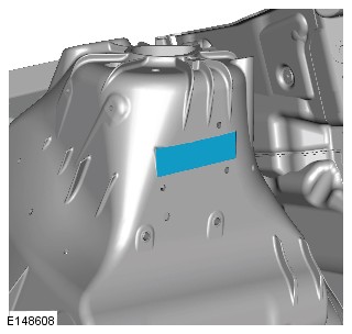
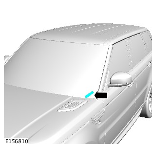
NAS/Canada located on the left B-pillar.
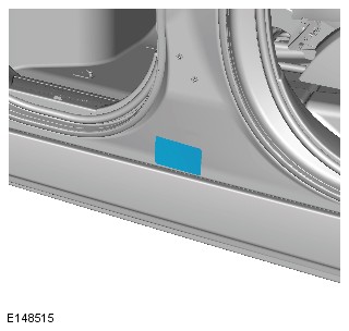
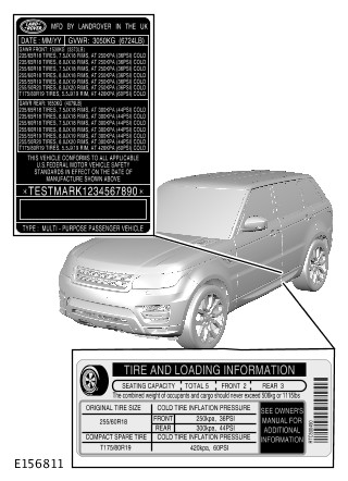
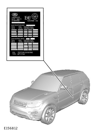
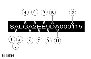
| VIN POSITION | CHARACTER | IDENTIFIES |
|---|---|---|
| 1 - 3 - World identifier | SAL | Jaguar Land Rover Ltd. (Land Rover) |
| 4 - Vehicle type | W | Range Rover Sport |
| 5 - Class | A | Standard |
| 6 - Body style | 2 | 5 Door station wagon: weight class E |
| 6 - Body style | 4 | 5 Door station wagon: weight class F |
| 7 - Transmission and steering | E | RHD Automatic: 8 speed |
| 8 - Engine | E | 508PS - AJ V8 5.0 SC Petrol |
| 8 - Engine | J | 448DT - V8 4.4 Diesel |
| 8 - Engine | K | 306DT - V6 3.0 Diesel |
| 8 - Engine | L | 306DT - V6 3.0 Diesel Hybrid |
| 8 - Engine | N | 204DT - 2.0 AJ200 Diesel |
| 8 - Engine | V | 306PS - V6 3.0 SC Petrol |
| 9 - Check digit | * | Derived by calculation |
| 10 - Model year | E | 2014 |
| 10 - Model year | F | 2015 |
| 10 - Model year | G | 2016 |
| 10 - Model year | H | 2017 |
| 11 - Plant | A | Solihull |
| 12 - Serial number | 0 - 9 | Unique six digit serial number |
# Active belts with driver and passenger frontal air bags and side inflatable restraint (1st and 2nd row) and driver knee air bag.
| VIN POSITION | CHARACTER | IDENTIFIES |
|---|---|---|
| 1 - 3 - World identifier | SAL | Jaguar Land Rover Ltd. (Land Rover) |
| 4 - Model range | W | Range Rover Sport |
| 5 - Class | J | S |
| 5 - Class | G | SE |
| 5 - Class | R | HSE |
| 5 - Class | V | Autobiography |
| 5 - Class | Z | SVR |
| 6 - Body style | 2 | 5 Door station wagon: weight class E |
| 6 - Body style | 4 | 5 Door station wagon: weight class F |
| 7- Transmission and steering | F | LHD Automatic: 8 speed |
| 8 - Engine | E | 508PS - AJ V8 5.0 SC Petrol |
| 8 - Engine | J | 448DT - V8 4.4 Diesel |
| 8 - Engine | K | 306DT - V6 3.0 Diesel |
| 8 - Engine | L | 306DT - V6 3.0 Diesel Hybrid |
| 8 - Engine | N | 204DT - 2.0 AJ200 Diesel |
| 8 - Engine | V | 306PS - V6 3.0 SC Petrol |
| 9 - Check digit | * | Derived by calculation |
| 10 - Model year | E | 2014 |
| 10 - Model year | F | 2015 |
| 10 - Model year | G | 2016 |
| 10 - Model year | H | 2017 |
| 11 - Plant | A | Solihull |
| 12 - Serial number | 0 - 9 | Unique six digit serial number |
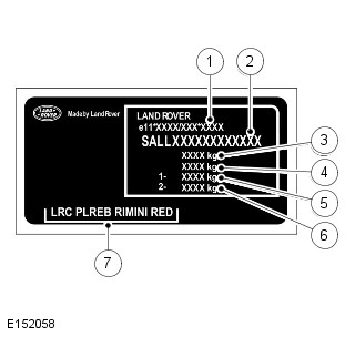
The VIN plate contains the following information:
- 1 - Type/Approval Number - If shown
- 2 - VIN Number
- 3 - Gross Vehicle Weight
- 4 - Gross Train Weight
- 5 - Front Axle Weight
- 6 - Rear Axle Weight
- 7 - Colour code/group
The Certification Label contains the following VIN information:
- VIN Number
- Bar code identification
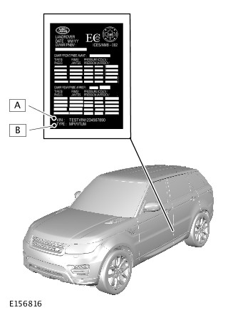
The Tire Pressure Certification Label contains the following VIN information:
- A - VIN Number
- B - Vehicle Type
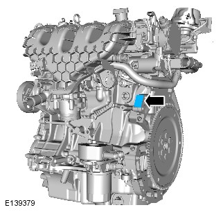
The 2.0L Petrol Engine Serial Number is stamped on the RH side of the cylinder block.
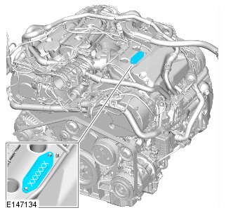
The 3.0L V6 Diesel Engine Serial Number is stamped on the left side of the cylinder head.
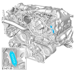
The 4.4L V8 Diesel Engine Serial Number is stamped on the left side of the cylinder head.
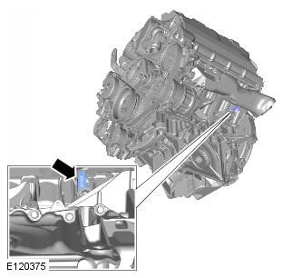
The 3.0L and 5.0L SC Petrol Engine Serial Number is stamped on the left side of the cylinder block.
The transmission serial number is on a plate attached to the left side of the transmission casing.
The Front Differential Serial Number is stamped on top of the differential casing and is located above the removable cross member.
The Rear Differential Serial Number is stamped on the underside of the differential casing adjacent to the front mounting.
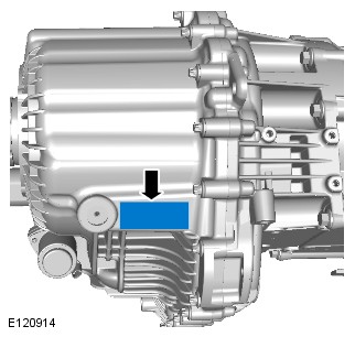
The Transfer Case serial number is stamped on the right side of the transfer case and may also be on a bar coded self-adhesive label attached to the case.