Range Rover Sport / L494 2017 STARTING SYSTEM
STARTING SYSTEM - TDV6 3.0L DIESEL /TDV6 3.0L DIESEL - GEN 1.5/TDV6 3.0L DIESEL - GEN 2 (G1509495)
| DESCRIPTION | NM | LB-FT | LB-IN |
|---|---|---|---|
| Starter motor to oil pan bolts | 47 | 35 | - |
| Battery positive terminal integral connector retaining nut | 10 | 7 | - |
| Solenoid terminal integral connector nut | 7 | - | 62 |
Description and Operation
STARTING SYSTEM - TDV6 3.0L DIESEL /TDV6 3.0L DIESEL - GEN 1.5/TDV6 3.0L DIESEL - GEN 2 (G1950031)
COMPONENT LOCATION - 1 OF 2

| ITEM | DESCRIPTION |
|---|---|
| 1 | Ignition switch |
| 2 | Brake pedal switch |
| 3 | Terrain Response (TR) switchpack |
| 4 | Body Control Module/Gateway Module (BCM/GWM) assembly |
COMPONENT LOCATION - 2 OF 2

| ITEM | DESCRIPTION |
|---|---|
| 1 | Brake vacuum sensor |
| 2 | Powertrain Control Module (PCM) |
| 3 | Starter motor |
| 4 | Pinion gear |
| 5 | Breather tube |
| 6 | Solenoid |
The starting system consists of an electric starter motor that engages with the ring gear on the crankshaft drive plate. Operation of the starter motor is controlled by the Powertrain Control Module (PCM).
In some markets the starting system incorporates an Auto stop/start system. The system is controlled by the PCM using Controller Area Network (CAN) messages and signals from other system components and modules to determine the correct conditions for system operation. The Auto stop/start system automatically stops and re-starts the engine when appropriate conditions are met. This reduces the amount of time the engine is running at idle speed which improves economy and reduces engine emissions.
The Auto stop/start system is automatically enabled each time the ignition is switched On. The driver can disable the system using the Auto stop/start switch.
The Auto stop/start system stops the engine when it is not needed. The engine will restart automatically when vehicle parameters are met and the driver releases the brake pedal.
To accommodate the increased motor starts, vehicles with the Auto stop/start system are equipped with an enhanced starter motor. For additional information, refer to:Battery and Cables (414-01 Battery, Mounting and Cables, Description and Operation).
STARTER MOTOR
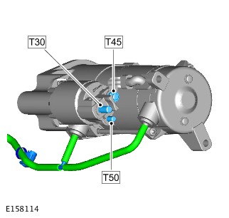
The starter motor is located on the rear right side of the oil pan. The rear of the starter motor is attached to a support bracket on the oil pan. The starter motor incorporates a snorkel breather pipe to assist with ventilation and sealing, during water submergence.
The starter motor is rated at 2 kW and comprises a series wound motor, an overrunning clutch and pinion, and a solenoid.
Power to operate the motor is supplied from Battery Junction Box (BJB). Power to operate the solenoid is supplied from the starter relay in the Engine Junction Box (EJB).
IGNITION SWITCH
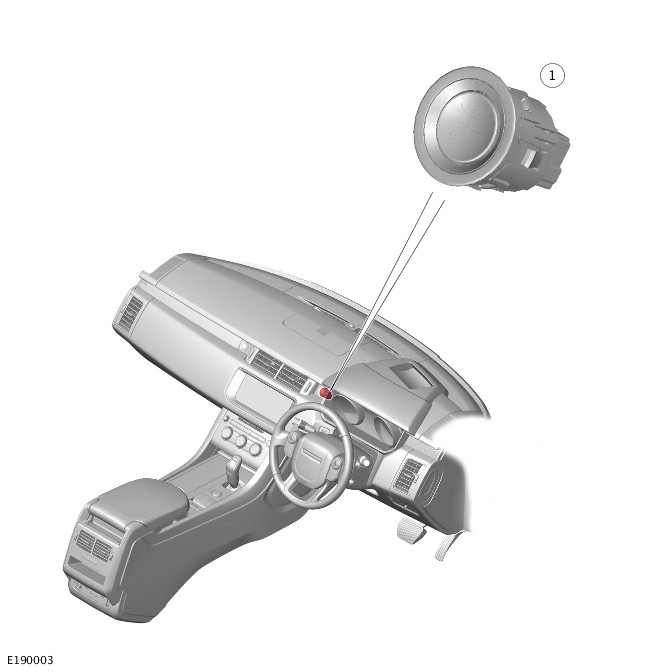
| ITEM | DESCRIPTION |
|---|---|
| 1 | Ignition switch |
The ignition switch is installed in the instrument panel and is hardwired to the Body Control Module/Gateway Module (BCM/GWM) assembly. When the switch is pressed two signal lines from the BCM/GWM assembly are connected to ground.
AUTO STOP/START SWITCH - IF EQUIPPED
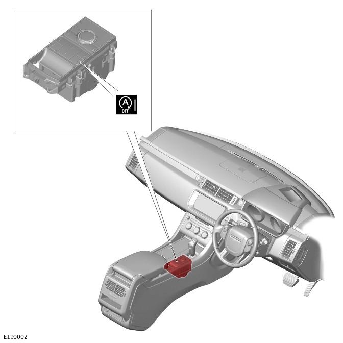
On vehicles with Auto stop/start system, the Auto stop/start switch is integrated into the Terrain Response (TR) switchpack in the floor console. An amber Light Emitting Diode (LED) in the Auto stop/start switch remains illuminated while the Auto stop/start system is active. Selection of the Auto stop/start switch is transmitted from the TR switchpack to the PCM on the High Speed (HS) Controller Area Network (CAN) chassis systems bus.
AUTO STOP/START WARNING INDICATOR - IF EQUIPPED
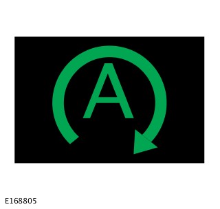
On vehicles with Auto stop/start system, an Auto stop/start warning indicator is located in the Instrument Cluster (IC). The warning indicator illuminates green when the engine stops during an Auto stop/start cycle, then goes off when the engine restarts. The warning indicator illuminates white when the Auto stop/start system is disabled. The warning indicator is controlled by a HS CAN powertrain systems bus message from the PCM.
BRAKE VACUUM SENSOR
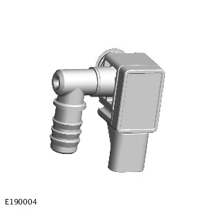
To ensure the brake system is never compromised, a brake vacuum sensor is installed to monitor vacuum reserves in the brake booster.
The brake vacuum sensor is mounted to the brake booster and hardwired to the Anti-lock Brake System (ABS) control module.
If the brake vacuum decreases below a set threshold while auto stop/start is enabled, the PCM either:
- Restarts the engine to replenish the vacuum reserves.
- Inhibits the engine shutting down if vacuum reserves are not sufficient.
An example of vacuum reserves depleting, is by the driver repeatedly pressing the brake pedal while the engine is shutdown during an auto stop/start stop. This action will initiate an engine restart when vacuum reserves decrease below the set threshold.
If a fault develops with the brake vacuum sensor a Diagnostic Trouble Code (DTC) will be logged in the PCM.
VEHICLES WITHOUT AUTO STOP/START SYSTEM
If the Remote Function Actuator (RFA) detects a valid smart key the driver will be able to start the engine. When the ignition switch is operated the Body Control Module/Gateway Module (BCM/GWM) assembly transmits a hardwired crank request. The crank request transmitted to the Powertrain Control Module (PCM). For additional information, refer to:Anti-Theft - Active (419-01A Anti-Theft - Active, Description and Operation).
The energized starter relay supplies battery power to the starter solenoid, which energizes and causes the pinion gear to engage with the ring gear.
When the starter solenoid is energized it also closes high-current contacts, which connects battery power from the Battery Junction Box (BJB) to the motor to turn the engine.
VEHICLES WITH AUTO STOP/START SYSTEM
At the beginning of a drive cycle, when the ignition switch is operated, the auto stop/start system operates in the same way as on vehicles without auto stop/start system.
The auto stop/start system is controlled by the PCM and the BCM/GWM assembly via FlexRay bus and signals from other system components and modules to determine the correct conditions for system operation. The auto stop/start system detects when it is appropriate to stop and start the engine.
The auto stop/start system automatically stops the engine in appropriate conditions, resulting in zero tailpipe emissions and saving fuel when the vehicle is stationary. When the driver is ready to move off, the engine instantly restarts. Sophisticated controls ensure that the auto stop/start system does not compromise the needs of either the driver or the vehicle.
The auto stop/start system can be enabled/disabled using the auto stop/start switch in the Terrain Response (TR) switchpack.
Software within the PCM controls the operation of the auto stop/start system. In addition to its own dedicated components the auto stop/start system encompasses many other vehicle systems.
Complex technology interconnects these systems and ensures all the necessary conditions are satisfied by monitoring, among others:
- Brake hydraulic system pressure.
- Transmission Control Switch (TCS) position.
- Road speed.
- The state of vital vehicle systems.
- Environmental conditions.
The driver will be notified that the engine stops by the auto stop/start warning indicator being illuminated in the Instrument Cluster (IC). Other warnings normally associated with an engine stoppage. For example the ignition and low oil pressure indicators, are suppressed so will not illuminate during an engine stoppage in an auto stop/start cycle.
The following conditions will prevent an auto stop:
- A steering wheel paddle switch has been used to select a gear (transmission Commandshift mode).
- The ambient air temperature is outside the range of 2 °C to 40 °C (36 °F to 104 °F).
- The ambient air pressure is below 720 hPa.
- The engine coolant temperature is outside the range of 20 °C to 107 °C (68 °F to 224 °F).
- Brake vacuum is less than the threshold value.
- The hood is open.
- The driver door is open.
- The driver seatbelt is not fastened.
- High demand from the climate control system requires the engine to be running, for example windshield demist selected.
- The battery charge is low.
- A Terrain Response (TR) special program is active.
- The Hill Descent Control (HDC) is active.
- The level in the fuel tank is too low (approximately 6 liters remaining in tank).
- Active regeneration of the Diesel Particulate Filter (DPF) is required or in progress.
- Auto stop/start system is disabled using the Auto stop/start switch.
While the vehicle is stationary, if a condition that prevented an auto stop is removed the PCM automatically performs an auto stop.
The PCM automatically restarts the engine when one of the following occurs:
- The brake pedal is released with Drive (D) or Sport (S) selected on the TCS.
- The accelerator pedal is pressed.
- A paddle switch is used to select a gear.
- Reverse (R) is selected on the TCS.
- Climate control system demand increases.
- The vehicle speed exceeds approximately 1 km/h (0.5 mph).
- Battery state of charge is near its lower threshold.
- Brake vacuum reduces below the threshold value.
- The Auto stop/start system is disabled using the Auto stop/start switch.
When the brake pedal is released during an auto restart the Anti-lock Brake System (ABS) control module briefly applies the brakes to hold the vehicle stationary until the engine has restarted.
The following will prevent an auto restart, and require use of the engine stop/start switch to restart the engine:
- The hood is open.
- The driver seatbelt is not fastened.
AUTO STOP/START STRATEGY
When the engine speed is less than 330 RPM, and an auto stop is initiated, the restarting of the engine is controlled via the starter motor. The starter motor has the capability of engaging with the transmission ring gear whilst still rotating. When the starter motor rotates the engine speed up to 330 RPM, the PCM then activates the fueling and engine systems to restart the engine.
When the engine speed is above 330 RPM, and an Auto stop is initiated, the restarting of the engine is controlled by the PCM. The PCM activates the fueling and engine systems only.
CONTROL DIAGRAM - 1 OF 2 - STARTING SYSTEM WITHOUT AUTO STOP/START SYSTEM
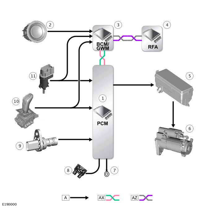
A = HARDWIRED; AX = FLEXRAY BUS; AZ = HIGH SPEED (HS) CONTROLLER AREA NETWORK (CAN) BODY SYSTEMS BUS.
| ITEM | DESCRIPTION |
|---|---|
| 1 | Powertrain Control Module (PCM) |
| 2 | Ignition switch |
| 3 | Body Control Module/Gateway Module (BCM/GWM) assembly |
| 4 | Remote Function Actuator (RFA) |
| 5 | Engine Junction Box (EJB) |
| 6 | Starter motor |
| 7 | Ground |
| 8 | Power supply |
| 9 | Crankshaft Position (CKP) sensor |
| 10 | Transmission Control Switch (TCS) - park/neutral signal |
| 11 | Brake pedal switch |
CONTROL DIAGRAM - 2 OF 2 - STARTING SYSTEM WITH AUTO STOP/START SYSTEM

A = HARDWIRED; AM = HIGH SPEED (HS) CONTROLLER AREA NETWORK (CAN) CHASSIS SYSTEMS BUS; AN = HS CAN POWERTRAIN SYSTEMS BUS; AV = HS CAN COMFORT SYSTEMS BUS; AX = FLEXRAY BUS; AZ = HS CAN BODY SYSTEMS BUS.
| ITEM | DESCRIPTION |
|---|---|
| 1 | Powertrain Control Module (PCM) |
| 2 | Remote Function Actuator (RFA) |
| 3 | Terrain Response (TR) switchpack |
| 4 | Body Control Module/Gateway Module (BCM/GWM) assembly |
| 5 | Anti-lock Brake System (ABS) control module |
| 6 | Transmission Control Switch (TCS) |
| 7 | Instrument Cluster (IC) |
| 8 | Engine Junction Box (EJB) |
| 9 | Starter motor |
| 10 | Ground |
| 11 | Power supply |
| 12 | Accelerator Pedal Position (APP) sensor |
| 13 | Ambient Air Temperature (AAT) sensor |
| 14 | Crankshaft Position (CKP) sensor |
| 15 | Engine Coolant Temperature (ECT) sensor |
| 16 | Brake pedal switch |
| 17 | Transmission Control Switch (TCS) - park/neutral signal |
| 18 | Brake vacuum sensor |
| 19 | Ignition switch |
Diagnosis and Testing
STARTING SYSTEM - TDV6 3.0L DIESEL /TDV6 3.0L DIESEL - GEN 1.5/TDV6 3.0L DIESEL - GEN 2 (G1882793)
For a detailed description of the starting system and operation, refer to the relevant Description and Operation section of the workshop manual. REFER to:Starting System (303-06A Starting System - TDV6 3.0L Diesel /TDV6 3.0L Diesel - Gen 1.5/TDV6 3.0L Diesel - Gen 2, Description and Operation).
Diagnosis by substitution from a donor vehicle is NOT acceptable. Substitution of control modules does not guarantee confirmation of a fault and may also cause additional faults in the vehicle being checked and/or the donor vehicle.
Check and rectify basic faults before beginning diagnostic routines involving pinpoint tests.
- Verify the customer concern.
- Visually inspect for obvious signs of mechanical and electrical damage.
Visual Inspection
| MECHANICAL | ELECTRICAL |
|---|---|
|
|
- If an obvious cause for an observed or reported concern is found, correct the cause (if possible) before proceeding to the next step.
- If the cause is not visually evident, verify the symptom and refer to the Symptom Chart, alternatively check for Diagnostic Trouble Codes (DTCs) and refer to the DTC Index.
- Check DDW for open campaigns. Refer to the corresponding bulletins and SSM's which may be valid for the specific customer complaint and carry out the recommendations as needed.
| SYMPTOM | POSSIBLE CAUSES | ACTION |
|---|---|---|
| The engine does not crank (starter motor does not turn) |
|
Make sure the gear selector is in the P or N position and correctly adjusted. Check the battery condition and state of charge. Check for DTCs indicating an immobilizer fault. Check the starter motor relay, ignition switch and generator circuits. Refer to the electrical guides. Check for TCM and ECM DTCs. Check that the engine turns freely |
| The engine does not crank (starter motor does turn) |
|
Check the starter motor installation (fasteners tight, starter motor square to engine, etc). Check the flywheel/drive plate ring gear teeth for damage, foreign objects, etc |
| Engine cranks too slowly |
|
Check the battery condition and state of charge. Check the starter motor circuits. Refer to the electrical guides. Check the engine oil grade and condition |
| Engine cranks too fast |
|
Check the engine compressions |
| Excessive starter motor noise |
|
Check the starter motor installation (fasteners tight, motor square to engine, etc). Check the starter motor casing condition. Check the flywheel/drive plate ring gear teeth for damage, foreign objects, etc |
| ECO (stop/start) system inoperative |
|
NOTE:
"ECO STOP/START FAULT" will be displayed in the instrument cluster message centre when the system is inoperative due to a fault.
|
The inhibit conditions listed below will not set Diagnostic Trouble Codes (DTCs) but will set flags which can be viewed using the manufacturer approved diagnostic system - Datalogger / Powertrain Control Module (PCM). Normal ECO system operation will resume when an inhibit condition is no longer present, but the battery related inhibits may persist for some time.
Do not reset the Battery Monitoring System (BMS) to rectify battery condition inhibits. This may temporarily restore ECO system operation but will lead to a recurrence of the fault.
| INHIBITS |
|---|
|
For a list of Diagnostic Trouble Codes (DTCs) that could be logged on this vehicle, please refer to Section 100-00. REFER to:Diagnostic Trouble Code Index - TDV6 3.0L Diesel /TDV6 3.0L Diesel - Gen 1.5/TDV6 3.0L Diesel - Gen 2, DTC: Powertrain Control Module B10A2-07 to P02D7-32 (100-00 General Information, Description and Operation).

For a list of Diagnostic Trouble Codes (DTCs) that could be logged on this vehicle, please refer to Section 100-00. REFER to:Diagnostic Trouble Code Index - TDV6 3.0L Diesel /TDV6 3.0L Diesel - Gen 1.5/TDV6 3.0L Diesel - Gen 2, DTC: Powertrain Control Module B10A2-07 to P02D7-32 (100-00 General Information, Description and Operation).
STARTING SYSTEM - TDV6 3.0L DIESEL /TDV6 3.0L DIESEL - GEN 1.5/TDV6 3.0L DIESEL - GEN 2
AUTO STOP/START SYSTEM (G2309687)
For a detailed description of the auto stop/start system, refer to the relevant Description and Operation section of the workshop manual.REFER to:Starting System (303-06A Starting System - TDV6 3.0L Diesel /TDV6 3.0L Diesel - Gen 1.5/TDV6 3.0L Diesel - Gen 2, Description and Operation).
Diagnosis by substitution from a donor vehicle is NOT acceptable. Substitution of control modules does not guarantee confirmation of a fault, and may also cause additional faults in the vehicle being tested and/or the donor vehicle.
-
If a control module or a component is suspect and the vehicle remains under manufacturer warranty, refer to the Warranty Policy and Procedures manual, or determine if any prior approval programme is in operation, prior to the installation of a new module/component.
-
When performing voltage or resistance tests, always use a digital multimeter that has the resolution ability to view 3 decimal places. For example, on the 2 volts range can measure 1mV or 2 K Ohm range can measure 1 Ohm. When testing resistance always take the resistance of the digital multimeter leads into account.
-
Check and rectify basic faults before beginning diagnostic routines involving pinpoint tests.
- Verify the customer concern
- Visually inspect for obvious signs of damage and system integrity
| MECHANICAL | ELECTRICAL |
|---|---|
|
|
- If an obvious cause for an observed or reported concern is found, correct the cause (if possible) before proceeding to the next step
- If the cause is not visually evident, verify the symptom and refer to the Symptom Chart, alternatively check for Diagnostic Trouble Codes (DTCs) and refer to the DTC Index
- Check JLR claims submission system for open campaigns. Refer to the corresponding bulletins and SSMs which may be valid for the specific customer complaint and carry out the recommendations as required.
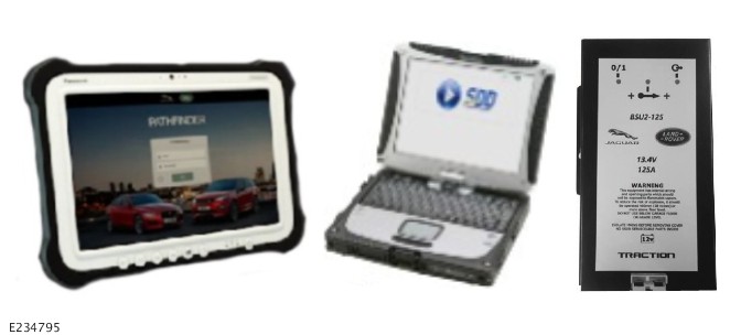
One of the first instructions when using the stop start health check is to disconnect the battery support unit or battery charger – If either is connected when the engine is started an inhibit will be present for that ignition cycle
| SYMPTOM | POSSIBLE CAUSE | ACTION |
|---|---|---|
| Auto Stop/Start inhibited by fuel adaption process after customer visit to the retailer |
|
|
-
Performing any of the actions listed above can cause the fuel adaptations to be cleared, this will cause a short term inhibit condition for the Auto Stop/Start system and is a known and expected vehicle reaction. Normal Auto Stop/Start functionality will return when the fuel adaptation has completed
-
Should a customer express this concern, while there are a number of inhibit conditions possible the fuel adaptation is the most likely following a very recent repair by a retailer. The stop start health check is the only application used by Jaguar Land Rover to confirm which if any inhibit condition is present when a vehicle is presented to a retailer
-
This application is a health check which displays any Stop/Start system inhibits present. It will not diagnose anything as the various system inhibits are a normal function of the Stop/Start system. To resolve and clear all other Stop/Start inhibits that are present - follow the Service Instruction below
SDD only

- Connect the Jaguar Land Rover approved diagnostic equipment to the vehicle and begin a new diagnostic session, by reading the VIN for the current vehicle and initiating the data collect sequence
- Follow the Jaguar Land Rover approved diagnostic equipment prompts
- If the hyperlink is not available, the application can be found as follows:
- • Select the Diagnosis Session Type
- • Select any of the following symptoms
- • Powertrain - Engine System - Starting System - Start-stop system
- • From 'Recommendations', run: Powertrain control module - Stop/Start system - Health check
- Before commencing any Stop/Start investigations the following conditions must be met:
- • There must be no malfunction indicators present
- When running the application for the first time on a vehicle the technician will experience a delay before the “Start Engine” instruction is given. This delay is normal and caused by the application checking that the associated parameters are available on the vehicle under test
- The Stop/Start Health Check screen is divided into 3 areas
- The first part of the screen (the left hand side) is the application pre-conditions - the screen displays the basic parameters that are controlled by upper and lower limits e.g. temperatures, battery condition, road speed etc. These parameters are subject to the vehicle capabilities and will be seen to vary from one model to another. The way the application functions will see some of the parameters changing colour during the course of the test process, unless there is an inhibit displayed in the centre section which supports the parameter these colour changes should be ignored
- The centre section has three categories
- Driver influence - These inhibit conditions cover the Hood, Drivers Door, Drivers seat belt, Air conditioning and the Automatic Stop/Start switch
- Vehicle influence - This covers some of the inhibit conditions that are related to the vehicle function
- Additional inhibits - These conditions are too numerous to display as a list in the same way as the previous categories. To prevent confusion this area will only display active inhibits, for this reason on first start of the engine it is normal to see a number of inhibit conditions displayed for a period of time after the start, gearbox, engine, battery and ambient temperature are all potential inhibits with various 'time-related warm up periods. Various short term adaptation inhibits may also be displayed at this time
- The right hand side of the screen is the area of the screen used to display help text for active inhibits when the mouse hover-over feature is used. Any instructions or related active text will be displayed in this area, information related to the stop start drive cycle is also displayed here
- The technician can exit the test at any time by selecting the 'Exit' button, printout of the test results will be offered on exit from the application and on completion of a successful Auto Stop/Start test
- Application selection screen
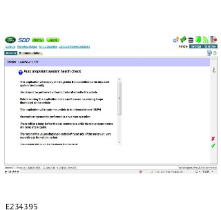
- Screen after engine start
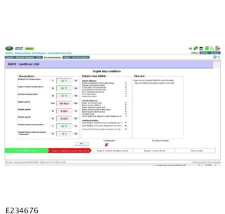
- With Help text when short term conditions cleared – Ready to execute drive cycle

- Drive cycle complete
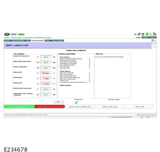
This screen indicates that the inhibit condition has cleared, as the application is now out of sync with the vehicle the only correct action is to Stop the vehicle and ignore its actions and restart the application.
Starting a fresh health check will confirm that the vehicle now functions correctly, a copy of the PDF file can be presented as proof of function.
- Customer explanation
- This condition may be caused by performing a DTC clear
- This will require the vehicle to be driven between 30MPH and 50MPH for 2 minutes followed by and engine idle for up to 1 minute
- The application should be used during the drive cycle to confirm this inhibit has cleared
- If the inhibit condition does not clear a full drive cycle may be required
- The time frame required to clear the adaptations can and does vary subject to engine variant, it cannot be confirmed that all our vehicles are sold with this inhibit condition present nor should it be implied
- The customer needs to be informed that the inhibit will clear once the adaptation process is complete, this is the normal operating condition for a vehicle being returned to a customer following any repair process that involves software updates or where a concern has been resolved which required a DTC clear to be performed to confirm the issue has been fixed
- One of the features associated with SDD is the ability to produce a PDF file to printout and hand to the customer to confirm the condition of the vehicle
- When all tasks are complete, exit the current session by selecting the Session tab and then selecting the Close Session option
- Disconnect the Jaguar Land Rover approved diagnostic equipment
Starting the application - for Pathfinder vehicles
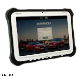
This procedure requires version 188 or later
- Before commencing any Stop/Start investigations the following conditions must be met:
- There must be no malfunction indicators present
DO NOT clear any DTCs as this will induce a Stop/Start inhibit condition requiring a short drive cycle to be undertaken, the application can be used to confirm that the adaptations have cleared. Only when these conditions have been met should any Stop/Start investigations be undertaken
- Connect the Jaguar Land Rover approved diagnostic equipment to the vehicle and begin a new diagnostic session
- Select - Service
Ensure the Jaguar Land Rover battery support unit is removed before engine start as this will cause an inhibit

- Select - Stop Start System Health Check
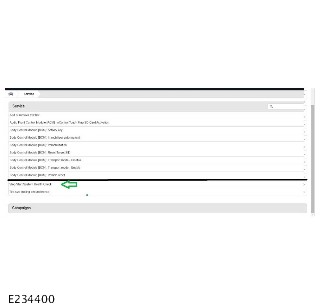
- Application opening screen
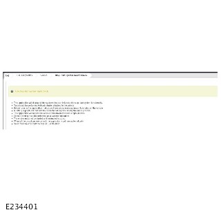
- Application run up, wait for application to open
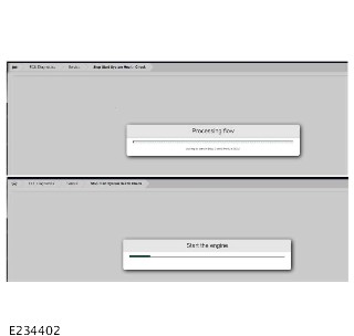
- Application with inhibit present including help text
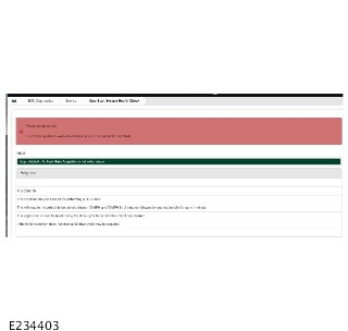
- Customer explanation SDD and Pathfinder
- This condition may be caused by performing a DTC clear
- This will require the vehicle to be driven between 30MPH and 50MPH for 2 minutes followed by and engine idle for up to 1 minute
- The application should be used during the drive cycle to confirm this inhibit has cleared
- If the inhibit condition does not clear a full drive cycle may be required
- The time frame required to clear the adaptations can and does vary subject to engine variant, it cannot be confirmed that all our vehicles are sold with this inhibit condition present nor should it be implied
- The customer needs to be informed that the inhibit will clear once the adaptation process is complete, this is the normal operating condition for a vehicle being returned to a customer following any repair process that involves software updates or where a concern has been resolved which required a DTC clear to be performed to confirm the issue has been fixed
- When all tasks are complete, exit the current session by selecting the Session tab and then selecting the Close Session option
- Disconnect the Jaguar Land Rover approved diagnostic equipment
Removal and Installation
STARTING SYSTEM - TDV6 3.0L DIESEL /TDV6 3.0L DIESEL - GEN 1.5/TDV6 3.0L DIESEL - GEN 2
STARTER MOTOR (G1509496)
- 86.60.01
- STARTER MOTOR - RENEW
- 3000 CC, TDV6
- 0.90
- USED WITHINS
-
Removal steps in this procedure may contain installation details.
-
Some variation in the illustrations may occur, but the essential information is always correct.
- Disconnect the battery ground cable.
Refer to:Specifications (414-00 Battery and Charging System - General Information, Specifications).
-
Raise and support the vehicle.WARNING:
Make sure to support the vehicle with axle stands.
-
Refer to:Engine Undershield (501-02 Front End Body Panels, Removal and Installation).
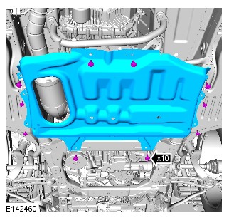


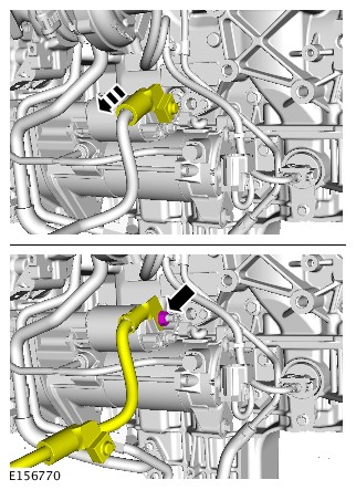
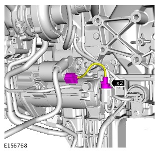
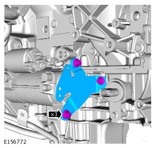


- To install, reverse the removal procedure.